WO2014119328A1 - 電池状態推定装置 - Google Patents
電池状態推定装置 Download PDFInfo
- Publication number
- WO2014119328A1 WO2014119328A1 PCT/JP2014/000511 JP2014000511W WO2014119328A1 WO 2014119328 A1 WO2014119328 A1 WO 2014119328A1 JP 2014000511 W JP2014000511 W JP 2014000511W WO 2014119328 A1 WO2014119328 A1 WO 2014119328A1
- Authority
- WO
- WIPO (PCT)
- Prior art keywords
- battery state
- battery
- value
- function
- model
- Prior art date
- Legal status (The legal status is an assumption and is not a legal conclusion. Google has not performed a legal analysis and makes no representation as to the accuracy of the status listed.)
- Ceased
Links
Images


Classifications
-
- G—PHYSICS
- G01—MEASURING; TESTING
- G01R—MEASURING ELECTRIC VARIABLES; MEASURING MAGNETIC VARIABLES
- G01R31/00—Arrangements for testing electric properties; Arrangements for locating electric faults; Arrangements for electrical testing characterised by what is being tested not provided for elsewhere
- G01R31/36—Arrangements for testing, measuring or monitoring the electrical condition of accumulators or electric batteries, e.g. capacity or state of charge [SoC]
- G01R31/367—Software therefor, e.g. for battery testing using modelling or look-up tables
-
- G—PHYSICS
- G01—MEASURING; TESTING
- G01R—MEASURING ELECTRIC VARIABLES; MEASURING MAGNETIC VARIABLES
- G01R31/00—Arrangements for testing electric properties; Arrangements for locating electric faults; Arrangements for electrical testing characterised by what is being tested not provided for elsewhere
- G01R31/36—Arrangements for testing, measuring or monitoring the electrical condition of accumulators or electric batteries, e.g. capacity or state of charge [SoC]
- G01R31/382—Arrangements for monitoring battery or accumulator variables, e.g. SoC
-
- H—ELECTRICITY
- H01—ELECTRIC ELEMENTS
- H01M—PROCESSES OR MEANS, e.g. BATTERIES, FOR THE DIRECT CONVERSION OF CHEMICAL ENERGY INTO ELECTRICAL ENERGY
- H01M10/00—Secondary cells; Manufacture thereof
- H01M10/42—Methods or arrangements for servicing or maintenance of secondary cells or secondary half-cells
- H01M10/48—Accumulators combined with arrangements for measuring, testing or indicating the condition of cells, e.g. the level or density of the electrolyte
-
- H—ELECTRICITY
- H01—ELECTRIC ELEMENTS
- H01M—PROCESSES OR MEANS, e.g. BATTERIES, FOR THE DIRECT CONVERSION OF CHEMICAL ENERGY INTO ELECTRICAL ENERGY
- H01M10/00—Secondary cells; Manufacture thereof
- H01M10/05—Accumulators with non-aqueous electrolyte
- H01M10/052—Li-accumulators
-
- Y—GENERAL TAGGING OF NEW TECHNOLOGICAL DEVELOPMENTS; GENERAL TAGGING OF CROSS-SECTIONAL TECHNOLOGIES SPANNING OVER SEVERAL SECTIONS OF THE IPC; TECHNICAL SUBJECTS COVERED BY FORMER USPC CROSS-REFERENCE ART COLLECTIONS [XRACs] AND DIGESTS
- Y02—TECHNOLOGIES OR APPLICATIONS FOR MITIGATION OR ADAPTATION AGAINST CLIMATE CHANGE
- Y02E—REDUCTION OF GREENHOUSE GAS [GHG] EMISSIONS, RELATED TO ENERGY GENERATION, TRANSMISSION OR DISTRIBUTION
- Y02E60/00—Enabling technologies; Technologies with a potential or indirect contribution to GHG emissions mitigation
- Y02E60/10—Energy storage using batteries
Definitions
- the present invention relates to a battery state estimation device that estimates a stable value of a battery state that changes with time.
- a battery Since a battery has a capacity component in an equivalent circuit, it takes time to stabilize the voltage between its terminals when charging and discharging.
- Patent Document 1 describes that the estimation of the open circuit voltage of a battery uses a linear approximation with data of 20 to 30 minutes from the end of charging and discharging. Further, Patent Document 2 describes that a coefficient of an exponential decay function of the fourth order or higher is determined and used as an approximate expression of the open circuit voltage of the secondary battery. Patent Document 3 describes that an inverse function is used for estimating a stable open circuit voltage of a battery.
- the battery state estimation apparatus includes an actual value acquisition unit that acquires actual values for a measurement period in which a battery state that changes with time is predetermined for a charged / discharged battery, and a plurality of battery state models Based on the results of the model function determination unit that determines the function form of the model function based on the actual measurement value, the multiple prediction unit that predicts the change in the battery state for each of the multiple model functions for which the function form is determined, and the multiple prediction unit And an estimation unit for calculating an estimated stable value of the battery state.
- a battery state that changes with time can be accurately predicted for a charged / discharged battery.
- FIG. 1 is a configuration diagram of a battery charge / discharge control system including a battery state estimation device in an example of an embodiment according to the present invention. It is a figure which shows an example of the some model function used with the battery state estimation apparatus in an example of embodiment which concerns on this invention. It is a figure which shows the other example of the some model function used with the battery state estimation apparatus in an example of embodiment which concerns on this invention. It is a flowchart which shows the procedure of the battery state estimation performed with the battery state estimation apparatus in an example of embodiment which concerns on this invention. It is a figure which shows the weight used with the battery state estimation apparatus in an example of embodiment which concerns on this invention.
- FIG. 1 is a configuration diagram of a battery charge / discharge control system 1.
- the battery charge / discharge control system 1 includes a battery charge / discharge unit 2.
- the battery charging / discharging unit 2 includes a battery 3, a current detection unit 6 that detects a current that is input to and output from the battery 3 when the battery 3 is connected to the discharge load 4 or the charging power source 5, and a terminal voltage of the battery 3.
- a voltage detection unit 7 for detection is included.
- the battery charge / discharge control system 1 further includes a charge / discharge control device 8, a battery state estimation device 10, and a storage unit 11 connected to the battery state estimation device 10.
- FIG. 1 shows the discharge load 4 and the charging power source 5 connected to the battery charging / discharging unit 2.
- the battery 3 to be subjected to battery state estimation is a secondary battery in which the battery state changes with time, and is a chargeable / dischargeable battery here.
- a lithium ion battery can be the target of battery state estimation.
- a nickel metal hydride battery, an alkaline battery, a lead storage battery, or the like may be the target of battery state estimation.
- the discharge load 4 is a device that uses the discharge power supplied from the battery 3.
- examples include household electric lamps, electric devices such as personal computers, factory lighting fixtures, electric devices, and the like.
- it may be a rotating electric machine, an electric device or the like mounted on a vehicle.
- the charging power source 5 is a power generation device such as a commercial power source 12 or a solar cell 13, and these are connected to the battery 3 via a charger 14.
- the current detection unit 6 is a current detection unit that distinguishes and detects the charging current input from the charging power source 5 to the battery 3 and the discharging current output from the battery 3 to the discharge load 4.
- an appropriate ammeter can be used as the current detection unit 6, an appropriate ammeter can be used.
- the current value detected by the current detection unit 6 is transmitted to the charge / discharge control device 8 through an appropriate signal line, with the charge current value as a positive current value and the discharge current value as a negative current value, and the charge / discharge command value and the actual measurement value are measured. It is used for control of the battery charging / discharging unit 2 such as confirmation of deviation between values.
- the current value detected by the current detection unit 6 is a current characteristic value that is one of the battery states
- the battery state estimation device 10 performs estimation related to the current characteristic value
- the current detected by the current detection unit 6 The value is transmitted to the battery state estimation device 10 through an appropriate signal line as an actual measurement current value used as a basis for estimation, and is used for estimation processing such as calculating SOC (State Of Charge) indicating the state of charge of the battery. .
- SOC State Of Charge
- the voltage detection unit 7 is voltage detection means for detecting the voltage between the terminals of the battery 3. As the voltage detector 7, an appropriate voltmeter can be used. The voltage value detected by the voltage detector 7 is transmitted to the charge / discharge control device 8 through an appropriate signal line, and is used for monitoring the voltage state of the battery. In addition, since the voltage value detected by the voltage detection unit 7 is a voltage characteristic value that is one of the battery states, the voltage detected by the voltage detection unit 7 is used when the battery state estimation device 10 performs estimation regarding the voltage characteristic value. The value is transmitted as an actually measured voltage value used as a basis for estimation to the battery state estimation device 10 through an appropriate signal line.
- the charging / discharging control device 8 controls charging / discharging of the battery 3 by outputting a charging / discharging command according to the request of the discharging load 4 and the charging power source 5.
- the charge / discharge control device 8 can be configured by a suitable computer.
- the battery state estimation device 10 is a device that estimates the stable value of the battery state that changes with time using the detected value of the current detection unit 6 or the detection value of the voltage detection unit 7 that has been transmitted. Such a battery state estimation device 10 can be configured by an appropriate computer.
- the battery state that changes with time means that when the battery 3 is charged / discharged, the input / output current value and the inter-terminal voltage value change with time depending on the capacity component, inductance component, and resistance component of the battery 3. Is the state of the battery 3 according to Therefore, the battery state that changes with time includes SOC (State Of Charge) indicating the state of charge of the battery in addition to the current state and voltage state of the battery 3.
- SOC State Of Charge
- open circuit state Looking at the open circuit voltage, the voltage between the terminals decreases with time. Conversely, a discharge command is output from the charge / discharge control device 8 to the battery 3, a predetermined discharge is performed from the battery 3 to the discharge load 4, and the battery 3 is disconnected from the discharge load 4 when the discharge is completed. Open circuit state.
- the voltage between the terminals of the battery 3 in the open circuit state is an open circuit voltage (Open Circuit Voltage: OCV). Looking at the open circuit voltage, the open circuit voltage gradually decreases with time after the completion of charging, and the open circuit voltage gradually increases with time after the completion of discharging. Thus, open circuit voltage is one of the battery states that change over time.
- the open circuit voltage is described as a battery state that changes with time.
- the battery state estimation device 10 estimates a stable value of the open circuit voltage in a short time by calculation.
- the battery state estimation device 10 determines an actual measurement value acquisition unit 20 that acquires an actual measurement value for a predetermined measurement period for a battery state that changes with time, and a function form of a plurality of model functions that model the battery state based on the actual measurement value.
- a model function determination unit 21 that performs the calculation, a plurality of prediction units 22 that predict changes in the battery state for each of the plurality of model functions whose function forms have been determined, and an estimated stable value of the battery state based on the results of the plurality of prediction units
- the estimation part 23 to be configured is provided.
- Such a function can be realized by the battery state estimation device 10 executing software. Specifically, these functions can be realized by the battery state estimation device 10 executing a battery state estimation program. Some of these functions may be realized by hardware.
- the storage unit 11 connected to the battery state estimation device 10 is a memory that stores programs used in the battery state estimation device 10.
- a plurality of model functions for modeling the battery state are stored as the model function file 25.
- the estimation unit 23 of the battery state estimation device 10 selects two or more appropriate model functions from among a plurality of model functions stored in the model function file 25 of the storage unit 11, and a plurality of predicted values predicted by these model functions. Based on this, the stable value of the battery state is estimated.
- a plurality of model functions are used because the voltage behavior after charging / discharging of the battery 3 is complicatedly influenced by the type of battery 3, the environmental temperature, the amount of current during charging / discharging, the SOC value, etc., and the same model in these cases This is because functions are not always suitable. This is also because the battery state of the battery 3 cannot be modeled by one model function over the entire charge / discharge region. Even when one model function can be used, the same value is not always suitable as a parameter for determining the function form of the model function.
- the model function file 25 stores a plurality of model functions. One of them is a first model function 26 in which the battery state changes exponentially with respect to time. Further, a second model function 27 in which the battery state changes logarithmically with respect to time is stored. Other model functions include a linear model function in which the battery state changes linearly with respect to time, an inversely proportional model function in which the battery state is inversely proportional to time, a function using a linear sum of powers of elapsed time t, A sigmoid function or the like in which the battery state asymptotically approaches the convergence value with respect to time is stored.
- the first model function 26 and the second model function 27 are used as a plurality of model functions in the battery state estimation device 10 will be described.
- the storage unit 11 is described as being independent of the battery state estimation device 10, but these may be configured to be included in the battery state estimation device 10. Further, although the battery state estimation device 10 is described as an independent device different from the charge / discharge control device 8, the battery state estimation device 10 may be configured as a part of the charge / discharge control device 8.
- the first model function 26 and the second model function 27 stored in the model function file 25 will be described with reference to FIGS.
- the first model function 26 and the second model function 27 are functions indicating the relationship between the predicted value V EST of the open circuit voltage of the battery 3 and the elapsed time t from the completion of discharge.
- FIG. 2 is a diagram showing the first model function 26.
- the first model function 26 has a function form represented by equation (1) when an open circuit voltage at time t 0 is given as V 0 as an initial value.
- a and time constant ⁇ are parameters that determine a specific function form.
- the first model function 26 has a function form in which the open circuit voltage as the battery state changes exponentially with respect to time.
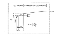
- FIG. 3 is a diagram showing the second model function 27.
- the second model function 27 as an initial value, the open circuit voltage when the time t 0 V 0, the open circuit voltage when the time t 1 V 1, the open circuit voltage when the time t 2 at V 2 When given, it has the function form shown in equation (2).
- R, T, and ⁇ V are parameters that determine a specific function form. R is given by equation (3).
- the second model function 27 has a function form in which the open circuit voltage in the battery state changes logarithmically in terms of time.
- ⁇ V is a unit in which the open circuit voltage rises with respect to time
- the elapsed time when the nth ⁇ occurs is TR It has a function form of (n-1) .
- the function form of the second model function 27 is determined using R, T, and ⁇ V as parameters.
- the first model function 26 Comparing the first model function 26 and the second model function 27, when the time constant ⁇ when the open circuit voltage decreases with time is large, the first model function 26 is used to estimate the stable value of the open circuit voltage. Even if applied, there is little error.
- applying the first model function 26 to the estimation of the stable value of the open circuit voltage greatly affects the measured initial value and the error of ⁇ . To do. In that case, it is less error to use the second model function 27 having a gradual function form to estimate the stable value of the open circuit voltage.
- the first model function 26 in FIG. 2 and the second model function 27 in FIG. 3 are stored in the model function file 25 of the storage unit 11. 2 and 3 show the case of discharging, but even in the case of charging, the function forms of the first model function 26 and the second model function 27 are the same, and only the parameters, symbols, and the like are changed. It is.
- the format of the first model function 26 and the second model function 27 stored in the model function file 25 has been described as a map.
- the format of the model function file 25 may be a format other than the map as long as the value indicating the battery state and the time are associated with each other.
- a format such as a ROM that outputs a value indicating a battery state when a lookup table, a mathematical expression, and a time t are input may be used.
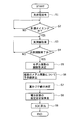
- FIG. 4 is a flowchart showing a procedure for estimating the battery state.
- the procedure in FIG. 4 corresponds to each processing procedure of the battery state estimation program.
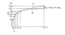
- FIG. 5 is a diagram showing how the estimated stable value is calculated in FIG.
- the battery state is estimated when a charge / discharge command is output from the charge / discharge control device 8 (S1).
- a discharge command is output from the charge / discharge control device 8.
- the battery 3 executes the discharge of the content of the discharge command to the discharge load 4.
- the battery state estimation device 10 does nothing.
- the battery state estimation device 10 determines whether or not the measurement timing has been reached (S2).
- the measurement timing is a timing at which an actual measured value of the voltage between the terminals of the battery 3 that is the premise can be measured in order to estimate the stable value of the open circuit voltage after the battery 3 is completely discharged. In this case, when the battery 3 is in an open circuit state, the determination in S2 is affirmed.
- the determination of S2 can be affirmed.
- the discharge completion time is included in the discharge command output from the charge / discharge control device 8
- the determination of S2 can be affirmed when the discharge completion time has elapsed.
- S3 an actual measurement value of the open circuit voltage of the battery 3 is acquired (S3).
- This processing procedure is executed by the function of the actual measurement value acquisition unit 20 of the battery state estimation device 10.
- the detection value transmitted from the voltage detection unit 7 is acquired.
- a plurality of actual measurement values are acquired at different times depending on sampling.
- the measurement period is set so that the measured value data acquired in S3 is sufficient to determine the function-type parameters of the first model function 26 and the function-type parameters of the second model function 27.
- a measurement period is set including not only the number of data but also that the acquired actual measurement value is an appropriate voltage interval. If the measurement period is too long, it will be close to the stable value of the open circuit voltage, and the value of the estimation will be reduced, so the measurement period should be the minimum necessary in consideration of the required accuracy of estimation of the stable value of the open circuit voltage. Is preferred.
- the function parameters of the first model function 26 and the function parameters of the second model function 27 are then determined (S5).
- This processing procedure is executed by the function of the model function determination unit 21 of the battery state estimation device 10.
- calculation is performed to determine A and ⁇
- R, T, and ⁇ V are determined.
- a known technique such as a least square method can be used to determine a plurality of parameters of a function using a plurality of actually measured values.
- the value of the open circuit voltage at the predetermined prediction time t S is changed to the first model function 26 and the second model.
- each is calculated as a predicted value (S6).
- This processing procedure is executed by the function of the multiple prediction unit 22 of the battery state estimation device 10.
- the predicted time t S is set to a time when the open circuit voltage of the battery 3 is considered to be a sufficiently stable value.
- the predicted time t S can be obtained experimentally in advance for the battery 3. As an example, the measurement period can be 10 minutes and the predicted time t S can be one hour later.
- FIG. 5 is a diagram illustrating calculation of the predicted value V S1 by the first model function 26 and the predicted value V S2 by the second model function 27 at time t 0 .
- the horizontal axis represents time
- the vertical axis represents the open circuit voltage V.
- the measurement period is from time t 0 to time t 4 , and in this case, five actually measured values V 0 to V 4 are acquired.
- FIG. 5 shows a function form 30 of the first model function 26 and a function form 31 of the second model function 27 determined based on the five actually measured values V 0 to V 4 .
- the value at time t S is the predicted value V S1 by the first model function 26.
- the value at time t S is the predicted value V S2 by the second model function 27.
- a weight value is determined.
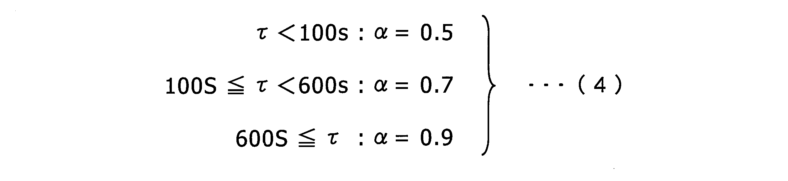
- the weighting value ⁇ can be determined based on a parameter value that is a function type of the first model function 26 and a parameter value that is a function type coefficient of the second model function 27. As an example of the determination of the weight value ⁇ , it can be determined according to the time constant ⁇ when the open circuit voltage rises with time. As described above, when the time constant ⁇ is large, the first model function 26 is preferably applied to estimate the stable value of the open circuit voltage. When the time constant ⁇ is small, the second model function 27 is applied. It is preferable. Therefore, the weighting value ⁇ can be determined according to the equation (4).
- the weighting value ⁇ is fixed, but may be determined in consideration of the type of battery 3, the environmental temperature, the amount of current during charging / discharging, the SOC value, the predicted time t S, and the like. it can. It can also be determined by learning. For example, learning can be performed using data collected in advance using a machine learning method such as a neural network, and the weighted value ⁇ can be calculated using the learned model.
- the weighting value ⁇ is determined in S7, the most probable open circuit voltage stability is obtained using the predicted value V S1 calculated by the first model function 26 and the predicted value V S2 calculated by the second model function 27 in S6.
- FIG. 5 shows the stable estimated value V S0 using the weighting value ⁇ .
- the SOC of the battery 3 after the discharge is completed can be calculated using the relationship between the open circuit voltage and the SOC obtained in advance (S9). ).
- the open circuit voltage is estimated by sampling the voltage between the terminals of the battery 3 after charging and discharging, the calculation of the SOC based on the voltage can be calculated in a shorter time than before.
- the open circuit voltage is estimated by using multiple model functions used for prediction and weighting between them, it is possible to flexibly cope with the behavior of the open circuit voltage that varies in a complex manner under various conditions, and the estimation accuracy is improved. .
- weighting is performed using two predicted values based on two model functions.
- N weighted values ⁇ 1 to ⁇ are used.
- N can be used to weight according to equation (5).
- the sum of N weighting values 1.
- the open circuit voltage is estimated based on the actual measurement values obtained in one measurement period after the end of charge / discharge, but this is performed for several measurement periods and the results are updated sequentially. By doing so, estimation accuracy can be improved.
- 1 battery charge / discharge control system 2 battery charge / discharge unit, 3 battery, 4 discharge load, 5 charge power supply, 6 current detection unit, 7 voltage detection unit, 8 charge / discharge control device, 10 battery state estimation device, 11 storage unit, 12 commercial power supply, 13 solar cell, 14 charger, 20 actual measurement value acquisition unit, 21 model function determination unit, 22 multiple prediction unit, 23 estimation unit, 25 model function file, 26 first model function, 27 second model function, 30 (first model function) function form, 31 (second model function) function form.
Landscapes
- Physics & Mathematics (AREA)
- General Physics & Mathematics (AREA)
- Engineering & Computer Science (AREA)
- Manufacturing & Machinery (AREA)
- Chemical & Material Sciences (AREA)
- Chemical Kinetics & Catalysis (AREA)
- Electrochemistry (AREA)
- General Chemical & Material Sciences (AREA)
- Secondary Cells (AREA)
- Charge And Discharge Circuits For Batteries Or The Like (AREA)
- Tests Of Electric Status Of Batteries (AREA)
Abstract
Description



図5は、図4の推定安定値算出の様子を示す図である。

Claims (5)
- 充放電を行った電池に対し、時間と共に変化する電池状態を予め定めた計測期間について実測値を取得する実測値取得部と、
前記電池状態をモデル化する複数のモデル関数の関数形を前記実測値によって決定するモデル関数決定部と、
前記関数形が決定された前記複数のモデル関数のそれぞれについて前記電池状態の変化を予測する複数予測部と、
前記複数予測部の結果に基づき、前記電池状態の推定安定値を算出する推定部と、
を備える、電池状態推定装置。 - 請求項1に記載の電池状態推定装置において、
前記複数のモデル関数は、
前記電池状態が時間に関し指数関数的に変化する第1モデル関数と、
前記電池状態が時間に関し対数関数的に変化する第2モデル関数と、
を少なくとも含む、電池状態推定装置。 - 請求項1または2に記載の電池状態推定装置において、
前記推定部は、
前記複数の予測結果を、前記決定されたモデル関数の係数に基づいて定められた重みづけで加算して前記電池状態の推定安定値を算出する、電池状態推定装置。 - 請求項1に記載の電池状態推定装置において、
前記電池状態は、電池の開回路電圧である、電池状態推定装置。 - 請求項4に記載の電池状態推定装置において、
前記電池状態は、前記電池の開回路電圧に基づいて算出される電池の充電状態である、電池状態推定装置。
Priority Applications (3)
| Application Number | Priority Date | Filing Date | Title |
|---|---|---|---|
| JP2014559589A JP6234946B2 (ja) | 2013-02-01 | 2014-01-31 | 電池状態推定装置 |
| US14/764,153 US20150369875A1 (en) | 2013-02-01 | 2014-01-31 | Battery state estimating device |
| CN201480006820.XA CN104956233B (zh) | 2013-02-01 | 2014-01-31 | 电池状态推断装置 |
Applications Claiming Priority (2)
| Application Number | Priority Date | Filing Date | Title |
|---|---|---|---|
| JP2013-017981 | 2013-02-01 | ||
| JP2013017981 | 2013-02-01 |
Publications (1)
| Publication Number | Publication Date |
|---|---|
| WO2014119328A1 true WO2014119328A1 (ja) | 2014-08-07 |
Family
ID=51262042
Family Applications (1)
| Application Number | Title | Priority Date | Filing Date |
|---|---|---|---|
| PCT/JP2014/000511 Ceased WO2014119328A1 (ja) | 2013-02-01 | 2014-01-31 | 電池状態推定装置 |
Country Status (4)
| Country | Link |
|---|---|
| US (1) | US20150369875A1 (ja) |
| JP (1) | JP6234946B2 (ja) |
| CN (1) | CN104956233B (ja) |
| WO (1) | WO2014119328A1 (ja) |
Cited By (3)
| Publication number | Priority date | Publication date | Assignee | Title |
|---|---|---|---|---|
| WO2017056732A1 (ja) * | 2015-09-30 | 2017-04-06 | 日立オートモティブシステムズ株式会社 | 電池制御装置及び電池システム |
| JP2018040676A (ja) * | 2016-09-07 | 2018-03-15 | 日立化成株式会社 | 車載用蓄電デバイスモデルのパラメータ同定方法及びパラメータ同定装置 |
| JP2018169183A (ja) * | 2017-03-29 | 2018-11-01 | 株式会社豊田自動織機 | 蓄電装置及び開回路電圧推定方法 |
Families Citing this family (18)
| Publication number | Priority date | Publication date | Assignee | Title |
|---|---|---|---|---|
| FR3006450B1 (fr) * | 2013-06-04 | 2015-05-22 | Renault Sa | Procede pour estimer l'etat de sante d'une cellule electrochimique de stockage d'energie electrique |
| JP6326452B2 (ja) * | 2016-06-15 | 2018-05-16 | 本田技研工業株式会社 | 電池状態推定装置および電池状態推定方法 |
| DE112017004259T5 (de) * | 2016-08-26 | 2019-05-16 | Kabushiki Kaisha Toyota Jidoshokki | Leistungsspeichervorrichtung |
| KR101912615B1 (ko) | 2017-04-20 | 2018-10-29 | 이정환 | 배터리 모니터링 및 보호 시스템 |
| US11598812B2 (en) | 2018-11-15 | 2023-03-07 | Lear Corporation | Methods and systems for performing diagnostic processes with reduced processing time |
| CN110118937A (zh) * | 2019-05-13 | 2019-08-13 | 深圳江行联加智能科技有限公司 | 自适应预测模型的蓄电池荷电状态边缘计算优化检测方法 |
| TWI718783B (zh) * | 2019-11-28 | 2021-02-11 | 新普科技股份有限公司 | 以視覺化圖像建立電池狀態模型的方法 |
| CN113495213B (zh) * | 2020-03-20 | 2025-02-21 | 北京京东乾石科技有限公司 | 电量预测模型构建、搬运设备部署方法和装置 |
| CN111564877A (zh) * | 2020-04-30 | 2020-08-21 | 华为技术有限公司 | 用于充电管控的方法和装置 |
| US20210349155A1 (en) | 2020-05-07 | 2021-11-11 | Zitara Technologies, Inc. | Battery analysis system and method |
| TWI741632B (zh) * | 2020-06-03 | 2021-10-01 | 龍華科技大學 | 電池智能分流模組之電阻溫度係數預測方法、電流量測補償校正方法及其裝置 |
| DE102020215890A1 (de) * | 2020-12-15 | 2022-06-15 | Robert Bosch Gesellschaft mit beschränkter Haftung | Verfahren und Vorrichtung zur Vorhersage eines Alterungszustands eines Energiespeicher-Systems |
| JP2022157734A (ja) * | 2021-03-31 | 2022-10-14 | 本田技研工業株式会社 | 劣化状態推定システム、劣化状態推定方法、及びプログラム |
| JP2022157740A (ja) * | 2021-03-31 | 2022-10-14 | 本田技研工業株式会社 | 状態推定システム、状態推定方法、及びプログラム |
| US11774504B2 (en) | 2021-10-04 | 2023-10-03 | Zitara Technologies, Inc. | System and method for battery management |
| WO2023107710A2 (en) | 2021-12-09 | 2023-06-15 | Zitara Technologies, Inc. | System and method for determining a battery condition |
| US12571853B2 (en) * | 2022-02-17 | 2026-03-10 | Battelle Energy Alliance, Llc | Predicting aging of batteries |
| EP4792150A1 (en) | 2023-10-11 | 2026-08-19 | Fortescue Zero Limited | System and method for degradation based battery control |
Citations (3)
| Publication number | Priority date | Publication date | Assignee | Title |
|---|---|---|---|---|
| WO2006129802A1 (ja) * | 2005-06-03 | 2006-12-07 | The Furukawa Electric Co., Ltd. | 充電率/残存容量推定方法、電池の状態検知センサ及び電池電源システム |
| JP2007121227A (ja) * | 2005-10-31 | 2007-05-17 | Yazaki Corp | バッテリの開回路電圧推定方法および装置 |
| JP2008256436A (ja) * | 2007-04-03 | 2008-10-23 | Yazaki Corp | 近似式算出装置及びその方法、並びに、バッテリ状態監視装置 |
Family Cites Families (5)
| Publication number | Priority date | Publication date | Assignee | Title |
|---|---|---|---|---|
| US6646419B1 (en) * | 2002-05-15 | 2003-11-11 | General Motors Corporation | State of charge algorithm for lead-acid battery in a hybrid electric vehicle |
| JP4984527B2 (ja) * | 2005-12-27 | 2012-07-25 | トヨタ自動車株式会社 | 二次電池の充電状態推定装置および充電状態推定方法 |
| JP4649682B2 (ja) * | 2008-09-02 | 2011-03-16 | 株式会社豊田中央研究所 | 二次電池の状態推定装置 |
| US8207706B2 (en) * | 2009-08-04 | 2012-06-26 | Honda Motor Co., Ltd. | Method of estimating battery state of charge |
| US20130030738A1 (en) * | 2011-01-19 | 2013-01-31 | Sendyne Corporation | Converging algorithm for real-time battery prediction |
-
2014
- 2014-01-31 JP JP2014559589A patent/JP6234946B2/ja active Active
- 2014-01-31 CN CN201480006820.XA patent/CN104956233B/zh active Active
- 2014-01-31 US US14/764,153 patent/US20150369875A1/en not_active Abandoned
- 2014-01-31 WO PCT/JP2014/000511 patent/WO2014119328A1/ja not_active Ceased
Patent Citations (3)
| Publication number | Priority date | Publication date | Assignee | Title |
|---|---|---|---|---|
| WO2006129802A1 (ja) * | 2005-06-03 | 2006-12-07 | The Furukawa Electric Co., Ltd. | 充電率/残存容量推定方法、電池の状態検知センサ及び電池電源システム |
| JP2007121227A (ja) * | 2005-10-31 | 2007-05-17 | Yazaki Corp | バッテリの開回路電圧推定方法および装置 |
| JP2008256436A (ja) * | 2007-04-03 | 2008-10-23 | Yazaki Corp | 近似式算出装置及びその方法、並びに、バッテリ状態監視装置 |
Cited By (4)
| Publication number | Priority date | Publication date | Assignee | Title |
|---|---|---|---|---|
| WO2017056732A1 (ja) * | 2015-09-30 | 2017-04-06 | 日立オートモティブシステムズ株式会社 | 電池制御装置及び電池システム |
| JPWO2017056732A1 (ja) * | 2015-09-30 | 2018-03-22 | 日立オートモティブシステムズ株式会社 | 電池制御装置及び電池システム |
| JP2018040676A (ja) * | 2016-09-07 | 2018-03-15 | 日立化成株式会社 | 車載用蓄電デバイスモデルのパラメータ同定方法及びパラメータ同定装置 |
| JP2018169183A (ja) * | 2017-03-29 | 2018-11-01 | 株式会社豊田自動織機 | 蓄電装置及び開回路電圧推定方法 |
Also Published As
| Publication number | Publication date |
|---|---|
| JP6234946B2 (ja) | 2017-11-22 |
| US20150369875A1 (en) | 2015-12-24 |
| JPWO2014119328A1 (ja) | 2017-01-26 |
| CN104956233B (zh) | 2018-04-03 |
| CN104956233A (zh) | 2015-09-30 |
Similar Documents
| Publication | Publication Date | Title |
|---|---|---|
| JP6234946B2 (ja) | 電池状態推定装置 | |
| KR102885238B1 (ko) | 배터리 상태를 추정하는 전자 장치 및 그 동작 방법 | |
| Chen et al. | A new state-of-health estimation method for lithium-ion batteries through the intrinsic relationship between ohmic internal resistance and capacity | |
| KR102156404B1 (ko) | 배터리 셀 성능 테스트 장치 및 방법 | |
| CN110914696B (zh) | 用于在电池的操作期间估计电池开路池格电压、充电状态以及健康状态的方法和系统 | |
| US10447046B2 (en) | Secondary battery management system with remote parameter estimation | |
| US10001528B1 (en) | Battery deterioration degree estimating apparatus and estimating method | |
| KR102373458B1 (ko) | 배터리를 위한 등가 회로 모델의 파라미터 추정 방법 및 배터리 관리 시스템 | |
| KR102869898B1 (ko) | 배터리 상태 추정 방법 및 장치 | |
| JP6738836B2 (ja) | 効率的なバッテリーテスター | |
| JP5058814B2 (ja) | バッテリーの状態及びパラメーターの推定システム及び方法 | |
| CN113785209B (zh) | 用于检测异常电池单体的方法 | |
| US20170115355A1 (en) | Maximum capacity estimator for battery state of health and state of charge determinations | |
| TW201702623A (zh) | 用於測定鋰硫電池之健康狀態及充電狀態的方法及裝置 | |
| KR102416548B1 (ko) | 배터리를 위한 등가 회로 모델의 파라미터 추정 방법 및 배터리 관리 시스템 | |
| CN117222904A (zh) | 电池状态推定装置、电力系统 | |
| KR20200097170A (ko) | 배터리 관리 장치, 배터리 관리 방법 및 배터리팩 | |
| KR102465373B1 (ko) | 배터리 관리 장치, 배터리 관리 방법 및 배터리팩 | |
| CN112912745A (zh) | 根据开路电压图形确定电化学电池的充电状态和老化状态的方法 | |
| WO2023238636A1 (ja) | 製造方法、製造装置及びプログラム | |
| KR20200085575A (ko) | 배터리 팩의 최대 허용 전력을 결정하기 위한 장치 및 방법 | |
| JP5851514B2 (ja) | 電池制御装置、二次電池システム | |
| CN114814604B (zh) | 一种电池soc估算方法及装置 | |
| Sandrabyna et al. | State-of-Charge Estimation for LiFePO4 Batteries with Adaptive State Update in Specific OCV Ranges Using Adaptive Extended Kalman Filter | |
| KR20240108760A (ko) | 배터리 수명 추정 장치 및 방법 |
Legal Events
| Date | Code | Title | Description |
|---|---|---|---|
| 121 | Ep: the epo has been informed by wipo that ep was designated in this application |
Ref document number: 14746620 Country of ref document: EP Kind code of ref document: A1 |
|
| ENP | Entry into the national phase |
Ref document number: 2014559589 Country of ref document: JP Kind code of ref document: A |
|
| WWE | Wipo information: entry into national phase |
Ref document number: 14764153 Country of ref document: US |
|
| NENP | Non-entry into the national phase |
Ref country code: DE |
|
| 122 | Ep: pct application non-entry in european phase |
Ref document number: 14746620 Country of ref document: EP Kind code of ref document: A1 |