WO2014115751A1 - 超音波診断装置 - Google Patents
超音波診断装置 Download PDFInfo
- Publication number
- WO2014115751A1 WO2014115751A1 PCT/JP2014/051224 JP2014051224W WO2014115751A1 WO 2014115751 A1 WO2014115751 A1 WO 2014115751A1 JP 2014051224 W JP2014051224 W JP 2014051224W WO 2014115751 A1 WO2014115751 A1 WO 2014115751A1
- Authority
- WO
- WIPO (PCT)
- Prior art keywords
- image
- display
- ultrasonic
- probe
- cross
- Prior art date
- Legal status (The legal status is an assumption and is not a legal conclusion. Google has not performed a legal analysis and makes no representation as to the accuracy of the status listed.)
- Ceased
Links
Images










Classifications
-
- A—HUMAN NECESSITIES
- A61—MEDICAL OR VETERINARY SCIENCE; HYGIENE
- A61B—DIAGNOSIS; SURGERY; IDENTIFICATION
- A61B8/00—Diagnosis using ultrasonic, sonic or infrasonic waves
- A61B8/52—Devices using data or image processing specially adapted for diagnosis using ultrasonic, sonic or infrasonic waves
- A61B8/5207—Devices using data or image processing specially adapted for diagnosis using ultrasonic, sonic or infrasonic waves involving processing of raw data to produce diagnostic data, e.g. for generating an image
-
- A—HUMAN NECESSITIES
- A61—MEDICAL OR VETERINARY SCIENCE; HYGIENE
- A61B—DIAGNOSIS; SURGERY; IDENTIFICATION
- A61B8/00—Diagnosis using ultrasonic, sonic or infrasonic waves
- A61B8/42—Details of probe positioning or probe attachment to the patient
- A61B8/4245—Details of probe positioning or probe attachment to the patient involving determining the position of the probe, e.g. with respect to an external reference frame or to the patient
- A61B8/4254—Details of probe positioning or probe attachment to the patient involving determining the position of the probe, e.g. with respect to an external reference frame or to the patient using sensors mounted on the probe
-
- A—HUMAN NECESSITIES
- A61—MEDICAL OR VETERINARY SCIENCE; HYGIENE
- A61B—DIAGNOSIS; SURGERY; IDENTIFICATION
- A61B8/00—Diagnosis using ultrasonic, sonic or infrasonic waves
- A61B8/13—Tomography
- A61B8/14—Echo-tomography
-
- A—HUMAN NECESSITIES
- A61—MEDICAL OR VETERINARY SCIENCE; HYGIENE
- A61B—DIAGNOSIS; SURGERY; IDENTIFICATION
- A61B8/00—Diagnosis using ultrasonic, sonic or infrasonic waves
- A61B8/42—Details of probe positioning or probe attachment to the patient
- A61B8/4245—Details of probe positioning or probe attachment to the patient involving determining the position of the probe, e.g. with respect to an external reference frame or to the patient
-
- A—HUMAN NECESSITIES
- A61—MEDICAL OR VETERINARY SCIENCE; HYGIENE
- A61B—DIAGNOSIS; SURGERY; IDENTIFICATION
- A61B8/00—Diagnosis using ultrasonic, sonic or infrasonic waves
- A61B8/46—Ultrasonic, sonic or infrasonic diagnostic devices with special arrangements for interfacing with the operator or the patient
- A61B8/461—Displaying means of special interest
-
- A—HUMAN NECESSITIES
- A61—MEDICAL OR VETERINARY SCIENCE; HYGIENE
- A61B—DIAGNOSIS; SURGERY; IDENTIFICATION
- A61B8/00—Diagnosis using ultrasonic, sonic or infrasonic waves
- A61B8/46—Ultrasonic, sonic or infrasonic diagnostic devices with special arrangements for interfacing with the operator or the patient
- A61B8/461—Displaying means of special interest
- A61B8/463—Displaying means of special interest characterised by displaying multiple images or images and diagnostic data on one display
-
- A—HUMAN NECESSITIES
- A61—MEDICAL OR VETERINARY SCIENCE; HYGIENE
- A61B—DIAGNOSIS; SURGERY; IDENTIFICATION
- A61B8/00—Diagnosis using ultrasonic, sonic or infrasonic waves
- A61B8/46—Ultrasonic, sonic or infrasonic diagnostic devices with special arrangements for interfacing with the operator or the patient
- A61B8/461—Displaying means of special interest
- A61B8/466—Displaying means of special interest adapted to display 3D data
-
- A—HUMAN NECESSITIES
- A61—MEDICAL OR VETERINARY SCIENCE; HYGIENE
- A61B—DIAGNOSIS; SURGERY; IDENTIFICATION
- A61B8/00—Diagnosis using ultrasonic, sonic or infrasonic waves
- A61B8/46—Ultrasonic, sonic or infrasonic diagnostic devices with special arrangements for interfacing with the operator or the patient
- A61B8/467—Ultrasonic, sonic or infrasonic diagnostic devices with special arrangements for interfacing with the operator or the patient characterised by special input means
-
- A—HUMAN NECESSITIES
- A61—MEDICAL OR VETERINARY SCIENCE; HYGIENE
- A61B—DIAGNOSIS; SURGERY; IDENTIFICATION
- A61B8/00—Diagnosis using ultrasonic, sonic or infrasonic waves
- A61B8/46—Ultrasonic, sonic or infrasonic diagnostic devices with special arrangements for interfacing with the operator or the patient
- A61B8/467—Ultrasonic, sonic or infrasonic diagnostic devices with special arrangements for interfacing with the operator or the patient characterised by special input means
- A61B8/469—Ultrasonic, sonic or infrasonic diagnostic devices with special arrangements for interfacing with the operator or the patient characterised by special input means for selection of a region of interest
-
- A—HUMAN NECESSITIES
- A61—MEDICAL OR VETERINARY SCIENCE; HYGIENE
- A61B—DIAGNOSIS; SURGERY; IDENTIFICATION
- A61B8/00—Diagnosis using ultrasonic, sonic or infrasonic waves
- A61B8/54—Control of the diagnostic device
-
- A—HUMAN NECESSITIES
- A61—MEDICAL OR VETERINARY SCIENCE; HYGIENE
- A61B—DIAGNOSIS; SURGERY; IDENTIFICATION
- A61B8/00—Diagnosis using ultrasonic, sonic or infrasonic waves
- A61B8/48—Diagnostic techniques
- A61B8/483—Diagnostic techniques involving the acquisition of a 3D volume of data
Definitions
- Embodiments of the present invention relate to an ultrasonic diagnostic apparatus.
- an ultrasonic diagnostic apparatus has output from a position sensor such as a magnetic sensor, an X-ray computed tomography (hereinafter referred to as CT) apparatus, and a magnetic resonance imaging (hereinafter referred to as MRI).
- CT computed tomography
- MRI magnetic resonance imaging
- a position sensor such as a magnetic sensor, an X-ray computed tomography (hereinafter referred to as CT) apparatus, and a magnetic resonance imaging (hereinafter referred to as MRI).
- CT X-ray computed tomography
- MRI magnetic resonance imaging
- An ultrasonic diagnostic apparatus having a dual display function designates a specific position through an operation by an operator using position information from a position sensor.
- the ultrasonic diagnostic apparatus has a guide function for executing a guide from the cross section during scanning to the specific position in accordance with the distance between the cross section during scanning and the specific position and the direction perpendicular to the scan cross section.
- the ultrasonic diagnostic apparatus having a guide function can be guided to a position related to a scanning section including a specific position.
- a plurality of scanning cross-section candidates are, for example, a cross-section capable of grasping the travel position of a lumen such as a blood vessel and a bile duct located around the treatment target region, and a tissue when the treatment target region is close to the boundary of the tissue to be treated. It is a cross section which can grasp
- the operator is required to have a high technique for reproducing the same scanning section again among the plurality of confirmed scanning sections.
- an ultrasonic diagnostic apparatus having a dual display function has an image processing function such as surface rendering using three-dimensional image data relating to a number of modalities, and position information as support for recognizing the position of an ultrasonic scanning section in a three-dimensional space.
- an image processing function such as surface rendering using three-dimensional image data relating to a number of modalities, and position information as support for recognizing the position of an ultrasonic scanning section in a three-dimensional space.
- FIG. 22 is a diagram illustrating an example of a conventional three-dimensional body mark.
- the 3D body mark can indicate to the operator the relative position of the ultrasonic probe with respect to the subject.
- the position where the ultrasonic probe is brought into contact with the subject cannot be efficiently guided to the position of the ultrasonic probe related to the scanning section desired by the operator only by displaying the three-dimensional body mark. That is, to display again the cross section desired by the operator depends on the memory of the operator and the skill of the operator. For this reason, the reproducibility of the cross section desired by the operator has a problem that takes time.
- the conventional ultrasonic diagnostic apparatus can display a B-mode image that is substantially the same as the B-mode image stored in the past by ultrasonic scanning.
- substantially identical image display in order to display a plurality of cross-sectional images according to other modalities with respect to the displayed B-mode image including the specific position.
- the input operation for displaying a plurality of screens by other modalities must be performed while maintaining the probe position. For this reason, in addition to the cumbersome operation, a case where the display cross section is displaced occurs.
- the conventional ultrasonic diagnostic apparatus when substantially the same image display is executed, when generating another B-mode image including a specific position, such as a vertical section, or various software relating to ultrasonic diagnosis
- a specific position such as a vertical section
- various software relating to ultrasonic diagnosis When an image is activated or when an annotation related to a cross-sectional image is displayed on the displayed B-mode image, an input operation such as an additional operation or a change in scanning conditions is required, and the probe position is changed as described above.
- a desired cross section cannot be displayed while being held. That is, there is a problem that the operator is troublesome to perform the input operation while maintaining the cross section.
- the purpose is to display guide information for quickly moving the ultrasonic probe to a position corresponding to the ultrasonic image desired by the operator.
- the display content and the scanning mode are displayed.
- An object of the present invention is to provide an ultrasonic diagnostic apparatus capable of realizing changing and executing a predetermined image display function. For example, an object is to efficiently guide an ultrasonic probe to an optimal treatment section after scanning (surveying) a subject immediately before treatment on the subject. It is another object of the present invention to continuously perform an action desired by an operator without losing the guided scanning section.
- the ultrasonic diagnostic apparatus includes an ultrasonic probe that transmits ultrasonic waves to a subject and receives a reflected wave from the subject, and a position detection unit that detects a probe position related to the ultrasonic probe.
- An ultrasonic image generation unit that generates an ultrasonic image based on the received reflected wave; a storage unit that stores the volume data acquired with respect to the subject and the specified position specified by the operator in association with each other; , Based on the volume data and the specified position, a cross-sectional image generator that generates a scanning cross-sectional image corresponding to the specified position, a first display that displays the scanning cross-sectional image and the ultrasonic image,
- a display unit that displays at least one of a second display that displays different display content from the display content in the first display, and the probe position detected by the position detection unit There triggered that it has moved to a range corresponding to the designated position, comprising a control unit for controlling the switching to the second display from the first display.
- guide information for quickly moving the ultrasonic probe to a position corresponding to the ultrasonic image desired by the operator is displayed, and when the position of the ultrasonic probe reaches the above position, the display content is displayed.
- an ultrasonic diagnostic apparatus capable of changing the scanning mode and executing a predetermined image display function.
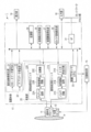
- FIG. 1 is a configuration diagram illustrating an example of the configuration of the ultrasonic diagnostic apparatus according to the first embodiment.
- FIG. 2 is a schematic diagram illustrating an example of an outline related to generation of probe guide information according to the first embodiment.
- FIG. 3 is a diagram illustrating an example of display of probe guide information according to the first embodiment.
- FIG. 4 is a diagram illustrating an example of a display screen that displays an ultrasonic image and a corresponding cross-sectional image together with a three-dimensional body mark image according to the first embodiment.
- FIG. 5 is a diagram illustrating an example of a display screen when an ultrasonic image is bookmarked according to the first embodiment.
- FIG. 6 is a diagram illustrating an example of a display screen when the third ultrasonic image is bookmarked according to the first embodiment.
- FIG. 7 is a diagram illustrating an example of a display screen when a thumbnail image is designated according to the first embodiment.
- FIG. 8 is a diagram illustrating an example in which probe guide information is superimposed on an ultrasound image in the first display according to the first embodiment.
- FIG. 9 is a diagram illustrating an example in which probe guide information and a display frame of a scanning cross-sectional image are superimposed on an ultrasound image in the first display according to the first embodiment.
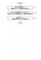
- FIG. 10 is a diagram illustrating an example of a flowchart illustrating a procedure of processing related to the probe guide information display function according to the first embodiment.
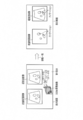
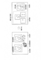
- FIG. 11 relates to the first modification of the first embodiment, and the display content is switched from the first display to the second display when the probe position moves to a predetermined range corresponding to the designated position. It is a figure which shows an example of a display screen.
- FIG. 12 relates to a first modification of the first embodiment, and the display content is changed from the first display to the display of the coincidence superimposed image when the probe position moves to a predetermined range corresponding to the designated position. It is a figure which shows an example of the switched display screen.
- FIG. 13 relates to a first modification of the first embodiment, and changes the display content from the first display to the display of the annotation superimposed image when the probe position moves to a predetermined range corresponding to the designated position. It is a figure which shows an example of the switched display screen.
- FIG. 14 relates to a first modification of the first embodiment, and the display content of the display screen is changed from the first display to the second display when the probe position moves to a predetermined range corresponding to the designated position. It is a figure which shows an example of the flowchart of the procedure switched to.
- FIG. 15 is a flowchart illustrating an example of a procedure for changing the scanning mode when the probe position has moved to a predetermined range corresponding to the designated position, according to the second modification of the first embodiment.
- FIG. FIG. 16 is a configuration diagram illustrating an example of a configuration of an ultrasonic diagnostic apparatus according to the second embodiment.
- FIG. 17 is a diagram illustrating an example of a display of an insertion path of a puncture needle on an ultrasound image when the probe position is moved to a predetermined range corresponding to the specified position according to the second embodiment.
- FIG. 18 is a diagram illustrating an example in which a marker related to a predetermined measurement is displayed on an ultrasonic image when the probe position has moved to a predetermined range corresponding to the specified position according to the second embodiment.
- FIG. 19 relates to the second embodiment, and an example of a display in which a predetermined tissue region in an ultrasonic image in the second display is extracted when the probe position moves to a predetermined range corresponding to the designated position.
- FIG. 20 is a flowchart illustrating an example of an image display processing procedure according to the second embodiment.
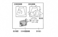
- FIG. 21 is a diagram relating to the display of two cross-sectional images with different modalities according to the related art.
- FIG. 22 is a diagram related to a conventional three-dimensional body mark.
- FIG. 1 shows a block diagram of an ultrasonic diagnostic apparatus 1 according to this embodiment.
- the ultrasonic diagnostic apparatus 1 is connected to an ultrasonic probe 11, a position sensor 13, a position detector 15, an apparatus main body 17, and an apparatus main body 17, and receives various instructions / commands / information from an operator.
- An input unit 18 and a display unit 19 for taking in the main body 17 are provided.
- a biological signal measurement unit and a network represented by an electrocardiograph, a heart sound meter, a pulse wave meter, and a respiration sensor are referred to as an interface (hereinafter referred to as I / F). ) 31 may be connected.
- the ultrasonic probe 11 has a plurality of piezoelectric vibrators, a matching layer, and a backing material provided on the back side of the plurality of piezoelectric vibrators.
- the plurality of piezoelectric vibrators are acoustic / electric reversible conversion elements such as piezoelectric ceramics.
- the plurality of piezoelectric vibrators are arranged in parallel and are provided at the tip of the ultrasonic probe 11. Hereinafter, description will be made assuming that one piezoelectric vibrator constitutes one channel.
- the piezoelectric vibrator generates an ultrasonic wave in response to a drive signal supplied from the scanning unit 20 described later.
- the transmitted ultrasonic wave (hereinafter referred to as a transmitted ultrasonic wave) is reflected by a discontinuous surface of acoustic impedance in the living tissue in the subject. Is done.
- the piezoelectric vibrator receives the reflected ultrasonic wave (reflected wave) and generates an echo signal.
- the amplitude of the echo signal depends on the difference in acoustic impedance with the discontinuous surface regarding the reflection of the ultrasonic wave as a boundary.
- the frequency of the echo signal when the transmitted ultrasonic wave is reflected by the moving blood flow and the surface of the heart wall, etc. is transmitted by the Doppler effect. It shifts depending on the velocity component of the direction.
- the ultrasonic probe 11 will be described as a probe that performs two-dimensional scanning with a one-dimensional array.
- the ultrasonic probe 11 may be a mechanical four-dimensional probe that performs three-dimensional scanning by swinging a one-dimensional array in a direction orthogonal to the arrangement direction of a plurality of transducers. Further, the ultrasonic probe 11 is not limited to a mechanical four-dimensional probe, and may be a two-dimensional array probe.
- the matching layer is provided on the ultrasonic radiation surface side of the plurality of piezoelectric vibrators in order to efficiently transmit / receive ultrasonic waves to / from the subject P.
- the backing material prevents the propagation of ultrasonic waves to the back of the piezoelectric vibrator.
- the position sensor 13 acquires position information of the ultrasonic probe 11 with reference to a predetermined reference position.
- the position information includes coordinate information indicating the position of the ultrasonic probe 11 with respect to a predetermined reference position and angle information regarding the angle of the ultrasonic probe 11.
- the angle information is, for example, the inclination of the ultrasonic probe 11 with respect to a predetermined reference axis.
- the predetermined reference position is, for example, the position of the apparatus main body 17 of the ultrasonic diagnostic apparatus 1.
- the reference position may be provided outside the apparatus main body 17.
- the predetermined reference axis is, for example, by two of three orthogonal axes set in advance and a straight line (hereinafter referred to as a probe axis) connecting the opening center of the ultrasonic probe 11 and the center of gravity of the ultrasonic probe 11. It is prescribed.
- the two axes are an x axis and ay axis among preset three orthogonal axes (x axis, y axis, z axis).
- the position sensor 13 is provided in the ultrasonic probe 11, for example. The position sensor 13 outputs the acquired position information to the position detection unit 15 described later.
- the position sensor 13 is, for example, a magnetic sensor, an infrared sensor, an angle sensor (for example, a gyro sensor) or the like.
- the magnetic sensor acquires coordinate information based on a predetermined reference position using magnetism transmitted from a magnetic transmitter (not shown) in the position detector 15.
- the infrared sensor acquires coordinate information with a predetermined reference position as a reference, using infrared rays transmitted from an infrared transmitter (not shown) in the position detector 15.
- a general electromagnetic wave may be used instead of infrared rays.
- the reference position may be the position of the magnetic transmitter.
- the reference position may be the position of an infrared transmitter. Further, the reference position can be adjusted as appropriate according to an instruction from the operator via the input unit 18 described later. Note that the predetermined reference position may be a position that first contacts the body surface of the subject.
- the angle sensor acquires angle information of the ultrasonic probe 11 around a predetermined reference axis.
- the detected angle is based on the positions of two points output from two magnetic sensors, two infrared sensors, or a combination of a magnetic sensor and an infrared sensor provided on the side surface of the ultrasonic probe 11. May be acquired.
- the position detector 15 uses the position information output from the position sensor 13 to detect a three-dimensional coordinate indicating the position of the ultrasonic probe 11 with respect to a predetermined reference position and an angle around the predetermined reference axis.
- the detected three-dimensional coordinates and angle are collectively referred to as a probe position.
- the position detection unit 15 determines a three-dimensional coordinate indicating the position of the ultrasonic probe 11 and an angle around the reference axis on an absolute coordinate system based on a predetermined reference position.
- the position detection unit 15 outputs the probe position to a CPU 33 and a guide information generation unit 25 described later.
- the apparatus main body 17 includes a scanning unit 20, an ultrasonic image generation unit 22, a guide information generation unit 25, a cross-sectional image generation unit 27, a storage unit 29, an I / F 31, a control processor (central processing unit: Central Processing Unit: hereinafter CPU (Referred to as a “control unit”) 33.
- CPU Central Processing Unit
- the scanning unit 20 generates a drive signal for driving each of the plurality of transducers in the ultrasonic probe 11.
- the scanning unit 20 supplies a drive signal to each of the plurality of vibrators.
- the scanning unit 20 generates a reception signal based on the reception echo signal generated by each of the plurality of transducers.
- the scanning unit 20 includes an ultrasonic transmission unit 210 and an ultrasonic reception unit 220.
- the ultrasonic transmission unit 210 includes a trigger generation circuit 21A, a transmission delay circuit 21B, and a pulsar circuit 21C.
- the ultrasonic reception unit 220 includes a preamplifier circuit 22A, a reception delay circuit 22B, and an adder 22C.
- the trigger generation circuit 21A repeatedly generates a rate pulse for forming a transmission ultrasonic wave at a predetermined rate frequency frHz (cycle: 1 / fr second).
- the trigger generation circuit 21A repeatedly generates rate pulses at a predetermined rate frequency. This rate pulse is distributed to the channels and sent to the transmission delay circuit 21B.
- the transmission delay circuit 21B for each of a plurality of channels, sets a delay time (hereinafter referred to as a transmission delay time) necessary for converging transmission ultrasonic waves in a beam shape and determining transmission directivity to each rate pulse. give.
- the transmission direction or transmission delay time of transmission ultrasonic waves (hereinafter referred to as a transmission delay pattern) is stored in the storage unit 29 described later.
- the transmission delay pattern stored in the storage unit 29 is referred to by the CPU 33 when transmitting an ultrasonic wave.
- the rate pulse to which the delay time is given is sent to the pulser circuit 21C described later.
- the pulser circuit 21C applies a voltage pulse (drive signal) to each of the plurality of piezoelectric vibrators of the ultrasonic probe 11 at a timing based on this rate pulse. Thereby, an ultrasonic beam is transmitted to the subject.
- the echo signal reflected by the biological tissue of the subject is taken in for each channel as a reception echo signal via the ultrasonic probe 11.
- the preamplifier circuit 22A amplifies the reception echo signal from the subject taken in via the ultrasonic probe 11 for each channel.
- An analog-digital converter (not shown) converts the amplified received echo signal into a digital signal.
- the reception delay circuit 22B gives a delay time (hereinafter referred to as reception delay time) necessary for determining the reception directivity to the reception echo signal converted into the digital signal.
- reception delay time The reception direction or reception delay time of the echo signal (hereinafter referred to as a reception delay pattern) is stored in the storage unit 29.
- the reception delay pattern stored in the storage unit 29 is referred to by the CPU 33.
- the adder 22C adds a plurality of echo signals given delay times.
- the ultrasonic reception unit 220 generates a reception signal (also referred to as an RF (radiofrequency) signal) in which a reflection component from a direction corresponding to the reception directivity is emphasized.
- the overall directivity of ultrasonic transmission / reception is determined by the transmission directivity and the reception directivity. This total directivity determines the ultrasonic beam (so-called “ultrasonic scanning line”).
- the ultrasonic reception unit 220 outputs a reception signal for each depth in each scanning line in the scanned region to the B-mode data generation unit 21 or the Doppler data generation unit 23 described later.
- the ultrasonic receiving unit 220 may have a parallel receiving function of simultaneously receiving echo signals generated on a plurality of scanning lines by one ultrasonic transmission.
- the ultrasonic image generation unit 22 includes a B-mode data generation unit 21, a Doppler data generation unit 23, a digital scan converter (Digital Scan Converter: hereinafter referred to as DSC), an image memory, and an image synthesis device.
- DSC Digital Scan Converter
- the B-mode data generation unit 21 has an envelope detector, a logarithmic converter, etc., not shown.
- the envelope detector performs envelope detection on the reception signal output from the scanning unit 20.
- the envelope detector outputs the envelope-detected signal to a logarithmic converter described later.
- the logarithmic converter relatively emphasizes a weak signal by logarithmically converting the envelope-detected signal.
- the B mode data generation unit 21 generates a signal value (B mode data) for each depth in each scanning line based on the signal emphasized by the logarithmic converter.
- the B-mode data generation unit 21 has an envelope detector, a logarithmic converter, etc., not shown.
- the envelope detector performs envelope detection on the reception signal output from the scanning unit 20.
- the envelope detector outputs the envelope-detected signal to a logarithmic converter.
- the logarithmic converter relatively emphasizes a weak signal by logarithmically converting the envelope-detected signal.
- the B mode data generation unit 21 generates a signal value (B mode data) for each depth in each scanning line and each ultrasonic wave transmission / reception based on the signal emphasized by the logarithmic converter.
- the B-mode data generation unit 21 performs an azimuth (Azimuth) direction, an elevation (Elevation) direction, and a depth in a scanned region.
- Three-dimensional B-mode data composed of a plurality of signal values arranged in association with each direction (hereinafter referred to as a range direction) may be generated.
- the range direction is the depth direction on the scanning line.
- the azimuth direction is, for example, an electronic scanning direction along the arrangement direction of the one-dimensional ultrasonic transducers.
- the elevation direction is the mechanical oscillation direction of the one-dimensional ultrasonic transducer.
- the three-dimensional B-mode data may be data in which a plurality of pixel values or a plurality of luminance values are arranged in association with the azimuth direction, the elevation direction, and the range direction along the scanning line. .
- the three-dimensional B-mode data may be data relating to ROI set in advance in the scanned region.
- the B mode data generation unit 21 may generate ultrasonic volume data instead of the three-dimensional B mode data.
- the data generated by the B-mode data generation unit 21 are collectively referred to as B-mode data.
- the B mode data generating unit 21 uses the probe position detected by the position detecting unit 15 to associate the B mode data with the absolute coordinate system.
- the B-mode data generation unit 21 may associate the probe position with the three-dimensional B-mode data.
- the Doppler data generation unit 23 includes a mixer, a low-pass filter (hereinafter referred to as LPF), a speed / dispersion / Power arithmetic device, etc., not shown.
- the mixer multiplies the reception signal output from the scanning unit 20 by a reference signal having the same frequency f 0 as the transmission frequency. By this multiplication, a signal having a component of Doppler shift frequency f d and a signal having a frequency component of (2f 0 + f d ) are obtained.
- the LPF removes a signal having a high frequency component (2f 0 + f d ) from signals having two types of frequency components from the mixer.
- the Doppler data generation unit 23 may use a quadrature detection method in order to generate a Doppler signal.
- the received signal RF signal
- the received signal is quadrature detected and converted to an IQ signal.
- Doppler data generating unit 23 by the complex Fourier transform of the IQ signal, for generating a Doppler signal having a component of the Doppler shift frequency f d.
- the Doppler signal is, for example, a Doppler component due to blood flow, tissue, or contrast medium.
- the speed / dispersion / Power calculation device includes an MTI (Moving Target Indicator) filter, an LPF filter, an autocorrelation calculator, etc., not shown.
- a cross-correlation calculator may be provided instead of the autocorrelation calculator.
- the MTI filter removes Doppler components (clutter components) caused by respiratory movement or pulsatile movement of the organ from the generated Doppler signal.
- the MTI filter is used to extract a Doppler component related to blood flow (hereinafter referred to as a blood flow Doppler component) from the Doppler signal.
- the LPF is used to extract a Doppler component related to tissue movement (hereinafter referred to as a tissue Doppler component) from the Doppler signal.
- the autocorrelation calculator calculates autocorrelation values for blood flow Doppler components and tissue Doppler components. Based on the calculated autocorrelation value, the autocorrelation calculator calculates an average velocity value, a variance value, a reflection intensity (power) of the Doppler signal, and the like of the blood flow and the tissue.
- the velocity / dispersion / power calculation device generates color Doppler data at each position in a predetermined region based on blood flow and tissue average velocity values based on a plurality of Doppler signals, dispersion values, reflection intensity of Doppler signals, and the like.
- Doppler signals and color Doppler data are collectively referred to as Doppler data.
- the Doppler data may be three-dimensional data (hereinafter referred to as three-dimensional Doppler data).
- the three-dimensional Doppler data and the three-dimensional B-mode data are collectively referred to as three-dimensional ultrasonic data.
- the ultrasonic image generator 22 generates a B-mode image based on the B-mode data generated by the B-mode data generator 21.
- the ultrasonic image generation unit 22 generates a Doppler image based on the Doppler data generated by the Doppler data generation unit 23.
- the B-mode image and the Doppler image are collectively referred to as an ultrasonic image. That is, the ultrasonic image generation unit 22 generates an ultrasonic image based on the data output from the scanning unit 20.
- the ultrasonic image generation unit 22 performs coordinate conversion processing (resampling) on the DSC.
- the coordinate conversion process is, for example, a process of converting an ultrasonic scan scanning line signal sequence including B-mode data and Doppler data into a scanning line signal sequence of a general video format represented by a television or the like.
- the ultrasonic image generation unit 22 generates an ultrasonic image as a display image by coordinate conversion processing.
- the ultrasonic image generator 22 generates a B-mode image based on the B-mode data.
- the ultrasonic image generation unit 22 generates a Doppler image such as an average velocity image, a dispersion image, or a power image based on the Doppler data.
- the image memory stores data (hereinafter referred to as image data) corresponding to the generated ultrasonic image (B-mode image, average velocity image, distributed image, power image).
- image data data corresponding to the generated ultrasonic image
- the image data stored in the image memory is read out according to an operator instruction via the input unit 18.
- the image memory is, for example, a memory that stores ultrasonic images corresponding to a plurality of frames immediately before freezing. It is also possible to display the ultrasonic moving image on the display unit 19 by continuously displaying the images stored in the cine memory (cine display).
- the image synthesizing device synthesizes character information, scales, and the like of various parameters with the ultrasonic image and the scanning cross-sectional image described later.
- the image composition device outputs the synthesized image to the display unit 19.
- the guide information generating unit 25 generates probe guide information based on the probe position and a designated position described later.
- the probe guide information is information displayed on the display unit 19 as a guide when the operator moves the ultrasonic probe 11 to a specified position, for example.
- the guide information generating unit 25 updates the probe guide information with the movement of the probe position.
- the guide information generating unit 25 stores a program for generating probe guide information (hereinafter referred to as a guide information generating program) in a memory (not shown).
- a guide information generating program a program for generating probe guide information
- the guide information generation unit 25 Expands to its own memory.
- the guide information generation unit 25 generates probe guide information by operating the guide information generation program with the probe position and the designated position as inputs.
- the guide information generation unit 25 is a probe based on the position corresponding to the specified cross section related to the thumbnail image specified by the input unit 18 and displayed on the display unit 19 and the probe position detected by the position detection unit 15. Generate guide information.
- the position corresponding to the designated cross section is, for example, a position that defines the cross section in the absolute coordinate system and a probe position related to acquisition of an ultrasonic image corresponding to the cross section.
- the guide information generating unit 25 may store a correspondence table of probe guide information with respect to probe positions and designated positions in a memory (not shown). At this time, when a thumbnail designation operation is executed, the guide information generation unit 25 may generate probe guide information based on the probe position, the specified position, and the correspondence table.
- the guide information generation unit 25 sets the designated thumbnail image.
- the probe position (designated position) related to the corresponding ultrasonic image (at the time of acquisition) is read from the storage unit 29.
- the guide information generation unit 25 reads the probe position related to the ultrasonic probe 11 being scanned from the position detection unit 15 in response to the thumbnail designation operation.
- the guide information generating unit 25 uses the reference position as a reference to determine the distance between the designated position and the probe position (hereinafter, guide Called the distance).
- the guide information generation unit 25 determines a direction from the probe position to the specified position (hereinafter referred to as a guide direction) based on the designated position read from the storage unit 29 and the probe position read from the position detection unit 15. Specifically, the guide information generating unit 25 calculates the guide distance and the guide direction using the three-dimensional coordinates at the designated position with respect to the reference position and the three-dimensional coordinates at the probe position.
- the guide information generation unit 25 determines the rotation angle of the ultrasonic probe 11 based on the designated position read from the storage unit 29 and the probe position read from the position detection unit 15. Specifically, the guide information generating unit 25 determines the rotation angle of the ultrasonic probe 11 (hereinafter referred to as the guide rotation angle) based on the angle around the reference axis at the designated position and the angle around the reference axis at the probe position. Called). Specifically, the guide information generation unit 25 calculates the absolute value of the angle difference between the angle at the designated position and the angle at the probe position as the guide rotation angle for each of the plurality of reference axes.
- the probe guide information is a guide distance, a guide direction, and a guide rotation angle.
- FIG. 2 is a schematic diagram showing an example of an outline regarding generation of probe guide information.
- the probe position is, for example, the coordinates (x0, y0, z0) of the opening center with respect to the reference position and the angle ( ⁇ 0, ⁇ 0, ⁇ 0) in the reference axis (x axis, y axis, probe axis).
- the designated position has, for example, coordinates (x0, y0, z0) of the opening center with respect to the reference position and angles ( ⁇ 0, ⁇ 0, ⁇ 0) on the reference axis (x axis, y axis, probe axis).
- the guide distance is calculated by ((x1-x0) ⁇ 2 + (y1-y0) ⁇ 2 + (z1-z0) ⁇ 2) ⁇ (1/2).
- the guide direction is determined by calculating a direction vector from the probe position to the designated position, for example.
- the guide rotation angle around the Z axis among the guide rotation angles is determined by calculating
- the guide rotation angle around the x-axis among the guide rotation angles is determined by calculating
- the guide rotation angle around the probe axis among the guide rotation angles is determined by calculating
- FIG. 3 is a diagram illustrating an example of display of probe guide information. As shown in FIG. 3, the probe guide information is displayed on the display unit 19 together with a schematic diagram (probe mark) regarding the ultrasonic probe 11.
- the calculation formula of the probe guide information shown in FIG. 3 is stored in a memory (not shown) of the guide information generating unit 25 as, for example, a guide information generating program or a correspondence table.
- the cross-sectional image generation unit 27 performs an operation (hereinafter referred to as a dual display operation) for displaying a cross-sectional image corresponding to an ultrasonic image (hereinafter referred to as a corresponding cross-sectional image) and an ultrasonic image in parallel via the input unit 18.
- a corresponding cross-sectional image is generated based on the volume data stored in the storage unit 29 and the probe position.
- the corresponding cross-sectional image includes a scanned region related to the ultrasonic image.
- the cross-sectional image generation unit 27 After the input of the dual display operation, the cross-sectional image generation unit 27 generates a corresponding cross-sectional image corresponding to the ultrasonic image updated according to the movement of the ultrasonic probe 11. That is, the cross-sectional position of the corresponding cross-sectional image and the ultrasonic image substantially coincide.
- the cross-sectional image generation unit 27 generates a three-dimensional body mark image indicating the probe mark and the scanned region based on the probe position. The scanned region is superimposed on the body mark in a translucent or opaque state. Note that the cross-sectional image generation unit 27 may generate a three-dimensional body mark image based on the volume data and the probe position, for example, by surface rendering processing or volume rendering processing. The cross-sectional image generation unit 27 outputs data related to the ultrasonic image, the corresponding cross-sectional image, and the three-dimensional body mark image to the display unit 19.
- the cross-sectional image generation unit 27 When a bookmark instruction (hereinafter referred to as a bookmark instruction) is input via the input unit 18, the cross-sectional image generation unit 27 performs a bookmark image based on an ultrasound image (hereinafter referred to as a bookmark image) relating to the bookmark instruction.
- a thumbnail image of the corresponding cross-sectional image corresponding to is generated.
- the cross-sectional image generation unit 27 outputs the generated thumbnail image to the display unit 19.
- the input unit 18 may input a cross section designated by the operator in the volume data.
- the cross-sectional image generation unit 27 generates a thumbnail image corresponding to the input cross-section.
- the thumbnail image is a thumbnail image of the corresponding cross-sectional image, for example, an image obtained by reducing the corresponding cross-sectional image.
- the thumbnail image may be an image obtained by resizing the corresponding cross-sectional image to the size of the thumbnail and correcting the resolution to the same level as the corresponding cross-sectional image.
- the cross-sectional image generation unit 27 When the thumbnail specifying operation is executed, the cross-sectional image generation unit 27 superimposes the probe guide information generated by the guide information generation unit 25 on the three-dimensional body mark image (hereinafter referred to as a 3DBM superimposed image). appear.
- the scanned area related to the designated position in the 3DBM superimposed image may be superimposed on the three-dimensional body mark in a translucent or opaque state.
- the cross-sectional image generation unit 27 outputs the 3DBM superimposed image to the display unit 19. Note that the cross-sectional image generation unit 27 updates the 3DBM superimposed image in accordance with the movement of the probe position.
- the cross-sectional image generation unit 27 generates a thumbnail image related to the position corresponding to the cross-section designated via the input unit 18 based on the volume data or the ultrasonic image. Specifically, the cross-sectional image generation unit 27 uses a position that defines a specified cross-section based on volume data or an ultrasonic image, or a probe position at the time of acquisition of an ultrasonic image including the specified cross-section. Then, a thumbnail image relating to the position corresponding to the designated cross section is generated. The cross-sectional image generation unit 27 outputs the generated thumbnail image to the display unit 19.
- the storage unit 29 includes a plurality of reception delay patterns having different focus depths, a plurality of transmission delay patterns, various data groups such as a device control program, diagnostic protocol, and transmission / reception conditions of the ultrasonic diagnostic apparatus 1, diagnostic information (patient ID, doctor Observation), received signal generated by the scanning unit 20, B-mode data generated by the B-mode data generating unit 21, Doppler data generated by the Doppler data generating unit 23, ultrasound image (B-mode image, average) Speed image, dispersion image, power image) and the like are stored.
- the storage unit 29 stores the volume data of the subject acquired in the past by other modalities.
- the volume data is obtained from another modality (for example, an X-ray computed tomography apparatus, a magnetic resonance imaging apparatus, etc.) capable of generating volume data or a medical image storage apparatus (not shown) via the I / F 31 and the network.
- the data is transferred to the storage unit 29 of the apparatus main body 17.
- the volume data is data generated by an X-ray computed tomography apparatus.
- the storage unit 29 outputs volume data to the cross-sectional image generation unit 27.
- the volume data may be data generated by the ultrasonic diagnostic apparatus 1.
- the storage unit 29 stores the corresponding cross-sectional image and the ultrasonic image (bookmark image) displayed on the monitor in association with the probe position.
- the probe position related to the ultrasonic image to which the bookmark instruction is input corresponds to the above-described designated position.
- the corresponding cross-sectional image to be stored includes a scanned region related to the designated position.
- the corresponding cross-sectional image stored by the bookmark instruction is referred to as a scanning cross-sectional image. That is, the thumbnail image is a thumbnail of the scanning slice image.
- the storage unit 29 may store the volume data and the position corresponding to the cross section designated via the input unit 18 in association with each other.
- the storage unit 29 stores a three-dimensional body mark, a probe mark, a marker indicating a scanned region, and the like.
- the storage unit 29 outputs a three-dimensional body mark, a probe mark, a marker indicating the scanned region, and the like to the cross-sectional image generation unit 27.
- the storage unit 29 may store a guide information generation program.
- the storage unit 29 outputs a guide information generation program to the guide information generation unit 25 in response to an input of a thumbnail designation operation.
- the storage unit 29 outputs the scanning slice image to the display unit 19 in response to the thumbnail designation operation.
- the storage unit 29 stores a predetermined range.
- the predetermined range is used by the CPU 33 in order to determine that the designated position and the probe position substantially coincide.
- the predetermined range is, for example, a range within a predetermined distance from the specified position.
- the predetermined range is a range including the designated position and the guide distance being substantially zero.
- the predetermined range is, for example, a range where the guide rotation angle is substantially zero. That is, the predetermined range is a range for defining a range where the designated position and the probe position substantially coincide.
- the storage unit 29 may store a predetermined threshold instead of the predetermined range. At this time, the predetermined threshold is a value at which the guide distance and the guide rotation angle are substantially zero.
- the I / F 31 is an interface related to a network, an external storage device (not shown), and a biological signal measurement unit. Data such as ultrasonic images obtained by the apparatus main body 17 and analysis results can be transferred to other apparatuses via the I / F 31 and the network.
- the CPU 33 determines the transmission delay pattern stored in the storage unit 29 based on the selection for the B mode and the Doppler mode, the frame rate, the scanned depth, the transmission start / end, and the like input by the operator via the input unit 18.
- the reception delay pattern and the device control program are read out, and the device main body 17 is controlled according to these.
- the CPU 33 controls the storage unit 29 and the cross-sectional image generation unit 27 in order to generate a corresponding cross-sectional image.
- the CPU 33 controls the display unit 19 to display the ultrasonic image and the corresponding cross-sectional image in parallel.
- the CPU 33 stores the bookmark image and the corresponding cross-sectional image in association with the probe position in order to store them. To control. At this time, the CPU 33 controls the cross-sectional image generation unit 27 in order to generate a thumbnail image of the scanning cross-sectional image corresponding to the bookmark image.
- the CPU 33 controls the guide information generation unit 25 and the cross-sectional image generation unit 27 in order to generate a 3DBM superimposed image. Further, the CPU 33 causes the scanning unit image to be output from the storage unit 29 to the display unit 19 in response to the thumbnail specifying operation. In addition, the CPU 33 controls the display unit 19 to display the ultrasonic image and the scanning cross-sectional image generated in real time in parallel with the thumbnail designation operation. The CPU 33 controls the display unit 19 to display the 3DBM superimposed image together with the ultrasonic image and the scanning cross-sectional image generated in real time in response to the thumbnail designation operation.
- the display of the scanning cross-sectional image, the ultrasonic image generated in real time, and the 3DBM superimposed image with the thumbnail designation operation as an opportunity is referred to as a first display.
- the CPU 33 reads a predetermined range from the storage unit 29 in response to the thumbnail designation operation.
- the CPU 33 displays a predetermined display for transmitting the movement matching to the operator.
- the display unit 19 is controlled to display (hereinafter, referred to as movement matching display) on the display screen of the monitor of the display unit 19.
- the movement matching display is, for example, a character or icon for making the operator recognize movement matching.
- the CPU 33 may change at least one of the hue, lightness, and saturation of the probe mark in the 3DBM superimposed image to make it easy for the operator to recognize the movement match in response to the movement match.
- the CPU 33 may output a predetermined voice or the like via an output unit (not shown) triggered by movement matching.
- the predetermined voice is a voice for causing the operator to recognize the movement match.
- the CPU 33 may control the display unit 19 in order to cancel the display of the 3DBM superimposed image in the first display in response to the movement match.
- the input unit 18 is connected to the apparatus main body 17 and takes in various instructions, commands, information, selections, and settings from the operator into the apparatus main body 17.
- the input unit 18 includes input devices such as a trackball, a switch button, a mouse, and a keyboard (not shown).
- the input device detects the coordinates of the cursor displayed on the display screen, and outputs the detected coordinates to the CPU 33.
- the input device may be a touch panel provided to cover the display screen. In this case, the input unit 18 detects coordinates instructed by a touch reading principle such as an electromagnetic induction type, an electromagnetic distortion type, and a pressure sensitive type, and outputs the detected coordinates to the CPU 33. Further, when the operator operates the end button or the freeze button of the input unit 18, the transmission / reception of the ultrasonic waves is ended, and the apparatus main body 17 is temporarily stopped.
- the input unit 18 may designate a cross section of the subject according to an instruction from the operator. Specifically, the input unit 18 designates a cross section for volume data or an ultrasonic image. The input unit 18 outputs a position corresponding to the designated cross section to the storage unit 29. The input unit 18 designates a thumbnail image displayed on the display unit 19 according to an instruction from the operator.
- the input unit 18 includes a dual display button for executing dual display, a bookmark button for inputting a bookmark instruction, a dial for selecting a plurality of thumbnail images displayed on the display unit 19, a trackball, and a display screen Has a cursor displayed above. Further, the input unit 18 may have a determination button for designating the selected thumbnail image.
- the bookmark button may be provided as a touch panel that covers the display screen of the display unit 19.
- the input unit 18 moves the cursor displayed on the monitor of the display unit 19 by operating a trackball or a mouse, for example, on one thumbnail image among a plurality of thumbnail images displayed on the display screen of the display unit 19. Move.
- the input unit 18 specifies a thumbnail image located behind the cursor by pressing the enter button.
- the input unit 18 is provided with a dial having a push switch, one thumbnail image is selected from the plurality of thumbnail images by rotating the dial. At this time, when a push switch provided on the dial is pressed, the selected thumbnail image is designated.
- the display unit 19 has a monitor (not shown).
- the display unit 19 displays various images generated by the ultrasonic image generation unit 22 and the cross-sectional image generation unit 27 on the monitor.
- the display unit 19 may perform adjustments such as brightness, contrast, dynamic range, and ⁇ correction, and color map assignment for various images. Specifically, when the dual display operation is executed, the display unit 19 displays the corresponding cross-sectional image and the ultrasonic image in parallel, and also displays the three-dimensional body mark image.
- the display unit 19 may display a thumbnail image related to the position corresponding to the designated cross section. When a thumbnail image is designated via the input unit 18, the display unit 19 displays probe guide information.
- the display unit 19 may display the probe guide information together with at least one of the thumbnail image and the ultrasonic image.
- FIG. 4 is a diagram showing a display example of a display screen in which the corresponding cross-sectional image and the ultrasonic image are displayed in parallel and the three-dimensional body mark image is displayed.
- the display unit 19 may display the corresponding cross-sectional image and the ultrasonic image in parallel, and may display a three-dimensional body mark image and a bookmark button.
- FIG. 5 is a diagram illustrating a display example of a display screen in which an ultrasonic image and a corresponding cross-sectional image are displayed in parallel and a three-dimensional body mark image, a bookmark button, and a thumbnail image A are displayed.
- the display unit 19 further displays a plurality of thumbnail images respectively corresponding to the plurality of bookmark instructions.
- FIG. 6 is a diagram illustrating a display example of a display screen in which an ultrasonic image and a corresponding cross-sectional image are displayed in parallel, and a three-dimensional body mark image, a bookmark button, and a plurality of thumbnail images (A, B, C) are displayed. is there.
- the display unit 19 replaces the corresponding cross-sectional image with the scanning cross-sectional image corresponding to the designated thumbnail image, and displays the thumbnail cross-section image as a trigger. In addition, the display unit 19 replaces the three-dimensional body mark image with a 3DBM superimposed image. The display unit 19 highlights the display frame of the designated thumbnail image.
- FIG. 7 is a diagram showing an example in which a plurality of thumbnail images are displayed together with the first display. In the display of FIG. 7, the display unit 19 updates and displays the probe guide information in the 3DBM superimposed image according to the movement of the ultrasonic probe 11. If there is no room for displaying the probe guide information on the display screen, the display unit 19 may hide the probe guide information such as the numerical values of the angle and the distance in FIG.
- the display unit 19 displays a movement matching display triggered by movement matching. At the same time, the display unit 19 replaces the scanning cross-sectional image with the original corresponding cross-sectional image, and displays the movement cross-section. Note that the display unit 19 may cancel the display of the probe guide information in the displayed 3DBM image in response to the movement match. The display unit 19 may display the thumbnail image together with the ultrasonic image and the guide information.
- the display unit 19 may display the probe guide information superimposed on the ultrasound image when the thumbnail designation operation is executed.
- FIG. 8 is a diagram illustrating an example of a display screen in which probe guide information is superimposed on an ultrasound image in the first display.
- the display unit 19 may display a display frame of the scanning slice image corresponding to the thumbnail image so as to be superimposed on the ultrasonic image in the first display.
- FIG. 9 is a diagram showing an example of a display screen in which the probe guide information and the display frame of the scanning slice image are superimposed and displayed on the ultrasonic image in the first display. The shape of the display frame is determined based on the designated position and the probe position by the guide information generating unit 25, for example.
- the display unit 19 can also display a three-dimensional body mark image corresponding to a plurality of angles at the probe position.
- the display unit 19 can fix the probe position during scanning on the three-dimensional body mark image and display the three-dimensional body mark image by rotating it by a predetermined angle.
- the probe guide information display function is a function for displaying a 3DBM superimposed image indicating a probe position and a designated position together with a scanning cross-sectional image corresponding to a designated thumbnail image and an ultrasonic image being scanned.
- probe guide information display processing processing related to the probe guide information display function
- FIG. 10 is a diagram illustrating an example of a flowchart illustrating a procedure of probe guide information display processing.
- a corresponding cross-sectional image is generated based on the probe position relating to the ultrasonic image being scanned and the volume data stored in the storage unit 29 (step Sa1).
- the generated corresponding cross-sectional image and the ultrasonic image being scanned are displayed in parallel (step Sa2). If no bookmark instruction is input via the input unit 18 (step Sa3), the processes of step Sa1 and step Sa2 are repeated.
- the ultrasonic image corresponding to the probe position and the corresponding cross-sectional image are repeatedly displayed on the display screen of the monitor in the display unit 19 according to the movement of the ultrasonic probe 11.
- step Sa3 When a bookmark instruction is input via the input unit 18 (bookmark button is pressed) (step Sa3), the bookmark image and the corresponding cross-sectional image (scanning cross-sectional image) corresponding to the bookmark image are stored together with the probe position (designated position). Stored in the unit 29 (step Sa4). At this time, a thumbnail image of the scanning slice image is generated and displayed on the display screen of the monitor in the display unit 19. Until a thumbnail image is designated via the input unit 18 (input of a thumbnail designation operation), the processing from step Sa1 to step Sa4 is repeated (step Sa5). At this time, a plurality of thumbnail images corresponding to a plurality of depressions of the bookmark button are displayed.
- the scanning cross-sectional image corresponding to the thumbnail image and the designated position are read from the storage unit 29.
- the read scanning sectional image is displayed together with the ultrasonic image being scanned (step Sa6).
- Probe guide information is generated based on the designated position and the probe position corresponding to the ultrasonic image being scanned.
- a 3DBM superimposed image in which the probe guide information is superimposed on the three-dimensional body mark image is generated and displayed (step Sa8).
- the ultrasonic probe 11 is moved (step Sa9).
- step Sa10 If there is no probe position within a predetermined range including the designated position (step Sa10), new probe guide information is generated based on the probe position and designated position relating to the moved ultrasonic probe 11 (step Sa11). ). Next, the probe guide information in the 3DBM superimposed image is updated (step Sa12).
- step Sa10 If there is a probe position within a predetermined range including the designated position (step Sa10), a movement matching display is displayed (step Sa13). If another thumbnail image is selected after the process of step Sa13, the processes of step Sa6 to step Sa13 are repeated.
- the difference from the first embodiment is that when the probe position is moved within a predetermined range including the designated position, a plurality of cross-sectional images related to the designated position are generated based on the designated position and the volume data.
- the purpose is to display a plurality of cross-sectional images together with the ultrasonic image being scanned.
- This modification has a plurality of processes following step Sa13 of the probe guide information display process in the first embodiment.
- the cross-sectional image generation unit 27 generates a plurality of cross-sectional images including a cross-section having a position different from the cross-section of the scanning cross-sectional image based on the designated position and the volume data, triggered by movement matching. Specifically, the cross-sectional image generating unit 27 generates a plurality of MPR images obtained by performing cross-sectional transformation (hereinafter referred to as MPR) on the scanned cross-sectional image as a plurality of cross-sectional images. Further, the cross-sectional image generation unit 27 may generate a coincidence superimposed image obtained by superimposing the ultrasonic image being scanned on the scanning cross-sectional image in response to the movement coincidence. The cross-sectional image generation unit 27 may read an annotation related to the scanning cross-sectional image from the storage unit 29, and generate an annotation superimposed image in which the read annotation is superimposed on the ultrasonic image being scanned.
- MPR cross-sectional transformation
- the display unit 19 displays a plurality of MPR images together with the ultrasonic image being scanned, triggered by movement matching.
- the display of a plurality of MPR images and the ultrasonic image being scanned is referred to as a second display.
- the second display may further include a Doppler image.
- the display part 19 may display a coincidence superimposition image triggered by movement coincidence.
- the display unit 19 may display the annotation superimposed image in response to the movement match.
- the display unit 19 may display at least one of the first display and the second display.
- the CPU 33 controls the display unit 19 in order to switch the display of the monitor on the display unit 19 from the first display to the second display in response to the movement match. Note that the CPU 33 may control the display unit 19 in order to switch the display of the monitor from the first display to the display of the coincidence superimposed image in response to the movement coincidence. Further, the CPU 33 may control the display unit 19 in order to switch the monitor display from the first display to the coincidence superimposed image triggered by the movement coincidence.
- FIG. 11 is a diagram illustrating an example of a display screen in which the display content is switched from the first display to the second display in response to movement matching. As shown in FIG. 11, in the present modification, the display content on the display screen is switched from the first display to the second display, triggered by movement matching.
- FIG. 12 is a diagram illustrating an example of a display screen in which the display content is switched from the first display to the display of the coincidence superimposed image in response to the movement match.
- FIG. 13 is a diagram illustrating an example of a display screen in which the display content is switched from the first display to the display of the annotation superimposed image in response to the movement match.
- the display switching function is a function that switches the display content of the display screen from the first display to the second display when the probe position enters a predetermined range including the designated position (movement match).
- display switching processing processing related to the display switching function
- FIG. 14 is a diagram illustrating an example of a flowchart illustrating a procedure of display switching processing.
- the probe position is moved within a predetermined range including the designated position (step Sb1).
- a plurality of cross-sectional images (MPR images) are generated based on the volume data and the designated position (step Sb2).
- the CPU 33 controls the switching of the display content on the display screen from the first display to the second display (step Sb3).
- a plurality of generated cross-sectional images (MPR images) are displayed together with the ultrasonic image being scanned (step Sb4).
- This modification has a plurality of processes following step Sa13 of the probe guide information display process in the first embodiment.
- a mechanical four-dimensional probe or a two-dimensional array probe that performs three-dimensional scanning by swinging a one-dimensional array in a direction orthogonal to the arrangement direction of a plurality of transducers is used as the ultrasonic probe 11.
- the storage unit 29 stores a plurality of scanning modes.
- the plurality of scanning modes stores a two-dimensional scanning mode in which the subject is scanned in two dimensions and a three-dimensional scanning mode in which the subject is scanned in three dimensions.
- the storage unit 29 stores a plurality of reception delay patterns, a plurality of transmission delay patterns, and a device control program with different focus depths regarding the two-dimensional scanning mode.
- the storage unit 29 stores a plurality of reception delay patterns having different focus depths, a plurality of transmission delay patterns, and an apparatus control program regarding the three-dimensional scanning mode.
- the CPU 33 controls the scanning unit 20 in order to change from the two-dimensional scanning mode to the three-dimensional scanning mode in response to the movement coincidence. Specifically, the CPU 33 controls the scanning unit 20 to execute the two-dimensional scanning mode until the probe position is moved within a predetermined range including the designated position. When the probe position is moved within a predetermined range including the designated position or the position corresponding to the designated cross section, the CPU 33 scans the scanning unit 20 to change the scanning mode from the two-dimensional scanning mode to the three-dimensional scanning mode. To control. That is, the CPU 33 controls the scanning unit 20 so as to execute the three-dimensional scanning mode after the probe position is moved into a predetermined range including the designated position.
- the CPU 33 controls the scanning unit 20 to generate three-dimensional ultrasonic data by three-dimensional scanning on the subject.
- the CPU 33 controls the cross-sectional image generation unit 27 to generate a plurality of ultrasound images respectively corresponding to the plurality of MPR images based on the three-dimensional ultrasound data and the plurality of MPR images based on the movement match. To do.
- the CPU 33 controls the display unit 19 to display a plurality of MPR images and a plurality of ultrasonic images, triggered by movement matching.
- the scanning unit 20 scans the subject according to the scanning mode set by the CPU 33. Specifically, when the two-dimensional scanning mode is set, the scanning unit 20 performs ultrasonic two-dimensional scanning on the subject. When the three-dimensional scanning mode is set, the scanning unit 20 performs ultrasonic three-dimensional scanning (volume scanning) on the subject. The scanning unit 20 generates three-dimensional ultrasound data by volume scanning on the subject.
- the cross-sectional image generation unit 27 generates a plurality of ultrasonic images respectively corresponding to the plurality of MPR images based on the three-dimensional volume data and the plurality of MPR images, triggered by movement matching.
- the display unit 19 displays a plurality of ultrasonic images respectively corresponding to a plurality of MPR images, triggered by movement matching.
- the scanning mode changing function is a function for changing the ultrasound scanning mode for the subject when the probe position is moved within a predetermined range including a designated position or a position corresponding to a designated cross section.
- scanning mode changing processing processing related to the scanning mode changing function
- FIG. 15 is a diagram illustrating an example of a flowchart illustrating a procedure of scanning mode switching processing.
- the subject is scanned in the two-dimensional scanning mode (step Sc1).
- a corresponding cross-sectional image is generated based on the probe position relating to the ultrasonic image being scanned and the volume data stored in the storage unit 29.
- the generated corresponding cross-sectional image and the ultrasonic image being scanned are displayed in parallel.
- a bookmark instruction is input via the input unit 18 (the bookmark button is pressed)
- the bookmark image and the corresponding cross-sectional image (scanning cross-sectional image) corresponding to the bookmark image are stored in the storage unit 29 together with the probe position (designated position). Is done.
- a thumbnail image of the scanning slice image is generated and displayed on the display screen of the monitor in the display unit 19.
- a scanning cross-sectional image corresponding to the thumbnail image and a specified position (or a position corresponding to the specified cross-section) are read from the storage unit 29. It is.
- the read scanning sectional image is displayed together with the ultrasonic image being scanned (step Sc2).
- Probe guide information is generated based on the designated position (or the position corresponding to the designated cross section) and the probe position corresponding to the ultrasonic image being scanned.
- a 3DBM superimposed image in which probe guide information is superimposed on the three-dimensional body mark image is generated and displayed.
- the ultrasonic probe 11 is moved (step Sc3).
- step Sc4 If there is no probe position within a predetermined range including the designated position (or the position corresponding to the designated cross section) (step Sc4), the probe position and the designated position (or the designated cross section) relating to the moved ultrasonic probe 11
- the probe guide information is newly generated on the basis of (the position corresponding to).
- the probe guide information in the 3DBM superimposed image is updated. Subsequently, the processes of step Sc2 and step Sc3 are executed.
- the ultrasound scanning mode for the subject is changed from the two-dimensional scanning mode to the three-dimensional scanning mode. (Step Sc5).
- the subject is scanned in the three-dimensional scanning mode (step Sc6).
- a plurality of slice images (MPR images) are generated based on the volume data and the designated position (or a position corresponding to the designated slice) (step Sc7).
- a plurality of ultrasound images respectively corresponding to the plurality of MPR images are generated (step Sc8).
- a plurality of cross-sectional images are displayed together with a plurality of ultrasonic images (step Sc9).
- the ultrasonic diagnostic apparatus 1 of the present embodiment has a probe guide information display function for displaying again an ultrasonic image stored in advance by the operator.
- the ultrasonic diagnostic apparatus 1 based on difference information between a designated position of a stored ultrasonic image (a position (coordinate) in a three-dimensional space and a three-axis rotation direction) and a probe position during scanning in real time. Probe guide information can be generated and displayed.
- an operator can be directly guided to a designated position related to a desired scanning section. That is, according to the ultrasonic diagnostic apparatus 1, the position where the ultrasonic probe 11 is brought into contact with the subject can be efficiently guided to the position of the ultrasonic probe related to the scanning section desired by the operator.
- the probe position when the probe position is moved within a predetermined range including the designated position, a plurality of cross-sectional images related to the designated position are generated based on the designated position and the volume data.
- a plurality of generated cross-sectional images can be displayed together with the ultrasonic image being scanned. That is, according to the first modification, the display content displayed on the display screen can be changed from the first display to the second display with the movement match as a trigger. Thereby, when the ultrasonic image substantially coincides with the scanning slice image, a plurality of slice images can be displayed.
- the ultrasound scanning mode for the subject triggered by movement matching it is possible to change the ultrasound scanning mode for the subject triggered by movement matching.
- a plurality of ultrasonic images respectively corresponding to a plurality of cross-sectional images (MPR images) in the second display can be generated.
- the ultrasonic diagnostic apparatus According to the ultrasonic diagnostic apparatus 1, the position where the ultrasonic probe 11 is brought into contact with the subject is set to the designated position (or the position corresponding to the designated cross section). Can be efficiently guided. Further, according to the ultrasonic diagnostic apparatus 1, the display content displayed on the display screen can be changed from the first display to the second display in response to the movement match. In addition, according to the ultrasonic diagnostic apparatus 1, it is possible to change the scanning mode of the ultrasonic wave with respect to the subject, triggered by movement matching. For these reasons, according to the present ultrasonic diagnostic apparatus, the diagnostic efficiency of the operator for the subject is improved.
- the difference from the first embodiment is that a program related to a predetermined image display processing function (hereinafter referred to as an image processing program) is started when the probe position is moved within a predetermined range including a designated position.
- the purpose is to execute predetermined image processing.
- FIG. 16 is a configuration diagram illustrating an example of a configuration of an ultrasonic diagnostic apparatus according to the second embodiment.
- the ultrasonic diagnostic apparatus further includes an image display processing unit 35 in addition to the units in the ultrasonic diagnostic apparatus 1 according to the first embodiment.
- the storage unit 29 stores a predetermined image processing program.
- the storage unit 29 outputs a predetermined image processing program to the image display processing unit 35 described later, triggered by the movement match.
- the image display processing unit 35 has an image display processing function for executing a predetermined image display process for a plurality of images in the second display, triggered by movement matching. Specifically, the image display processing unit 35 superimposes the insertion path of the puncture needle on the ultrasonic image in the second display triggered by movement matching.
- the insertion path of the puncture needle may be input via the input unit 18 in advance, for example.
- the image display processing unit 35 superimposes a predetermined measurement tool on the ultrasonic image in the second display, triggered by movement matching. Specifically, the image display processing unit 35 superimposes a marker related to a predetermined measurement (hereinafter referred to as a measurement marker) on a predetermined tissue region in the ultrasonic image of the second display.
- the measurement marker is, for example, a caliper for measuring the distance between two points on the ultrasonic image, a marker for measuring the area in the measurement marker, or the like.
- the image display processing unit 35 can also superimpose the measurement result related to the measurement marker displayed on the ultrasonic image on the second display.
- the image display processing unit 35 stores a predetermined extraction threshold value related to the region extraction processing in a memory (not shown).
- the image display processing unit 35 executes a region extraction process (segmentation process) on the ultrasonic image in the second display using a predetermined extraction threshold, triggered by movement matching.
- the image display processing unit 35 superimposes and displays the segmentation processing result on the ultrasonic image in the second display.
- the display unit 19 displays an image on which a predetermined image display process has been performed on a plurality of images in the second display, triggered by movement matching. Specifically, the display unit 19 displays an image in which the insertion path of the puncture needle is superimposed on the ultrasonic image in the second display, triggered by movement matching.
- FIG. 17 is a diagram showing an example in which the insertion path of the puncture needle is displayed on the ultrasound image when the probe position has entered a predetermined range including the designated position. As shown in FIG. 17, the insertion path of the puncture needle is displayed on the ultrasonic image in the second display, triggered by the movement position.
- the display unit 19 may superimpose and display the insertion path of the puncture needle on the MPR image corresponding to the ultrasonic image in the second display.
- the display unit 19 superimposes and displays the measurement marker on the ultrasonic image in the second display, triggered by the movement match.
- FIG. 18 is a diagram illustrating an example in which a measurement tool is displayed on an ultrasound image when a probe position has entered a predetermined range including a designated position. As shown in FIG. 18, the display unit 19 displays a caliper and a measurement marker superimposed on the tissue region displayed in the ultrasonic image in the second display.
- the display unit 19 displays an ultrasonic image on which the segmentation process has been executed using a predetermined extraction threshold, triggered by movement matching.
- FIG. 19 is a diagram illustrating an example of the second display by extracting a predetermined tissue region from the ultrasonic image of the second display, triggered by the probe position entering a predetermined range including the specified position. is there.
- the image display processing function is to read a predetermined image processing program triggered by movement matching, start the read program, and execute a predetermined image display process on the ultrasonic image in the second display.
- the predetermined image display process includes, for example, a process for superimposing the insertion path entering the puncture site as described above, a display process for the measurement tool, a display process for the measurement result by the measurement tool, a segmentation process, and the like.
- processing related to the image display processing function is referred to as image display processing.
- FIG. 20 is a flowchart illustrating an example of the procedure of the image display process.
- the image processing program is read from the storage unit 29 (step Sd1).
- image display processing is executed on the ultrasonic image in the second display (step Sd2).
- the target of the image display process may be a plurality of cross-sectional images (MPR images) in the second display.
- MPR images cross-sectional images
- a predetermined image display process can be automatically executed when the probe position has entered a predetermined range including the specified position (movement matching). That is, according to the ultrasonic diagnostic apparatus 1, the image display processing program can be started and a predetermined image display process can be executed without the operator starting the image display processing program. From the above, according to this ultrasonic diagnostic apparatus, the efficiency of diagnosis and treatment can be improved, and for example, the throughput of close examination can be improved.
- the ultrasonic diagnostic apparatus 1 for example, as preparation for ultrasonic guided treatment, it is possible to improve the reproducibility and efficiency of the optimal treatment cross-section display, and for the operator and the subject.
- the burden can be reduced.
- each function according to the embodiment can also be realized by installing a program for executing the processing in a computer such as a workstation and developing the program on a memory.
- a program capable of causing the computer to execute the technique can be stored and distributed in a storage medium such as a magnetic disk (such as a hard disk), an optical disk (such as a CD-ROM or DVD), or a semiconductor memory. .
Landscapes
- Health & Medical Sciences (AREA)
- Life Sciences & Earth Sciences (AREA)
- Engineering & Computer Science (AREA)
- Medical Informatics (AREA)
- Surgery (AREA)
- Pathology (AREA)
- Radiology & Medical Imaging (AREA)
- Biophysics (AREA)
- Biomedical Technology (AREA)
- Heart & Thoracic Surgery (AREA)
- Physics & Mathematics (AREA)
- Molecular Biology (AREA)
- Nuclear Medicine, Radiotherapy & Molecular Imaging (AREA)
- Animal Behavior & Ethology (AREA)
- General Health & Medical Sciences (AREA)
- Public Health (AREA)
- Veterinary Medicine (AREA)
- Computer Graphics (AREA)
- General Engineering & Computer Science (AREA)
- Computer Vision & Pattern Recognition (AREA)
- Ultra Sonic Daignosis Equipment (AREA)
Abstract
本実施形態に係る超音波診断装置1は、超音波プローブ11のプローブ位置を検出する位置検出部15と、超音波画像を発生する超音波画像発生部22と、ボリュームデータと操作者により指定された指定位置とを関連付けて記憶する記憶部29と、ボリュームデータと指定位置とに基づいて、指定位置に対応する走査断面画像を発生する断面画像発生部27と、走査断面画像と超音波画像とを表示する第1表示と、第1表示おける表示内容とは異なる表示内容を表示する第2表示とのうち少なくとも一方を表示する表示部と、位置検出部15により検出されたプローブ位置が指定位置に対応する範囲へ移動したことを契機として、第1表示から第2表示への切り替えを制御する制御部33とを具備する。
Description
本発明の実施形態は、超音波診断装置に関する。
近年、超音波診断装置は、磁気センサなどの位置センサからの出力と、X線コンピュータ断層撮影(Computed Tomography:以下、CTと呼ぶ)装置および磁気共鳴イメージング(Magnetic Resonance Imaging:以下、MRIと呼ぶ)装置などのモダリティにより収集された3次元画像データとを用いて、超音波による走査断面に対応した断層像を、Bモード画像とともに表示(以下、デュアル表示と呼ぶ)する機能を有する。図21は、デュアル表示の一例を示す図である。デュアル表示により、例えば、超音波ガイド下穿刺、造影剤を用いた動的な腫瘍観察による腫瘍の良悪性の鑑別診断などが、効率よく正確に実行される。デュアル表示機能を有する超音波診断装置は、位置センサによる位置情報を用いて、操作者による操作を介して特定位置を指定する。次いで、超音波診断装置は、走査中の断面と特定位置との距離および走査断面に垂直な方向に応じて、走査中の断面から特定位置へのガイドを実行するガイド機能を有する。
ガイド機能を有する超音波診断装置は、特定位置を含む走査断面に関する位置に誘導可能である。しかしながら、特定位置を有する走査断面は無数にある。そのため、操作者は、特定位置を有する複数の走査断面のうち、例えば穿刺治療などに関連する複数の走査断面の候補を、予め確認する必要がある。複数の走査断面の候補とは、例えば、治療対象領域の周辺に位置する血管、胆管等の管腔の走行位置を把握可能な断面、治療対象領域が治療対象の組織の境界に近い場合、組織領域に隣接する他の組織の領域の位置を把握可能な断面である。加えて、操作者には、確認した複数の走査断面のうち、再度、同じ走査断面を再現するための高い技術が要求される。
また、デュアル表示機能を有する超音波診断装置は、3次元空間における超音波走査断面の位置の認識支援として、多数のモダリティに関する3次元画像データを用いたサーフェイスレンダリング等の画像処理機能と、位置情報をリアルタイムに処理することにより現在の走査断面を示す3次元ボディマークを表示する機能とを有する。図22は、従来の3次元ボディマークの一例を示す図である。
3次元ボディマークは、被検体に対する超音波プローブの相対的な位置を、操作者に示すことができる。しかしながら、3次元ボディマークを表示するだけでは、超音波プローブを被検体に当接する位置を、操作者が所望する走査断面に関する超音波プローブの位置に、効率的に誘導できない問題がある。すなわち、操作者が所望する断面を再度表示させるには、操作者の記憶と操作者のスキルに依存する。このため、操作者が所望する断面の再現性には、時間がかかる問題がある。
また、従来の超音波診断装置は、過去に記憶されたBモード画像と略同一なBモード画像を超音波走査により表示することができる。しかしながら、上記略同一なBモード画像を表示したとき(以下、略同一画像表示と呼ぶ)、特定位置を含み、表示されたBモード画像に関し、他のモダリティによる複数の断面画像を表示するためには、プローブ位置を保持したまま、他のモダリティによる複数画面を表示するための入力操作をしなければならない。このため、操作が煩わしいことに加えて、表示断面がずれてしまうケースが発生する。また、従来の超音波診断装置によれば、略同一画像表示が実行されたとき、特定位置を含む、例えば垂直断面等の他のBモード画像を発生させる場合、あるいは超音波診断に関する種々のソフトウェアを起動させる場合、あるいは断面画像に関するアノテーションなどを表示されたBモード画像に表示させる場合も、追加操作やスキャン条件の変更等の入力装置による入力操作が必要になり、上述したようにプローブ位置を保持したまま所望の断面を表示することができないケースが発生する。すなわち、操作者にとって、断面を維持したまま、入力操作を実行するという操作の煩わしさが発生する問題がある。
これらのことから、従来の超音波診断装置によれば、略同一画像表示が実行されたとき、操作者は、必要に応じて、入力装置による入力操作を、再度実行しなければならないことから、診断効率が低下する問題がある。
目的は、操作者が所望する超音波画像に対応する位置に超音波プローブを迅速に移動させるためのガイド情報を表示し、超音波プローブの位置が上記位置に到達すると、表示内容および走査モードを変更することと、所定の画像表示機能を実行することとを実現可能な超音波診断装置を提供することにある。例えば、被検体に対する治療直前に被検体を走査(サーベイ)した後に、最適な治療断面へ効率的に超音波プローブを誘導することを目的とする。また、誘導された走査断面を逸することなく、操作者が所望するアクションを連続して実施することを目的とする。
本実施形態に係る超音波診断装置は、被検体に対し超音波を送信し、前記被検体からの反射波を受信する超音波プローブと、前記超音波プローブに関するプローブ位置を検出する位置検出部と、前記受信した反射波に基づいて超音波画像を発生する超音波画像発生部と、前記被検体に関して取得されたボリュームデータと、操作者によって指定された指定位置とを関連付けて記憶する記憶部と、前記ボリュームデータと前記指定位置とに基づいて、前記指定位置に対応する走査断面画像を発生する断面画像発生部と、前記走査断面画像と前記超音波画像とを表示する第1表示と、前記第1表示おける表示内容とは異なる表示内容を表示する第2表示とのうち少なくとも一方を表示する表示部と、前記位置検出部により検出されたプローブ位置が前記指定位置に対応する範囲へ移動したことを契機として、前記第1表示から前記第2表示への切り替えを制御する制御部と、を具備する。
本実施形態によれば、操作者が所望する超音波画像に対応する位置に超音波プローブを迅速に移動させるためのガイド情報を表示し、超音波プローブの位置が上記位置に到達すると、表示内容および走査モードを変更することと、所定の画像表示機能を実行することとを実現可能な超音波診断装置を提供することができる。
以下、図面を参照しながら本実施形態に係わる超音波診断装置を説明する。なお、以下の説明において、略同一の構成を有する構成要素については、同一符号を付し、重複説明は必要な場合にのみ行う。
(第1の実施形態)
図1は、本実施形態に係る超音波診断装置1のブロック構成図を示している。同図に示すように、超音波診断装置1は、超音波プローブ11、位置センサ13、位置検出部15、装置本体17、装置本体17に接続され操作者からの各種指示・命令・情報を装置本体17に取り込むための入力部18、表示部19を有する。加えて本超音波診断装置1には、心電計、心音計、脈波計、呼吸センサに代表される図示していない生体信号計測部およびネットワークが、インターフェース(InterFace:以下I/Fと呼ぶ)31を介して接続されてもよい。
図1は、本実施形態に係る超音波診断装置1のブロック構成図を示している。同図に示すように、超音波診断装置1は、超音波プローブ11、位置センサ13、位置検出部15、装置本体17、装置本体17に接続され操作者からの各種指示・命令・情報を装置本体17に取り込むための入力部18、表示部19を有する。加えて本超音波診断装置1には、心電計、心音計、脈波計、呼吸センサに代表される図示していない生体信号計測部およびネットワークが、インターフェース(InterFace:以下I/Fと呼ぶ)31を介して接続されてもよい。
超音波プローブ11は、複数の圧電振動子と、整合層と、複数の圧電振動子の背面側に設けられるバッキング材とを有する。複数の圧電振動子は、圧電セラミックス等の音響/電気可逆的変換素子である。複数の圧電振動子は並列され、超音波プローブ11の先端に装備される。以下、一つの圧電振動子が一チャンネルを構成するものとして説明する。圧電振動子は、後述する走査部20から供給される駆動信号に応答して超音波を発生する。超音波プローブ11を介して被検体Pに超音波が送信されると、送信された超音波(以下、送信超音波と呼ぶ)は、被検体内の生体組織における音響インピーダンスの不連続面で反射される。圧電振動子は、反射された超音波(反射波)を受信し、エコー信号を発生する。エコー信号の振幅は、超音波の反射に関する不連続面を境界とする音響インピーダンスの差に依存する。また、送信超音波が移動している血流、および心臓壁等の表面で反射された場合のエコー信号の周波数は、ドプラ効果により、移動体(血流および心臓壁の表面)の超音波送信方向の速度成分に依存して偏移する。
以下、超音波プローブ11は、1次元アレイにより2次元走査するプローブとして説明する。なお、超音波プローブ11は、1次元アレイを複数の振動子の配列方向と直交する方向に揺動させて3次元走査を実行するメカニカル4次元プローブであってもよい。また、超音波プローブ11は、メカニカル4次元プローブに限定されず、2次元アレイプローブであってもよい。
整合層は、被検体Pに対する超音波の送受信を効率よくするために、複数の圧電振動子の超音波放射面側に設けられる。バッキング材は、圧電振動子の後方への超音波の伝搬を防止する。
位置センサ13は、所定の基準位置を基準とした超音波プローブ11の位置情報を取得する。位置情報は、所定の基準位置に対する超音波プローブ11の位置を示す座標情報と超音波プローブ11の角度に関する角度情報とを有する。角度情報とは、例えば、所定の基準軸に対する超音波プローブ11の傾きである。所定の基準位置とは、例えば、超音波診断装置1の装置本体17の位置である。なお、基準位置は、装置本体17の外部に設けられてもよい。所定の基準軸とは、例えば、予め設定された直交3軸のうち2軸と、超音波プローブ11の開口中心と超音波プローブ11の重心とを結ぶ直線(以下、プローブ軸と呼ぶ)とにより規定される。上記2軸は、予め設定された直交3軸(x軸、y軸、z軸)のうち、x軸およびy軸とする。位置センサ13は、例えば、超音波プローブ11に設けられる。位置センサ13は、取得した位置情報を、後述する位置検出部15に出力する。
位置センサ13は、例えば、磁気センサ、赤外線センサ、角度センサ(例えばジャイロセンサ)などである。例えば、磁気センサは、位置検出部15における図示していない磁気送信器から送信された磁気を用いて、所定の基準位置を基準とした座標情報を取得する。また、赤外線センサは、位置検出部15における図示していない赤外線送信器から送信された赤外線を用いて、所定の基準位置を基準とした座標情報を取得する。なお、赤外線の代わりにより一般的な電磁波を用いてもよい。なお、位置センサ13が磁気センサ場合、基準位置は、磁気送信器の位置であってもよい。また、位置センサ13が赤外線センサ場合、基準位置は、赤外線送信器の位置であってもよい。また、基準位置は、後述する入力部18を介した操作者の指示により、適宜調整可能である。なお、所定の基準位置は、被検体の体表面に初めに当接された位置であってもよい。
角度センサは、所定の基準軸周りの超音波プローブ11の角度情報を取得する。なお、検出される角度は、超音波プローブ11の側面に設けられた2つの磁気センサ、2つの赤外線センサ、または磁気センサと赤外線センサとの組み合わせなどから出力される2点の位置に基づいて、取得されてもよい。
位置検出部15は、位置センサ13から出力された位置情報を用いて、所定の基準位置を基準とした超音波プローブ11の位置を示す3次元座標と所定の基準軸周りの角度を検出する。以下、検出した3次元座標と角度とをまとめてプローブ位置と呼ぶ。具体的には、位置検出部15は、所定の基準位置を基準とした絶対座標系上において、超音波プローブ11の位置を示す3次元座標と、基準軸周りの角度とを決定する。位置検出部15は、プローブ位置を後述するCPU33およびガイド情報発生部25に出力する。
装置本体17は、走査部20、超音波画像発生部22、ガイド情報発生部25、断面画像発生部27、記憶部29、I/F31、制御プロセッサ(中央演算処理装置:Central Processing Unit:以下CPU(制御部)と呼ぶ)33を有する。
走査部20は、超音波プローブ11における複数の振動子各々を駆動する駆動信号を発生する。走査部20は、複数の振動子各々に駆動信号を供給する。走査部20は、複数の振動子各々により発生された受信エコー信号に基づいて、受信信号を発生する。具体的には、走査部20は、超音波送信ユニット210と超音波受信ユニット220とを有する。超音波送信ユニット210は、トリガ発生回路21Aと、送信遅延回路21Bと、パルサ回路21Cとを有する。超音波受信ユニット220は、プリアンプ回路22Aと、受信遅延回路22Bと、加算器22Cとを有する。
トリガ発生回路21Aは、所定のレート周波数frHz(周期:1/fr秒)で送信超音波を形成するためのレートパルスを繰り返し発生する。トリガ発生回路21Aは、所定のレート周波数でレートパルスを繰り返し発生する。このレートパルスは、チャンネルに分配され、送信遅延回路21Bに送られる。
送信遅延回路21Bは、複数のチャンネルごとに、送信超音波をビーム状に収束し、かつ送信指向性を決定するために必要な遅延時間(以下、送信遅延時間と呼ぶ)を、各レートパルスに与える。送信超音波の送信方向または送信遅延時間(以下、送信遅延パターンと呼ぶ)は、後述する記憶部29に記憶される。記憶部29に記憶された送信遅延パターンは、CPU33により超音波の送信時に参照される。遅延時間が付与されたレートパルスは、後述するパルサ回路21Cに送られる。
パルサ回路21Cは、このレートパルスに基づくタイミングで、超音波プローブ11の複数の圧電振動子ごとに電圧パルス(駆動信号)を印加する。これにより、超音波ビームが被検体に送信される。
被検体の生体組織で反射されたエコー信号は、超音波プローブ11を介して受信エコー信号としてチャンネル毎に取り込まれる。プリアンプ回路22Aは、超音波プローブ11を介して取り込まれた被検体からの受信エコー信号をチャンネル毎に増幅する。図示していないアナログディジタル変換器は、増幅された受信エコー信号をディジタル信号に変換する。
受信遅延回路22Bは、ディジタル信号に変換された受信エコー信号に、受信指向性を決定するために必要な遅延時間(以下、受信遅延時間と呼ぶ)を与える。エコー信号の受信方向または受信遅延時間(以下、受信遅延パターンと呼ぶ)は、記憶部29に記憶される。記憶部29に記憶された受信遅延パターンは、CPU33により参照される。
加算器22Cは、遅延時間が与えられた複数のエコー信号を加算する。この加算により、超音波受信ユニット220は、受信指向性に応じた方向からの反射成分を強調した受信信号(RF(radiofrequency)信号ともいう)を発生する。この送信指向性と受信指向性とにより超音波送受信の総合的な指向性が決定される。この総合的な指向性により、超音波ビーム(いわゆる「超音波走査線」)が決まる。
超音波受信ユニット220は、被走査領域内の各走査線における深さごとの受信信号を、後述するBモードデータ発生部21またはドプラデータ発生部23に出力する。なお、超音波受信ユニット220は、1回の超音波送信で複数の走査線上に生じたエコー信号を同時に受信する並列受信機能を有していてもよい。
超音波画像発生部22は、Bモードデータ発生部21と、ドプラデータ発生部23と、図示していないディジタルスキャンコンバータ(Digital Scan Converter:以下、DSCと呼ぶ)と画像メモリと画像合成デバイスとを有する。
Bモードデータ発生部21は、図示していない包絡線検波器、対数変換器などを有する。包絡線検波器は、走査部20から出力された受信信号に対して包絡線検波を実行する。包絡線検波器は、包絡線検波された信号を、後述する対数変換器に出力する。対数変換器は、包絡線検波された信号に対して対数変換して弱い信号を相対的に強調する。Bモードデータ発生部21は、対数変換器により強調された信号に基づいて、各走査線における深さごとの信号値(Bモードデータ)を発生する。
Bモードデータ発生部21は、図示していない包絡線検波器、対数変換器などを有する。包絡線検波器は、走査部20から出力された受信信号に対して包絡線検波を実行する。包絡線検波器は、包絡線検波された信号を、対数変換器に出力する。対数変換器は、包絡線検波された信号に対して対数変換して弱い信号を相対的に強調する。Bモードデータ発生部21は、対数変換器により強調された信号に基づいて、各走査線および各超音波送受信における深さごとの信号値(Bモードデータ)を発生する。
なお、超音波プローブ11がメカニカル4次元プローブである場合や2次元アレイプローブである場合、Bモードデータ発生部21は、被走査領域におけるアジマス(Azimuth)方向、エレベーション(Elevation)方向、深さ方向(以下レンジ(Range)方向と呼ぶ)にそれぞれ対応付けて配列された複数の信号値からなる3次元Bモードデータを発生してもよい。レンジ方向とは、走査線上の深さ方向である。アジマス方向とは例えば、1次元超音波振動子の配列方向に沿った電子走査方向である。エレベーション方向とは、1次元超音波振動子の機械的揺動方向である。なお、3次元Bモードデータは、複数の画素値または複数の輝度値などを、走査線に沿って、アジマス方向、エレベーション方向、レンジ方向にそれぞれ対応付けて配列させたデータであってもよい。
また、3次元Bモードデータは、被走査領域において予め設定されたROIに関するデータであってもよい。また、Bモードデータ発生部21は、3次元Bモードデータの代わりに超音波ボリュームデータを発生してもよい。以下、Bモードデータ発生部21で発生されるデータをまとめて、Bモードデータと呼ぶ。
Bモードデータ発生部21は、位置検出部15により検出されたプローブ位置を用いて、Bモードデータを絶対座標系に対応付ける。なお、Bモードデータ発生部21は、プローブ位置を、3次元Bモードデータに対応づけてもよい。
ドプラデータ発生部23は、図示していないミキサー、低域通過フィルタ(Low Pass Filter:以下LPFと呼ぶ)、速度/分散/Power演算デバイス等を有する。ミキサーは、走査部20から出力された受信信号に、送信周波数と同じ周波数f0を有する基準信号を掛け合わせる。この掛け合わせにより、ドプラ偏移周波数fdの成分の信号と(2f0+fd)の周波数成分を有する信号とが得られる。LPFは、ミキサーからの2種の周波数成分を有する信号のうち、高い周波数成分(2f0+fd)の信号を取り除く。ドプラデータ発生部23は、高い周波数成分(2f0+fd)の信号を取り除くことにより、ドプラ偏移周波数fdの成分を有するドプラ信号を発生する。
なお、ドプラデータ発生部23は、ドプラ信号を発生するために、直交検波方式を用いてもよい。このとき、受信信号(RF信号)は、直交検波されIQ信号に変換される。ドプラデータ発生部23は、IQ信号を複素フーリエ変換することにより、ドプラ偏移周波数fdの成分を有するドプラ信号を発生する。ドプラ信号は、例えば、血流、組織、造影剤によるドプラ成分である。
速度/分散/Power演算デバイスは、図示していないMTI(Moving Target Indicator)フィルタ、LPFフィルタ、自己相関演算器等を有する。なお、自己相関演算器の代わりに相互相関演算器を有していてもよい。MTIフィルタは、発生されたドプラ信号に対して、臓器の呼吸性移動や拍動性移動などに起因するドプラ成分(クラッタ成分)を除去する。MTIフィルタは、ドプラ信号から血流に関するドプラ成分(以下、血流ドプラ成分と呼ぶ)を抽出するために用いられる。LPFは、ドプラ信号から組織の移動に関するドプラ成分(以下、組織ドプラ成分と呼ぶ)を抽出するために用いられる。
自己相関演算器は、血流ドプラ成分及び組織ドプラ成分に対して自己相関値を算出する。自己相関演算器は、算出された自己相関値に基づいて、血流および組織の平均速度値、分散値、ドプラ信号の反射強度(パワー)等を算出する。速度/分散/Power演算デバイスは、複数のドプラ信号に基づく血流および組織の平均速度値、分散値、ドプラ信号の反射強度等に基づいて、所定領域の各位置におけるカラードプラデータを発生する。以下、ドプラ信号とカラードプラデータとをまとめて、ドプラデータと呼ぶ。なお、ドプラデータは、3次元的なデータ(以下、3次元ドプラデータと呼ぶ)であってもよい。以下、3次元ドプラデータと3次元Bモードデータとをまとめて、3次元超音波データと呼ぶ。
超音波画像発生部22は、Bモードデータ発生部21により発生されたBモードデータに基づいて、Bモード画像を発生する。超音波画像発生部22は、ドプラデータ発生部23により発生されたドプラデータに基づいて、ドプラ画像を発生する。以下、Bモード画像とドプラ画像とをまとめて超音波画像と呼ぶ。すなわち、超音波画像発生部22は、走査部20から出力されたデータに基づいて、超音波画像を発生する。
具体的には、超音波画像発生部22は、DSCに対して、座標変換処理(リサンプリング)を実行する。座標変換処理とは、例えば、Bモードデータおよびドプラデータなどからなる超音波スキャンの走査線信号列を、テレビなどに代表される一般的なビデオフォーマットの走査線信号列に変換する処理である。超音波画像発生部22は、座標変換処理により、表示画像としての超音波画像を生成する。具体的には、超音波画像発生部22は、Bモードデータに基づいて、Bモード画像を発生する。超音波画像発生部22は、ドプラデータに基づいて、平均速度画像、分散画像、パワー画像などのドプラ画像を発生する。
画像メモリは、発生された超音波画像(Bモード画像、平均速度画像、分散画像、パワー画像)に対応するデータ(以下、画像データと呼ぶ)を記憶する。画像メモリに記憶された画像データは、入力部18を介した操作者の指示により、読み出される。画像メモリは、例えば、フリーズする直前の複数のフレームに対応する超音波画像を保存するメモリである。このシネメモリに記憶されている画像を連続表示(シネ表示)することで、超音波動画像を表示部19に表示させることも可能である。
画像合成デバイスは、超音波画像および後述する走査断面画像に、種々のパラメータの文字情報および目盛等を合成する。画像合成デバイスは、合成された画像を表示部19に出力する。
ガイド情報発生部25は、プローブ位置と後述する指定位置とに基づいて、プローブガイド情報を発生する。プローブガイド情報とは、例えば、操作者が超音波プローブ11を指定位置に移動させるときに、ガイドとして表示部19に表示される情報である。ガイド情報発生部25は、プローブ位置の移動とともに、プローブガイド情報を更新する。例えば、ガイド情報発生部25は、図示していないメモリに、プローブガイド情報を発生するプログラム(以下、ガイド情報発生プログラムと呼ぶ)を記憶する。このとき、ガイド情報発生部25は、入力部18における操作を介して表示部19に表示された後述するサムネイル画像が指定される(以下、サムネイル指定操作と呼ぶ)と、ガイド情報発生プログラムを、自身のメモリに展開する。次いで、ガイド情報発生部25は、プローブ位置と指定位置とを入力として、ガイド情報発生プログラムを動作させることにより、プローブガイド情報を発生する。
ガイド情報発生部25は、表示部19に表示され、入力部18により指定されたサムネイル画像に関する指定された断面に対応する位置と、位置検出部15により検出されたプローブ位置とに基づいて、プローブガイド情報を発生する。指定された断面に対応する位置とは、例えば、絶対座標系において断面を規定する位置、断面に対応する超音波画像の取得に関するプローブ位置である。
なお、ガイド情報発生部25は、図示していないメモリに、プローブ位置と指定位置とに対するプローブガイド情報の対応表を記憶してもよい。このとき、ガイド情報発生部25は、サムネイル指定操作が実行されると、プローブ位置と指定位置と対応表とに基づいて、プローブガイド情報を発生してもよい。
具体的には、ガイド情報発生部25は、入力部18における操作を介して表示部19に表示されたサムネイル画像が指定される(以下、サムネイル指定操作と呼ぶ)と、指定されたサムネイル画像に対応した(収集時の)超音波画像に関するプローブ位置(指定位置)を、記憶部29から読み出す。ガイド情報発生部25は、サムネイル指定操作を契機として、走査中の超音波プローブ11に関するプローブ位置を、位置検出部15から読み出す。
ガイド情報発生部25は、記憶部29から読み出した指定位置と位置検出部15から読み出したプローブ位置とに基づいて、基準位置を基準として、指定位置とプローブ位置との間の距離(以下、ガイド距離と呼ぶ)を決定する。ガイド情報発生部25は、記憶部29から読み出した指定位置と位置検出部15から読み出したプローブ位置とに基づいて、プローブ位置から指定位置への方向(以下、ガイド方向と呼ぶ)を決定する。具体的には、ガイド情報発生部25は、基準位置を基準とした指定位置における3次元座標と、プローブ位置における3次元座標とを用いて、ガイド距離とガイド方向とを計算する。
ガイド情報発生部25は、記憶部29から読み出した指定位置と位置検出部15から読み出したプローブ位置とに基づいて、超音波プローブ11の回転角度を決定する。具体的には、ガイド情報発生部25は、指定位置での基準軸周りの角度と、プローブ位置での基準軸周りの角度とに基づいて、超音波プローブ11の回転角度(以下、ガイド回転角度と呼ぶ)を決定する。具体的には、ガイド情報発生部25は、ガイド回転角度として、指定位置での角度とプローブ位置での角度との角度差の絶対値を、複数の基準軸各々に対して計算する。プローブガイド情報とは、ガイド距離、ガイド方向、ガイド回転角度である。
図2は、プローブガイド情報の発生に関する概要の一例を示す概要図である。図2に示すように、プローブ位置は、例えば、基準位置に対する開口中心の座標(x0、y0、z0)と、基準軸(x軸、y軸、プローブ軸)における角度(φ0、θ0、ω0)とを有する。一方、指定位置は、例えば、基準位置に対する開口中心の座標(x0、y0、z0)と、基準軸(x軸、y軸、プローブ軸)における角度(φ0、θ0、ω0)とを有する。
図2において、例えば、ガイド距離は、((x1-x0)^2+(y1-y0)^2+(z1-z0)^2)^(1/2)で計算される。また、図2に示すように、ガイド方向は、例えば、プローブ位置から指定位置へ方向ベクトルを計算することにより決定される。図2において、ガイド回転角度のうちZ軸周りのガイド回転角度は、|φ1-φ0|を計算することにより決定される。図2において、ガイド回転角度のうちx軸周りのガイド回転角度は、|θ1-θ0|を計算することにより決定される。図2において、ガイド回転角度のうちプローブ軸周りのガイド回転角度は、|ω1-ω0|を計算することにより決定される。
図3は、プローブガイド情報の表示の一例を示す図である。図3に示すように、プローブガイド情報は、超音波プローブ11に関する模式図(プローブマーク)とともに、表示部19に表示される。図3に記載のプローブガイド情報の計算式は、例えば、ガイド情報発生プログラムまたは対応表として、ガイド情報発生部25の図示していないメモリに記憶される。
断面画像発生部27は、超音波画像に対応する断面画像(以下、対応断面画像と呼ぶ)と超音波画像とを並列表示する操作(以下、デュアル表示操作と呼ぶ)が入力部18を介して入力されると、記憶部29に記憶されたボリュームデータとプローブ位置とに基づいて、対応断面画像を発生する。対応断面画像は、超音波画像に関する被走査領域を包含する。デュアル表示操作の入力後、断面画像発生部27は、超音波プローブ11の移動に応じて更新された超音波画像に対応する対応断面画像を発生する。すなわち、対応断面画像と超音波画像とは、断面位置が略一致する。
断面画像発生部27は、プローブ位置に基づいて、プローブマークと被走査領域とを示す3次元ボディマーク画像を発生する。被走査領域は、半透明または不透明な状態で、ボディマーク上に重畳される。なお、断面画像発生部27は、例えば、サーフェイスレンダリング処理またはボリュームレンダリング処理により、ボリュームデータとプローブ位置とに基づいて3次元ボディマーク画像を発生してもよい。断面画像発生部27は、超音波画像、対応断面画像、3次元ボディマーク画像に関するデータを表示部19に出力する。
入力部18を介してブックマークの指示(以下、ブックマーク指示と呼ぶ)が入力されると、断面画像発生部27は、ブックマーク指示に関する超音波画像(以下、ブックマーク画像と呼ぶ)に基づいて、ブックマーク画像に対応する対応断面画像のサムネイル画像を発生する。断面画像発生部27は、発生したサムネイル画像を表示部19に出力する。なお、入力部18は、ボリュームデータにおいて操作者に指定された断面を入力してもよい。この時、断面画像発生部27は、入力された断面に対応するサムネイル画像を発生する。例えば、サムネイル画像は、対応断面画像のサムネイル画像であって、例えば、対応断面画像を縮小した画像である。なお、サムネイル画像は、対応断面画像を、サムネイルのサイズにリサイズし、かつ解像度を対応断面画像と同様な程度に補正した画像であってもよい。
断面画像発生部27は、サムネイル指定操作が実行されると、ガイド情報発生部25により発生されたプローブガイド情報を、3次元ボディマーク画像上に重畳した画像(以下、3DBM重畳画像と呼ぶ)を発生する。3DBM重畳画像における指定位置に関する被走査領域は、半透明または不透明の状態で3次元ボディマーク上に重畳されてもよい。断面画像発生部27は、3DBM重畳画像を、表示部19に出力する。なお、断面画像発生部27は、プローブ位置の移動に応じて、3DBM重畳画像を更新する。
なお、断面画像発生部27は、入力部18を介して指定された断面に対応する位置に関するサムネイル画像を、ボリュームデータまたは超音波画像に基づいて発生する。具体的には、断面画像発生部27は、ボリュームデータまたは超音波画像に基づいて、指定された断面を規定する位置、または指定された断面を含む超音波画像の取得時におけるプローブ位置を用いて、指定された断面に対応する位置に関するサムネイル画像を発生する。断面画像発生部27は、発生したサムネイル画像を、表示部19に出力する。
記憶部29は、フォーカス深度の異なる複数の受信遅延パターン、複数の送信遅延パターン、本超音波診断装置1の装置制御プログラム、診断プロトコル、送受信条件等の各種データ群、診断情報(患者ID、医師の所見等)、走査部20により発生された受信信号、Bモードデータ発生部21により発生されたBモードデータ、ドプラデータ発生部23により発生されたドプラデータ、超音波画像(Bモード画像、平均速度画像、分散画像、パワー画像)などを記憶する。
記憶部29は、他のモダリティにより過去に取得された被検体のボリュームデータを記憶する。例えば、ボリュームデータは、I/F31およびネットワークを介して、ボリュームデータを発生可能な他のモダリティ(例えば、X線コンピュータ断層撮影装置、磁気共鳴イメージング装置など)または図示していない医用画像保管装置から装置本体17の記憶部29に転送される。以下、説明を簡単にするために、ボリュームデータは、X線コンピュータ断層撮影装置により発生されたデータであるとする。デュアル表示操作が入力部18を介して入力されると、記憶部29は、ボリュームデータを断面画像発生部27に出力する。なお、ボリュームデータは、本超音波診断装置1により発生されたデータであってもよい。
記憶部29は、入力部18を介して、ブックマーク指示が入力されると、モニタに表示されている対応断面画像と超音波画像(ブックマーク画像)とを、プローブ位置に関連付けて記憶する。ブックマーク指示が入力された超音波画像に関するプローブ位置は、上述した指定位置に対応する。記憶される対応断面画像は、指定位置に関する被走査領域を含む。以下、ブックマーク指示により記憶された対応断面画像を、走査断面画像と呼ぶ。すなわち、サムネイル画像は、走査断面画像のサムネイルである。なお、記憶部29は、ボリュームデータと、入力部18を介して指定された断面に対応する位置とを関連付けて記憶してもよい。
記憶部29は、3次元ボディマーク、プローブマーク、被走査領域を示すマーカなどを記憶する。サムネイル指定操作が実行されると、記憶部29は、3次元ボディマーク、プローブマーク、被走査領域を示すマーカなどを断面画像発生部27に出力する。なお、記憶部29は、ガイド情報発生プログラムを記憶してもよい。このとき、記憶部29は、サムネイル指定操作の入力を契機として、ガイド情報発生プログラムを、ガイド情報発生部25に出力する。また、記憶部29は、サムネイル指定操作を契機として、走査断面画像を表示部19に出力する。
記憶部29は、所定の範囲を記憶する。所定の範囲とは、指定位置とプローブ位置とを略一致することを判定するために、CPU33で用いられる。所定の範囲とは、例えば、指定位置から所定距離内の範囲である。具体的には、所定の範囲は、指定位置を含み、ガイド距離が略ゼロとなる範囲である。また、所定の範囲は、例えば、ガイド回転角度が略ゼロとなる範囲である。すなわち、所定の範囲とは、指定位置とプローブ位置とが略一致する範囲を規定するための範囲である。なお、記憶部29は、所定の範囲の代わりに、所定の閾値を記憶してもよい。このとき、所定の閾値は、ガイド距離およびガイド回転角度が略ゼロとなる値である。
I/F31は、ネットワーク、図示していない外部記憶装置および生体信号計測部に関するインターフェースである。装置本体17によって得られた超音波画像等のデータおよび解析結果等は、I/F31とネットワークとを介して他の装置に転送可能である。
CPU33は、入力部18を介して操作者により入力されたBモードとドプラモードに対する選択、フレームレート、被走査深度、送信開始・終了などに基づいて、記憶部29に記憶された送信遅延パターンと、受信遅延パターンと、装置制御プログラムとを読み出し、これらに従って装置本体17を制御する。
CPU33は、入力部18を介してデュアル表示操作が入力されると、対応断面画像を発生させるために、記憶部29と断面画像発生部27とを制御する。加えて、CPU33は、超音波画像と対応断面画像とを並列表示させるために、表示部19を制御する。
CPU33は、ブックマーク指示が入力部18を介して並列表示された超音波画像に対して入力されると、ブックマーク画像と対応断面画像とを、プローブ位置に対応付けて記憶させるために、記憶部29を制御する。このとき、CPU33は、ブックマーク画像に対応する走査断面画像のサムネイル画像を発生させるために、断面画像発生部27を制御する。
CPU33は、入力部18を介してサムネイル指定操作が入力されると、3DBM重畳画像を発生させるために、ガイド情報発生部25と断面画像発生部27とを制御する。また、CPU33は、サムネイル指定操作を契機として、指定されたサムネイル画像に対応する走査断面画像を、記憶部29から表示部19に出力させる。加えて、CPU33は、サムネイル指定操作を契機として、リアルタイムで発生された超音波画像と走査断面画像とを並列表示させるために、表示部19を制御する。CPU33は、サムネイル指定操作を契機として、3DBM重畳画像を、リアルタイムで発生された超音波画像と走査断面画像とともに表示させるために、表示部19を制御する。以下、サムネイル指定操作を契機として、走査断面画像とリアルタイムで発生された超音波画像と3DBM重畳画像との表示を第1表示と呼ぶ。
CPU33は、サムネイル指定操作を契機として、記憶部29から所定の範囲を読み出す。プローブ位置が指定位置を含む所定の範囲の内部に超音波プローブ11の移動に伴って移動される(以下、移動一致と呼ぶ)と、CPU33は、移動一致を操作者に伝えるための所定の表示(以下、移動一致表示と呼ぶ)を、表示部19のモニタにおける表示画面に表示させるために、表示部19を制御する。移動一致表示とは、例えば、操作者に移動一致を認識させるための文字またはアイコンである。なお、CPU33は、移動一致を契機として、3DBM重畳画像におけるプローブマークの色相、明度、彩度のうち少なくとも一つを、操作者が移動一致を認識容易なものに変更してもよい。また、CPU33は、移動一致を契機として、図示していない出力部を介して、所定の音声などを出力させてもよい。所定の音声とは、移動一致を操作者に認識させるための音声である。なお、CPU33は、移動一致を契機として、第1表示における3DBM重畳画像の表示を解除するために、表示部19を制御してもよい。
入力部18は、装置本体17に接続され、操作者からの各種指示・命令・情報・選択・設定を装置本体17に取り込む。入力部18は、図示していないトラックボール、スイッチボタン、マウス、キーボード等の入力デバイスを有する。入力デバイスは、表示画面上に表示されるカーソルの座標を検出し、検出した座標をCPU33に出力する。なお、入力デバイスは、表示画面を覆うように設けられたタッチパネルでもよい。この場合、入力部18は、電磁誘導式、電磁歪式、感圧式等の座標読み取り原理でタッチ指示された座標を検出し、検出した座標をCPU33に出力する。また、操作者が入力部18の終了ボタンまたはフリーズボタンを操作すると、超音波の送受信は終了し、装置本体17は一時停止状態となる。
なお、入力部18は、操作者の指示により、被検体の断面を指定してもよい。具体的には、入力部18は、ボリュームデータまたは超音波画像に対して、断面を指定する。入力部18は、指定された断面に対応する位置を、記憶部29に出力する。入力部18は、操作者の指示により、表示部19に表示されたサムネイル画像を指定する。
具体的には、入力部18は、デュアル表示を実行するためのデュアル表示ボタン、ブックマーク指示を入力するブックマークボタン、表示部19に表示された複数のサムネイル画像を選択するダイヤル、トラックボール、表示画面上に表示されたカーソルなどを有する。また、入力部18は、選択されたサムネイル画像を指定するための決定ボタンを有していてもよい。なお、ブックマークボタンは、表示部19の表示画面を覆うタッチパネルとして設けられてもよい。
入力部18は、トラックボールまたはマウスの操作により、表示部19のモニタに表示されたカーソルを、例えば、表示部19における表示画面上に表示された複数のサムネイル画像のうち一つのサムネイル画像上に移動させる。入力部18は、決定ボタンを押下することにより、カーソルの背面に位置するサムネイル画像を指定する。また、入力部18にプッシュスイッチを有するダイヤルが設けられている場合、ダイヤルの回転により、複数のサムネイル画像のうち一つのサムネイル画像が選択される。このとき、ダイヤルに設けられたプッシュスイッチが押下されると、選択されているサムネイル画像が指定される。
表示部19は、図示していないモニタを有する。表示部19は、超音波画像発生部22、断面画像発生部27により発生された種々の画像を、モニタに表示させる。表示部19は、種々の画像に対して、ブライトネス、コントラスト、ダイナミックレンジ、γ補正などの調整および、カラーマップの割り当てを実行してもよい。具体的には、表示部19は、デュアル表示操作が実行されると、対応断面画像と超音波画像とを並列表示し、3次元ボディマーク画像も併せて表示する。なお、表示部19は、指定された断面に対応する位置に関するサムネイル画像を表示してもよい。入力部18を介してサムネイル画像が指定されると、表示部19は、プローブガイド情報を表示する。なお、表示部19は、プローブガイド情報を、サムネイル画像と超音波画像との少なくとも一方とともに表示してもよい。
図4は、対応断面画像と超音波画像とを並列表示し、かつ3次元ボディマーク画像を表示した表示画面の表示例を示す図である。なお、表示部19は、対応断面画像と超音波画像とを並列表示し、かつ3次元ボディマーク画像とブックマークボタンとを表示してもよい。
表示部19は、ブックマーク指示が入力されると、ブックマーク画像に対応する走査断面画像のサムネイル画像をさらに表示する。図5は、超音波画像と対応断面画像とを並列表示し、3次元ボディマーク画像とブックマークボタンとサムネイル画像Aとを表示した表示画面の表示例を示す図である。入力部18を介して複数のブックマーク指示が入力されると、表示部19は、複数のブックマーク指示にそれぞれ対応する複数のサムネイル画像をさらに表示する。図6は、超音波画像と対応断面画像とを並列表示し、3次元ボディマーク画像とブックマークボタンと複数のサムネイル画像(A、B、C)とを表示した表示画面の表示例を示す図である。
表示部19は、サムネイル指定操作を契機として、対応断面画像を、指定されたサムネイル画像に対応する走査断面画像に置換して表示する。加えて、表示部19は、3次元ボディマーク画像を、3DBM重畳画像に置換する。表示部19は、指定されたサムネイル画像の表示枠を、強調表示する。図7は、複数のサムネイル画像を第1表示とともに表示した一例を示す図である。図7の表示において、表示部19は、超音波プローブ11の移動に応じて、3DBM重畳画像におけるプローブガイド情報を更新して表示する。なお、表示画面上にプローブガイド情報を表示する余地がなければ、表示部19は、例えば、図7における角度および距離の数値などのプローブガイド情報を、非表示としてもよい。
表示部19は、移動一致を契機として、移動一致表示を表示する。同時に、表示部19は、移動一致を契機として、走査断面画像をもとの対応断面画像へ置き換えて表示する。なお、表示部19は、移動一致を契機として、表示された3DBM画像におけるプローブガイド情報の表示を解除してもよい。なお、表示部19は、サムネイル画像を、超音波画像およびガイド情報とともに表示してもよい。
なお、表示部19は、サムネイル指定操作が実行されると、プローブガイド情報を、超音波画像上に重畳させて表示してもよい。図8は、第1表示において、プローブガイド情報を超音波画像に重畳した表示画面の一例を示す図である。また、表示部19は、サムネイル画像に対応する走査断面画像の表示枠を、第1表示における超音波画像に重畳して表示してもよい。図9は、第1表示において、プローブガイド情報と走査断面画像の表示枠とを超音波画像に重畳して表示した表示画面の一例を示す図である。表示枠の形状は、例えば、ガイド情報発生部25により、指定位置とプローブ位置とに基づいて決定される。
また、表示部19は、3次元ボディマーク画像を、プローブ位置における複数の角度に対応して表示することも可能である。表示部19は、3次元ボディマーク画像上に走査中のプローブ位置を固定して、3次元ボディマーク画像を所定角度回転させて表示することも可能である。
(プローブガイド情報表示機能)
プローブガイド情報表示機能とは、プローブ位置と指定位置とを示す3DBM重畳画像を、指定されたサムネイル画像に対応する走査断面画像と、走査中の超音波画像とともに表示する機能である。以下、プローブガイド情報表示機能に係る処理(以下、プローブガイド情報表示処理と呼ぶ)について説明する。
プローブガイド情報表示機能とは、プローブ位置と指定位置とを示す3DBM重畳画像を、指定されたサムネイル画像に対応する走査断面画像と、走査中の超音波画像とともに表示する機能である。以下、プローブガイド情報表示機能に係る処理(以下、プローブガイド情報表示処理と呼ぶ)について説明する。
図10は、プローブガイド情報表示処理の手順を示すフローチャートの一例を示す図である。
デュアル表示操作が実行されると、走査中の超音波画像に関するプローブ位置と、記憶部29に記憶されたボリュームデータとに基づいて、対応断面画像が発生される(ステップSa1)。発生した対応断面画像と、走査中の超音波画像とが並列表示される(ステップSa2)。入力部18を介してブックマーク指示が入力されなければ(ステップSa3)、ステップSa1とステップSa2との処理が繰り返される。このとき、表示部19におけるモニタの表示画面には、プローブ位置に対応する超音波画像と対応断面画像とが、超音波プローブ11の移動に応じて繰り返し表示される。
デュアル表示操作が実行されると、走査中の超音波画像に関するプローブ位置と、記憶部29に記憶されたボリュームデータとに基づいて、対応断面画像が発生される(ステップSa1)。発生した対応断面画像と、走査中の超音波画像とが並列表示される(ステップSa2)。入力部18を介してブックマーク指示が入力されなければ(ステップSa3)、ステップSa1とステップSa2との処理が繰り返される。このとき、表示部19におけるモニタの表示画面には、プローブ位置に対応する超音波画像と対応断面画像とが、超音波プローブ11の移動に応じて繰り返し表示される。
入力部18を介してブックマーク指示が入力されると(ブックマークボタン押下)(ステップSa3)、ブックマーク画像とブックマーク画像に対応する対応断面画像(走査断面画像)とが、プローブ位置(指定位置)とともに記憶部29に記憶される(ステップSa4)。このとき、走査断面画像のサムネイル画像が発生され、表示部19におけるモニタの表示画面に表示される。入力部18を介してサムネイル画像が指定される(サムネイル指定操作の入力)まで、ステップSa1乃至ステップSa4の処理が繰り返される(ステップSa5)。このとき、ブックマークボタンの複数の押下に対応した複数のサムネイル画像が表示される。
入力部18を介してサムネイル画像が指定される(サムネイル指定操作の入力)と、サムネイル画像に対応する走査断面画像と指定位置とが記憶部29から読み出される。読み出された走査断面画像が、走査中の超音波画像とともに表示される(ステップSa6)。指定位置と、走査中の超音波画像に対応するプローブ位置とに基づいて、プローブガイド情報が発生される。3次元ボディマーク画像上にプローブガイド情報を重畳した3DBM重畳画像が発生され、表示される(ステップSa8)。超音波プローブ11が移動される(ステップSa9)。
指定位置を含む所定の範囲の内部にプローブ位置がなければ(ステップSa10)、移動された超音波プローブ11に関するプローブ位置と指定位置とに基づいて、新たにプローブガイド情報が発生される(ステップSa11)。次いで、3DBM重畳画像におけるプローブガイド情報が更新される(ステップSa12)。
指定位置を含む所定の範囲の内部にプローブ位置があれば(ステップSa10)、移動一致表示が表示される(ステップSa13)。なお、ステップSa13の処理の後、他のサムネイル画像が選択されると、ステップSa6乃至ステップSa13の処理が繰り返される。
(第1の変形例)
第1の実施形態との相違は、指定位置を含む所定の範囲内にプローブ位置が移動された場合、指定位置とボリュームデータとに基づいて指定位置に関する複数の断面画像を発生し、発生された複数の断面画像を、走査中の超音波画像とともに表示させることにある。本変形例は、第1の実施形態におけるプローブガイド情報表示処理のステップSa13に続く複数の処理を有する。
第1の実施形態との相違は、指定位置を含む所定の範囲内にプローブ位置が移動された場合、指定位置とボリュームデータとに基づいて指定位置に関する複数の断面画像を発生し、発生された複数の断面画像を、走査中の超音波画像とともに表示させることにある。本変形例は、第1の実施形態におけるプローブガイド情報表示処理のステップSa13に続く複数の処理を有する。
断面画像発生部27は、移動一致を契機として、指定位置とボリュームデータとに基づいて、走査断面画像の断面とは位置が異なる断面を含む複数の断面画像を発生する。具体的には、断面画像発生部27は、複数の断面画像として、走査断面画像に対して断面変換(Multiplanar Reconstruction:以下、MPRと呼ぶ)を実行した複数のMPR画像を発生する。また、断面画像発生部27は、移動一致を契機として、走査断面画像上に走査中の超音波画像を重畳した一致重畳画像を発生してもよい。断面画像発生部27は、走査断面画像に関するアノテーションを記憶部29から読み出し、読み出したアノテーションを走査中の超音波画像に重畳したアノテーション重畳画像を発生してもよい。
表示部19は、移動一致を契機として、複数のMPR画像を、走査中の超音波画像とともに表示する。以下、複数のMPR画像と走査中の超音波画像との表示を第2表示と呼ぶ。なお、第2表示は、ドプラ画像をさらに有していてもよい。なお、表示部19は、移動一致を契機として、一致重畳画像を表示してもよい。また、表示部19は、移動一致を契機として、アノテーション重畳画像を表示してもよい。なお、表示部19は、第1表示と第2表示とのうち少なくとも一方を表示してもよい。
CPU33は、移動一致を契機として、表示部19におけるモニタの表示を、第1表示から第2表示に切り替えるために、表示部19を制御する。なお、CPU33は、移動一致を契機として、モニタの表示を第1表示から一致重畳画像の表示に切り替えるために、表示部19を制御してもよい。また、CPU33は、移動一致を契機として、モニタの表示を第1表示から一致重畳画像の表示に切り替えるために、表示部19を制御してもよい。
図11は、移動一致を契機として、表示内容を第1表示から第2表示に切り替えた表示画面の一例を示す図である。図11に示すように、本変形例において、移動一致を契機として、表示画面の表示内容が、第1表示から第2表示に切り替わる。
図12は、移動一致を契機として、表示内容を第1表示から一致重畳画像の表示に切り替えた表示画面の一例を示す図である。
図13は、移動一致を契機として、表示内容を第1表示からアノテーション重畳画像の表示に切り替えた表示画面の一例を示す図である。
(表示切り替え機能)
表示切り替え機能とは、指定位置を含む所定範囲内にプローブ位置が進入したこと(移動一致)を契機として、表示画面の表示内容を第1表示から第2表示へ切り替える機能である。以下、表示切り替え機能に係る処理(以下、表示切り替え処理と呼ぶ)について説明する。
表示切り替え機能とは、指定位置を含む所定範囲内にプローブ位置が進入したこと(移動一致)を契機として、表示画面の表示内容を第1表示から第2表示へ切り替える機能である。以下、表示切り替え機能に係る処理(以下、表示切り替え処理と呼ぶ)について説明する。
図14は、表示切り替え処理の手順を示すフローチャートの一例を示す図である。
第1表示において、超音波プローブ11の移動に伴って、指定位置を含む所定の範囲の内部にプローブ位置が移動される(ステップSb1)。ボリュームデータと指定位置とに基づいて、複数の断面画像(MPR画像)が発生される(ステップSb2)。CPU33により、第1表示から第2表示に、表示画面の表示内容の切り替えが制御される(ステップSb3)。発生された複数の断面画像(MPR画像)が、走査中の超音波画像とともに表示される(ステップSb4)。
第1表示において、超音波プローブ11の移動に伴って、指定位置を含む所定の範囲の内部にプローブ位置が移動される(ステップSb1)。ボリュームデータと指定位置とに基づいて、複数の断面画像(MPR画像)が発生される(ステップSb2)。CPU33により、第1表示から第2表示に、表示画面の表示内容の切り替えが制御される(ステップSb3)。発生された複数の断面画像(MPR画像)が、走査中の超音波画像とともに表示される(ステップSb4)。
(第2の変形例)
第1の実施形態との相違は、指定位置または指定された断面に対応する位置を含む所定の範囲内にプローブ位置が移動された場合、被検体に対する超音波の走査モードを変更することにある。本変形例は、第1の実施形態におけるプローブガイド情報表示処理のステップSa13に続く複数の処理を有する。
第1の実施形態との相違は、指定位置または指定された断面に対応する位置を含む所定の範囲内にプローブ位置が移動された場合、被検体に対する超音波の走査モードを変更することにある。本変形例は、第1の実施形態におけるプローブガイド情報表示処理のステップSa13に続く複数の処理を有する。
本変形例において、超音波プローブ11として、1次元アレイを複数の振動子の配列方向と直交する方向に揺動させて3次元走査を実行するメカニカル4次元プローブまたは2次元アレイプローブが用いられるものとする。
記憶部29は、複数の走査モードを記憶する。複数の走査モードとは、被検体に対して2次元で走査する2次元走査モードと、被検体に対して3次元で走査する3次元走査モードとを記憶する。具体的には、記憶部29は、2次元走査モードに関するフォーカス深度の異なる複数の受信遅延パターン、複数の送信遅延パターン、および装置制御プログラムを記憶する。記憶部29は、3次元走査モードに関するフォーカス深度の異なる複数の受信遅延パターン、複数の送信遅延パターン、および装置制御プログラムを記憶する。
CPU33は、移動一致を契機として、2次元走査モードから3次元走査モードに変更するために、走査部20を制御する。具体的には、CPU33は、指定位置を含む所定の範囲内にプローブ位置が移動されるまで、2次元走査モードを実行させるために走査部20を制御する。CPU33は、指定位置または指定された断面に対応する位置を含む所定の範囲内にプローブ位置が移動されると、走査モードを、2次元走査モードから3次元走査モードに変更するために走査部20を制御する。すなわち、CPU33は、指定位置を含む所定の範囲内へのプローブ位置の移動以降、3次元走査モードを実行するように、走査部20を制御する。
CPU33は、被検体に対する3次元走査により、3次元超音波データを発生させるために、走査部20を制御する。CPU33は、移動一致を契機として、3次元超音波データと複数のMPR画像とに基づいて、複数のMPR画像にそれぞれ対応する複数の超音波画像を発生させるために、断面画像発生部27を制御する。CPU33は、移動一致を契機として、複数のMPR画像と複数の超音波画像とを表示させるために、表示部19を制御する。
走査部20は、CPU33により設定された走査モードに従って、被検体を走査する。具体的には、走査部20は、2次元走査モードが設定されると、被検体に対して超音波の2次元走査を実行する。走査部20は、3次元走査モードが設定されると、被検体に対して超音波の3次元走査(ボリュームスキャン)を実行する。走査部20は、被検体に対するボリュームスキャンにより、3次元超音波データを発生する。
断面画像発生部27は、移動一致を契機として3次元ボリュームデータと複数のMPR画像とに基づいて、複数のMPR画像にそれぞれ対応する複数の超音波画像を発生する。
表示部19は、移動一致を契機として、複数のMPR画像にそれぞれ対応する複数の超音波画像を表示する。
(走査モード変更機能)
走査モード変更機能とは、指定位置または指定された断面に対応する位置を含む所定の範囲内にプローブ位置が移動された場合、被検体に対する超音波の走査モードを変更する機能である。以下、走査モード変更機能に係る処理(以下、走査モード変更処理と呼ぶ)について説明する。
走査モード変更機能とは、指定位置または指定された断面に対応する位置を含む所定の範囲内にプローブ位置が移動された場合、被検体に対する超音波の走査モードを変更する機能である。以下、走査モード変更機能に係る処理(以下、走査モード変更処理と呼ぶ)について説明する。
図15は、走査モード切り替え処理の手順を示すフローチャートの一例を示す図である。
2次元走査モードで、被検体が走査される(ステップSc1)。デュアル表示操作が実行されると、走査中の超音波画像に関するプローブ位置と、記憶部29に記憶されたボリュームデータとに基づいて、対応断面画像が発生される。発生した対応断面画像と、走査中の超音波画像とが並列表示される。入力部18を介してブックマーク指示が入力されると(ブックマークボタン押下)、ブックマーク画像とブックマーク画像に対応する対応断面画像(走査断面画像)とが、プローブ位置(指定位置)とともに記憶部29に記憶される。このとき、走査断面画像のサムネイル画像が発生され、表示部19におけるモニタの表示画面に表示される。
2次元走査モードで、被検体が走査される(ステップSc1)。デュアル表示操作が実行されると、走査中の超音波画像に関するプローブ位置と、記憶部29に記憶されたボリュームデータとに基づいて、対応断面画像が発生される。発生した対応断面画像と、走査中の超音波画像とが並列表示される。入力部18を介してブックマーク指示が入力されると(ブックマークボタン押下)、ブックマーク画像とブックマーク画像に対応する対応断面画像(走査断面画像)とが、プローブ位置(指定位置)とともに記憶部29に記憶される。このとき、走査断面画像のサムネイル画像が発生され、表示部19におけるモニタの表示画面に表示される。
入力部18を介してサムネイル画像が指定される(サムネイル指定操作の入力)と、サムネイル画像に対応する走査断面画像と指定位置(または指定された断面に対応する位置)とが記憶部29から読み出される。読み出された走査断面画像が、走査中の超音波画像とともに表示される(ステップSc2)。指定位置(または指定された断面に対応する位置)と、走査中の超音波画像に対応するプローブ位置とに基づいて、プローブガイド情報が発生される。3次元ボディマーク画像上にプローブガイド情報を重畳した3DBM重畳画像が発生され、表示される。超音波プローブ11が移動される(ステップSc3)。
指定位置(または指定された断面に対応する位置)を含む所定の範囲の内部にプローブ位置がなければ(ステップSc4)、移動された超音波プローブ11に関するプローブ位置と指定位置(または指定された断面に対応する位置)とに基づいて、新たにプローブガイド情報が発生される。次いで、3DBM重畳画像におけるプローブガイド情報が更新される。続いて、ステップSc2とステップSc3の処理が実行される。
指定位置(または指定された断面に対応する位置)を含む所定の範囲の内部にプローブ位置があれば(ステップSc4)、被検体に対する超音波の走査モードが、2次元走査モードから3次元走査モードに変更される(ステップSc5)。3次元走査モードで、被検体が走査される(ステップSc6)。ボリュームデータと指定位置(または指定された断面に対応する位置)とに基づいて、複数の断面画像(MPR画像)が発生される(ステップSc7)。
3次元超音波データと複数のMPR画像とに基づいて、複数のMPR画像にそれぞれ対応する複数の超音波画像が発生される(ステップSc8)。複数の断面画像が、複数の超音波画像とともに表示される(ステップSc9)。
以上に述べた構成によれば、以下の効果を得ることができる。
本実施形態の超音波診断装置1によれば、操作者が予め記憶させた超音波画像を再度表示させるためのプローブガイド情報表示機能を有する。本超音波診断装置1によれば、記憶された超音波画像の指定位置(3次元空間の位置(座標)および3軸回転方向)と、リアルタイムで走査中のプローブ位置との差分情報に基づいて、プローブガイド情報を発生し、表示することができる。これにより、本超音波診断装置1によれば、操作者を所望の走査断面に関する指定位置に、直接的に誘導することができる。すなわち、本超音波診断装置1によれば、超音波プローブ11を被検体に当接する位置を、操作者が所望する走査断面に関する超音波プローブの位置に、効率的に誘導することができる。
本実施形態の超音波診断装置1によれば、操作者が予め記憶させた超音波画像を再度表示させるためのプローブガイド情報表示機能を有する。本超音波診断装置1によれば、記憶された超音波画像の指定位置(3次元空間の位置(座標)および3軸回転方向)と、リアルタイムで走査中のプローブ位置との差分情報に基づいて、プローブガイド情報を発生し、表示することができる。これにより、本超音波診断装置1によれば、操作者を所望の走査断面に関する指定位置に、直接的に誘導することができる。すなわち、本超音波診断装置1によれば、超音波プローブ11を被検体に当接する位置を、操作者が所望する走査断面に関する超音波プローブの位置に、効率的に誘導することができる。
本実施形態の第1の変形例によれば、指定位置を含む所定の範囲内にプローブ位置が移動されたとき、指定位置とボリュームデータとに基づいて指定位置に関する複数の断面画像を発生し、発生された複数の断面画像を、走査中の超音波画像とともに表示させることができる。すなわち、本第1の変形例によれば、移動一致を契機として、表示画面に表示される表示内容を、第1表示から第2表示に変更することができる。これにより、超音波画像が走査断面画像に略一致したとき、複数の断面画像を表示することができる。
本実施形態の第2の変形例によれば、移動一致を契機として、被検体に対する超音波の走査モードを変更することができる。これにより、第2表示における複数の断面画像(MPR画像)にそれぞれ対応する複数の超音波画像を発生することができる。
以上のことから、本超音波診断装置によれば、本超音波診断装置1によれば、超音波プローブ11を被検体に当接する位置を指定位置(または指定された断面に対応する位置)に効率的に誘導することができる。また、本超音波診断装置1によれば、移動一致を契機として、表示画面に表示される表示内容を、第1表示から第2表示に変更することができる。加えて、本超音波診断装置1によれば、移動一致を契機として、被検体に対する超音波の走査モードを変更することができる。これらのことから、本超音波診断装置によれば、被検体に対する操作者の診断効率が向上する。
(第2の実施形態)
第1の実施形態との相違は、指定位置を含む所定の範囲内にプローブ位置が移動されたことを契機として、所定の画像表示処理機能に関するプログラム(以下、画像処理プログラムと呼ぶ)を起動し、所定の画像処理を実行することにある。
第1の実施形態との相違は、指定位置を含む所定の範囲内にプローブ位置が移動されたことを契機として、所定の画像表示処理機能に関するプログラム(以下、画像処理プログラムと呼ぶ)を起動し、所定の画像処理を実行することにある。
図16は、第2の実施形態に係る超音波診断装置の構成の一例を示す構成図である。
本超音波診断装置は、第1の実施形態に係る超音波診断装置1における各部に加えて、画像表示処理部35をさらに具備する。
本超音波診断装置は、第1の実施形態に係る超音波診断装置1における各部に加えて、画像表示処理部35をさらに具備する。
記憶部29は、所定の画像処理プログラムを記憶する。記憶部29は、移動一致を契機として、所定の画像処理プログラムを、後述する画像表示処理部35に出力する。
画像表示処理部35は、移動一致を契機として、第2表示おける複数の画像に対して、所定の画像表示処理を実行する画像表示処理機能を有する。具体的には、画像表示処理部35は、移動一致を契機として第2表示における超音波画像上に、穿刺針の挿入経路を重畳させる。穿刺針の挿入経路は、例えば、予め入力部18を介して入力されていてもよい。
画像表示処理部35は、移動一致を契機として、第2表示における超音波画像上に、所定の計測ツールを重畳させる。具体的には、画像表示処理部35は、第2表示の超音波画像における所定の組織領域にたいして、所定の計測に関するマーカ(以下、計測マーカと呼ぶ)を重畳させる。計測マーカとは、例えば、超音波画像上の2点間の距離を計測するためのキャリパ(Calliper)、計測マーカ内の面積を計測するためのマーカなどである。なお、画像表示処理部35は、超音波画像に表示された計測マーカに関する計測結果を、第2表示上に重畳させることも可能である。
画像表示処理部35は、図示していないメモリに、領域抽出処理に係る所定の抽出閾値を記憶する。画像表示処理部35は、移動一致を契機として、所定の抽出閾値を用いて、第2表示における超音波画像に対して、領域抽出処理(セグメンテーション処理)を実行する。画像表示処理部35は、第2表示における超音波画像に対して、セグメンテーション処理の処理結果を重畳表示させる。
表示部19は、移動一致を契機として、第2表示おける複数の画像に対して所定の画像表示処理が実行された画像を表示する。具体的には、表示部19は、移動一致を契機として第2表示における超音波画像上に、穿刺針の挿入経路を重畳した画像を表示する。
図17は、指定位置を含む所定範囲内にプローブ位置が進入したことを契機として、超音波画像上に穿刺針の挿入経路を表示した一例を示す図である。図17に示すように、移動位置を契機として、第2表示における超音波画像上に、穿刺針の挿入経路が表示される。なお、表示部19は、第2表示における超音波画像に対応するMPR画像上に、穿刺針の挿入経路を重畳して表示してもよい。
表示部19は、移動一致を契機として、第2表示における超音波画像上に、計測マーカを重畳して表示する。図18は、指定位置を含む所定範囲内にプローブ位置が進入したことを契機として、超音波画像上に計測ツールを表示した一例を示す図である。図18に示すように、表示部19は、第2表示における超音波画像において表示された組織領域に対して、キャリパおよび計測マーカを重畳して表示する。
表示部19は、移動一致を契機として、所定の抽出閾値を用いてセグメンテーション処理が実行された超音波画像を表示する。図19は、指定位置を含む所定範囲内にプローブ位置が進入したことを契機として、第2表示の超音波画像に対して、所定の組織領域を抽出して第2表示の一例を示す図である。
(画像表示処理機能)
画像表示処理機能とは、移動一致を契機として、所定の画像処理プログラムを読み出し、読み出したプログラムを起動し、第2表示における超音波画像に対して、所定の画像表示処理を実行することにある。所定の画像表示処理とは、例えば、上述したような穿刺場入りの挿入経路を重畳する処理、計測ツールの表示処理、計測ツールによる計測結果の表示処理、セグメンテーション処理などである。以下、画像表示処理機能に関する処理を画像表示処理と呼ぶ。
画像表示処理機能とは、移動一致を契機として、所定の画像処理プログラムを読み出し、読み出したプログラムを起動し、第2表示における超音波画像に対して、所定の画像表示処理を実行することにある。所定の画像表示処理とは、例えば、上述したような穿刺場入りの挿入経路を重畳する処理、計測ツールの表示処理、計測ツールによる計測結果の表示処理、セグメンテーション処理などである。以下、画像表示処理機能に関する処理を画像表示処理と呼ぶ。
図20は、画像表示処理の手順の一例を示すフローチャートである。
移動位置を契機として、記憶部29から画像処理プログラムが読み出される(ステップSd1)。読み出された画像処理プログラムに従って、第2表示における超音波画像に対して画像表示処理が実行される(ステップSd2)。なお、画像表示処理の対象は、第2表示における複数の断面画像(MPR画像)であってもよい。第2表示において、画像表示処理が実行された画像が表示される(ステップSd3)。
以上に述べた構成によれば、以下の効果を得ることができる。
本実施形態の超音波診断装置1によれば、指定位置を含む所定範囲内にプローブ位置が進入したこと(移動一致)を契機として、自動的に所定の画像表示処理を実行することができる。すなわち、本超音波診断装置1によれば、操作者が画像表示処理プログラムの起動させることなしに、画像表示処理プログラムが起動し、所定の画像表示処理を実行することができる。以上のことから、本超音波診断装置によれば、診断および治療の効率が向上し、例えば、精密検査のスループットなどを向上させることができる。
本実施形態の超音波診断装置1によれば、指定位置を含む所定範囲内にプローブ位置が進入したこと(移動一致)を契機として、自動的に所定の画像表示処理を実行することができる。すなわち、本超音波診断装置1によれば、操作者が画像表示処理プログラムの起動させることなしに、画像表示処理プログラムが起動し、所定の画像表示処理を実行することができる。以上のことから、本超音波診断装置によれば、診断および治療の効率が向上し、例えば、精密検査のスループットなどを向上させることができる。
以上のことから、本超音波診断装置1によれば、例えば超音波ガイド下治療の準備として、最適な治療断面表示の再現性と効率とを向上させることができ、操作者と被検体とに対する負担を軽減させることができる。
加えて、実施形態に係る各機能は、当該処理を実行するプログラムをワークステーション等のコンピュータにインストールし、これらをメモリ上で展開することによっても実現することができる。このとき、コンピュータに当該手法を実行させることのできるプログラムは、磁気ディスク(ハードディスクなど)、光ディスク(CD-ROM、DVDなど)、半導体メモリなどの記憶媒体に格納して頒布することも可能である。
本発明のいくつかの実施形態を説明したが、これらの実施形態は、例として提示したものであり、発明の範囲を限定することは意図していない。これら新規な実施形態は、その他の様々な形態で実施されることが可能であり、発明の要旨を逸脱しない範囲で、種々の省略、置き換え、変更を行うことができる。これら実施形態やその変形は、発明の範囲や要旨に含まれるとともに、特許請求の範囲に記載された発明とその均等の範囲に含まれるものである。
1…超音波診断装置、11…超音波プローブ、13…位置センサ、15…位置検出部、17…装置本体、18…入力部、19…表示部、20…走査部、21…Bモードデータ発生部、22…超音波画像発生部、23…ドプラデータ発生部、25…ガイド情報発生部、27…断面画像発生部、29…記憶部、31…インターフェース(I/F)、33…制御プロセッサ(CPU)、35…画像表示処理部、210…超音波送信ユニット、220…超音波受信ユニット
Claims (16)
- 被検体に対し超音波を送信し、前記被検体からの反射波を受信する超音波プローブと、
前記超音波プローブに関するプローブ位置を検出する位置検出部と、
前記受信した反射波に基づいて超音波画像を発生する超音波画像発生部と、
前記被検体に関して取得されたボリュームデータと、操作者によって指定された指定位置とを関連付けて記憶する記憶部と、
前記ボリュームデータと前記指定位置とに基づいて、前記指定位置に対応する走査断面画像を発生する断面画像発生部と、
前記走査断面画像と前記超音波画像とを表示する第1表示と、前記第1表示おける表示内容とは異なる表示内容を表示する第2表示とのうち少なくとも一方を表示する表示部と、
前記位置検出部により検出されたプローブ位置が前記指定位置に対応する範囲へ移動したことを契機として、前記第1表示から前記第2表示への切り替えを制御する制御部と、
を具備する超音波診断装置。 - 前記指定位置は、前記走査断面画像に関する前記プローブ位置に対応する請求項1に記載の超音波診断装置。
- 前記被検体を複数の走査モードで走査可能な走査部をさらに具備し、
前記制御部は、前記プローブ位置が前記範囲へ移動したことを契機として、前記被検体に対して実行される走査モードを2次元走査モードから3次元走査モードに変更するために、前記走査部を制御する請求項1に記載の超音波診断装置。 - 前記指定位置と前記プローブ位置とに基づいて、前記プローブ位置と前記指定位置との間の距離と前記プローブ位置から前記指定位置への方向と前記指定位置における前記超音波プローブの角度とを有するプローブガイド情報を発生するガイド情報発生部をさらに具備し、
前記表示部は、前記発生されたプローブガイド情報を、前記超音波画像とともに表示する請求項1に記載の超音波診断装置。 - 前記制御部は、前記プローブ位置が前記範囲の外部に位置する場合、前記第1表示を実行するように前記表示部を制御し、前記プローブ位置が前記範囲の内部に位置する場合、前記第2表示を実行するように前記表示部を制御する請求項1に記載の超音波診断装置。
- 前記プローブ位置が前記範囲へ移動したことを契機として、前記第2表示における前記超音波画像に対して所定の画像表示処理機能を実行する画像表示処理部をさらに具備する請求項1に記載の超音波診断装置。
- 前記画像表示処理機能は、前記第2表示における前記超音波画像上に穿刺針の挿入経路を表示させる機能である請求項6に記載の超音波診断装置。
- 前記画像表示処理機能は、前記第2表示における前記超音波画像上に、所定の計測に関するマーカを表示させる機能である請求項6に記載の超音波診断装置。
- 前記画像表示処理機能は、前記走査断面画像における所定の組織領域と所定の閾値とに基づいて、前記第2表示の前記超音波画像における前記組織領域を抽出して表示させる機能である請求項6に記載の超音波診断装置。
- 前記断面画像発生部は、前記第2表示において、前記走査断面画像に前記超音波画像を重畳した重畳画像をさらに発生し、
前記表示部は、前記重畳画像を表示する請求項1に記載の超音波診断装置。 - 前記断面画像発生部は、前記第2表示において、前記走査断面画像に関するアノテーションを、前記走査断面画像と前記超音波画像とのうち少なくとも一方の画像に重畳した重畳画像を発生し、
前記表示部は、前記重畳画像を前記超音波画像とともに表示する請求項1に記載の超音波診断装置。 - 前記断面画像発生部は、前記走査断面画像の表示枠を前記超音波画像に重畳した重畳画像をさらに発生し、
前記表示部は、前記第1表示において、前記重畳画像を前記走査断面画像とともに表示する請求項1に記載の超音波診断装置。 - 被検体に対し超音波を送信し、前記被検体からの反射波を受信する超音波プローブと、
前記超音波プローブに関するプローブ位置を検出する位置検出部と、
前記受信した反射波に基づいて超音波画像を発生する超音波画像発生部と、
前記被検体の断面を指定する入力部と、
前記指定された断面に対応する位置とボリュームデータとを関連付けて記憶する記憶部と、
前記指定された断面に対応するサムネイル画像を、前記ボリュームデータまたは前記超音波画像に基づいて発生する断面画像発生部と、
前記サムネイル画像を表示する表示部と、
を具備し、
前記入力部は、前記サムネイル画像を指定し、
前記表示部に表示され、前記入力部により指定された前記サムネイル画像に関する前記指定された断面に対応する位置と、前記位置検出部によって検出される前記プローブ位置とに基づいて、前記超音波プローブを前記プローブ位置から前記指定された断面に対応する位置にガイドするためのプローブガイド情報を発生するガイド情報発生部を更に具備し、
前記表示部は、前記プローブガイド情報を表示する超音波診断装置。 - 前記指定された断面に対応する位置は、前記サムネイル画像に関する前記プローブ位置に対応する請求項13に記載の超音波診断装置。
- 前記被検体を複数の走査モードで走査可能な走査部と、
前記プローブ位置が前記指定された断面に対応する位置に対応する範囲へ移動したことを契機として、前記被検体に対して実行される走査モードを2次元走査モードから3次元走査モードに変更するために、前記走査部を制御する制御部とをさらに具備する請求項13に記載の超音波診断装置。 - 被検体に対し超音波を送信し、前記被検体からの反射波を受信する超音波プローブと、
前記超音波プローブに関するプローブ位置を検出する位置検出部と、
前記被検体に関して取得されたボリュームデータと、操作者により指定された指定位置とを関連付けて記憶する記憶部と、
前記ボリュームデータと前記指定位置とに基づいて、前記指定位置に対応する走査断面画像と、前記走査断面画像の断面とは位置が異なる断面を含む複数の断面画像とを発生する断面画像発生部と、
前記走査断面画像を表示する第1表示と、前記断面画像を表示する第2表示とのうち少なくとも一方を表示可能な表示部と、
前記位置検出部により検出されたプローブ位置が前記指定位置に対応する範囲へ移動したことを契機として、前記第1表示から前記第2表示への切り替えを制御する制御部と、
を具備する超音波診断装置。
Priority Applications (1)
| Application Number | Priority Date | Filing Date | Title |
|---|---|---|---|
| US14/794,359 US10966687B2 (en) | 2013-01-23 | 2015-07-08 | Ultrasonic diagnostic apparatus |
Applications Claiming Priority (4)
| Application Number | Priority Date | Filing Date | Title |
|---|---|---|---|
| JP2013010265 | 2013-01-23 | ||
| JP2013-010265 | 2013-01-23 | ||
| JP2014008832A JP6342164B2 (ja) | 2013-01-23 | 2014-01-21 | 超音波診断装置 |
| JP2014-008832 | 2014-01-21 |
Related Child Applications (1)
| Application Number | Title | Priority Date | Filing Date |
|---|---|---|---|
| US14/794,359 Continuation US10966687B2 (en) | 2013-01-23 | 2015-07-08 | Ultrasonic diagnostic apparatus |
Publications (1)
| Publication Number | Publication Date |
|---|---|
| WO2014115751A1 true WO2014115751A1 (ja) | 2014-07-31 |
Family
ID=51227542
Family Applications (1)
| Application Number | Title | Priority Date | Filing Date |
|---|---|---|---|
| PCT/JP2014/051224 Ceased WO2014115751A1 (ja) | 2013-01-23 | 2014-01-22 | 超音波診断装置 |
Country Status (3)
| Country | Link |
|---|---|
| US (1) | US10966687B2 (ja) |
| JP (1) | JP6342164B2 (ja) |
| WO (1) | WO2014115751A1 (ja) |
Families Citing this family (24)
| Publication number | Priority date | Publication date | Assignee | Title |
|---|---|---|---|---|
| KR101533591B1 (ko) * | 2013-07-08 | 2015-07-06 | 삼성메디슨 주식회사 | 의료 영상 장치 및 의료 영상 제공 방법 |
| JP6382031B2 (ja) * | 2014-08-28 | 2018-08-29 | ジーイー・メディカル・システムズ・グローバル・テクノロジー・カンパニー・エルエルシー | 超音波診断装置及びその制御プログラム |
| KR102446343B1 (ko) * | 2015-06-15 | 2022-09-22 | 삼성메디슨 주식회사 | 초음파 장치 및 그 제어방법 |
| KR102656542B1 (ko) * | 2015-12-22 | 2024-04-12 | 삼성메디슨 주식회사 | 초음파 영상들을 디스플레이하는 방법 및 장치. |
| JP6622114B2 (ja) * | 2016-03-01 | 2019-12-18 | キヤノンメディカルシステムズ株式会社 | 超音波診断装置、カメラ付き端末および位置合わせ支援プログラム |
| CN109069103B (zh) * | 2016-04-19 | 2022-01-25 | 皇家飞利浦有限公司 | 超声成像探头定位 |
| EP3445249B1 (en) * | 2016-04-19 | 2020-04-15 | Koninklijke Philips N.V. | Ultrasound imaging probe positioning |
| WO2018047910A1 (ja) * | 2016-09-12 | 2018-03-15 | 富士フイルム株式会社 | 超音波診断システム及び超音波診断システムの制御方法 |
| US20180235701A1 (en) * | 2017-02-21 | 2018-08-23 | General Electric Company | Systems and methods for intervention guidance using pre-operative planning with ultrasound |
| EP3681405B1 (en) * | 2017-09-15 | 2025-07-09 | Elesta S.P.A. | Device and computer program for needle sonographic guidance in minimally invasive procedures |
| CN110731798B (zh) * | 2019-09-23 | 2023-02-03 | 苏州佳世达电通有限公司 | 超音波系统及超音波扫描方法 |
| EP4037569B1 (en) * | 2019-09-30 | 2025-03-19 | Koninklijke Philips N.V. | Recording ultrasound images |
| US12207969B2 (en) * | 2019-11-21 | 2025-01-28 | Koninklijke Philips N.V. | Systems and methods for obtaining medical ultrasound images |
| WO2021138418A1 (en) * | 2019-12-31 | 2021-07-08 | Butterfly Network, Inc. | Methods and apparatuses for modifying the location of an ultrasound imaging plane |
| CN115243620A (zh) * | 2020-03-05 | 2022-10-25 | 皇家飞利浦有限公司 | 超声成像引导及相关联的设备、系统和方法 |
| JP7373452B2 (ja) * | 2020-04-09 | 2023-11-02 | キヤノンメディカルシステムズ株式会社 | 超音波診断装置およびボディマーク表示プログラム |
| US12492953B2 (en) | 2020-09-18 | 2025-12-09 | Bard Access Systems, Inc. | Ultrasound probe with pointer remote control capability |
| EP4005492A1 (en) * | 2020-11-30 | 2022-06-01 | Koninklijke Philips N.V. | Guided acquisition of a 3d representation of an anatomical structure |
| JP7538705B2 (ja) * | 2020-12-08 | 2024-08-22 | 富士フイルムヘルスケア株式会社 | 超音波診断システム及び操作支援方法 |
| JP7444045B2 (ja) * | 2020-12-17 | 2024-03-06 | トヨタ自動車株式会社 | 音源探査システムおよび音源探査方法 |
| US20240057970A1 (en) * | 2020-12-30 | 2024-02-22 | Koninklijke Philips N.V. | Ultrasound image acquisition, tracking and review |
| IT202100004376A1 (it) * | 2021-02-25 | 2022-08-25 | Esaote Spa | Metodo di determinazione di piani di scansione nell’acquisizione di immagini ecografiche e sistema ecografico per l’attuazione del detto metodo |
| DE102023116736A1 (de) * | 2022-06-30 | 2024-01-04 | Koninklijke Philips N.V. | Verarbeitung von ultraschallabtastdaten |
| US12564373B2 (en) * | 2022-08-15 | 2026-03-03 | Bard Access Systems, Inc. | Spatially aware medical device configured for performance of insertion pathway approximation |
Citations (3)
| Publication number | Priority date | Publication date | Assignee | Title |
|---|---|---|---|---|
| JP2005124712A (ja) * | 2003-10-22 | 2005-05-19 | Aloka Co Ltd | 超音波診断装置 |
| JP2006167267A (ja) * | 2004-12-17 | 2006-06-29 | Hitachi Medical Corp | 超音波診断装置 |
| JP2011125567A (ja) * | 2009-12-18 | 2011-06-30 | Canon Inc | 情報処理装置、情報処理方法、情報処理システム、及びプログラム |
Family Cites Families (6)
| Publication number | Priority date | Publication date | Assignee | Title |
|---|---|---|---|---|
| JP4088104B2 (ja) * | 2002-06-12 | 2008-05-21 | 株式会社東芝 | 超音波診断装置 |
| JP3793126B2 (ja) | 2002-07-26 | 2006-07-05 | アロカ株式会社 | 超音波診断装置 |
| JP4470187B2 (ja) | 2004-12-03 | 2010-06-02 | 株式会社日立メディコ | 超音波装置、超音波撮像プログラム及び超音波撮像方法 |
| JP5486182B2 (ja) * | 2008-12-05 | 2014-05-07 | キヤノン株式会社 | 情報処理装置および情報処理方法 |
| WO2012063420A1 (ja) * | 2010-11-12 | 2012-05-18 | パナソニック株式会社 | 超音波診断装置および超音波診断システム |
| US20120165671A1 (en) * | 2010-12-27 | 2012-06-28 | Hill Anthony D | Identification of objects in ultrasound |
-
2014
- 2014-01-21 JP JP2014008832A patent/JP6342164B2/ja active Active
- 2014-01-22 WO PCT/JP2014/051224 patent/WO2014115751A1/ja not_active Ceased
-
2015
- 2015-07-08 US US14/794,359 patent/US10966687B2/en active Active
Patent Citations (3)
| Publication number | Priority date | Publication date | Assignee | Title |
|---|---|---|---|---|
| JP2005124712A (ja) * | 2003-10-22 | 2005-05-19 | Aloka Co Ltd | 超音波診断装置 |
| JP2006167267A (ja) * | 2004-12-17 | 2006-06-29 | Hitachi Medical Corp | 超音波診断装置 |
| JP2011125567A (ja) * | 2009-12-18 | 2011-06-30 | Canon Inc | 情報処理装置、情報処理方法、情報処理システム、及びプログラム |
Also Published As
| Publication number | Publication date |
|---|---|
| US10966687B2 (en) | 2021-04-06 |
| JP6342164B2 (ja) | 2018-06-13 |
| US20150305718A1 (en) | 2015-10-29 |
| JP2014158693A (ja) | 2014-09-04 |
Similar Documents
| Publication | Publication Date | Title |
|---|---|---|
| JP6342164B2 (ja) | 超音波診断装置 | |
| JP7461530B2 (ja) | 超音波診断装置及び穿刺支援プログラム | |
| US12484875B2 (en) | Ultrasonic diagnostic apparatus | |
| CN104640506B (zh) | 超声波诊断装置、医用图像处理装置和医用图像处理方法 | |
| JP5984244B2 (ja) | 超音波診断装置、超音波診断装置制御プログラム、および医用画像表示方法 | |
| JP6054089B2 (ja) | 超音波診断装置、医用画像処理装置および医用画像処理プログラム | |
| JP6058295B2 (ja) | 超音波診断装置、医用画像処理装置、医用画像処理方法、および医用画像処理プログラム | |
| JP2009297072A (ja) | 超音波診断装置、及び医用画像処理装置 | |
| JP2011139854A (ja) | 超音波診断装置、医用画像処理装置及び医用画像処理プログラム | |
| JP2017113312A (ja) | 医用画像診断装置および医用画像診断プログラム | |
| JP7368247B2 (ja) | 超音波診断装置および画像処理プログラム | |
| JP6457054B2 (ja) | 超音波診断装置 | |
| JP2019154571A (ja) | 解析装置、及び制御プログラム | |
| JP5942217B2 (ja) | 超音波診断装置、超音波画像処理装置及び超音波画像処理プログラム | |
| WO2014133094A1 (ja) | 超音波診断装置 | |
| JP6274489B2 (ja) | 超音波診断装置、医用画像処理装置および医用画像処理プログラム | |
| JP5597497B2 (ja) | 超音波診断装置、医用画像処理装置および医用画像処理プログラム | |
| JP6207940B2 (ja) | 超音波診断装置、医用画像処理装置および医用画像処理プログラム | |
| JP2013099386A (ja) | 超音波診断装置および医用画像処理装置 | |
| JP2013135961A (ja) | 超音波診断装置、及び医用画像処理装置 | |
| JP7798587B2 (ja) | 超音波診断装置及び判定方法 | |
| JP2018134271A (ja) | 超音波診断装置、及び超音波診断支援プログラム |
Legal Events
| Date | Code | Title | Description |
|---|---|---|---|
| 121 | Ep: the epo has been informed by wipo that ep was designated in this application |
Ref document number: 14743848 Country of ref document: EP Kind code of ref document: A1 |
|
| NENP | Non-entry into the national phase |
Ref country code: DE |
|
| 122 | Ep: pct application non-entry in european phase |
Ref document number: 14743848 Country of ref document: EP Kind code of ref document: A1 |