WO2014109182A1 - ガスクロミック調光部材 - Google Patents
ガスクロミック調光部材 Download PDFInfo
- Publication number
- WO2014109182A1 WO2014109182A1 PCT/JP2013/083681 JP2013083681W WO2014109182A1 WO 2014109182 A1 WO2014109182 A1 WO 2014109182A1 JP 2013083681 W JP2013083681 W JP 2013083681W WO 2014109182 A1 WO2014109182 A1 WO 2014109182A1
- Authority
- WO
- WIPO (PCT)
- Prior art keywords
- light control
- hydrogen
- gas
- transparent
- control member
- Prior art date
- Legal status (The legal status is an assumption and is not a legal conclusion. Google has not performed a legal analysis and makes no representation as to the accuracy of the status listed.)
- Ceased
Links
Images






Classifications
-
- E—FIXED CONSTRUCTIONS
- E06—DOORS, WINDOWS, SHUTTERS, OR ROLLER BLINDS IN GENERAL; LADDERS
- E06B—FIXED OR MOVABLE CLOSURES FOR OPENINGS IN BUILDINGS, VEHICLES, FENCES OR LIKE ENCLOSURES IN GENERAL, e.g. DOORS, WINDOWS, BLINDS, GATES
- E06B3/00—Window sashes, door leaves, or like elements for closing wall or like openings; Layout of fixed or moving closures, e.g. windows in wall or like openings; Features of rigidly-mounted outer frames relating to the mounting of wing frames
- E06B3/66—Units comprising two or more parallel glass or like panes permanently secured together
- E06B3/67—Units comprising two or more parallel glass or like panes permanently secured together characterised by additional arrangements or devices for heat or sound insulation or for controlled passage of light
- E06B3/6715—Units comprising two or more parallel glass or like panes permanently secured together characterised by additional arrangements or devices for heat or sound insulation or for controlled passage of light specially adapted for increased thermal insulation or for controlled passage of light
- E06B3/6722—Units comprising two or more parallel glass or like panes permanently secured together characterised by additional arrangements or devices for heat or sound insulation or for controlled passage of light specially adapted for increased thermal insulation or for controlled passage of light with adjustable passage of light
-
- E—FIXED CONSTRUCTIONS
- E06—DOORS, WINDOWS, SHUTTERS, OR ROLLER BLINDS IN GENERAL; LADDERS
- E06B—FIXED OR MOVABLE CLOSURES FOR OPENINGS IN BUILDINGS, VEHICLES, FENCES OR LIKE ENCLOSURES IN GENERAL, e.g. DOORS, WINDOWS, BLINDS, GATES
- E06B9/00—Screening or protective devices for wall or similar openings, with or without operating or securing mechanisms; Closures of similar construction
- E06B9/24—Screens or other constructions affording protection against light, especially against sunshine; Similar screens for privacy or appearance; Slat blinds
-
- E—FIXED CONSTRUCTIONS
- E06—DOORS, WINDOWS, SHUTTERS, OR ROLLER BLINDS IN GENERAL; LADDERS
- E06B—FIXED OR MOVABLE CLOSURES FOR OPENINGS IN BUILDINGS, VEHICLES, FENCES OR LIKE ENCLOSURES IN GENERAL, e.g. DOORS, WINDOWS, BLINDS, GATES
- E06B9/00—Screening or protective devices for wall or similar openings, with or without operating or securing mechanisms; Closures of similar construction
- E06B9/24—Screens or other constructions affording protection against light, especially against sunshine; Similar screens for privacy or appearance; Slat blinds
- E06B2009/2464—Screens or other constructions affording protection against light, especially against sunshine; Similar screens for privacy or appearance; Slat blinds featuring transparency control by applying voltage, e.g. LCD, electrochromic panels
Definitions
- the present invention relates to a gas chromic light control member.
- windows openings in buildings are places of great heat access.
- the rate at which heat during winter heating is lost from the window is about 48%, and the rate at which heat flows from the window during cooling in summer reaches about 71%. Therefore, enormous energy saving effect can be obtained by appropriately controlling the light and heat in the window.
- the light control member has been developed for such a purpose and has a function of controlling inflow and outflow of light and heat.
- Electrochromic material whose light transmittance changes reversibly by applying current and voltage
- Thermochromic material whose light transmittance changes depending on temperature
- Gas chromic material whose light transmittance changes by controlling atmospheric gas
- the electrochromic dimming member needs to have a multi-layered thin film structure of about 5 layers for the dimming element constituting the dimming member, resulting in a very high cost.
- the gaschromic light control member is expected to be a light control member that can be manufactured at low cost because the structure of the light control device is simpler than that of the electrochromic light control member.
- Various studies have been made on the structure of the optical part (for example, Patent Documents 1 to 4).
- a pair of glasses are bonded together via a spacer to secure a path for supplying hydrogen to the light control element, and at least one of the opposing surfaces of the pair of glasses
- positioned the light control element to this has been used.
- the thickness of the entire light control member is increased and the shape is also limited. For this reason, the applicable range has been restricted, for example, it cannot be used for automobiles that cannot use paired glass.
- the size can be reduced, the degree of freedom of shape is greater than that of a conventional light control member, and hydrogenation / dehydrogenation can be performed in a short time with a small amount of hydrogen.
- a gas chromic light control member can be provided.
- the first transparent member has a first surface and the second surface, and the second surface is the first transparent member of the first transparent member.
- a dimming unit having a dimming element formed on the first surface and having a dimming element whose optical characteristics reversibly change due to hydrogenation / dehydrogenation, the second transparent member arranged to face the surface,
- a gas chromic comprising: a hydrogen supply means for introducing a hydrogen-containing gas between the first and second transparent base materials; and a dehydrogenation means for removing hydrogen from between the first and second transparent base materials.
- a dimming member is provided.
- the first and second transparent base materials are stacked via the light control unit, and the second surface and the surface of the light control unit facing the second surface are partially in contact with each other.
- the size can be reduced, the degree of freedom in shape is higher than that of a conventional light control member, and hydrogenation / dehydrogenation can be performed in a short time with a small amount of hydrogen.
- a gas chromic light control member can be provided.
- the gas chromic light control member of this embodiment includes a pair of transparent base materials arranged to face each other. And the light control part which has a light control element in which an optical characteristic changes reversibly by hydrogenation and dehydrogenation is formed in one or both surfaces among the mutually opposing surfaces of a pair of said transparent base materials. Has been. And a hydrogen supply means for introducing a hydrogen-containing gas between the pair of transparent base materials, and a dehydrogenation means for removing hydrogen from the pair of transparent base materials. Are stacked via the light control unit. When the light control portion is formed only on one surface of the pair of transparent base materials, the surface of the light control portion and the other surface of the pair of transparent base materials are in partial contact. When the light control part is formed in both surfaces of a pair of transparent base material, the surface where the said light control part opposes is in partial contact.
- FIG. 1A shows a perspective view of a gas chromic light control member of this embodiment
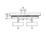
- FIG. 1B shows a cross-sectional view of the gas chromic light control member viewed from the direction of arrow A in FIG. 1A.
- the configurations of the hydrogen supply unit 14 and the dehydrogenation unit 15 are omitted.
- the gaschromic light control member has a pair of transparent base materials 11 as shown in FIG. 1A. And the light control part 12 is arrange
- the first transparent substrate 111 and the second transparent substrate 112 are laminated via the light control unit 12.
- the light control unit 12 is disposed on the surface of the first transparent substrate 111, and the opposing surfaces of the light control unit 12 and the second transparent substrate 112 are in partial contact.
- the pair of transparent base materials 11 can be fixed by the fixing member 13 so that the above-described state can be maintained.
- pipes 16 and 17 connected to openings provided on the surface of the first transparent substrate 111 are provided, and the pipes 16 and 17 have first and first pipes, respectively.
- a hydrogen supply means 14 for supplying a hydrogen-containing gas between the two transparent base materials and a dehydrogenation means 15 for removing hydrogen from between the first and second transparent base materials can be connected.
- FIG. 1B it is described so that there is a gap between the transparent base material 112 and the light control unit 12, but this is described so that the configuration is easy to understand. Can be configured to partially contact. The same applies to FIG.
- the transparent substrate 11 will be described.
- the transparent base material 11 has a first transparent base material 111 and a second transparent base material 112.
- the first transparent base material 111 and the second transparent base material 112 have different thicknesses and sizes, but are not limited to such forms.
- size may be the same and the structure from which any one of thickness and magnitude
- first and second transparent base materials are not limited to the flat plate shape as shown in FIGS. 1A and 1B, as long as both the first and second transparent base materials can be laminated via the light control unit.
- the transparent substrate may have, for example, a curved surface or a spherical surface in the plane, and the shape can be any shape.
- the transparent base material 11 is a member used in a gaschromic light control member, and since it is a member which permeate
- the said transparent base material is glass and / or a plastic, for example.
- the plastic for example, acrylic, polycarbonate, polyethylene terephthalate (PET), polyethylene naphthalate (PEN) and the like can be preferably used.
- the thickness of the transparent substrate is not particularly limited and can be selected from the thickness and strength required for the gaschromic light control member. Any state of thick plates may be used.
- the transparent base material can be provided with an opening for connecting to a hydrogen supply means or the like, if necessary.
- 1A and 1B show a configuration in which two openings are provided so as to be adjacent to one surface, but the present invention is not limited to such a configuration, and openings of any number, shape, and size are provided. be able to.
- piping or the like may be provided on the side surface of the transparent substrate so as to communicate with the transparent substrate. It can also be set as the structure which connected.
- the material and configuration of the light control unit 12 are not particularly limited as long as the light control element 121 included in the light control unit 12 reversibly changes its optical characteristics by hydrogenation / dehydrogenation. Good.
- Two types of materials are known as materials for the light control element 121 whose optical characteristics are reversibly changed by hydrogenation and dehydrogenation. Specifically, a reflective type called a “light control mirror thin film” is known. A dimmer and an absorptive dimmer are known. As the light control element for gas chromic light control of the present embodiment, a reflective light control body and / or an absorption light control body can be used.
- the reflective dimmer can be switched between a transparent state and a mirror state that reflects light by performing hydrogenation and dehydrogenation.
- the absorption dimmer can be switched between a transparent state and a colored state that does not transmit light by performing hydrogenation and dehydrogenation.
- a magnesium alloy thin film can be preferably used as the dimming element of the reflective dimmer, and a transition metal oxide thin film can be preferably used as the dimming element of the absorption dimmer.
- a magnesium alloy thin film and / or a transition metal oxide thin film can be preferably used as the light control element.
- a magnesium alloy thin film can be preferably used as described above, and in particular, a magnesium alloy thin film of magnesium and a transition metal can be more preferably used. Among these, from the viewpoint of durability, a magnesium / nickel alloy thin film or a magnesium / yttrium alloy thin film can be more preferably used.
- a transition metal oxide thin film can be preferably used as described above, and in particular, selected from tungsten oxide, molybdenum oxide, chromium oxide, cobalt oxide, nickel oxide, and titanium oxide.
- a transition metal oxide thin film containing one or more materials can be more preferably used.
- a tungsten oxide thin film can be more preferably used from the viewpoint of coloring efficiency.
- the thickness of the light control element is not particularly limited, and can be selected according to the required degree of light transmission.
- the thickness of one dimmer element is preferably 30 nm or more and 100 nm or less.
- the film thickness of one light control element is 300 nm or more and 800 nm or less.
- the film thickness of one light control element means the thickness of each light control element when it is set as the structure which has a some light control element.
- the method of forming the light control element is not particularly limited, and can be formed by, for example, a sputtering method, a vacuum evaporation method, an electron beam evaporation method, a chemical vapor deposition method, a sol-gel method, and the like. Can be formed on one or both of the opposing surfaces.
- the light control element can be composed of only one layer, but it can also be composed of two or more layers. When two or more layers are laminated, it may be configured to include only one of the reflective dimmer and the absorptive dimmer, or may be configured to include both types of dimmers.
- the light control unit of the present embodiment includes a light control device in which the optical characteristics are reversibly changed by the hydrogenation / dehydrogenation described above, and hydrogenation / dehydrogenation of the light control device.
- a catalyst layer having a catalytic function of the oxidization reaction This is because the reaction rate of the hydrogenation and dehydrogenation reactions of the light control element can be increased by adopting such a configuration.
- a catalyst layer 122 may be formed (laminated) on the surface of the light control element 121 formed on the transparent base 111 that does not face the transparent base 111. preferable.
- the material of the catalyst layer is not particularly limited as long as it can increase the reaction rate of the hydrogenation and dehydrogenation reaction of the light control element.
- it is a thin film of palladium and / or platinum. It is preferable.
- the film thickness of the catalyst layer is not particularly limited and can be arbitrarily selected depending on the cost and the degree of improvement in the required reaction rate, but is preferably 2 nm or more and 10 nm or less.
- the formation method of the catalyst layer is not particularly limited, and can be formed by, for example, a sputtering method, a vacuum evaporation method, an electron beam evaporation method, a chemical vapor deposition method, or the like.
- a buffer layer is provided between the light control element and the catalyst layer to prevent the components of the light control element and the catalyst layer from interdiffusing, and the surface of the catalyst layer. More preferably, a protective film that transmits hydrogen and prevents oxidation of the light control element is provided. By having such a configuration, it is possible to increase the durability of the light control member against repeated switching of hydrogenation and dehydrogenation.
- the buffer layer is not particularly limited as long as the (metal) component of the light control element and the component of the catalyst layer can be prevented from interdiffusion.
- a metal thin film of titanium, niobium, tantalum, or vanadium can be used.
- the method for forming the buffer layer is not particularly limited, and can be formed, for example, by sputtering, vacuum deposition, electron beam deposition, chemical vapor deposition, or the like.
- a layer having hydrogen permeability and water repellency can be preferably used.
- a material having a property of being permeable to hydrogen (proton) and a property of being impermeable to water (water repellency) can be preferably used.
- polymers such as polytetrafluoroethyl, polyvinyl acetate, polyvinyl chloride, polystyrene, and cellulose acetate, and inorganic thin films such as a titanium oxide thin film can be preferably used.
- the protective film can be formed by, for example, a method of applying and drying a dispersion in which a polymer is dispersed, and in the case of an inorganic thin film, for example, by a method of forming an inorganic material by a sputtering method.
- FIG. 1B shows an example in which the light control section 12 is formed on one first transparent base material 111, but is not limited to such a form. For example, it can be formed on the second transparent substrate 112 without being provided on the first transparent substrate 111 side. Moreover, it can also be set as the structure provided in both the 1st and 2nd transparent base materials. Further, FIG. 1B shows a configuration in which the light control element 121 and the catalyst layer 122 are provided as the light control unit 12, but a protective film and a buffer layer may be provided as described above.
- a first dimming element 1211 and a second dimming element 1212 are formed on a first transparent base 111 and a second transparent base 112, respectively, and further, a catalyst layer 1221 is formed on each of them. , 1222 is formed.
- a protective film and a buffer layer can be further provided as described above.
- FIG. 2A the structure is described so that there is a gap between the catalyst layer 1221 and the catalyst layer 1222 so that the structure can be easily understood. .
- the dimmer element has two types of materials (a reflective dimmer and an absorption dimmer).
- the first dimmer 1211 and the second dimmer 1212 are The same type of material may be used, and different types of materials may be used in combination.
- a dimming element of a different type it is preferable to use a dimming element of a different type at the same time because a gaschromic dimming member having a very large optical dynamic range can be realized as compared with the case where only one of them is used.
- a magnesium-yttrium alloy thin film which is a dimming element of a reflective dimmer, is in a mirror state before supplying hydrogen
- a chromium oxide thin film which is a dimming element of an absorbing dimmer, is before supplying hydrogen. Is black and hardly transmits light in this state.
- the magnesium-yttrium alloy thin film changes to a transparent state
- the chromium oxide thin film also changes to a transparent state, and becomes transparent as a whole.
- the optical dynamic range can be increased.
- the color of the magnesium / yttrium alloy thin film and the chromium oxide thin film has been described as an example, but the present invention is not limited to this.
- FIG. 2B shows an example in which the light control unit 12 is formed on the second transparent substrate 112.
- the light control unit 12 is provided on the second transparent substrate 112.
- the example which consists of the light control element 121 and the catalyst layer 122 is shown as a structure of the light control part 12, a protective film and a buffer layer can also be formed as mentioned above.
- 2B shows a form in which the light control member is further bonded to the transparent base material 18 via the adhesive 19.
- the light control member of this embodiment can be further used by affixing to transparent substrates, such as a window glass.
- transparent substrates such as a window glass.
- this is not limited to the case of FIG. 2B, It can be set as the form affixed with transparent base materials, such as a window glass, similarly in the form shown to FIG. 1A, 1B, FIG. 2A.
- the light control member of the present embodiment When the light control member of the present embodiment is used by being attached to a transparent base material 18 in a portion exposed to sunlight such as a window glass, it is included in the sunlight depending on the material of the first transparent base material 111 and the second transparent base material 112.
- the transparent base material may deteriorate due to the influence of ultraviolet rays.
- the dimming element used in the dimming member of the present embodiment either a reflective dimmer or an absorption dimmer can be used.
- the reflectance may vary depending on the surface of the thin film of the element. For example, in FIG. 2B, when the dimming element 121 and the catalyst layer 122 which are reflective dimmers are laminated on the transparent base material 112, the reflectance viewed from the transparent base material 112 side and the catalyst layer 122 side Therefore, the reflectance seen from the transparent substrate 112 side is higher.
- a light control part so that a desired direction may become the target reflectance
- a reflective light control body is used as a light control element, and a mirror is provided on the transparent substrate 18 side.
- the dimmer 12 is arranged as shown in FIG. 2B.
- the fixing member 13 fixes the pair of transparent base materials 11 in which the light control part 12 is formed on one or both of the opposing surfaces as described above.
- the fixing member is not particularly limited as long as it can fix the pair of transparent base materials (111, 112) to each other.
- Various adhesives and tape members as shown in FIGS. 1A and 1B may be used. it can.
- an opening can be formed on the fixing member so as to release hydrogen or the like out of the system.
- it is configured to seal between the transparent base materials except when the opening is intentionally provided as described above so that hydrogen or the like supplied to the light control unit 12 is not intentionally released to the outside. Preferably it is.
- the fixing member 13 fixes the pair of transparent base materials 11, the dimming formed on one of the pair of transparent base materials 11 and the surface of the dimming unit 12 facing each other, or both of the pair of transparent base materials 11. It fixes in the state which the surface which the part 12 opposes partially touches.
- the distance between the facing surfaces is not particularly limited, but it is preferable to fix the surfaces so that the average value is 0.1 mm to 0.2 mm due to the fine uneven shape of the facing surfaces.
- interval of the surface which opposes for example, when a light control part is formed in one surface among the mutually opposing surfaces of a pair of transparent base material, between a light control part and the other transparent base material surface Means the distance. When the light control part is formed in both transparent base materials, the distance between the light control parts is meant.
- the spacer is not disposed between the transparent base materials, and is laminated through the light control unit 12, that is, the light control with one of the pair of transparent base materials 11.
- the volume of the gas filled between them is 5 liters.
- the volume of the gap between the transparent substrates brought into close contact can be reduced to 100 to 200 cc. For this reason, the amount of hydrogen required when hydrogenating the light control member can be reduced.
- the time required for hydrogenation becomes short, it can be set as a gas-chromic light control member with good reactivity.
- a hydrogen-containing gas having a volume of 5 liters is transparent as described above. Due to the presence between the substrates, safety concerns have also been a problem.
- the gas chromic light control member of this embodiment since the volume of the space between the transparent base materials is small, even if the space (gap) is filled with hydrogen and leaks from a part, ignition, etc. There is almost no danger.
- the switching speed can be dramatically increased as compared with the conventional gaschromic light control member.
- the electrical resistance of the transparent conductive film becomes the rate-determining of the switching speed. It took about 10 minutes at the fastest to switch the entire electrochromic light control glass.
- the gaschromic light control member of the present embodiment using the transparent substrate of the same size it is possible to perform switching in a few seconds by introducing hydrogen after reducing the pressure between the transparent substrates. Become. That is, switching can be performed about 100 times faster than the conventional technique.
- the hydrogen supply means 14 is a supply means for supplying a gas containing hydrogen between the pair of transparent base materials 11.
- a hydrogen supply means is not specifically limited, For example, it can be set as the structure which has a replaceable hydrogen cylinder. Further, the hydrogen supply means may be configured to have a hydrogen production means for producing hydrogen. Note that the hydrogen supplied by the hydrogen supply means may be of a concentration that is low enough to hydrogenate the light control member.
- the hydrogen supply unit has a hydrogen production unit.
- the hydrogen production means in this case is not particularly limited, and various hydrogen production means can be applied.
- the hydrogen production means include hydrogen production means by electrolysis of water, hydrogen production means by electrolysis of water contained in air, and hydrogen production by chemical reaction between water and a metal and / or a compound.
- Means, means for producing hydrogen by a chemical reaction between water and metals and / or compounds contained in the air can be used.
- it is not limited to one hydrogen production
- the amount of hydrogen used for switching is small.
- the hydrogen production means uses moisture in the air (a trace amount of moisture contained in the air) as a raw material for hydrogen production.
- hydrogen production means by electrolysis of water contained in the air and hydrogen production means by chemical reaction between moisture and metal and / or compound contained in air can be preferably used.
- Such a configuration is preferable because hydrogen can be produced without adding water.
- the means for producing hydrogen by electrolysis of water is not particularly limited as long as it has a structure capable of electrolyzing water.
- an electrolysis cell using a solid polymer electrolyte membrane can be used.
- hydrogen can be efficiently generated at a voltage of about 3V.
- it may be a means of adding sodium hydroxide or potassium hydroxide to water, putting an electrode, and directly electrolyzing.
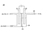
- water in the air is electrolyzed into hydrogen and oxygen using a polymer separation membrane.
- it can be performed by the electrolysis cell 20 shown in FIG.
- an anode 21 and a cathode 22 are disposed, a solid polymer electrolyte membrane 23 is disposed between both electrodes, and water 24 is disposed on the cathode side.
- the hydrogen production means which supplies hydrogen from the hydrogen discharge port 25 by the side of a cathode.
- it is not limited to the form which concerns, It can use similarly if it is a hydrogen production means which electrolyzes the water
- a metal and / or compound that generates hydrogen by reacting with water is reacted with water.
- a metal and / or compound that generates hydrogen by reacting with water is reacted with water.
- examples of such a metal include metal magnesium, and examples of the compound include calcium hydride and magnesium hydride.
- water can also be made into salt water according to reaction, and other components can also be added.
- a configuration as shown in FIG. 4 can be used.
- a tape 31 carrying a metal and / or compound that reacts with water is wound around one reel 321. Then, when generating hydrogen, the other reel 322 is rotated in the direction of the arrow in the drawing to move the water 33 stored in the container when the tape 31 moves, the metal carried on the tape 31, and
- a configuration may be adopted in which the compound is brought into contact with and reacted to be supplied from the hydrogen supply pipe 34 to the outside.
- the hydrogen production means by chemical reaction between water and metal and / or compound, it becomes possible to generate a large amount of hydrogen with almost no use of energy.
- a substance that reacts with moisture in the air and generates hydrogen is placed in a container, And means for generating hydrogen by reacting the water with the substance.
- the substance that reacts with moisture in the air to generate hydrogen include calcium hydroxide.
- Such hydrogen production means is preferable because hydrogen can be supplied without applying energy.
- the metal and / or compound (hereinafter also referred to as “metal etc.”) is used to control the amount of hydrogen released. ) And air are preferably controlled.
- the air supply amount of the air supply means may be controlled.
- the dehydrogenation means 15 is not particularly limited as long as it can remove hydrogen from between the transparent base materials when performing the dehydrogenation of the light control section, and various means can be used. Specifically, for example, first to third configuration examples described below can be used.
- the dehydrogenation means 15 of the first configuration example includes an opening that communicates between the transparent base materials.
- the opening is preferably provided with a valve or the like so that it can be opened and closed.
- hydrogen is naturally diffused from between the transparent substrates to the outside of the system by opening a valve or the like as necessary. Since hydrogen has a high diffusion rate, dehydrogenation can be carried out in a short time even by means that does not use special power.
- the dehydrogenation means 15 preferably has a configuration in which the dehydrogenation means has a gas supply means for supplying a gas between the pair of transparent substrates.
- Such dehydrogenation means forcibly removes the hydrogen-containing gas between the transparent substrates by supplying a gas between the transparent substrates, and dehydrogenates the light control member. According to such means, hydrogen (hydrogen-containing gas) between the transparent substrates can be removed in a shorter time.
- the gas supplied by the gas supply means is not particularly limited as long as it is a gas that can remove hydrogen between a pair of transparent substrates, but is preferably an oxygen-containing gas. This is because dehydrogenation is performed earlier by changing hydrogen to water by oxygen in the oxygen-containing gas.
- the gas supplied by the gas supply means is more preferably air having a reduced oxygen concentration and / or an inert gas containing oxygen.
- the inert gas here may be any gas that does not react with the light control unit, and examples thereof include nitrogen, helium, neon, argon, krypton, and xenon. In particular, nitrogen, argon, and krypton are preferably used. Can do.
- the gas supplied by the gas supply means may be composed of only one type of the above gases, or may be a mixture of a plurality of types of gases selected from the above gases.
- the inventors of the present invention have repeatedly studied the switching mechanism of the gas chromic dimming member, and as described above, the oxygen-containing gas can be preferably used as the gas supplied by the gas supply means of the present embodiment. It has been found that an oxygen-containing gas with a controlled oxygen concentration can be used particularly preferably. This point will be described.
- the light control device of the gas chromic light control member of this embodiment reversibly changes the optical characteristics by performing hydrogenation and dehydrogenation reactions.
- dehydrogenation can be performed by reducing the hydrogen concentration around the light control element, that is, in the gap between the transparent base materials. For this reason, dehydrogenation can be performed by lowering the hydrogen concentration by supplying gas to the gap between the transparent substrates by the gas supply means.
- oxygen was introduced into the gas supplied by the gas supply means, this oxygen extracted hydrogen as water, so that dehydrogenation could be performed at a higher rate. Is.
- oxygen having an appropriate concentration as the gas supplied between the transparent substrates during dehydrogenation. That is, it is preferable to use a gas containing oxygen at a concentration that does not cause condensation between the transparent substrates. That is, the oxygen concentration of the oxygen-containing gas supplied by the gas supply means is such that the amount of water (water vapor pressure) generated between the pair of transparent substrates by introducing the oxygen-containing gas does not exceed the saturated vapor pressure. Preferably there is. Moreover, it is preferable to have a water removal means that can be removed from between the transparent substrates at an early stage when water is generated.
- Such gas supply means for supplying a gas can be constituted by a cylinder storing a predetermined gas.
- it can be constituted by a cylinder storing the oxygen-containing gas as described above.
- the dehydrogenation means has an oxygen reduction means for reducing oxygen and / or a first moisture removal means for removing moisture from the gas supplied between the pair of transparent substrates by the gas supply means. You can also By adopting such a configuration, for example, by allowing air to pass through the oxygen reducing unit and / or the first moisture removing unit, it is possible to produce a gas that hardly causes dew condensation between the transparent substrates. Become.
- examples of the oxygen reducing means include an oxygen scavenger and a nitrogen separator
- examples of the first moisture removing means include a moisture removing film and a desiccant.
- the gas is supplied between the transparent base materials by the gas supply means, so that the supplied gas is discharged to the outside from between the transparent base materials.
- the gas supply means As a means for releasing gas to the outside from between the transparent base materials, for example, it is configured to diffuse naturally outside the system from an opening not shown in FIGS. 1A and 1B provided in communication between the transparent base materials. Can do.
- it can also be set as the structure which connects a pump etc. to the said opening part, and exhausts it forcibly.
- the opening may be provided in a part of the fixing member 13 for laminating and fixing a pair of transparent substrates. Moreover, it can also be set as the structure which provided the opening part which is not shown in figure in a transparent base material.
- the opening can be always open, but in this case, it is necessary to supply extra hydrogen when the dimming member is hydrogenated. It is preferable to do.
- the dehydrogenation means when the gas supply means supplies an oxygen-containing gas, the dehydrogenation means further includes a hydrogen exhaust means or a pair of hydrogen exhausting hydrogen from between a pair of transparent substrates. It is preferable that a pressure reducing means for reducing the pressure between the transparent substrates is provided. Then, after reducing the hydrogen partial pressure between the pair of transparent base materials by the hydrogen exhausting means or the pressure reducing means, the oxygen supply gas is introduced between the pair of transparent base materials by the gas supply means to dehydrogenate the light control element. It is preferable to carry out.
- the oxygen concentration of the oxygen-containing gas is such that the amount of water generated between the pair of transparent substrates by introducing the oxygen-containing gas does not exceed the saturated water vapor pressure.
- the hydrogen exhausting means or the pressure reducing means is not particularly limited as long as it is a means capable of exhausting hydrogen from between the transparent base materials or reducing the pressure between the transparent base materials, but the third configuration example of the dehydrogenating means.
- the hydrogen evacuation means and the decompression means described later can be preferably used.
- the gas supply means collects and circulates the gas supplied between the pair of transparent base materials, and the gas supply means
- the oxygen reduction means and / or the first moisture removal means may be provided on a path for supplying the recovered gas again between the pair of transparent substrates. That is, it can be configured such that the gas released between the transparent substrates (extruded) is collected and recycled while supplying the gas between the transparent substrates by the gas supply means.
- FIGS. 5A and 5B can be adopted.
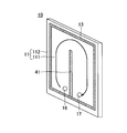
- FIG. 5A shows a perspective view of the gas chromic light control member as in FIG. 1A
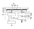
- FIG. 5B shows a cross-sectional view as seen from the upper surface side like FIG. 1B.
- the description about the hydrogen supply means 14 and the dehydrogenation means 15 is omitted.
- the description of the configuration described with reference to FIGS. 1A and 1B is omitted here.
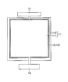
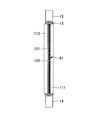
- the dehydrogenation means 15 can be configured to include, for example, a pump 151 as a gas supply means. And gas is circulated by the pump 151 in the direction shown by the arrow in the figure to expel the gas containing hydrogen between the transparent substrates.
- the oxygen-containing gas can be preferably used as the gas circulated and supplied by the pump 151 serving as the gas supply means as described above.
- oxygen reducing means and / or first moisture removing means 154 on the path as shown in FIG. 5B.
- oxygen reducing means an oxygen separation membrane or an oxygen adsorbing material can be used.
- first moisture removing means a moisture removing film or a desiccant can be used.
- the hydrogen separation means 152 is not particularly limited, and examples thereof include a means using a hydrogen separation membrane, a nitrogen separator, and a hydrogen storage material.
- the hydrogen separation means using a hydrogen separation membrane is provided with a known hydrogen separation membrane, and only hydrogen is separated from the circulated gas and released out of the system.
- a hydrogen separation means using a nitrogen separator it can be preferably used when the circulating gas is air or a gas containing nitrogen as a main component.
- the nitrogen separator is composed of a polymer fiber or the like, and oxygen, hydrogen, and water having a molecular size smaller than that of nitrogen are removed when passing through the separator and are released out of the system. For this reason, not only hydrogen but also oxygen and water can be removed from the circulated gas, which can be particularly preferably used.
- the circulating gas is brought into contact with the hydrogen storage material.
- the hydrogen stored in the hydrogen storage material can also be used when the light control member is hydrogenated.
- the piping 155 can be configured to connect a cylinder filled with a gas used for circulation and replenish the circulating gas.
- the dehydrogenation means 15 includes the oxygen reduction means 154 as described above, or when a nitrogen separator is used as the hydrogen separation means 152, the air is circulated even if it is supplied as it is. In addition, the oxygen concentration can be reduced. For this reason, in this case, it is possible to adopt a configuration in which means for supplying air is connected to the circulation gas replenishment pipe 155. Thus, it is preferable to be able to circulate a stable amount of gas by configuring so that the circulating gas can be replenished.
- the hydrogen supply means 14 is connected to the pump 151 as shown in FIG. 5B, and when hydrogenation is performed, the hydrogen from the hydrogen supply means 14 is used. Can be mixed with the circulating gas and supplied between the transparent substrates by a pump 151.
- the hydrogen supply means 14 can also be configured to separately form an opening communicating with the transparent base material and to connect to the transparent base material to supply hydrogen between the transparent base materials.
- a transparent base is formed by using one transparent substrate and a light control member formed on the surface of the other transparent substrate so that gas can be circulated and supplied uniformly between the transparent substrates.
- an adhesive member 41 that adheres except for a part at the center in the width direction of the material. By comprising in this way, when supplying gas from the piping 16 connected to the opening part, for example, it circulates between transparent base materials according to the arrow in the figure, and from between the transparent base materials in the piping 17 connected to the opening part. It is preferable that the gas is discharged.
- the adhesive member 41 is not limited to the case where the dehydrogenation means is in this configuration example, and can be provided in the case of another configuration example.
- an adhesive member will be provided between the uppermost layers of a light control member as mentioned above.
- the form of the adhesive member 41 is not limited to the form of FIGS. 5A and 5B, and is formed in an arbitrary shape so that the gas supplied from one opening is uniformly supplied between the transparent base materials. can do.
- the dehydrogenation means is further provided between the pair of transparent substrates.
- a hydrogen exhaust means for exhausting hydrogen or a pressure reducing means for reducing the pressure between the pair of transparent substrates is provided. Then, after reducing the hydrogen partial pressure between the pair of transparent base materials by the hydrogen exhausting means or the pressure reducing means, the oxygen supply gas is introduced between the pair of transparent base materials by the gas supply means to dehydrogenate the light control element. It is preferable to carry out.
- the oxygen concentration of the oxygen-containing gas is such that the amount of water generated between the pair of transparent substrates by introducing the oxygen-containing gas does not exceed the saturated water vapor pressure.
- Such a configuration can suppress the generation of water between the transparent substrates.
- the hydrogen exhausting means or the pressure reducing means is not particularly limited as long as it is a means capable of exhausting hydrogen from between the transparent base materials or reducing the pressure between the transparent base materials, but the third configuration example of the dehydrogenating means.
- the hydrogen evacuation means and the decompression means described later can be preferably used.
- valves 16 and 17 are provided with valves so that they can be opened and closed.
- the dehydrogenation means includes a hydrogen exhaust means for exhausting hydrogen between the pair of transparent substrates or a decompression means for reducing the pressure between the pair of transparent substrates.
- Such hydrogen evacuation means or pressure reduction means is for sucking and evacuating hydrogen from between transparent substrates, and further reducing the pressure in some cases.
- a pump vacuum pump
- a fuel cell a hydrogen adsorbent and / or Hydrogen storage materials
- Dehydrogenation is performed by removing hydrogen from between the transparent substrates by such means.
- the pump suction port can be connected to the pipe 17 connected to the opening provided in the transparent substrate as described above.
- the type of the pump is not particularly limited as long as hydrogen can be exhausted from between the transparent substrates or the pressure between the transparent substrates can be reduced.
- a rotary pump or a diaphragm pump can be preferably used.
- a pair of transparent base materials are stacked via the light control unit, and the transparent base material and the light control unit (or the light control unit) Have a structure in which they are in direct contact with each other. For this reason, there is no need to reinforce the strength by arranging pillars or the like in order to create a vacuum between the transparent substrates.
- a configuration using a fuel cell as a hydrogen exhaust means will be described.
- a fuel cell may be configured to connect the hydrogen electrode side of the fuel cell and the pipe 17 connected to the opening.
- the hydrogen electrode side of the fuel cell consumes hydrogen when generating power, so that hydrogen between the transparent substrates can be sucked and removed.
- air may be supplied to the oxygen electrode side of the fuel cell.
- the electricity generated by the fuel cell can be configured to be used in various incidental facilities of the gas chromic dimming member.
- the container in which the hydrogen adsorbent and / or the hydrogen storage material is installed can be connected to the pipe 17 connected to the opening via a valve.
- the valve When removing hydrogen between the transparent substrates, the valve can be opened, and the hydrogen can be sucked and removed by adsorbing and storing hydrogen in the hydrogen adsorbent and / or hydrogen storage material.
- the hydrogen adsorbed and stored in the hydrogen adsorbent and / or the hydrogen storage material can be released and utilized when the light control member is hydrogenated.
- the hydrogen exhausting means and the pressure reducing means are given, but the present invention is not limited to these, and various means can be used as long as hydrogen can be sucked, exhausted, and reduced in pressure from the transparent substrate. Can do. Further, not only one means but also a plurality of means can be used in combination.
- gas chromic light control member of this embodiment was demonstrated, various incidental facilities can be installed.
- the pressure reducing means reducing the oxygen partial pressure and the water vapor partial pressure
- water is supplied when hydrogen is supplied.
- production can be suppressed and it can make it hard to form condensation even when water generate
- hydrogenation reaction can be advanced more quickly.
- the dehydrogenation unit includes a decompression unit that depressurizes between the pair of transparent substrates.
- the pressure reduction means can also be used in the hydrogenation treatment as described above.
- it can also be set as the structure which has a pressure reduction means further in addition to the pressure reduction means of the dehydrogenation means which concerns.
- the structure further equipped with the oxygen removal means to remove the oxygen between a pair of transparent base materials, and / or the 2nd moisture removal means to remove the water
- Such oxygen removing means and / or second moisture removing means can be provided so as to communicate directly between the pair of transparent substrates. By providing these members, the oxygen partial pressure and the water vapor partial pressure between the transparent substrates can be kept low, so that deterioration of the light control element can be suppressed.
- the oxygen and / or the second moisture removing unit removes oxygen and / or the pair of transparent substrates.
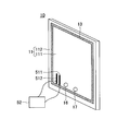
- the hydrogen concentration detection means can be set as the structure provided with the hydrogen concentration detection means between a pair of transparent base materials.
- the hydrogen concentration detection means a conventionally known hydrogen concentration detection sensor may be used, but the electric resistance value of the dimming element of the present embodiment varies depending on the surrounding hydrogen concentration. For this reason, it can be set as the structure which detects hydrogen concentration by measuring the electrical resistance of a light control element as a hydrogen concentration detection means using such a characteristic.
- electrodes 511 and 512 connected to the electrical resistance measuring device 52 and electrical resistance measuring means 52 connected to the electrodes are provided on the surface of the light control member, particularly the light control element. It can be set as the structure which detects the hydrogen concentration between transparent base materials from the electrical resistance value measured with the resistance measurement means 52.
- the hydrogen concentration detection means that can detect the hydrogen concentration between the transparent base materials 11 only by measuring the electric resistance, the hydrogen concentration between the transparent base materials can be easily detected at low cost. Become.
- Detecting the hydrogen concentration between the transparent base materials 11 makes it possible to easily control the hydrogen supply means 14 and the dehydrogenation means 15 during hydrogenation and dehydrogenation. Further, since the state (transparency) of the optical property of the light control member can be confirmed from the hydrogen concentration, it is possible to control the supply and removal of hydrogen so that the set optical property state is obtained. Furthermore, it is possible to configure so as to issue an alarm when the hydrogen concentration changes abnormally.
- a hydrogen concentration reducing means for reducing the concentration of hydrogen from the gas released to the outside is provided on the path for releasing the hydrogen-containing gas to the outside.
- Such hydrogen concentration reducing means is preferably means having palladium and / or a hydrogen storage material.
- palladium When palladium is used as a means for reducing the hydrogen concentration, hydrogen introduced into the exhaust pipe by the catalytic action of palladium and oxygen in the air react to turn into water, and only water and air are released out of the system. It will be.
- a palladium thin film for palladium for example, it is preferable to use what formed the palladium thin film on the support
- the hydrogen storage material when a hydrogen storage material is used as a means for reducing the hydrogen concentration, the hydrogen storage material can absorb and release hydrogen, so it is possible to store hydrogen and suppress the release of hydrogen outside the system. become.
- the hydrogen storage material can be composed of a light control thin film that forms a light control element used in the light control member. In this case, in order to increase the chance of contact with hydrogen, it is preferable to use a light control thin film formed on a carrier.
- various hydrogen storage materials such as Mg and LaNi 5 can be used.
- the apparatus can be miniaturized and the degree of freedom in shape is higher than that of the conventional light control member.
- the gas chromic light control member of this embodiment is an automatic light control member and has a configuration shown in FIGS. 7A and 7B.
- FIG. 7A has a pair of transparent base materials 11 (111, 112) as described in the first embodiment.
- the light control part is arrange
- the base material 111 and the second transparent base material 112 are laminated and fixed by the fixing member 13.
- the hydrogen supply means 14 is provided in the lower part, and as the dehydrogenation means 15, an opening part is provided in a part of the fixing member 13, and hydrogen is supplied. It is configured to be discharged out of the device by natural diffusion.
- the hydrogen production means is a shape-deformable container containing moisture, metal, and / or compound contained in the air, such as a bag, and has a shape memory at its entrance.
- the alloy 72 is arranged. Since the shape memory alloy 72 changes its shape according to the outside air temperature, the mouth of the container opens when the outside air temperature becomes high, and air easily enters the container. For this reason, when the outside air temperature increases, the amount of hydrogen generated increases.
- the generated hydrogen is supplied between the transparent base materials 11, and the light control unit (light control element) changes the optical characteristics.
- an automatic light control member that blocks sunlight can be obtained only when the temperature is high.
- the image display device provided with the gas chromic light control member of the present embodiment includes the gas chromic light control member 10 described in the first embodiment on the front surface of the image display device 81 as shown in FIG. 8, for example. It is.
- the transparent base material is not provided with an opening, and a pipe communicating between the transparent base materials 11 is fixed by a fixing member 13 as shown in FIG. 8, and the pipe, the hydrogen supply means 14 and the dehydrogenation are fixed. It is preferable from the viewpoint of visibility that the device 15 is configured to be connected.
- the light control part (the light control element 121, the catalyst layer 122) provided in the gas chromic light control member has a reflection type light control element.
- the mirror is normally used as a mirror, and if necessary, the dimmer can be made transparent to view the image on the image display device. It can be preferably used in a beauty salon or the like.
- the gas chromic light control member described in the first embodiment will be described.
- An anti-glare mirror is a mirror that changes from a mirror state to a low-reflection state so as not to be dazzled when illuminated with a headlight from behind at night, as used mainly in a car room mirror.
- Fig. 9 shows a specific example of the structure.
- the gaschromic light control member described in the first embodiment has a configuration in which a mirror surface 91 is provided on one surface of one transparent substrate 111.
- the light control element of the gas chromic light control unit is preferably an absorption type light control body, and specifically, for example, a tungsten oxide thin film.
Landscapes
- Engineering & Computer Science (AREA)
- Structural Engineering (AREA)
- Civil Engineering (AREA)
- Architecture (AREA)
- Physics & Mathematics (AREA)
- Nonlinear Science (AREA)
- Electrochromic Elements, Electrophoresis, Or Variable Reflection Or Absorption Elements (AREA)
- General Physics & Mathematics (AREA)
- Optics & Photonics (AREA)
Abstract
Description
1)電流・電圧の印加により可逆的に光透過率の変化するエレクトロクロミック材料
2)温度により光透過率が変化するサーモクロミック材料
3)雰囲気ガスの制御により光透過率が変化するガスクロミック材料
この中でも、調光素子として酸化タングステン薄膜等のエレクトロクロミック材料を用いたエレクトロクロミック調光部材の研究が最も進んでおり、現在、ほぼ実用化段階に達しており、市販品も出されている。しかしながら、エレクトロクロミック調光部材は十分な光学特性を得るためには調光部材を構成する調光素子を5層程度の多層薄膜構造にする必要があり、コストが非常に高くなってしまうという問題がある。これに対して、ガスクロミック調光部材は調光素子の構造がエレクトロクロミック調光部材に比べて簡単なので、低コストで製造できる調光部材として期待されており、その調光素子の材料や調光部の構造について各種検討がなされてきた(例えば、特許文献1~4)。
[第1の実施形態]
本実施形態では、本発明のガスクロミック調光部材の構成例について説明する。
[第2の実施形態]
本実施形態では、第1の実施形態で説明したガスクロミック調光部材の応用構成例について説明する。
[第3の実施形態]
本実施形態では、第1の実施形態で説明したガスクロミック調光部材の応用構成例について説明する。
[第4の実施形態]
本実施形態では、第1の実施形態で説明したガスクロミック調光部材の応用構成例について説明する。
12(121、122) 調光部
121 調光素子
122 触媒層
14 水素供給手段
15 脱水素化手段
Claims (19)
- 第1の面を有する第1の透明部材と、
第2の面を有し、該第2の面が前記第1の透明部材の第1の面に対向するように配置された第2の透明部材と、
前記第1の面に形成され、水素化・脱水素化により光学的特性が可逆的に変化する調光素子を有する調光部と、
前記第1及び第2の透明基材間に水素含有気体を導入する水素供給手段と、
前記第1及び第2の透明基材間から水素を除去する脱水素化手段と、を備え、
前記第1及び第2の透明基材は前記調光部を介して積層され、前記第2の面と前記第2の面に対向する前記調光部の面が部分的に接しているガスクロミック調光部材。 - 前記脱水素化手段が、前記第1及び第2の透明基材間に気体を供給する気体供給手段を有する請求項1に記載のガスクロミック調光部材。
- 前記脱水素化手段は、
前記気体供給手段により前記第1及び第2の透明基材間に供給する気体中から、酸素を低減する酸素低減手段及び水分を除去する第1の水分除去手段の少なくともいずれか一方を有する請求項2に記載のガスクロミック調光部材。 - 前記気体供給手段は前記第1及び第2の透明基材間に供給した気体を回収し、循環使用しており、
前記気体供給手段は、回収した気体を前記第1及び第2の透明基材間に再度供給するための経路上に、前記酸素低減手段及び前記第1の水分除去手段の少なくともいずれか一方を備えている請求項3に記載のガスクロミック調光部材 - 前記気体供給手段が供給する気体が、酸素含有気体である請求項2に記載のガスクロミック調光部材。
- 前記脱水素化手段が、前記第1及び第2の透明基材間から水素を排気する水素排気手段及び前記第1及び第2の透明基材間を減圧する減圧手段のいずれか一方を備えており、
前記水素排気手段または減圧手段により、前記第1及び第2の透明基材間の水素分圧を低下した後、
前記気体供給手段により前記第1及び第2の透明基材間に酸素含有気体を導入することにより前記調光素子の脱水素化を行い、
前記酸素含有気体の酸素濃度が、前記酸素含有気体を導入することにより前記第1及び第2の透明基材間に発生する水の量が飽和水蒸気圧を超えない濃度である請求項5に記載のガスクロミック調光部材。 - 前記脱水素化手段が、前記第1及び第2の透明基材間から水素を排気する水素排気手段または前記第1及び第2の透明基材間を減圧する減圧手段を備えている請求項1に記載のガスクロミック調光部材。
- 前記第1及び第2の透明基材間を減圧する減圧手段をさらに備えている請求項1に記載のガスクロミック調光部材。
- 前記第1及び第2の透明基材間の酸素を除去する酸素除去手段及び前記第1及び第2の透明基材間の水分を除去する第2の水分除去手段の少なくともいずれか一方をさらに備えている請求項1に記載のガスクロミック調光部材。
- 前記水素供給手段が、前記第1及び第2の透明基材間に水素を供給する前に、前記酸素除去手段及び前記第2の水分除去手段の少なくともいずれか一方により、前記第1及び第2の透明基材間の酸素及び水分の少なくともいずれか一方を除去する請求項9に記載のガスクロミック調光部材。
- 前記透明基材が、ガラスまたはプラスチックである請求項1に記載のガスクロミック調光部材。
- 前記調光部が、前記調光素子の水素化・脱水素化反応の触媒機能を有する触媒層をさらに備えている請求項1に記載のガスクロミック調光層。
- 前記調光素子と前記触媒層との間には、前記調光素子の成分と前記触媒層の成分とが相互拡散することを防止するためのバッファー層が設けられ、
前記触媒層の表面には、水素を透過し前記調光素子の酸化を防止する保護膜が設けられている請求項12に記載のガスクロミック調光部材。 - 前記調光素子として、マグネシウム合金薄膜および遷移金属酸化物薄膜の少なくともいずれか一方を、
前記触媒層として、パラジウムおよび白金の少なくともいずれか一方を含む薄膜を、それぞれ有する請求項12に記載のガスクロミック調光部材。 - 前記水素供給手段は水素を製造するための水素製造手段を有する請求項1に記載のガスクロミック調光部材。
- 前記水素製造手段は、水素製造の際の原料として、空気中の水分を用いることを特徴とする請求項15に記載のガスクロミック調光部材。
- 水素含有気体を外部に放出する経路上に、外部に放出する気体から水素の濃度を低減する水素濃度低減手段を備えており、
前記水素濃度低減手段は、パラジウムおよび水素貯蔵材料の少なくともいずれか一方を有する手段である請求項1に記載のガスクロミック調光部材。 - 前記第1及び第2の透明基材間の水素濃度検出手段を備えており、
前記水素濃度検出手段は、前記調光素子の電気抵抗を測定することにより水素濃度を検出する、請求項1に記載のガスクロミック調光部材。 - 第1の面を有する第1の透明部材と、
第2の面を有し、該第2の面が前記第1の透明部材の第1の面に対向するように配置された第2の透明部材と、
前記第1の面に形成され、水素化・脱水素化により光学的特性が可逆的に変化する調光素子を有する第1の調光部と、
前記第2の面に形成され、水素化・脱水素化により光学的特性が可逆的に変化する調光素子を有する第2の調光部と、
前記第1及び第2の透明基材間に水素含有気体を導入する水素供給手段と、
前記第1及び第2の透明基材間から水素を除去する脱水素化手段と、を備え、
前記第1及び第2の透明基材は前記第1及び第2の調光部を介して積層され、前記第1の調光部と前記第2の調光部の対向する面が部分的に接しているガスクロミック調光部材。
Priority Applications (3)
| Application Number | Priority Date | Filing Date | Title |
|---|---|---|---|
| KR1020157018167A KR101685584B1 (ko) | 2013-01-10 | 2013-12-16 | 가스크로믹 조광 부재 |
| US14/758,986 US9376854B2 (en) | 2013-01-10 | 2013-12-16 | Gasochromic system |
| CN201380069803.6A CN104995555B (zh) | 2013-01-10 | 2013-12-16 | 气致变色调光部件 |
Applications Claiming Priority (2)
| Application Number | Priority Date | Filing Date | Title |
|---|---|---|---|
| JP2013002675A JP6112601B2 (ja) | 2013-01-10 | 2013-01-10 | ガスクロミック調光部材。 |
| JP2013-002675 | 2013-01-10 |
Publications (1)
| Publication Number | Publication Date |
|---|---|
| WO2014109182A1 true WO2014109182A1 (ja) | 2014-07-17 |
Family
ID=51166842
Family Applications (1)
| Application Number | Title | Priority Date | Filing Date |
|---|---|---|---|
| PCT/JP2013/083681 Ceased WO2014109182A1 (ja) | 2013-01-10 | 2013-12-16 | ガスクロミック調光部材 |
Country Status (5)
| Country | Link |
|---|---|
| US (1) | US9376854B2 (ja) |
| JP (1) | JP6112601B2 (ja) |
| KR (1) | KR101685584B1 (ja) |
| CN (1) | CN104995555B (ja) |
| WO (1) | WO2014109182A1 (ja) |
Cited By (2)
| Publication number | Priority date | Publication date | Assignee | Title |
|---|---|---|---|---|
| CN107111202A (zh) * | 2014-12-26 | 2017-08-29 | 国立研究开发法人产业技术综合研究所 | 气致变色调光机构 |
| CN107615157A (zh) * | 2015-05-21 | 2018-01-19 | 日东电工株式会社 | 调光薄膜及其制造方法、以及调光元件 |
Families Citing this family (10)
| Publication number | Priority date | Publication date | Assignee | Title |
|---|---|---|---|---|
| JP6204206B2 (ja) | 2014-01-22 | 2017-09-27 | 株式会社アツミテック | 自立型調光システム |
| KR102320737B1 (ko) * | 2015-01-14 | 2021-11-03 | 삼성디스플레이 주식회사 | 헤드-장착 전자장치 |
| WO2017164285A1 (ja) * | 2016-03-25 | 2017-09-28 | 日東電工株式会社 | 調光フィルムの製造方法 |
| WO2017188410A1 (ja) * | 2016-04-28 | 2017-11-02 | 国立研究開発法人産業技術総合研究所 | ガスクロミック調光素子及びその製造方法、ガスクロミック調光部材並びに複層ガラス |
| CN108085645A (zh) * | 2016-11-21 | 2018-05-29 | 中国科学院上海硅酸盐研究所 | 一种镁钇合金全反射型调光薄膜及其制备方法和应用 |
| CN107591485B (zh) * | 2017-08-03 | 2020-03-24 | 华南农业大学 | 一种可动态调控透明度的有机太阳能电池及其制备方法和应用 |
| US20200401010A1 (en) | 2018-03-16 | 2020-12-24 | Nitto Denko Corporation | Gaschromic light control element |
| US11782261B2 (en) | 2018-10-01 | 2023-10-10 | Centre For Nano And Soft Matter Sciences | Visibility controlling device |
| WO2020158799A1 (ja) * | 2019-01-30 | 2020-08-06 | 日東電工株式会社 | 調光フィルムおよびその製造方法 |
| CN115268159A (zh) * | 2022-09-13 | 2022-11-01 | 义乌清越光电技术研究院有限公司 | 电致变色调控光栅和显示面板 |
Citations (3)
| Publication number | Priority date | Publication date | Assignee | Title |
|---|---|---|---|---|
| JP2003261356A (ja) * | 2002-03-11 | 2003-09-16 | National Institute Of Advanced Industrial & Technology | マグネシウム薄膜を用いた調光ミラーガラス |
| JP2009544997A (ja) * | 2006-07-28 | 2009-12-17 | サン−ゴバン グラス フランス | 可変エネルギー/光伝送特性を有する能動素子 |
| JP2010078890A (ja) * | 2008-09-25 | 2010-04-08 | National Institute Of Advanced Industrial Science & Technology | マグネシウム・ジルコニウム合金薄膜を用いた反射型調光薄膜材料及び反射型調光部材 |
Family Cites Families (12)
| Publication number | Priority date | Publication date | Assignee | Title |
|---|---|---|---|---|
| WO1996038758A1 (en) | 1995-05-30 | 1996-12-05 | Philips Electronics N.V. | Switching device and the use thereof |
| EP0871926B1 (en) | 1996-09-05 | 2004-02-11 | Koninklijke Philips Electronics N.V. | Optical switching device |
| US6647166B2 (en) | 2000-08-17 | 2003-11-11 | The Regents Of The University Of California | Electrochromic materials, devices and process of making |
| WO2002042831A2 (en) * | 2000-11-27 | 2002-05-30 | Koninklijke Philips Electronics N.V. | Electrochromic optical switching device |
| US6762871B2 (en) * | 2002-03-11 | 2004-07-13 | National Institute Of Advanced Industrial Science And Technology | Switchable mirror glass using magnesium-containing thin film |
| US7433560B2 (en) * | 2005-10-18 | 2008-10-07 | Lucent Technologies Inc. | Rectangular-passband multiplexer |
| US7894117B2 (en) * | 2006-01-13 | 2011-02-22 | Andrew Finlayson | Transparent window switchable rear vision mirror |
| JP4193185B2 (ja) * | 2006-07-12 | 2008-12-10 | 独立行政法人産業技術総合研究所 | 無色透明にできる反射型調光薄膜材料 |
| JP4789090B2 (ja) * | 2006-07-12 | 2011-10-05 | 独立行政法人産業技術総合研究所 | マグネシウム・ニオブ合金薄膜を用いた反射型調光薄膜材料 |
| JP5166347B2 (ja) * | 2008-08-12 | 2013-03-21 | 独立行政法人産業技術総合研究所 | 反射型調光素子、並びに、反射型調光素子を用いた反射型調光部材及び複層ガラス |
| CN101510014A (zh) * | 2009-03-18 | 2009-08-19 | 电子科技大学 | 一种气致变色器件及其制备方法 |
| CN107111202B (zh) * | 2014-12-26 | 2020-05-26 | 国立研究开发法人产业技术综合研究所 | 气致变色调光机构 |
-
2013
- 2013-01-10 JP JP2013002675A patent/JP6112601B2/ja not_active Expired - Fee Related
- 2013-12-16 CN CN201380069803.6A patent/CN104995555B/zh not_active Expired - Fee Related
- 2013-12-16 KR KR1020157018167A patent/KR101685584B1/ko not_active Expired - Fee Related
- 2013-12-16 US US14/758,986 patent/US9376854B2/en not_active Expired - Fee Related
- 2013-12-16 WO PCT/JP2013/083681 patent/WO2014109182A1/ja not_active Ceased
Patent Citations (3)
| Publication number | Priority date | Publication date | Assignee | Title |
|---|---|---|---|---|
| JP2003261356A (ja) * | 2002-03-11 | 2003-09-16 | National Institute Of Advanced Industrial & Technology | マグネシウム薄膜を用いた調光ミラーガラス |
| JP2009544997A (ja) * | 2006-07-28 | 2009-12-17 | サン−ゴバン グラス フランス | 可変エネルギー/光伝送特性を有する能動素子 |
| JP2010078890A (ja) * | 2008-09-25 | 2010-04-08 | National Institute Of Advanced Industrial Science & Technology | マグネシウム・ジルコニウム合金薄膜を用いた反射型調光薄膜材料及び反射型調光部材 |
Cited By (4)
| Publication number | Priority date | Publication date | Assignee | Title |
|---|---|---|---|---|
| CN107111202A (zh) * | 2014-12-26 | 2017-08-29 | 国立研究开发法人产业技术综合研究所 | 气致变色调光机构 |
| CN107111202B (zh) * | 2014-12-26 | 2020-05-26 | 国立研究开发法人产业技术综合研究所 | 气致变色调光机构 |
| CN107615157A (zh) * | 2015-05-21 | 2018-01-19 | 日东电工株式会社 | 调光薄膜及其制造方法、以及调光元件 |
| CN107615157B (zh) * | 2015-05-21 | 2021-01-08 | 日东电工株式会社 | 调光薄膜及其制造方法、以及调光元件 |
Also Published As
| Publication number | Publication date |
|---|---|
| JP6112601B2 (ja) | 2017-04-12 |
| CN104995555A (zh) | 2015-10-21 |
| US9376854B2 (en) | 2016-06-28 |
| KR101685584B1 (ko) | 2016-12-12 |
| JP2014134676A (ja) | 2014-07-24 |
| CN104995555B (zh) | 2018-04-13 |
| US20150354265A1 (en) | 2015-12-10 |
| KR20150092299A (ko) | 2015-08-12 |
Similar Documents
| Publication | Publication Date | Title |
|---|---|---|
| JP6112601B2 (ja) | ガスクロミック調光部材。 | |
| CN104412154B (zh) | 反射型调光元件 | |
| US8773746B2 (en) | All-solid-state reflective dimming electrochromic element sealed with protective layer, and dimming member comprising the same | |
| JP5136978B2 (ja) | バッファ層を有する全固体型反射調光エレクトロクロミック素子及びそれを用いた調光部材 | |
| KR101724782B1 (ko) | 수소흡장 합금 및 이것을 사용한 수소센서 | |
| US6259549B1 (en) | Laminated glass pane assembly with electrically controllable reflectance and method of making said assemblies | |
| US10247997B2 (en) | Switchable hydride smart window and the methods for producing the same | |
| EP2762968A1 (en) | Reflective dimming element, reflective dimming member and multi-layered glass | |
| WO2008075695A1 (ja) | マグネシウム・チタン合金を用いた全固体型反射調光エレクトロクロミック素子及び調光部材 | |
| CN103797411A (zh) | 嵌入有非水系氢离子导电性电解质层的反射型调光电致变色元件以及使用了它的调光构件 | |
| JP2010066747A (ja) | 反射型調光素子、並びに、反射型調光素子を用いた反射型調光部材及び複層ガラス | |
| CA2456111C (en) | System comprising a glazing element and a gas supply device | |
| CN107615157A (zh) | 调光薄膜及其制造方法、以及调光元件 | |
| JP6332820B2 (ja) | ガスクロミック調光機構 | |
| US5652433A (en) | Bistable switching device containing gadolinium hydride | |
| JP2005351933A (ja) | 反射調光エレクトロクロミック素子、当該素子の製造方法、および当該素子を用いた反射調光ガラス | |
| JP4984064B2 (ja) | 光反射透過材料、光反射透過装置および光反射透過窓 | |
| Yoshimura | Metal Hydrides for Smart‐Window Applications | |
| JP4930990B2 (ja) | マグネシウム・ニオブ合金を用いた全固体型反射調光エレクトロクロミック素子及び調光部材 |
Legal Events
| Date | Code | Title | Description |
|---|---|---|---|
| 121 | Ep: the epo has been informed by wipo that ep was designated in this application |
Ref document number: 13870614 Country of ref document: EP Kind code of ref document: A1 |
|
| WWE | Wipo information: entry into national phase |
Ref document number: 14758986 Country of ref document: US |
|
| ENP | Entry into the national phase |
Ref document number: 20157018167 Country of ref document: KR Kind code of ref document: A |
|
| NENP | Non-entry into the national phase |
Ref country code: DE |
|
| 122 | Ep: pct application non-entry in european phase |
Ref document number: 13870614 Country of ref document: EP Kind code of ref document: A1 |