WO2014104277A1 - Appareil de commande, système de communication, procédé de commande de nœud de communication et programme - Google Patents
Appareil de commande, système de communication, procédé de commande de nœud de communication et programme Download PDFInfo
- Publication number
- WO2014104277A1 WO2014104277A1 PCT/JP2013/085050 JP2013085050W WO2014104277A1 WO 2014104277 A1 WO2014104277 A1 WO 2014104277A1 JP 2013085050 W JP2013085050 W JP 2013085050W WO 2014104277 A1 WO2014104277 A1 WO 2014104277A1
- Authority
- WO
- WIPO (PCT)
- Prior art keywords
- vlan
- communication node
- information
- port
- terminal
- Prior art date
Links
Images


Classifications
-
- H—ELECTRICITY
- H04—ELECTRIC COMMUNICATION TECHNIQUE
- H04L—TRANSMISSION OF DIGITAL INFORMATION, e.g. TELEGRAPHIC COMMUNICATION
- H04L47/00—Traffic control in data switching networks
- H04L47/10—Flow control; Congestion control
- H04L47/32—Flow control; Congestion control by discarding or delaying data units, e.g. packets or frames
-
- H—ELECTRICITY
- H04—ELECTRIC COMMUNICATION TECHNIQUE
- H04L—TRANSMISSION OF DIGITAL INFORMATION, e.g. TELEGRAPHIC COMMUNICATION
- H04L12/00—Data switching networks
- H04L12/28—Data switching networks characterised by path configuration, e.g. LAN [Local Area Networks] or WAN [Wide Area Networks]
- H04L12/46—Interconnection of networks
- H04L12/4641—Virtual LANs, VLANs, e.g. virtual private networks [VPN]
-
- H—ELECTRICITY
- H04—ELECTRIC COMMUNICATION TECHNIQUE
- H04L—TRANSMISSION OF DIGITAL INFORMATION, e.g. TELEGRAPHIC COMMUNICATION
- H04L12/00—Data switching networks
- H04L12/28—Data switching networks characterised by path configuration, e.g. LAN [Local Area Networks] or WAN [Wide Area Networks]
- H04L12/46—Interconnection of networks
- H04L12/4604—LAN interconnection over a backbone network, e.g. Internet, Frame Relay
- H04L12/462—LAN interconnection over a bridge based backbone
- H04L12/4625—Single bridge functionality, e.g. connection of two networks over a single bridge
-
- H—ELECTRICITY
- H04—ELECTRIC COMMUNICATION TECHNIQUE
- H04L—TRANSMISSION OF DIGITAL INFORMATION, e.g. TELEGRAPHIC COMMUNICATION
- H04L45/00—Routing or path finding of packets in data switching networks
- H04L45/02—Topology update or discovery
Definitions
- the present invention is based on the priority claim of Japanese patent application: Japanese Patent Application No. 2012-288378 (filed on Dec. 28, 2012), the entire contents of which are incorporated herein by reference. Shall.
- the present invention relates to a control device, a communication system, a communication node control method, and a program, and more particularly, to a control device, a communication system, a communication node control method, and a program for centrally controlling communication nodes.
- Non-patent documents 1 and 2 propose a technique called open flow.
- OpenFlow captures communication as an end-to-end flow and performs path control, failure recovery, load balancing, and optimization on a per-flow basis.
- the OpenFlow switch specified in Non-Patent Document 2 includes a secure channel for communication with the OpenFlow controller, and operates according to a flow table that is appropriately added or rewritten from the OpenFlow controller. For each flow, a set of match conditions (Match Fields), flow statistical information (Counters), and instructions (Instructions) that define processing contents are defined for each flow (non-patented). (Refer to “5.2 Flow Table” in Document 2).
- the OpenFlow switch searches the flow table for an entry having a matching condition (see “5.3 Matching” in Non-Patent Document 2) that matches the header information of the received packet. If an entry that matches the received packet is found as a result of the search, the OpenFlow switch updates the flow statistical information (counter) and processes the processing (designated) in the instruction field of the entry for the received packet. Perform packet transmission, flooding, discard, etc. from the port. On the other hand, if no entry matching the received packet is found as a result of the search, the OpenFlow switch sends an entry setting request to the OpenFlow controller via the secure channel, that is, a control for processing the received packet. An information transmission request (Packet-In message) is transmitted. The OpenFlow switch receives a flow entry whose processing content is defined and updates the flow table. As described above, the OpenFlow switch performs packet transfer using the entry stored in the flow table as control information.
- a matching condition see “5.3 Matching” in Non-Patent Document 2
- the OpenFlow switch updates the flow statistical information (counter
- Example 2 of Non-Patent Document 1 a virtual network such as VLAN (Virtual Local Area Network) can be constructed by combining an OpenFlow switch and an OpenFlow controller that centrally controls the OpenFlow switch.
- VLAN Virtual Local Area Network
- Non-Patent Document 2 describes that a control message for an additional function called an Experter message can be exchanged between the OpenFlow controller and the OpenFlow switch (see “A.5.4 of Non-Patent Document 2”). Expermenter ").
- Non-Patent Documents 1 and 2 described above describe that a virtual network can be constructed by setting VLAN information as a matching condition for entries stored in the flow table of an open flow switch (hereinafter referred to as “switch”). Has been.
- switches that can configure a virtual network using OpenFlow include those that need to set an appropriate VLAN for each port. For this reason, when an unknown terminal or a virtual machine is connected to one of the switches or when the network configuration is changed, an operation for setting an appropriate VLAN in the port of the switch has occurred.
- some types of switches that need to set appropriate VLANs for each of the above ports have a function of discarding packets to which VLANs that are not appropriate in relation to output ports are added.
- a packet for which specified VLAN information is not set is received, there is a function of discarding the packet.
- These functions also replace flow entries that discard packets with VLAN information that is not appropriate in relation to ports, and contribute to reducing the number of flow entries held by individual switches and improving switch responsiveness. To do.
- the present invention provides a control device, a communication system, a communication node control method, and a program that can contribute to labor saving in setting VLAN information to ports of each communication node in a centralized control communication system represented by OpenFlow.
- the purpose is to do.
- the communication based on a connection detection unit that detects that a terminal or a virtual machine is connected to a communication node to be controlled, and the virtual network to which the detected terminal or virtual machine belongs, the communication
- a first VLAN information determination unit for determining VLAN (Virtual Local Area Network) information to be set for a port to which the terminal or virtual machine of the node is connected; a VLAN setting unit for setting the determined VLAN information for the port; Are provided.
- VLAN Virtual Local Area Network
- the function of discarding the packet or the specific port when receiving a packet transmission instruction for which the specified VLAN (Virtual Local Area Network) information is not set in a specific port, the function of discarding the packet or the specific port.
- a communication node having a function of discarding the packet and detecting that a terminal or a virtual machine is connected to the specific port of the communication node are detected.
- VLAN that sets the determined VLAN information to the port And tough, and a control device including a communication system including a provided.
- a communication node control method comprising: determining VLAN (Virtual Local Network) information to be set for a port to which the terminal or virtual machine is connected; and setting the determined VLAN information for the port. Is done.
- This method is associated with a specific machine called a control device that sets VLAN information in a port of a communication node.
- a process for detecting that a terminal or virtual machine is connected to a control target communication node to a computer that controls the communication node, and a virtual network to which the detected terminal or virtual machine belongs A process for determining VLAN (Virtual Local Area Network) information to be set for a port to which the terminal or virtual machine of the communication node is connected, and a process for setting the determined VLAN information for the port.
- VLAN Virtual Local Area Network
- a program to be executed is provided. This program can be recorded on a computer-readable (non-transient) storage medium. That is, the present invention can be embodied as a computer program product.
- FIG. 6 is a diagram for explaining an operation when the communication node according to the first embodiment of this invention receives a packet from terminal A. It is a figure which shows an example of the path
- the present invention can be realized by a configuration including a plurality of communication nodes 20 and a control device 10 that controls these communication nodes 20 as shown in FIG.
- the control device 10 includes a connection detection unit 11 that detects that a terminal or virtual machine is connected to the communication node 20 to be controlled, and a virtual network to which the detected terminal or virtual machine belongs.
- the first VLAN information determination unit 12 that determines VLAN (Virtual Local Area Network) information to be set for the port to which the terminal or virtual machine of the communication node is connected, and the determined VLAN information is set for the port.
- VLAN setting unit 13 determines VLAN (Virtual Local Area Network) information to be set for the port to which the terminal or virtual machine of the communication node is connected, and the determined VLAN information is set for the port.
- Non-Patent Document 2 a control message for an additional function called an Expert message of Non-Patent Document 2 can be used. Also, a method using a network setting protocol such as NETCONF or a method for setting a VLAN via an external system can be adopted.
- appropriate VLAN information is set at least on the port of the communication node to which the terminal or virtual machine is connected. That is, when connection of an unknown terminal or virtual machine to a communication node is detected, appropriate VLAN information is automatically set, so that the burden on the network administrator or the like can be reduced.
- a method using a new packet reception notification from a communication node described later, a virtual network management device, or a virtual machine management device It is possible to adopt a method of receiving notifications from the etc.
- FIG. 2 is a diagram illustrating the configuration of the communication system according to the first embodiment of this invention.
- a plurality of communication nodes 200A to 200C (hereinafter referred to as “communication node 200” unless otherwise distinguished) are included in a network connected to each other, and control is performed on these communication nodes 200.
- a control device 100 that controls the network by setting information, and a terminal and a server that communicate via the network configured by the communication node 200 are illustrated.
- the communication node 200 refers to the flow entry set as control information and processes the packet.
- the OpenFlow switch of Non-Patent Document 2 can be cited.
- the communication node 200 according to the present embodiment has a function of discarding a packet in which specified VLAN information is not set at a specific port when a packet is output (this function is referred to as “VLAN gate function”). ).
- the communication node 200 may be a physical switch or a virtual switch that operates on a virtualization server or the like.
- the control device 100 sets a flow entry as control information for the communication node 200 described above, and controls these communication nodes 200.
- the open flow controller of Non-Patent Document 2 can be cited.
- FIG. 3 is a block diagram showing the configuration of the control device 100 according to the first embodiment of the present invention.
- a route calculation unit 101 a control information generation unit 102, a first VLAN information determination unit 103, a second VLAN information determination unit 104, a topology construction unit 105, and a virtual network database (virtual network DB) 106 And a physical topology database (physical topology DB) 107 and a communication unit 108 (corresponding to the VLAN setting unit 13) that exchanges various control messages with the communication node 200.
- a route calculation unit 101 a control information generation unit 102, a first VLAN information determination unit 103, a second VLAN information determination unit 104, a topology construction unit 105, and a virtual network database (virtual network DB) 106
- a physical topology database physical topology DB
- the topology construction unit 105 causes the communication node 200 to transmit a topology confirmation packet via the communication unit 108, and based on the result, constructs the topology of the network constituted by the communication node 200, and the physical topology database (physical topology database). DB) 107.
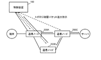
- FIG. 4 is a diagram illustrating an example of the topology construction operation by the control device.
- the control device 100 instructs the communication node 200C to transmit a topology confirmation packet
- the communication node 200C receives a topology confirmation packet from a port other than the port that has received the topology confirmation packet transmission instruction.
- the control device 100 instructs the transmission of the topology confirmation packet in which an appropriate VLAN is set, or by an instruction from the control device 100.
- Packet output may be excluded from the VLAN gate function.
- the control device 100 can construct the topology of the network configured by the communication nodes 200.
- the topology is not limited to the above-described method, and the topology can be detected using LLDP (Link Layer Discovery Protocol) or other routing protocols.
- control device 100 can automatically collect information on the ports provided in the communication node 200 and whether or not it has a VLAN gate function.
- the virtual network DB 106 is a database that holds configuration information of the virtual network configured by the communication node 200.
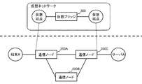
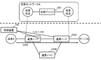
- FIG. 5 is a diagram illustrating a configuration example of a virtual network including the communication node 200 according to the first embodiment of this invention.
- a virtual network having a virtual bridge 300 virtually configured by controlling the communication nodes 200A to 200C is shown. Further, it is mapped to specific ports of the communication nodes 200A and 200C at the two end points of the virtual bridge.
- mapping the virtual network with the ports of the communication nodes 200A and 200C in this way a plurality of virtual networks logically divided from one physical network can be configured.
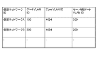
- FIG. 6 is an example of VLAN gate control information held in the virtual network DB 106 according to the first embodiment of this invention.
- a gate VLAN ID set on the terminal side for each virtual network, a gate VLAN ID set on the terminal side, a core VLAN ID set on a port connecting communication nodes, and a server-side gate VLAN ID are associated with each other.
- the number of flow entries set in the communication node 200 can be reduced by unifying the specific VLAN ID in the core network as described above. Further, the reduction in the number of flow entries contributes to easy implementation of the control device 100.
- the second VLAN information determination unit 104 Based on the virtual network configuration information held in the virtual network DB 106 described above and the topology information stored in the physical topology DB, the second VLAN information determination unit 104 (for example, in FIG. 5) The VLAN ID to be set to the port connected to the server A) is determined, and the determined VLAN ID is set to the corresponding port via the communication unit 108.
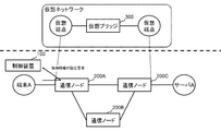
- FIG. 7 is a diagram illustrating an example of a VLAN setting operation by the second VLAN information determination unit 104.
- the communication node 200C is connected to the server A, and from the information stored in the virtual network DB 106, the connection port with the server A of the communication node 200C is the virtual network virtual network. It turns out that it is mapped to the end point.
- the second VLAN information determination unit 104 refers to the VLAN gate control information shown in FIG. 6 and sets “200” as the server-side gate VLAN ID to the connection port with the server A of the communication node 200C. I do.
- the second VLAN information determination unit 104 may perform a VLAN ID setting operation according to the updated contents. For example, when the server B is newly connected to the communication node 200C, the second VLAN information determination unit 104 connects the server side gate to the connection port with the server B of the communication node 200C as in the case of the server A described above. Set “200” as the VLAN ID. Further, when the server A is disconnected from the communication node 200C, an operation of deleting the VLAN ID from the connection port with the server A of the communication node 200C may be performed.
- the route calculation unit 101 When the route calculation unit 101 receives a control information setting request (a “Packet-In” message in Non-Patent Document 2) from the communication node 200 via the communication unit 108, the route calculation unit 101 is triggered by the control information setting request.
- the virtual network to which the transmission source terminal belongs is specified with reference to the packet reception port, the transmission source terminal ID, and the like.
- the path calculation unit 101 transfers the transfer path from the communication node serving as the starting point to the communication node 200 connected to the destination based on the packet information included in the control information setting request. Calculate
- the control information generation unit 102 generates control information (flow entry) to be set in the communication node on the calculated transfer route in order to transfer the packet on the transfer route calculated by the route calculation unit 101, and the communication unit The communication node 200 on the transfer path is set via the network 108. At the same time, the control information generation unit 102 sets the control information (flow entry) for executing necessary header rewriting in the communication node on the transfer path with reference to the VLAN gate control information shown in FIG.
- the first VLAN information determination unit 103 sets the port corresponding to the starting point of the route. Then, a VLAN ID corresponding to the specified virtual network is determined, and the determined VLAN ID is set to the corresponding port via the communication unit 108. Whether or not the port corresponding to the starting point of the route is a port that does not have a VLAN gate function is determined based on setting information (VLAN automatic setting target port information) stored in the control device 100 in advance by the network administrator. It may be determined, or may be determined based on the capability information of the communication node 200 collected from each communication node during the topology collection operation described above.
- each unit (processing means) of the control device 100 shown in FIG. 2 can also be realized by a computer program that causes a computer constituting the control device 100 to execute the above-described processes using its hardware.
- FIG. 8 to 14 are diagrams showing operations when terminal A is connected to communication node 200A and a packet addressed to server A is received from terminal A.
- FIG. 8 to 14 are diagrams showing operations when terminal A is connected to communication node 200A and a packet addressed to server A is received from terminal A.
- the communication node 200A that has received the packet addressed to the server A from the terminal A does not include control information having a matching condition that matches the packet addressed to the server A from the terminal A in the control information held by itself.
- a control information setting request (a “Packet-In” message in Non-Patent Document 2) is transmitted to the control device 100.
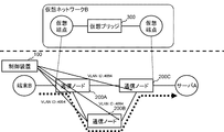
- the control device 100 that has received the control information setting request determines, for example, that the terminal A belongs to the virtual network A, and sends a packet from the communication node 200A to the server A via the communication node 200C as shown in FIG. Calculate the transfer route for transferring. Then, control information (flow entry) is set in the transfer nodes 200A and 200C on the transfer path to execute packet transfer according to the transfer path and rewrite of the VLAN ID corresponding to the VLAN gate control information. .
- the control device 100 sets the gate VLAN ID “100” of the virtual network A of the VLAN gate control information shown in FIG. 6 to the port that is the starting point of the calculated transfer path.
- control device 100 assigns the CORE VLAN ID “4094” of the virtual network A of the VLAN gate control information shown in FIG. 6 to the port connecting the communication nodes on the calculated transfer path. Set.
- the server-side gate VLAN ID “200” has been set by the second VLAN information determination unit 104 to the connection port with the server A of the communication node 200 ⁇ / b> C serving as the end point of the route. . Thus, preparation for packet transfer from the terminal A to the server A is completed.
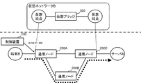
- the control device 100 calculates a transfer path for transferring a packet from the communication node 200A to the server A via the communication node 200B and the communication node 200C. Then, the control device 100 sets control information (flow entry) that causes the transfer nodes 200A to 200C on the transfer path to execute packet transfer according to the transfer path and rewrite of the VLAN ID. Furthermore, the control device 100 sets the gate VLAN ID “300” of the virtual network B in the VLAN gate control information shown in FIG. 6 to the port that is the starting point of the transfer path.
- control device 100 assigns the CORE VLAN ID “4094” of the virtual network B of the VLAN gate control information shown in FIG. 6 to the port connecting the communication nodes on the calculated transfer path. Set.
- the server-side gate VLAN ID “200” has already been set by the second VLAN information determination unit 104 to the connection port with the server A of the communication node 200 ⁇ / b> C serving as the end point of the route. . Thus, preparation for packet transfer from the terminal B to the server A is completed.
- FIG. 14 is a diagram showing a packet transfer path (bold solid line and bold broken line) realized by the above-described series of processing and a VLAN ID set to a port on the path.
- the VLAN ID necessary for the port of the communication node 200 on the route can be set simultaneously with the route setting by the control device 100.
- VLAN ID setting work for each communication node port is reduced.
- the set VLAN ID is used for the VLAN gate function in each communication node, the number of flow entries can be reduced and the responsiveness of the switch can be improved.
- the VLAN ID can be deleted when the control information (flow entry) set for each communication node 200 is deleted by a timeout due to the elapse of a certain period or by an explicit instruction from the control device 100.
- the VLAN ID is set in response to the reception of the control information setting request from the communication node.
- the connection of the terminal or the virtual machine to the communication node, the communication node It is also possible to adopt a form in which the VLAN ID is set in response to a topology change by addition.
- the VLAN gate function of the communication node 200 has been described as a function of discarding a packet for which specified VLAN information is not set at a specific port of the communication node when a packet is output.
- the communication node 200 may have a function of discarding the packet.
- the operation of the communication node 200 transmitting a control information setting request to the control device 100 when receiving a packet for which no VLAN information is set is also suppressed, so that the connection of the terminal or virtual machine to the communication node is suppressed. It is necessary to provide a mechanism for notifying the control apparatus 100 of a change in topology due to the addition of a communication node.
- the first VLAN information determination unit determines VLAN information when a port connected to the terminal is a port having a function of discarding a packet in which VLAN information designated at the time of packet transmission is not set.
- Control device In the control device of the first or second form, When the port connected to the terminal receives a packet in which the designated VLAN information is not set, the first VLAN information determination unit is a port having a function of discarding the packet. A control device that determines VLAN information.
- the VLAN setting unit A control device for setting VLAN information by transmitting a control message for executing an operation for setting the VLAN information to a designated port to the communication node to be controlled.
- VLAN information to be set in a port connected to an external device of the control target communication node is determined.
- a control device comprising a VLAN information determination unit.
- control device In the control device according to any one of the first to fifth aspects, Further, a control device that sets VLAN information in a port connecting the communication nodes to be controlled based on configuration information of the virtual network and topology information received from the communication node to be controlled. [Seventh form] In the control device according to any one of the first to sixth aspects, A control device that detects that a terminal or a virtual machine is connected by receiving a control information setting request from the communication node to be controlled.
Abstract
Priority Applications (4)
| Application Number | Priority Date | Filing Date | Title |
|---|---|---|---|
| CN201380068811.9A CN104885417A (zh) | 2012-12-28 | 2013-12-27 | 控制装置、通信系统、通信节点控制方法以及程序 |
| JP2014554582A JPWO2014104277A1 (ja) | 2012-12-28 | 2013-12-27 | 制御装置、通信システム、通信ノードの制御方法及びプログラム |
| US14/652,880 US10305811B2 (en) | 2012-12-28 | 2013-12-27 | Control apparatus, communication system, communication node control method, and program |
| EP13867412.2A EP2940937A4 (fr) | 2012-12-28 | 2013-12-27 | Appareil de commande, système de communication, procédé de commande de noeud de communication et programme |
Applications Claiming Priority (2)
| Application Number | Priority Date | Filing Date | Title |
|---|---|---|---|
| JP2012-288378 | 2012-12-28 | ||
| JP2012288378 | 2012-12-28 |
Publications (1)
| Publication Number | Publication Date |
|---|---|
| WO2014104277A1 true WO2014104277A1 (fr) | 2014-07-03 |
Family
ID=51021348
Family Applications (1)
| Application Number | Title | Priority Date | Filing Date |
|---|---|---|---|
| PCT/JP2013/085050 WO2014104277A1 (fr) | 2012-12-28 | 2013-12-27 | Appareil de commande, système de communication, procédé de commande de nœud de communication et programme |
Country Status (5)
| Country | Link |
|---|---|
| US (1) | US10305811B2 (fr) |
| EP (1) | EP2940937A4 (fr) |
| JP (1) | JPWO2014104277A1 (fr) |
| CN (1) | CN104885417A (fr) |
| WO (1) | WO2014104277A1 (fr) |
Cited By (3)
| Publication number | Priority date | Publication date | Assignee | Title |
|---|---|---|---|---|
| WO2016152903A1 (fr) * | 2015-03-24 | 2016-09-29 | 日本電気株式会社 | Système de communication, appareil de commande, procédé de commande et programme |
| JP2017536775A (ja) * | 2014-12-03 | 2017-12-07 | ゼットティーイー コーポレーションZte Corporation | 管理情報の伝送方法及びシステム |
| US10855524B2 (en) | 2014-09-05 | 2020-12-01 | Huawei Technologies Co., Ltd. | Method for NaaS device configuring service |
Families Citing this family (1)
| Publication number | Priority date | Publication date | Assignee | Title |
|---|---|---|---|---|
| JP6347177B2 (ja) * | 2014-08-22 | 2018-06-27 | 富士通株式会社 | 転送装置、制御装置、および、通信方法 |
Citations (2)
| Publication number | Priority date | Publication date | Assignee | Title |
|---|---|---|---|---|
| JPH09130421A (ja) * | 1995-11-02 | 1997-05-16 | Furukawa Electric Co Ltd:The | 仮想ネットワーク管理方法 |
| JP2001053776A (ja) * | 1999-08-06 | 2001-02-23 | Fujitsu Ltd | ネットワークシステム、スイッチ、および、サーバ |
Family Cites Families (11)
| Publication number | Priority date | Publication date | Assignee | Title |
|---|---|---|---|---|
| US7835367B2 (en) * | 2003-04-23 | 2010-11-16 | Fujitsu Limited | Network connection method, network connection system, and, layer 2 switch and management server forming the network connection system |
| US7830892B2 (en) | 2004-11-30 | 2010-11-09 | Broadcom Corporation | VLAN translation in a network device |
| US7688825B2 (en) * | 2005-04-12 | 2010-03-30 | Fujitsu Limited | Filtering frames at an input port of a switch |
| US7957325B2 (en) * | 2006-03-13 | 2011-06-07 | Alcatel Lucent | Method and network element configured for limiting the number virtual local area networks creatable by GVRP |
| US7792124B2 (en) * | 2007-04-01 | 2010-09-07 | Cisco Technology, Inc. | Data forwarding in a layer three satellite network |
| US10848347B2 (en) | 2007-08-31 | 2020-11-24 | Level 3 Communications, Llc | Managing virtual local area network domains |
| WO2011074516A1 (fr) * | 2009-12-15 | 2011-06-23 | 日本電気株式会社 | Système de réseau, sa méthode de gestion et contrôleur |
| JP5673557B2 (ja) * | 2010-01-04 | 2015-02-18 | 日本電気株式会社 | ネットワークシステム、コントローラ、ネットワーク制御方法 |
| US8718071B2 (en) * | 2010-09-10 | 2014-05-06 | Futurewei Technologies, Inc. | Method to pass virtual local area network information in virtual station interface discovery and configuration protocol |
| JP5370592B2 (ja) | 2011-04-18 | 2013-12-18 | 日本電気株式会社 | 端末、制御装置、通信方法、通信システム、通信モジュール、プログラムおよび情報処理装置 |
| CA2775804C (fr) * | 2012-05-08 | 2013-01-29 | Guest Tek Interactive Entertainment Ltd. | Reseau informatise a configuration automatique a des etablissement d'accueil avec reglages specialement destines aux reservations |
-
2013
- 2013-12-27 WO PCT/JP2013/085050 patent/WO2014104277A1/fr active Application Filing
- 2013-12-27 CN CN201380068811.9A patent/CN104885417A/zh active Pending
- 2013-12-27 JP JP2014554582A patent/JPWO2014104277A1/ja active Pending
- 2013-12-27 US US14/652,880 patent/US10305811B2/en not_active Expired - Fee Related
- 2013-12-27 EP EP13867412.2A patent/EP2940937A4/fr not_active Withdrawn
Patent Citations (2)
| Publication number | Priority date | Publication date | Assignee | Title |
|---|---|---|---|---|
| JPH09130421A (ja) * | 1995-11-02 | 1997-05-16 | Furukawa Electric Co Ltd:The | 仮想ネットワーク管理方法 |
| JP2001053776A (ja) * | 1999-08-06 | 2001-02-23 | Fujitsu Ltd | ネットワークシステム、スイッチ、および、サーバ |
Non-Patent Citations (3)
| Title |
|---|
| NICK MCKEOWN, OPENFLOW: ENABLING INNOVATION IN CAMPUS NETWORKS, 24 November 2012 (2012-11-24), Retrieved from the Internet <URL:http://www.openflow.org/documents/openflow-wp-latest.pdf> |
| OPENFLOW SWITCH SPECIFICATION, 11 December 2012 (2012-12-11), Retrieved from the Internet <URL:https://www.opennetworking.org/images/stories/downloads/specificatio n/openflow-spec-v 1 .3 .1 .pdf> |
| See also references of EP2940937A4 |
Cited By (7)
| Publication number | Priority date | Publication date | Assignee | Title |
|---|---|---|---|---|
| US10855524B2 (en) | 2014-09-05 | 2020-12-01 | Huawei Technologies Co., Ltd. | Method for NaaS device configuring service |
| US11196620B2 (en) | 2014-09-05 | 2021-12-07 | Huawei Technologies Co., Ltd. | Method and apparatus for NaaS device configuring service |
| US11552841B2 (en) | 2014-09-05 | 2023-01-10 | Huawei Technologies Co., Ltd. | Method and apparatus for configuring service |
| JP2017536775A (ja) * | 2014-12-03 | 2017-12-07 | ゼットティーイー コーポレーションZte Corporation | 管理情報の伝送方法及びシステム |
| WO2016152903A1 (fr) * | 2015-03-24 | 2016-09-29 | 日本電気株式会社 | Système de communication, appareil de commande, procédé de commande et programme |
| JPWO2016152903A1 (ja) * | 2015-03-24 | 2018-01-18 | 日本電気株式会社 | 通信システム、制御装置、制御方法及びプログラム |
| US10348623B2 (en) | 2015-03-24 | 2019-07-09 | Nec Corporation | Communication system, control apparatus, control method and program |
Also Published As
| Publication number | Publication date |
|---|---|
| US20150334032A1 (en) | 2015-11-19 |
| EP2940937A1 (fr) | 2015-11-04 |
| EP2940937A4 (fr) | 2016-08-24 |
| US10305811B2 (en) | 2019-05-28 |
| CN104885417A (zh) | 2015-09-02 |
| JPWO2014104277A1 (ja) | 2017-01-19 |
Similar Documents
| Publication | Publication Date | Title |
|---|---|---|
| US20180324274A1 (en) | Information system, control apparatus, method of providing virtual network, and program | |
| JP5987920B2 (ja) | 通信システム、制御装置及びネットワークトポロジの管理方法 | |
| JP5652565B2 (ja) | 情報システム、制御装置、通信方法およびプログラム | |
| US20130195110A1 (en) | Communication system, control device, method for setting processing rules, and program | |
| JP5939353B2 (ja) | 制御装置、通信システム、スイッチ制御方法及びプログラム | |
| US20130148666A1 (en) | Communication system, controller, node controlling method and program | |
| JP2013232905A (ja) | 通信システム、制御装置、通信方法及びプログラム | |
| JP5818268B2 (ja) | 通信システム、制御装置、経路制御方法およびプログラム | |
| WO2011118574A1 (fr) | Système de communication, dispositif de contrôle, procédé de mesure de retard et programme | |
| WO2014104277A1 (fr) | Appareil de commande, système de communication, procédé de commande de nœud de communication et programme | |
| US20150256455A1 (en) | Communication system, path information exchange apparatus, communication node, forwarding method for path information and program | |
| US9614758B2 (en) | Communication system, integrated controller, packet forwarding method and program | |
| JP5747997B2 (ja) | 制御装置、通信システム、仮想ネットワークの管理方法およびプログラム | |
| JP6206493B2 (ja) | 制御装置、通信システム、中継装置の制御方法及びプログラム | |
| WO2014084216A1 (fr) | Dispositif de commande, système de communication, méthode et programme de communication | |
| WO2014119602A1 (fr) | Appareil de commande, commutateur, système de communication, procédé de commande de commutateur et programme | |
| WO2014087993A1 (fr) | Appareil de commande, système de communication, procédé de communication et programme | |
| JP2016225933A (ja) | 制御装置、中継装置の制御方法、プログラム及び通信システム |
Legal Events
| Date | Code | Title | Description |
|---|---|---|---|
| 121 | Ep: the epo has been informed by wipo that ep was designated in this application |
Ref document number: 13867412 Country of ref document: EP Kind code of ref document: A1 |
|
| REEP | Request for entry into the european phase |
Ref document number: 2013867412 Country of ref document: EP |
|
| WWE | Wipo information: entry into national phase |
Ref document number: 2013867412 Country of ref document: EP |
|
| WWE | Wipo information: entry into national phase |
Ref document number: 14652880 Country of ref document: US |
|
| ENP | Entry into the national phase |
Ref document number: 2014554582 Country of ref document: JP Kind code of ref document: A |
|
| NENP | Non-entry into the national phase |
Ref country code: DE |