EP2940937A1 - Appareil de commande, système de communication, procédé de commande de noeud de communication et programme - Google Patents
Appareil de commande, système de communication, procédé de commande de noeud de communication et programme Download PDFInfo
- Publication number
- EP2940937A1 EP2940937A1 EP13867412.2A EP13867412A EP2940937A1 EP 2940937 A1 EP2940937 A1 EP 2940937A1 EP 13867412 A EP13867412 A EP 13867412A EP 2940937 A1 EP2940937 A1 EP 2940937A1
- Authority
- EP
- European Patent Office
- Prior art keywords
- port
- vlan
- communication node
- information
- terminal
- Prior art date
- Legal status (The legal status is an assumption and is not a legal conclusion. Google has not performed a legal analysis and makes no representation as to the accuracy of the status listed.)
- Withdrawn
Links
Images


Classifications
-
- H—ELECTRICITY
- H04—ELECTRIC COMMUNICATION TECHNIQUE
- H04L—TRANSMISSION OF DIGITAL INFORMATION, e.g. TELEGRAPHIC COMMUNICATION
- H04L47/00—Traffic control in data switching networks
- H04L47/10—Flow control; Congestion control
- H04L47/32—Flow control; Congestion control by discarding or delaying data units, e.g. packets or frames
-
- H—ELECTRICITY
- H04—ELECTRIC COMMUNICATION TECHNIQUE
- H04L—TRANSMISSION OF DIGITAL INFORMATION, e.g. TELEGRAPHIC COMMUNICATION
- H04L12/00—Data switching networks
- H04L12/28—Data switching networks characterised by path configuration, e.g. LAN [Local Area Networks] or WAN [Wide Area Networks]
- H04L12/46—Interconnection of networks
- H04L12/4641—Virtual LANs, VLANs, e.g. virtual private networks [VPN]
-
- H—ELECTRICITY
- H04—ELECTRIC COMMUNICATION TECHNIQUE
- H04L—TRANSMISSION OF DIGITAL INFORMATION, e.g. TELEGRAPHIC COMMUNICATION
- H04L12/00—Data switching networks
- H04L12/28—Data switching networks characterised by path configuration, e.g. LAN [Local Area Networks] or WAN [Wide Area Networks]
- H04L12/46—Interconnection of networks
- H04L12/4604—LAN interconnection over a backbone network, e.g. Internet, Frame Relay
- H04L12/462—LAN interconnection over a bridge based backbone
- H04L12/4625—Single bridge functionality, e.g. connection of two networks over a single bridge
-
- H—ELECTRICITY
- H04—ELECTRIC COMMUNICATION TECHNIQUE
- H04L—TRANSMISSION OF DIGITAL INFORMATION, e.g. TELEGRAPHIC COMMUNICATION
- H04L45/00—Routing or path finding of packets in data switching networks
- H04L45/02—Topology update or discovery
Definitions
- the present invention relates to a control apparatus, a communication system, a communication node control method, and a program.
- a control apparatus that controls communication nodes in a centralized manner; a communication system; a communication node control method; and a program.
- Non-patent Literatures 1 and 2 a technique referred to as OpenFlow has been proposed. OpenFlow recognizes communications as end-to-end flows and performs path control, failure recovery, load balancing, and optimization on a per-flow basis.
- Each OpenFlow switch according to Non-patent Literature 2 has a secure channel for communication with an OpenFlow controller and operates according to a flow table suitably added or rewritten by the OpenFlow controller. In the flow table, a set of the following three is defined for each flow: match conditions (Match Fields) against which a packet header is matched; flow statistical information (Counters); and instructions that define at least one processing content (see section "5.2 Flow Table" in Non-patent Literature 2).
- the OpenFlow switch searches the flow table for an entry having a match condition that matches header information of the received packet (see "5.3 "Matching" in Non-patent Literature 2). If, as a result of the search, the OpenFlow switch finds an entry that matches the received packet, the OpenFlow switch updates the flow statistical information (Counters) and processes the received packet on the basis of a processing content(s) (packet transmission from a specified port, flooding, dropping, etc.) written in the Instructions field of the entry. If, as a result of the search, the OpenFlow switch does not find an entry that matches the received packet, the OpenFlow switch transmits an entry setting request to the OpenFlow controller via the secure channel.
- the OpenFlow switch transmits an entry setting request to the OpenFlow controller via the secure channel.
- the OpenFlow switch requests the OpenFlow controller to transmit control information for processing the received packet (Packet-In message).
- the OpenFlow switch receives a flow entry that defines a processing content(s) and updates the flow table. In this way, by using an entry stored in the flow table as control information, the OpenFlow switch performs packet forwarding.
- Example 2 in Non-patent Literature 1 describes that a virtual network such as a VLAN (Virtual Local Area Network) can be established by combining OpenFlow switches and an OpenFlow controller that controls the OpenFlow switches in a centralized manner.
- VLAN Virtual Local Area Network
- Non-patent Literature 2 describes that a control message for an additional function, which is referred to as an "Expermenter message,” can be exchanged between the OpenFlow controller and an OpenFlow switch ("A.5.4 Expermenter" in Non-patent Literature 2).
- Non-patent Literatures 1 and 2 disclose that a virtual network can be established by setting VLAN information as match conditions in entries stored in flow tables in OpenFlow switches (which will simply be referred to as a "switch,” as needed), respectively.
- Some of the switches whose port needs to be associated with appropriate VLAN information include a function of dropping a packet including VLAN information inappropriate in relation to a corresponding egress port.
- some switches include a function of dropping, when receiving a packet in which specified VLAN information is not set, the packet.
- These functions can be used in place of flow entries for dropping packets having VLAN information inappropriate in relation to a port. Thus, these functions contribute to reducing the number of flow entries stored in each switch and improving the response of each switch.
- An object of the present invention is to provide a control apparatus, a communication system, a communication node control method, and a program that contribute to reducing the labor required for setting VLAN information in the ports of the communication nodes in a centralized-control-type communication system as typified by a system using the above OpenFlow.
- a control apparatus including: a connection detection unit configured to detect connection of a terminal or a virtual machine to a control target communication node; a first VLAN information determination unit configured to determine VLAN (Virtual Local Area Network) information that is set in a port of the communication node, the port having been connected to the terminal or the virtual machine, on the basis of a virtual network to which the detected terminal or virtual machine belongs; and a VLAN information setting unit configured to set the determined VLAN information in the port.
- VLAN Virtual Local Area Network
- a communication system including: a communication node configured to include a function of dropping, when receiving an instruction for transmitting a packet in which specified VLAN (Virtual Local Area Network) information is not set via a certain port, the packet or a function of dropping, when receiving a packet in which specified VLAN information is not set via a certain port, the packet; and a control apparatus, including: a connection detection unit configured to detect connection of a terminal or a virtual machine to the specified port of the communication node; a first VLAN information determination unit configured to determine VLAN information that is set in a port of the communication node, the port having been connected to the terminal or the virtual machine, on the basis of a virtual network to which the detected terminal or virtual machine belongs; and a VLAN information setting unit configured to set the determined VLAN information in the port.
- VLAN Virtual Local Area Network
- a communication node control method including steps of: detecting connection of a terminal or a virtual machine to a control target communication node; determining VLAN (Virtual Local Area Network) information that is set in a port of the communication node, the port having been connected to the terminal or the virtual machine, on the basis of a virtual network to which the detected terminal or virtual machine belongs; and setting the determined VLAN information in the port.
- This method is associated with a certain machine, namely, with a control apparatus that sets VLAN information in ports of communication nodes.
- a program causing a computer that controls communication nodes to execute processing for: detecting connection of a terminal or a virtual machine to a control target communication node; determining VLAN (Virtual Local Area Network) information that is set in a port of the communication node, the port having been connected to the terminal or the virtual machine, on the basis of a virtual network to which the detected terminal or virtual machine belongs; and setting the determined VLAN information in the port.
- This program can be recorded in a computer-readable (non-transient) storage medium.
- the present invention can be embodied as a computer program product.
- the present invention contributes to reducing the labor required for setting VLAN information in the ports of the communication nodes in a centralized-control-type communication system.
- an exemplary embodiment of the present invention can be realized by a configuration including: a plurality of communication nodes 20; and a control apparatus 10 that controls these communication nodes 20. More specifically, the control apparatus 10 includes: a connection detection unit 11 configured to detect connection of a terminal or a virtual machine to a control target communication node 20; a first VLAN information determination unit 12 configured to determine VLAN (Virtual Local Area Network) information that is set in a port of the communication node, the port having been connected to the terminal or the virtual machine, on the basis of a virtual network to which the detected terminal or virtual machine belongs; and a VLAN information setting unit 13 configured to set the determined VLAN information in the port.
- VLAN Virtual Local Area Network
- a control message for an additional function which is referred to as an "Expermenter message" in Non-patent Literature 2
- a network setting protocol such as NETCONF
- the VLAN information may be set via an external system.
- VLAN information is set in a communication node port to which a terminal or a virtual machine has been connected. Namely, when connection of an unknown terminal or virtual machine to a communication node is detected, appropriate VLAN information is automatically set. Thus, the labor on the network administrator or the like can be reduced.
- connection detection unit 11 may be notified by each communication node of reception of a new packet.
- the connection detection unit 11 may be notified by a virtual network management apparatus, a virtual machine management apparatus, or the like.
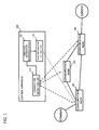
- Fig. 2 illustrates a configuration of a communication system according to a first exemplary embodiment of the present invention.
- Fig. 2 illustrates a plurality of communication nodes 200A to 200C that are connected to each other to configure a network (any one of the communication nodes 200A to 200C will be referred to as a "communication node 200" unless the communication nodes 200A to 200C need to be distinguished from each other), a control apparatus 100 that controls the network by setting control information in these communication nodes 200, and a terminal and a server that communicate with each other via the network configured by the communication nodes 200.
- Each communication node 200 processes a packet by referring to its own flow entry that is set as control information.
- An OpenFlow switch in Non-patent Literature 2 can be used as each communication node.
- each communication node 200 according to the present exemplary embodiment includes a function of dropping a packet, to which specified VLAN information is not set, instead of outputting the packet from a certain port (this function will be referred to as a "VLAN gate function").
- Each communication node 200 may be a physical switch or a virtual switch that operates on a virtual server or the like.
- the control apparatus 100 controls the communication nodes 200 by setting flow entries as control information in the communication nodes 200.
- the OpenFlow controller in Non-patent Literature 2 can be used as the control apparatus.
- Fig. 3 is a block diagram illustrating a configuration of the control apparatus 100 according to the first exemplary embodiment of the present invention.
- the control apparatus 100 includes a path calculation unit 101, a control information generation unit 102, a first VLAN information determination unit 103, a second VLAN information determination unit 104, a topology establishment unit 105, a virtual network database (virtual network DB) 106, a physical topology database (physical topology DB) 107, and a communication unit 108 that exchanges various types of control messages with each communication node 200 (corresponding to the above VLAN information setting unit 13).
- the topology establishment unit 105 causes the communication nodes 200 to transmit topology check packets via the communication unit 108. On the basis of the result of this operation, the topology establishment unit 105 establishes a network topology configured by the communication nodes 200 and stores the topology in the physical topology database (physical topology DB) 107.
- the physical topology database physical topology DB
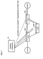
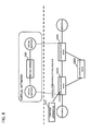
- Fig. 4 illustrates an exemplary topology establishment operation performed by the control apparatus.
- the control apparatus 100 transmits a topology check packet transmission instruction to the communication node 200C
- the communication node 200C transmits a topology check packet from each of the ports other than the port that has received the topology check packet transmission instruction (if any one of the ports outputting a topology check packet includes the VLAN gate function, the control apparatus 100 may instruct transmission of a topology check packet in which appropriate VLAN information is set or outputting of a packet instructed by the control apparatus 100 may be exempt from the VLAN gate function).
- the control apparatus 100 can establish the network topology configured by the communication nodes 200.
- the control apparatus 100 may establish the network topology by using a method other than the above method.
- the control apparatus 100 may detect the topology by using LLDP (Link Layer Discovery Protocol) or another routing protocol.
- LLDP Link Layer Discovery Protocol
- control apparatus 100 collect information about the capability of each communication node 200, in addition to the information about the topology of the communication nodes 200. In this way, the control apparatus 100 can automatically collect information about the ports of the communication nodes 200 and whether each port includes the VLAN gate function.
- the virtual network DB 106 is a database storing information about a configuration of a virtual network configured by communication nodes 200.
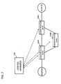
- Fig. 5 illustrates an exemplary configuration of a virtual network configured by communication nodes 200 according to the first exemplary embodiment of the present invention.
- a virtual network including a virtual bridge 300 virtually configured by controlling the communication nodes 200A to 200C is illustrated.
- Two endpoints of the virtual bridge are mapped with certain ports of the communication nodes 200A and 200C.
- Fig. 6 illustrates exemplary VLAN gate control information stored in the virtual network DB 106 according to the first exemplary embodiment of the present invention.
- a gate VLAN ID set on each terminal side, a core VLAN ID set in ports connecting communication nodes, and a server-side gate VLAN ID are associated with each other per virtual network.
- a communication through a virtual network A whose VLAN ID is 100 and a communication through a virtual network B whose VLAN ID is 300 are aggregated to a communication having a shared core VLAN ID of 4094 in a core network configured by the communication nodes 200A to 200C.
- the VLAN ID of 4094 needs to be set in a core-network-side port of an entry-side communication node.
- the entry-side communication node can drop a packet which is addressed to a destination beyond the core network and which does not indicate the VLAN ID of 4094.
- the VLAN ID of 200 needs to be set in a port of an exit-side communication node, the port being connected to the server.
- an exit-side communication node can drop a packet which is addressed to the server side and which does not indicate the VLAN ID of 200.
- the number of flow entries set in the communication nodes 200 can be reduced.
- the reduction in the number of flow entries makes it easier to implement the control apparatus 100.
- the second VLAN information determination unit 104 determines a VLAN ID that is set in a port of a communication node 200, the port having been connected to an external apparatus (for example, the server A in Fig. 5 ), and sets the determined VLAN ID in the port via the communication unit 108.
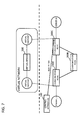
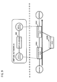
- Fig. 7 illustrates an exemplary VLAN information setting operation performed by the second VLAN information determination unit 104.
- the communication node 200C is connected to the server A.
- the port of the communication node 200C, the port connected to the server A is mapped with a virtual endpoint of the virtual network.
- the second VLAN information determination unit 104 refers to the VLAN gate control information illustrated in Fig. 6 and sets "200" as a server-side gate VLAN ID in the port of the communication node 200C, the port connected to the server A.
- the second VLAN information determination unit 104 may set a VLAN ID on the basis of the updated content. For example, if a server B is newly connected to the communication node 200C, the second VLAN information determination unit 104 sets "200" as a server-side gate VLAN ID in a port of the communication node 200C, the port having been connected to the server B, as with the case of the above server A. In addition, if the server A is disconnected from the communication node 200C, the VLAN ID may be deleted from the port of the communication node 200C, the port having been disconnected from the server A.
- the path calculation unit 101 When receiving a control information setting request from a communication node 200 via the communication unit 108 ("Packet-In" message in Non-patent Literature 2), the path calculation unit 101 refers to information about the port that has received the packet which causes the communication node 200 to transmit the control information setting request, an ID of the source terminal, and the like and determines a virtual network to which the source terminal belongs. Next, if the virtual network is determined, the path calculation unit 101 calculates a forwarding path from the start-point communication node to a communication node 200 connected to the destination, on the basis of the packet information included in the control information setting request.
- control information generation unit 102 To realize packet forwarding on the forwarding path calculated by the path calculation unit 101, the control information generation unit 102 generates and sets control information (flow entries) to be set in the relevant communication nodes 200 on the calculated forwarding path via the communication unit 108.
- control information generation unit 102 refers to the VLAN gate control information illustrated in Fig. 6 and sets control information (flow entries) for performing necessary header rewriting in the communication nodes on the forwarding path.
- the first VLAN information determination unit 103 determines a VLAN ID corresponding to the determined virtual network for the port serving as the start point of the path and sets the determined VLAN ID in the port via the communication unit 108.
- Whether the port serving as the start point of the path includes the VLAN gate function may be determined on the basis of setting information (port information indicating automatic VLAN setting) stored in advance in the control apparatus 100 by a network administrator or on the basis of the information about the capability of each communication node 200 collected from each communication node when the above topology collection operation is performed.
- Each unit (processing means) of the control apparatus 100 illustrated in Fig. 2 may be realized by a computer program which causes a computer that constitutes the control apparatus 100 to use its hardware and execute the corresponding processing described above.
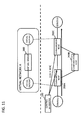
- FIGs. 8 to 14 illustrate an operation performed when the terminal A has been connected to the communication node 200A and the communication node 200A has received a packet addressed to the server A from the terminal A.
- the communication node 200A When receiving the packet addressed to the server A from the terminal A, the communication node 200A determines that the control information stored therein does not include control information having a match condition(s) that matches the packet addressed to the server A from the terminal A. Thus, as illustrated in Fig. 8 , the communication node 200A transmits a control information setting request ("Packet-In" message Non-patent Literature 2) to the control apparatus 100.
- a control information setting request (“Packet-In" message Non-patent Literature 2
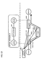
- the control apparatus 100 After receiving the control information setting request, for example, the control apparatus 100 determines that the terminal A belongs to the virtual network A and calculates a forwarding path for forwarding the packet from the communication node 200A to the server A via the communication node 200C, as illustrated in Fig. 9 . Next, the control apparatus 100 sets control information (flow entries) for forwarding the packet on the forwarding path and performing rewriting of VLAN IDs on the basis of the VLAN gate control information in the forwarding nodes 200A and 200C on the forwarding path.
- control information flow entries
- the control apparatus 100 allocates "100" to the port serving as the start point of the calculated forwarding path as the gate VLAN ID of the virtual network A as indicated in the VLAN gate control information in Fig. 6 .
- control apparatus 100 allocates "4094" to the ports connecting the communication nodes on the calculated forwarding path as the CORE VLAN ID of the virtual network A as indicated in the VLAN gate control information in Fig. 6 .
- the control apparatus 100 also calculates a forwarding path for forwarding the packet from the communication node 200A to the server A via the communication nodes 200B and 200C, as illustrated in Fig. 12 .
- the control apparatus 100 sets control information (flow entries) for forwarding the packet on the forwarding path and performing rewriting of VLAN IDs in the forwarding nodes 200A to 200C on the forwarding path.
- the control apparatus 100 allocates "300" to the port serving as the start point of the forwarding path as the gate VLAN ID of the virtual network B as indicated in the VLAN gate control information in Fig. 6 .
- control apparatus 100 allocates "4094" in the ports connecting the communication nodes on the calculated forwarding path as the CORE VLAN ID of the virtual network B as indicated in the VLAN gate control information in Fig. 6 .
- Fig. 14 illustrates packet forwarding paths (a bold solid line and a bold dashed line) realized by the above series of operations and the VLAN IDs set in the ports on the paths.
- VLAN IDs necessary for the relevant ports of the communication nodes 200 on the path can be set simultaneously.
- the labor required for setting the VLAN IDs in the relevant ports of each communication node is reduced.
- these communication nodes use the set VLAN IDs as the VLAN gate functions, respectively, the number of flow entries is reduced and the response of each switch is improved.
- VLAN IDs set in the ports of the communication nodes 200 by the control apparatus 100 be deleted at appropriate timing.
- a VLAN ID may be deleted after a certain time period elapses (time-out) or when control information (flow entry) set in a communication node 200 is deleted by an explicit instruction from the control apparatus 100.
- control apparatus 100 may set VLAN IDs when the topology is changed by connection of a terminal or a virtual machine to a communication node or addition of a communication node, for example.
- each communication node 200 has a function of dropping a packet in which specified VLAN information is not set instead of outputting the packet from a certain port of the communication node 200 as the VLAN gate of each communication node 200.
- each communication node 200 may have a function of dropping, when receiving a packet in which specified VLAN information is not set, the packet.
- transmission of a control information setting request from the communication node 200 to the control apparatus 100 is prevented.
- the control apparatus according to mode 1 ; wherein the first VLAN information determination unit determines the VLAN information if the port to which the terminal has been connected includes a function of dropping a packet in which specified VLAN information is not set instead of transmitting the packet.
- the control apparatus according to mode 1 or 2; wherein the first VLAN information determination unit determines the VLAN information if the port to which the terminal has been connected includes a function of dropping, when receiving a packet in which specified VLAN information is not set, the packet.
- the control apparatus according to any one of modes 1 to 3; wherein the VLAN information setting unit sets the VLAN information by transmitting a control message for causing the control target communication node to set the VLAN information in a specified port.
- control apparatus according to any one of modes 1 to 4, further including:
- control apparatus according to any one of modes 1 to 5; wherein, on the basis of the virtual network configuration information and the topology information received from the control target communication node, VLAN information is set in ports connecting control target communication nodes.
- connection detection unit detects connection of a terminal or a virtual machine by receiving a control information setting request from the control target communication node.
- Modes 8 to 10 can be expanded in the same way as mode 1 is expanded to modes 2 to 7.
- Non-patent Literatures The disclosure of each of the above Non-patent Literatures is incorporated herein by reference thereto. Modifications and adjustments of the exemplary embodiments and the examples are possible within the scope of the overall disclosure (including the claims) of the present invention and based on the basic technical concept of the present invention. In addition, various combinations and selections of various disclosed elements (including the elements in each of the claims, exemplary embodiments, examples, drawings, etc.) are possible within the scope of the claims of the present invention. Namely, the present invention of course includes various variations and modifications that could be made by those skilled in the art according to the overall disclosure including the claims and the technical concept. In particular, the present description discloses numerical value ranges. However, even if the description does not particularly disclose arbitrary numerical values or small ranges included in the ranges, these values and ranges should be deemed to have been specifically disclosed.
Applications Claiming Priority (2)
| Application Number | Priority Date | Filing Date | Title |
|---|---|---|---|
| JP2012288378 | 2012-12-28 | ||
| PCT/JP2013/085050 WO2014104277A1 (fr) | 2012-12-28 | 2013-12-27 | Appareil de commande, système de communication, procédé de commande de nœud de communication et programme |
Publications (2)
| Publication Number | Publication Date |
|---|---|
| EP2940937A1 true EP2940937A1 (fr) | 2015-11-04 |
| EP2940937A4 EP2940937A4 (fr) | 2016-08-24 |
Family
ID=51021348
Family Applications (1)
| Application Number | Title | Priority Date | Filing Date |
|---|---|---|---|
| EP13867412.2A Withdrawn EP2940937A4 (fr) | 2012-12-28 | 2013-12-27 | Appareil de commande, système de communication, procédé de commande de noeud de communication et programme |
Country Status (5)
| Country | Link |
|---|---|
| US (1) | US10305811B2 (fr) |
| EP (1) | EP2940937A4 (fr) |
| JP (1) | JPWO2014104277A1 (fr) |
| CN (1) | CN104885417A (fr) |
| WO (1) | WO2014104277A1 (fr) |
Cited By (1)
| Publication number | Priority date | Publication date | Assignee | Title |
|---|---|---|---|---|
| US10348623B2 (en) | 2015-03-24 | 2019-07-09 | Nec Corporation | Communication system, control apparatus, control method and program |
Families Citing this family (3)
| Publication number | Priority date | Publication date | Assignee | Title |
|---|---|---|---|---|
| JP6347177B2 (ja) * | 2014-08-22 | 2018-06-27 | 富士通株式会社 | 転送装置、制御装置、および、通信方法 |
| CN105471609B (zh) | 2014-09-05 | 2019-04-05 | 华为技术有限公司 | 一种用于配置业务的方法和装置 |
| CN105656746A (zh) * | 2014-12-03 | 2016-06-08 | 中兴通讯股份有限公司 | 一种管理信息的传送方法和系统 |
Family Cites Families (13)
| Publication number | Priority date | Publication date | Assignee | Title |
|---|---|---|---|---|
| JPH09130421A (ja) * | 1995-11-02 | 1997-05-16 | Furukawa Electric Co Ltd:The | 仮想ネットワーク管理方法 |
| JP4148605B2 (ja) * | 1999-08-06 | 2008-09-10 | 富士通株式会社 | ネットワークシステムおよびサーバ |
| US7835367B2 (en) * | 2003-04-23 | 2010-11-16 | Fujitsu Limited | Network connection method, network connection system, and, layer 2 switch and management server forming the network connection system |
| US7830892B2 (en) | 2004-11-30 | 2010-11-09 | Broadcom Corporation | VLAN translation in a network device |
| US7688825B2 (en) * | 2005-04-12 | 2010-03-30 | Fujitsu Limited | Filtering frames at an input port of a switch |
| US7957325B2 (en) * | 2006-03-13 | 2011-06-07 | Alcatel Lucent | Method and network element configured for limiting the number virtual local area networks creatable by GVRP |
| US7792124B2 (en) * | 2007-04-01 | 2010-09-07 | Cisco Technology, Inc. | Data forwarding in a layer three satellite network |
| US10848347B2 (en) * | 2007-08-31 | 2020-11-24 | Level 3 Communications, Llc | Managing virtual local area network domains |
| WO2011074516A1 (fr) * | 2009-12-15 | 2011-06-23 | 日本電気株式会社 | Système de réseau, sa méthode de gestion et contrôleur |
| WO2011081020A1 (fr) * | 2010-01-04 | 2011-07-07 | 日本電気株式会社 | Système de réseau, organe de commande, procédé de commande de réseau |
| US8953621B2 (en) | 2010-09-10 | 2015-02-10 | Futurewei Technologies, Inc. | Specifying priority on a virtual station interface discovery and configuration protocol response |
| WO2012144190A1 (fr) * | 2011-04-18 | 2012-10-26 | Nec Corporation | Terminal, dispositif de commande, procédé de communication, système de communication, module de communication, programme, et dispositif de traitement d'informations |
| CA2775804C (fr) * | 2012-05-08 | 2013-01-29 | Guest Tek Interactive Entertainment Ltd. | Reseau informatise a configuration automatique a des etablissement d'accueil avec reglages specialement destines aux reservations |
-
2013
- 2013-12-27 CN CN201380068811.9A patent/CN104885417A/zh active Pending
- 2013-12-27 EP EP13867412.2A patent/EP2940937A4/fr not_active Withdrawn
- 2013-12-27 WO PCT/JP2013/085050 patent/WO2014104277A1/fr active Application Filing
- 2013-12-27 JP JP2014554582A patent/JPWO2014104277A1/ja active Pending
- 2013-12-27 US US14/652,880 patent/US10305811B2/en not_active Expired - Fee Related
Cited By (1)
| Publication number | Priority date | Publication date | Assignee | Title |
|---|---|---|---|---|
| US10348623B2 (en) | 2015-03-24 | 2019-07-09 | Nec Corporation | Communication system, control apparatus, control method and program |
Also Published As
| Publication number | Publication date |
|---|---|
| EP2940937A4 (fr) | 2016-08-24 |
| US20150334032A1 (en) | 2015-11-19 |
| WO2014104277A1 (fr) | 2014-07-03 |
| JPWO2014104277A1 (ja) | 2017-01-19 |
| CN104885417A (zh) | 2015-09-02 |
| US10305811B2 (en) | 2019-05-28 |
Similar Documents
| Publication | Publication Date | Title |
|---|---|---|
| US11190435B2 (en) | Control apparatus, communication system, tunnel endpoint control method, and program | |
| US9515868B2 (en) | System and method for communication | |
| US9843496B2 (en) | Communication system, control apparatus, and network topology management method | |
| US10645006B2 (en) | Information system, control apparatus, communication method, and program | |
| US20160315845A1 (en) | SDN Controller, Data Center System, and Routing Connection Method | |
| EP2487842A1 (fr) | Système informatique et procédé de surveillance pour système informatique | |
| US20150249600A1 (en) | Communication system, control apparatus, packet forwarding path control method, and program | |
| EP2157746A1 (fr) | Système de commande de routage dans un L3VPN réseau de service | |
| US20130195110A1 (en) | Communication system, control device, method for setting processing rules, and program | |
| EP2879335A1 (fr) | Dispositif de contrôle, système de communication, procédé de communication, et programme | |
| US9832114B2 (en) | Packet forwarding system, control apparatus, packet forwarding method, and program | |
| EP2940937A1 (fr) | Appareil de commande, système de communication, procédé de commande de noeud de communication et programme | |
| WO2011118574A1 (fr) | Système de communication, dispositif de contrôle, procédé de mesure de retard et programme | |
| EP2991286A1 (fr) | Noeud de communication, système de communication, méthode de traitement de paquet et programme | |
| EP2916497A1 (fr) | Système de communication, dispositif d'échange d'informations de voie, noeud de communication, procédé de transfert pour informations de voie et programme | |
| US10742539B2 (en) | Control apparatus, communication system, relay apparatus control method, and program | |
| US10044671B2 (en) | Control apparatus, communication system, communication method, and program | |
| EP3116176A1 (fr) | Système de communication, dispositif de commande, dispositif de communication et procédé de communication | |
| US20150372900A1 (en) | Communication system, control apparatus, communication control method, and program |
Legal Events
| Date | Code | Title | Description |
|---|---|---|---|
| PUAI | Public reference made under article 153(3) epc to a published international application that has entered the european phase |
Free format text: ORIGINAL CODE: 0009012 |
|
| 17P | Request for examination filed |
Effective date: 20150702 |
|
| AK | Designated contracting states |
Kind code of ref document: A1 Designated state(s): AL AT BE BG CH CY CZ DE DK EE ES FI FR GB GR HR HU IE IS IT LI LT LU LV MC MK MT NL NO PL PT RO RS SE SI SK SM TR |
|
| AX | Request for extension of the european patent |
Extension state: BA ME |
|
| DAX | Request for extension of the european patent (deleted) | ||
| A4 | Supplementary search report drawn up and despatched |
Effective date: 20160726 |
|
| RIC1 | Information provided on ipc code assigned before grant |
Ipc: H04L 12/24 20060101ALI20160720BHEP Ipc: H04L 12/46 20060101AFI20160720BHEP Ipc: H04L 12/823 20130101ALI20160720BHEP |
|
| STAA | Information on the status of an ep patent application or granted ep patent |
Free format text: STATUS: THE APPLICATION IS DEEMED TO BE WITHDRAWN |
|
| 18D | Application deemed to be withdrawn |
Effective date: 20170223 |