WO2014104167A1 - Duct device and ship utilizing same - Google Patents
Duct device and ship utilizing same Download PDFInfo
- Publication number
- WO2014104167A1 WO2014104167A1 PCT/JP2013/084812 JP2013084812W WO2014104167A1 WO 2014104167 A1 WO2014104167 A1 WO 2014104167A1 JP 2013084812 W JP2013084812 W JP 2013084812W WO 2014104167 A1 WO2014104167 A1 WO 2014104167A1
- Authority
- WO
- WIPO (PCT)
- Prior art keywords
- duct
- propeller
- rotation axis
- shape
- contour shape
- Prior art date
Links
Images


Classifications
-
- B—PERFORMING OPERATIONS; TRANSPORTING
- B63—SHIPS OR OTHER WATERBORNE VESSELS; RELATED EQUIPMENT
- B63H—MARINE PROPULSION OR STEERING
- B63H5/00—Arrangements on vessels of propulsion elements directly acting on water
- B63H5/07—Arrangements on vessels of propulsion elements directly acting on water of propellers
- B63H5/16—Arrangements on vessels of propulsion elements directly acting on water of propellers characterised by being mounted in recesses; with stationary water-guiding elements; Means to prevent fouling of the propeller, e.g. guards, cages or screens
-
- B—PERFORMING OPERATIONS; TRANSPORTING
- B63—SHIPS OR OTHER WATERBORNE VESSELS; RELATED EQUIPMENT
- B63H—MARINE PROPULSION OR STEERING
- B63H1/00—Propulsive elements directly acting on water
- B63H1/02—Propulsive elements directly acting on water of rotary type
- B63H1/12—Propulsive elements directly acting on water of rotary type with rotation axis substantially in propulsive direction
- B63H1/14—Propellers
- B63H1/28—Other means for improving propeller efficiency
Definitions
- the present invention relates to a duct device that affects a water flow flowing into a propeller at a stern portion of a ship.
- Patent document 1 shows an example of such a technique.
- Fig. 1 shows an example of a duct arranged in front of the propeller as a reference technique.
- a propeller 103 is disposed on the stern portion 102 of the ship 101, and a rudder 104 is disposed behind the propeller 103.
- a duct 105 is disposed in front of the propeller 103 (in the bow direction).
- the duct 105 has an annular shape that is generally centered on the rotation axis of the propeller 103.
- the end of the duct 105 in the bow direction has a larger diameter than the end in the stern direction.
- FIG. 2 is an enlarged view of the duct 105 in the region 106 of FIG.
- a cross section perpendicular to the circumferential direction of the duct 105 has a wing shape.
- the leading edge of the wing is located on the bow side and the trailing edge is located on the stern side.
- the inner peripheral side of the duct 105 that is, the side close to the rotation axis of the propeller is the negative pressure surface 107, and the outer peripheral side is the positive pressure surface 108.
- the duct 105 is formed so that a chord line connecting the leading edge and the trailing edge of the wing shape is inclined toward the inner periphery side toward the stern side at an angle ⁇ with respect to the rotation axis of the propeller 103.
- ⁇ is the angle of attack of the water flow with respect to the duct 105 having the blade cross-sectional shape.
- the duct 105 generates a lift f101 perpendicular to the flow and a drag f102 parallel to the flow.
- a component in the bow direction of the resultant force f103 of the lift force f101 and the drag force f102 becomes a propulsive force that acts on the duct 105.
- the duct 105 can generate a propulsive force.
- the duct 105 has the effect of changing the direction of the water flow flowing into the propeller 103 and apparently accelerating in the axial direction. Since the propeller 103 is more efficient when the water flow speed is slower, if the water flow is accelerated in the axial direction of the propeller 103 by the duct 105, the efficiency of the propeller 103 may be reduced. Therefore, the addition of the duct 105 may not effectively improve the overall efficiency of the combined propeller 103 and duct 105.
- the duct device is disposed in front of the propeller at the stern portion of the ship.
- the duct device includes a duct body.
- the duct body is located on the rear side of the ship, draws an arc with the propeller axis inside, and the contour shape seen in the axial direction is within the region of 0.5R or less with the propeller radius being R,
- An arc that is located on the front side of the propeller and has an axis that is the inner side of the axis of the propeller is drawn, and has a front edge that has a contour shape that is larger than the front edge.
- FIG. 1 is a side view of a stern part in the reference technique.
- FIG. 2 shows the cross-sectional shape of the duct.
- FIG. 3 is a side view of the stern part.
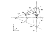
- FIG. 4 is a perspective view of the duct body.
- FIG. 5 shows the flow velocity distribution viewed from the stern side.
- FIG. 6 shows the relationship between the angle in the circumferential direction around the propeller axis and the flow direction angle.
- FIG. 7 is a front view of the duct device.
- FIG. 8 shows a cross-sectional shape of the duct body.
- FIG. 9 is a perspective view of the duct body.
- FIG. 10 is a front view of the duct body.
- FIG. 11 shows the duct body and water flow in the BB ′ cross section of FIG.
- FIG. 12 shows the duct body and water flow in the CC ′ cross section of FIG.
- FIG. 13 is a front view of the duct device.
- FIG. 14 shows the
- FIG. 3 is a side view showing a stern part of a ship provided with the duct device according to the first embodiment of the present invention.
- a propeller 3 is installed on the stern portion 2 of the ship 1 and a rudder 4 is installed on the rear side (stern side).
- the propeller 3 includes a plurality of wings arranged in the circumferential direction, and rotates about a rotation axis C1 that extends in a ship length direction that generally connects the bow and stern.
- a duct device 5 is attached in front of the propeller 3 in the stern part 2.
- the duct device 5 has an arcuate front edge 6 and a rear edge 7 that draw an arc with the rotation axis C ⁇ b> 1 inside.
- the contour shape of the trailing edge 7 in the cross section perpendicular to the rotation axis C ⁇ b> 1 is smaller than the radius of the leading edge 6.
- the contour shape of the trailing edge 6 is within a region of 0.2R to 0.5R from the rotation axis C in a cross section perpendicular to the rotation axis C1.
- FIG. 4 shows a schematic shape of the duct main body 9 having a function of changing the water flow in the duct device 5.
- the shape of the truncated cone is formed by the surface connecting the circle C3, the circle C4, and the C3 and C4 of the cone C2.
- the outline of the duct body 9 is shown by cutting out a region within a predetermined angle ⁇ with the rotation axis C1 as the center from the vertical line V around the rotation axis C1.
- the duct body 9 is symmetrical with respect to a circular straight line on a vertical plane including the rotation axis C1 of the propeller 3.
- the leading edge 6 of the duct body 9 draws an arc on a circle C4.
- the angle is ⁇ from the vertical line V to the left and right around the rotation axis C1.
- ⁇ is not particularly limited, it is desirable that ⁇ be 90 degrees or less because the water flow flowing into the upper half of the propeller 3 can easily obtain the propulsive force by the duct device 5.
- the rear edge 7 of the duct body 9 draws an arc on a circle C3.
- the angle of the arc is the same as that of the leading edge 6, but may be an angle different from that of the leading edge 6.
- the leading edge 6 and the trailing edge 7 do not have to be complete arcs, and may be arcs obtained by deforming arcs such as a parabolic shape, such as a convex shape.
- FIG. 5 shows a view of the flow velocity distribution of the water flowing into the propeller 3 as viewed from the rear (stern direction).
- FIG. 6 shows the distribution of the flow direction angle ⁇ at each circumferential angle ⁇ 1.
- the radial component of the flow velocity is small.
- the radial component of the flow velocity is large.
- the duct body 9 generates a larger propulsive force in a region where the radial component of the flow velocity is large. Therefore, it is desirable that the duct body 9 is formed so that the front edge 6 supplements the water flow in a region within an angle of 45 degrees from the vertical line V.
- FIG. 7 is a front view showing the duct device 5 as seen from the bow direction.
- FIG. 4 is a view of the inside of the duct body 9 viewed from the front in the AA ′ cross section shown in FIG. 3.
- the duct device 5 includes a support portion 10, and the duct body 9 is fixed to, for example, the bossing 8 of the stern portion 2 by the support portion 10.
- the radius of the trailing edge 7 is r1 and the radius of the rotating surface C5 of the propeller 3 is R, 0.2R ⁇ r1 ⁇ 0.5R.
- the entire trailing edge 7 is within a circle of 0.5R or less centered on the rotation axis C1.
- FIG. 8 shows a cross-sectional shape of the duct body 9.
- the cross section perpendicular to the circumferential direction of the duct body 9 has a wing shape at an arbitrary angle in the circumferential direction.
- the inner peripheral side of the duct body 9, that is, the side facing the rotation axis C1 is a negative pressure surface, and the outer peripheral side is a positive pressure surface.
- a propulsive force (a component in the bow direction of the combined force of lift and drag) is generated in the duct body 9 by the water flow.
- the propulsion efficiency of the propeller 3 in the region of r1 ⁇ 0.5R is relatively small from the beginning, so that a reduction in propulsive force of the propeller 3 can be suppressed to a small level.
- 9 and 10 are a perspective view and a front view showing a schematic shape of the duct main body 9a in the present embodiment.
- the duct body 9a has a shape with a greater inclination toward the top. As described below, according to such a shape, an efficient propulsive force can be obtained according to the flow velocity distribution of the stern portion 2.
- the cross section B by the plane P including the rotation axis C1 of the duct body 9 has the same blade shape as the cross section of the duct body 9 shown in FIG.
- the angle ⁇ formed by the chord line CH of the cross section and the extending direction (x-axis direction) of the rotation axis C1 is larger as the circumferential angle ⁇ 1 about the rotation axis C1 is closer to the vertical line V.
- the duct main body 9a has a front edge 7a that forms a part of the front edge side circle C3, similarly to the duct main body 9 in the first embodiment.
- the rear edge 6a of the duct main body 9a has a contour shifted from the rear edge side circle C4. That is, the smaller the angle ⁇ 1, the larger the shape of the rear edge side circle C4.
- Such a shape can be realized, for example, by forming the trailing edge 6a as a parabola.
- FIG. 11 shows the duct body 9a and the water flow in the BB ′ cross section of FIG.
- FIG. 12 shows the duct main body 9a and the water flow in the CC ′ section of FIG.
- the inclination angle of the duct body 9a (more precisely, the inclination angle in the plane including the rotation axis C1 with respect to the extending direction of the rotation axis C1 (x-axis direction)) ⁇ 1 is large.
- the water flow just above the rotation axis C1 flows into the rear edge 6a of the duct body 9a. Since the water flow in this region has a large component in the radial direction, the duct body 9a can generate a larger propulsive force when the duct body 9a has a large inclination.
- the inclination angle of the duct body 9a (more precisely, the inclination angle in the plane including the rotation axis C1 with respect to the extending direction of the rotation axis C1) ⁇ 2 is small.
- the water flow in this region has a larger component in the direction of the rotation axis C1 than the section BB ′. Therefore, the duct body 9a can generate a larger propulsive force because the inclination of the duct body 9a with respect to the direction of the rotation axis C1 is small.
- the shape of the duct body 9a is designed as follows. (1) The flow velocity distribution of the water flow ahead of the propeller 3 in the stern part 2 is obtained. (2) Based on the flow velocity distribution, the inclination of the duct body 9a in each circumferential direction ( ⁇ 1 in FIG. 11, ⁇ 2 in FIG. 12) approaches 0 to 20 degrees so that the angle of attack ( ⁇ 1 in FIG. 11 and ⁇ 2 in FIG. 12) approaches 0 degrees to 20 degrees. Design ⁇ 1, ⁇ 2).
- shapes other than the duct body 9a in FIG. 9 are also conceivable.
- a modified example in which the shape of the leading edge 6a is an arc and the shape of the trailing edge 7a is a curve (for example, a parabola) whose height is lower than the trailing edge side circle C3 as ⁇ 1 is smaller is conceivable. Even with such a shape, since the inclination of the duct body 9a is larger in the region where ⁇ 1 is smaller, a high propulsive force can be obtained according to the flow velocity distribution.
- FIG. 13 is a front view of the duct device 5a according to the third embodiment of the present invention.
- the duct device 5a in the present embodiment includes the same duct body 9a as in the second embodiment. Instead of this, the same duct body 9 as in the first embodiment may be used.
- the duct device 5a according to the third embodiment further includes reaction fins 12 including at least one blade (two blades in the example of FIG. 13). The reaction fin 12 improves the efficiency of the propeller 3 by giving the flow velocity distribution in the stern portion 2 a change in the direction opposite to the rotation direction of the propeller 3.
- FIG. 14 shows an example.
- the cross section of the reaction fin 12 attached to the right side as viewed from the stern direction is shown in the clockwise propeller 3 (providing forward thrust to the hull 1 when rotating clockwise when viewed from the stern direction).
- reaction fin 12 is attached to the front of the propeller 3 with a downward inclination angle theta R toward the bow direction.
- the negative pressure surface 12a is disposed in the rotation direction of the propeller 3, that is, in the clockwise rotation direction with respect to the positive pressure surface 12b.
- Such reaction fins 12 can improve the efficiency of the propeller 3.
- the reaction fin 12 is supported by the duct main body 9a at the end of the base (the side close to the rotation axis C1).
- the tip extends, for example, to 1.1R, where R is the radius of the rotating surface C5 of the propeller 3.
- the reaction fin 12 is most effective in the vicinity of the radius 0.7R where the efficiency of the propeller 3 is high. On the other hand, the effect is small near the radius of 0.5 R or less, and the efficiency of the propeller 3 may be lowered. In the present embodiment, the reaction fin 12 is not disposed near the base near the propeller 3 by being supported by the duct main body 9a, and can be disposed only in a region having a radius of 0.5 or more with the highest effect. Become.
- reaction fins 12 In a known reaction fin supported by bossing or the like, a configuration in which the effect on the water flow is reduced by twisting the angle of the fin near the base where the effect is low is also conceivable.
- the reaction fins 12 since the reaction fins 12 do not need to be arranged near the roots, the reaction fins 12 can be formed of members having a shape that is easy to process without twisting.
Abstract
This duct device is installed anterior to a propeller at the stern of a ship. The duct device is equipped with a duct body. The duct body has: a rear edge which is positioned on the posterior side of the ship, forms an arc around the rotary shaft of the propeller, and has a contour which falls within a range of 0.5R, wherein R represents the radius of the propeller, in a perpendicular direction to the rotary shaft; and a front edge which is positioned on the anterior side of the ship, forms an arc around the rotary shaft, and has a larger contour than the rear edge in a perpendicular direction to the rotary shaft. Thus, a decline in the propulsion efficiency of the propeller is prevented in the technology for installing the duct anterior to the propeller.
Description
本発明は、船舶の船尾部において、プロペラに流入する水流に影響を与えるダクト装置に関する。
The present invention relates to a duct device that affects a water flow flowing into a propeller at a stern portion of a ship.
船舶の推進効率を向上するためのデバイスとして、プロペラの前方にダクトを配置する技術が知られている。特許文献1は、そのような技術の一例を示す。
As a device for improving the propulsion efficiency of a ship, a technique for arranging a duct in front of a propeller is known. Patent document 1 shows an example of such a technique.
図1に、参考技術として、プロペラ前方に配置するダクトの一例を示す。船舶101の船尾部102にプロペラ103が配置され、プロペラ103の後方に舵104が配置される。プロペラ103の前方(船首方向)に、ダクト105が配置される。ダクト105は、概ねプロペラ103の回転軸を中心とする円環形状を有する。ダクト105の船首方向の端部は、船尾方向の端部よりも径が大きい。
Fig. 1 shows an example of a duct arranged in front of the propeller as a reference technique. A propeller 103 is disposed on the stern portion 102 of the ship 101, and a rudder 104 is disposed behind the propeller 103. A duct 105 is disposed in front of the propeller 103 (in the bow direction). The duct 105 has an annular shape that is generally centered on the rotation axis of the propeller 103. The end of the duct 105 in the bow direction has a larger diameter than the end in the stern direction.
図2は、図1の領域106におけるダクト105の拡大図である。ダクト105の周方向に垂直な断面は、翼形状を有する。翼の前縁が船首側、後縁が船尾側に配置される。ダクト105の内周側、すなわちプロペラの回転軸に近い側が負圧面107であり、外周側が正圧面108である。ダクト105は、翼形状の前縁と後縁とを結ぶ翼弦線がプロペラ103の回転軸に対して角度θをなして船尾側に向かって内周側に傾くように形成される。
FIG. 2 is an enlarged view of the duct 105 in the region 106 of FIG. A cross section perpendicular to the circumferential direction of the duct 105 has a wing shape. The leading edge of the wing is located on the bow side and the trailing edge is located on the stern side. The inner peripheral side of the duct 105, that is, the side close to the rotation axis of the propeller is the negative pressure surface 107, and the outer peripheral side is the positive pressure surface 108. The duct 105 is formed so that a chord line connecting the leading edge and the trailing edge of the wing shape is inclined toward the inner periphery side toward the stern side at an angle θ with respect to the rotation axis of the propeller 103.
図2において、プロペラ103の回転軸に対して角度Ψ=α+θで船尾部102における水流がダクト105に流入する。αは、翼断面形状を有するダクト105に対する水流の迎角である。この水流により、ダクト105が流れに垂直な揚力f101と、流れに平行な抗力f102とを発生する。揚力f101と抗力f102の合力f103の船首方向の成分が、ダクト105に働く推進力となる。
In FIG. 2, the water flow in the stern portion 102 flows into the duct 105 at an angle Ψ = α + θ with respect to the rotation axis of the propeller 103. α is the angle of attack of the water flow with respect to the duct 105 having the blade cross-sectional shape. By this water flow, the duct 105 generates a lift f101 perpendicular to the flow and a drag f102 parallel to the flow. A component in the bow direction of the resultant force f103 of the lift force f101 and the drag force f102 becomes a propulsive force that acts on the duct 105.
このようにダクト105は推進力を生み出すことができる。しかしながら、ダクト105はプロペラ103に流入する水流の向きを変え、見かけ上軸方向に加速する効果を持つ。プロペラ103は、水流の速度が遅い方が効率が高いため、ダクト105によってプロペラ103の軸方向に水流が加速されると、プロペラ103の効率が落ちる可能性がある。従って、ダクト105の追加によって、プロペラ103とダクト105とを合わせた全体の効率が有効に向上しない可能性がある。
Thus, the duct 105 can generate a propulsive force. However, the duct 105 has the effect of changing the direction of the water flow flowing into the propeller 103 and apparently accelerating in the axial direction. Since the propeller 103 is more efficient when the water flow speed is slower, if the water flow is accelerated in the axial direction of the propeller 103 by the duct 105, the efficiency of the propeller 103 may be reduced. Therefore, the addition of the duct 105 may not effectively improve the overall efficiency of the combined propeller 103 and duct 105.
プロペラの前方にダクトを設ける技術において、プロペラの推進効率の低下を避けることが望まれる。
In the technology of providing a duct in front of the propeller, it is desirable to avoid a decrease in propeller propulsion efficiency.
本発明の一実施形態において、ダクト装置は、船舶の船尾部においてプロペラの前方に配置される。ダクト装置は、ダクト本体を備える。ダクト本体は、船舶の後方側に位置し、プロペラの軸を内側とする弧を描き、軸方向に見た輪郭形状がプロペラの半径をRとして0.5R以下の領域に収まる後縁と、船舶の前方側に位置し、プロペラの軸を内側とする弧を描き、軸の方向に見た輪郭形状が前縁よりも大きい前縁とを有する。
In one embodiment of the present invention, the duct device is disposed in front of the propeller at the stern portion of the ship. The duct device includes a duct body. The duct body is located on the rear side of the ship, draws an arc with the propeller axis inside, and the contour shape seen in the axial direction is within the region of 0.5R or less with the propeller radius being R, An arc that is located on the front side of the propeller and has an axis that is the inner side of the axis of the propeller is drawn, and has a front edge that has a contour shape that is larger than the front edge.
本発明により、プロペラの前方にダクトを設ける技術において、プロペラの推進効率の低下を避けることが可能となる。
According to the present invention, in the technique of providing a duct in front of the propeller, it becomes possible to avoid a decrease in propulsion efficiency of the propeller.
以下、添付図面を参照して、本発明の実施形態を説明する。図3は、本発明の第1実施形態におけるダクト装置を備えた船舶の船尾部を示す側面図である。船舶1の船尾部2にプロペラ3が設置され、その後側(船尾側)に舵4が設置される。プロペラ3は、周方向に並ぶ複数の翼を備え、概ね船首と船尾を結ぶ船長方向に延長する回転軸C1を中心に回転する。
Hereinafter, embodiments of the present invention will be described with reference to the accompanying drawings. FIG. 3 is a side view showing a stern part of a ship provided with the duct device according to the first embodiment of the present invention. A propeller 3 is installed on the stern portion 2 of the ship 1 and a rudder 4 is installed on the rear side (stern side). The propeller 3 includes a plurality of wings arranged in the circumferential direction, and rotates about a rotation axis C1 that extends in a ship length direction that generally connects the bow and stern.
船尾部2におけるプロペラ3の前方に、ダクト装置5が取り付けられる。ダクト装置5は、回転軸C1を内側とする弧を描く円弧状の前縁6と後縁7とを有する。回転軸C1に垂直な断面における後縁7の輪郭形状は、前縁6の半径よりも小さい。プロペラ3の回転面の半径をRとすると、後縁6の輪郭形状は、回転軸C1に垂直な断面において回転軸Cから0.2R以上0.5R以下の領域に収まる。
A duct device 5 is attached in front of the propeller 3 in the stern part 2. The duct device 5 has an arcuate front edge 6 and a rear edge 7 that draw an arc with the rotation axis C <b> 1 inside. The contour shape of the trailing edge 7 in the cross section perpendicular to the rotation axis C <b> 1 is smaller than the radius of the leading edge 6. Assuming that the radius of the rotation surface of the propeller 3 is R, the contour shape of the trailing edge 6 is within a region of 0.2R to 0.5R from the rotation axis C in a cross section perpendicular to the rotation axis C1.
図4は、ダクト装置5において水流を変化させる機能を有するダクト本体9の概略形状を示す。プロペラ3の回転軸C1を中心として、所定の点(x=x0)を頂点とし、x軸方向に中心線を有する仮想的な円錐形C2を描く。その円錐形C2について、頂点から第1の距離x=x1におけるyz断面を円C3として示し、第2の距離x=x2(x2>x1)におけるyz断面を円C4として示す。
FIG. 4 shows a schematic shape of the duct main body 9 having a function of changing the water flow in the duct device 5. A virtual cone C2 having a predetermined point (x = x0) as a vertex and a center line in the x-axis direction is drawn with the rotation axis C1 of the propeller 3 as the center. For the cone C2, the yz cross section at the first distance x = x1 from the apex is shown as a circle C3, and the yz cross section at the second distance x = x2 (x2> x1) is shown as a circle C4.
円C3と、円C4と、円錐C2のうちC3とC4とを結ぶ表面によって、円錐台の形状が形成される。この円錐台のうち、回転軸C1を中心として、鉛直線Vから左右それぞれに、回転軸C1を中心として所定の角度φ以内の領域を切り取った箇所が、ダクト本体9の概略形状を示す。ダクト本体9は、プロペラ3の回転軸C1を含む鉛直面において、円直線に関して左右対称である。
The shape of the truncated cone is formed by the surface connecting the circle C3, the circle C4, and the C3 and C4 of the cone C2. In this truncated cone, the outline of the duct body 9 is shown by cutting out a region within a predetermined angle φ with the rotation axis C1 as the center from the vertical line V around the rotation axis C1. The duct body 9 is symmetrical with respect to a circular straight line on a vertical plane including the rotation axis C1 of the propeller 3.
ダクト本体9の前縁6は円C4上の円弧を描く。その角度は、回転軸C1を中心として鉛直線Vから左右にそれぞれφである。φの値は特に限定されないが、プロペラ3の上半分に流入する水流の方がダクト装置5による推進力を得やすいため、φは90度以下であることが望ましい。ダクト本体9の後縁7は円C3上の円弧を描く。図4の例では、その円弧の角度は、前縁6と同じであるが、前縁6と異なる角度でもよい。前縁6と後縁7は、完全な円弧である必要は無く、例えば放物線など、上に凸の形状のように円弧を変形した弧であってもよい。
The leading edge 6 of the duct body 9 draws an arc on a circle C4. The angle is φ from the vertical line V to the left and right around the rotation axis C1. Although the value of φ is not particularly limited, it is desirable that φ be 90 degrees or less because the water flow flowing into the upper half of the propeller 3 can easily obtain the propulsive force by the duct device 5. The rear edge 7 of the duct body 9 draws an arc on a circle C3. In the example of FIG. 4, the angle of the arc is the same as that of the leading edge 6, but may be an angle different from that of the leading edge 6. The leading edge 6 and the trailing edge 7 do not have to be complete arcs, and may be arcs obtained by deforming arcs such as a parabolic shape, such as a convex shape.
図5に、プロペラ3に流入する水流の流速分布を後方(船尾方向)から見た図を示す。図6に、各周方向角度φ1における流向角Ψの分布を示す。この例で示されるように、回転軸C1より上側で鉛直線Vから角度が45度以上の領域11においては、流速の半径方向の成分が小さい。それに対して、鉛直線Vからの角度が45度以下の領域においては、流速の半径方向の成分が大きい。ダクト本体9は、流速の半径方向の成分が大きい領域において、より大きい推進力を生成する。従って、ダクト本体9は、その前縁6が、鉛直線Vからの角度45度以内の領域における水流を補足するように形成することが望ましい。
FIG. 5 shows a view of the flow velocity distribution of the water flowing into the propeller 3 as viewed from the rear (stern direction). FIG. 6 shows the distribution of the flow direction angle Ψ at each circumferential angle φ1. As shown in this example, in the region 11 above the rotation axis C1 and having an angle of 45 degrees or more from the vertical line V, the radial component of the flow velocity is small. On the other hand, in the region where the angle from the vertical line V is 45 degrees or less, the radial component of the flow velocity is large. The duct body 9 generates a larger propulsive force in a region where the radial component of the flow velocity is large. Therefore, it is desirable that the duct body 9 is formed so that the front edge 6 supplements the water flow in a region within an angle of 45 degrees from the vertical line V.
よって、例えば前縁6がφ=45度の扇形、又は45度の位置における水流を確実に補足するためにφ=50度の扇形を有するダクト本体9であれば、十分に推進力を発生することができる。従って、好ましい実施形態において、ダクト本体9は、プロペラ3の回転軸C1を通る鉛直線Vを中心とした周方向の角度が50度以内に収まる。更に、φ=50度以内に設定されると、ダクト本体9が小さいため軽量であり、且つその外側の領域においてプロペラ3に流入する流れを妨げないため好ましい。
Therefore, for example, if the leading edge 6 has a fan shape of φ = 45 degrees or a duct body 9 having a fan shape of φ = 50 degrees in order to reliably supplement the water flow at a position of 45 degrees, sufficient thrust is generated. be able to. Therefore, in a preferred embodiment, the duct body 9 has an angle in the circumferential direction centered on the vertical line V passing through the rotation axis C1 of the propeller 3 within 50 degrees. Furthermore, it is preferable that φ is set within 50 degrees because the duct body 9 is small and light, and the flow flowing into the propeller 3 is not hindered in the outer region.
図7は、船首方向から見たダクト装置5を示す前面図である。図3に示すA-A´断面において、ダクト本体9の内側を前方から覗き込んだ図である。ダクト装置5は支持部10を備え、ダクト本体9は、支持部10によって船尾部2の例えばボッシング8に固定される。
FIG. 7 is a front view showing the duct device 5 as seen from the bow direction. FIG. 4 is a view of the inside of the duct body 9 viewed from the front in the AA ′ cross section shown in FIG. 3. The duct device 5 includes a support portion 10, and the duct body 9 is fixed to, for example, the bossing 8 of the stern portion 2 by the support portion 10.
後縁7の半径をr1とし、プロペラ3の回転面C5の半径をRとしたとき、0.2R≦r1≦0.5Rである。後縁7が完全な円弧でない場合は、後縁7の全体が回転軸C1を中心とする0.5R以下の円内に収まることが好ましい。以下に、このような半径r1によって得られる利点を説明する。
When the radius of the trailing edge 7 is r1 and the radius of the rotating surface C5 of the propeller 3 is R, 0.2R ≦ r1 ≦ 0.5R. When the trailing edge 7 is not a complete arc, it is preferable that the entire trailing edge 7 is within a circle of 0.5R or less centered on the rotation axis C1. Hereinafter, advantages obtained by such a radius r1 will be described.
図8に、ダクト本体9の断面形状が示されている。ダクト本体9の周方向に垂直な断面は、周方向の任意の角度において翼形状を有する。ダクト本体9の内周側、すなわち回転軸C1に向く側が負圧面であり、外周側が正圧面である。
FIG. 8 shows a cross-sectional shape of the duct body 9. The cross section perpendicular to the circumferential direction of the duct body 9 has a wing shape at an arbitrary angle in the circumferential direction. The inner peripheral side of the duct body 9, that is, the side facing the rotation axis C1 is a negative pressure surface, and the outer peripheral side is a positive pressure surface.
船舶1が前方に航行しているとき、船体に相対的に水流が発生する。船尾部2において、ダクト装置5の位置における水流が、ダクト本体9によって変化する。ダクト本体9の内側において、水流がダクト本体9によって回転軸C1の方向に曲げられ、軸方向の流速が速い水流f1となる。一方、一般的には、プロペラ3の上側における水流は、軸方向の流速が遅い。ダクト本体9の外側には、このような軸方向の流速が遅い水流f2が流入する。
When the ship 1 is sailing forward, water flow is relatively generated in the hull. In the stern part 2, the water flow at the position of the duct device 5 is changed by the duct body 9. Inside the duct main body 9, the water flow is bent in the direction of the rotation axis C <b> 1 by the duct main body 9, and becomes a water flow f <b> 1 having a high axial flow velocity. On the other hand, generally, the water flow on the upper side of the propeller 3 has a low axial flow velocity. A water flow f2 having such a slow axial flow velocity flows into the outside of the duct body 9.
一般的なプロペラ3が最も効率的に仕事を行うのは、半径方向の中心よりやや外側、例えば0.7R付近の領域である。本実施形態においては、この領域においては、軸方向の流速の遅い水流f2が流入するため、プロペラ3が高い効率で推進力を生成する。
It is a region slightly outside the center in the radial direction, for example, in the vicinity of 0.7R, that the general propeller 3 performs the work most efficiently. In this embodiment, in this region, since the water flow f2 having a slow axial flow rate flows in, the propeller 3 generates a propulsive force with high efficiency.
一方、ダクト本体9よりも内側の領域では、水流によってダクト本体9に推進力(揚力と抗力の合力の船首方向の成分)が発生する。ダクト本体9によって、水流f1の軸方向の流速が上昇するが、r1≦0.5Rの領域におけるプロペラ3の推進効率はもともと比較的小さいため、プロペラ3の推進力低下は小さく抑えられる。ダクト本体9によって有効な推進力を得るためには、r1≧0.2Rであることが望ましい。
On the other hand, in the region inside the duct body 9, a propulsive force (a component in the bow direction of the combined force of lift and drag) is generated in the duct body 9 by the water flow. Although the axial flow velocity of the water flow f1 is increased by the duct body 9, the propulsion efficiency of the propeller 3 in the region of r1 ≦ 0.5R is relatively small from the beginning, so that a reduction in propulsive force of the propeller 3 can be suppressed to a small level. In order to obtain an effective driving force by the duct body 9, it is desirable that r1 ≧ 0.2R.
以上に説明したように、本実施形態においては、軸からの半径方向の距離をrとした場合、r=0.7R程度の領域ではダクト装置5が流れを妨げずにプロペラ3が高い推進力を発生し、プロペラ3の効率が小さいR≦0.5の領域ではダクト装置5によって推進力を発生することができる。そのため、プロペラ3とダクト装置5とを合わせて高い推進力を得ることができる。
As described above, in the present embodiment, when the distance in the radial direction from the shaft is r, the propeller 3 has a high propulsive force without disturbing the flow of the duct device 5 in the region of r = 0.7R. In the region where R ≦ 0.5 where the efficiency of the propeller 3 is small, propulsive force can be generated by the duct device 5. Therefore, high propulsive force can be obtained by combining the propeller 3 and the duct device 5.
次に、本発明の第2実施形態について説明する。図9、図10は、本実施形態におけるダクト本体9aの概略形状を示す斜視図と前面図である。第1実施形態におけるダクト本体9が円錐面の一部を形成していたのに対して、本実施形態においては、ダクト本体9aが、上方ほど傾きが大きい形状を有している。以下に説明するように、このような形状により、船尾部2の流速分布に応じて、効率的な推進力を得ることができる。
Next, a second embodiment of the present invention will be described. 9 and 10 are a perspective view and a front view showing a schematic shape of the duct main body 9a in the present embodiment. In contrast to the duct body 9 in the first embodiment forming part of the conical surface, in this embodiment, the duct body 9a has a shape with a greater inclination toward the top. As described below, according to such a shape, an efficient propulsive force can be obtained according to the flow velocity distribution of the stern portion 2.
本実施形態におけるダクト本体9aの形状についてより詳細に説明すると、ダクト本体9の回転軸C1を含む平面Pによる断面Bは、図8に示したダクト本体9の断面と同様の翼形状を有する。その断面の翼弦線CHと、回転軸C1の延長方向(x軸方向)とがなす角度θは、回転軸C1を中心とする周方向の角度φ1が鉛直線Vに近い位置ほど大きい。
Describing in more detail about the shape of the duct body 9a in the present embodiment, the cross section B by the plane P including the rotation axis C1 of the duct body 9 has the same blade shape as the cross section of the duct body 9 shown in FIG. The angle θ formed by the chord line CH of the cross section and the extending direction (x-axis direction) of the rotation axis C1 is larger as the circumferential angle φ1 about the rotation axis C1 is closer to the vertical line V.
図9、図10においては、ダクト本体9aは、第1実施形態におけるダクト本体9と同様に、前縁側円C3の一部を形成する前縁7aを有する。一方、ダクト本体9aの後縁6aは、後縁側円C4からずれた輪郭を有する。すなわち、角度φ1が小さいほど、後縁側円C4よりもより大きく上方に張り出した形状を有する。このような形状は、例えば後縁6aを放物線に形成することによって実現できる。
9 and 10, the duct main body 9a has a front edge 7a that forms a part of the front edge side circle C3, similarly to the duct main body 9 in the first embodiment. On the other hand, the rear edge 6a of the duct main body 9a has a contour shifted from the rear edge side circle C4. That is, the smaller the angle φ1, the larger the shape of the rear edge side circle C4. Such a shape can be realized, for example, by forming the trailing edge 6a as a parabola.
図11は、図10のB-B´断面におけるダクト本体9aと水流を示す。図12は、図10のC-C´断面におけるダクト本体9aと水流を示す。図11に示すB-B´断面においては、ダクト本体9aの傾き角(正確には、回転軸C1の延長方向(x軸方向)に対する、回転軸C1を含む平面内の傾き角)θ1が大きい。この領域には、回転軸C1に対して真上付近の水流がダクト本体9aの後縁6aに流入する。この領域における水流は半径方向に大きい成分を有するため、ダクト本体9aが大きい傾きを有することにより、ダクト本体9aがより大きな推進力を発生することができる。
FIG. 11 shows the duct body 9a and the water flow in the BB ′ cross section of FIG. FIG. 12 shows the duct main body 9a and the water flow in the CC ′ section of FIG. In the BB ′ cross section shown in FIG. 11, the inclination angle of the duct body 9a (more precisely, the inclination angle in the plane including the rotation axis C1 with respect to the extending direction of the rotation axis C1 (x-axis direction)) θ1 is large. . In this region, the water flow just above the rotation axis C1 flows into the rear edge 6a of the duct body 9a. Since the water flow in this region has a large component in the radial direction, the duct body 9a can generate a larger propulsive force when the duct body 9a has a large inclination.
一方、図12に示すC-C´断面においては、ダクト本体9aの傾き角(正確には、回転軸C1の延長方向に対する、回転軸C1を含む平面内における傾き角)θ2が小さい。この領域の水流は、B-B´断面に比べて回転軸C1方向の成分が大きい。そのため、ダクト本体9aの回転軸C1方向に対する傾きが小さいことにより、ダクト本体9aがより大きな推進力を発生することができる。
On the other hand, in the CC ′ section shown in FIG. 12, the inclination angle of the duct body 9a (more precisely, the inclination angle in the plane including the rotation axis C1 with respect to the extending direction of the rotation axis C1) θ2 is small. The water flow in this region has a larger component in the direction of the rotation axis C1 than the section BB ′. Therefore, the duct body 9a can generate a larger propulsive force because the inclination of the duct body 9a with respect to the direction of the rotation axis C1 is small.
典型的な翼形状を有するダクトにおいては、ダクト本体9aに流入する水流の迎角αが0度~20度付近で大きな推進力が得られる。従って、ダクト本体9aの形状は、以下のように設計される。(1)船尾部2のプロペラ3前方の水流の流速分布を求める。(2)その流速分布に基づいて、各周方向の角度における迎角(図11のα1、図12のα2)が0度~20度に近づくように、各周方向におけるダクト本体9aの傾き(θ1、θ2)を設計する。
In a duct having a typical wing shape, a large propulsive force can be obtained when the angle of attack α of the water flow flowing into the duct body 9a is around 0 to 20 degrees. Accordingly, the shape of the duct body 9a is designed as follows. (1) The flow velocity distribution of the water flow ahead of the propeller 3 in the stern part 2 is obtained. (2) Based on the flow velocity distribution, the inclination of the duct body 9a in each circumferential direction (α1 in FIG. 11, α2 in FIG. 12) approaches 0 to 20 degrees so that the angle of attack (α1 in FIG. 11 and α2 in FIG. 12) approaches 0 degrees to 20 degrees. Design θ1, θ2).
本実施形態においては、図9のダクト本体9a以外の形状も考えられる。例えば、前縁6aの形状を円弧とし、後縁7aの形状を、φ1が小さいほど後縁側円C3よりも高さが低い曲線(例えば放物線)とする変形例も考えられる。このような形状によっても、φ1が小さい領域ほどダクト本体9aの傾きが大きいため、流速分布に応じて、高い推進力を得ることができる。
In the present embodiment, shapes other than the duct body 9a in FIG. 9 are also conceivable. For example, a modified example in which the shape of the leading edge 6a is an arc and the shape of the trailing edge 7a is a curve (for example, a parabola) whose height is lower than the trailing edge side circle C3 as φ1 is smaller is conceivable. Even with such a shape, since the inclination of the duct body 9a is larger in the region where φ1 is smaller, a high propulsive force can be obtained according to the flow velocity distribution.
図13は、本発明の第3実施形態におけるダクト装置5aの前面図である。本実施形態におけるダクト装置5aは、第2実施形態と同じダクト本体9aを備える。これに替えて、第1実施形態と同じダクト本体9を用いてもよい。第3実施形態におけるダクト装置5aは更に、少なくとも1枚のブレード(図13の例では2枚のブレード)からなるリアクションフィン12を備える。リアクションフィン12は、船尾部2における流速分布に対して、プロペラ3の回転方向とは逆方向の変化を与えることによって、プロペラ3の効率を向上する。
FIG. 13 is a front view of the duct device 5a according to the third embodiment of the present invention. The duct device 5a in the present embodiment includes the same duct body 9a as in the second embodiment. Instead of this, the same duct body 9 as in the first embodiment may be used. The duct device 5a according to the third embodiment further includes reaction fins 12 including at least one blade (two blades in the example of FIG. 13). The reaction fin 12 improves the efficiency of the propeller 3 by giving the flow velocity distribution in the stern portion 2 a change in the direction opposite to the rotation direction of the propeller 3.
リアクションフィン12の輪郭形状、及び取付角度については、公知のリアクションフィンの設計を適用することができる。図14は、その一例を示す。右回りの(船尾方向から見て時計回りに回転するときに船体1に前方向きの推進力を与える)プロペラ3において、船尾方向から見て右側に取り付けられるリアクションフィン12の断面を示す。この位置において、リアクションフィン12は船首方向に向かって下向きの傾き角θRでプロペラ3の前方に取り付けられる。その負圧面12aは、正圧面12bに対して、プロペラ3の回転方向、すなわち時計周りの回転の進行方向に配置される。このようなリアクションフィン12により、プロペラ3の効率を向上することができる。
For the contour shape and the mounting angle of the reaction fin 12, a known reaction fin design can be applied. FIG. 14 shows an example. The cross section of the reaction fin 12 attached to the right side as viewed from the stern direction is shown in the clockwise propeller 3 (providing forward thrust to the hull 1 when rotating clockwise when viewed from the stern direction). In this position, reaction fin 12 is attached to the front of the propeller 3 with a downward inclination angle theta R toward the bow direction. The negative pressure surface 12a is disposed in the rotation direction of the propeller 3, that is, in the clockwise rotation direction with respect to the positive pressure surface 12b. Such reaction fins 12 can improve the efficiency of the propeller 3.
図13においては、リアクションフィン12が、その根元(回転軸C1に近い側)の端部において、ダクト本体9aによって支持されている。その先端は、プロペラ3の回転面C5の半径をRとして、例えば1.1Rまで延長する。
In FIG. 13, the reaction fin 12 is supported by the duct main body 9a at the end of the base (the side close to the rotation axis C1). The tip extends, for example, to 1.1R, where R is the radius of the rotating surface C5 of the propeller 3.
リアクションフィン12は、プロペラ3の効率が高い半径0.7R付近で最も効果を発揮する。それに対して、半径0.5R以下の付近では効果が小さく、逆にプロペラ3の効率を下げる場合もある。本実施形態においては、ダクト本体9aによって支持することによって、リアクションフィン12をプロペラ3に近い根元付近には配置せず、効果が最も高い半径0.5以上の領域にのみ配置することが可能となる。
The reaction fin 12 is most effective in the vicinity of the radius 0.7R where the efficiency of the propeller 3 is high. On the other hand, the effect is small near the radius of 0.5 R or less, and the efficiency of the propeller 3 may be lowered. In the present embodiment, the reaction fin 12 is not disposed near the base near the propeller 3 by being supported by the duct main body 9a, and can be disposed only in a region having a radius of 0.5 or more with the highest effect. Become.
ボッシング等によって支持される公知のリアクションフィンにおいては、効果の低い根元付近においてフィンの角度に捩じりを加えて、水流への影響を低減するという構成も考えられる。しかしながら、本実施形態においては、根元付近にリアクションフィン12を配置する必要が無いため、捩じりが無く加工が容易な形状の部材によってリアクションフィン12を形成することができる。
In a known reaction fin supported by bossing or the like, a configuration in which the effect on the water flow is reduced by twisting the angle of the fin near the base where the effect is low is also conceivable. However, in the present embodiment, since the reaction fins 12 do not need to be arranged near the roots, the reaction fins 12 can be formed of members having a shape that is easy to process without twisting.
以上、本発明の実施形態を詳述してきたが、実際には、上記の実施形態に限られるものではなく、本発明の要旨を逸脱しない範囲の変更があっても本発明に含まれる。
The embodiments of the present invention have been described in detail above. However, actually, the present invention is not limited to the above-described embodiments, and modifications within a scope not departing from the gist of the present invention are included in the present invention.
Claims (10)
- 船体の船尾部においてプロペラの前方に配置され、後縁と前記後縁より前方にある前縁とを有するダクト本体を具備し、
前記後縁は、前記プロペラの回転軸と直交する第1直交面内で前記回転軸より離れて弧状の輪郭形状を有し、前記プロペラの半径をRとして前記後縁の前記輪郭形状が前記プロペラの前記回転軸から0.5R以下の領域に収まり、
前記前縁は、前記プロペラの回転軸と直交する第2直交面内で前記回転軸より離れて弧状の輪郭形状を有し、前記前縁の前記輪郭形状が、前記プロペラの前記回転軸から前記後縁の前記輪郭形状よりも大きい距離を有する
ダクト装置。 A duct body disposed in front of the propeller at the stern of the hull, having a rear edge and a front edge forward of the rear edge;
The trailing edge has an arcuate contour shape in a first orthogonal plane perpendicular to the rotation axis of the propeller and is separated from the rotation axis, and the contour shape of the trailing edge is defined by the radius of the propeller being R. Within the region of 0.5R or less from the rotation axis of
The front edge has an arcuate contour shape away from the rotation axis in a second orthogonal plane orthogonal to the rotation axis of the propeller, and the contour shape of the front edge is separated from the rotation axis of the propeller. A duct device having a distance larger than the contour shape of the trailing edge. - 前記回転軸を含む平面における前記ダクト本体の断面は、前記回転軸の側を負圧面とする翼形状を有する
請求項1に記載のダクト装置。 The duct device according to claim 1, wherein a cross section of the duct main body in a plane including the rotation shaft has a blade shape having a suction surface on the rotation shaft side. - 前記ダクト本体は、上向きの鉛直線からの前記回転軸の周方向の角度が50度以内に収まる
請求項1に記載のダクト装置。 The duct device according to claim 1, wherein the duct body has an angle in a circumferential direction of the rotating shaft from an upward vertical line within 50 degrees. - 前記ダクト本体の前記回転軸を含む平面による断面は翼形状を有し、
前記断面の翼弦線と、前記回転軸の延長方向とがなす角度は、前記回転軸を中心とする周方向の角度が鉛直線に近い位置ほど大きい
請求項1に記載のダクト装置。 A cross-section by a plane including the rotation axis of the duct body has a wing shape,
The duct device according to claim 1, wherein an angle formed by the chord line of the cross section and an extending direction of the rotation shaft is larger as a circumferential angle around the rotation shaft is closer to a vertical line. - 前記ダクト本体に支持され、前記ダクト本体から半径方向外側に向かって延長する少なくとも1枚のリアクションフィンを更に具備する
請求項1から4のいずれかに記載のダクト装置。 The duct device according to any one of claims 1 to 4, further comprising at least one reaction fin supported by the duct body and extending radially outward from the duct body. - 船体と、
プロペラと、
前記船体の船尾部において前記プロペラの前方に配置されるダクト装置と
を具備し、
前記ダクト装置は、弧状の輪郭形状を有し、後縁と前記後縁より前方にある前縁とを有するダクト本体を具備し、
前記後縁は、前記プロペラの回転軸と直交する第1直交面内で前記回転軸より離れて弧状の輪郭形状を有し、前記プロペラの半径をRとして前記後縁の前記輪郭形状が前記プロペラの前記回転軸から0.5R以下の領域に収まり、
前記前縁は、前記プロペラの回転軸と直交する第2直交面内で前記回転軸より離れて弧状の輪郭形状を有し、前記前縁の前記輪郭形状が、前記プロペラの前記回転軸から前記後縁の前記輪郭形状よりも大きい距離を有する
船舶。 The hull,
With a propeller,
A duct device disposed in front of the propeller at the stern portion of the hull,
The duct device has an arcuate contour, and includes a duct body having a rear edge and a front edge forward of the rear edge,
The trailing edge has an arcuate contour shape in a first orthogonal plane perpendicular to the rotation axis of the propeller and is separated from the rotation axis, and the contour shape of the trailing edge is defined by the radius of the propeller being R. Within the region of 0.5R or less from the rotation axis of
The front edge has an arcuate contour shape away from the rotation axis in a second orthogonal plane orthogonal to the rotation axis of the propeller, and the contour shape of the front edge is separated from the rotation axis of the propeller. A ship having a distance larger than the contour shape of the trailing edge. - 前記回転軸を含む平面における前記ダクト本体の断面は、前記回転軸の側を負圧面とする翼形状を有する
請求項6に記載の船舶。 The ship according to claim 6, wherein a cross section of the duct main body in a plane including the rotation shaft has a wing shape with a suction surface on the rotation shaft side. - 前記ダクト本体は、上向きの鉛直線からの前記回転軸の周方向の角度が50度以内に収まる
請求項6に記載の船舶。 The marine vessel according to claim 6, wherein the duct body has an angle in a circumferential direction of the rotating shaft from an upward vertical line within 50 degrees. - 前記ダクト本体の前記回転軸を含む平面による断面は翼形状を有し、
前記断面の翼弦線と、前記回転軸の延長方向とがなす角度は、前記回転軸を中心とする周方向の角度が鉛直線に近い位置ほど大きい
請求項6に記載の船舶。 A cross-section by a plane including the rotation axis of the duct body has a wing shape,
The ship according to claim 6, wherein an angle formed by the chord line of the cross section and an extending direction of the rotation shaft is larger as a circumferential angle around the rotation shaft is closer to a vertical line. - 前記ダクト本体に支持され、前記ダクト本体から半径方向外側に向かって延長する少なくとも1枚のリアクションフィンを更に具備する
請求項6から9のいずれかに記載の船舶。 The ship according to any one of claims 6 to 9, further comprising at least one reaction fin supported by the duct main body and extending radially outward from the duct main body.
Priority Applications (3)
| Application Number | Priority Date | Filing Date | Title |
|---|---|---|---|
| CN201380067884.6A CN104884347B (en) | 2012-12-27 | 2013-12-26 | Plumbing installation and the ship using the plumbing installation |
| KR1020157016571A KR20150088836A (en) | 2012-12-27 | 2013-12-26 | Duct device and ship utilizing same |
| KR1020177018814A KR20170084346A (en) | 2012-12-27 | 2013-12-26 | Duct device and ship utilizing same |
Applications Claiming Priority (2)
| Application Number | Priority Date | Filing Date | Title |
|---|---|---|---|
| JP2012286009A JP5901512B2 (en) | 2012-12-27 | 2012-12-27 | Duct device and ship using the same |
| JP2012-286009 | 2012-12-27 |
Publications (1)
| Publication Number | Publication Date |
|---|---|
| WO2014104167A1 true WO2014104167A1 (en) | 2014-07-03 |
Family
ID=51021243
Family Applications (1)
| Application Number | Title | Priority Date | Filing Date |
|---|---|---|---|
| PCT/JP2013/084812 WO2014104167A1 (en) | 2012-12-27 | 2013-12-26 | Duct device and ship utilizing same |
Country Status (4)
| Country | Link |
|---|---|
| JP (1) | JP5901512B2 (en) |
| KR (2) | KR20170084346A (en) |
| CN (1) | CN104884347B (en) |
| WO (1) | WO2014104167A1 (en) |
Cited By (1)
| Publication number | Priority date | Publication date | Assignee | Title |
|---|---|---|---|---|
| CN107428403A (en) * | 2015-03-31 | 2017-12-01 | 三井造船株式会社 | Ship |
Families Citing this family (3)
| Publication number | Priority date | Publication date | Assignee | Title |
|---|---|---|---|---|
| JP6478228B2 (en) * | 2016-12-05 | 2019-03-06 | 国立研究開発法人 海上・港湾・航空技術研究所 | Stern shape and ship with stern duct and fins |
| JP6655562B2 (en) | 2017-01-27 | 2020-02-26 | 三菱重工業株式会社 | Duct equipment and ships |
| JP6758210B2 (en) | 2017-01-31 | 2020-09-23 | 三菱重工業株式会社 | Duct equipment and ships |
Citations (5)
| Publication number | Priority date | Publication date | Assignee | Title |
|---|---|---|---|---|
| JPH0450238Y2 (en) * | 1985-08-28 | 1992-11-26 | ||
| JP2008137462A (en) * | 2006-11-30 | 2008-06-19 | Ihi Marine United Inc | Duct device for ship |
| JP2011178222A (en) * | 2010-02-26 | 2011-09-15 | Ihi Corp | Ship |
| KR20120068222A (en) * | 2010-12-17 | 2012-06-27 | 현대중공업 주식회사 | Duct structure for ship |
| KR20120124205A (en) * | 2011-05-03 | 2012-11-13 | 에스피피조선 주식회사 | Fuel-efficiecy Improving crown duct for ship |
Family Cites Families (2)
| Publication number | Priority date | Publication date | Assignee | Title |
|---|---|---|---|---|
| DE202008006069U1 (en) * | 2008-03-10 | 2008-07-17 | Becker Marine Systems Gmbh & Co. Kg | Device for reducing the power requirement of a ship |
| KR20100127854A (en) * | 2008-10-20 | 2010-12-06 | 미츠비시 쥬고교 가부시키가이샤 | Twin skeg ship |
-
2012
- 2012-12-27 JP JP2012286009A patent/JP5901512B2/en active Active
-
2013
- 2013-12-26 CN CN201380067884.6A patent/CN104884347B/en active Active
- 2013-12-26 WO PCT/JP2013/084812 patent/WO2014104167A1/en active Application Filing
- 2013-12-26 KR KR1020177018814A patent/KR20170084346A/en not_active Application Discontinuation
- 2013-12-26 KR KR1020157016571A patent/KR20150088836A/en active Application Filing
Patent Citations (5)
| Publication number | Priority date | Publication date | Assignee | Title |
|---|---|---|---|---|
| JPH0450238Y2 (en) * | 1985-08-28 | 1992-11-26 | ||
| JP2008137462A (en) * | 2006-11-30 | 2008-06-19 | Ihi Marine United Inc | Duct device for ship |
| JP2011178222A (en) * | 2010-02-26 | 2011-09-15 | Ihi Corp | Ship |
| KR20120068222A (en) * | 2010-12-17 | 2012-06-27 | 현대중공업 주식회사 | Duct structure for ship |
| KR20120124205A (en) * | 2011-05-03 | 2012-11-13 | 에스피피조선 주식회사 | Fuel-efficiecy Improving crown duct for ship |
Cited By (1)
| Publication number | Priority date | Publication date | Assignee | Title |
|---|---|---|---|---|
| CN107428403A (en) * | 2015-03-31 | 2017-12-01 | 三井造船株式会社 | Ship |
Also Published As
| Publication number | Publication date |
|---|---|
| JP5901512B2 (en) | 2016-04-13 |
| KR20150088836A (en) | 2015-08-03 |
| KR20170084346A (en) | 2017-07-19 |
| JP2014125200A (en) | 2014-07-07 |
| CN104884347A (en) | 2015-09-02 |
| CN104884347B (en) | 2018-01-09 |
Similar Documents
| Publication | Publication Date | Title |
|---|---|---|
| DK2100809T3 (en) | Device for reducing a ship's engine power requirements | |
| EP3085966B1 (en) | Axial flow fan | |
| JP5230852B1 (en) | Small ducted propeller and ship | |
| WO2014104167A1 (en) | Duct device and ship utilizing same | |
| WO2010046961A1 (en) | Twin skeg ship | |
| EP2952427A1 (en) | Stern structure of ship | |
| KR20110083998A (en) | Duct for ship | |
| JP6021678B2 (en) | Duct device and ship using the same | |
| JP6422020B2 (en) | Twin skeg ship | |
| WO2011102103A1 (en) | Thruster with duct attached and vessel comprising same | |
| WO2015098665A1 (en) | Duct device | |
| JP2009051283A (en) | Turbine fin with duct | |
| JP2010116007A (en) | Propeller of marine vessel | |
| WO2018025644A1 (en) | Ship | |
| WO2021014919A1 (en) | Stern fin | |
| KR20180075183A (en) | Duct apparatus of thruster for vessel | |
| WO2018139138A1 (en) | Duct device and ship | |
| KR101556438B1 (en) | Device for reducing the power demand for the propulsion of a ship | |
| KR101764400B1 (en) | Duct apparatus for ship with twist type stator | |
| JP6380848B2 (en) | Ship | |
| JP2014156185A (en) | Propeller back stream rectifier | |
| KR20240013002A (en) | Marine accelerating propeller | |
| JP2004114743A (en) | Vessel | |
| JP2014156200A (en) | Fin device and ship | |
| JP2019006169A (en) | Marine propulsion device and ship equipped with the same |
Legal Events
| Date | Code | Title | Description |
|---|---|---|---|
| 121 | Ep: the epo has been informed by wipo that ep was designated in this application |
Ref document number: 13869283 Country of ref document: EP Kind code of ref document: A1 |
|
| ENP | Entry into the national phase |
Ref document number: 20157016571 Country of ref document: KR Kind code of ref document: A |
|
| NENP | Non-entry into the national phase |
Ref country code: DE |
|
| 122 | Ep: pct application non-entry in european phase |
Ref document number: 13869283 Country of ref document: EP Kind code of ref document: A1 |