WO2014104140A1 - 超音波接合装置及び端子と電線の接合構造 - Google Patents
超音波接合装置及び端子と電線の接合構造 Download PDFInfo
- Publication number
- WO2014104140A1 WO2014104140A1 PCT/JP2013/084760 JP2013084760W WO2014104140A1 WO 2014104140 A1 WO2014104140 A1 WO 2014104140A1 JP 2013084760 W JP2013084760 W JP 2013084760W WO 2014104140 A1 WO2014104140 A1 WO 2014104140A1
- Authority
- WO
- WIPO (PCT)
- Prior art keywords
- wire
- terminal
- core wire
- anvil
- joint portion
- Prior art date
- Legal status (The legal status is an assumption and is not a legal conclusion. Google has not performed a legal analysis and makes no representation as to the accuracy of the status listed.)
- Ceased
Links
Images







Classifications
-
- H—ELECTRICITY
- H01—ELECTRIC ELEMENTS
- H01R—ELECTRICALLY-CONDUCTIVE CONNECTIONS; STRUCTURAL ASSOCIATIONS OF A PLURALITY OF MUTUALLY-INSULATED ELECTRICAL CONNECTING ELEMENTS; COUPLING DEVICES; CURRENT COLLECTORS
- H01R4/00—Electrically-conductive connections between two or more conductive members in direct contact, i.e. touching one another; Means for effecting or maintaining such contact; Electrically-conductive connections having two or more spaced connecting locations for conductors and using contact members penetrating insulation
- H01R4/02—Soldered or welded connections
- H01R4/023—Soldered or welded connections between cables or wires and terminals
-
- H—ELECTRICITY
- H01—ELECTRIC ELEMENTS
- H01R—ELECTRICALLY-CONDUCTIVE CONNECTIONS; STRUCTURAL ASSOCIATIONS OF A PLURALITY OF MUTUALLY-INSULATED ELECTRICAL CONNECTING ELEMENTS; COUPLING DEVICES; CURRENT COLLECTORS
- H01R4/00—Electrically-conductive connections between two or more conductive members in direct contact, i.e. touching one another; Means for effecting or maintaining such contact; Electrically-conductive connections having two or more spaced connecting locations for conductors and using contact members penetrating insulation
- H01R4/02—Soldered or welded connections
- H01R4/029—Welded connections
-
- H—ELECTRICITY
- H01—ELECTRIC ELEMENTS
- H01R—ELECTRICALLY-CONDUCTIVE CONNECTIONS; STRUCTURAL ASSOCIATIONS OF A PLURALITY OF MUTUALLY-INSULATED ELECTRICAL CONNECTING ELEMENTS; COUPLING DEVICES; CURRENT COLLECTORS
- H01R43/00—Apparatus or processes specially adapted for manufacturing, assembling, maintaining, or repairing of line connectors or current collectors or for joining electric conductors
- H01R43/02—Apparatus or processes specially adapted for manufacturing, assembling, maintaining, or repairing of line connectors or current collectors or for joining electric conductors for soldered or welded connections
- H01R43/0207—Ultrasonic-, H.F.-, cold- or impact welding
Definitions
- the present invention relates to an ultrasonic bonding apparatus for bonding a terminal and an electric wire by ultrasonic bonding, and a terminal-electric wire bonding structure in which the terminal and the electric wire are bonded by ultrasonic bonding.
- an ultrasonic bonding apparatus including an ultrasonic horn that applies ultrasonic vibration to a core wire is used.
- the terminal 301 When joining a terminal and an electric wire using this type of ultrasonic welding apparatus, first, the terminal 301 is placed on the upper surface 311 of the anvil 310 as shown in FIG. In this case, since the terminal 301 generally has a mating terminal connection portion 302 for connecting to the mating terminal at the front portion and a wire joining portion 303 for joining the electric wire at the rear portion thereof, the wire joining portion. Only 303 is placed on the upper surface 311 of the anvil 310. Then, the core wire Wa that is exposed by removing the insulation coating Wb at the end of the electric wire W is placed on the electric wire joint portion 303 placed on the anvil 310.
- the core wire Wa on the wire joint portion 303 is pressed by the pressing surface 321 on the lower surface of the ultrasonic horn 320, and the core wire Wa and the wire joint portion 303 are connected to the anvil 310. While being sandwiched, ultrasonic vibration is applied from the ultrasonic horn 320. By doing so, frictional heat due to ultrasonic vibration is generated between the strands constituting the core wire Wa, the contact surface between the core wire Wa and the wire joint portion 303, or the like. As a result, all the strands are finally deformed by thermal softening, and the core wire Wa and the wire joint portion 303 are joined while the core wire Wa is integrated.
- the wire connecting portion 313 of the terminal 312 is formed in a curved shape so that the end portion in the width direction is located above the intermediate portion, and the upper surface of the anvil 340 is adjusted accordingly.
- 341 is formed in a curved shape, and the pressing surface 332 in contact with the core wire Wa of the ultrasonic horn 330 is formed in a semi-cylindrical surface in accordance with the shape of the inner surface 313a in contact with the core wire Wa of the electric wire connection portion 313.
- the core wire Wa is ultrasonically welded to the wire connection portion 313 a plurality of times while changing the relative position between the terminal 312 and the terminal 312 (see Patent Document 1).
- the bonding energy may be scraped off and good bonding may not be possible.
- both end portions in the width direction of the wire joint portion 303 placed on the anvil 310 are pressed against the anvil 310 by the pressing step portion 354 of the terminal pressing member 350. It is considered to apply ultrasonic vibration by the ultrasonic horn 320 in a state.
- the opposing regulating walls 356 of the terminal pressing member 350 play a role of preventing protrusion when the core wire Wa is deformed on the flat wire joining portion 303.
- connection part 302 may be adversely affected.
- the mating terminal connecting portion 302 is a rectangular tube-shaped box portion that accepts a male terminal that is a mating terminal
- an elastic contact piece (such as a leaf spring) that elastically holds the male terminal inside the box portion.
- an engagement location and a welding location may exist in the surrounding wall of a box part. Such a portion may cause damage due to resonance of the box portion due to propagation of vibration, which may deteriorate the yield of the ultrasonically bonded product.
- the present invention has been made in view of the above-described circumstances, and the object thereof is to prevent resonance of the mating terminal connection portion, eliminate the adverse effects thereof, and improve the quality of the ultrasonically bonded product.
- An object of the present invention is to provide an ultrasonic bonding apparatus and a terminal-wire bonding structure manufactured by the ultrasonic bonding apparatus.
- an ultrasonic bonding apparatus is characterized by the following (1) to (3).
- Anvil to be placed on, Ultrasonic vibration is applied to the core wire and the contact portion between the core wire and the wire joint portion while pressing the core wire placed on the wire joint portion placed on the upper surface of the anvil from above.
- an ultrasonic horn for joining the wire joint and the core wire
- a terminal pressing member that presses the wire joint against the upper surface of the anvil
- An ultrasonic bonding apparatus comprising: The terminal holding member is A first pressing portion that presses both ends in the width direction orthogonal to the front-rear direction of the wire joint portion against the anvil, and the mating terminal connection on the front side of the portion of the wire joint portion to which the core wire is joined.
- a second pressing portion that presses a portion connected to the portion against the anvil.
- the upper surface of the anvil is a flat surface that is in close contact with the lower surface of the wire joint,
- the outer surfaces are opposed to each other, and an ultrasonic wave is applied to join the wire joint and the core wire.
- the pressing surface in contact with the core wire of the ultrasonic horn is formed as a flat surface or a concave curved surface recessed upward with respect to the flat surface, Inclined surfaces that incline toward the upper outside in the width direction are provided at both ends in the width direction of the pressing surface.
- the terminal holding member is When the first pressing portion presses both ends in the width direction of the wire joint portion placed on the upper surface of the anvil, which are connected to the upper side of each first pressing portion, the electric wire It has a regulating wall that faces across the space above the joint, Irregularities are provided along the vertical direction on the wall surface of each regulation wall.
- the second pressing portion of the terminal pressing member has an anvil portion connected to the mating terminal connecting portion on the front side of the portion where the core wire is bonded in the electric wire bonding portion. Therefore, the vibration at the time of applying the ultrasonic vibration is difficult to propagate to the mating terminal connecting portion that is in front of the pressed portion. As a result, it is possible to eliminate an adverse effect due to resonance of the mating terminal connection portion, and it is possible to improve the yield and quality of products joined by ultrasonic joining.
- the ultrasonic bonding apparatus having the above configuration (2), since the inclined surfaces for securing the escape space of the core wire are provided at both ends in the width direction of the ultrasonic horn, the ultrasonic wave is ultrasonically bonded.
- the height of the burr can be reduced by making the shape of the burr when the core wire escapes into the minute gap between the outer surface of the horn and the regulating wall to generate a burr instead of a sharp shape. Therefore, the burr becomes inconspicuous, and the area where the ultrasonic horn and the burr are rubbed during ultrasonic bonding (contact area between the ultrasonic horn and the burr) can be reduced. Can be prevented.
- the core wire of the electric wire is ultrasonically bonded to the electric wire bonding portion while the electric wire bonding portion of the terminal is pressed against the anvil by the first pressing portion of the terminal pressing member.
- the deformation range of the core wire can be regulated by the regulating wall of the terminal pressing member. Therefore, the core wire does not protrude laterally from the electric wire joint.
- the heat-softened core wire may come into close contact with the regulation wall, so-called sticking may occur, but the wall surface of the regulation wall is provided with unevenness to reduce adhesion, so that it adheres strongly. There is nothing wrong. Therefore, the transition to the next terminal joining process is performed smoothly.
- the terminal-wire joining structure according to the present invention is characterized by the following (4) or (5).
- (4) For the wire joint portion of the terminal having a mating terminal connection portion for connecting to the mating terminal at the front portion and having a wire joining portion for joining the core wire of the end of the electric wire continuously to the rear portion.
- Both end portions in the width direction orthogonal to the front-rear direction of the wire joint portion are located on the outer side in the width direction than both side surfaces of the joint portion of the core wire joined to the wire joint portion, On both side surfaces of the joint portion of the core wire, irregularities are provided along the height direction of the joint portion, thing.
- the pressing space of the pressing portion of the terminal pressing member is secured at both ends in the width direction orthogonal to the front-rear direction of the electric wire bonding portion of the terminal.
- the unevenness formed by the unevenness provided on the regulation wall is provided on both side surfaces of the joint portion of the core wire with respect to the wire joint portion, the rigidity against bending along the height direction of the joint portion is increased, and the core wire The quality of the joint can be improved.
- the ultrasonic bonding apparatus is characterized by the following (6) and (7).
- the wire connecting portion in the terminal having a mating terminal connecting portion for connecting to the mating terminal in the front portion and having a wire joining portion in the rear portion for joining to the core wire of the end of the electric wire is placed on the upper surface.
- Anvil and A contact portion that is disposed above the anvil and presses the core wire placed on the wire joint portion placed on the upper surface of the anvil from above, and the core wire and the wire joint portion are in contact with each other.
- An ultrasonic bonding apparatus comprising: The terminal holding member is A pressing portion that presses against both ends of the width direction orthogonal to the front-rear direction of the wire joint portion against the anvil; A space above the electric wire joint when the pressing portion presses both ends in the width direction of the electric wire joint placed on the upper surface of the anvil, which are connected to the upper side of the respective press. And a regulating wall facing each other, Have Irregularities are provided along the vertical direction on the wall surface of each regulation wall. (7) In the ultrasonic bonding apparatus according to (6) above, The unevenness extends with a constant cross section in the vertical direction, thing.
- the core wire of the electric wire is ultrasonically applied to the electric wire bonding portion while the electric wire bonding portion of the terminal is pressed against the anvil by the pressing portion of the terminal pressing member.
- the deformation range of the core wire can be regulated by the regulating wall of the terminal pressing member. Therefore, the core wire does not protrude laterally from the electric wire joint.
- the heat-softened core wire may come into close contact with the regulation wall, so-called sticking may occur, but the wall surface of the regulation wall is provided with unevenness to reduce adhesion, so that it adheres strongly. There is nothing wrong. Therefore, the transition to the next terminal joining process is performed smoothly.
- the contact area between the core wire before ultrasonic bonding and the regulating wall decreases, the pressing force with which the ultrasonic horn presses the core wire, the vibration frequency with which the ultrasonic horn vibrates, or the amplitude with which the ultrasonic horn vibrates Even if a large energy is applied to the core wire by setting such as a relatively large numerical value, the core wire can be prevented from being damaged.
- the junction structure of the terminal and the electric wire according to the present invention is characterized by the following (8).
- the core wire has ultrasonic waves at the wire joint portion in the terminal having a mating terminal connection portion for connecting to the mating terminal in the front portion and a wire joining portion in the rear portion for joining to the core wire of the end of the electric wire.
- Both end portions in the width direction orthogonal to the front-rear direction of the wire joint portion are located on the outer side in the width direction than both side surfaces of the joint portion of the core wire joined to the wire joint portion, On both side surfaces of the joint portion of the core wire, irregularities are provided along the height direction of the joint portion, A junction structure of a terminal and an electric wire characterized by that.
- the pressing space of the pressing portion of the terminal pressing member is secured at both ends in the width direction orthogonal to the front-rear direction of the electric wire bonding portion of the terminal.
- the wire bonding portion can be reliably pressed against the anvil.
- the unevenness formed by the unevenness provided on the regulation wall is provided on both side surfaces of the joint portion of the core wire with respect to the wire joint portion, the rigidity against bending along the height direction of the joint portion is increased, and the core wire The quality of the joint can be improved.
- the present invention it is possible to eliminate the adverse effects due to resonance of the mating terminal connection portion, and to improve the yield and quality of the ultrasonically bonded product.
- the present invention it is possible to prevent the core wire of the electric wire from adhering to the terminal pressing member when ultrasonic bonding is performed while pressing the terminal against the anvil by the terminal pressing member. Therefore, the transition to the next joining process can be performed smoothly.
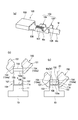
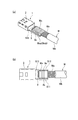
- FIG. 1 is a perspective view showing a schematic configuration of a main part of an ultrasonic bonding apparatus according to an embodiment of the present invention.
- FIG. 2 is a perspective view showing a configuration of a terminal pressing member that is a component in the ultrasonic bonding apparatus according to the embodiment of the present invention.
- FIG. 3A to FIG. 3C are diagrams showing the configuration of a terminal pressing member that is a component in the ultrasonic bonding apparatus according to the embodiment of the present invention, and FIG. FIG. 3B is a side view partially showing a cross section, and FIG. 3C is an enlarged view taken along the arrow IIIc in FIG.
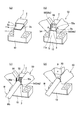
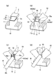
- FIG. 4 (a) to 4 (d) are process explanatory views when a terminal and an electric wire are bonded using the ultrasonic bonding apparatus according to one embodiment of the present invention.
- FIG. 4 (a) is on the anvil.
- the figure which shows the state which mounted the electric wire junction part of the terminal is a figure which shows the state which presses the electric wire junction part of a terminal with respect to an anvil with a terminal pressing member
- FIG.4 (c) is a figure of electric wire.
- FIG.4 (d) is providing ultrasonic vibration, pushing down an ultrasonic horn and pressing a core wire against an electric wire junction part with an ultrasonic horn.
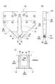
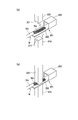
- FIG. 5 (a) and 5 (b) are diagrams showing the state at the time of the process shown in FIG. 4 (b), and FIG. 5 (a) shows the portion where the terminal is pressed by the terminal pressing member.
- FIG. 5B is a front view showing a state where the terminal is pressed by the terminal pressing member.
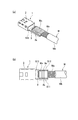
- 6 (a) and 6 (b) are diagrams showing a product (joining structure) in which a terminal and an electric wire are joined by the ultrasonic joining apparatus of one embodiment of the present invention, and FIG. 6 (a) is a perspective view.
- FIG. 6B is a plan view seen from above.
- FIG. 7A to FIG. 7C are explanatory diagrams of another embodiment of the present invention, and FIG.
- FIG. 7A shows a product (joint structure) in which a terminal and an electric wire are joined by the apparatus of this embodiment.
- 7 (b) and 7 (c) are process explanatory diagrams in the middle of manufacturing the product, and
- FIG. 7 (b) is a terminal presser for pressing the terminal placed on the anvil against the anvil.
- FIG. 7C is a front view showing a state in which the terminal is pressed by the terminal pressing member.
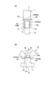
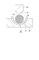
- FIG. 8 is an explanatory diagram of still another embodiment of the present invention, and is a cross-sectional view showing a state in which an ultrasonic horn is about to ultrasonically bond a core wire to an electric wire bonding portion.
- 9 (a) and 9 (b) are diagrams for explaining the effect of the embodiment of FIG. 8, and FIG.
- FIG. 9 (a) shows the variability when ultrasonic bonding is performed by the apparatus of the embodiment of FIG.
- FIG. 9B is a cross-sectional view showing a comparative example.
- 10 (a) and 10 (b) are explanatory diagrams of a conventional example
- FIG. 10 (a) is a perspective view showing a state where a terminal and a core wire are sandwiched between an anvil and an ultrasonic horn
- FIG. 10 (b) is sandwiched. It is a perspective view which shows a mode that ultrasonic bonding is performed in a state.
- FIG. 11 is an explanatory diagram of another conventional example.
- FIG. 12 is a cross-sectional view seen from the front showing a state in which the terminal wire pressing portion is pressed against the anvil during ultrasonic bonding.
- FIG. 13 is a perspective view showing a schematic configuration of a main part of an ultrasonic bonding apparatus according to an embodiment of the present invention.
- FIG. 14 is a perspective view showing a configuration of a terminal pressing member which is a component in the ultrasonic bonding apparatus.
- 15 (a) to 15 (c) are views showing the structure of the terminal holding member, FIG. 15 (a) is a front view, FIG. 15 (b) is a side view showing a part in section, and FIG. (C) is the IIIc arrow enlarged view of Fig.15 (a).
- FIG. 16 (a) to 16 (c) are process explanatory diagrams in the case where the terminal and the electric wire are bonded using the ultrasonic bonding apparatus, and FIG. 16 (a) shows the electric wire bonding portion of the terminal on the anvil.
- FIG. 16 (b) is a diagram showing a state where the terminal is pressed
- FIG. 16 (c) is a diagram showing a state where the terminal wire connecting portion is pressed against the anvil by the terminal pressing member
- FIG. FIG. 16D is a diagram showing a state in which ultrasonic vibration is applied while the ultrasonic horn is lowered and the core wire is pressed against the electric wire joint by the ultrasonic horn. .
- FIG. 17 (a) and 17 (b) are diagrams showing the state at the time of the process shown in FIG. 16 (b), and FIG. 17 (a) shows the portion where the terminal is pressed by the terminal pressing member.
- FIG. 17B is a front view showing a state in which the terminal is pressed by the terminal pressing member.
- 18 (a) and 18 (b) are diagrams showing a product (joining structure) in which a terminal and an electric wire are joined by the ultrasonic joining apparatus, FIG. 18 (a) is a perspective view, and FIG. 18 (b) is a perspective view. It is the top view seen from the top.
- FIG. 1 is a perspective view showing a schematic configuration of a main part of an ultrasonic bonding apparatus according to an embodiment of the present invention
- FIG. 2 is a perspective view showing a configuration of a terminal pressing member which is a component of the apparatus
- FIG. 3 (c) is a configuration diagram of the terminal pressing member
- FIG. 3 (a) is a front view
- FIG. 3 (b) is a side view partially showing a cross-section
- FIG. 3 (c) is a diagram of FIG. 3 (a).
- FIG. 4 (d) are process explanatory diagrams in the case of joining a terminal and an electric wire using an ultrasonic bonding apparatus
- Fig. 5 (a) shows a step of holding a terminal by a terminal holding member
- FIG. 5B is a front view showing a state where the terminal is pressed by the terminal pressing member.
- the ultrasonic bonding apparatus includes an anvil 10 fixed in a fixed position, an ultrasonic horn 20 that is mounted on the anvil 10 so as to be movable up and down, and an ultrasonic horn 20.
- the terminal pressing member 50 is provided so as to be able to move up and down independently of the ultrasonic horn 20.
- the ultrasonic bonding apparatus includes an elevator mechanism for the ultrasonic horn 20, a vibration mechanism for imparting ultrasonic vibration to the ultrasonic horn 20, a lift mechanism for the terminal pressing member 50, and a transport mechanism for the terminal 1. And an electric wire W transport mechanism.
- the terminal-attached electric wire manufacturing apparatus including the ultrasonic bonding apparatus is provided with a mechanism for peeling off the insulation coating Wb at the end of the electric wire W to expose the core wire Wa.
- the terminal 1 is also called a rectangular tube-like mating terminal connecting portion (in the case of a general female terminal, a “box portion”) for connecting to the mating terminal at the front portion. ) 2, and the electric wire joint portion 3 for joining the core wire Wa of the end of the electric wire W continuously to the rear portion thereof.
- the wire joint portion 3 in this case is configured as a single flat plate and does not correspond to a bottom plate in a barrel-type wire joint portion having a U-shaped cross section as will be described later.
- the mating terminal connection portion (box portion) 2 is formed by bending a single plate material and engaging or welding the mating portion to form a rectangular tube shape, and has an elastic contact piece inside, The mating terminal is elastically sandwiched between the mating terminal connecting portion 2 and the inner surface of the peripheral wall, thereby making electrical contact with the mating terminal.
- the electric wire W is formed by sheathing a core wire Wa formed by twisting a large number of strands into a circular cross section with an insulating coating Wb made of synthetic resin, and the terminal insulating coating Wb is connected to the terminal 1.
- the core wire Wa is exposed by skinning over a predetermined length necessary for joining.
- the anvil 10 has a flat upper surface 11 a of a convex portion 11 having a width corresponding to the left-right width dimension of the electric wire joint portion 3 of the terminal 1, and a lower surface of the electric wire joint portion 3 of the terminal 1. It is a block-shaped member used as a mounting surface.
- the ultrasonic horn 20 is disposed so as to be movable up and down above the anvil 10, and the core wire Wa of the electric wire W placed on the electric wire joint portion 3 placed on the upper surface 11 a of the anvil 10 is pressed from above to the pressing surface 21 (lower surface). ), Ultrasonic vibration is applied to the core wire Wa and the contact portion between the core wire Wa and the wire joint portion 3 to join the wire joint portion 3 and the core wire Wa.
- the terminal pressing member 50 presses the wire joint portion 3 of the terminal 1 against the upper surface 11a of the anvil 10 when the ultrasonic horn 20 applies ultrasonic vibration to the core wire Wa. As shown to c), it is comprised as a thick plate-shaped member of the attitude
- This terminal pressing member 50 is equipped with a posture in which the plate thickness direction is directed in the front-rear direction of the terminal 1, and the shape of the lower half viewed from the plate thickness direction has a symmetrical shape that narrows toward the lower end. ing.
- a wide slit portion 52 starting from a position slightly lower than the upper end and extending to the lower end is provided at the center in the left-right width direction of the terminal presser member 50, and the slit portion 52 extending vertically extends below the terminal presser member 50.
- the half is divided into left and right legs 51. Further, as shown in FIG. 1, the ultrasonic horn 20 can be moved up and down so as not to touch the terminal pressing member 50 in the slit portion 52.
- a pressing step 54 is provided in the form.
- the pressing step portions 54 provided on the left and right leg portions 51 are arranged in the width direction (terminal 1 of the electric wire joint portion 3 of the terminal 1 placed on the upper surface 11a of the convex portion 11 of the anvil 10. This is a portion corresponding to a first pressing portion that presses against both ends 3a (see FIGS. 4A to 5B) of both ends 3a (refer to FIGS.
- These pressing step portions 54 are provided with pressing surfaces 54 a slightly applied to the upper surfaces of the left and right end portions of the wire joint portion 3.
- the width of the upper space of the wire joint portion 3 in the left-right direction is restricted to be smaller than the left-right width dimension of the wire joint portion 3, so that the core wire Wa is thermally softened along with ultrasonic vibration.
- a restricting wall 56 is provided for restricting the wire joint portion 3 from protruding beyond the width of the wire joint portion 3 when deformed.
- Each regulating wall 56 extends vertically upward from the inner end of the pressing surface 54 a of the pressing step 54.
- the regulation walls 56 are wall surfaces that may come into close contact while being pressed when the core wire Wa is deformed, the wall surfaces of the regulation walls 56 are easily peeled off even when the core wire Wa adheres.
- the unevenness 56a is provided.
- the irregularities 56a extend in the vertical direction with a constant cross section so that the core wire Wa is not caught when the terminal pressing member 50 is raised.
- a connecting bar 55 for connecting the left and right leg portions 51 is provided at the lower ends of the left and right leg portions 51.
- the connecting bar 55 is a portion corresponding to a second pressing portion that presses the portion connected to the mating terminal connecting portion 2 on the front side of the portion where the core wire Wa of the wire connecting portion 3 is bonded to the anvil 10.
- the lower end surface 55 a of the connecting bar 55 that presses against the upper surface of the wire joint portion 3 is formed as the same plane as the pressing surface 54 a of the pressing step portion 54.
- the terminal pressing member 50 incorporates a heater 60 for raising the temperature of the member 50.
- the heater 60 in this case is a rod-shaped cartridge type, and is inserted into holes 61 formed in both end surfaces of the terminal pressing member 50 in the left-right width direction.
- the terminal pressing member 50 is lowered.
- the pressing surface 54a of the pressing step portion (first pressing portion) 54 presses both end portions 3a in the width direction of the wire joint portion 3 downward as indicated by the arrow A, and the wire joint portion 3 against the anvil 10. Press down.
- the connecting bar (second pressing portion) 55 presses the portion connected to the mating terminal connecting portion 2 on the front side of the portion where the core wire Wa of the electric wire bonding portion 3 is bonded to the anvil 10. Hold down the wire joint 3.
- the terminal 1 is disconnected from the carrier 9 (see FIG. 1) connecting the terminals 1 in a chain.
- the terminal pressing member 50 presses the three locations S1, S2, and S3 on the upper surface of the wire joint portion 3 with the two pressing step portions 54 and the one connecting bar 55. To do.
- the core wire Wa of the terminal of the electric wire W is placed on the electric wire joint portion 3.
- the ultrasonic horn 20 is lowered thereon as indicated by arrow B, and the core wire placed on the wire joint portion 3 placed on the upper surface of the anvil 10. Wa is pressed by the pressing surface 21 from above, and ultrasonic vibration is applied to the core wire Wa by the ultrasonic horn 20 while applying a pressing force, and ultrasonic vibration is applied to the core wire Wa and the contact portion between the core wire Wa and the wire joint portion 3.
- the electric wire junction part 3 and the core wire Wa are joined.
- the ultrasonic horn 20 is first raised, then the terminal pressing member 50 is raised, the electric wire W joined to the terminal 1 is picked up from the anvil 10 and conveyed to the discharge section.
- the terminal and wire joining process is completed by the above process. The steps in this case are automatically performed in order, and this is performed one after another for each set of terminal 1 and electric wire W.
- the terminal pressing member 50 is connected to both ends in the width direction of the wire bonding portion 3 of the terminal 1 and the mating terminal connection portion 2 of the wire bonding portion 3. Is pressed against the anvil 10, the vibration followed by the wire joint portion 3 can be suppressed as small as possible.
- the connecting bar (second pressing portion) 55 of the terminal pressing member 50 presses the portion connected to the mating terminal connection portion 2 in the wire joint portion 3 against the anvil 10, so that the mating terminal connection portion Propagation of vibration to the two sides can be suppressed as much as possible. Therefore, it is possible to eliminate the adverse effects due to resonance of the counterpart terminal connection portion 2 and improve the yield and quality of products joined by ultrasonic joining.
- the connecting bar 55 on the front side of the core wire Wa of the terminal of the electric wire W, the front end of the core wire Wa can be positioned, and the quality of the finished product can be stabilized. Further, since the restriction wall 56 of the terminal pressing member 50 prevents the protrusion of the core wire Wa from being deformed, the quality of the finished product can be improved. In particular, since the irregularity 56a is provided on the wall surface of the regulation wall 56, even when the core wire Wa is thermally softened and deformed and is in close contact with the regulation wall 56, adhesion of the regulation wall 56 and the core wire Wa can be prevented. Work can proceed smoothly.
- the frictional heat from the joining target portion escapes to the terminal pressing member 50, so that the fixing force after joining may not increase.
- the heater 60 by raising the temperature of the terminal pressing member 50 by the heater 60, it is possible to prevent the escape of frictional heat from the joining target portion and contribute to an increase in the fixing force of the joining portion.
- the present invention can also be applied to the case where the wire joint portion 103 provided at the rear portion of the terminal 101 is configured as a barrel type having a U-shaped cross section.
- Another embodiment of the present invention will be described with reference to FIGS. 7 (a) to 7 (c).
- symbol is attached
- the wire joint portion 103 of the terminal 101 in this case has a core wire joint portion 104 and a covering crimp portion 105, and the core wire joint portion 104 and the cover crimp portion 105 are
- the common bottom plate 106 continuously extending from the mating terminal connecting portion 102 and the side plates 107 and 108 formed upright on both sides of the bottom plate 106 in the width direction are respectively configured.
- the ultrasonic bonding apparatus for bonding the electric wire W to the terminal 101 having the electric wire bonding portion 103 having such a shape ultrasonically transmits the core wire Wa of the electric wire W to the bottom plate 106 of the core wire bonding portion 104. It is comprised so that it may join.
- the terminal pressing member 150 moves along the left and right side surfaces of the convex portion 11 of the anvil 10 when the terminal pressing member 150 descends to the lower ends of the left and right leg portions 151.
- the side walls 107 are pressed against the upper ends of the left and right side plates 107 of the core wire joint portion 104 (corresponding to both end portions in the width direction orthogonal to the front-rear direction of the wire joint portion 103).
- the step part (first pressing part) 154 that presses the electric wire joint part 103 against the anvil 10 via the left and right leg parts 151 is connected, and the core wire Wa of the electric wire joint part 3 is joined.
- a connecting bar (second pressing portion) 155 that presses against the anvil 10 a portion on the bottom plate 106 connected to the mating terminal connecting portion 102 on the front side.
- the pressing step 154 protrudes inwardly from the guide wall 153 by a dimension applied to the upper end of the side plate 107 of the core wire joint 104, and the upper end of the side plate 107 can be pressed by a downward pressing surface 154a. Further, the lower surface 155a of the connecting bar 155 is provided so as to press against the upper surface of the bottom plate 106 at a position where the side plate 107 of the core wire joining portion 104 is interrupted.
- the core wire bonding portion 104 of the terminal 101 is connected to the convex portion 11 of the anvil 10 as shown in FIG. On the upper surface 11a.
- the terminal pressing member 150 is lowered. Then, the pressing surface 154 a of the pressing step portion (first pressing portion) 154 presses the upper ends of the side plates 107 at both ends in the width direction of the core wire joint portion 104 downward, and presses the core wire joint portion 104 against the anvil 10. .
- the connecting bar (second pressing portion) 155 presses the portion on the bottom plate 106 connected to the mating terminal connecting portion 102 on the front side of the portion where the core wire Wa of the wire joint portion 103 is joined downward, and the anvil. 10, the electric wire joint 103 is pressed against the surface.
- the core wire Wa of the end of the electric wire W is placed on the bottom plate 106 of the core wire joint 104.
- the ultrasonic horn 20 is lowered, and the core wire Wa placed on the bottom plate 106 of the core wire joint 104 placed on the upper surface of the anvil 10 is pressed from above, and ultrasonic waves are applied while applying a pressing force.
- the ultrasonic vibration is applied to the core wire Wa by the horn 20 and the ultrasonic vibration is applied to the contact portion between the core wire Wa and the core wire Wa and the core wire joint portion 104, thereby joining the core wire joint portion 104 and the core wire Wa.
- the terminal pressing member 150 causes the both ends in the width direction of the wire joint portion 103 of the terminal 101 and the portion on the bottom plate 106 connected to the mating terminal connection portion 102 of the wire joint portion 103 to the anvil 10. Since it is pressing against the vibration, the following vibration of the wire joint portion 103 can be suppressed as small as possible.
- the connecting bar (second pressing portion) 155 of the terminal pressing member 150 presses the portion connected to the mating terminal connection portion 102 of the wire joint portion 103 against the anvil 10, so that the mating terminal connection portion The propagation of vibration to the 102 side can be suppressed as much as possible. Therefore, it is possible to improve the yield and quality of a product joined by ultrasonic joining without adverse effects due to resonance of the counterpart terminal connection portion 102.
- the connecting bar 155 on the front side of the core wire Wa of the terminal of the electric wire W, the front end of the core wire Wa can be positioned, and the quality of the finished product can be stabilized.
- the core wire joining portion 104 of the terminal 101 is previously provided with the side plate 107 that restricts the protrusion of the core wire Wa when the core wire Wa is deformed, so that the quality of the finished product can be improved.
- FIG. 8 is an explanatory view of the embodiment, and is a cross-sectional view showing a state where the core wire is ultrasonically joined to the wire joint portion with the ultrasonic horn.
- the terminal 1 having the flat wire joint portion 3 shown in the embodiment of FIGS. 1 to 6B is adopted as a terminal to be joined.
- the terminal pressing member 50 employs the terminal pressing member 50 shown in the embodiment of FIGS. 1 to 6B.
- the upper surface 11 a of the convex portion 11 of the anvil 10 is a flat surface that is in close contact with the lower surface of the wire joint portion 3.
- the dimension in the width direction of the ultrasonic horn 20 is such that both the outer side surfaces in the width direction of the ultrasonic horn 20 are opposed to the both outer side surfaces, and an ultrasonic wave is applied to join the wire joint portion 3 and the core wire Wa.
- the dimension is set such that a minute gap ⁇ for assuring the operation of the ultrasonic horn 20 can be ensured between the restriction wall 56 that restricts the escape of the core wire Wa outward in the width direction.
- the pressing surface 21 in contact with the core wire of the ultrasonic horn 20 is formed as a flat surface or a concave curved surface 22 that is recessed upward with respect to the flat surface, and convex curved surfaces are formed at both ends of the pressing surface 21 in the width direction.
- An inclined surface 23 (for example, “R”) is provided.
- the inclined surfaces 23 at both ends of these pressing surfaces 21 are inclined upward in the width direction, and when the ultrasonic wave is applied to join the wire joining portion 3 and the core wire Wa, The escape space for the core wire Wa (particularly the element wire Wa1) that escapes to the minute gap ⁇ is ensured before the minute gap ⁇ , whereby the core line Wa (particularly the element wire Wa1) escapes into the minute gap ⁇ . It works to reduce the height of the burr.
- the bare wire Wa1 escapes into the minute gap ⁇ and hardly frays.
- the minute gap ⁇ 0.10 mm with respect to the diameter of the strand Wa1 being 0.26 mm.
- the amount of burrs popping out the height of burrs
- the rate at which the burrs break off due to rubbing with the ultrasonic horn 20 Becomes larger.
- the above-described inclined surfaces 23 are provided at both ends of the pressing surface 21 of the ultrasonic horn 20 so as to reduce burr pop-out (burr height).
- burr pop-out burr height
- the height from the upper surface of the electric wire junction part 3 to the point (horn end) where the inclined surface 23 of the ultrasonic horn 20 intersects the outer side surface is larger than the heights of both ends in the width direction of the core wire Wa at the start of bonding.
- FIG. 9 (a) and 9 (b) are diagrams for explaining the effect of the embodiment of FIG. 8, and FIG. 9 (a) shows the variability when ultrasonic bonding is performed by the apparatus of the embodiment of FIG.
- FIG. 9B is a cross-sectional view showing a comparative example.
- the size of the minute gap ⁇ between the outer wall of the ultrasonic horn 20 and the regulating wall 56 is constant.
- inclined surfaces 23 are formed at both ends of the pressing surface 21 of the ultrasonic horn 20, whereas in the comparative example shown in FIG. 9B, the pressing surface of the ultrasonic horn 20 is used.
- Inclined surfaces 23 are not formed at both ends of 21, and a concave curved surface 22 is continuously formed up to the horn end.
- the inclined surfaces 23 for securing the clearance space of the core wire Wa are provided at both ends in the width direction of the pressing surface 21 of the ultrasonic horn 20.
- the shape of the burr Br1 when the core wire Wa escapes into the minute gap ⁇ between the outer surface of the ultrasonic horn 20 and the regulating wall 56 and a burr is generated is not a sharp shape but a mountain shape.
- the height of the burr Br1 can be reduced. Therefore, the burr Br1 becomes inconspicuous, and the area (contact area between the ultrasonic horn and the burr) Sx1 between the ultrasonic horn 20 and the burr Br1 during ultrasonic bonding is reduced from the contact area Sx2 in the comparative example. As a result, abnormalities such as tearing of the burr Br1 can be prevented.
- the terminal to be used is the terminal 1 having the flat wire joining portion 3 shown in the embodiment of FIG. 1 to FIG. 6B, and the terminal pressing member is shown in FIG. 1 to FIG.
- the terminal pressing member 50 shown in the embodiment of (b) has been described, the flat bottom plate 106 and the bottom plate 106 are erected from both ends in the width direction as shown in FIGS. 7 (a) to 7 (c).
- the same effect can be exhibited by using the ultrasonic horn shown in FIG. 8 for the terminal 101 provided with the wire joint portion 103 having a U-shaped cross section having both side plates 107 and 108.
- the both side plates 107 and 108 of the wire joint portion 103 serve as a regulating wall that regulates the protrusion of the core wire Wa.
- the regulating wall 356 provided on the terminal pressing member 350 described with reference to FIG. 12 has the shape of the core wire Wa when the ultrasonic vibration is applied from the ultrasonic horn 320 and the core wire Wa is thermally softened and deformed. It also plays a role as a “mold” for molding. However, when the core wire Wa is deformed and comes into close contact with the regulation wall 356, the core wire Wa may adhere to the regulation wall 356 and be difficult to peel off. If the core wire Wa remains attached to the terminal pressing member 350, the transition to the joining process for the next terminal 301 is not smoothly performed, resulting in inconvenience.
- the present invention has been made in view of the above-described circumstances, and another object of the present invention is that when the ultrasonic bonding is performed while the terminal is pressed against the anvil by the terminal pressing member, the core wire of the electric wire is connected to the terminal pressing.
- FIG. 13 is a perspective view showing a schematic configuration of a main part of an ultrasonic bonding apparatus according to an embodiment of the present invention
- FIG. 14 is a perspective view showing a configuration of a terminal pressing member which is a component of the apparatus
- FIG. 15 (c) is a configuration diagram of the terminal pressing member
- FIG. 15 (a) is a front view
- FIG. 15 (b) is a side view showing a part in cross section
- FIG. 15 (c) is a diagram of FIG. 15 (a).
- FIG. 16 (a) to FIG. 16 (d) are process explanatory views when joining a terminal and an electric wire using an ultrasonic bonding apparatus
- FIG. 17 (a) shows a step of holding a terminal by a terminal pressing member.
- FIG. 17B is a front view showing a state where the terminal is pressed by the terminal pressing member.
- the ultrasonic bonding apparatus includes an anvil 10 fixed in a fixed position, an ultrasonic horn 20 that is mounted on the anvil 10 so as to be movable up and down, and an ultrasonic horn 20.
- the terminal pressing member 50 is provided so as to be able to move up and down independently of the ultrasonic horn 20.
- the ultrasonic bonding apparatus includes an elevator mechanism for the ultrasonic horn 20, a vibration mechanism for imparting ultrasonic vibration to the ultrasonic horn 20, a lift mechanism for the terminal pressing member 50, and a transport mechanism for the terminal 1. And an electric wire W transport mechanism.
- the terminal-attached electric wire manufacturing apparatus including the ultrasonic bonding apparatus is provided with a mechanism for peeling off the insulation coating Wb at the end of the electric wire W to expose the core wire Wa.
- the terminal 1 is also referred to as a rectangular tube-shaped mating terminal connecting portion for connecting to the mating terminal at the front portion (in the case of a general female terminal, “box portion”). ) 2, and the electric wire joint portion 3 for joining the core wire Wa of the end of the electric wire W continuously to the rear portion thereof.
- the electric wire joint 3 is formed in a flat plate shape and is not a barrel type with a U-shaped cross section.
- the mating terminal connection portion (box portion) 2 is formed by bending a single plate material and engaging or welding the mating portion to form a rectangular tube shape, and has an elastic contact piece inside, The mating terminal is elastically sandwiched between the mating terminal connecting portion 2 and the inner surface of the peripheral wall, thereby making electrical contact with the mating terminal.
- the electric wire W is formed by sheathing a core wire Wa formed by twisting a large number of strands into a circular cross section with an insulating coating Wb made of synthetic resin, and the terminal insulating coating Wb is connected to the terminal 1.
- the core wire Wa is exposed by skinning over a predetermined length necessary for joining.
- the anvil 10 has a width corresponding to the left-right width dimension of the wire joint portion 3 of the terminal 1, and the upper surface 11 a of the convex portion 11 having a generally convex shape is connected to the wire joint portion 3 of the terminal 1. It is a block-shaped member used as a mounting surface.
- the ultrasonic horn 20 is disposed so as to be movable up and down above the anvil 10, and while pressing the core wire Wa of the electric wire W placed on the electric wire joint 3 placed on the upper surface 11a of the anvil 10 from above, Ultrasonic vibration is applied to the contact portion between the core wire Wa and the core wire Wa and the wire joint portion 3 to join the wire joint portion 3 and the core wire Wa.
- the terminal pressing member 50 presses the wire joint portion 3 of the terminal 1 against the upper surface 11a of the anvil 10 when the ultrasonic horn 20 applies ultrasonic vibration to the core wire Wa. As shown to c), it is comprised as a thick plate-shaped member of the attitude
- This terminal pressing member 50 is equipped with a posture in which the plate thickness direction is directed in the front-rear direction of the terminal 1, and the shape of the lower half viewed from the plate thickness direction has a symmetrical shape that narrows toward the lower end. ing.
- a wide slit portion 52 starting from a position slightly lower than the upper end and extending to the lower end is provided at the center in the left-right width direction of the terminal presser member 50, and the slit portion 52 extending vertically extends below the terminal presser member 50.
- the half is divided into left and right legs 51. Further, as shown in FIG. 13, the ultrasonic horn 20 can be moved up and down in the slit portion 52 so as not to touch the terminal pressing member 50.
- the pressing step portions 54 provided on the left and right leg portions 51 are arranged in the width direction of the wire joint portion 3 of the terminal 1 placed on the upper surface 11a of the convex portion 11 of the anvil 10 when the terminal pressing member 50 is lowered (see FIG. This is a portion corresponding to a first pressing portion that presses against both ends 3a (see FIGS. 16A to 17B) of both ends 3a (refer to FIG. 16A to FIG. 17B) of the terminal 1 in the left-right width direction.
- These pressing step portions 54 are provided with pressing surfaces 54 a slightly applied to the upper surfaces of the left and right end portions of the wire joint portion 3.
- the core wire Wa is ultrasonically vibrated. Accordingly, there is provided a regulation wall 56 that regulates so as not to protrude beyond the width of the wire joint portion 3 when deformed by heat softening and molds the side surface of the deformed core wire Wa.
- Each regulating wall 56 extends vertically upward from the inner end of the pressing surface 54 a of the pressing step 54.
- the regulation walls 56 are wall surfaces that may be in close contact while being pressed when the core wire Wa is deformed, it is difficult for the regulation walls 56 to adhere to the wall surface of the regulation wall 56 even when the core wire Wa is in close contact.
- an unevenness 56a is provided for facilitating peeling even if it is attached.
- the unevenness 56a extends in the vertical direction with a constant cross section so that the core wire Wa is not caught when the terminal pressing member 50 is raised.
- a connecting bar 55 for connecting the left and right leg portions 51 is provided at the lower ends of the left and right leg portions 51.
- the connecting bar 55 is a portion corresponding to a second pressing portion that presses the portion connected to the mating terminal connecting portion 2 on the front side of the portion where the core wire Wa of the wire connecting portion 3 is bonded to the anvil 10.
- the lower end surface 55 a of the connecting bar 55 that presses against the upper surface of the wire joint portion 3 is formed as the same plane as the pressing surface 54 a of the pressing step portion 54.
- the terminal pressing member 50 incorporates a heater 60 for raising the temperature of the member 50.
- the heater 60 in this case is a rod-shaped cartridge type, and is inserted into holes 61 formed in both end surfaces of the terminal pressing member 50 in the left-right width direction.
- the terminal pressing member 50 is lowered. Then, the pressing surface 54a of the pressing step portion (first pressing portion) 54 presses both end portions 3a in the width direction of the wire joint portion 3 downward as indicated by the arrow A, and the wire joint portion 3 against the anvil 10. Press down.
- the connecting bar (second pressing portion) 55 presses the portion connected to the mating terminal connecting portion 2 on the front side of the portion where the core wire Wa of the electric wire bonding portion 3 is bonded to the anvil 10. Hold down the wire joint 3. In this state, the terminal 1 is disconnected from the carrier 9 (see FIG. 13) connecting the terminals 1 in a chain.
- the terminal pressing member 50 presses the three locations S1, S2, and S3 on the upper surface of the wire joint portion 3 with the two pressing step portions 54 and the one connecting bar 55. To do.
- the core wire Wa of the end of the electric wire W is placed on the electric wire joint portion 3.
- the ultrasonic horn 20 is lowered thereon as indicated by an arrow B, and the core wire placed on the wire joint portion 3 placed on the upper surface of the anvil 10. Wa is pressed from above, and ultrasonic vibration is applied to the core wire Wa by the ultrasonic horn 20 while applying a pressing force.
- the ultrasonic horn 20 is first raised, then the terminal pressing member 50 is raised, the electric wire W joined to the terminal 1 is picked up from the anvil 10 and conveyed to the discharge section.
- the terminal and wire joining process is completed by the above process. The steps in this case are automatically performed in order, and this is performed one after another for each set of terminal 1 and electric wire W.
- the terminal pressing member 50 is connected to both ends in the width direction of the wire bonding portion 3 of the terminal 1 and the mating terminal connection portion 2 of the wire bonding portion 3. Is pressed against the anvil 10, the vibration followed by the wire joint portion 3 can be suppressed as small as possible.
- the connecting bar (second pressing portion) 55 of the terminal pressing member 50 presses the portion connected to the mating terminal connection portion 2 in the wire joint portion 3 against the anvil 10, so that the mating terminal connection portion Propagation of vibration to the two sides can be suppressed as much as possible. Therefore, it is possible to eliminate the adverse effects due to resonance of the counterpart terminal connection portion 2 and improve the yield and quality of products joined by ultrasonic joining.
- the connecting bar 55 on the front side of the core wire Wa of the terminal of the electric wire W, the front end of the core wire Wa can be positioned, and the quality of the finished product can be stabilized.
- the regulating wall 56 of the terminal pressing member 50 regulates the deformation range of the core wire Wa and the side surface of the deformed core wire Wa is molded, the quality of the finished product can be improved.
- the concave and convex portions 56a are provided along the vertical direction on the wall surface of the regulation wall 56, the adhesion of the regulation wall 56 and the core wire Wa is prevented even when the core wire Wa is thermally softened and deformed and closely contacts the regulation wall 56. And the transition to the next terminal joining process can proceed smoothly.
- the frictional heat from the portion to be bonded escapes to the terminal pressing member 50, so that the fixing force after joining may not increase.
- the heater 60 by raising the temperature of the terminal pressing member 50 by the heater 60, it is possible to prevent the escape of frictional heat from the joining target portion and contribute to an increase in the fixing force of the joining portion.
- the terminal-wire joining structure shown in FIG. 18 is obtained.
- This joint structure is connected to the opposite terminal on the front side of a portion (joint portion) Wx where both ends of the wire 1 in the width direction perpendicular to the front-rear direction of the wire joint portion 3 of the terminal 1 and the core wire Wa of the wire joint portion 3 are joined.
- Pressing spaces S11, S12, and S13 of the pressing member for pressing the wire bonding portion 3 against the anvil when the ultrasonic horn and the anvil are ultrasonically bonded to the portion connected to the portion 2 are secured. Become.
- both end portions 3 a in the width direction orthogonal to the front-rear direction of the wire joint portion 3 are wider than both molding surfaces (Wxa) of the joint portion Wx of the core wire Wa joined to the wire joint portion 3.
- Spaces S11 and S12 are formed by being positioned outside.
- a space S13 is formed by providing a gap between the mating terminal connection portion 2 and the joint portion Wx of the core wire Wa. Therefore, since these spaces S11 to S13 are secured, when the ultrasonic bonding is performed by the ultrasonic horn and the anvil, the wire bonding portion 3 can be securely pressed against the anvil and the mating terminal connection can be achieved. It is possible to prevent the vibration from propagating to the part 2, and as a result, it is possible to eliminate the adverse effect caused by the resonance of the counterpart terminal connection part 2.
- a molding surface Wxa formed by the restriction wall 56 provided continuously above the pressing step portion 54 of the terminal pressing member 50 is formed.
- the surface Wxa is provided with unevenness Wxb formed by the unevenness 56a provided on the restriction wall 56 along the height direction of the joint portion Wx.
- the contact area where the core wire Wa before the ultrasonic bonding and the regulation wall 56 are in contact with each other decreases, so that the pressing force with which the ultrasonic horn 20 presses the core wire Wa, the vibration frequency with which the ultrasonic horn 20 vibrates, or Even if the amplitude or the like at which the ultrasonic horn 20 vibrates is set to a relatively large value and a large amount of energy is applied to the core wire Wa, the core wire Wa can be prevented from being damaged. Further, even when the core wire Wa is thermally softened and deformed and closely contacts the regulating wall 56 at the time of joining, the core wire Wa can be prevented from adhering to the regulating wall 56, so-called sticking.
- the amount of collapse of the core wire Wa can be arbitrarily set by appropriately designing the depth of the unevenness Wxb.
- the joint Wx is provided with the unevenness Wxb, whereby the rigidity against bending along the height direction of the joint Wx is increased. Therefore, the quality of the joint part Wx of the core wire Wa can be improved.
- an ultrasonic horn (20) for joining the wire joint and the core wire A terminal pressing member (50) for pressing the wire joint against the upper surface of the anvil when applying ultrasonic vibration with the ultrasonic horn;
- An ultrasonic bonding apparatus comprising: The terminal holding member is From a portion where the first pressing portion (pressing step portion 54) that presses both ends in the width direction orthogonal to the front-rear direction of the wire joint portion against the anvil and the core wire of the wire joint portion are joined.
- An ultrasonic bonding apparatus comprising: a second pressing portion (connecting bar 55) for pressing a portion connected to the front-side mating terminal connecting portion against the anvil.
- the upper surface of the anvil is a flat surface that is in close contact with the lower surface of the wire joint,
- the outer surfaces are opposed to each other, and an ultrasonic wave is applied to join the wire joint and the core wire.
- the pressing surface in contact with the core wire of the ultrasonic horn is formed as a flat surface or a concave curved surface (22) recessed upward with reference to the flat surface,
- the terminal pressing member is When the first pressing portion presses both ends in the width direction of the wire joint portion placed on the upper surface of the anvil, which are connected to the upper side of each first pressing portion, the electric wire It has a regulating wall that faces across the space above the joint,
- For the wire joint portion of the terminal having a mating terminal connection portion for connecting to the mating terminal at the front portion and having a wire joining portion for joining the core wire of the end of the electric wire continuously to the rear portion.
- a terminal-to-wire joining structure in which the core wire of the terminal of the wire is joined by ultrasonic joining, An ultrasonic horn and an anvil at both ends in the width direction orthogonal to the front-rear direction of the wire joint portion and a portion of the wire joint portion that is connected to the mating terminal connection portion in front of the portion to which the core wire is joined.
- the terminal and electric wire joining structure in which a pressing space of a terminal pressing member for pressing the electric wire connecting portion against the anvil is ensured when ultrasonic bonding is performed.
- Both end portions in the width direction orthogonal to the front-rear direction of the wire joint portion are located on the outer side in the width direction than both side surfaces of the joint portion of the core wire joined to the wire joint portion, On both side surfaces of the joint portion of the core wire, irregularities are provided along the height direction of the joint portion,
- the mating terminal connection part (2) for connecting to the mating terminal is provided in the front part, and the electric wire joining part (3) for joining to the core wire (Wa) of the terminal of the electric wire (W) is provided in the rear part.
- An ultrasonic bonding apparatus comprising: The terminal holding member is A pressing portion (pressing step portion 54) for pressing both ends (3a) in the width direction orthogonal to the front-rear direction of the wire joint portion against the anvil; A space above the electric wire joint when the pressing portion presses both ends in the width direction of the electric wire joint placed on the upper surface of the anvil, which are connected to the upper side of the respective press.
- a regulating wall (56) opposed across the Have The ultrasonic bonding apparatus is provided with unevenness (56a) along the vertical direction on the wall surface of each regulation wall.
- the unevenness extends in a certain cross section in the vertical direction.
- the ultrasonic bonding apparatus according to (6) above, wherein (8) It has a mating terminal connection part (2) for connecting to the mating terminal in the front part, and a wire joining part (3) for joining to the core wire (Wa) of the terminal of the electric wire (W) in the rear part.
- Concavities and convexities (Wxb) are provided on both side surfaces of the joint portion of the core wire along the height direction of the joint portion. Terminal and wire joint structure.
- the present invention it is possible to eliminate the adverse effects due to resonance of the mating terminal connection portion, and to improve the yield and quality of the ultrasonically bonded product.
- the present invention that exhibits this effect is useful in the field of an ultrasonic bonding apparatus that bonds a terminal and an electric wire by ultrasonic bonding, and a terminal-electric wire bonding structure in which the terminal and the electric wire are bonded by ultrasonic bonding.
Landscapes
- Engineering & Computer Science (AREA)
- Manufacturing & Machinery (AREA)
- Manufacturing Of Electrical Connectors (AREA)
- Connections Effected By Soldering, Adhesion, Or Permanent Deformation (AREA)
Abstract
前部に相手端子接続部(2)を有し、その後部に電線接合部(3)を有する端子(1)の電線接合部(3)を上面(11a)に載せるアンビル(10)と、アンビルの上方に配置された超音波ホーン(20)と、超音波振動を付与する際にアンビルの上面に対して電線接合部(3)を押え付ける端子押え部材(50)とを有する。
Description
本発明は、端子と電線を超音波接合により接合する超音波接合装置、及び、端子と電線を超音波接合により接合した端子と電線の接合構造に関するものである。
一般に超音波接合により端子と電線を接合するには、端子を上面に載置するアンビルと、アンビルの上方に対向して配置され、アンビルとの間で端子と電線を挟み込み、その状態で電線の芯線に超音波振動を付与する超音波ホーンと、を備えた超音波接合装置を用いている。
この種の超音波溶接装置を使用して端子と電線を接合する場合、まず図10(a)に示すように、アンビル310の上面311に端子301を載せる。この場合、端子301は一般的に、前部に相手端子と接続するための相手端子接続部302を有し、その後部に電線と接合するための電線接合部303を有するので、その電線接合部303だけをアンビル310の上面311に載置する。そして、アンビル310に載せた電線接合部303の上に、電線Wの端末の絶縁被覆Wbを除去して露出させた芯線Waを載置する。
次に図10(b)に示すように、電線接合部303上の芯線Waを超音波ホーン320の下面の押圧面321で押圧して、アンビル310との間で芯線Waと電線接合部303を挟み付けるようにしながら、超音波ホーン320から超音波振動を付与する。こうすることで、芯線Waを構成する素線間や芯線Waと電線接合部303の接触面などに超音波振動による摩擦熱を発生させる。それにより、最終的に全ての素線に熱軟化による変形を生じさせて、芯線Waを一体化しながら、芯線Waと電線接合部303とを接合している。
また、図11に示すように、端子312の電線接続部313を、その幅方向の端部が中間部に比して上方に位置するように湾曲形状に形成し、それに合わせてアンビル340の上面341を湾曲形状に形成し、さらに超音波ホーン330の芯線Waに接する押圧面332を電線接続部313の芯線Waと接する内面313aの形状に合わせて半円筒面状に形成し、超音波ホーン330と端子312との間の相対的な位置を変えながら複数回にわたって芯線Waを電線接続部313に超音波溶接する方法も知られている(特許文献1参照)。
ところで、超音波接合の際にアンビル310上で端子301が芯線Waに追従して振動すると、接合エネルギーが削がれて、良好な接合ができないおそれがある。
それを規制するために、図12に示すように、アンビル310上に載せた電線接合部303の幅方向の両端部を端子押え部材350の押圧段部354でアンビル310に対して押え付け、その状態で超音波ホーン320により超音波振動を付与することが考えられている。なお、この場合の端子押え部材350の互いに対向する規制壁356は、平板状の電線接合部303の上で芯線Waが変形した際のはみ出しを防止する役割を果たすようになっている。
このような端子押え部材を用いながら超音波接合する場合の類似例は、特許文献2に記載されている。
ところが、端子押え部材350によって端子301の電線接合部303の幅方向の両端部をアンビル310に対して押え付けるだけでは、振動が相手端子接続部302側に大きく伝搬し、その結果として、相手端子接続部302に悪影響が及ぶことがあった。
例えば、相手端子接続部302が、相手端子であるオス端子を受け入れる角筒状のボックス部である場合には、ボックス部の内部にオス端子を弾性的に挟持する弾性接触片(板バネなど)が設けられている。また、ボックス部の周壁に係合箇所や溶接箇所が存在することもある。そうした部分が、振動の伝搬によってボックス部が共振を起こすことで、損傷を生じることがあり、超音波接合した製品の歩留まりを悪化させることがあった。
本発明は、上述した事情に鑑みてなされたものであり、その目的は、相手端子接続部の共振を防止して、それによる悪影響を無くし、超音波接合した製品の品質向上を図ることのできる超音波接合装置、及び、その超音波接合装置で製造した端子と電線の接合構造を提供することにある。
前述した目的を達成するために、本発明に係る超音波接合装置は、下記(1)~(3)を特徴としている。
(1) 前部に相手端子と接続するための相手端子接続部を有し、その後部に連続して電線の端末の芯線に接合するための電線接合部を有する端子の前記電線接合部を上面に載せるアンビルと、
前記アンビルの上方に配置され、該アンビルの上面に載せた前記電線接合部の上に載せられた前記芯線を上から押圧しながら前記芯線及び芯線と電線接合部との接触部に超音波振動を付与することで、前記電線接合部と芯線とを接合する超音波ホーンと、
前記超音波ホーンで超音波振動を付与する際に、前記アンビルの上面に対して前記電線接合部を押え付ける端子押え部材と、
を有する超音波接合装置であって、
前記端子押え部材が、
前記電線接合部の前後方向と直交する幅方向の両端部をアンビルに対して押え付ける第1の押圧部と、前記電線接合部のうちの前記芯線が接合される部分より前側の前記相手端子接続部に繋がる部分をアンビルに対して押え付ける第2の押圧部と、を有すること。
(2) 上記(1)に記載の超音波接合装置において、
前記アンビルの上面が、前記電線接合部の下面と密着する平面とされ、
前記超音波ホーンの幅方向の寸法が、前記超音波ホーンの幅方向の両外側面と、該両外側面と対向し且つ超音波を付与して前記電線接合部と芯線とを接合する際に前記芯線の幅方向外方への逃げを規制する規制壁との間に微小隙間を確保し得る寸法に設定され、
前記超音波ホーンの前記芯線に接する押圧面が、平坦面または平坦面を基準にして上方に凹んだ凹湾曲面として形成され、
前記押圧面の幅方向の両端に、幅方向の外側上方に向けて傾斜する傾斜面が設けられていること。
(3) 上記(1)または(2)に記載の超音波接合装置において、
前記端子押え部材が、
各前記第1の押圧部の上側にそれぞれ連設された、前記アンビルの上面に載置された前記電線接合部の幅方向の両端部を前記第1の押圧部が押え付けた際に該電線接合部の上側の空間を挟んで対向する規制壁を有し、
前記各規制壁の壁面には、上下方向に沿って凹凸が設けられている
こと。
(1) 前部に相手端子と接続するための相手端子接続部を有し、その後部に連続して電線の端末の芯線に接合するための電線接合部を有する端子の前記電線接合部を上面に載せるアンビルと、
前記アンビルの上方に配置され、該アンビルの上面に載せた前記電線接合部の上に載せられた前記芯線を上から押圧しながら前記芯線及び芯線と電線接合部との接触部に超音波振動を付与することで、前記電線接合部と芯線とを接合する超音波ホーンと、
前記超音波ホーンで超音波振動を付与する際に、前記アンビルの上面に対して前記電線接合部を押え付ける端子押え部材と、
を有する超音波接合装置であって、
前記端子押え部材が、
前記電線接合部の前後方向と直交する幅方向の両端部をアンビルに対して押え付ける第1の押圧部と、前記電線接合部のうちの前記芯線が接合される部分より前側の前記相手端子接続部に繋がる部分をアンビルに対して押え付ける第2の押圧部と、を有すること。
(2) 上記(1)に記載の超音波接合装置において、
前記アンビルの上面が、前記電線接合部の下面と密着する平面とされ、
前記超音波ホーンの幅方向の寸法が、前記超音波ホーンの幅方向の両外側面と、該両外側面と対向し且つ超音波を付与して前記電線接合部と芯線とを接合する際に前記芯線の幅方向外方への逃げを規制する規制壁との間に微小隙間を確保し得る寸法に設定され、
前記超音波ホーンの前記芯線に接する押圧面が、平坦面または平坦面を基準にして上方に凹んだ凹湾曲面として形成され、
前記押圧面の幅方向の両端に、幅方向の外側上方に向けて傾斜する傾斜面が設けられていること。
(3) 上記(1)または(2)に記載の超音波接合装置において、
前記端子押え部材が、
各前記第1の押圧部の上側にそれぞれ連設された、前記アンビルの上面に載置された前記電線接合部の幅方向の両端部を前記第1の押圧部が押え付けた際に該電線接合部の上側の空間を挟んで対向する規制壁を有し、
前記各規制壁の壁面には、上下方向に沿って凹凸が設けられている
こと。
上記(1)の構成の超音波接合装置によれば、端子押え部材の第2の押圧部が、電線接合部のうちの芯線が接合される部分より前側の相手端子接続部に繋がる部分をアンビルに対して押え付けるので、押え付けた部分より前側にある相手端子接続部に、超音波振動の付与時における振動が伝搬し難くなる。その結果、相手端子接続部の共振による悪影響を無くすことができて、超音波接合で接合した製品の歩留まりの向上と品質の向上を図ることができる。
上記(2)の構成の超音波接合装置によれば、超音波ホーンの幅方向の両端に、芯線の逃げスペースを確保するための傾斜面が設けられているので、超音波接合時に、超音波ホーンの外側面と規制壁との間の微小隙間に芯線が逃げてバリが発生する際のバリの形状を尖った形ではなく、山なりの形にしてバリの高さを減じることができる。従って、バリが目立たなくなる上、超音波接合時に超音波ホーンとバリとが擦れる面積(超音波ホーンとバリとの接触面積)を減らすことができ、その結果、バリの引き千切れ等の異常を防ぐことができる。
上記(3)の構成の超音波接合装置によれば、端子押え部材の第1の押圧部により端子の電線接合部をアンビルに対して押え付けながら、電線の芯線を電線接合部に超音波接合しているとき、端子押え部材の規制壁によって芯線の変形範囲を規制することができる。従って、芯線が電線接合部から横にはみ出すようなことがない。また、芯線が変形する際、熱軟化した芯線が規制壁に密着すること、所謂張り付きが起こり得るが、規制壁の壁面には付着を減じるための凹凸が設けられているので、強く付着するようなことがなくなる。そのため、次の端子の接合工程への移行がスムーズに行われる。
上記(2)の構成の超音波接合装置によれば、超音波ホーンの幅方向の両端に、芯線の逃げスペースを確保するための傾斜面が設けられているので、超音波接合時に、超音波ホーンの外側面と規制壁との間の微小隙間に芯線が逃げてバリが発生する際のバリの形状を尖った形ではなく、山なりの形にしてバリの高さを減じることができる。従って、バリが目立たなくなる上、超音波接合時に超音波ホーンとバリとが擦れる面積(超音波ホーンとバリとの接触面積)を減らすことができ、その結果、バリの引き千切れ等の異常を防ぐことができる。
上記(3)の構成の超音波接合装置によれば、端子押え部材の第1の押圧部により端子の電線接合部をアンビルに対して押え付けながら、電線の芯線を電線接合部に超音波接合しているとき、端子押え部材の規制壁によって芯線の変形範囲を規制することができる。従って、芯線が電線接合部から横にはみ出すようなことがない。また、芯線が変形する際、熱軟化した芯線が規制壁に密着すること、所謂張り付きが起こり得るが、規制壁の壁面には付着を減じるための凹凸が設けられているので、強く付着するようなことがなくなる。そのため、次の端子の接合工程への移行がスムーズに行われる。
前述した目的を達成するために、本発明に係る端子と電線の接合構造は、下記(4)または(5)を特徴としている。
(4) 前部に相手端子と接続するための相手端子接続部を有し、その後部に連続して電線の端末の芯線に接合するための電線接合部を有する端子の前記電線接合部に対して電線の端末の芯線を超音波接合により接合した端子と電線の接合構造であって、
前記電線接合部の前後方向と直交する幅方向の両端部と、前記電線接合部のうちの前記芯線が接合される部分より前側の前記相手端子接続部に繋がる部分とに、超音波ホーンとアンビルによって超音波接合する際に前記アンビルに対して前記電線接合部を押え付けるための端子押え部材の押し付けスペースが確保されていること。
(5) 上記(4)に記載の端子と電線の接合構造において、
前記電線接合部の前後方向と直交する幅方向の両端部は、前記電線接合部に対して接合された前記芯線の接合部の両側面よりも幅方向外側に位置し、
前記芯線の接合部の両側面には、該接合部の高さ方向に沿って凹凸が設けられている、
こと。
(4) 前部に相手端子と接続するための相手端子接続部を有し、その後部に連続して電線の端末の芯線に接合するための電線接合部を有する端子の前記電線接合部に対して電線の端末の芯線を超音波接合により接合した端子と電線の接合構造であって、
前記電線接合部の前後方向と直交する幅方向の両端部と、前記電線接合部のうちの前記芯線が接合される部分より前側の前記相手端子接続部に繋がる部分とに、超音波ホーンとアンビルによって超音波接合する際に前記アンビルに対して前記電線接合部を押え付けるための端子押え部材の押し付けスペースが確保されていること。
(5) 上記(4)に記載の端子と電線の接合構造において、
前記電線接合部の前後方向と直交する幅方向の両端部は、前記電線接合部に対して接合された前記芯線の接合部の両側面よりも幅方向外側に位置し、
前記芯線の接合部の両側面には、該接合部の高さ方向に沿って凹凸が設けられている、
こと。
上記(4)の構成の端子と電線の接合構造によれば、端子の電線接合部の前後方向と直交する幅方向の両端部と、電線接合部のうちの芯線が接合される部分より前側の相手端子接続部に繋がる部分とに端子押え部材の押し付けスペースが確保されているので、超音波ホーンとアンビルによって超音波接合する際に、アンビルに対して電線接合部を確実に押え付けることができると共に、第2の押圧部で押え付けた部分より前側にある相手端子接続部に振動が伝搬しないようにすることができる。その結果、相手端子接続部の共振による悪影響が無くなり、超音波接合で接合した製品の歩留まりの向上と品質の向上が図れる。
上記(5)の構成の端子と電線の接合構造によれば、端子の電線接合部の前後方向と直交する幅方向の両端部に端子押え部材の押圧部の押し付けスペースが確保されているので、超音波ホーンとアンビルによって超音波接合する際に、アンビルに対して電線接合部を確実に押え付けることができる。また、電線接合部に対する芯線の接合部の両側面に、規制壁に設けた凹凸によって成形された凹凸が設けられているので、接合部の高さ方向に沿った屈曲に対する剛性が高まり、芯線の接合部の品質向上を図ることができる。
上記(5)の構成の端子と電線の接合構造によれば、端子の電線接合部の前後方向と直交する幅方向の両端部に端子押え部材の押圧部の押し付けスペースが確保されているので、超音波ホーンとアンビルによって超音波接合する際に、アンビルに対して電線接合部を確実に押え付けることができる。また、電線接合部に対する芯線の接合部の両側面に、規制壁に設けた凹凸によって成形された凹凸が設けられているので、接合部の高さ方向に沿った屈曲に対する剛性が高まり、芯線の接合部の品質向上を図ることができる。
また、前述した目的を達成するために、本発明に係る超音波接合装置は、下記(6)、(7)を特徴としている。
(6) 相手端子と接続するための相手端子接続部を前部に有し、電線の端末の芯線に接合するための電線接合部を後部に有する端子における前記電線接合部が上面に載置されるアンビルと、
前記アンビルの上方に配置され、該アンビルの上面に載置された前記電線接合部の上に載置された前記芯線を上から押圧し、且つ前記芯線と前記電線接合部とが接触する接触部に超音波振動を付与することで、前記芯線と前記電線接合部とを接合する超音波ホーンと、
前記アンビルの上面に対して前記電線接合部を押え付ける端子押え部材と、
を備える超音波接合装置であって、
前記端子押え部材が、
前記電線接合部の前後方向と直交する幅方向の両端部を前記アンビルに対して押え付ける押圧部と、
前記各押圧部の上側にそれぞれ連設された、前記アンビルの上面に載置された前記電線接合部の幅方向の両端部を前記押圧部が押え付けた際に該電線接合部の上側の空間を挟んで対向する規制壁と、
を有し、
前記各規制壁の壁面には、上下方向に沿って凹凸が設けられている
こと。
(7) 上記(6)に記載の超音波接合装置において、
前記凹凸は、上下方向に一定の断面で延びている、
こと。
(6) 相手端子と接続するための相手端子接続部を前部に有し、電線の端末の芯線に接合するための電線接合部を後部に有する端子における前記電線接合部が上面に載置されるアンビルと、
前記アンビルの上方に配置され、該アンビルの上面に載置された前記電線接合部の上に載置された前記芯線を上から押圧し、且つ前記芯線と前記電線接合部とが接触する接触部に超音波振動を付与することで、前記芯線と前記電線接合部とを接合する超音波ホーンと、
前記アンビルの上面に対して前記電線接合部を押え付ける端子押え部材と、
を備える超音波接合装置であって、
前記端子押え部材が、
前記電線接合部の前後方向と直交する幅方向の両端部を前記アンビルに対して押え付ける押圧部と、
前記各押圧部の上側にそれぞれ連設された、前記アンビルの上面に載置された前記電線接合部の幅方向の両端部を前記押圧部が押え付けた際に該電線接合部の上側の空間を挟んで対向する規制壁と、
を有し、
前記各規制壁の壁面には、上下方向に沿って凹凸が設けられている
こと。
(7) 上記(6)に記載の超音波接合装置において、
前記凹凸は、上下方向に一定の断面で延びている、
こと。
上記(6)、(7)の構成の超音波接合装置によれば、端子押え部材の押圧部により端子の電線接合部をアンビルに対して押え付けながら、電線の芯線を電線接合部に超音波接合しているとき、端子押え部材の規制壁によって芯線の変形範囲を規制することができる。従って、芯線が電線接合部から横にはみ出すようなことがない。また、芯線が変形する際、熱軟化した芯線が規制壁に密着すること、所謂張り付きが起こり得るが、規制壁の壁面には付着を減じるための凹凸が設けられているので、強く付着するようなことがなくなる。そのため、次の端子の接合工程への移行がスムーズに行われる。
また、超音波接合前の芯線と規制壁とが接触する接触面積が減少するため、超音波ホーンが芯線を押圧する押圧力、超音波ホーンが振動する振動周波数、または超音波ホーンが振動する振幅等を比較的大きな数値に設定して芯線に大きなエネルギーを加えても、芯線が破損することを抑制することができる。
また、超音波接合前の芯線と規制壁とが接触する接触面積が減少するため、超音波ホーンが芯線を押圧する押圧力、超音波ホーンが振動する振動周波数、または超音波ホーンが振動する振幅等を比較的大きな数値に設定して芯線に大きなエネルギーを加えても、芯線が破損することを抑制することができる。
前述した目的を達成するために、本発明に係る端子と電線の接合構造は、下記(8)を特徴としている。
(8) 相手端子と接続するための相手端子接続部を前部に有し、電線の端末の芯線に接合するための電線接合部を後部に有する端子における前記電線接合部に前記芯線が超音波接合により接合された、端子と電線の接合構造であって、
前記電線接合部の前後方向と直交する幅方向の両端部は、前記電線接合部に対して接合された前記芯線の接合部の両側面よりも幅方向外側に位置し、
前記芯線の接合部の両側面には、該接合部の高さ方向に沿って凹凸が設けられている、
ことを特徴とする端子と電線の接合構造。
(8) 相手端子と接続するための相手端子接続部を前部に有し、電線の端末の芯線に接合するための電線接合部を後部に有する端子における前記電線接合部に前記芯線が超音波接合により接合された、端子と電線の接合構造であって、
前記電線接合部の前後方向と直交する幅方向の両端部は、前記電線接合部に対して接合された前記芯線の接合部の両側面よりも幅方向外側に位置し、
前記芯線の接合部の両側面には、該接合部の高さ方向に沿って凹凸が設けられている、
ことを特徴とする端子と電線の接合構造。
上記(8)の構成の端子と電線の接合構造によれば、端子の電線接合部の前後方向と直交する幅方向の両端部に端子押え部材の押圧部の押し付けスペースが確保されているので、超音波ホーンとアンビルによって超音波接合する際に、アンビルに対して電線接合部を確実に押え付けることができる。また、電線接合部に対する芯線の接合部の両側面に、規制壁に設けた凹凸によって成形された凹凸が設けられているので、接合部の高さ方向に沿った屈曲に対する剛性が高まり、芯線の接合部の品質向上を図ることができる。
本発明によれば、相手端子接続部の共振による悪影響を無くすことができ、超音波接合した製品の歩留まりの向上と品質の向上を図ることができる。
また、本発明によれば、端子押え部材により端子をアンビルに対して押え付けながら超音波接合を行った際に、電線の芯線が端子押え部材に付着するのを防止することができる。従って、次の接合工程への移行をスムーズに行うことができる。
以上、本発明について簡潔に説明した。更に、以下に説明される発明を実施するための形態(以下、「実施形態」という。)を添付の図面を参照して通読することにより、本発明の詳細は更に明確化されるであろう。
[第1実施形態]
以下、本発明の第1実施形態を図面を参照して説明する。
図1は本発明の一実施形態の超音波接合装置の要部概略構成を示す斜視図、図2は同装置の構成部品である端子押え部材の構成を示す斜視図、図3(a)から図3(c)は端子押え部材の構成図で、図3(a)は正面図、図3(b)は一部を断面で示す側面図、図3(c)は図3(a)のIIIc矢視拡大図、図4(a)~図4(d)は超音波接合装置を用いて端子と電線を接合する場合の工程説明図、図5(a)は端子押え部材によって端子を押え付けている部分が分かるように示す平面図、図5(b)は端子押え部材によって端子を押え付けている状態を示す正面図である。
以下、本発明の第1実施形態を図面を参照して説明する。
図1は本発明の一実施形態の超音波接合装置の要部概略構成を示す斜視図、図2は同装置の構成部品である端子押え部材の構成を示す斜視図、図3(a)から図3(c)は端子押え部材の構成図で、図3(a)は正面図、図3(b)は一部を断面で示す側面図、図3(c)は図3(a)のIIIc矢視拡大図、図4(a)~図4(d)は超音波接合装置を用いて端子と電線を接合する場合の工程説明図、図5(a)は端子押え部材によって端子を押え付けている部分が分かるように示す平面図、図5(b)は端子押え部材によって端子を押え付けている状態を示す正面図である。
図1に示すように、この実施形態の超音波接合装置は、定位置に固定されたアンビル10と、アンビル10の上方に昇降自在に装備された超音波ホーン20と、超音波ホーン20との干渉を避けるような形状を有して超音波ホーン20とは別に独立して昇降自在に装備された端子押え部材50とを有している。
また特に図示しないが、この超音波接合装置はその他に、超音波ホーン20の昇降機構、超音波ホーン20に超音波振動を付与する振動機構、端子押え部材50の昇降機構、端子1の搬送機構、電線Wの搬送機構などを有している。また、この超音波接合装置を含む端子付き電線の製造装置には、電線Wの端末の絶縁被覆Wbを剥いで芯線Waを露出させるための機構などが設けられている。
ここで、端子1は、図4(a)に示すように、前部に相手端子と接続するための角筒状の相手端子接続部(一般的なメス端子の場合は「ボックス部」とも言う)2を有し、その後部に連続して電線Wの端末の芯線Waに接合するための電線接合部3を有している。
この場合の電線接合部3は、単一の平板として構成されており、後述するように断面U字状のバレルタイプの電線接合部における底板に相当するものではない。相手端子接続部(ボックス部)2は、一枚の板材を折り曲げて合わせ部を係合あるいは溶接して角筒状に成形したもので、内部に弾性接触片を備えており、弾性接触片と相手端子接続部2の周壁内面との間で相手端子を弾性的に挟持し、それにより、相手端子と電気的接触を得るように構成されている。
また、電線Wは、多数本の素線を断面円形状に撚り合わせて構成した芯線Waを、合成樹脂製の絶縁被覆Wbで外装してなるものであり、端末の絶縁被覆Wbを端子1への接合に必要な所定長さにわたって皮剥ぎすることで、芯線Waを露出させている。
図1に示すように、アンビル10は、端子1の電線接合部3の左右幅寸法に対応した幅を有する凸部11の平坦な上面11aを、端子1の電線接合部3の下面が密着する載置面としたブロック状の部材である。
超音波ホーン20は、アンビル10の上方に昇降自在に配置されており、アンビル10の上面11aに載せた電線接合部3の上に載せられた電線Wの芯線Waを上から押圧面21(下面)で押圧しながら、芯線Wa及び芯線Waと電線接合部3との接触部に超音波振動を付与して、電線接合部3と芯線Waとを接合するものである。
端子押え部材50は、超音波ホーン20で芯線Waに超音波振動を付与する際に、アンビル10の上面11aに対して端子1の電線接合部3を押え付けるもので、図1~図3(c)に示すように、垂直に立った姿勢の厚板状の部材として構成されている。この端子押え部材50は、板厚方向が端子1の前後方向に向かう姿勢で装備されており、板厚方向から見た下半部の形状が、下端に行くほど窄まった左右対称形状をなしている。
端子押え部材50の左右幅方向の中央には、上端より少し下がった位置から始まり下端まで延びる幅広のスリット部52が設けられており、その上下に延びるスリット部52により、端子押え部材50の下半部が左右の脚部51に分かれている。また、図1に示すように、超音波ホーン20は、このスリット部52の中で、端子押え部材50に触れないように昇降できるようになっている。
左右の脚部51の下端には、アンビル10の凸部11の左右側面に沿って上下する互いに平行に対向した案内壁53が設けられており、それら案内壁53の上側に、内側にせり出した形で押圧段部54が設けられている。
左右の脚部51に設けられた押圧段部54は、端子押え部材50が下降した際に、アンビル10の凸部11の上面11aに載った端子1の電線接合部3の幅方向(端子1の前後方向と直交する左右幅方向)の両端部3a(図4(a)から図5(b)参照)をアンビル10に対して押え付ける第1の押圧部に相当する部分である。これらの押圧段部54は、電線接合部3の左右両端部の上面に僅かに掛かる押圧面54aを備えている。
押圧段部54の上側には、電線接合部3の上側空間の左右方向の幅を電線接合部3の左右幅寸法よりも小さく規制することで、芯線Waが超音波振動に伴って熱軟化して変形したときに、電線接合部3の幅以上にはみ出さないように規制する規制壁56が設けられている。各規制壁56は、押圧段部54の押圧面54aの内端から垂直上方に向かって延びている。
また、これらの規制壁56は、芯線Waが変形した際に押圧しながら密着する可能性のある壁面であるから、規制壁56の壁面には、芯線Waが付着した場合にも剥がれやすくするための凹凸56aが設けられている。凹凸56aは上下方向に一定の断面で延びており、端子押え部材50が上昇したときに芯線Waが引っ掛からないようになっている。
また、左右の脚部51の下端には、左右の脚部51を連結する連結バー55が設けられている。この連結バー55は、電線接合部3のうちの芯線Waが接合される部分より前側の相手端子接続部2に繋がる部分を、アンビル10に対して押え付ける第2の押圧部に相当する部分であり、電線接合部3の上面に押圧する連結バー55の下端面55aは、押圧段部54の押圧面54aと同じ平面として形成されている。
従って、図5(a)及び図5(b)に示すように、端子押え部材50が下降した際には、左右の押圧段部54の押圧面54aと連結バー55の下端面55aの、コ字状の各辺に相当する3カ所が、電線接合部3の上面に押圧して、電線接合部3をアンビル10に対して押え付ける。
また、端子押え部材50には、該部材50を昇温させるためのヒータ60が組み込まれている。この場合のヒータ60は、棒状のカートリッジ式のもので、端子押え部材50の左右幅方向の両端面に穿設した孔61の中に挿入されている。
次に上記構成の超音波接合装置を用いて端子1と電線Wを接合する工程と、それによって得られる端子1と電線Wの接合構造について説明する。
この超音波接合装置を使用して端子1の電線接合部3に電線Wの端末の芯線Waを接合する場合は、まず、図4(a)に示すように、端子1の電線接合部3をアンビル10の凸部11の上面11aに載せる。
次に図4(b)に示すように、端子押え部材50を下降させる。そうすると、押圧段部(第1の押圧部)54の押圧面54aが、電線接合部3の幅方向の両端部3aを下向きに矢印Aのように押圧し、アンビル10に対して電線接合部3を押え付ける。同時に、連結バー(第2の押圧部)55が、電線接合部3のうちの芯線Waが接合される部分より前側の相手端子接続部2に繋がる部分を下向きに押圧し、アンビル10に対して電線接合部3を押え付ける。この状態で、連鎖状に端子1を繋いでいるキャリア9(図1参照)から端子1を切り離す。
このとき、図5(a)に示すように、端子押え部材50は、電線接合部3の上面の3箇所S1、S2、S3を、2つの押圧段部54と1つの連結バー55とで押圧する。
次に図4(c)に示すように、電線接合部3の上に電線Wの端末の芯線Waを載せる。そして、その状態で、図4(d)に示すように、その上に超音波ホーン20を矢印Bのように下降させ、アンビル10の上面に載せた電線接合部3の上に載せられた芯線Waを上から押圧面21により押圧し、押圧力を加えながら超音波ホーン20により超音波振動を芯線Waに印加し、芯線Wa及び芯線Waと電線接合部3との接触部に超音波振動を付与することで、電線接合部3と芯線Waとを接合する。
接合後は、まず超音波ホーン20を上昇させ、次いで端子押え部材50を上昇させ、端子1の接合された電線Wをアンビル10から取り上げて、排出部へ搬送する。以上の工程により1回の端子と電線の接合工程を終了する。この場合の工程は順番に自動的に行われ、これが端子1と電線Wの組ごとに次々に行われる。
以上の工程の実施に際しては、超音波接合の段階において、端子押え部材50によって、端子1の電線接合部3の幅方向の両端部と電線接合部3のうちの相手端子接続部2に繋がる部分をアンビル10に対して押え付けているので、電線接合部3の追従した振動をできるだけ小さく抑えることができる。特に、端子押え部材50の連結バー(第2の押圧部)55によって、電線接合部3のうちの相手端子接続部2に繋がる部分をアンビル10に対して押え付けているので、相手端子接続部2側への振動の伝搬を極力抑制することができる。従って、相手端子接続部2の共振による悪影響を無くして、超音波接合で接合した製品の歩留まりの向上と品質の向上を図ることができる。
また、電線Wの端末の芯線Waの前側に連結バー55が配置されることによって、芯線Waの前端の位置決めを行うことができ、できあがり製品の品質の安定を図ることができる。また、端子押え部材50の規制壁56が芯線Waの変形時のはみ出しを抑制するので、できあがり製品の品質向上を図ることができる。特に、規制壁56の壁面に凹凸56aを設けているので、芯線Waが熱軟化して変形し規制壁56に密着した際にも、規制壁56と芯線Waの付着を防止することができ、作業をスムーズに進めることができる。
また、接合作業を連続して行う際に、端子押え部材50が暖まらない最初の段階では、端子押え部材50に接合対象部位からの摩擦熱が逃げることで接合後の固着力が高まらないことがあるが、そのような場合にヒータ60によって端子押え部材50を昇温させておくことによって、接合対象部位からの摩擦熱の逃げを防止して、接合部の固着力アップに貢献することができる。
また、このように接合することにより、図6(a)及び図6(b)に示すような端子と電線の接合構造が得られる。
この接合構造は、端子1の電線接合部3の前後方向と直交する幅方向の両端部と、電線接合部3のうちの芯線Waが接合された部分Wxより前側の相手端子接続部2に繋がる部分とに、超音波ホーンとアンビルによって超音波接合する際にアンビルに対して電線接合部3を押え付けるための押え付け部材の押し付けスペースS11、S12、S13が確保されることになる。従って、これらのスペースS11~13が確保されていることにより、超音波ホーンとアンビルによって超音波接合する際に、アンビルに対して電線接合部3を確実に押え付けることができると共に、相手端子接続部2に振動が伝搬しないようにすることができ、その結果、相手端子接続部2の共振による悪影響を無くすことができる。
この接合構造は、端子1の電線接合部3の前後方向と直交する幅方向の両端部と、電線接合部3のうちの芯線Waが接合された部分Wxより前側の相手端子接続部2に繋がる部分とに、超音波ホーンとアンビルによって超音波接合する際にアンビルに対して電線接合部3を押え付けるための押え付け部材の押し付けスペースS11、S12、S13が確保されることになる。従って、これらのスペースS11~13が確保されていることにより、超音波ホーンとアンビルによって超音波接合する際に、アンビルに対して電線接合部3を確実に押え付けることができると共に、相手端子接続部2に振動が伝搬しないようにすることができ、その結果、相手端子接続部2の共振による悪影響を無くすことができる。
なお、本発明は、上述した実施形態に限定されるものではなく、適宜、変形、改良、等が可能である。その他、上述した実施形態における各構成要素の材質、形状、寸法、数、配置箇所、等は本発明を達成できるものであれば任意であり、限定されない。
例えば、上記実施形態では、端子1の電線接合部3が一枚の平板として構成されている場合について説明したが、図7(a)に示すように、前部に相手端子接続部102を有する端子101の後部に設けられた電線接合部103が、断面U字状のバレルタイプとして構成されている場合にも、本発明は適用することができる。図7(a)から図7(c)を用いて本発明の他の実施形態について説明する。なお、先に説明した実施形態と共通の構成要素には同符号を付して説明を省略し、以下においては、先に説明した実施形態と異なる点のみを説明する。
図7(a)に示すように、この場合の端子101の電線接合部103は、芯線接合部104と被覆加締部105とを有しており、芯線接合部104と被覆加締部105は、相手端子接続部102から連続して延びる共通の底板106と、底板106の幅方向両側に起立して形成された側板107、108とでそれぞれ構成されている。
このような形状の電線接合部103を備えた端子101に対して電線Wを接合する本実施形態の超音波接合装置は、芯線接合部104の底板106に対して電線Wの芯線Waを超音波接合するように構成されている。
即ち、図7(b)に示すように、端子押え部材150は、左右の脚部151の下端に、端子押え部材150が下降したときに、アンビル10の凸部11の左右側面に沿って移動する互いに平行に対向した案内壁153を有すると共に、芯線接合部104の左右の側板107の上端(電線接合部103の前後方向と直交する幅方向の両端部に相当)に押圧して、側板107を介して電線接合部103をアンビル10に対し押え付ける押圧段部(第1の押圧部)154と、左右の脚部151を連結し、電線接合部3のうちの芯線Waが接合される部分より前側の相手端子接続部102に繋がる底板106上の部分をアンビル10に対して押え付ける連結バー(第2の押圧部)155と、を有している。
押圧段部154には、芯線接合部104の側板107の上端に掛かる寸法だけ案内壁153から内方に突出しており、下向きの押圧面154aによって側板107の上端を押圧できるようになっている。また、連結バー155の下面155aは、芯線接合部104の側板107が途切れた位置の底板106の上面に押圧するように設けられている。
このように構成された超音波接合装置を用いて端子101と電線Wを接合する場合は、まず、図7(b)に示すように、端子101の芯線接合部104をアンビル10の凸部11の上面11aに載せる。
次に図7(c)に示すように、端子押え部材150を下降させる。そうすると、押圧段部(第1の押圧部)154の押圧面154aが、芯線接合部104の幅方向両端の側板107の上端を下向きに押圧し、アンビル10に対して芯線接合部104を押え付ける。同時に、連結バー(第2の押圧部)155が、電線接合部103のうちの芯線Waが接合される部分より前側の相手端子接続部102に繋がる底板106上の部分を下向きに押圧し、アンビル10に対して電線接合部103を押え付ける。
次に、芯線接合部104の底板106の上に電線Wの端末の芯線Waを載せる。そしてその状態で、その上に超音波ホーン20を下降させ、アンビル10の上面に載せた芯線接合部104の底板106上に載せられた芯線Waを上から押圧し、押圧力を加えながら超音波ホーン20により超音波振動を芯線Waに印加し、芯線Wa及び芯線Waと芯線接合部104との接触部に超音波振動を付与することで、芯線接合部104と芯線Waとを接合する。
以上の工程において、端子押え部材150によって、端子101の電線接合部103の幅方向の両端部と、電線接合部103のうちの相手端子接続部102に繋がる底板106上の部分とをアンビル10に対して押え付けているので、電線接合部103の追従した振動をできるだけ小さく抑えることができる。特に、端子押え部材150の連結バー(第2の押圧部)155によって、電線接合部103のうちの相手端子接続部102に繋がる部分をアンビル10に対して押え付けているので、相手端子接続部102側への振動の伝搬を極力抑制することができる。従って、相手端子接続部102の共振による悪影響を無くして、超音波接合で接合した製品の歩留まりの向上と品質の向上を図ることができる。
また、電線Wの端末の芯線Waの前側に連結バー155が配置されることによって、芯線Waの前端の位置決めを行うことができ、できあがり製品の品質の安定を図ることができる。また、この場合の端子101の芯線接合部104には、予め芯線Waの変形時のはみ出しを規制する側板107が設けられているので、できあがり製品の品質向上を図ることができる。
次にさらに別の実施形態を説明する。
図8は、その実施形態の説明図で、超音波ホーンで芯線を電線接合部に超音波接合しようとしている状態を示す断面図である。
図8は、その実施形態の説明図で、超音波ホーンで芯線を電線接合部に超音波接合しようとしている状態を示す断面図である。
この実施形態では、接合対象の端子として、図1~図6(b)の実施形態で示した平板状の電線接合部3を有する端子1を採用している。従って、端子押え部材も、図1~図6(b)の実施形態で示した端子押え部材50を採用している。また、アンビル10凸部11の上面11aは、電線接合部3の下面と密着する平面とされている。
また、超音波ホーン20の幅方向の寸法は、超音波ホーン20の幅方向の両外側面と、該両外側面と対向し且つ超音波を付与して電線接合部3と芯線Waとを接合する際に、芯線Waの幅方向外方への逃げを規制する規制壁56との間に、超音波ホーン20の動作を保証するための微小隙間δを確保し得る寸法に設定されている。
そして、超音波ホーン20の芯線に接する押圧面21が、平坦面または平坦面を基準にして上方に凹んだ凹湾曲面22として形成され、その押圧面21の幅方向の両端に、凸湾曲面状の傾斜面23(例えば「R(アール)」)が設けられている。これら押圧面21の両端の傾斜面23は、幅方向の外側上方に向けて傾斜しており、超音波を付与して電線接合部3と芯線Waとを接合する際に、自身の下側に、前記微小隙間δへ逃げる芯線Wa(特に素線Wa1)の逃げスペースを微小隙間δの手前で確保し、それにより、微小隙間δへ芯線Wa(特に素線Wa1)が逃げることにより形成されるバリの高さを減じる働きをなすものである。
ところで、一般的に、前記微小隙間δに対して素線Wa1の径が大きめである場合、例えば、微小隙間δ=0.14mmに対し素線Wa1の径が0.41mm(16sq電線)の場合、素線Wa1が微小隙間δに逃げ込んでほつれを起こすことはほとんどない。しかし、素線Wa1の径が小さめである場合、例えば、微小隙間δ=0.14mmに対し素線Wa1の径が0.26mm(8sq電線)の場合、素線Wa1が微小隙間δに逃げ込んでほつれを起こす割合が大きくなる。
そこで、ほつれ対策として、素線Wa1の径が小さい場合に、微小隙間δの値を小さくすることが考えられる。例えば、素線Wa1の径が0.26mmに対し微小隙間δ=0.10mmとする。しかし、そうすると、素線Wa1が微小隙間δに逃げ込んでバリを発生する際に、バリの飛び出し量(バリの高さ)が大きくなり、超音波ホーン20との擦れによりバリが千切れを起こす割合が大きくなる。
その対策として、この実施形態では、前述の傾斜面23を、超音波ホーン20の押圧面21の両端に設けて、バリの飛び出し(バリの高さ)を減じるようにしている。この際、電線接合部3の上面から、超音波ホーン20の傾斜面23が外側面と交わる点(ホーン端)までの高さが、接合開始時における芯線Waの幅方向両端の高さよりも大きくなるように、傾斜面23の寸法を設定することが望ましい。そうすれば、微小隙間δへの芯線Waの逃げを少なくすることができる。そのため、傾斜面23を、例えばR(アール)で形成する場合は、R=0.5mm以上に設定することが望ましい。
図9(a)及び図9(b)は、図8の実施形態の効果を説明するための図で、図9(a)は、図8の実施形態の装置で超音波接合した場合のバリの発生状況を模式的に示す断面図、図9(b)は、比較例を示す断面図である。
本実施形態の場合も比較例の場合も、超音波ホーン20の外側壁と規制壁56との間の微小隙間δの大きさは一定である。図9(a)に示す本実施形態では、超音波ホーン20の押圧面21の両端に傾斜面23が形成され、一方、図9(b)に示す比較例では、超音波ホーン20の押圧面21の両端に傾斜面23は形成されておらず、凹湾曲面22がホーン端部まで連続して形成されている。
この条件で超音波接合が実行されると、比較例の場合は、図9(b)に示すように、芯線の溶融物Wa2が微小隙間δに侵入して、幅Va2、高さVb2のバリBr2を発生する。しかし、本実施形態の場合は、微小隙間δの手前で、傾斜面23の下側に芯線(溶融物Wa2)の逃げスペースが確保されるため、微小隙間δに逃げ込んでバリBr1を形成する溶融物Wa2の量が少なくなり、結果的に、幅Va1(>Va2)は大きくなるものの、飛び出し量つまり高さVb1(>Vb2)の小さいバリBr1が発生する。
このように、本実施形態によれば、超音波ホーン20の押圧面21の幅方向の両端に、芯線Waの逃げスペースを確保するための傾斜面23が設けられているので、超音波接合時に、超音波ホーン20の外側面と規制壁56との間の微小隙間δに芯線Waが逃げてバリが発生する際のバリBr1の形状を、尖った形ではなく、山なりの形ににして、バリBr1の高さを減じることができる。従って、バリBr1が目立たなくなる上、超音波接合時に超音波ホーン20とバリBr1とが擦れる面積(超音波ホーンとバリとの接触面積)Sx1を、比較例の場合の接触面積Sx2よりも減らすことができ、その結果、バリBr1の引き千切れ等の異常を防ぐことができる。
なお、この実施形態では、使用する端子が、図1~図6(b)の実施形態で示した平板状の電線接合部3を有する端子1であり、端子押え部材が、図1~図6(b)の実施形態で示した端子押え部材50である場合を説明したが、図7(a)から図7(c)に示すような、平坦な底板106と底板106の幅方向両端から起立する両側板107、108を有した断面U字状の電線接合部103を備えた端子101に対しても、図8に示す超音波ホーンを用いることで、同様の効果を発揮することができる。その場合、電線接合部103の両側板107、108が、芯線Waのはみ出しを規制する規制壁の役割をなす。
[第2実施形態]
ところで、図12を参照して説明した端子押え部材350に設けられた規制壁356は、超音波ホーン320から超音波振動が加えられて芯線Waが熱軟化し変形するときに芯線Waの形状を成形する「型」としての役割も担っている。しかし、芯線Waが変形して規制壁356に密着した際に、芯線Waが規制壁356に付着して剥離しづらくなってしまうことがある。芯線Waが端子押え部材350に付着したままでは、次の端子301に対する接合工程への移行がスムーズに行われなくなり不都合を生じる。
ところで、図12を参照して説明した端子押え部材350に設けられた規制壁356は、超音波ホーン320から超音波振動が加えられて芯線Waが熱軟化し変形するときに芯線Waの形状を成形する「型」としての役割も担っている。しかし、芯線Waが変形して規制壁356に密着した際に、芯線Waが規制壁356に付着して剥離しづらくなってしまうことがある。芯線Waが端子押え部材350に付着したままでは、次の端子301に対する接合工程への移行がスムーズに行われなくなり不都合を生じる。
本発明は、上述した事情に鑑みてなされたものであり、その別の目的は、端子押え部材により端子をアンビルに対して押え付けながら超音波接合を行った際に、電線の芯線が端子押え部材に付着するのを防止して、次の接合工程への移行がスムーズに行われるようにした超音波接合装置、及び、その超音波接合装置で製造した端子と電線の接合構造を提供することにある。
以下、本発明の第2実施形態を図面を参照して説明する。
図13は本発明の一実施形態の超音波接合装置の要部概略構成を示す斜視図、図14は同装置の構成部品である端子押え部材の構成を示す斜視図、図15(a)から図15(c)は端子押え部材の構成図で、図15(a)は正面図、図15(b)は一部を断面で示す側面図、図15(c)は図15(a)のIIIc矢視拡大図、図16(a)から図16(d)は超音波接合装置を用いて端子と電線を接合する場合の工程説明図、図17(a)は端子押え部材によって端子を押え付けている部分が分かるように示す平面図、図17(b)は端子押え部材によって端子を押え付けている状態を示す正面図である。
図13は本発明の一実施形態の超音波接合装置の要部概略構成を示す斜視図、図14は同装置の構成部品である端子押え部材の構成を示す斜視図、図15(a)から図15(c)は端子押え部材の構成図で、図15(a)は正面図、図15(b)は一部を断面で示す側面図、図15(c)は図15(a)のIIIc矢視拡大図、図16(a)から図16(d)は超音波接合装置を用いて端子と電線を接合する場合の工程説明図、図17(a)は端子押え部材によって端子を押え付けている部分が分かるように示す平面図、図17(b)は端子押え部材によって端子を押え付けている状態を示す正面図である。
図13に示すように、この実施形態の超音波接合装置は、定位置に固定されたアンビル10と、アンビル10の上方に昇降自在に装備された超音波ホーン20と、超音波ホーン20との干渉を避けるような形状を有して超音波ホーン20とは別に独立して昇降自在に装備された端子押え部材50とを有している。
また特に図示しないが、この超音波接合装置はその他に、超音波ホーン20の昇降機構、超音波ホーン20に超音波振動を付与する振動機構、端子押え部材50の昇降機構、端子1の搬送機構、電線Wの搬送機構などを有している。また、この超音波接合装置を含む端子付き電線の製造装置には、電線Wの端末の絶縁被覆Wbを剥いで芯線Waを露出させるための機構などが設けられている。
ここで、端子1は、図16(a)に示すように、前部に相手端子と接続するための角筒状の相手端子接続部(一般的なメス端子の場合は「ボックス部」とも言う)2を有し、その後部に連続して電線Wの端末の芯線Waに接合するための電線接合部3を有している。
この場合の電線接合部3は平板状に形成されており、断面U字状のバレルタイプのものではない。相手端子接続部(ボックス部)2は、一枚の板材を折り曲げて合わせ部を係合あるいは溶接して角筒状に成形したもので、内部に弾性接触片を備えており、弾性接触片と相手端子接続部2の周壁内面との間で相手端子を弾性的に挟持し、それにより、相手端子と電気的接触を得るように構成されている。
また、電線Wは、多数本の素線を断面円形状に撚り合わせて構成した芯線Waを、合成樹脂製の絶縁被覆Wbで外装してなるものであり、端末の絶縁被覆Wbを端子1への接合に必要な所定長さにわたって皮剥ぎすることで、芯線Waを露出させている。
図13に示すように、アンビル10は、端子1の電線接合部3の左右幅寸法に対応した幅を有する、全体として凸形状の凸部11の上面11aを、端子1の電線接合部3の載置面としたブロック状の部材である。
超音波ホーン20は、アンビル10の上方に昇降自在に配置されており、アンビル10の上面11aに載せた電線接合部3の上に載置された電線Wの芯線Waを上から押圧しながら、芯線Wa及び芯線Waと電線接合部3との接触部に超音波振動を付与して、電線接合部3と芯線Waとを接合するものである。
端子押え部材50は、超音波ホーン20で芯線Waに超音波振動を付与する際に、アンビル10の上面11aに対して端子1の電線接合部3を押え付けるもので、図13~図15(c)に示すように、垂直に立った姿勢の厚板状の部材として構成されている。この端子押え部材50は、板厚方向が端子1の前後方向に向かう姿勢で装備されており、板厚方向から見た下半部の形状が、下端に行くほど窄まった左右対称形状をなしている。
端子押え部材50の左右幅方向の中央には、上端より少し下がった位置から始まり下端まで延びる幅広のスリット部52が設けられており、その上下に延びるスリット部52により、端子押え部材50の下半部が左右の脚部51に分かれている。また、図13に示すように、超音波ホーン20は、このスリット部52の中で、端子押え部材50に触れないように昇降できるようになっている。
左右の脚部51の下端には、アンビル10の凸部11の左右側面に沿って上下する互いに平行に対向した案内壁53が設けられている。これら案内壁53の上側には、内側にせり出した形で押圧段部54が設けられている。
左右の脚部51に設けられた押圧段部54は、端子押え部材50が下降した際に、アンビル10の凸部11の上面11aに載置された端子1の電線接合部3の幅方向(端子1の前後方向と直交する左右幅方向)の両端部3a(図16(a)から図17(b)参照)をアンビル10に対して押え付ける第1の押圧部に相当する部分である。これらの押圧段部54は、電線接合部3の左右両端部の上面に僅かに掛かる押圧面54aを備えている。
押圧段部54の上側の互いに対向する内側面には、電線接合部3の上側空間の左右方向の幅を電線接合部3の左右幅寸法よりも小さく規制することで、芯線Waが超音波振動に伴って熱軟化して変形したときに、電線接合部3の幅以上にはみ出さないように規制し、且つ変形した芯線Waの側面を成形する規制壁56が設けられている。各規制壁56は、押圧段部54の押圧面54aの内端から垂直上方に向かって延びている。
また、これらの規制壁56は、芯線Waが変形した際に押圧しながら密着する可能性のある壁面であるから、規制壁56の壁面には、芯線Waが密着した場合にも付着し難くすると共に、万一付着した場合にも剥がれやすくするための凹凸56aが設けられている。凹凸56aは、上下方向に一定の断面で延びており、端子押え部材50が上昇したときに芯線Waが引っ掛からないようになっている。
また、左右の脚部51の下端には、左右の脚部51を連結する連結バー55が設けられている。この連結バー55は、電線接合部3のうちの芯線Waが接合される部分より前側の相手端子接続部2に繋がる部分を、アンビル10に対して押え付ける第2の押圧部に相当する部分であり、電線接合部3の上面に押圧する連結バー55の下端面55aは、押圧段部54の押圧面54aと同じ平面として形成されている。
従って、図17に示すように、端子押え部材50が下降した際には、左右の押圧段部54の押圧面54aと連結バー55の下端面55aの、コ字状の各辺に相当する3カ所が、電線接合部3の上面に押圧して、電線接合部3をアンビル10に対して押え付ける。
また、端子押え部材50には、該部材50を昇温させるためのヒータ60が組み込まれている。この場合のヒータ60は、棒状のカートリッジ式のもので、端子押え部材50の左右幅方向の両端面に穿設した孔61の中に挿入されている。
次に上記構成の超音波接合装置を用いて端子1と電線Wを接合する工程と、それによって得られる端子1と電線Wの接合構造について説明する。
この超音波接合装置を使用して端子1の電線接合部3に電線Wの端末の芯線Waを接合する場合は、まず、図16(a)に示すように、端子1の電線接合部3をアンビル10の凸部11の上面11aに載せる。
次に図16(b)に示すように、端子押え部材50を下降させる。そうすると、押圧段部(第1の押圧部)54の押圧面54aが、電線接合部3の幅方向の両端部3aを下向きに矢印Aのように押圧し、アンビル10に対して電線接合部3を押え付ける。同時に、連結バー(第2の押圧部)55が、電線接合部3のうちの芯線Waが接合される部分より前側の相手端子接続部2に繋がる部分を下向きに押圧し、アンビル10に対して電線接合部3を押え付ける。この状態で、連鎖状に端子1を繋いでいるキャリア9(図13参照)から端子1を切り離す。
このとき、図17(a)に示すように、端子押え部材50は、電線接合部3の上面の3箇所S1、S2、S3を、2つの押圧段部54と1つの連結バー55とで押圧する。
次に図16(c)に示すように、電線接合部3の上に電線Wの端末の芯線Waを載置する。そして、その状態で、図16(d)に示すように、その上に超音波ホーン20を矢印Bのように下降させ、アンビル10の上面に載せた電線接合部3の上に載せられた芯線Waを上から押圧し、押圧力を加えながら超音波ホーン20により超音波振動を芯線Waに印加する。芯線Wa及び芯線Waと電線接合部3との接触部に超音波振動を付与することで、電線接合部3と芯線Waとを接合する。
接合後は、まず超音波ホーン20を上昇させ、次いで端子押え部材50を上昇させ、端子1の接合された電線Wをアンビル10から取り上げて、排出部へ搬送する。以上の工程により1回の端子と電線の接合工程を終了する。この場合の工程は順番に自動的に行われ、これが端子1と電線Wの組ごとに次々に行われる。
以上の工程の実施に際しては、超音波接合の段階において、端子押え部材50によって、端子1の電線接合部3の幅方向の両端部と電線接合部3のうちの相手端子接続部2に繋がる部分をアンビル10に対して押え付けているので、電線接合部3の追従した振動をできるだけ小さく抑えることができる。特に、端子押え部材50の連結バー(第2の押圧部)55によって、電線接合部3のうちの相手端子接続部2に繋がる部分をアンビル10に対して押え付けているので、相手端子接続部2側への振動の伝搬を極力抑制することができる。従って、相手端子接続部2の共振による悪影響を無くして、超音波接合で接合した製品の歩留まりの向上と品質の向上を図ることができる。
また、電線Wの端末の芯線Waの前側に連結バー55が配置されることによって、芯線Waの前端の位置決めを行うことができ、できあがり製品の品質の安定を図ることができる。
また、端子押え部材50の規制壁56が芯線Waの変形範囲を規制すると共に、変形する芯線Waの側面を成形するので、できあがり製品の品質向上を図ることができる。特に、規制壁56の壁面に上下方向に沿って凹凸56aを設けているので、芯線Waが熱軟化して変形し規制壁56に密着した際にも、規制壁56と芯線Waの付着を防止することができ、次の端子の接合工程への移行をスムーズに進めることができる。
また、接合作業を連続して行う際に、端子押え部材50が温まらない最初の段階では、端子押え部材50に接合対象部位からの摩擦熱が逃げることで接合後の固着力が高まらないことがあるが、そのような場合にヒータ60によって端子押え部材50を昇温させておくことによって、接合対象部位からの摩擦熱の逃げを防止して、接合部の固着力アップに貢献することができる。
以上のように接合することにより、図18に示す端子と電線の接合構造が得られる。
この接合構造は、端子1の電線接合部3の前後方向と直交する幅方向の両端部と、電線接合部3のうちの芯線Waが接合された部分(接合部)Wxより前側の相手端子接続部2に繋がる部分とに、超音波ホーンとアンビルによって超音波接合する際にアンビルに対して電線接合部3を押え付けるための押え付け部材の押し付けスペースS11、S12、S13が確保されることになる。具体的には、電線接合部3の前後方向と直交する幅方向の両端部3aは、電線接合部3に対して接合された芯線Waの接合部Wxの両成形面(Wxa)よりも幅方向外側に位置することによって、スペースS11、S12が形成される。また、相手端子接続部2と芯線Waの接合部Wxとの間に空隙を設けることによってスペースS13が形成される。従って、これらのスペースS11~13が確保されていることにより、超音波ホーンとアンビルによって超音波接合する際に、アンビルに対して電線接合部3を確実に押え付けることができると共に、相手端子接続部2に振動が伝搬しないようにすることができ、その結果、相手端子接続部2の共振による悪影響を無くすことができる。
この接合構造は、端子1の電線接合部3の前後方向と直交する幅方向の両端部と、電線接合部3のうちの芯線Waが接合された部分(接合部)Wxより前側の相手端子接続部2に繋がる部分とに、超音波ホーンとアンビルによって超音波接合する際にアンビルに対して電線接合部3を押え付けるための押え付け部材の押し付けスペースS11、S12、S13が確保されることになる。具体的には、電線接合部3の前後方向と直交する幅方向の両端部3aは、電線接合部3に対して接合された芯線Waの接合部Wxの両成形面(Wxa)よりも幅方向外側に位置することによって、スペースS11、S12が形成される。また、相手端子接続部2と芯線Waの接合部Wxとの間に空隙を設けることによってスペースS13が形成される。従って、これらのスペースS11~13が確保されていることにより、超音波ホーンとアンビルによって超音波接合する際に、アンビルに対して電線接合部3を確実に押え付けることができると共に、相手端子接続部2に振動が伝搬しないようにすることができ、その結果、相手端子接続部2の共振による悪影響を無くすことができる。
また、電線接合部3に対する芯線Waの接合部Wxの両側面に、端子押え部材50の押圧段部54の上側に連設された規制壁56によって成形された成形面Wxaが形成され、その成形面Wxaに、規制壁56に設けた凹凸56aによって成形された、接合部Wxの高さ方向に沿う凹凸Wxbが設けられている。この構成により、超音波接合前の芯線Waと規制壁56とが接触する接触面積が減少するため、超音波ホーン20が芯線Waを押圧する押圧力、超音波ホーン20が振動する振動周波数、または超音波ホーン20が振動する振幅等を比較的大きな数値に設定して芯線Waに大きなエネルギーを加えても、芯線Waが破損することを抑制することができる。また、接合時に芯線Waが熱軟化して変形し規制壁56に密着した際にも、芯線Waが規制壁56に付着すること、所謂張り付きを防止することができる。また、凹凸Wxbの深さを適宜設計することによって、芯線Waの潰れ量を任意に設定することができる。また、接合部Wxは、凹凸Wxbが形成されることによって、接合部Wxの高さ方向に沿った屈曲に対する剛性が高まる。よって、芯線Waの接合部Wxの品質向上を図ることができる。
なお、本発明は、上述した実施形態に限定されるものではなく、適宜、変形、改良、等が可能である。その他、上述した実施形態における各構成要素の材質、形状、寸法、数、配置箇所、等は本発明を達成できるものであれば任意であり、限定されない。
ここで、上述した本発明に係る超音波接合装置及び端子と電線の接合構造の実施形態の特徴をそれぞれ以下(1)~(8)に簡潔に纏めて列記する。
(1) 前部に相手端子と接続するための相手端子接続部(2)を有し、その後部に連続して電線(W)の端末の芯線(Wa)に接合するための電線接合部(3)を有する端子(1)の前記電線接合部を上面に載せるアンビル(10)と、
前記アンビルの上方に配置され、該アンビルの上面に載せた前記電線接合部の上に載せられた前記芯線を上から押圧しながら前記芯線及び芯線と電線接合部との接触部に超音波振動を付与することで、前記電線接合部と芯線とを接合する超音波ホーン(20)と、
前記超音波ホーンで超音波振動を付与する際に、前記アンビルの上面に対して前記電線接合部を押え付ける端子押え部材(50)と、
を有する超音波接合装置であって、
前記端子押え部材が、
前記電線接合部の前後方向と直交する幅方向の両端部をアンビルに対して押え付ける第1の押圧部(押圧段部54)と、前記電線接合部のうちの前記芯線が接合される部分より前側の前記相手端子接続部に繋がる部分をアンビルに対して押え付ける第2の押圧部(連結バー55)と、を有する超音波接合装置。
(2) 前記アンビルの上面が、前記電線接合部の下面と密着する平面とされ、
前記超音波ホーンの幅方向の寸法が、前記超音波ホーンの幅方向の両外側面と、該両外側面と対向し且つ超音波を付与して前記電線接合部と芯線とを接合する際に前記芯線の幅方向外方への逃げを規制する規制壁(56)との間に微小隙間(δ)を確保し得る寸法に設定され、
前記超音波ホーンの前記芯線に接する押圧面が、平坦面または平坦面を基準にして上方に凹んだ凹湾曲面(22)として形成され、
前記押圧面の幅方向の両端に、幅方向の外側上方に向けて傾斜する傾斜面(23)が設けられている上記(1)に記載の超音波接合装置。
(3) 前記端子押え部材が、
各前記第1の押圧部の上側にそれぞれ連設された、前記アンビルの上面に載置された前記電線接合部の幅方向の両端部を前記第1の押圧部が押え付けた際に該電線接合部の上側の空間を挟んで対向する規制壁を有し、
前記各規制壁の壁面には、上下方向に沿って凹凸が設けられている上記(1)または(2)に記載の超音波接合装置。
(4) 前部に相手端子と接続するための相手端子接続部を有し、その後部に連続して電線の端末の芯線に接合するための電線接合部を有する端子の前記電線接合部に対して電線の端末の芯線を超音波接合により接合した端子と電線の接合構造であって、
前記電線接合部の前後方向と直交する幅方向の両端部と、前記電線接合部のうちの前記芯線が接合される部分より前側の前記相手端子接続部に繋がる部分とに、超音波ホーンとアンビルによって超音波接合する際に前記アンビルに対して前記電線接合部を押え付けるための端子押え部材の押し付けスペースが確保されている端子と電線の接合構造。
(5) 前記電線接合部の前後方向と直交する幅方向の両端部は、前記電線接合部に対して接合された前記芯線の接合部の両側面よりも幅方向外側に位置し、
前記芯線の接合部の両側面には、該接合部の高さ方向に沿って凹凸が設けられている、
ことを特徴とする上記(4)に記載の端子と電線の接合構造。
(6) 相手端子と接続するための相手端子接続部(2)を前部に有し、電線(W)の端末の芯線(Wa)に接合するための電線接合部(3)を後部に有する端子(1)における前記電線接合部が上面に載置されるアンビル(10)と、
前記アンビルの上方に配置され、該アンビルの上面に載置された前記電線接合部の上に載置された前記芯線を上から押圧し、且つ前記芯線と前記電線接合部とが接触する接触部に超音波振動を付与することで、前記芯線と前記電線接合部とを接合する超音波ホーン(20)と、
前記アンビルの上面に対して前記電線接合部を押え付ける端子押え部材(50)と、
を備える超音波接合装置であって、
前記端子押え部材が、
前記電線接合部の前後方向と直交する幅方向の両端部(3a)を前記アンビルに対して押え付ける押圧部(押圧段部54)と、
前記各押圧部の上側にそれぞれ連設された、前記アンビルの上面に載置された前記電線接合部の幅方向の両端部を前記押圧部が押え付けた際に該電線接合部の上側の空間を挟んで対向する規制壁(56)と、
を有し、
前記各規制壁の壁面には、上下方向に沿って凹凸(56a)が設けられている
超音波接合装置。
(7) 前記凹凸は、上下方向に一定の断面で延びている、
ことを特徴とする上記(6)に記載の超音波接合装置。
(8) 相手端子と接続するための相手端子接続部(2)を前部に有し、電線(W)の端末の芯線(Wa)に接合するための電線接合部(3)を後部に有する端子(1)における前記電線接合部に前記芯線が超音波接合により接合された、端子と電線の接合構造であって、
前記電線接合部の前後方向と直交する幅方向の両端部(3a)は、前記電線接合部に対して接合された前記芯線の接合部(Wx)の両側面(成形面Wxa)よりも幅方向外側に位置し、
前記芯線の接合部の両側面には、該接合部の高さ方向に沿って凹凸(Wxb)が設けられている、
端子と電線の接合構造。
(1) 前部に相手端子と接続するための相手端子接続部(2)を有し、その後部に連続して電線(W)の端末の芯線(Wa)に接合するための電線接合部(3)を有する端子(1)の前記電線接合部を上面に載せるアンビル(10)と、
前記アンビルの上方に配置され、該アンビルの上面に載せた前記電線接合部の上に載せられた前記芯線を上から押圧しながら前記芯線及び芯線と電線接合部との接触部に超音波振動を付与することで、前記電線接合部と芯線とを接合する超音波ホーン(20)と、
前記超音波ホーンで超音波振動を付与する際に、前記アンビルの上面に対して前記電線接合部を押え付ける端子押え部材(50)と、
を有する超音波接合装置であって、
前記端子押え部材が、
前記電線接合部の前後方向と直交する幅方向の両端部をアンビルに対して押え付ける第1の押圧部(押圧段部54)と、前記電線接合部のうちの前記芯線が接合される部分より前側の前記相手端子接続部に繋がる部分をアンビルに対して押え付ける第2の押圧部(連結バー55)と、を有する超音波接合装置。
(2) 前記アンビルの上面が、前記電線接合部の下面と密着する平面とされ、
前記超音波ホーンの幅方向の寸法が、前記超音波ホーンの幅方向の両外側面と、該両外側面と対向し且つ超音波を付与して前記電線接合部と芯線とを接合する際に前記芯線の幅方向外方への逃げを規制する規制壁(56)との間に微小隙間(δ)を確保し得る寸法に設定され、
前記超音波ホーンの前記芯線に接する押圧面が、平坦面または平坦面を基準にして上方に凹んだ凹湾曲面(22)として形成され、
前記押圧面の幅方向の両端に、幅方向の外側上方に向けて傾斜する傾斜面(23)が設けられている上記(1)に記載の超音波接合装置。
(3) 前記端子押え部材が、
各前記第1の押圧部の上側にそれぞれ連設された、前記アンビルの上面に載置された前記電線接合部の幅方向の両端部を前記第1の押圧部が押え付けた際に該電線接合部の上側の空間を挟んで対向する規制壁を有し、
前記各規制壁の壁面には、上下方向に沿って凹凸が設けられている上記(1)または(2)に記載の超音波接合装置。
(4) 前部に相手端子と接続するための相手端子接続部を有し、その後部に連続して電線の端末の芯線に接合するための電線接合部を有する端子の前記電線接合部に対して電線の端末の芯線を超音波接合により接合した端子と電線の接合構造であって、
前記電線接合部の前後方向と直交する幅方向の両端部と、前記電線接合部のうちの前記芯線が接合される部分より前側の前記相手端子接続部に繋がる部分とに、超音波ホーンとアンビルによって超音波接合する際に前記アンビルに対して前記電線接合部を押え付けるための端子押え部材の押し付けスペースが確保されている端子と電線の接合構造。
(5) 前記電線接合部の前後方向と直交する幅方向の両端部は、前記電線接合部に対して接合された前記芯線の接合部の両側面よりも幅方向外側に位置し、
前記芯線の接合部の両側面には、該接合部の高さ方向に沿って凹凸が設けられている、
ことを特徴とする上記(4)に記載の端子と電線の接合構造。
(6) 相手端子と接続するための相手端子接続部(2)を前部に有し、電線(W)の端末の芯線(Wa)に接合するための電線接合部(3)を後部に有する端子(1)における前記電線接合部が上面に載置されるアンビル(10)と、
前記アンビルの上方に配置され、該アンビルの上面に載置された前記電線接合部の上に載置された前記芯線を上から押圧し、且つ前記芯線と前記電線接合部とが接触する接触部に超音波振動を付与することで、前記芯線と前記電線接合部とを接合する超音波ホーン(20)と、
前記アンビルの上面に対して前記電線接合部を押え付ける端子押え部材(50)と、
を備える超音波接合装置であって、
前記端子押え部材が、
前記電線接合部の前後方向と直交する幅方向の両端部(3a)を前記アンビルに対して押え付ける押圧部(押圧段部54)と、
前記各押圧部の上側にそれぞれ連設された、前記アンビルの上面に載置された前記電線接合部の幅方向の両端部を前記押圧部が押え付けた際に該電線接合部の上側の空間を挟んで対向する規制壁(56)と、
を有し、
前記各規制壁の壁面には、上下方向に沿って凹凸(56a)が設けられている
超音波接合装置。
(7) 前記凹凸は、上下方向に一定の断面で延びている、
ことを特徴とする上記(6)に記載の超音波接合装置。
(8) 相手端子と接続するための相手端子接続部(2)を前部に有し、電線(W)の端末の芯線(Wa)に接合するための電線接合部(3)を後部に有する端子(1)における前記電線接合部に前記芯線が超音波接合により接合された、端子と電線の接合構造であって、
前記電線接合部の前後方向と直交する幅方向の両端部(3a)は、前記電線接合部に対して接合された前記芯線の接合部(Wx)の両側面(成形面Wxa)よりも幅方向外側に位置し、
前記芯線の接合部の両側面には、該接合部の高さ方向に沿って凹凸(Wxb)が設けられている、
端子と電線の接合構造。
本発明を詳細にまた特定の実施態様を参照して説明したが、本発明の精神と範囲を逸脱することなく様々な変更や修正を加えることができることは当業者にとって明らかである。
本出願は、2012年12月26日出願の日本特許出願(特願2012-283567)、2013年11月11日出願の日本特許出願(特願2013-233168)、2013年11月21日出願の日本特許出願(特願2013-241257)、に基づくものであり、その内容はここに参照として取り込まれる。
本発明によれば、相手端子接続部の共振による悪影響を無くすことができ、超音波接合した製品の歩留まりの向上と品質の向上を図ることができる。また、本発明によれば、端子押え部材により端子をアンビルに対して押え付けながら超音波接合を行った際に、電線の芯線が端子押え部材に付着するのを防止することができる。この効果を奏する本発明は、端子と電線を超音波接合により接合する超音波接合装置、及び、端子と電線を超音波接合により接合した端子と電線の接合構造の分野において有用である。
1 端子
2 相手端子接続部
3 電線接合部
10 アンビル
11a 上面
20 超音波ホーン
21 押圧面
22 凹湾曲面
23 傾斜面
50 端子押え部材
54 押圧段部(第1の押圧部)
55 連結バー(第2の押圧部)
56 規制壁
56a 凹凸
101 端子
102 相手端子接続部
103 電線接合部
107,108 側板(規制壁)
150 端子押え部材
S1,S2,S3 押し付けスペース
W 電線
Wa 芯線
Wa1 素線(芯線)
Wx 芯線の接合部
Wxa 成形面
Wxb 凹凸
δ 微小隙間
Br1 バリ
Vb1 バリの高さ
2 相手端子接続部
3 電線接合部
10 アンビル
11a 上面
20 超音波ホーン
21 押圧面
22 凹湾曲面
23 傾斜面
50 端子押え部材
54 押圧段部(第1の押圧部)
55 連結バー(第2の押圧部)
56 規制壁
56a 凹凸
101 端子
102 相手端子接続部
103 電線接合部
107,108 側板(規制壁)
150 端子押え部材
S1,S2,S3 押し付けスペース
W 電線
Wa 芯線
Wa1 素線(芯線)
Wx 芯線の接合部
Wxa 成形面
Wxb 凹凸
δ 微小隙間
Br1 バリ
Vb1 バリの高さ
Claims (8)
- 前部に相手端子と接続するための相手端子接続部を有し、その後部に連続して電線の端末の芯線に接合するための電線接合部を有する端子の前記電線接合部を上面に載せるアンビルと、
前記アンビルの上方に配置され、該アンビルの上面に載せた前記電線接合部の上に載せられた前記芯線を上から押圧しながら前記芯線及び芯線と電線接合部との接触部に超音波振動を付与することで、前記電線接合部と芯線とを接合する超音波ホーンと、
前記超音波ホーンで超音波振動を付与する際に、前記アンビルの上面に対して前記電線接合部を押え付ける端子押え部材と、
を有する超音波接合装置であって、
前記端子押え部材が、
前記電線接合部の前後方向と直交する幅方向の両端部をアンビルに対して押え付ける第1の押圧部と、前記電線接合部のうちの前記芯線が接合される部分より前側の前記相手端子接続部に繋がる部分をアンビルに対して押え付ける第2の押圧部と、を有する超音波接合装置。 - 前記アンビルの上面が、前記電線接合部の下面と密着する平面とされ、
前記超音波ホーンの幅方向の寸法が、前記超音波ホーンの幅方向の両外側面と、該両外側面と対向し且つ超音波を付与して前記電線接合部と芯線とを接合する際に前記芯線の幅方向外方への逃げを規制する規制壁との間に微小隙間を確保し得る寸法に設定され、
前記超音波ホーンの前記芯線に接する押圧面が、平坦面または平坦面を基準にして上方に凹んだ凹湾曲面として形成され、
前記押圧面の幅方向の両端に、幅方向の外側上方に向けて傾斜する傾斜面が設けられている請求項1に記載の超音波接合装置。 - 前記端子押え部材が、
各前記第1の押圧部の上側にそれぞれ連設された、前記アンビルの上面に載置された前記電線接合部の幅方向の両端部を前記第1の押圧部が押え付けた際に該電線接合部の上側の空間を挟んで対向する規制壁を有し、
前記各規制壁の壁面には、上下方向に沿って凹凸が設けられている
請求項1または2に記載の超音波接合装置。 - 前部に相手端子と接続するための相手端子接続部を有し、その後部に連続して電線の端末の芯線に接合するための電線接合部を有する端子の前記電線接合部に対して電線の端末の芯線を超音波接合により接合した端子と電線の接合構造であって、
前記電線接合部の前後方向と直交する幅方向の両端部と、前記電線接合部のうちの前記芯線が接合される部分より前側の前記相手端子接続部に繋がる部分とに、超音波ホーンとアンビルによって超音波接合する際に前記アンビルに対して前記電線接合部を押え付けるための端子押え部材の押し付けスペースが確保されている端子と電線の接合構造。 - 前記電線接合部の前後方向と直交する幅方向の両端部は、前記電線接合部に対して接合された前記芯線の接合部の両側面よりも幅方向外側に位置し、
前記芯線の接合部の両側面には、該接合部の高さ方向に沿って凹凸が設けられている、
請求項4に記載の端子と電線の接合構造。 - 相手端子と接続するための相手端子接続部を前部に有し、電線の端末の芯線に接合するための電線接合部を後部に有する端子における前記電線接合部が上面に載置されるアンビルと、
前記アンビルの上方に配置され、該アンビルの上面に載置された前記電線接合部の上に載置された前記芯線を上から押圧し、且つ前記芯線と前記電線接合部とが接触する接触部に超音波振動を付与することで、前記芯線と前記電線接合部とを接合する超音波ホーンと、
前記アンビルの上面に対して前記電線接合部を押え付ける端子押え部材と、
を備える超音波接合装置であって、
前記端子押え部材が、
前記電線接合部の前後方向と直交する幅方向の両端部を前記アンビルに対して押え付ける押圧部と、
前記各押圧部の上側にそれぞれ連設された、前記アンビルの上面に載置された前記電線接合部の幅方向の両端部を前記押圧部が押え付けた際に該電線接合部の上側の空間を挟んで対向する規制壁と、
を有し、
前記各規制壁の壁面には、上下方向に沿って凹凸が設けられている
超音波接合装置。 - 前記凹凸は、上下方向に一定の断面で延びている、
請求項6に記載の超音波接合装置。 - 相手端子と接続するための相手端子接続部を前部に有し、電線の端末の芯線に接合するための電線接合部を後部に有する端子における前記電線接合部に前記芯線が超音波接合により接合された、端子と電線の接合構造であって、
前記電線接合部の前後方向と直交する幅方向の両端部は、前記電線接合部に対して接合された前記芯線の接合部の両側面よりも幅方向外側に位置し、
前記芯線の接合部の両側面には、該接合部の高さ方向に沿って凹凸が設けられている、
端子と電線の接合構造。
Priority Applications (1)
| Application Number | Priority Date | Filing Date | Title |
|---|---|---|---|
| CN201380068587.3A CN104885311B (zh) | 2012-12-26 | 2013-12-25 | 超声波接合装置和端子与电线之间的接合结构 |
Applications Claiming Priority (6)
| Application Number | Priority Date | Filing Date | Title |
|---|---|---|---|
| JP2012283567 | 2012-12-26 | ||
| JP2012-283567 | 2012-12-26 | ||
| JP2013-233168 | 2013-11-11 | ||
| JP2013233168A JP6170813B2 (ja) | 2013-11-11 | 2013-11-11 | 超音波接合装置及び端子と電線の接合構造 |
| JP2013241257A JP6170818B2 (ja) | 2012-12-26 | 2013-11-21 | 超音波接合装置及び端子と電線の接合構造 |
| JP2013-241257 | 2013-11-21 |
Publications (1)
| Publication Number | Publication Date |
|---|---|
| WO2014104140A1 true WO2014104140A1 (ja) | 2014-07-03 |
Family
ID=51021217
Family Applications (1)
| Application Number | Title | Priority Date | Filing Date |
|---|---|---|---|
| PCT/JP2013/084760 Ceased WO2014104140A1 (ja) | 2012-12-26 | 2013-12-25 | 超音波接合装置及び端子と電線の接合構造 |
Country Status (1)
| Country | Link |
|---|---|
| WO (1) | WO2014104140A1 (ja) |
Cited By (3)
| Publication number | Priority date | Publication date | Assignee | Title |
|---|---|---|---|---|
| EP3330033A1 (de) * | 2016-12-01 | 2018-06-06 | Telsonic Holding AG | Vorrichtung und verfahren zum verbinden mittels ultraschalls |
| CN116236254A (zh) * | 2022-12-29 | 2023-06-09 | 湖南瀚德微创医疗科技有限公司 | 一种超声手术刀波导杆 |
| US20240100621A1 (en) * | 2019-11-05 | 2024-03-28 | Schunk Sonosystems Gmbh | Ultrasonic welding device with a v-shaped joining part receptacle |
Citations (5)
| Publication number | Priority date | Publication date | Assignee | Title |
|---|---|---|---|---|
| JP2000202642A (ja) * | 1999-01-12 | 2000-07-25 | Sumitomo Wiring Syst Ltd | 超音波溶接用ホ―ン |
| JP2006114343A (ja) * | 2004-10-14 | 2006-04-27 | Auto Network Gijutsu Kenkyusho:Kk | 端子付き電線の製造方法 |
| JP2009259702A (ja) * | 2008-04-18 | 2009-11-05 | Autonetworks Technologies Ltd | 端子金具付き電線の製造方法及び端子金具付き電線 |
| JP2011044371A (ja) * | 2009-08-24 | 2011-03-03 | Yazaki Corp | 超音波溶接装置及びその方法 |
| JP2011060726A (ja) * | 2009-09-14 | 2011-03-24 | Yazaki Corp | 電線の超音波接合方法 |
-
2013
- 2013-12-25 WO PCT/JP2013/084760 patent/WO2014104140A1/ja not_active Ceased
Patent Citations (5)
| Publication number | Priority date | Publication date | Assignee | Title |
|---|---|---|---|---|
| JP2000202642A (ja) * | 1999-01-12 | 2000-07-25 | Sumitomo Wiring Syst Ltd | 超音波溶接用ホ―ン |
| JP2006114343A (ja) * | 2004-10-14 | 2006-04-27 | Auto Network Gijutsu Kenkyusho:Kk | 端子付き電線の製造方法 |
| JP2009259702A (ja) * | 2008-04-18 | 2009-11-05 | Autonetworks Technologies Ltd | 端子金具付き電線の製造方法及び端子金具付き電線 |
| JP2011044371A (ja) * | 2009-08-24 | 2011-03-03 | Yazaki Corp | 超音波溶接装置及びその方法 |
| JP2011060726A (ja) * | 2009-09-14 | 2011-03-24 | Yazaki Corp | 電線の超音波接合方法 |
Cited By (5)
| Publication number | Priority date | Publication date | Assignee | Title |
|---|---|---|---|---|
| EP3330033A1 (de) * | 2016-12-01 | 2018-06-06 | Telsonic Holding AG | Vorrichtung und verfahren zum verbinden mittels ultraschalls |
| WO2018099681A1 (de) * | 2016-12-01 | 2018-06-07 | Telsonic Holding Ag | Vorrichtung und verfahren zum verbinden mittels ultraschalls |
| US20240100621A1 (en) * | 2019-11-05 | 2024-03-28 | Schunk Sonosystems Gmbh | Ultrasonic welding device with a v-shaped joining part receptacle |
| US11999003B2 (en) * | 2019-11-05 | 2024-06-04 | Schunk Sonosystems Gmbh | Ultrasonic welding device with a v-shaped joining part receptacle |
| CN116236254A (zh) * | 2022-12-29 | 2023-06-09 | 湖南瀚德微创医疗科技有限公司 | 一种超声手术刀波导杆 |
Similar Documents
| Publication | Publication Date | Title |
|---|---|---|
| JP6170818B2 (ja) | 超音波接合装置及び端子と電線の接合構造 | |
| JP5572350B2 (ja) | 電線の超音波接合方法 | |
| CN103299493B (zh) | 线材与绞线的连接方法和电动机或发电机的定子 | |
| JP6646872B2 (ja) | 端子付き電線の製造方法及び端子付き電線 | |
| KR101505883B1 (ko) | 전선 접속 방법 | |
| JP2004095293A (ja) | 電線の超音波接合方法 | |
| US20190052040A1 (en) | Joined product of core wire and object to be joined, terminal, ultrasonic joining device, and method for joining core wire and object to be joined | |
| JP2012192413A (ja) | 超音波接合方法 | |
| US20100140325A1 (en) | Ultrasonic joining method and apparatus | |
| US10404026B2 (en) | Method for manufacturing terminal-equipped electrical wire and terminal-equipped electrical wire | |
| JP6768029B2 (ja) | 端子付き電線の製造方法 | |
| JP7052915B2 (ja) | 端子付き電線、及び端子付き電線の製造方法 | |
| JP5123731B2 (ja) | 電線・端子間超音波溶接方法 | |
| CN104937788A (zh) | 超声波接合装置 | |
| JP2017006940A (ja) | 超音波接合装置及び超音波接合方法 | |
| JP2020068176A (ja) | 超音波接続構造体及び超音波接続方法 | |
| US9607739B2 (en) | Method for bonding flat cable and bonding object, ultrasonic bonding device, and cable | |
| JP6170813B2 (ja) | 超音波接合装置及び端子と電線の接合構造 | |
| CN110366470B (zh) | 电线布置夹具和超声波结合装置 | |
| JP3295329B2 (ja) | 超音波接続用端子及び超音波接続構造 | |
| JP6128946B2 (ja) | 電線と端子の接合構造及び接合方法 | |
| CN104885311B (zh) | 超声波接合装置和端子与电线之间的接合结构 | |
| JP2022106091A (ja) | ケーブル組立体の製造方法、その方法に用いられるホーンチップ及びその方法により製造されるケーブル組立体 | |
| JP2015126643A (ja) | 導線端末の接続方法 | |
| JP6087214B2 (ja) | 電線の端子接合構造及び端子接合方法 |
Legal Events
| Date | Code | Title | Description |
|---|---|---|---|
| 121 | Ep: the epo has been informed by wipo that ep was designated in this application |
Ref document number: 13867045 Country of ref document: EP Kind code of ref document: A1 |
|
| NENP | Non-entry into the national phase |
Ref country code: DE |
|
| 122 | Ep: pct application non-entry in european phase |
Ref document number: 13867045 Country of ref document: EP Kind code of ref document: A1 |