WO2014104073A1 - 移動局及び移動通信方法 - Google Patents
移動局及び移動通信方法 Download PDFInfo
- Publication number
- WO2014104073A1 WO2014104073A1 PCT/JP2013/084613 JP2013084613W WO2014104073A1 WO 2014104073 A1 WO2014104073 A1 WO 2014104073A1 JP 2013084613 W JP2013084613 W JP 2013084613W WO 2014104073 A1 WO2014104073 A1 WO 2014104073A1
- Authority
- WO
- WIPO (PCT)
- Prior art keywords
- mobile station
- measurement target
- radio base
- base station
- target cells
- Prior art date
- Legal status (The legal status is an assumption and is not a legal conclusion. Google has not performed a legal analysis and makes no representation as to the accuracy of the status listed.)
- Ceased
Links
Images


Classifications
-
- H—ELECTRICITY
- H04—ELECTRIC COMMUNICATION TECHNIQUE
- H04W—WIRELESS COMMUNICATION NETWORKS
- H04W36/00—Hand-off or reselection arrangements
- H04W36/0005—Control or signalling for completing the hand-off
- H04W36/0083—Determination of parameters used for hand-off, e.g. generation or modification of neighbour cell lists
- H04W36/0085—Hand-off measurements
- H04W36/0094—Definition of hand-off measurement parameters
-
- H—ELECTRICITY
- H04—ELECTRIC COMMUNICATION TECHNIQUE
- H04W—WIRELESS COMMUNICATION NETWORKS
- H04W52/00—Power management, e.g. Transmission Power Control [TPC] or power classes
- H04W52/02—Power saving arrangements
- H04W52/0209—Power saving arrangements in terminal devices
- H04W52/0212—Power saving arrangements in terminal devices managed by the network, e.g. network or access point is leader and terminal is follower
- H04W52/0216—Power saving arrangements in terminal devices managed by the network, e.g. network or access point is leader and terminal is follower using a pre-established activity schedule, e.g. traffic indication frame
-
- H—ELECTRICITY
- H04—ELECTRIC COMMUNICATION TECHNIQUE
- H04W—WIRELESS COMMUNICATION NETWORKS
- H04W76/00—Connection management
- H04W76/10—Connection setup
- H04W76/18—Management of setup rejection or failure
-
- H—ELECTRICITY
- H04—ELECTRIC COMMUNICATION TECHNIQUE
- H04W—WIRELESS COMMUNICATION NETWORKS
- H04W76/00—Connection management
- H04W76/10—Connection setup
- H04W76/19—Connection re-establishment
-
- H—ELECTRICITY
- H04—ELECTRIC COMMUNICATION TECHNIQUE
- H04W—WIRELESS COMMUNICATION NETWORKS
- H04W76/00—Connection management
- H04W76/20—Manipulation of established connections
- H04W76/28—Discontinuous transmission [DTX]; Discontinuous reception [DRX]
-
- Y—GENERAL TAGGING OF NEW TECHNOLOGICAL DEVELOPMENTS; GENERAL TAGGING OF CROSS-SECTIONAL TECHNOLOGIES SPANNING OVER SEVERAL SECTIONS OF THE IPC; TECHNICAL SUBJECTS COVERED BY FORMER USPC CROSS-REFERENCE ART COLLECTIONS [XRACs] AND DIGESTS
- Y02—TECHNOLOGIES OR APPLICATIONS FOR MITIGATION OR ADAPTATION AGAINST CLIMATE CHANGE
- Y02D—CLIMATE CHANGE MITIGATION TECHNOLOGIES IN INFORMATION AND COMMUNICATION TECHNOLOGIES [ICT], I.E. INFORMATION AND COMMUNICATION TECHNOLOGIES AIMING AT THE REDUCTION OF THEIR OWN ENERGY USE
- Y02D30/00—Reducing energy consumption in communication networks
- Y02D30/70—Reducing energy consumption in communication networks in wireless communication networks
Definitions
- the present invention relates to a mobile station and a mobile communication method.
- the mobile station UE in the “RRC_Connected state” can be controlled to transition to the DRX (Discontinuous Reception) state for the purpose of battery saving of the mobile station UE. It is prescribed.
- the mobile station UE in the DRX state is configured to transition between the Active state and the Inactive state.
- the mobile station UE in the active state monitors the PDCCH (physical downlink control channel) and provides feedback information to the radio base station eNB, for example, CQI (Channel Quality Indicator), PMI (Precoding Matrix Index), It is configured to report RI (Rank Indicator), PTI (Precoding Type Indicator), and the like.
- CQI Channel Quality Indicator
- PMI Precoding Matrix Index
- RI Rank Indicator
- PTI Precoding Type Indicator
- the mobile station UE in the inactive state is configured not to monitor the PDCCH and report the feedback information to the radio base station eNB, battery saving of the mobile station UE can be realized.
- the mobile station UE is in the Active state, and in other cases, the mobile station UE is in the Inactive state.
- the mobile station UE should always follow the instructions from the network, that is, ensure that the downlink (DL) signal arrives. For this reason, the mobile station UE It is specified to perform monitoring (Radio Link Monitoring).
- the mobile station UE when the mobile station UE cannot receive a downlink signal for a predetermined period, it is defined that the mobile station UE detects RLF (Radio Link Failure) and performs the following operation. .
- RLF Radio Link Failure
- the mobile station UE activates a reconnection procedure to the best cell at the present time in order to ensure that control from the network is possible.
- the mobile station UE autonomously stops transmission of all uplink (UL) signals in order to avoid interference with other cells and other mobile stations UE.
- UL uplink
- the mobile station UE in the DRX state Since the mobile station UE in the DRX state starts the handover procedure and transitions to the Active state every time it crosses the cell, it is not preferable from the viewpoint of battery saving.
- the mobile station UE in the DRX state starts a reconnection procedure when straddling a cell as shown in FIG. 9, and eventually transitions to the Actve state. There was a point.
- the present invention has been made in view of the above-described problems, and an object thereof is to provide a mobile station and a mobile communication method capable of realizing appropriate DRX control from the viewpoint of battery saving.
- a first feature of the present invention is a mobile station that is configured to detect a radio link failure when downlink radio quality in all of a plurality of measurement target cells falls below a predetermined threshold. It is a summary to have a part.
- a mobile communication method in which a mobile station in an intermittent reception state starts a random access procedure with a radio base station, and the radio base station includes the mobile station. And a step of acquiring context information of the mobile station from a radio base station that manages the measurement target cell.
- a third feature of the present invention is a mobile station, comprising: a transmitter configured to notify a radio base station about the number of measurement target cells that can simultaneously monitor downlink signals; The gist is to provide.
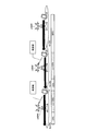
- FIG. 1 is an overall configuration diagram of a mobile communication system according to a first embodiment of the present invention.
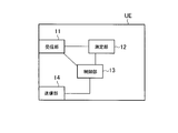
- FIG. 2 is a functional block diagram of the mobile station according to the first embodiment of the present invention.
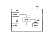
- FIG. 3 is a functional block diagram of the radio base station according to the first embodiment of the present invention.
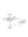
- FIG. 4 is a flowchart showing the operation of the mobile station according to the first embodiment of the present invention.
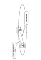
- FIG. 5 is an overall configuration diagram of a mobile communication system according to Modification 1 of the present invention.
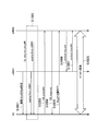
- FIG. 6 is a sequence diagram showing the operation of the mobile communication method according to the first modification of the present invention.
- FIG. 7 is a diagram for explaining the prior art.
- FIG. 8 is a diagram for explaining the prior art.
- FIG. 9 is a diagram for explaining the prior art.
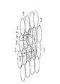
- Mobile communication system according to the first embodiment of the present invention A mobile communication system according to a first embodiment of the present invention will be described with reference to FIGS.
- the mobile communication system is an LTE or LTE-Advanced mobile communication system, and includes a radio base station eNB # 6 that manages cells # 1 to # 6, respectively.
- the mobile station UE is assumed to be in the “RRC_Connected state” in the cell # 1 under the radio base station eNB # 1. In the mobile communication system according to the present embodiment, the mobile station UE is assumed to be in the DRX state.
- the mobile station UE includes a receiving unit 11, a measuring unit 12, a control unit 13, and a transmitting unit 14.
- the receiving unit 11 is configured to receive various signals from the radio base station eNB # 1.
- the receiving unit 11 receives, from the radio base station eNB # 1, PDSCH (Physical Downlink Shared Channel), PDCCH (Physical Downlink Control), PCH (Paging Channel), PCH (Paging Channel), Bst, etc. It is configured to transmit a downlink signal.
- PDSCH Physical Downlink Shared Channel
- PDCCH Physical Downlink Control
- PCH Physical Channel
- PCH PCH
- Bst etc. It is configured to transmit a downlink signal.
- the reception unit 11 is configured to acquire information indicating the plurality of measurement target cells # 1 to # 6, for example, “RRC Connection Configuration”, “RRC Connection Reconfiguration”, and the like from the radio base station eNB # 1. ing.
- the measurement unit 12 is configured to measure downlink radio quality in the measurement target cells # 1 to # 6 described above.
- the control unit 13 is configured to perform various controls in the mobile station UE, for example, control related to DRX, control related to RLM, control related to handover, and the like.
- control unit 13 may be configured to detect RLF when the downlink radio quality in all of the plurality of measurement target cells # 1 to # 6 falls below a predetermined threshold.
- the above-described predetermined threshold value may be configured to be a common value in the cells # 1 to # 6, or may be configured to be different for each cell.
- control unit 13 performs RLF only when the mobile station UE is in the DRX state and when the downlink radio quality in all of the plurality of measurement target cells # 1 to # 6 falls below a predetermined threshold. It may be configured to detect.
- the measurement unit 12 may be configured to measure the downlink radio quality in all the measurement target cells # 1 to # 6 in “On duration”, or the measurement target cells # 1 to # 6. It may be configured to measure downlink radio quality in a part of # 6.
- control unit 13 may be configured to detect the RLF when the downlink radio quality in a predetermined number of cells out of the plurality of measurement target cells # 1 to # 6 falls below a predetermined threshold. .
- the transmission unit 14 is configured to transmit various signals to the radio base station eNB # 1.
- the transmission unit 14 transmits the PUSCH (Physical Uplink Shared Channel), the PUCCH (Physical Uplink Channel), the RACH (Random Access Channel), and the like to the radio base station eNB # 1 via the PUSCH (Physical Uplink Channel). Is configured to send.
- PUSCH Physical Uplink Shared Channel
- PUCCH Physical Uplink Channel
- RACH Random Access Channel
- the transmission unit 14 may be configured to transmit “Measurement Report” to the radio base station eNB # 1.
- the radio base station eNB includes a control unit 21, a management unit 22, a transmission unit 22, and a reception unit 24.
- the control unit 21 is configured to perform various controls in the radio base station eNB, for example, control related to DRX, control related to handover, and the like.
- the control unit 21 performs the handover of the mobile station UE to the measurement target cells # 2 to # 6. Is configured not to start.
- the management unit 22 is configured to manage various types of information related to the mobile station UE in the “RRC_Connected state”, for example, the measurement target cells # 1 to # 6 in the cells under the radio base station eNB.
- the transmission unit 23 is configured to transmit various signals to the mobile station UE, other radio base stations eNB, and upper nodes, and the reception unit 24 includes the mobile station UE, other radio base stations eNB, Various signals are received from an upper node or the like.
- the transmission unit 23 is configured to transmit a downlink signal to the mobile station UE via PDSCH, PDCCH, PCH, BCH, and the like.
- the transmission unit 23 may be configured to notify the mobile station UE of the above measurement target cells # 1 to # 6 using “RRC Connection Configuration” or “RRC Connection Reconfiguration”. .
- the radio base station eNB may be configured to determine a cell to be set as the measurement target cell according to a synchronization state with another radio base station eNB.
- the radio base station eNB may be configured to set a cell under control of another radio base station eNB that is synchronized to some extent as the measurement target cell.
- the receiving unit 24 is configured to receive an uplink signal from the mobile station UE via PUSCH, PUCCH, RACH (Random Access Channel), or the like.
- the receiving unit 24 may be configured to receive “Measurement Report” from the mobile station UE.
- step S101 the mobile station UE determines whether or not the downlink radio quality in any of the measurement target cells # 1 to # 6 exceeds a predetermined threshold value.
- step S102 the mobile station UE detects RLF.
- Modification 1 the mobile communication system according to the first modification of the present invention will be described with reference to FIG. 5 and FIG. 6 while focusing on differences from the mobile communication system according to the first embodiment described above.
- the mobile communication system according to the first modification is an LTE mobile communication system or an LTE-Advanced mobile communication system, and each of the radio base stations eNB # 8 and the like manages cells # 1 to # 6. It has.
- the mobile station UE is assumed to be in the “RRC_Connected state” in the cell # 1 under the radio base station eNB # 1. In the mobile communication system according to the first modification, the mobile station UE is in the DRX state. Furthermore, in the mobile communication system according to the first modification, it is assumed that the mobile station UE exists in the cover area of the cell # 2.
- step S1001 the radio base station eNB # 1 notifies the measurement target cells # 1 to # 6 to the mobile station UE.
- step S1002 the radio base stations eNB # 1 to # 6 managing the measurement target cells # 1 to # 6 perform the RA procedure for the mobile station UE with respect to the mobile station UE. Send Paging to get started.
- step S1003 the mobile station UE transmits “RA preamble” to the radio base station eNB # 2 in response to the paging, and in step S1004, the radio base station eNB # 2 transmits to the mobile station UE. Then, “RA response” is transmitted.
- the mobile station UE transmits an identifier of the mobile station UE to the radio base station eNB # 2, for example, IMSI (International Mobile Subscriber Identity), TMSI (Temporary Mobile Subscriber Identity), or C-RNTI (Cell-RNdi (Cell-RNdi).
- IMSI International Mobile Subscriber Identity
- TMSI Temporary Mobile Subscriber Identity
- C-RNTI Cell-RNdi (Cell-RNdi).
- Msg3 including Network Temporary Identifier is transmitted.
- the radio base station eNB # 2 identifies the mobile station UE according to the Msg3, and in step S1006, the radio base station eNB # 2 receives the “UE context” of the mobile station UE from the radio base stations eNB # 1 / eNB # 3 to eNB # 6. "Context request" is transmitted, and in step S1007, "UE context” of the mobile station UE is acquired from the radio base station eNB # 1.
- step S1008 U-plane is conducted between the mobile station UE and the radio base station eNB # 2.
- step S1002 the operation in step S1002 described above is omitted.
- Modification 2 the mobile communication system according to the second modification of the present invention will be described by focusing on differences from the mobile communication system according to the first embodiment described above.
- the transmission unit 14 of the mobile station UE notifies the radio base station eNB # 1 of the number of measurement target cells that can simultaneously monitor downlink signals. It is configured.
- the transmission unit 14 of the mobile station UE may be configured to perform such notification for each multiplex mode such as FDD (Frequency Division Duplex) or TDD (Time Division Duplex).
- FDD Frequency Division Duplex
- TDD Time Division Duplex
- the transmission unit 14 may be configured to notify the number of measurement target cells described above for each frequency band.
- the transmission part 14 may be comprised so that it may notify about the number of the said measurement object cells for every radio
- wireless function part for example, RF
- the first feature of the present embodiment is the mobile station UE, and when the downlink radio quality in all of the plurality of measurement target cells # 1 to # 6 is below a predetermined threshold, RLF (Radio Link Failure)
- the gist of the present invention is to include a control unit 13 configured to detect the above.
- the measurement target cells # 1 to # 6 may be configured to be notified by the radio base station eNB # 1.
- the communication carrier (operator) can appropriately set the measurement target cell in consideration of the communication environment, the operator policy, and the like.
- the above-described predetermined threshold may be configured to be different for each cell.
- the communication carrier can appropriately set the above-described predetermined threshold value in consideration of the communication environment and operator policy in each cell.
- control unit 13 is a downlink radio in the case where the mobile station UE is in the DRX state (intermittent reception state) and in all of the plurality of measurement target cells # 1 to # 6.
- the RLF may be detected only when the quality falls below a predetermined threshold.
- a second feature of the present embodiment is a mobile communication method, in which a mobile station UE in the DRX state starts a random access procedure with the radio base station eNB # 2, and a radio base station eNB # 2 has a step of acquiring “UE context (context information)” of the mobile station UE from the radio base station # 1 managing the measurement target cell # 1 of the mobile station UE.
- the U-plane can be conducted with the mobile station UE.
- the radio base station eNB # 2 transmits “Paging (paging signal)” in all of the measurement target cells # 1 to # 8 of the mobile station UE, whereby the mobile station UE There may be a step of starting a random access procedure.
- a third feature of the present embodiment is a mobile station UE, which is configured to notify the radio base station eNB of the number of measurement target cells that can simultaneously monitor downlink signals.
- the gist is that the transmitter 14 is provided.
- the radio base station eNB can set an appropriate number of measurement target cells for each mobile station UE.
- the transmission unit 14 may be configured to notify the number of measurement target cells described above for each frequency band.
- the transmission unit 14 may be configured to notify the number of measurement target cells for each wireless function unit.
- the radio base station eNB can flexibly set the measurement target cell in consideration of the frequency band and the state of the radio function unit.
- the operations of the mobile station UE and the radio base stations eNB # 1 to # 8 described above may be implemented by hardware, may be implemented by a software module executed by a processor, May be implemented.
- the software modules include RAM (Random Access Memory), flash memory, ROM (Read Only Memory), EPROM (Erasable Programmable ROM), EEPROM (Electronically Erasable and Programmable, Removable ROM, Hard Disk, and Removable ROM).
- RAM Random Access Memory
- flash memory ROM (Read Only Memory)
- EPROM Erasable Programmable ROM
- EEPROM Electrically Erasable and Programmable, Removable ROM, Hard Disk, and Removable ROM.
- it may be provided in a storage medium of an arbitrary format such as a CD-ROM.
- the storage medium is connected to the processor so that the processor can read and write information from and to the storage medium. Further, such a storage medium may be integrated in the processor. Such a storage medium and processor may be provided in the ASIC. Such an ASIC may be provided in the mobile station UE or the radio base stations eNB # 1 to # 8. Further, the storage medium and the processor may be provided in the mobile station UE and the radio base stations eNB # 1 to # 8 as discrete components.
- eNB radio base station UE ... mobile station 11, 24 ... reception unit 12 ... measurement unit 13, 21 ... control unit 14, 23 ... transmission unit 22 ... management unit
Landscapes
- Engineering & Computer Science (AREA)
- Computer Networks & Wireless Communication (AREA)
- Signal Processing (AREA)
- Mobile Radio Communication Systems (AREA)
Priority Applications (2)
| Application Number | Priority Date | Filing Date | Title |
|---|---|---|---|
| US14/655,294 US20150341857A1 (en) | 2012-12-28 | 2013-12-25 | Mobile station and mobile communication method |
| CN201380068288.XA CN104885557A (zh) | 2012-12-28 | 2013-12-25 | 移动台以及移动通信方法 |
Applications Claiming Priority (2)
| Application Number | Priority Date | Filing Date | Title |
|---|---|---|---|
| JP2012-288720 | 2012-12-28 | ||
| JP2012288720A JP6219566B2 (ja) | 2012-12-28 | 2012-12-28 | 移動局及び移動通信方法 |
Publications (1)
| Publication Number | Publication Date |
|---|---|
| WO2014104073A1 true WO2014104073A1 (ja) | 2014-07-03 |
Family
ID=51021151
Family Applications (1)
| Application Number | Title | Priority Date | Filing Date |
|---|---|---|---|
| PCT/JP2013/084613 Ceased WO2014104073A1 (ja) | 2012-12-28 | 2013-12-25 | 移動局及び移動通信方法 |
Country Status (4)
| Country | Link |
|---|---|
| US (1) | US20150341857A1 (enExample) |
| JP (1) | JP6219566B2 (enExample) |
| CN (1) | CN104885557A (enExample) |
| WO (1) | WO2014104073A1 (enExample) |
Families Citing this family (3)
| Publication number | Priority date | Publication date | Assignee | Title |
|---|---|---|---|---|
| JP2575954Y2 (ja) | 1992-09-18 | 1998-07-02 | 日産自動車株式会社 | オイルフィルタの取付構造 |
| US11012939B2 (en) | 2014-01-08 | 2021-05-18 | Huawei Technologies Co., Ltd. | System and method for always on connections in wireless communications system |
| CA3076844A1 (en) * | 2017-10-31 | 2019-05-09 | Guangdong Oppo Mobile Telecommunications Corp., Ltd. | Indication method for context identification, acquisition method, user equipment and base station |
Citations (8)
| Publication number | Priority date | Publication date | Assignee | Title |
|---|---|---|---|---|
| JP2011019074A (ja) * | 2009-07-08 | 2011-01-27 | Sharp Corp | 通信システム、移動局装置および基地局装置 |
| JP2011082616A (ja) * | 2009-10-02 | 2011-04-21 | Sharp Corp | 無線リンク障害検出方法、移動局装置、基地局装置および制御プログラム |
| JP2011082984A (ja) * | 2009-10-07 | 2011-04-21 | Innovative Sonic Corp | 無線通信システムにおける無線リンク障害をハンドリングする方法及び装置 |
| WO2011071037A1 (ja) * | 2009-12-09 | 2011-06-16 | シャープ株式会社 | 通信システム、移動局装置、無線リンク状態管理方法および集積回路 |
| JP2012503450A (ja) * | 2008-09-22 | 2012-02-02 | インターデイジタル パテント ホールディングス インコーポレイテッド | Drxモードにおけるlte無線リンク障害判定のための方法および装置 |
| JP2012520626A (ja) * | 2009-03-12 | 2012-09-06 | インターデイジタル パテント ホールディングス インコーポレイテッド | コンポーネントキャリアに特化した再構成を行うための方法および装置 |
| WO2012153525A1 (ja) * | 2011-05-11 | 2012-11-15 | 日本電気株式会社 | 無線通信システム、基地局装置及びそれに用いるハンドオーバ制御方法並びにそのプログラムが格納された記憶媒体 |
| JP2012227667A (ja) * | 2011-04-18 | 2012-11-15 | Kyocera Corp | 測定収集方法、基地局、及び無線端末 |
Family Cites Families (7)
| Publication number | Priority date | Publication date | Assignee | Title |
|---|---|---|---|---|
| US8830818B2 (en) * | 2007-06-07 | 2014-09-09 | Qualcomm Incorporated | Forward handover under radio link failure |
| ATE508609T1 (de) * | 2007-06-13 | 2011-05-15 | Ericsson Telefon Ab L M | Technik zum umgehen mit einem funkstreckenausfall in einem kommunikationsnetz |
| JP5052377B2 (ja) * | 2007-06-19 | 2012-10-17 | パナソニック株式会社 | 無線通信基地局装置、無線通信端末装置及びギャップ生成方法 |
| ES2763699T3 (es) * | 2010-01-07 | 2020-05-29 | Nec Corp | Sistema de comunicación radioeléctrica, terminal radioeléctrico, red radioeléctrica, procedimiento y programa de comunicación radioeléctrica |
| CN102711236B (zh) * | 2012-05-30 | 2015-08-19 | 华为终端有限公司 | 一种能力同步方法、设备及通信系统 |
| CN104365134B (zh) * | 2012-06-12 | 2019-01-04 | 诺基亚通信公司 | 通信方法和装置 |
| US9693306B2 (en) * | 2012-07-11 | 2017-06-27 | Blackberry Limited | Mechanisms to support UE power preference signaling |
-
2012
- 2012-12-28 JP JP2012288720A patent/JP6219566B2/ja not_active Expired - Fee Related
-
2013
- 2013-12-25 CN CN201380068288.XA patent/CN104885557A/zh active Pending
- 2013-12-25 US US14/655,294 patent/US20150341857A1/en not_active Abandoned
- 2013-12-25 WO PCT/JP2013/084613 patent/WO2014104073A1/ja not_active Ceased
Patent Citations (8)
| Publication number | Priority date | Publication date | Assignee | Title |
|---|---|---|---|---|
| JP2012503450A (ja) * | 2008-09-22 | 2012-02-02 | インターデイジタル パテント ホールディングス インコーポレイテッド | Drxモードにおけるlte無線リンク障害判定のための方法および装置 |
| JP2012520626A (ja) * | 2009-03-12 | 2012-09-06 | インターデイジタル パテント ホールディングス インコーポレイテッド | コンポーネントキャリアに特化した再構成を行うための方法および装置 |
| JP2011019074A (ja) * | 2009-07-08 | 2011-01-27 | Sharp Corp | 通信システム、移動局装置および基地局装置 |
| JP2011082616A (ja) * | 2009-10-02 | 2011-04-21 | Sharp Corp | 無線リンク障害検出方法、移動局装置、基地局装置および制御プログラム |
| JP2011082984A (ja) * | 2009-10-07 | 2011-04-21 | Innovative Sonic Corp | 無線通信システムにおける無線リンク障害をハンドリングする方法及び装置 |
| WO2011071037A1 (ja) * | 2009-12-09 | 2011-06-16 | シャープ株式会社 | 通信システム、移動局装置、無線リンク状態管理方法および集積回路 |
| JP2012227667A (ja) * | 2011-04-18 | 2012-11-15 | Kyocera Corp | 測定収集方法、基地局、及び無線端末 |
| WO2012153525A1 (ja) * | 2011-05-11 | 2012-11-15 | 日本電気株式会社 | 無線通信システム、基地局装置及びそれに用いるハンドオーバ制御方法並びにそのプログラムが格納された記憶媒体 |
Also Published As
| Publication number | Publication date |
|---|---|
| JP2014131229A (ja) | 2014-07-10 |
| JP6219566B2 (ja) | 2017-10-25 |
| US20150341857A1 (en) | 2015-11-26 |
| CN104885557A (zh) | 2015-09-02 |
Similar Documents
| Publication | Publication Date | Title |
|---|---|---|
| EP3753178B1 (en) | Bandwidth part switching and phy configuration alignment | |
| JP6504509B2 (ja) | 端末装置及び通信方法 | |
| US9756643B2 (en) | Method and apparatus for transmitting device-to-device related information in wireless communication system | |
| EP3442304A1 (en) | Method of handling radio link failure and related communication device | |
| US10390385B2 (en) | Method and apparatus for handling secondary cell deactivation timer in wireless communication system | |
| US10334653B2 (en) | Method for performing initial access in wireless communication system and device for same | |
| US9854495B2 (en) | Radio link failure reporting in a system using multiple cells | |
| WO2016133122A1 (ja) | ユーザ装置、及びタイマ制御方法 | |
| US20240414796A1 (en) | Special Cell Dormancy for New Radio | |
| EP3665935B1 (en) | Radio network node, wireless device and methods performed therein | |
| US20160255583A1 (en) | Radio base station, user terminal and radio communication method | |
| EP3145236A1 (en) | Device and method of handling information reporting in enhanced coverage and normal coverage | |
| US10051550B2 (en) | Method and apparatus for performing autonomous denial for dual connectivity in wireless communication system | |
| WO2016121877A1 (ja) | ユーザ装置、及びセル測定方法 | |
| US12213116B2 (en) | Special cell dormant bandwidth part switching | |
| WO2014054386A1 (ja) | 移動局及び無線基地局 | |
| JP6219566B2 (ja) | 移動局及び移動通信方法 | |
| EP3002985B1 (en) | Method and apparatus for handling release of simultaneous communication with multiple base stations and related communication device | |
| JP2014072638A (ja) | 無線基地局及び移動局 | |
| WO2014050395A1 (ja) | 移動局及び無線基地局 | |
| US10880054B2 (en) | Mobile station | |
| JP6410774B2 (ja) | 移動局 |
Legal Events
| Date | Code | Title | Description |
|---|---|---|---|
| 121 | Ep: the epo has been informed by wipo that ep was designated in this application |
Ref document number: 13867773 Country of ref document: EP Kind code of ref document: A1 |
|
| WWE | Wipo information: entry into national phase |
Ref document number: 14655294 Country of ref document: US |
|
| NENP | Non-entry into the national phase |
Ref country code: DE |
|
| 122 | Ep: pct application non-entry in european phase |
Ref document number: 13867773 Country of ref document: EP Kind code of ref document: A1 |