WO2014103820A1 - Dispositif de récupération de la chaleur résiduelle d'un moteur - Google Patents
Dispositif de récupération de la chaleur résiduelle d'un moteur Download PDFInfo
- Publication number
- WO2014103820A1 WO2014103820A1 PCT/JP2013/083842 JP2013083842W WO2014103820A1 WO 2014103820 A1 WO2014103820 A1 WO 2014103820A1 JP 2013083842 W JP2013083842 W JP 2013083842W WO 2014103820 A1 WO2014103820 A1 WO 2014103820A1
- Authority
- WO
- WIPO (PCT)
- Prior art keywords
- engine
- radiator
- waste heat
- refrigerant
- rankine cycle
- Prior art date
Links
Images


Classifications
-
- F—MECHANICAL ENGINEERING; LIGHTING; HEATING; WEAPONS; BLASTING
- F02—COMBUSTION ENGINES; HOT-GAS OR COMBUSTION-PRODUCT ENGINE PLANTS
- F02G—HOT GAS OR COMBUSTION-PRODUCT POSITIVE-DISPLACEMENT ENGINE PLANTS; USE OF WASTE HEAT OF COMBUSTION ENGINES; NOT OTHERWISE PROVIDED FOR
- F02G5/00—Profiting from waste heat of combustion engines, not otherwise provided for
- F02G5/02—Profiting from waste heat of exhaust gases
- F02G5/04—Profiting from waste heat of exhaust gases in combination with other waste heat from combustion engines
-
- F—MECHANICAL ENGINEERING; LIGHTING; HEATING; WEAPONS; BLASTING
- F01—MACHINES OR ENGINES IN GENERAL; ENGINE PLANTS IN GENERAL; STEAM ENGINES
- F01K—STEAM ENGINE PLANTS; STEAM ACCUMULATORS; ENGINE PLANTS NOT OTHERWISE PROVIDED FOR; ENGINES USING SPECIAL WORKING FLUIDS OR CYCLES
- F01K23/00—Plants characterised by more than one engine delivering power external to the plant, the engines being driven by different fluids
- F01K23/02—Plants characterised by more than one engine delivering power external to the plant, the engines being driven by different fluids the engine cycles being thermally coupled
- F01K23/06—Plants characterised by more than one engine delivering power external to the plant, the engines being driven by different fluids the engine cycles being thermally coupled combustion heat from one cycle heating the fluid in another cycle
- F01K23/065—Plants characterised by more than one engine delivering power external to the plant, the engines being driven by different fluids the engine cycles being thermally coupled combustion heat from one cycle heating the fluid in another cycle the combustion taking place in an internal combustion piston engine, e.g. a diesel engine
-
- F—MECHANICAL ENGINEERING; LIGHTING; HEATING; WEAPONS; BLASTING
- F01—MACHINES OR ENGINES IN GENERAL; ENGINE PLANTS IN GENERAL; STEAM ENGINES
- F01K—STEAM ENGINE PLANTS; STEAM ACCUMULATORS; ENGINE PLANTS NOT OTHERWISE PROVIDED FOR; ENGINES USING SPECIAL WORKING FLUIDS OR CYCLES
- F01K23/00—Plants characterised by more than one engine delivering power external to the plant, the engines being driven by different fluids
- F01K23/02—Plants characterised by more than one engine delivering power external to the plant, the engines being driven by different fluids the engine cycles being thermally coupled
- F01K23/06—Plants characterised by more than one engine delivering power external to the plant, the engines being driven by different fluids the engine cycles being thermally coupled combustion heat from one cycle heating the fluid in another cycle
- F01K23/10—Plants characterised by more than one engine delivering power external to the plant, the engines being driven by different fluids the engine cycles being thermally coupled combustion heat from one cycle heating the fluid in another cycle with exhaust fluid of one cycle heating the fluid in another cycle
-
- F—MECHANICAL ENGINEERING; LIGHTING; HEATING; WEAPONS; BLASTING
- F01—MACHINES OR ENGINES IN GENERAL; ENGINE PLANTS IN GENERAL; STEAM ENGINES
- F01K—STEAM ENGINE PLANTS; STEAM ACCUMULATORS; ENGINE PLANTS NOT OTHERWISE PROVIDED FOR; ENGINES USING SPECIAL WORKING FLUIDS OR CYCLES
- F01K27/00—Plants for converting heat or fluid energy into mechanical energy, not otherwise provided for
- F01K27/02—Plants modified to use their waste heat, other than that of exhaust, e.g. engine-friction heat
-
- F—MECHANICAL ENGINEERING; LIGHTING; HEATING; WEAPONS; BLASTING
- F02—COMBUSTION ENGINES; HOT-GAS OR COMBUSTION-PRODUCT ENGINE PLANTS
- F02D—CONTROLLING COMBUSTION ENGINES
- F02D29/00—Controlling engines, such controlling being peculiar to the devices driven thereby, the devices being other than parts or accessories essential to engine operation, e.g. controlling of engines by signals external thereto
- F02D29/02—Controlling engines, such controlling being peculiar to the devices driven thereby, the devices being other than parts or accessories essential to engine operation, e.g. controlling of engines by signals external thereto peculiar to engines driving vehicles; peculiar to engines driving variable pitch propellers
-
- F—MECHANICAL ENGINEERING; LIGHTING; HEATING; WEAPONS; BLASTING
- F01—MACHINES OR ENGINES IN GENERAL; ENGINE PLANTS IN GENERAL; STEAM ENGINES
- F01N—GAS-FLOW SILENCERS OR EXHAUST APPARATUS FOR MACHINES OR ENGINES IN GENERAL; GAS-FLOW SILENCERS OR EXHAUST APPARATUS FOR INTERNAL COMBUSTION ENGINES
- F01N13/00—Exhaust or silencing apparatus characterised by constructional features ; Exhaust or silencing apparatus, or parts thereof, having pertinent characteristics not provided for in, or of interest apart from, groups F01N1/00 - F01N5/00, F01N9/00, F01N11/00
- F01N13/011—Exhaust or silencing apparatus characterised by constructional features ; Exhaust or silencing apparatus, or parts thereof, having pertinent characteristics not provided for in, or of interest apart from, groups F01N1/00 - F01N5/00, F01N9/00, F01N11/00 having two or more purifying devices arranged in parallel
-
- F—MECHANICAL ENGINEERING; LIGHTING; HEATING; WEAPONS; BLASTING
- F01—MACHINES OR ENGINES IN GENERAL; ENGINE PLANTS IN GENERAL; STEAM ENGINES
- F01N—GAS-FLOW SILENCERS OR EXHAUST APPARATUS FOR MACHINES OR ENGINES IN GENERAL; GAS-FLOW SILENCERS OR EXHAUST APPARATUS FOR INTERNAL COMBUSTION ENGINES
- F01N2410/00—By-passing, at least partially, exhaust from inlet to outlet of apparatus, to atmosphere or to other device
-
- F—MECHANICAL ENGINEERING; LIGHTING; HEATING; WEAPONS; BLASTING
- F01—MACHINES OR ENGINES IN GENERAL; ENGINE PLANTS IN GENERAL; STEAM ENGINES
- F01N—GAS-FLOW SILENCERS OR EXHAUST APPARATUS FOR MACHINES OR ENGINES IN GENERAL; GAS-FLOW SILENCERS OR EXHAUST APPARATUS FOR INTERNAL COMBUSTION ENGINES
- F01N5/00—Exhaust or silencing apparatus combined or associated with devices profiting from exhaust energy
- F01N5/02—Exhaust or silencing apparatus combined or associated with devices profiting from exhaust energy the devices using heat
-
- F—MECHANICAL ENGINEERING; LIGHTING; HEATING; WEAPONS; BLASTING
- F02—COMBUSTION ENGINES; HOT-GAS OR COMBUSTION-PRODUCT ENGINE PLANTS
- F02B—INTERNAL-COMBUSTION PISTON ENGINES; COMBUSTION ENGINES IN GENERAL
- F02B41/00—Engines characterised by special means for improving conversion of heat or pressure energy into mechanical power
- F02B41/02—Engines with prolonged expansion
- F02B41/10—Engines with prolonged expansion in exhaust turbines
-
- F—MECHANICAL ENGINEERING; LIGHTING; HEATING; WEAPONS; BLASTING
- F02—COMBUSTION ENGINES; HOT-GAS OR COMBUSTION-PRODUCT ENGINE PLANTS
- F02G—HOT GAS OR COMBUSTION-PRODUCT POSITIVE-DISPLACEMENT ENGINE PLANTS; USE OF WASTE HEAT OF COMBUSTION ENGINES; NOT OTHERWISE PROVIDED FOR
- F02G2260/00—Recuperating heat from exhaust gases of combustion engines and heat from cooling circuits
-
- Y—GENERAL TAGGING OF NEW TECHNOLOGICAL DEVELOPMENTS; GENERAL TAGGING OF CROSS-SECTIONAL TECHNOLOGIES SPANNING OVER SEVERAL SECTIONS OF THE IPC; TECHNICAL SUBJECTS COVERED BY FORMER USPC CROSS-REFERENCE ART COLLECTIONS [XRACs] AND DIGESTS
- Y02—TECHNOLOGIES OR APPLICATIONS FOR MITIGATION OR ADAPTATION AGAINST CLIMATE CHANGE
- Y02T—CLIMATE CHANGE MITIGATION TECHNOLOGIES RELATED TO TRANSPORTATION
- Y02T10/00—Road transport of goods or passengers
- Y02T10/10—Internal combustion engine [ICE] based vehicles
- Y02T10/12—Improving ICE efficiencies
Definitions
- This invention relates to an engine waste heat utilization device.
- JP2010-101283A discloses a vehicle including an electromagnetic clutch between a refrigerant pump and an engine constituting a Rankine cycle system.
- An object of the present invention is to provide a waste heat utilization device capable of suppressing engine overheating even when a refrigerant pump abnormality occurs in which the refrigerant pump is in an operating state in a non-operating region of the Rankine cycle system.
- An engine waste heat utilization apparatus uses a radiator that cools engine cooling water, a heat exchanger that recovers engine waste heat into a refrigerant, and a refrigerant discharged from the heat exchanger.
- the waste heat utilization device has an operation region restriction that restricts the operation region of the engine when a refrigerant pump abnormality that causes the refrigerant pump to operate in the non-operation region of the Rankine cycle system occurs than when the refrigerant pump abnormality does not occur.
- engine maximum output limiting means for limiting engine maximum output when refrigerant pump abnormality occurs in the non-operating region of Rankine cycle system when refrigerant pump abnormality occurs, compared with when refrigerant pump abnormality does not occur, Rankine cycle system
- One of the maximum vehicle speed limiting means for limiting the maximum vehicle speed of the vehicle having the engine when the abnormality of the refrigerant pump that causes the refrigerant pump to operate in the non-operating region occurs than when the abnormality of the refrigerant pump does not occur.
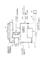
- FIG. 1 is a schematic configuration diagram of an engine waste heat utilization apparatus according to a first embodiment of the present invention.
- FIG. 2A is a schematic cross-sectional view of an expander pump in which the pump and the expander are integrated.
- FIG. 2B is a schematic cross-sectional view of the refrigerant pump.
- FIG. 2C is a schematic cross-sectional view of the expander.
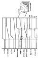
- FIG. 3 is a schematic view showing the function of the refrigerant system valve.
- FIG. 4 is a schematic configuration diagram of the hybrid vehicle.
- FIG. 5 is a perspective view of the engine.
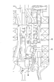
- FIG. 6 is a schematic view of the arrangement of the exhaust pipe as viewed from below the vehicle.
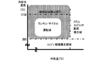
- FIG. 7A is a characteristic diagram of a Rankine cycle operation region.
- FIG. 7A is a characteristic diagram of a Rankine cycle operation region.
- FIG. 7B is a characteristic diagram of a Rankine cycle operation region.
- FIG. 8 is a timing chart showing a state when the hybrid vehicle is accelerated while assisting the rotation of the engine output shaft by the expander torque.
- FIG. 9 is a timing chart showing a state when the Rankine cycle system is restarted after being stopped.
- FIG. 10 shows the heat dissipation amount of the radiator when the Rankine cycle system is not operated and the clutch is not fixed, and the total heat dissipation amount of the radiator and the heat dissipation amount of the condenser when the Rankine cycle is not operated and the drive clutch is fixed. It is the figure which showed the relationship.
- FIG. 11 is a side view of the condenser and the radiator as viewed from the side of the vehicle.
- FIG. 12 is a characteristic diagram showing the relationship between the distance from the front of the vehicle and the air temperature.
- FIG. 13 is an engine operation region diagram for explaining the update of the boundary between the radiator performance NG region and the radiator performance OK region.
- FIG. 14A is a flowchart for explaining the update of the boundary between the radiator performance NG area and the radiator performance OK area.
- FIG. 14B is a flowchart for explaining the update of the boundary between the radiator performance NG area and the radiator performance OK area.
- FIG. 15 is a characteristic diagram of the heat dissipation amount of the condenser.
- FIG. 16 is a characteristic diagram of the total heat radiation capacity of the radiator and the condenser.
- FIG. 17 is a characteristic diagram of the outside air temperature correction coefficient.
- FIG. 18 is a characteristic diagram of the air conditioner load correction amount.
- FIG. 19 is an operation region map for explaining the update of the boundary between the radiator performance NG region and the radiator performance OK region.
- FIG. 20 is an operation region map for explaining the boundary between the radiator performance NG region and the radiator performance OK region when the outside air temperatures are different.
- FIG. 21 is a flowchart for explaining the limitation of the amount of supplied fuel.
- FIG. 22 is an operation region map after the boundary between the radiator performance NG region and the radiator performance OK boundary region is updated.
- FIG. 23 is a flowchart for explaining the operation of the engine waste heat utilization apparatus according to the second embodiment.
- FIG. 24 is a flowchart for explaining the operation of the engine waste heat utilization apparatus according to the third embodiment.
- FIG. 25 is a characteristic diagram of the engine maximum output.
- FIG. 19 is an operation region map for explaining the update of the boundary between the radiator performance NG region and the radiator performance OK region.
- FIG. 20 is an operation region map for explaining the boundary between the radiator
- FIG. 26 is a flowchart for explaining the operation of the engine waste heat utilization apparatus according to the fourth embodiment.
- FIG. 27 is a characteristic diagram of the basic maximum vehicle speed.
- FIG. 28 is a characteristic diagram of the outside air temperature correction coefficient.
- FIG. 29 is a schematic configuration diagram of an engine waste heat utilization device according to a fifth embodiment.
- FIG. 30 is a schematic configuration diagram of an engine waste heat utilization device according to a sixth embodiment.
- FIG. 1 is a schematic configuration diagram of an engine waste heat utilization apparatus according to a first embodiment of the present invention.
- the engine waste heat utilization device includes a Rankine cycle system 31.
- the Rankine cycle system 31 is configured to share the refrigerant and the condenser 38 with respect to the refrigeration cycle system 51.
- a system in which the Rankine cycle system 31 and the refrigeration cycle system 51 are integrated is referred to as an integrated cycle system 30.
- the integrated cycle system 30 circulates cooling water and exhaust in addition to a circuit in which the refrigerant of the Rankine cycle system 31 and the refrigeration cycle system 51 circulates, and components such as a pump, an expander, and a condenser provided in the circuit. It shall refer to the entire system including circuits.
- FIG. 4 is a schematic configuration diagram of the hybrid vehicle 1 on which the integrated cycle system 30 is mounted.
- the engine 2 In the hybrid vehicle 1, the engine 2, the motor generator 81, and the automatic transmission 82 are connected in series. The output of the automatic transmission 82 is transmitted to the drive wheels 85 via the propeller shaft 83 and the differential gear 84.
- a first drive shaft clutch 86 is provided between the engine 2 and the motor generator 81.
- the automatic transmission 82 includes a second drive shaft clutch 87 as a friction engagement element. The first drive shaft clutch 86 and the second drive shaft clutch 87 are connected to the engine controller 71, and the connection state is controlled according to the driving conditions of the hybrid vehicle 1. As shown in FIG.
- the hybrid vehicle 1 when the vehicle speed is in the EV traveling region where the efficiency of the engine 2 is poor, the engine 2 is stopped, the first drive shaft clutch 86 is shut off, and the second drive shaft clutch 87 is turned on. Connected, the hybrid vehicle 1 travels only with the driving force of the motor generator 81. On the other hand, when the vehicle speed deviates from the EV travel region and shifts to the Rankine cycle operation region, the engine 2 is operated and the Rankine cycle system 31 is set to the operation state.
- the engine 2 includes an exhaust passage 3.
- the exhaust passage 3 is composed of an exhaust manifold 4 and an exhaust pipe 5 connected to a collecting portion of the exhaust manifold 4.
- a bypass exhaust pipe 6 branches off from the exhaust pipe 5, and a waste heat recovery unit 22 for exchanging heat between the exhaust and the cooling water is provided in the exhaust pipe 5 in a section bypassed by the bypass exhaust pipe 6. Is provided.
- the waste heat recovery unit 22 and the bypass exhaust pipe 6 are integrated to form a waste heat recovery unit 23.
- the waste heat recovery unit 23 includes an underfloor catalyst 88 and a sub-muffler 89 downstream of the catalyst. It is arranged between.
- the cooling water that has flowed through these passages 13 and 14 is rejoined by a thermostat valve 15 that determines the distribution of the cooling water flow rate, and returns to the engine 2 via the cooling water pump 16.
- the cooling water pump 16 is driven by the engine 2 and its rotation speed is synchronized with the engine rotation speed.
- the bypass cooling water passage 14 that bypasses the radiator 11 is branched from the cooling water passage 13 and directly connected to the heat exchanger 36, and is branched from the cooling water passage 13 to waste heat recovery unit 22.
- the second bypass cooling water passage 25 connected to the heat exchanger 36 after passing through.
- the thermostat valve 15 increases the valve opening on the coolant passage 13 side, and relatively increases the amount of coolant passing through the radiator 11.
- the thermostat valve 15 reduces the valve opening on the cooling water passage 13 side and relatively reduces the amount of cooling water passing through the radiator 11.
- the cooling water temperature is particularly low, such as before the engine 2 is warmed up, the entire amount of the cooling water bypasses the radiator 11 and flows through the bypass cooling water passage 14.
- the valve opening on the bypass cooling water passage 14 side is not fully closed.
- the flow rate of the cooling water flowing through the radiator 11 increases, the flow rate of the cooling water flowing through the bypass cooling water passage 14 is lower than when the entire amount of cooling water flows through the bypass cooling water passage 14 side. However, it is configured so that the flow does not stop completely.
- a heat exchanger 36 for exchanging heat with the refrigerant of the Rankine cycle system 31 is provided in the bypass cooling water passage 14.
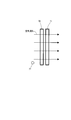
- the heat exchanger 36 is an integrated heater and superheater.
- two cooling water passages 36a and 36b are provided in approximately one row, and a refrigerant passage 36c through which the refrigerant of the Rankine cycle system 31 flows is provided adjacent to the cooling water passages 36a and 36b.
- Each passage 36a, 36b, 36c is configured such that the flow directions of the refrigerant and the cooling water are opposite to each other when the entire heat exchanger 36 is viewed from above.
- the cooling water passage 36 a located on the upstream side (left side in FIG. 1) for the refrigerant of the Rankine cycle system 31 is connected to the first bypass cooling water passage 24. Cooling water from the engine 2 is directly introduced into the left portion of the heat exchanger including the cooling water passage 36a, and the left portion of the heat exchanger functions as a heater for heating the refrigerant of the Rankine cycle system 31 flowing through the refrigerant passage 36c. .
- the cooling water passage 36 b located on the downstream side (right side in FIG. 1) for the refrigerant of the Rankine cycle system 31 is connected to the waste heat recovery device 22 via the second bypass cooling water passage 25. Cooling water that has passed through the waste heat recovery unit 22, that is, cooling water that has been overheated by the exhaust discharged from the engine 2, is introduced into the right side portion of the heat exchanger including the cooling water passage 36 b.
- the right part of the heat exchanger functions as a superheater that superheats the refrigerant flowing through the refrigerant passage 36c.
- the cooling water passage 22 a of the waste heat recovery unit 22 is provided adjacent to the exhaust pipe 5. By introducing the cooling water discharged from the engine 2 into the cooling water passage 22a of the waste heat recovery unit 22, the cooling water can be heated to, for example, about 110 to 115 ° C. by high-temperature exhaust.
- the cooling water passage 22a is configured such that the flow directions of the exhaust gas and the cooling water are opposite to each other when the entire waste heat recovery unit 22 is viewed from above.
- a control valve 26 is interposed in the second bypass cooling water passage 25 provided with the waste heat recovery unit 22.
- the cooling water temperature inside the engine 2 (engine water temperature) exceeds an allowable temperature (for example, 100 ° C.) for preventing deterioration of the efficiency of the engine 2 and knocking. So that the opening of the control valve 26 is reduced.
- the engine water temperature approaches the permissible temperature, the amount of cooling water passing through the waste heat recovery device 22 is reduced, so that it is possible to reliably prevent the engine water temperature from exceeding the permissible temperature.
- the exhaust pipe 5 includes a bypass exhaust pipe 6 that bypasses the waste heat recovery unit 22, and a thermostat valve 7 that controls the exhaust passage amount of the waste heat recovery unit 22 and the exhaust passage amount of the bypass exhaust pipe 6. And are provided.
- the thermostat valve 7 is disposed at a branch portion of the exhaust pipe 5.
- the valve opening of the thermostat valve 7 is based on the temperature of the cooling water exiting the waste heat recovery unit 22 so that the temperature of the cooling water exiting the waste heat recovery unit 22 does not exceed a predetermined temperature (for example, a boiling temperature of 120 ° C.). Adjusted.
- a predetermined temperature for example, a boiling temperature of 120 ° C.
- the heat exchanger 36, the thermostat valve 7 and the waste heat recovery unit 22 are integrated as a waste heat recovery unit 23.
- the waste heat recovery unit 23 is disposed in the middle of the exhaust pipe under the floor at the approximate center in the vehicle width direction.
- the thermostat valve 7 may be a relatively simple temperature sensing valve using bimetal or the like, or may be a control valve controlled by a controller based on a detection value of a temperature sensor. Since the adjustment of the heat exchange amount by the thermostat valve 7 involves a relatively large delay, if the thermostat valve 7 is adjusted alone, it is difficult to prevent the engine water temperature from exceeding the allowable temperature.
- control valve 26 of the second bypass cooling water passage 25 is controlled based on the engine water temperature, it is possible to quickly reduce the amount of heat recovery and reliably prevent the engine water temperature from exceeding the allowable temperature. it can. Further, if the engine water temperature is sufficiently lower than the allowable temperature, heat is generated until the temperature of the cooling water discharged from the waste heat recovery unit 22 reaches a temperature exceeding the allowable temperature of the engine water temperature (eg, 110 to 115 ° C.). Since the replacement is performed, the amount of waste heat recovered can be increased.
- the cooling water that has exited the cooling water passage 36 b joins the first bypass cooling water passage 24 via the second bypass cooling water passage 25.
- the Rankine cycle system 31 is configured as a part of the integrated cycle system 30 integrated with the refrigeration cycle system 51.
- Rankine cycle system 31 is a system that recovers waste heat of engine 2 into a refrigerant via cooling water of engine 2 and regenerates the recovered waste heat as power.
- the Rankine cycle system 31 includes a refrigerant pump 32, a heat exchanger 36, an expander 37, and a condenser 38.
- Each component of the Rankine cycle system 31 is connected by refrigerant passages 41 to 44 through which a refrigerant such as R134a circulates.
- the shaft 32a (rotary shaft) of the refrigerant pump 32 is connected to the output shaft of the expander 37 on the same shaft.
- the refrigerant pump 32 is driven by the output (power) generated by the expander 37, and the power generated by the refrigerant pump 32 is supplied to the output shaft (crankshaft) of the engine 2.
- the shaft 32 a of the refrigerant pump 32 and the output shaft of the expander 37 are arranged in parallel with the output shaft of the engine 2.
- a belt 34 is wound between a pump pulley 33 provided at the tip of a shaft 32 a of the refrigerant pump 32 and a crank pulley 2 a of the engine 2.
- the refrigerant pump 32 is a gear type pump as shown in FIG. 2B
- the expander 37 is a scroll type expander as shown in FIG. 2C.
- an electromagnetic drive clutch 35 (drive mechanism) is provided between the pump pulley 33 and the refrigerant pump 32.
- the drive clutch 35 is configured to be able to change the connection state between the refrigerant pump 32 and the expander 37 and the engine 2.
- the drive clutch 35 is connected when the output generated by the expander 37 exceeds the driving force or the like of the refrigerant pump 32 (when the predicted expander torque is positive), and the engine is generated by the output generated by the expander 37.
- the rotation of the second output shaft is assisted. By assisting the rotation of the output shaft of the engine 2 using the energy obtained by the waste heat recovery, the fuel consumption can be improved. Further, the energy for driving the refrigerant pump 32 that circulates the refrigerant can also be covered by the recovered waste heat.
- the refrigerant from the refrigerant pump 32 is supplied to the heat exchanger 36 via the refrigerant passage 41.
- heat exchanger 36 heat exchange is performed between the coolant of the engine 2 and the refrigerant, and the refrigerant is vaporized.
- the refrigerant discharged from the heat exchanger 36 is supplied to the expander 37 through the refrigerant passage 42.
- the expander 37 is a steam turbine that converts heat into rotational energy by expanding the vaporized and superheated refrigerant.
- the power recovered by the expander 37 drives the refrigerant pump 32 and is transmitted to the engine 2 via the drive clutch 35, the belt 34, and the like.
- the refrigerant discharged from the expander 37 is supplied to the condenser 38 via the refrigerant passage 43.
- the condenser 38 heat exchange is performed between the outside air and the refrigerant, and the refrigerant is cooled and liquefied.
- the condenser 38 and the radiator 11 are arranged in parallel, and the condenser 38 and the radiator 11 are configured to be cooled by the radiator fan 12.
- the refrigerant liquefied by the condenser 38 is guided to the refrigerant pump 32 through the refrigerant passage 44.
- the refrigerant guided to the refrigerant pump 32 is sent again to the heat exchanger 36 by the refrigerant pump 32.
- the refrigerant circulates in the Rankine cycle system 31.
- the refrigeration cycle system 51 shares the refrigerant of the Rankine cycle system 31, the configuration of the refrigeration cycle system 51 is simplified.
- the refrigeration cycle system 51 includes a compressor 52, a condenser 38, and an evaporator 55.
- the compressor 52 is a fluid machine that compresses the refrigerant of the refrigeration cycle system 51 to a high temperature and a high pressure, and is driven by the engine 2.
- a compressor pulley 53 is fixed to the drive shaft of the compressor 52, and a belt 34 is wound around the compressor pulley 53 and the crank pulley 2a.
- the driving force of the engine 2 is transmitted to the compressor pulley 53 via the belt 34, and the compressor 52 is driven.
- An electromagnetic compressor clutch 54 is provided between the compressor pulley 53 and the compressor 52.
- the compressor clutch 54 is configured to connect and disconnect the compressor 52 and the compressor pulley 53.
- the refrigerant discharged from the compressor 52 flows into the refrigerant passage 43 via the refrigerant passage 56 and is then supplied to the condenser 38.
- the condenser 38 is a heat exchanger that condenses and liquefies the refrigerant by heat exchange with the outside air.
- the refrigerant discharged from the condenser 38 is supplied to the evaporator 55 via the refrigerant passage 57 branched from the refrigerant passage 44.
- the evaporator 55 is provided in the case of the air conditioner unit together with the heater core.
- the evaporator 55 is a heat exchanger that evaporates the refrigerant from the condenser 38 and cools the conditioned air sent from the blower fan by latent heat of evaporation.
- the refrigerant evaporated by the evaporator 55 is returned to the compressor 52 through the refrigerant passage 58. Note that the mixing ratio of the conditioned air cooled by the evaporator 55 and the conditioned air heated by the heater core is adjusted to a temperature set by the occupant according to the opening of the air mix door.
- a plurality of valves are provided to control the refrigerant flowing in the cycle.
- a pump upstream valve 61 is provided in the refrigerant passage 44 connecting the refrigeration cycle branch point 45 and the refrigerant pump 32, and the refrigerant connecting the heat exchanger 36 and the expander 37.
- An expansion machine upstream valve 62 is provided in the passage 42.
- a check valve 63 is provided in the refrigerant passage 41 connecting the refrigerant pump 32 and the heat exchanger 36 to prevent the refrigerant from flowing back from the heat exchanger 36 to the refrigerant pump 32, and the expander 37 and the refrigeration cycle junction 46 are
- a check valve 64 is provided in the refrigerant passage 43 that connects the refrigerant passage 43 to prevent the refrigerant from flowing back from the refrigeration cycle junction 46 to the expander 37.
- the Rankine cycle system 31 also includes an expander bypass passage 65 that bypasses the expander 37 from the upstream side of the expander upstream valve 62 and merges upstream of the check valve 64, and the expander bypass passage 65 includes a bypass valve 66. Is provided.
- a pressure regulating valve 68 is provided in the passage 67 that bypasses the bypass valve 66.
- an air conditioner circuit valve 69 is provided in a refrigerant passage 57 that connects the refrigeration cycle branch point 45 and the evaporator 55. All of the four valves 61, 62, 66, and 69 described above are electromagnetic on-off valves.
- the engine controller 71 receives an expander upstream pressure signal detected by the pressure sensor 72, a refrigerant pressure Pd signal at the outlet of the condenser 38 detected by the pressure sensor 73, a rotation speed signal of the expander 37, and the like. The Based on these input signals, the engine controller 71 controls the compressor 52 and the radiator fan 12 of the refrigeration cycle system 51 according to the operating conditions, and valves 61, 62, 66, 69, etc. according to the operating conditions. Open / close control is performed.
- the controller 71 predicts the expander torque (regenerative power) based on the expander upstream pressure and the expander rotational speed, and assists the rotation of the engine output shaft when the predicted expander torque is positive.
- the drive clutch 35 is engaged.
- the controller 71 releases the drive clutch 35 when the predicted expander torque is zero or negative.
- the expander torque can be predicted with higher accuracy than when the expander torque (regenerative power) is predicted from the exhaust temperature. As a result, it is possible to appropriately engage and disengage the drive clutch 35 in accordance with the state of expansion machine torque generation. For details on this point, JP2010-190185A is helpful.
- the four on-off valves 61, 62, 66, 69 and the two check valves 63, 64 are refrigerant valves, and these valves will be described with reference to FIG.
- the pump upstream valve 61 is closed under a predetermined condition in which the refrigerant tends to be biased in the circuit of the Rankine cycle system 31 as compared with the circuit of the refrigeration cycle system 51, so that the refrigerant ( This is a valve for preventing the bias of the lubricating component).
- the pump upstream valve 61 closes the circuit of the Rankine cycle system 31 in cooperation with a check valve 64 disposed downstream of the expander 37.
- the expander upstream valve 62 is a valve for blocking the refrigerant passage 42 and increasing the refrigerant pressure to a predetermined pressure when the pressure of the refrigerant discharged from the heat exchanger 36 is relatively low. Thereby, even when the expander torque is not sufficiently obtained, the heating of the refrigerant is promoted, and for example, the time until the Rankine cycle system 31 is restarted (the time during which regeneration is possible) can be shortened.
- the bypass valve 66 is opened so that the refrigerant pump 32 can be operated by the refrigerant bypassing the expander 37 when the amount of refrigerant existing on the Rankine cycle system 31 side is not sufficient when the Rankine cycle system 31 is started. . Thereby, the starting time of Rankine cycle system 31 can be shortened. Since the refrigerant pump 32 is operated in a state where the refrigerant bypasses the expander 37, the refrigerant temperature at the outlet of the condenser 38 and the inlet of the refrigerant pump 32 has decreased to a predetermined value or more from the boiling point considering the pressure at those portions. In this case, it can be determined that a state in which sufficient liquid refrigerant can be supplied to the Rankine cycle 3 system 1 is ready.
- the check valve 63 disposed upstream of the heat exchanger 36 cooperates with the bypass valve 66, the pressure adjustment valve 68, and the expander upstream valve 62, and holds the refrigerant supplied to the expander 37 at a high pressure. Under the condition that the regeneration efficiency of the Rankine cycle system 31 is low, the operation of the Rankine cycle system 31 is stopped, and the circuit is closed over the front and rear sections of the heat exchanger 36. By raising the refrigerant pressure during the stop in this way, it becomes possible to restart the Rankine cycle system 31 quickly using the high-pressure refrigerant.
- the pressure regulating valve 68 opens when the pressure of the refrigerant supplied to the expander 37 becomes too high, and functions as a relief valve that releases the refrigerant that has become too high.
- the check valve 64 disposed downstream of the expander 37 cooperates with the pump upstream valve 61 to prevent the refrigerant from being biased toward the Rankine cycle system 31. If the engine 2 is not warmed immediately after the start of the operation of the hybrid vehicle 1, the Rankine cycle system 31 becomes cooler than the refrigeration cycle system 51, and the refrigerant may be biased toward the Rankine cycle system 31. In particular, immediately after the start of vehicle operation in summer, the cooling capacity is most demanded, so there is a demand for eliminating the uneven distribution of refrigerant and ensuring the cooling capacity.
- the check valve 64 is provided to prevent the refrigerant from being unevenly distributed on the Rankine cycle system 31 side.
- the compressor 52 has a structure in which refrigerant cannot freely pass when driving is stopped.
- the compressor 52 cooperates with the air conditioner circuit valve 69 to prevent the refrigerant from being biased toward the refrigeration cycle system 51.
- the refrigerant moves from the Rankine cycle system 31 side having a relatively high refrigerant temperature during steady operation to the refrigeration cycle system 51 side, and the refrigerant circulating in the Rankine cycle system 31 is changed. There may be a shortage.
- the temperature of the evaporator 55 is low immediately after the cooling is stopped, and the refrigerant tends to accumulate in the evaporator 55 having a low temperature and a relatively large volume.
- FIG. 5 is a perspective view of the engine 2 mounted on the vehicle. As shown in FIG. 5, the heat exchanger 36 is disposed vertically above the exhaust manifold 4 of the engine 2. By disposing the heat exchanger 36 in the space above the exhaust manifold 4, the mountability of the Rankine cycle system 31 to the engine 2 can be improved.
- the engine 2 is provided with a tension pulley 8 that applies a predetermined tension to the belt 34.
- FIG. 7A and 7B are operation region diagrams of the Rankine cycle system 31.
- FIG. FIG. 7A is an operation region diagram of Rankine cycle system 31 when the horizontal axis is the outside air temperature and the vertical axis is the engine water temperature (cooling water temperature).
- FIG. 7B is an operation region diagram of the Rankine cycle system 31 when the horizontal axis is the engine rotation speed and the vertical axis is the engine torque (engine load).
- the Rankine cycle system 31 is operated when predetermined Rankine cycle operation conditions are satisfied in FIGS. 7A and 7B.
- the operation of the Rankine cycle system 31 is stopped in a region on the low water temperature side where priority is given to warm-up of the engine 2 and a region on the high outside air temperature side where the load on the compressor 52 increases.
- the Rankine cycle system 31 is not operated, so that the coolant temperature is quickly raised.
- the Rankine cycle system 31 is stopped, sufficient refrigerant is provided to the refrigeration cycle system 51, and the cooling capacity is increased.
- the operation of the Rankine cycle system 31 is stopped in the EV travel region and the region on the high rotation speed side where the friction of the expander 37 increases. .
- the dimensions and the like of each part of the expander 37 are set such that the friction is small and the efficiency is high in the engine rotation speed range where the operation frequency is high.
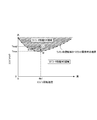
- FIG. 8 is a timing chart showing a state when the hybrid vehicle 1 is accelerated while assisting the rotation of the engine output shaft by the expander torque.
- an expander torque map showing how the operating state of the expander 37 changes during acceleration is shown.
- the expander torque becomes the largest in the portion where the expander rotational speed is low and the expander upstream pressure is high (upper left portion).
- the expander torque decreases as the expander rotational speed increases and the expander upstream pressure decreases (lower right side).
- the shaded area indicates a region where the expander torque becomes negative and the refrigerant pump 32 becomes a load on the engine.
- the constant speed running is continued until t1 when the driver steps on the accelerator pedal, and the expander 37 generates a positive torque.
- the rotation assist of the engine output shaft is performed by the expander torque.
- the rotation speed of the expander 37 that is, the rotation speed of the refrigerant pump 32 increases in proportion to the engine rotation speed, but the rises in the exhaust temperature and the cooling water temperature are delayed with respect to the increase in the engine rotation speed. . Therefore, the ratio of the recoverable heat amount to the refrigerant amount increased by the increase in the rotational speed of the refrigerant pump 32 is reduced. Therefore, even if the rotation speed of the expander increases, the refrigerant pressure upstream of the expander decreases and the expander torque decreases.
- the expander upstream valve 62 is switched from the open state to the closed state, for example, at time t2 when the expander torque becomes substantially zero. . Thereby, the phenomenon that the expander 37 is dragged to the engine 2 due to the decrease in the expander torque is avoided, and the deterioration of the regeneration efficiency is prevented.
- the drive clutch 35 is switched from the connected state (engaged state) to the disconnected state (released state).
- the refrigerant pressure upstream of the expander can be sufficiently reduced. Thereby, it is possible to prevent the expander 37 from over-rotating when the drive clutch 35 is disconnected.
- a large amount of refrigerant is supplied into the heat exchanger 36 by the refrigerant pump 32, and the Rankine cycle system 31 is smoothly restarted by effectively heating the refrigerant even when the Rankine cycle system 31 is stopped. .
- the expander upstream pressure rises again due to the increase in the heat dissipation of the engine 2.
- the expander upstream valve 62 is switched from the closed state to the open state, and the supply of the refrigerant to the expander 37 is resumed.
- the drive clutch 35 is connected again. By reconnecting the drive clutch 35, rotation assist of the engine output shaft by the expander torque is resumed.
- FIG. 9 is a timing immming chart showing a state in which the Rankine cycle system 31 is restarted in a mode different from FIG. 8 (control of t4) from the operation stop state in which the expander upstream valve 62 is closed and the drive clutch 35 is disconnected. It is.
- the heat release amount of the engine 2 increases, and the increase in the heat release amount increases the temperature of the cooling water flowing into the heat exchanger 36, and the temperature of the refrigerant in the heat exchanger 36.
- the expander upstream valve 62 is in the closed state, the refrigerant pressure upstream of the expander upstream valve 62, that is, the expander upstream pressure increases as the refrigerant temperature rises by the heat exchanger 36 (t11 to t12). ).
- This change in operating state switches the operating range of the engine 2 from the Rankine cycle non-operating range to the Rankine cycle operating range.
- the expander upstream valve 62 is not provided, when the shift to the Rankine cycle operation region is performed, the drive clutch 35 is immediately switched to the connected state and the expander 37 is coupled to the engine output shaft. A torque shock occurs due to the load on the engine 2.
- the expander upstream valve 62 when switching to the Rankine cycle operation region, the expander upstream valve 62 is not immediately switched from the closed state to the open state. That is, the closed state of the expander upstream valve 62 is continued even after shifting to the Rankine cycle operation region. Thereafter, the drive of the expander 37 is permitted at the timing t12 when the differential pressure between the expander upstream pressure and the expander downstream pressure becomes equal to or higher than a predetermined pressure, and the expander upstream valve 62 is switched from the closed state to the open state. In this way, when the expander upstream valve 62 is switched to the open state, a predetermined pressure of refrigerant is supplied to the expander 37, and the expander rotation speed rapidly increases from zero.
- the drive clutch 35 is switched from the disconnected state to the connected state at timing t13 when the expander rotational speed reaches the engine rotational speed. If the drive clutch 35 is connected before the expander 37 sufficiently increases the rotational speed, the expander 37 becomes an engine load and a torque shock occurs. On the other hand, by connecting the drive clutch 35 at t13 when there is no difference in rotational speed from the engine output shaft, the expander 37 is prevented from becoming an engine load, and the occurrence of torque shock is prevented.
- clutch sticking may occur.
- the engine 2 and the refrigerant pump 32 are always connected (refrigerant pump abnormality occurrence state), and the refrigerant pump 32 operates even when unnecessary.
- the drive clutch 35 is an electromagnetic clutch.
- the drive clutch 35 is brought into a clutch engagement state in which two members are engaged by generating electromagnetic force by energizing the solenoid coil, and the two members are separated by stopping energization of the solenoid coil and disappearing the electromagnetic force.
- the clutch is disengaged.
- the drive clutch 35 when a large slip input acts on the two members when the clutch is engaged, the two members may be seized and the clutch may be fixed. Further, in the drive clutch 35, the clutch can be stuck due to deterioration with time. Furthermore, since energization and de-energization of the solenoid is performed by the relay in the drive clutch 35, the clutch can be stuck even if a relay failure occurs.
- the refrigerant pump 32 When the clutch is fixed so that the engine 2 and the refrigerant pump 32 are always connected, the refrigerant pump 32 is always driven by the engine 2 as shown in FIG. Therefore, even though the operation region is the non-operation region of the Rankine cycle system 31, the Rankine cycle system 31 is substantially in an operation state, and the refrigerant 38 radiates heat in the condenser 38.
- the condenser 38 since the condenser 38 is disposed on the front surface of the radiator 11, the heat release of the coolant in the radiator 11 is inhibited by the heat release of the refrigerant in the condenser 38.
- the bar graph on the left side of FIG. 10 shows the heat radiation amount of the radiator 11 when the operating point is in the non-operating region of the Rankine cycle system 31 and the drive clutch 35 is not fixed.
- the bar graph on the right side of FIG. 10 shows the total amount of heat released from the radiator 11 and the condenser 38 when the operating point is in the non-operating region of the Rankine cycle system 31 and the drive clutch 35 is stuck.
- the time when the drive clutch 35 is not fixed is referred to as “when the clutch is not fixed”
- the time when the drive clutch 35 is fixed is referred to as “when the clutch is fixed”.
- the Rankine cycle non-operation area is abbreviated as “Rankine non-operation area”.
- the total heat dissipation amount of the radiator 11 and the condenser 38 when the clutch is fixed is lower than the heat dissipation amount of the radiator 11 when the clutch is not fixed. This is a matter that the present inventors have found for the first time. Since the heat of the refrigerant is radiated by the condenser 38 of the Rankine cycle system 31 and the heat of the cooling water is radiated by the radiator 11 when the clutch is fixed, the total amount of heat radiated from the condenser 38 and radiator 11 is It is likely to coincide with the heat dissipation amount of the radiator 11 when not fixed.
- the total heat dissipation amount of the radiator 11 and the condenser 38 when the clutch is fixed is lower than the heat dissipation amount of the radiator 11 when the clutch is not fixed. This is because the flow rate of the refrigerant circulating through the Rankine cycle system 31 is limited, and the heat radiation amount of the condenser 38 is limited, and the heat radiation efficiency of the radiator 11 deteriorates due to the heat radiation of the condenser 38. This is probably because of this.
- FIG. 11 is a view of the condenser 38 and the radiator 11 arranged on the front surface of the vehicle 1 as viewed from the side of the vehicle.
- the condenser 38 is disposed in front of the radiator 11.
- the traveling wind passes from the front side of the vehicle in the order of the condenser 38 and the radiator 11 and flows toward the rear of the vehicle.
- the refrigerant flowing through the condenser 38 and the cooling water flowing through the radiator 11 are higher than the outside air, the heat of the refrigerant is radiated by the condenser 38 and the heat of the cooling water is radiated by the radiator 11, so the condenser 38 and the radiator When passing through 11, the temperature of the traveling wind rises.
- FIG. 12 is a characteristic diagram showing the temperature change of the air passing through the condenser 38 and the radiator 11 as shown in FIG.
- the horizontal axis represents the distance from the front of the vehicle.
- the condenser 38 is located between the predetermined value a and the predetermined value b at a distance from the front surface of the vehicle, and the radiator 11 is located between the predetermined value c and the predetermined value d.
- the solid line in FIG. 12 shows the change in air temperature when the Rankine cycle is not operating and when the clutch is not locked.
- the condenser 38 does not radiate heat, so the air temperature remains at the outside air temperature T1 until the distance from the vehicle front surface reaches the predetermined value c.
- the temperature of the air rises linearly when the distance from the front of the vehicle is between the predetermined value c and the predetermined value d, and the predetermined temperature T4 become.
- the temperature of the air does not rise any further, so that after the predetermined value d, it remains at the predetermined temperature T4.
- the broken line in FIG. 12 shows the change in the air temperature when the Rankine cycle is not operating and the clutch is fixed.
- the Rankine cycle system 31 is operated due to the clutch being fixed, so that the refrigerant radiates heat in the condenser 38. Therefore, when the air passes through the condenser 38, the air receives heat from the condenser 38, and therefore, the air temperature is changed from the outside air temperature T1 to the predetermined temperature T2 when the distance from the vehicle front is between the predetermined value a and the predetermined value b. To rise. The temperature of the air that has passed through the condenser 38 does not rise until it reaches the radiator 11.
- the air receives heat from the radiator 11, so that the temperature of the air rises linearly when the distance from the front of the vehicle is between the predetermined value c and the predetermined value d, and the predetermined temperature T3 become.
- the temperature rise when passing through the radiator 11 is smaller than that in the Rankine cycle non-operating region and when the clutch is not fixed, the temperature of the air after passing through the radiator 11 reaches only a predetermined temperature T3 lower than the predetermined temperature T4. .
- the temperature of the air leaving the radiator 11 is lower when the clutch is fixed than when the clutch is not fixed.
- the air side heat radiation amount Q of the radiator 11 is obtained by the equation (1).
- the condenser 38 dissipates heat when the Rankine cycle is not operating and the clutch is fixed, the air temperature Ta on the front surface of the radiator 11 rises, so that the difference between the radiator inlet cooling water temperature Tw and the radiator front air temperature Ta is as shown in FIG. Get smaller. If it does so, according to said (1) Formula, the air side heat radiation amount Q of a radiator will fall rather than the case where the condenser 38 does not radiate heat. This means that when air passes through the radiator 11, the inclination of the temperature rise of the air when the Rankine cycle is not operating and when the clutch is fixed is smaller than that when the Rankine cycle is not operating and when the clutch is not fixed. means. Therefore, when the difference between the radiator inlet cooling water temperature Tw and the radiator front air temperature Ta becomes small due to the influence of the heat radiation of the condenser 38, the heat radiation efficiency of the radiator 11 deteriorates.
- the controller 71 limits the engine operating range when the Rankine cycle is not operated and the clutch is fixed, as compared to when the Rankine cycle is not operated and the clutch is not fixed.
- FIG. 13 is an engine operation region diagram in which the horizontal axis represents the engine rotation speed and the vertical axis represents the engine torque.
- a thin line at the lower right that is drawn substantially in parallel is an engine heat dissipation amount line (equal engine output line), and the upper right thin line indicates that the engine heat dissipation amount is larger (the engine output becomes higher).
- the heat dissipation efficiency of the radiator 11 is worse than when the clutch is not fixed, and the radiator performance NG region is substantially increased to the position of the one-dot chain line as shown in FIG. Enlarge. That is, the radiator performance OK region is substantially narrowed.
- the radiator performance OK region is substantially narrowed.
- the Rankine cycle non-operating area when the operating point is in the region sandwiched between the thick line and the one-dot chain line, what was in the radiator performance OK area when the clutch is not fixed is in the radiator performance NG area when the clutch is fixed, Overheating can occur.
- the heat radiation performance component that inhibits the heat radiation of the radiator 11 due to the heat radiation of the condenser 38 when the clutch is fixed is converted into the engine output, and the engine torque obtained from the converted engine output is a predetermined value. Calculate as A. Then, the boundary between the radiator performance NG region and the radiator performance OK region is moved downward in FIG. 13 by a predetermined value A to expand the radiator performance NG region and narrow the radiator performance OK region.
- FIG. 13 shows three load / load lines B, C, and D.
- Line B is a road / load line when the vehicle is driven at a constant vehicle speed of 40 km / h.
- Line C is a road / load line for driving a vehicle at a constant 60 km / h
- line D is a road / load line for driving a vehicle at a constant 80 km / h.
- the point E which is the intersection of the downwardly protruding thick line and line B is the radiator performance OK range (engine operating range) It becomes the limit. That is, the engine rotational speed G at point E becomes the maximum engine rotational speed, and the engine torque I at point E becomes the maximum engine torque.
- the boundary between the two areas shifts from the thick line to the one-dot chain line when the Rankine cycle non-operating area and the clutch are fixed.
- the point F that is the intersection of the alternate long and short dash line and the line B is the limit of the radiator performance OK region. That is, the engine rotational speed H at point F becomes the maximum engine rotational speed, and the engine torque J at point F becomes the maximum engine torque.
- the maximum rotational speed decreases from G to H, and the maximum engine torque decreases from I to J.
- 14A and 14B show the control for updating the boundary between the two regions so that the radiator performance NG region is expanded and the radiator performance OK region is narrowed when the Rankine cycle is not operated and the clutch is fixed.
- This control is repeatedly executed at a constant time period (for example, a period of 10 milliseconds).
- step 1 the controller 71 determines whether or not the operating point of the engine 2 is in the Rankine cycle non-operating region.
- 7A and 7B the operating range of the Rankine cycle system 31 has been described, but the remaining operating range excluding the operating range of the Rankine cycle system 31 is the Rankine cycle non-operating range.
- the reason for being in the Rankine cycle non-operating region is that overheating may occur in the Rankine cycle non-operating region.
- the controller 71 determines in step 2 whether or not the drive clutch 35 is in the clutch-fixed state.
- Whether the drive clutch 35 is stuck or not is determined based on a pump shaft rotational speed sensor 75 (see FIG. 1) that detects the rotational speed of the shaft 32a of the refrigerant pump 32. By stopping energization of the solenoid coil in the Rankine cycle non-operating region, the drive clutch 35 is released. Therefore, when the shaft 32a of the refrigerant pump 32 is rotating even in the Rankine cycle non-operating region, it can be determined that the clutch is stuck.
- the controller 71 determines that the drive clutch 35 is stuck. Information (determination result) on whether or not the drive clutch 35 is stuck is stored in the memory of the controller 71. If the drive clutch 35 is not fixed, the controller 71 ends the current process.
- the processes in steps 3 to 16 are processes for expanding the radiator performance NG area and narrowing the radiator performance OK area.
- step 3 the heat release amount Pcond [kW] of the condenser 38 when the Rankine cycle is not operated and the clutch is fixed is calculated.
- the heat release amount Pcond of the condenser 38 is calculated on the basis of the Rankine cycle non-operating region and the refrigerant flow rate when the clutch is fixed, the refrigerant pressure / temperature, and the vehicle speed.
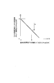
- the heat release amount Pcond of the condenser 38 increases as the vehicle speed VSP increases, as shown in FIG. .
- the vehicle speed is detected by a vehicle speed sensor 79 (see FIG. 1).
- the controller 71 executes step 4.
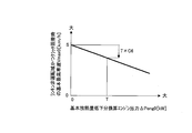
- the controller 71 searches a table having the contents shown in FIG. 16 based on the heat radiation amount Pcond of the condenser 38, and the total heat radiation capacity Ptotl [kW] of the radiator 11 and the condenser 38 when the Rankine cycle is not operated and the clutch is fixed. Is calculated.
- the heat radiation capability Ptotl decreases as the heat radiation amount Pcond of the condenser 38 increases.
- the characteristics of FIG. 16 represent a decrease in the total heat dissipation capability of the radiator 11 and the condenser 38 due to the heat dissipation inhibition in the radiator 11 described in FIG.
- the characteristic of FIG. 16 also indicates that the ratio of the heat dissipation of the radiator 11 is increased as the heat dissipation amount of the condenser 38 is increased.
- step 5 the controller 71 divides the actual engine output Peng [kW] by the heat release amount Prad [kW] of the radiator 11 according to the equation (2) to calculate a conversion coefficient K [unknown number] for the engine output.
- the actual engine output Peng on the right side of equation (2) and the heat release amount Prad of the radiator 11 are values when the Rankine cycle is not operated and the clutch is fixed.
- the actual engine output Peng is calculated based on the intake air amount Qa detected by the air flow meter 76 (see FIG. 1).
- the heat dissipation amount Prad of the radiator 11 is calculated based on the Rankine cycle non-operating region and the coolant flow rate when the clutch is fixed, the coolant pressure / temperature, and the vehicle speed.
- Step 6 the controller 71 multiplies the engine output conversion coefficient K and the total heat dissipation capability Ptotl by the equation (3), and calculates the engine output ⁇ Peng0 [kW], which is the basic heat dissipation decrease corresponding to the Rankine cycle non-operating range and the clutch being fixed. Is calculated.
- the coefficient K is smaller than 1.0 from the equation (2), and ⁇ Peng0 from the equation (3). Is corrected to the decreasing side.
- the actual engine output Peng is smaller than the radiator heat dissipation amount Prad when the Rankine cycle is not operated and the clutch is fixed, there is a margin in the heat dissipation of the radiator 11. In this case, by correcting ⁇ Peng0 to the decreasing side, it is avoided that the radiator performance OK region is set unnecessarily narrow.
- K is a coefficient for reflecting the relationship between the actual engine output Peng and the heat dissipation amount Prad of the radiator 11 in the engine output corresponding to the decrease in the heat dissipation amount when the Rankine cycle is not operated and the clutch is fixed.
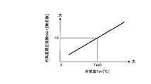
- step 7 the controller 71 calculates an outside air temperature correction coefficient Kair1 [unnamed number] by searching a table having the contents shown in FIG. 17 from the outside air temperature Tair detected by the outside air temperature sensor 77 (see FIG. 1). .
- Step 8 the controller 71 multiplies the outside air temperature correction coefficient Kair1 and ⁇ Peng0 by the equation (4) to calculate a target heat radiation amount reduction equivalent engine output ⁇ Peng [kW] when the Rankine cycle is not operating and the clutch is fixed.
- the outside air temperature correction coefficient Kair1 is 1.0 when the outside air temperature Tair0 at the time of adaptation (initial setting) is 1 and is 1 when the actual outside air temperature Tair is higher than the outside air temperature Tair0 at the time of adaptation.
- a value greater than 0.0 The reason why ⁇ Peng0 is corrected to increase when the actual outside air temperature is higher than the outside air temperature at the time of adaptation is that overheating is more likely to occur when the actual outside air temperature is higher than the outside air temperature at the time of adaptation.
- the outside air temperature correction coefficient Kair1 becomes a value smaller than 1.0. This is because overheating is less likely to occur when the actual outside air temperature is lower than the outside air temperature at the time of adaptation, and ⁇ Peng0 can be corrected to the reduction side accordingly.
- step 9 the controller 71 calculates the basic torque margin Marg0 [N ⁇ m] by dividing the target heat radiation reduction conversion engine output ⁇ Peng by the engine rotational speed Ne at that time according to the equation (5).
- the basic torque margin in the equation (5) is an amount by which the boundary between the radiator performance NG region and the radiator performance OK region is moved to the engine torque decreasing side.
- the boundary between the radiator performance NG region and the radiator performance OK region is expanded by a predetermined value A toward the engine torque decreasing side, but the basic torque margin Marg0 is a value corresponding to the predetermined value A.
- the controller 71 determines whether or not there is an air conditioner load.
- the compressor 52 for the air conditioner is driven by the engine 2. Therefore, when there is an air conditioner load, the compressor clutch 54 is in a connected state, and the compressor 52 and the engine 2 are connected. It is connected via a compressor clutch 54.
- the compressor clutch 54 is an electromagnetic clutch, and is connected when an ON signal is received, and is disconnected when an OFF signal is received.
- the controller 71 determines the presence or absence of an air conditioner load based on the ON / OFF signal to the compressor clutch 54. That is, when the signal to the compressor clutch 54 is an ON signal, the controller 71 determines that there is an air conditioner load, and executes the processing from step 11 onward.
- Steps 11 to 13 are processes for correcting the basic torque margin Marg0 to the increase side when there is an air conditioner load.
- the controller 71 calculates the air conditioner load Laircon.
- the air conditioner load Laircon include a set temperature and the number of passengers.
- the air conditioner load Laircon is set to zero when the actual set temperature is the set temperature at the time of adaptation (initial setting) or when the actual number of passengers matches the number of passengers at the time of adaptation (initial setting).
- the air conditioner load Laircon is set to a larger positive value as the actual set temperature is lower than the set temperature at the time of adaptation or as the actual number of occupants is greater than the number of occupants at the time of adaptation.
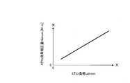
- Step 12 the controller 71 calculates an air conditioner load correction amount Haircon [N ⁇ m] by searching a table having the contents shown in FIG. 18 from the air conditioner load Laircon.
- the controller 71 calculates the target torque margin Marg [N ⁇ m] by adding the air conditioner load correction amount Haircon and the basic torque margin Marg0 using equation (6).
- the air conditioner load correction amount Haircon increases as the air conditioner load Laircon increases. Therefore, the target torque margin Marg increases as the air conditioner load Laircon increases.
- the boundary between the radiator performance NG region and the radiator performance OK region when the air conditioner load is present is updated to the engine torque decreasing side as compared with the case where there is no air conditioner load. That is, the radiator performance NG area is expanded and the radiator performance OK area is narrowed. This is because the load on the engine 2 is greater when there is an air conditioner load than when there is no air conditioner load, and the cooling water temperature rises and the engine 2 is more likely to overheat. Therefore, the radiator performance NG range is expanded accordingly. This is to narrow the radiator performance OK region.
- step 10 determines that the signal to the compressor clutch 54 is an OFF signal
- the controller 71 determines that there is no air conditioner load, and executes the process of step 14.
- the controller 71 sets the basic torque margin Marg0 as it is to the target torque margin Marg.
- Steps 15 and 16 are processes for updating the boundary between the radiator performance NG area and the radiator performance OK area using the target torque margin Marg calculated as described above.
- step 15 the controller 71 reads the operation region map of the engine 2.
- FIG. 19 is an example of the read driving region map.
- an area map including this boundary is stored in the ROM or the like. It is remembered.
- an area map stored at the time of vehicle shipment from the factory is read out.
- the controller 71 uses the target torque margin Marg to update the boundary between the radiator performance NG region and the radiator performance OK region to the engine torque decreasing side, and stores the updated region map. For example, when the boundary between the updated radiator performance NG region and the radiator performance OK region becomes a one-dot chain line shown in FIG. 19, a region map including the updated boundary is stored as a new engine operation region map.
- the area map at the time of factory shipment shown in FIG. 19 is a case where the actual outside air temperature matches the outside air temperature at the time of adaptation.
- FIG. 20 when the actual outside air temperature is different from the outside air temperature at the time of adaptation, particularly when the actual outside air temperature is higher than the outside air temperature at the time of adaptation, the boundary between the radiator performance NG area and the radiator performance OK area The change will be described.
- the boundary between the radiator performance NG region and the radiator performance OK region is in the position of the solid line when the outside air temperature at the time of adaptation is 20 ° C. and the Rankine cycle non-operation region and the clutch is not fixed.
- the boundary between the radiator performance NG region and the radiator performance OK region moves to the position of the one-dot chain line in order to suppress overheating when the clutch is locked even in the Rankine cycle non-operating region.
- the boundary between the radiator performance NG region and the radiator performance OK region becomes higher as the actual outside air temperature becomes higher than 25 ° C, 30 ° C, 40 ° C from the outside air temperature at the time of adaptation.
- the radiator performance NG region is expanded and the radiator performance OK region is narrowed as the actual outside air temperature is higher than the outside air temperature at the time of adaptation. This is because the radiator 11 is less likely to dissipate heat as the actual outside air temperature is higher than the adapted outside temperature, and overheating is more likely to occur than at the adapted outside temperature, and the radiator performance NG region needs to be expanded accordingly. It is.
- the boundary of the operation region of the engine 2 is determined by the maximum fuel supply amount, the maximum throttle valve opening, the maximum engine speed, and the like. Therefore, in order to operate the engine 2 in the narrower radiator OK region, the amount of supplied fuel should be reduced so that it returns to the boundary of the narrower radiator OK region when the operating point belongs to the enlarged radiator performance NG region. Good. Instead of the supplied fuel amount, the throttle valve opening, the engine speed, and the like may be decreased.
- a method of operating the engine 2 in a narrow radiator OK region by reducing the amount of supplied fuel will be described.
- FIG. 21 is a flowchart showing control for reducing the amount of supplied fuel when the operating point determined from the engine torque and the engine rotation speed belongs to the radiator performance NG region. This control is repeatedly executed at a constant time period (for example, a period of 10 milliseconds).
- the engine 2 is a gasoline engine.
- Steps 21 and 22 the controller 71 determines whether or not the Rankine cycle is not operating and whether or not the clutch is locked. If it is not in the Rankine cycle non-operating range, or if it is not in the Rankine cycle operating range and the clutch is not locked, the controller 71 ends the current control.
- step 23 the controller 71 calculates a basic fuel supply amount Qf0.
- a fuel injection valve is provided in an intake port or a combustion chamber, and fuel at a predetermined pressure is supplied by opening the fuel injection valve at a predetermined timing.
- the fuel pressure is constant, the period during which the fuel injection valve is open (injection pulse width) is proportional to the amount of fuel supplied. Therefore, in the engine 2, the basic injection pulse width is based on the intake air amount Qa detected by the air flow meter 76 (see FIG. 1) and the engine rotational speed Ne detected by the crank angle sensor 78 (see FIG. 1). Tp [ms] is calculated. This basic injection pulse width Tp is used as the basic fuel supply amount Qf0.
- step 24 the controller 71 multiplies the intake air amount Qa detected by the air flow meter 76 (see FIG. 1) by the conversion coefficient C2 according to the equation (7), and calculates the actual Rankin cycle non-operating range and the actual state when the clutch is fixed. Engine output Peng [kW] is calculated.
- step 25 the controller 71 divides the actual engine output Peng [kW] by the engine speed Ne at that time according to the equation (8), and calculates the actual engine torque Torq [ N ⁇ m] is calculated.
- Torq C1 ⁇ Peng / Ne (8)
- Step 26 the controller 71 determines whether the operating point determined from the actual engine torque Torq and the actual engine operating rotational speed Ne when the clutch is locked and the Rankine cycle non-operating region belongs to the radiator performance NG region on the operating region map. Determine whether or not.
- the operation region map used here is an operation region map in which the boundary between the radiator performance NG region and the radiator performance OK boundary region is updated as shown in FIG.
- the operating point determined by Torq1 and Ne1 when the Rankine cycle is not operated and the clutch is fixed, the operating point determined by Torq1 and Ne1. Becomes the L point in the enlarged radiator performance NG region.
- overheating may occur. In order to suppress overheating, it is necessary to move the operating point to the position of the alternate long and short dash line that is the boundary between the radiator performance OK region and the radiator performance OK region.
- the engine torque is reduced toward the M point, or the engine torque and the engine speed are reduced toward the N point. You may be allowed to.
- the amount of supplied fuel is decreased, and therefore the engine torque is decreased toward the point M in FIG.
- the controller 71 executes the processing of steps 27 to 29 in FIG. 21 in order to move the operating point from the L point to the M point.
- Steps 27 to 29 are processes for returning the operating point to the boundary of the radiator performance OK region by decreasing the amount of supplied fuel when the operating point belongs to the radiator performance NG region.
- step 27 the controller 71 calculates a maximum torque Tmax at the engine rotation speed Ne1 at that time by searching a region map having the contents shown in FIG. 22 from the engine rotation speed Ne1.
- the maximum torque Tmax is the following value. That is, in the operation region map of FIG. 22, a vertical line is drawn from the predetermined value Ne1 toward the boundary between the radiator performance NG region and the radiator performance OK region, and a lead line is drawn to the left from the point where the vertical line intersects the boundary. The engine torque at the position where the lead line intersects the vertical axis is the maximum torque Tmax.
- step 28 the controller 71 calculates the supplied fuel decrease amount Hgen1 by the equation (9) based on the difference between the actual engine torque Torq1 at point L and the maximum torque Tmax with respect to the engine rotational speed Ne1 at point L.
- Hgen1 C3 ⁇ (Torq ⁇ Tmax) (9)
- C3 Conversion factor for engine torque
- step 29 the controller 71 calculates a target supply fuel amount mQf by subtracting the supply fuel decrease amount Hgen1 from the basic supply fuel amount Qf0 according to equation (10).
- the reason why the amount of fuel supplied is reduced by the equation (10) is to reduce the torque generated in the engine 2 and move the operating point to the engine torque decreasing side in the operating region map of FIG.
- the controller 71 calculates the supply fuel decrease amount Hgen1 of equation (9) in the same unit [ms] as the basic injection pulse width Tp. Assuming that the supplied fuel decrease amount calculated in this way is Hgen1 ′, a value obtained by subtracting Hgen1 ′ from the basic injection pulse width Tp becomes the corrected basic injection pulse width HTp, and the fuel injection pulse width Ti is calculated according to the known equation (11). [Ms] can be calculated. This fuel injection pulse width Ti is used as the target supply fuel amount mQf.
- step 30 the controller 71 executes the process of step 30 because it is not necessary to limit the amount of fuel supplied.
- the controller 71 sets the basic supply fuel amount Qf0 as it is as the target supply fuel amount mQf.
- the controller 71 calculates the fuel injection pulse width Ti [ms] using the basic injection pulse width Tp according to the equation (12). This fuel injection pulse width Ti is used as the target supply fuel amount mQf.
- the controller 71 outputs the target supply fuel amount mQf calculated as described above to the fuel supply device.
- the controller 71 controls the fuel injection valve so that the fuel injection valve as the fuel supply device is opened with the calculated fuel injection pulse width Ti.
- the inventors have determined that the amount of heat released from the radiator 11 when the Rankine cycle is not operating and when the clutch is not locked (when the refrigerant pump is not abnormal) is higher than when the Rankine cycle is not operating and when the clutch is locked (the refrigerant pump is abnormal). It was found that the amount of heat released from the radiator 11 and the condenser 38 at the same time was reduced. For this reason, when the Rankine cycle is not operated and the clutch is fixed, the temperature of the engine cooling water rises by the amount of heat radiation that is different from that when the Rankine cycle is not operated and the clutch is not fixed, and the engine 2 is overheated depending on the operating point. There is a fear. *
- the waste heat utilization apparatus of the present embodiment is powered by using the radiator 11 that cools the cooling water of the engine 2, the heat exchanger 36 that recovers the waste heat of the engine 2 to the refrigerant, and the refrigerant discharged from the heat exchanger 36.
- the Rankine cycle system 31 in which the condenser 38 and the radiator 11 are arranged in order, and a drive mechanism such as a drive clutch 35 that drives the refrigerant pump 32 are provided.
- the controller 71 (operating region limiting means) operates when the Rankine cycle is not operating and the clutch is locked (when the refrigerant pump is abnormal), and when the Rankine cycle is not operating and the clutch is not fixed (the refrigerant pump is not abnormal). ),
- the radiator performance OK region engine operation region
- the radiator performance OK region is limited (see steps 1 to 9 in FIG. 14A, steps 10, 14, 15, 16, and FIG. 19 in FIG. 14B).
- the controller 71 performs the radiator performance OK by the basic heat radiation amount decrease equivalent conversion engine output ⁇ Peng0 (the value obtained by converting the heat radiation decrease amount in which the heat radiation of the radiator 11 is inhibited by the heat radiation of the condenser 38 as the engine output).
- the area is narrowed (see steps 3 to 9 in FIG. 14A, steps 10, 14, 15, 16, and FIG. 19 in FIG. 14B). Thereby, generation
- the heat dissipation performance of the radiator 11 decreases as the outside air temperature Tair is higher than the outside air temperature Tair0 at the time of adaptation.
- the controller 71 narrows the radiator performance OK region as the outside air temperature Tair is higher (Steps 7, 8, 9 in FIG. 14A, Steps 10, 14, 15, 16, FIG. FIG. 20). Thereby, even if the outside temperature Tair becomes higher than the outside temperature Tair0 at the time of adaptation, the occurrence of overheating can be suppressed.
- the controller 71 narrows the radiator performance OK region when the air conditioner load acts on the engine 2 than when the air conditioner load does not act (steps 10, 11, 12, 13, and FIG. 14B). 15, 16). Thereby, generation
- FIG. 23 is a flowchart showing control for restricting the air conditioner operation. This control is repeatedly executed at a constant time period (for example, a period of 10 milliseconds).
- Steps 41 and 42 the controller 71 determines whether or not it is in the Rankine cycle non-operation region, and determines whether or not the clutch is locked. If it is not the Rankine cycle non-operating range, or if it is not the Rankine cycle operating range and the clutch is not locked, the controller 71 ends the current process.
- the controller 71 determines in step 43 whether or not the air conditioner is operating. This determination is made based on the state of the air conditioner switch and the compressor clutch 54. The controller 71 determines that the air conditioner is not operating, for example, when the air conditioner switch is OFF.
- the controller 71 ends the current process. On the other hand, if the air conditioner switch is ON and the air conditioner is operating, the controller 71 increases the temperature in the vehicle compartment by a predetermined value in step 44.
- the compressor clutch 54 is driven and controlled based on the ON duty signal from the controller 71.
- the ON duty is increased, the connection ratio of the clutch 54 per fixed time increases relatively, and the compressor 52 works well.
- the ON duty is decreased, the connection ratio of the clutch 54 per fixed time is relatively decreased, and the function of the compressor 52 is deteriorated.
- the ON duty is set larger as the blowing temperature is lower. This is because when the blowout temperature is low, the ON duty is made larger than when the blowout temperature is high, the connection ratio of the clutch 54 per fixed time is increased, and the compressor 52 works well. In this way, the load on the engine 2 increases as the compressor 52 works better, so the coolant temperature rises.
- the connection ratio of the clutch 54 per fixed time is relatively reduced. Therefore, the load on the engine 2 is reduced by the reduction in the clutch 54 connection ratio, and the occurrence of overheating can be more reliably suppressed.
- the engine load may be reduced. Therefore, during the air conditioner operation, the air volume of the blower that sends cool air into the passenger compartment may be reduced by a predetermined value.
- the power source of the motor that drives the blower is a battery, and the battery stores the electric power obtained by the engine-driven alternator.
- the SOC (State of Charge) of the battery decreases earlier, and the alternator is driven by the engine 2 to compensate for this. That is, when the blower air volume is large, the load on the engine 2 becomes larger than when the blower air volume is small. Therefore, by reducing the blower air volume by a predetermined value during the air conditioner operation, the load on the engine 2 can be reduced, and the occurrence of overheating can be more reliably suppressed.
- the controller 71 air conditioner operation control means
- the controller 71 increases the blowing temperature in the passenger compartment by a predetermined value or decreases the blower air volume by a predetermined value. Or restricting the air conditioner operation. By limiting the air conditioner operation in this way, the chance of overheating can be reduced.
- FIG. 24 replaces the flowcharts of FIGS. 14A, 14B, and 21 in the first embodiment.
- the control shown in FIG. 24 is repeatedly executed at a constant time period (for example, a period of 10 milliseconds).
- a constant time period for example, a period of 10 milliseconds.
- the engine operation range is limited when the Rankine cycle non-operation range and the clutch are fixed.
- the engine maximum output is limited when the Rankine cycle is not operated and the clutch is fixed. That is, the controller 71 calculates the engine maximum output Pmax when the Rankine cycle is not operated and the clutch is fixed. If the output of the engine 2 exceeds the engine maximum output Pmax, the output of the engine 2 is reduced to the engine maximum output Pma. Decrease.
- step 6 the controller 71 calculates the engine output ⁇ Peng0 corresponding to the decrease in basic heat dissipation when the Rankine cycle is not operated and the clutch is fixed. Thereafter, in step 51, the controller 71 retrieves the engine maximum output Pmax [kW] when the Rankine cycle is not operated and the clutch is fixed by searching a table having the contents shown in FIG. calculate.
- the engine maximum output Pmax0 decreases as ⁇ Peng0 increases. This is because overheating is more likely to occur as ⁇ Peng0 is larger, and the engine maximum output needs to be reduced accordingly.
- ⁇ Peng0 is zero when the Rankine cycle is not operating and the clutch is not locked. That is, in FIG. 25, the engine maximum output Q when ⁇ Peng0 is zero is the engine maximum output when the Rankine cycle is not operating and when the clutch is not locked (normal operation).
- step 52 the controller 71 compares the actual engine output Peng with the engine maximum output Pmax when the Rankine cycle is not operated and the clutch is fixed. If the actual engine output Peng exceeds the engine maximum output Pmax when the Rankine cycle is not operated and the clutch is fixed, overheating may occur. In this case, in order to decrease the actual engine output Peng to the engine maximum output Pmax, the controller 71 executes the processes of steps 53 and 54.
- step 53 the controller 71 calculates the supply fuel decrease amount Hgen2 based on the difference between the actual engine output Peng and the engine maximum output Pmax by the equation (13).
- Hgen2 C4 ⁇ (Peng ⁇ Pmax) (13)
- C4 Conversion factor to the amount of fuel supplied
- step 54 the controller 71 calculates a target supply fuel amount mQf by subtracting the supply fuel decrease amount Hgen2 from the basic supply fuel amount Qf0 according to equation (14).
- the controller 71 sets the basic supply fuel amount Qf0 as the target supply fuel amount mQf in step 30.
- the controller 71 outputs the target supply fuel amount mQf calculated as described above to the fuel supply device.
- the controller 71 (maximum engine output limiting means) operates when the Rankine cycle is not operating and the clutch is locked (when the refrigerant pump is abnormal), when the Rankine cycle is not operating and when the clutch is not locked (refrigerant pump).
- the engine maximum output Pmax is limited more than when no abnormality has occurred (see steps 21, 2, 23, 24, 3-6, 51, 52, 53, 54 in FIG. 24). Thereby, even if the whole heat dissipation amount of the radiator 11 and the condenser 38 decreases when the Rankine cycle is not operated and the clutch is fixed, the occurrence of overheating in the engine 2 can be suppressed.
- the engine maximum output Pmax is limited as described above, the driving feeling does not change unless the actual engine output Peng reaches the engine maximum output Pmax. Therefore, it is possible to avoid the engine output from decreasing more than necessary.
- the controller 71 reduces the maximum output Pmax of the engine by ⁇ Peng0 (a value obtained by converting the heat dissipation performance for the heat dissipation of the radiator 11 by the heat dissipation of the condenser 38 into the engine output). Therefore, overheating can be suppressed while limiting the maximum engine output Pmax to a minimum.
- the operating range of the engine 2 is narrower than when the air conditioner load is not applied to the engine 2.
- the maximum output of the engine 2 is reduced as compared with the case where the air conditioner load does not act on the engine 2.
- outside air temperature correction is performed as shown in steps 7 and 8 of FIG. 14A.
- the engine maximum output Pmax includes the influence of the outside air temperature, it is not necessary to correct the outside air temperature for the engine maximum output Pmax in the third embodiment.
- the engine maximum output is limited when the Rankine cycle is not operated and the clutch is fixed.
- the maximum vehicle speed is limited when the Rankine cycle is not operated and the clutch is fixed. That is, the controller 71 calculates the maximum vehicle speed Vmax when the Rankine cycle is not operated and the clutch is fixed, and reduces the vehicle speed VSP to the maximum vehicle speed Vmax when the vehicle speed VSP exceeds the maximum vehicle speed Vmax.
- step 6 the controller 71 calculates the engine output ⁇ Peng0 corresponding to the decrease in basic heat dissipation when the Rankine cycle is not operated and the clutch is fixed. Thereafter, in step 61, the controller 71 searches the basic heat dissipation reduction conversion engine output ⁇ Peng0 from a table having the contents shown in FIG. 27 to thereby obtain a basic maximum vehicle speed Vmax0 [km / h when the Rankine cycle is not operated and the clutch is fixed. ] Is calculated.
- the basic maximum vehicle speed Vmax0 decreases as ⁇ Peng0 increases. This is because overheating is more likely to occur as ⁇ Peng0 is larger, and the maximum vehicle speed needs to be reduced accordingly.
- ⁇ Peng0 is zero when the Rankine cycle is not operating and the clutch is not locked. That is, in FIG. 27, the maximum vehicle speed S when ⁇ Peng0 is zero is the maximum vehicle speed when the Rankine cycle is not operating and when the clutch is not engaged (during normal operation).
- the engine output ⁇ Peng0 corresponding to the decrease in the basic heat dissipation amount is calculated as the predetermined value T at a certain operating point when the Rankine cycle is not operating and the clutch is fixed, the maximum vehicle speed at that operating point is predetermined to avoid overheating.
- the value S is reduced by a value obtained by multiplying the predetermined value T by the vehicle speed conversion coefficient C6 (a value obtained by converting the heat radiation performance of the radiator 11 that is inhibited by the heat radiation of the condenser 38 into the vehicle speed).
- the value ( ⁇ Peng0) obtained by converting the heat radiation performance of the radiator 11 that is inhibited by the heat radiation of the condenser 38 into the engine output is further converted into the vehicle speed, and the maximum vehicle speed is reduced by the converted vehicle speed. It is done.
- step 62 the controller 71 calculates an outside air temperature correction coefficient Kair2 [unnamed number] by searching a table having the contents shown in FIG. 28 from the outside air temperature Tair detected by the outside air temperature sensor 77.
- step 63 the controller 71 multiplies the basic maximum vehicle speed Vmax0 by the outside air temperature correction coefficient Kair2 by equation (15) to calculate the maximum vehicle speed Vmax [km / h] when the Rankine cycle is not operating and the clutch is fixed.
- Vmax Vmax0 ⁇ Kair2 ... (15)
- the outside air temperature correction coefficient Kair2 is 1.0 when the outside air temperature Tair0 at the time of adaptation.
- the outside air temperature correction coefficient Kair2 is smaller than 1.0.
- Vmax0 is corrected to be smaller by the outside air temperature correction coefficient Kair2. This is because overheating is likely to occur when the actual outside air temperature is higher than the outside air temperature at the time of adaptation, so that overheating is suppressed by lowering Vmax.
- the outside air temperature correction coefficient Kair2 is larger than 1.0.
- Vmax0 is corrected to be larger by the outside air temperature correction coefficient Kair2. The reason for this correction is that overheating is less likely to occur when the actual outside air temperature is lower than the outside air temperature at the time of adaptation.
- step 64 the controller 71 compares the actual vehicle speed VSP [km / h] with the maximum vehicle speed Vmax when the Rankine cycle is not operated and the clutch is fixed.
- the vehicle speed VSP is detected by a vehicle speed sensor 79 (see FIG. 1).
- the controller 71 executes steps 65 and 66 in order to reduce the actual vehicle speed VSP to the Rankine cycle non-operating range and the maximum vehicle speed Vmax when the clutch is fixed.
- step 65 the controller 71 calculates the supplied fuel decrease amount Hgen3 based on the difference between the actual vehicle speed VSP and the maximum vehicle speed Vmax according to equation (16).
- Hgen3 C5 ⁇ (VSP ⁇ Vmax) (16)
- C5 Conversion factor to the amount of supplied fuel
- Step 66 the controller 71 calculates the target supply fuel amount mQf by subtracting the supply fuel decrease amount Hgen3 from the basic supply fuel amount Qf0 according to the equation (17).
- the reason why the supplied fuel is reduced in this way is to reduce the output generated by the engine 2 and reduce the vehicle speed VSP to the maximum vehicle speed Vmax.
- the controller 71 sets the basic supply fuel amount Qf0 as the target supply fuel amount mQf in step 30.
- the controller 71 outputs the target supply fuel amount mQf calculated as described above to the fuel supply device.
- the controller 71 (maximum vehicle speed limiting means) operates when the Rankine cycle is not operating and the clutch is locked (when the refrigerant pump is abnormal), when the Rankine cycle is not operating and when the clutch is not locked (refrigerant pump is abnormal).
- the maximum vehicle speed Vmax of the vehicle is limited (see steps 21, 2, 23, 3 to 6, 61 to 65 in FIG. 26). Thereby, even if the whole heat dissipation amount of the radiator 11 and the condenser 38 decreases when the Rankine cycle is not operated and the clutch is fixed, the occurrence of overheating in the engine 2 can be suppressed.
- the maximum vehicle speed Vmax is thus limited, the driving feeling does not change unless the vehicle speed VSP reaches the maximum vehicle speed Vmax. Therefore, it is possible to avoid a decrease in the vehicle speed more than necessary.
- the engine controller 71 reduces the maximum vehicle speed Vmax by ⁇ Peng0 (the amount of heat radiation performance that inhibits the heat radiation of the radiator 11 due to the heat radiation of the condenser 38 is converted into the vehicle speed). Overheating can be suppressed while minimizing the limit of Vmax.
- the controller 71 decreases the maximum vehicle speed Vmax as the outside air temperature Tair is higher (see steps 62 and 63 in FIG. 26, and FIG. 28). Therefore, even if the outside air temperature Tair becomes higher than the outside air temperature Tair0 at the time of adaptation, overheating can be suppressed.
- the operating range of the engine 2 is narrower than when the air conditioner load is not applied to the engine 2.
- the maximum vehicle speed is reduced as compared with the case where the air conditioner load does not act on the engine 2.
- the waste heat utilization apparatus of the first embodiment not only the cooling water at the engine outlet but also the cooling water raised in temperature by the waste heat recovery unit 22 is guided to the heat exchanger 36. Increase the temperature of the refrigerant in the system 31.
- the Rankine cycle system 31 and the refrigeration cycle system 51 are integrated, and the both cycle systems 31 and 51 share the condenser 38.
- the waste heat utilization apparatus of the fifth embodiment as shown in FIG. 29, only the cooling water at the engine outlet is guided to the heat exchanger 91 to raise the temperature of the refrigerant in the Rankine cycle system 31.
- the Rankine cycle system 31 and the refrigeration cycle system 51 are not integrated, and the refrigeration cycle system 51 is provided with a dedicated condenser 92.
- the heat radiation of the radiator 11 is inhibited by the heat radiation of the condenser 38 when the Rankine cycle is not operated and the clutch is fixed. Therefore, the engine coolant temperature rises by the amount of heat release that is the difference between the Rankine cycle non-operating range and when the clutch is not fixed, and the engine 2 may be overheated.
- each control is performed by applying the control of FIG. 23 of the second embodiment, the control of FIG. 24 of the third embodiment, and the control of FIG. 26 of the fourth embodiment. The same effect as the form can be obtained.
- the condenser 38 of the Rankine cycle system 31 shown in FIGS. 1 and 29 is an air-cooled type.
- the condenser is not an air cooling but a water cooling condenser 101 (liquid cooling condenser).
- the cooling water circuit 102 which has the water cooling condenser 101 is comprised as a circuit independent of the engine cooling water circuit.
- the coolant circuit 102 having the water-cooled condenser 101 is referred to as a second coolant circuit in order to distinguish it from the engine coolant circuit.
- the second cooling water circuit 102 is a passage composed of cooling water passages 106 and 107.
- the second cooling water circuit 102 includes a water cooling condenser 101, a sub radiator 103 (second condenser), and a cooling water pump 104.
- the sub-radiator 103 is arranged in parallel with the radiator 11, and the cooling water in the sub-radiator 103 is cooled by the radiator fan 12.
- the cooling water cooled by the sub-radiator 103 is supplied to the water-cooled condenser 101 by the cooling water pump 104.
- the cooling water pump 104 is provided in a cooling water passage 106 that connects the sub-radiator 103 and the water-cooled condenser 101.
- the cooling water pump 104 is driven by a motor 105 that receives a command from the controller 71.
- the water-cooled condenser 101 is a heat exchanger that exchanges heat between the refrigerant from the expander 37 and cooling water to cool the refrigerant in the Rankine cycle system 31.
- the cooling water whose temperature has risen by the water-cooled condenser 101 returns to the sub-radiator 103 via the cooling water passage 107 connecting the water-cooled condenser 101 and the sub-radiator 103 and is cooled by the sub-radiator 103.
- the cooling water cooled by the sub-radiator 103 is supplied again to the water-cooled condenser 101 by the cooling water pump 104.
- the waste heat utilization apparatus by 6th Embodiment is provided with the refrigerating cycle system 51 similar to 5th Embodiment, the refrigerating cycle system 51 is abbreviate
- the refrigerant radiates heat in the water-cooled condenser 101 when the Rankine cycle is not operated and the clutch is fixed, and the temperature of the cooling water flowing through the water-cooled condenser 101 rises due to the heat radiated from the refrigerant. .
- the cooling water whose temperature has risen flows into the sub radiator 103, and the heat of the cooling water is radiated by the sub radiator 103. Since the sub-radiator 103 is provided on the front surface of the radiator 11, heat dissipation of the radiator 11 is inhibited by heat dissipation of the sub-radiator 103 when the Rankine cycle is not operating and the clutch is fixed. Therefore, the engine coolant temperature rises by the amount of heat release that is the difference between the Rankine cycle non-operating range and when the clutch is not fixed, and the engine 2 may be overheated.
- each control is performed by applying the control of FIG. 23 of the second embodiment, the control of FIG. 24 of the third embodiment, and the control of FIG. 26 of the fourth embodiment. The same effect as the form can be obtained.
- the liquid flowing through the second cooling water circuit 102 is cooling water, but the present invention is not limited to this.
- the liquid flowing through the second cooling water circuit 102 may be a cooling liquid equivalent to the cooling water.
- the shaft of the refrigerant pump 32 is connected to the output shaft of the expander 37 on the same shaft.
- the refrigerant pump 32 and the expander 37 may be configured as separate bodies without being connected.
- the vehicle is a hybrid vehicle, but is not limited to this.
- the vehicle may be a vehicle on which only the engine 2 is mounted.
- the engine 2 may be either a gasoline engine or a diesel engine.
- the technical idea according to the second embodiment can be applied not only to the waste heat utilization apparatus of the first embodiment but also to each waste heat utilization apparatus of the third to sixth embodiments.
Abstract
L'invention concerne un dispositif de récupération de la chaleur résiduelle d'un moteur. Ce dispositif est équipé d'un radiateur destiné à refroidir un réfrigérant de moteur, d'un système à cycle de Rankine qui comprend un échangeur thermique pour récupérer la chaleur résiduelle du moteur dans un liquide de refroidissement, un détendeur pour produire de l'énergie à l'aide du liquide de refroidissement, un condenseur pour condenser le liquide de refroidissement et une pompe à liquide de refroidissement alimentant l'échangeur thermique en liquide de refroidissement, le condenseur et le radiateur étant positionnés dans l'ordre du côté amont dans le sens de l'écoulement d'air, ainsi que d'un mécanisme d'entraînement destiné à entraîner la pompe à liquide de refroidissement. Le dispositif de récupération de chaleur résiduelle est également équipé d'un des éléments suivants : un moyen de limitation de plage de fonctionnement servant à limiter la plage de fonctionnement du moteur lorsqu'une anomalie de la pompe à liquide de refroidissement se produit dans la plage de non-fonctionnement du système Rankine, un moyen de limitation de la puissance maximale du moteur servant à limiter la puissance maximale du moteur lorsqu'une anomalie de la pompe à liquide de refroidissement se produit dans la plage de non-fonctionnement du système Rankine et un moyen de limitation de la vitesse maximale du véhicule servant à limiter la vitesse maximale du véhicule lorsqu'une anomalie de la pompe à liquide de refroidissement se produit dans la plage de non-fonctionnement du système Rankine.
Applications Claiming Priority (2)
| Application Number | Priority Date | Filing Date | Title |
|---|---|---|---|
| JP2012285565A JP2015232272A (ja) | 2012-12-27 | 2012-12-27 | エンジンの廃熱利用装置 |
| JP2012-285565 | 2012-12-27 |
Publications (1)
| Publication Number | Publication Date |
|---|---|
| WO2014103820A1 true WO2014103820A1 (fr) | 2014-07-03 |
Family
ID=51020907
Family Applications (1)
| Application Number | Title | Priority Date | Filing Date |
|---|---|---|---|
| PCT/JP2013/083842 WO2014103820A1 (fr) | 2012-12-27 | 2013-12-18 | Dispositif de récupération de la chaleur résiduelle d'un moteur |
Country Status (2)
| Country | Link |
|---|---|
| JP (1) | JP2015232272A (fr) |
| WO (1) | WO2014103820A1 (fr) |
Cited By (3)
| Publication number | Priority date | Publication date | Assignee | Title |
|---|---|---|---|---|
| FR3024769A1 (fr) * | 2014-08-08 | 2016-02-12 | Valeo Systemes Thermiques | Circuit thermodynamique, notamment pour vehicule automobile |
| WO2017207155A1 (fr) * | 2016-05-30 | 2017-12-07 | Robert Bosch Gmbh | Système de récupération de chaleur perdue présentant un circuit de fluide de travail |
| EP3564504A1 (fr) * | 2018-05-04 | 2019-11-06 | IFP Energies nouvelles | Systeme de refroidissement d'un moteur avec deux thermostats et integrant un circuit selon un cycle de rankine |
Citations (3)
| Publication number | Priority date | Publication date | Assignee | Title |
|---|---|---|---|---|
| US20050132704A1 (en) * | 2003-12-19 | 2005-06-23 | United Technologies Corporation | Apparatus and method for detecting low charge of working fluid in a waste heat recovery system |
| JP2011214480A (ja) * | 2010-03-31 | 2011-10-27 | Sanden Corp | 内燃機関の廃熱利用装置 |
| JP2012172528A (ja) * | 2011-02-17 | 2012-09-10 | Toyota Motor Corp | ランキンサイクルシステムの異常検出装置 |
-
2012
- 2012-12-27 JP JP2012285565A patent/JP2015232272A/ja active Pending
-
2013
- 2013-12-18 WO PCT/JP2013/083842 patent/WO2014103820A1/fr active Application Filing
Patent Citations (3)
| Publication number | Priority date | Publication date | Assignee | Title |
|---|---|---|---|---|
| US20050132704A1 (en) * | 2003-12-19 | 2005-06-23 | United Technologies Corporation | Apparatus and method for detecting low charge of working fluid in a waste heat recovery system |
| JP2011214480A (ja) * | 2010-03-31 | 2011-10-27 | Sanden Corp | 内燃機関の廃熱利用装置 |
| JP2012172528A (ja) * | 2011-02-17 | 2012-09-10 | Toyota Motor Corp | ランキンサイクルシステムの異常検出装置 |
Cited By (6)
| Publication number | Priority date | Publication date | Assignee | Title |
|---|---|---|---|---|
| FR3024769A1 (fr) * | 2014-08-08 | 2016-02-12 | Valeo Systemes Thermiques | Circuit thermodynamique, notamment pour vehicule automobile |
| WO2017207155A1 (fr) * | 2016-05-30 | 2017-12-07 | Robert Bosch Gmbh | Système de récupération de chaleur perdue présentant un circuit de fluide de travail |
| US10844752B2 (en) | 2016-05-30 | 2020-11-24 | Robert Bosch Gmbh | Exhaust heat recovery system having a working fluid circuit |
| EP3564504A1 (fr) * | 2018-05-04 | 2019-11-06 | IFP Energies nouvelles | Systeme de refroidissement d'un moteur avec deux thermostats et integrant un circuit selon un cycle de rankine |
| FR3080887A1 (fr) * | 2018-05-04 | 2019-11-08 | IFP Energies Nouvelles | Systeme de refroidissement d'un moteur avec deux thermostats et integrant un circuit selon un cycle de rankine |
| US11008928B2 (en) | 2018-05-04 | 2021-05-18 | IFP Energies Nouvelles | Engine cooling system with two thermostats, including a closed loop in a Rankine cycle |
Also Published As
| Publication number | Publication date |
|---|---|
| JP2015232272A (ja) | 2015-12-24 |
Similar Documents
| Publication | Publication Date | Title |
|---|---|---|
| JP5716837B2 (ja) | エンジン廃熱利用装置 | |
| JP5804879B2 (ja) | 廃熱利用装置 | |
| JP5761358B2 (ja) | ランキンサイクル | |
| JP5740273B2 (ja) | ランキンサイクル | |
| WO2013046885A1 (fr) | Cycle de rankine | |
| US9291074B2 (en) | Engine waste-heat utilization device | |
| JP6344020B2 (ja) | 車両 | |
| JP5894756B2 (ja) | ランキンサイクルシステム | |
| JP2013076374A (ja) | ランキンサイクル及びランキンサイクルに用いる熱交換器 | |
| WO2014103820A1 (fr) | Dispositif de récupération de la chaleur résiduelle d'un moteur | |
| WO2013047148A1 (fr) | Système de moteur thermique et procédé de commande de ce système | |
| JP6387245B2 (ja) | エンジンの廃熱利用装置 | |
| US10913327B2 (en) | Air conditioner for vehicle | |
| US10150349B2 (en) | Vehicle traveling control method and vehicle traveling control device | |
| WO2013046925A1 (fr) | Dispositif pour utiliser la chaleur perdue d'un moteur thermique | |
| JP2013076372A (ja) | 廃熱利用装置 | |
| WO2013046936A1 (fr) | Dispositif destiné à utiliser la chaleur perdue d'un moteur | |
| WO2014103825A1 (fr) | Système à cycle de rankine |
Legal Events
| Date | Code | Title | Description |
|---|---|---|---|
| 121 | Ep: the epo has been informed by wipo that ep was designated in this application |
Ref document number: 13867538 Country of ref document: EP Kind code of ref document: A1 |
|
| NENP | Non-entry into the national phase |
Ref country code: DE |
|
| 122 | Ep: pct application non-entry in european phase |
Ref document number: 13867538 Country of ref document: EP Kind code of ref document: A1 |