WO2014103820A1 - Engine-waste-heat recovery device - Google Patents
Engine-waste-heat recovery device Download PDFInfo
- Publication number
- WO2014103820A1 WO2014103820A1 PCT/JP2013/083842 JP2013083842W WO2014103820A1 WO 2014103820 A1 WO2014103820 A1 WO 2014103820A1 JP 2013083842 W JP2013083842 W JP 2013083842W WO 2014103820 A1 WO2014103820 A1 WO 2014103820A1
- Authority
- WO
- WIPO (PCT)
- Prior art keywords
- engine
- radiator
- waste heat
- refrigerant
- rankine cycle
- Prior art date
Links
Images


Classifications
-
- F—MECHANICAL ENGINEERING; LIGHTING; HEATING; WEAPONS; BLASTING
- F02—COMBUSTION ENGINES; HOT-GAS OR COMBUSTION-PRODUCT ENGINE PLANTS
- F02G—HOT GAS OR COMBUSTION-PRODUCT POSITIVE-DISPLACEMENT ENGINE PLANTS; USE OF WASTE HEAT OF COMBUSTION ENGINES; NOT OTHERWISE PROVIDED FOR
- F02G5/00—Profiting from waste heat of combustion engines, not otherwise provided for
- F02G5/02—Profiting from waste heat of exhaust gases
- F02G5/04—Profiting from waste heat of exhaust gases in combination with other waste heat from combustion engines
-
- F—MECHANICAL ENGINEERING; LIGHTING; HEATING; WEAPONS; BLASTING
- F01—MACHINES OR ENGINES IN GENERAL; ENGINE PLANTS IN GENERAL; STEAM ENGINES
- F01K—STEAM ENGINE PLANTS; STEAM ACCUMULATORS; ENGINE PLANTS NOT OTHERWISE PROVIDED FOR; ENGINES USING SPECIAL WORKING FLUIDS OR CYCLES
- F01K23/00—Plants characterised by more than one engine delivering power external to the plant, the engines being driven by different fluids
- F01K23/02—Plants characterised by more than one engine delivering power external to the plant, the engines being driven by different fluids the engine cycles being thermally coupled
- F01K23/06—Plants characterised by more than one engine delivering power external to the plant, the engines being driven by different fluids the engine cycles being thermally coupled combustion heat from one cycle heating the fluid in another cycle
- F01K23/065—Plants characterised by more than one engine delivering power external to the plant, the engines being driven by different fluids the engine cycles being thermally coupled combustion heat from one cycle heating the fluid in another cycle the combustion taking place in an internal combustion piston engine, e.g. a diesel engine
-
- F—MECHANICAL ENGINEERING; LIGHTING; HEATING; WEAPONS; BLASTING
- F01—MACHINES OR ENGINES IN GENERAL; ENGINE PLANTS IN GENERAL; STEAM ENGINES
- F01K—STEAM ENGINE PLANTS; STEAM ACCUMULATORS; ENGINE PLANTS NOT OTHERWISE PROVIDED FOR; ENGINES USING SPECIAL WORKING FLUIDS OR CYCLES
- F01K23/00—Plants characterised by more than one engine delivering power external to the plant, the engines being driven by different fluids
- F01K23/02—Plants characterised by more than one engine delivering power external to the plant, the engines being driven by different fluids the engine cycles being thermally coupled
- F01K23/06—Plants characterised by more than one engine delivering power external to the plant, the engines being driven by different fluids the engine cycles being thermally coupled combustion heat from one cycle heating the fluid in another cycle
- F01K23/10—Plants characterised by more than one engine delivering power external to the plant, the engines being driven by different fluids the engine cycles being thermally coupled combustion heat from one cycle heating the fluid in another cycle with exhaust fluid of one cycle heating the fluid in another cycle
-
- F—MECHANICAL ENGINEERING; LIGHTING; HEATING; WEAPONS; BLASTING
- F01—MACHINES OR ENGINES IN GENERAL; ENGINE PLANTS IN GENERAL; STEAM ENGINES
- F01K—STEAM ENGINE PLANTS; STEAM ACCUMULATORS; ENGINE PLANTS NOT OTHERWISE PROVIDED FOR; ENGINES USING SPECIAL WORKING FLUIDS OR CYCLES
- F01K27/00—Plants for converting heat or fluid energy into mechanical energy, not otherwise provided for
- F01K27/02—Plants modified to use their waste heat, other than that of exhaust, e.g. engine-friction heat
-
- F—MECHANICAL ENGINEERING; LIGHTING; HEATING; WEAPONS; BLASTING
- F02—COMBUSTION ENGINES; HOT-GAS OR COMBUSTION-PRODUCT ENGINE PLANTS
- F02D—CONTROLLING COMBUSTION ENGINES
- F02D29/00—Controlling engines, such controlling being peculiar to the devices driven thereby, the devices being other than parts or accessories essential to engine operation, e.g. controlling of engines by signals external thereto
- F02D29/02—Controlling engines, such controlling being peculiar to the devices driven thereby, the devices being other than parts or accessories essential to engine operation, e.g. controlling of engines by signals external thereto peculiar to engines driving vehicles; peculiar to engines driving variable pitch propellers
-
- F—MECHANICAL ENGINEERING; LIGHTING; HEATING; WEAPONS; BLASTING
- F01—MACHINES OR ENGINES IN GENERAL; ENGINE PLANTS IN GENERAL; STEAM ENGINES
- F01N—GAS-FLOW SILENCERS OR EXHAUST APPARATUS FOR MACHINES OR ENGINES IN GENERAL; GAS-FLOW SILENCERS OR EXHAUST APPARATUS FOR INTERNAL COMBUSTION ENGINES
- F01N13/00—Exhaust or silencing apparatus characterised by constructional features ; Exhaust or silencing apparatus, or parts thereof, having pertinent characteristics not provided for in, or of interest apart from, groups F01N1/00 - F01N5/00, F01N9/00, F01N11/00
- F01N13/011—Exhaust or silencing apparatus characterised by constructional features ; Exhaust or silencing apparatus, or parts thereof, having pertinent characteristics not provided for in, or of interest apart from, groups F01N1/00 - F01N5/00, F01N9/00, F01N11/00 having two or more purifying devices arranged in parallel
-
- F—MECHANICAL ENGINEERING; LIGHTING; HEATING; WEAPONS; BLASTING
- F01—MACHINES OR ENGINES IN GENERAL; ENGINE PLANTS IN GENERAL; STEAM ENGINES
- F01N—GAS-FLOW SILENCERS OR EXHAUST APPARATUS FOR MACHINES OR ENGINES IN GENERAL; GAS-FLOW SILENCERS OR EXHAUST APPARATUS FOR INTERNAL COMBUSTION ENGINES
- F01N2410/00—By-passing, at least partially, exhaust from inlet to outlet of apparatus, to atmosphere or to other device
-
- F—MECHANICAL ENGINEERING; LIGHTING; HEATING; WEAPONS; BLASTING
- F01—MACHINES OR ENGINES IN GENERAL; ENGINE PLANTS IN GENERAL; STEAM ENGINES
- F01N—GAS-FLOW SILENCERS OR EXHAUST APPARATUS FOR MACHINES OR ENGINES IN GENERAL; GAS-FLOW SILENCERS OR EXHAUST APPARATUS FOR INTERNAL COMBUSTION ENGINES
- F01N5/00—Exhaust or silencing apparatus combined or associated with devices profiting from exhaust energy
- F01N5/02—Exhaust or silencing apparatus combined or associated with devices profiting from exhaust energy the devices using heat
-
- F—MECHANICAL ENGINEERING; LIGHTING; HEATING; WEAPONS; BLASTING
- F02—COMBUSTION ENGINES; HOT-GAS OR COMBUSTION-PRODUCT ENGINE PLANTS
- F02B—INTERNAL-COMBUSTION PISTON ENGINES; COMBUSTION ENGINES IN GENERAL
- F02B41/00—Engines characterised by special means for improving conversion of heat or pressure energy into mechanical power
- F02B41/02—Engines with prolonged expansion
- F02B41/10—Engines with prolonged expansion in exhaust turbines
-
- F—MECHANICAL ENGINEERING; LIGHTING; HEATING; WEAPONS; BLASTING
- F02—COMBUSTION ENGINES; HOT-GAS OR COMBUSTION-PRODUCT ENGINE PLANTS
- F02G—HOT GAS OR COMBUSTION-PRODUCT POSITIVE-DISPLACEMENT ENGINE PLANTS; USE OF WASTE HEAT OF COMBUSTION ENGINES; NOT OTHERWISE PROVIDED FOR
- F02G2260/00—Recuperating heat from exhaust gases of combustion engines and heat from cooling circuits
-
- Y—GENERAL TAGGING OF NEW TECHNOLOGICAL DEVELOPMENTS; GENERAL TAGGING OF CROSS-SECTIONAL TECHNOLOGIES SPANNING OVER SEVERAL SECTIONS OF THE IPC; TECHNICAL SUBJECTS COVERED BY FORMER USPC CROSS-REFERENCE ART COLLECTIONS [XRACs] AND DIGESTS
- Y02—TECHNOLOGIES OR APPLICATIONS FOR MITIGATION OR ADAPTATION AGAINST CLIMATE CHANGE
- Y02T—CLIMATE CHANGE MITIGATION TECHNOLOGIES RELATED TO TRANSPORTATION
- Y02T10/00—Road transport of goods or passengers
- Y02T10/10—Internal combustion engine [ICE] based vehicles
- Y02T10/12—Improving ICE efficiencies
Definitions
- This invention relates to an engine waste heat utilization device.
- JP2010-101283A discloses a vehicle including an electromagnetic clutch between a refrigerant pump and an engine constituting a Rankine cycle system.
- An object of the present invention is to provide a waste heat utilization device capable of suppressing engine overheating even when a refrigerant pump abnormality occurs in which the refrigerant pump is in an operating state in a non-operating region of the Rankine cycle system.
- An engine waste heat utilization apparatus uses a radiator that cools engine cooling water, a heat exchanger that recovers engine waste heat into a refrigerant, and a refrigerant discharged from the heat exchanger.
- the waste heat utilization device has an operation region restriction that restricts the operation region of the engine when a refrigerant pump abnormality that causes the refrigerant pump to operate in the non-operation region of the Rankine cycle system occurs than when the refrigerant pump abnormality does not occur.
- engine maximum output limiting means for limiting engine maximum output when refrigerant pump abnormality occurs in the non-operating region of Rankine cycle system when refrigerant pump abnormality occurs, compared with when refrigerant pump abnormality does not occur, Rankine cycle system
- One of the maximum vehicle speed limiting means for limiting the maximum vehicle speed of the vehicle having the engine when the abnormality of the refrigerant pump that causes the refrigerant pump to operate in the non-operating region occurs than when the abnormality of the refrigerant pump does not occur.
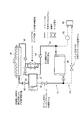
- FIG. 1 is a schematic configuration diagram of an engine waste heat utilization apparatus according to a first embodiment of the present invention.
- FIG. 2A is a schematic cross-sectional view of an expander pump in which the pump and the expander are integrated.
- FIG. 2B is a schematic cross-sectional view of the refrigerant pump.
- FIG. 2C is a schematic cross-sectional view of the expander.
- FIG. 3 is a schematic view showing the function of the refrigerant system valve.
- FIG. 4 is a schematic configuration diagram of the hybrid vehicle.
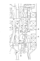
- FIG. 5 is a perspective view of the engine.
- FIG. 6 is a schematic view of the arrangement of the exhaust pipe as viewed from below the vehicle.
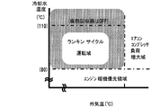
- FIG. 7A is a characteristic diagram of a Rankine cycle operation region.
- FIG. 7A is a characteristic diagram of a Rankine cycle operation region.
- FIG. 7B is a characteristic diagram of a Rankine cycle operation region.
- FIG. 8 is a timing chart showing a state when the hybrid vehicle is accelerated while assisting the rotation of the engine output shaft by the expander torque.
- FIG. 9 is a timing chart showing a state when the Rankine cycle system is restarted after being stopped.
- FIG. 10 shows the heat dissipation amount of the radiator when the Rankine cycle system is not operated and the clutch is not fixed, and the total heat dissipation amount of the radiator and the heat dissipation amount of the condenser when the Rankine cycle is not operated and the drive clutch is fixed. It is the figure which showed the relationship.
- FIG. 11 is a side view of the condenser and the radiator as viewed from the side of the vehicle.
- FIG. 12 is a characteristic diagram showing the relationship between the distance from the front of the vehicle and the air temperature.
- FIG. 13 is an engine operation region diagram for explaining the update of the boundary between the radiator performance NG region and the radiator performance OK region.
- FIG. 14A is a flowchart for explaining the update of the boundary between the radiator performance NG area and the radiator performance OK area.
- FIG. 14B is a flowchart for explaining the update of the boundary between the radiator performance NG area and the radiator performance OK area.
- FIG. 15 is a characteristic diagram of the heat dissipation amount of the condenser.
- FIG. 16 is a characteristic diagram of the total heat radiation capacity of the radiator and the condenser.
- FIG. 17 is a characteristic diagram of the outside air temperature correction coefficient.
- FIG. 18 is a characteristic diagram of the air conditioner load correction amount.
- FIG. 19 is an operation region map for explaining the update of the boundary between the radiator performance NG region and the radiator performance OK region.
- FIG. 20 is an operation region map for explaining the boundary between the radiator performance NG region and the radiator performance OK region when the outside air temperatures are different.
- FIG. 21 is a flowchart for explaining the limitation of the amount of supplied fuel.
- FIG. 22 is an operation region map after the boundary between the radiator performance NG region and the radiator performance OK boundary region is updated.
- FIG. 23 is a flowchart for explaining the operation of the engine waste heat utilization apparatus according to the second embodiment.
- FIG. 24 is a flowchart for explaining the operation of the engine waste heat utilization apparatus according to the third embodiment.
- FIG. 25 is a characteristic diagram of the engine maximum output.
- FIG. 19 is an operation region map for explaining the update of the boundary between the radiator performance NG region and the radiator performance OK region.
- FIG. 20 is an operation region map for explaining the boundary between the radiator
- FIG. 26 is a flowchart for explaining the operation of the engine waste heat utilization apparatus according to the fourth embodiment.
- FIG. 27 is a characteristic diagram of the basic maximum vehicle speed.
- FIG. 28 is a characteristic diagram of the outside air temperature correction coefficient.
- FIG. 29 is a schematic configuration diagram of an engine waste heat utilization device according to a fifth embodiment.
- FIG. 30 is a schematic configuration diagram of an engine waste heat utilization device according to a sixth embodiment.
- FIG. 1 is a schematic configuration diagram of an engine waste heat utilization apparatus according to a first embodiment of the present invention.
- the engine waste heat utilization device includes a Rankine cycle system 31.
- the Rankine cycle system 31 is configured to share the refrigerant and the condenser 38 with respect to the refrigeration cycle system 51.
- a system in which the Rankine cycle system 31 and the refrigeration cycle system 51 are integrated is referred to as an integrated cycle system 30.
- the integrated cycle system 30 circulates cooling water and exhaust in addition to a circuit in which the refrigerant of the Rankine cycle system 31 and the refrigeration cycle system 51 circulates, and components such as a pump, an expander, and a condenser provided in the circuit. It shall refer to the entire system including circuits.
- FIG. 4 is a schematic configuration diagram of the hybrid vehicle 1 on which the integrated cycle system 30 is mounted.
- the engine 2 In the hybrid vehicle 1, the engine 2, the motor generator 81, and the automatic transmission 82 are connected in series. The output of the automatic transmission 82 is transmitted to the drive wheels 85 via the propeller shaft 83 and the differential gear 84.
- a first drive shaft clutch 86 is provided between the engine 2 and the motor generator 81.
- the automatic transmission 82 includes a second drive shaft clutch 87 as a friction engagement element. The first drive shaft clutch 86 and the second drive shaft clutch 87 are connected to the engine controller 71, and the connection state is controlled according to the driving conditions of the hybrid vehicle 1. As shown in FIG.
- the hybrid vehicle 1 when the vehicle speed is in the EV traveling region where the efficiency of the engine 2 is poor, the engine 2 is stopped, the first drive shaft clutch 86 is shut off, and the second drive shaft clutch 87 is turned on. Connected, the hybrid vehicle 1 travels only with the driving force of the motor generator 81. On the other hand, when the vehicle speed deviates from the EV travel region and shifts to the Rankine cycle operation region, the engine 2 is operated and the Rankine cycle system 31 is set to the operation state.
- the engine 2 includes an exhaust passage 3.
- the exhaust passage 3 is composed of an exhaust manifold 4 and an exhaust pipe 5 connected to a collecting portion of the exhaust manifold 4.
- a bypass exhaust pipe 6 branches off from the exhaust pipe 5, and a waste heat recovery unit 22 for exchanging heat between the exhaust and the cooling water is provided in the exhaust pipe 5 in a section bypassed by the bypass exhaust pipe 6. Is provided.
- the waste heat recovery unit 22 and the bypass exhaust pipe 6 are integrated to form a waste heat recovery unit 23.
- the waste heat recovery unit 23 includes an underfloor catalyst 88 and a sub-muffler 89 downstream of the catalyst. It is arranged between.
- the cooling water that has flowed through these passages 13 and 14 is rejoined by a thermostat valve 15 that determines the distribution of the cooling water flow rate, and returns to the engine 2 via the cooling water pump 16.
- the cooling water pump 16 is driven by the engine 2 and its rotation speed is synchronized with the engine rotation speed.
- the bypass cooling water passage 14 that bypasses the radiator 11 is branched from the cooling water passage 13 and directly connected to the heat exchanger 36, and is branched from the cooling water passage 13 to waste heat recovery unit 22.
- the second bypass cooling water passage 25 connected to the heat exchanger 36 after passing through.
- the thermostat valve 15 increases the valve opening on the coolant passage 13 side, and relatively increases the amount of coolant passing through the radiator 11.
- the thermostat valve 15 reduces the valve opening on the cooling water passage 13 side and relatively reduces the amount of cooling water passing through the radiator 11.
- the cooling water temperature is particularly low, such as before the engine 2 is warmed up, the entire amount of the cooling water bypasses the radiator 11 and flows through the bypass cooling water passage 14.
- the valve opening on the bypass cooling water passage 14 side is not fully closed.
- the flow rate of the cooling water flowing through the radiator 11 increases, the flow rate of the cooling water flowing through the bypass cooling water passage 14 is lower than when the entire amount of cooling water flows through the bypass cooling water passage 14 side. However, it is configured so that the flow does not stop completely.
- a heat exchanger 36 for exchanging heat with the refrigerant of the Rankine cycle system 31 is provided in the bypass cooling water passage 14.
- the heat exchanger 36 is an integrated heater and superheater.
- two cooling water passages 36a and 36b are provided in approximately one row, and a refrigerant passage 36c through which the refrigerant of the Rankine cycle system 31 flows is provided adjacent to the cooling water passages 36a and 36b.
- Each passage 36a, 36b, 36c is configured such that the flow directions of the refrigerant and the cooling water are opposite to each other when the entire heat exchanger 36 is viewed from above.
- the cooling water passage 36 a located on the upstream side (left side in FIG. 1) for the refrigerant of the Rankine cycle system 31 is connected to the first bypass cooling water passage 24. Cooling water from the engine 2 is directly introduced into the left portion of the heat exchanger including the cooling water passage 36a, and the left portion of the heat exchanger functions as a heater for heating the refrigerant of the Rankine cycle system 31 flowing through the refrigerant passage 36c. .
- the cooling water passage 36 b located on the downstream side (right side in FIG. 1) for the refrigerant of the Rankine cycle system 31 is connected to the waste heat recovery device 22 via the second bypass cooling water passage 25. Cooling water that has passed through the waste heat recovery unit 22, that is, cooling water that has been overheated by the exhaust discharged from the engine 2, is introduced into the right side portion of the heat exchanger including the cooling water passage 36 b.
- the right part of the heat exchanger functions as a superheater that superheats the refrigerant flowing through the refrigerant passage 36c.
- the cooling water passage 22 a of the waste heat recovery unit 22 is provided adjacent to the exhaust pipe 5. By introducing the cooling water discharged from the engine 2 into the cooling water passage 22a of the waste heat recovery unit 22, the cooling water can be heated to, for example, about 110 to 115 ° C. by high-temperature exhaust.
- the cooling water passage 22a is configured such that the flow directions of the exhaust gas and the cooling water are opposite to each other when the entire waste heat recovery unit 22 is viewed from above.
- a control valve 26 is interposed in the second bypass cooling water passage 25 provided with the waste heat recovery unit 22.
- the cooling water temperature inside the engine 2 (engine water temperature) exceeds an allowable temperature (for example, 100 ° C.) for preventing deterioration of the efficiency of the engine 2 and knocking. So that the opening of the control valve 26 is reduced.
- the engine water temperature approaches the permissible temperature, the amount of cooling water passing through the waste heat recovery device 22 is reduced, so that it is possible to reliably prevent the engine water temperature from exceeding the permissible temperature.
- the exhaust pipe 5 includes a bypass exhaust pipe 6 that bypasses the waste heat recovery unit 22, and a thermostat valve 7 that controls the exhaust passage amount of the waste heat recovery unit 22 and the exhaust passage amount of the bypass exhaust pipe 6. And are provided.
- the thermostat valve 7 is disposed at a branch portion of the exhaust pipe 5.
- the valve opening of the thermostat valve 7 is based on the temperature of the cooling water exiting the waste heat recovery unit 22 so that the temperature of the cooling water exiting the waste heat recovery unit 22 does not exceed a predetermined temperature (for example, a boiling temperature of 120 ° C.). Adjusted.
- a predetermined temperature for example, a boiling temperature of 120 ° C.
- the heat exchanger 36, the thermostat valve 7 and the waste heat recovery unit 22 are integrated as a waste heat recovery unit 23.
- the waste heat recovery unit 23 is disposed in the middle of the exhaust pipe under the floor at the approximate center in the vehicle width direction.
- the thermostat valve 7 may be a relatively simple temperature sensing valve using bimetal or the like, or may be a control valve controlled by a controller based on a detection value of a temperature sensor. Since the adjustment of the heat exchange amount by the thermostat valve 7 involves a relatively large delay, if the thermostat valve 7 is adjusted alone, it is difficult to prevent the engine water temperature from exceeding the allowable temperature.
- control valve 26 of the second bypass cooling water passage 25 is controlled based on the engine water temperature, it is possible to quickly reduce the amount of heat recovery and reliably prevent the engine water temperature from exceeding the allowable temperature. it can. Further, if the engine water temperature is sufficiently lower than the allowable temperature, heat is generated until the temperature of the cooling water discharged from the waste heat recovery unit 22 reaches a temperature exceeding the allowable temperature of the engine water temperature (eg, 110 to 115 ° C.). Since the replacement is performed, the amount of waste heat recovered can be increased.
- the cooling water that has exited the cooling water passage 36 b joins the first bypass cooling water passage 24 via the second bypass cooling water passage 25.
- the Rankine cycle system 31 is configured as a part of the integrated cycle system 30 integrated with the refrigeration cycle system 51.
- Rankine cycle system 31 is a system that recovers waste heat of engine 2 into a refrigerant via cooling water of engine 2 and regenerates the recovered waste heat as power.
- the Rankine cycle system 31 includes a refrigerant pump 32, a heat exchanger 36, an expander 37, and a condenser 38.
- Each component of the Rankine cycle system 31 is connected by refrigerant passages 41 to 44 through which a refrigerant such as R134a circulates.
- the shaft 32a (rotary shaft) of the refrigerant pump 32 is connected to the output shaft of the expander 37 on the same shaft.
- the refrigerant pump 32 is driven by the output (power) generated by the expander 37, and the power generated by the refrigerant pump 32 is supplied to the output shaft (crankshaft) of the engine 2.
- the shaft 32 a of the refrigerant pump 32 and the output shaft of the expander 37 are arranged in parallel with the output shaft of the engine 2.
- a belt 34 is wound between a pump pulley 33 provided at the tip of a shaft 32 a of the refrigerant pump 32 and a crank pulley 2 a of the engine 2.
- the refrigerant pump 32 is a gear type pump as shown in FIG. 2B
- the expander 37 is a scroll type expander as shown in FIG. 2C.
- an electromagnetic drive clutch 35 (drive mechanism) is provided between the pump pulley 33 and the refrigerant pump 32.
- the drive clutch 35 is configured to be able to change the connection state between the refrigerant pump 32 and the expander 37 and the engine 2.
- the drive clutch 35 is connected when the output generated by the expander 37 exceeds the driving force or the like of the refrigerant pump 32 (when the predicted expander torque is positive), and the engine is generated by the output generated by the expander 37.
- the rotation of the second output shaft is assisted. By assisting the rotation of the output shaft of the engine 2 using the energy obtained by the waste heat recovery, the fuel consumption can be improved. Further, the energy for driving the refrigerant pump 32 that circulates the refrigerant can also be covered by the recovered waste heat.
- the refrigerant from the refrigerant pump 32 is supplied to the heat exchanger 36 via the refrigerant passage 41.
- heat exchanger 36 heat exchange is performed between the coolant of the engine 2 and the refrigerant, and the refrigerant is vaporized.
- the refrigerant discharged from the heat exchanger 36 is supplied to the expander 37 through the refrigerant passage 42.
- the expander 37 is a steam turbine that converts heat into rotational energy by expanding the vaporized and superheated refrigerant.
- the power recovered by the expander 37 drives the refrigerant pump 32 and is transmitted to the engine 2 via the drive clutch 35, the belt 34, and the like.
- the refrigerant discharged from the expander 37 is supplied to the condenser 38 via the refrigerant passage 43.
- the condenser 38 heat exchange is performed between the outside air and the refrigerant, and the refrigerant is cooled and liquefied.
- the condenser 38 and the radiator 11 are arranged in parallel, and the condenser 38 and the radiator 11 are configured to be cooled by the radiator fan 12.
- the refrigerant liquefied by the condenser 38 is guided to the refrigerant pump 32 through the refrigerant passage 44.
- the refrigerant guided to the refrigerant pump 32 is sent again to the heat exchanger 36 by the refrigerant pump 32.
- the refrigerant circulates in the Rankine cycle system 31.
- the refrigeration cycle system 51 shares the refrigerant of the Rankine cycle system 31, the configuration of the refrigeration cycle system 51 is simplified.
- the refrigeration cycle system 51 includes a compressor 52, a condenser 38, and an evaporator 55.
- the compressor 52 is a fluid machine that compresses the refrigerant of the refrigeration cycle system 51 to a high temperature and a high pressure, and is driven by the engine 2.
- a compressor pulley 53 is fixed to the drive shaft of the compressor 52, and a belt 34 is wound around the compressor pulley 53 and the crank pulley 2a.
- the driving force of the engine 2 is transmitted to the compressor pulley 53 via the belt 34, and the compressor 52 is driven.
- An electromagnetic compressor clutch 54 is provided between the compressor pulley 53 and the compressor 52.
- the compressor clutch 54 is configured to connect and disconnect the compressor 52 and the compressor pulley 53.
- the refrigerant discharged from the compressor 52 flows into the refrigerant passage 43 via the refrigerant passage 56 and is then supplied to the condenser 38.
- the condenser 38 is a heat exchanger that condenses and liquefies the refrigerant by heat exchange with the outside air.
- the refrigerant discharged from the condenser 38 is supplied to the evaporator 55 via the refrigerant passage 57 branched from the refrigerant passage 44.
- the evaporator 55 is provided in the case of the air conditioner unit together with the heater core.
- the evaporator 55 is a heat exchanger that evaporates the refrigerant from the condenser 38 and cools the conditioned air sent from the blower fan by latent heat of evaporation.
- the refrigerant evaporated by the evaporator 55 is returned to the compressor 52 through the refrigerant passage 58. Note that the mixing ratio of the conditioned air cooled by the evaporator 55 and the conditioned air heated by the heater core is adjusted to a temperature set by the occupant according to the opening of the air mix door.
- a plurality of valves are provided to control the refrigerant flowing in the cycle.
- a pump upstream valve 61 is provided in the refrigerant passage 44 connecting the refrigeration cycle branch point 45 and the refrigerant pump 32, and the refrigerant connecting the heat exchanger 36 and the expander 37.
- An expansion machine upstream valve 62 is provided in the passage 42.
- a check valve 63 is provided in the refrigerant passage 41 connecting the refrigerant pump 32 and the heat exchanger 36 to prevent the refrigerant from flowing back from the heat exchanger 36 to the refrigerant pump 32, and the expander 37 and the refrigeration cycle junction 46 are
- a check valve 64 is provided in the refrigerant passage 43 that connects the refrigerant passage 43 to prevent the refrigerant from flowing back from the refrigeration cycle junction 46 to the expander 37.
- the Rankine cycle system 31 also includes an expander bypass passage 65 that bypasses the expander 37 from the upstream side of the expander upstream valve 62 and merges upstream of the check valve 64, and the expander bypass passage 65 includes a bypass valve 66. Is provided.
- a pressure regulating valve 68 is provided in the passage 67 that bypasses the bypass valve 66.
- an air conditioner circuit valve 69 is provided in a refrigerant passage 57 that connects the refrigeration cycle branch point 45 and the evaporator 55. All of the four valves 61, 62, 66, and 69 described above are electromagnetic on-off valves.
- the engine controller 71 receives an expander upstream pressure signal detected by the pressure sensor 72, a refrigerant pressure Pd signal at the outlet of the condenser 38 detected by the pressure sensor 73, a rotation speed signal of the expander 37, and the like. The Based on these input signals, the engine controller 71 controls the compressor 52 and the radiator fan 12 of the refrigeration cycle system 51 according to the operating conditions, and valves 61, 62, 66, 69, etc. according to the operating conditions. Open / close control is performed.
- the controller 71 predicts the expander torque (regenerative power) based on the expander upstream pressure and the expander rotational speed, and assists the rotation of the engine output shaft when the predicted expander torque is positive.
- the drive clutch 35 is engaged.
- the controller 71 releases the drive clutch 35 when the predicted expander torque is zero or negative.
- the expander torque can be predicted with higher accuracy than when the expander torque (regenerative power) is predicted from the exhaust temperature. As a result, it is possible to appropriately engage and disengage the drive clutch 35 in accordance with the state of expansion machine torque generation. For details on this point, JP2010-190185A is helpful.
- the four on-off valves 61, 62, 66, 69 and the two check valves 63, 64 are refrigerant valves, and these valves will be described with reference to FIG.
- the pump upstream valve 61 is closed under a predetermined condition in which the refrigerant tends to be biased in the circuit of the Rankine cycle system 31 as compared with the circuit of the refrigeration cycle system 51, so that the refrigerant ( This is a valve for preventing the bias of the lubricating component).
- the pump upstream valve 61 closes the circuit of the Rankine cycle system 31 in cooperation with a check valve 64 disposed downstream of the expander 37.
- the expander upstream valve 62 is a valve for blocking the refrigerant passage 42 and increasing the refrigerant pressure to a predetermined pressure when the pressure of the refrigerant discharged from the heat exchanger 36 is relatively low. Thereby, even when the expander torque is not sufficiently obtained, the heating of the refrigerant is promoted, and for example, the time until the Rankine cycle system 31 is restarted (the time during which regeneration is possible) can be shortened.
- the bypass valve 66 is opened so that the refrigerant pump 32 can be operated by the refrigerant bypassing the expander 37 when the amount of refrigerant existing on the Rankine cycle system 31 side is not sufficient when the Rankine cycle system 31 is started. . Thereby, the starting time of Rankine cycle system 31 can be shortened. Since the refrigerant pump 32 is operated in a state where the refrigerant bypasses the expander 37, the refrigerant temperature at the outlet of the condenser 38 and the inlet of the refrigerant pump 32 has decreased to a predetermined value or more from the boiling point considering the pressure at those portions. In this case, it can be determined that a state in which sufficient liquid refrigerant can be supplied to the Rankine cycle 3 system 1 is ready.
- the check valve 63 disposed upstream of the heat exchanger 36 cooperates with the bypass valve 66, the pressure adjustment valve 68, and the expander upstream valve 62, and holds the refrigerant supplied to the expander 37 at a high pressure. Under the condition that the regeneration efficiency of the Rankine cycle system 31 is low, the operation of the Rankine cycle system 31 is stopped, and the circuit is closed over the front and rear sections of the heat exchanger 36. By raising the refrigerant pressure during the stop in this way, it becomes possible to restart the Rankine cycle system 31 quickly using the high-pressure refrigerant.
- the pressure regulating valve 68 opens when the pressure of the refrigerant supplied to the expander 37 becomes too high, and functions as a relief valve that releases the refrigerant that has become too high.
- the check valve 64 disposed downstream of the expander 37 cooperates with the pump upstream valve 61 to prevent the refrigerant from being biased toward the Rankine cycle system 31. If the engine 2 is not warmed immediately after the start of the operation of the hybrid vehicle 1, the Rankine cycle system 31 becomes cooler than the refrigeration cycle system 51, and the refrigerant may be biased toward the Rankine cycle system 31. In particular, immediately after the start of vehicle operation in summer, the cooling capacity is most demanded, so there is a demand for eliminating the uneven distribution of refrigerant and ensuring the cooling capacity.
- the check valve 64 is provided to prevent the refrigerant from being unevenly distributed on the Rankine cycle system 31 side.
- the compressor 52 has a structure in which refrigerant cannot freely pass when driving is stopped.
- the compressor 52 cooperates with the air conditioner circuit valve 69 to prevent the refrigerant from being biased toward the refrigeration cycle system 51.
- the refrigerant moves from the Rankine cycle system 31 side having a relatively high refrigerant temperature during steady operation to the refrigeration cycle system 51 side, and the refrigerant circulating in the Rankine cycle system 31 is changed. There may be a shortage.
- the temperature of the evaporator 55 is low immediately after the cooling is stopped, and the refrigerant tends to accumulate in the evaporator 55 having a low temperature and a relatively large volume.
- FIG. 5 is a perspective view of the engine 2 mounted on the vehicle. As shown in FIG. 5, the heat exchanger 36 is disposed vertically above the exhaust manifold 4 of the engine 2. By disposing the heat exchanger 36 in the space above the exhaust manifold 4, the mountability of the Rankine cycle system 31 to the engine 2 can be improved.
- the engine 2 is provided with a tension pulley 8 that applies a predetermined tension to the belt 34.
- FIG. 7A and 7B are operation region diagrams of the Rankine cycle system 31.
- FIG. FIG. 7A is an operation region diagram of Rankine cycle system 31 when the horizontal axis is the outside air temperature and the vertical axis is the engine water temperature (cooling water temperature).
- FIG. 7B is an operation region diagram of the Rankine cycle system 31 when the horizontal axis is the engine rotation speed and the vertical axis is the engine torque (engine load).
- the Rankine cycle system 31 is operated when predetermined Rankine cycle operation conditions are satisfied in FIGS. 7A and 7B.
- the operation of the Rankine cycle system 31 is stopped in a region on the low water temperature side where priority is given to warm-up of the engine 2 and a region on the high outside air temperature side where the load on the compressor 52 increases.
- the Rankine cycle system 31 is not operated, so that the coolant temperature is quickly raised.
- the Rankine cycle system 31 is stopped, sufficient refrigerant is provided to the refrigeration cycle system 51, and the cooling capacity is increased.
- the operation of the Rankine cycle system 31 is stopped in the EV travel region and the region on the high rotation speed side where the friction of the expander 37 increases. .
- the dimensions and the like of each part of the expander 37 are set such that the friction is small and the efficiency is high in the engine rotation speed range where the operation frequency is high.
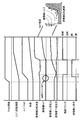
- FIG. 8 is a timing chart showing a state when the hybrid vehicle 1 is accelerated while assisting the rotation of the engine output shaft by the expander torque.
- an expander torque map showing how the operating state of the expander 37 changes during acceleration is shown.
- the expander torque becomes the largest in the portion where the expander rotational speed is low and the expander upstream pressure is high (upper left portion).
- the expander torque decreases as the expander rotational speed increases and the expander upstream pressure decreases (lower right side).
- the shaded area indicates a region where the expander torque becomes negative and the refrigerant pump 32 becomes a load on the engine.
- the constant speed running is continued until t1 when the driver steps on the accelerator pedal, and the expander 37 generates a positive torque.
- the rotation assist of the engine output shaft is performed by the expander torque.
- the rotation speed of the expander 37 that is, the rotation speed of the refrigerant pump 32 increases in proportion to the engine rotation speed, but the rises in the exhaust temperature and the cooling water temperature are delayed with respect to the increase in the engine rotation speed. . Therefore, the ratio of the recoverable heat amount to the refrigerant amount increased by the increase in the rotational speed of the refrigerant pump 32 is reduced. Therefore, even if the rotation speed of the expander increases, the refrigerant pressure upstream of the expander decreases and the expander torque decreases.
- the expander upstream valve 62 is switched from the open state to the closed state, for example, at time t2 when the expander torque becomes substantially zero. . Thereby, the phenomenon that the expander 37 is dragged to the engine 2 due to the decrease in the expander torque is avoided, and the deterioration of the regeneration efficiency is prevented.
- the drive clutch 35 is switched from the connected state (engaged state) to the disconnected state (released state).
- the refrigerant pressure upstream of the expander can be sufficiently reduced. Thereby, it is possible to prevent the expander 37 from over-rotating when the drive clutch 35 is disconnected.
- a large amount of refrigerant is supplied into the heat exchanger 36 by the refrigerant pump 32, and the Rankine cycle system 31 is smoothly restarted by effectively heating the refrigerant even when the Rankine cycle system 31 is stopped. .
- the expander upstream pressure rises again due to the increase in the heat dissipation of the engine 2.
- the expander upstream valve 62 is switched from the closed state to the open state, and the supply of the refrigerant to the expander 37 is resumed.
- the drive clutch 35 is connected again. By reconnecting the drive clutch 35, rotation assist of the engine output shaft by the expander torque is resumed.
- FIG. 9 is a timing immming chart showing a state in which the Rankine cycle system 31 is restarted in a mode different from FIG. 8 (control of t4) from the operation stop state in which the expander upstream valve 62 is closed and the drive clutch 35 is disconnected. It is.
- the heat release amount of the engine 2 increases, and the increase in the heat release amount increases the temperature of the cooling water flowing into the heat exchanger 36, and the temperature of the refrigerant in the heat exchanger 36.
- the expander upstream valve 62 is in the closed state, the refrigerant pressure upstream of the expander upstream valve 62, that is, the expander upstream pressure increases as the refrigerant temperature rises by the heat exchanger 36 (t11 to t12). ).
- This change in operating state switches the operating range of the engine 2 from the Rankine cycle non-operating range to the Rankine cycle operating range.
- the expander upstream valve 62 is not provided, when the shift to the Rankine cycle operation region is performed, the drive clutch 35 is immediately switched to the connected state and the expander 37 is coupled to the engine output shaft. A torque shock occurs due to the load on the engine 2.
- the expander upstream valve 62 when switching to the Rankine cycle operation region, the expander upstream valve 62 is not immediately switched from the closed state to the open state. That is, the closed state of the expander upstream valve 62 is continued even after shifting to the Rankine cycle operation region. Thereafter, the drive of the expander 37 is permitted at the timing t12 when the differential pressure between the expander upstream pressure and the expander downstream pressure becomes equal to or higher than a predetermined pressure, and the expander upstream valve 62 is switched from the closed state to the open state. In this way, when the expander upstream valve 62 is switched to the open state, a predetermined pressure of refrigerant is supplied to the expander 37, and the expander rotation speed rapidly increases from zero.
- the drive clutch 35 is switched from the disconnected state to the connected state at timing t13 when the expander rotational speed reaches the engine rotational speed. If the drive clutch 35 is connected before the expander 37 sufficiently increases the rotational speed, the expander 37 becomes an engine load and a torque shock occurs. On the other hand, by connecting the drive clutch 35 at t13 when there is no difference in rotational speed from the engine output shaft, the expander 37 is prevented from becoming an engine load, and the occurrence of torque shock is prevented.
- clutch sticking may occur.
- the engine 2 and the refrigerant pump 32 are always connected (refrigerant pump abnormality occurrence state), and the refrigerant pump 32 operates even when unnecessary.
- the drive clutch 35 is an electromagnetic clutch.
- the drive clutch 35 is brought into a clutch engagement state in which two members are engaged by generating electromagnetic force by energizing the solenoid coil, and the two members are separated by stopping energization of the solenoid coil and disappearing the electromagnetic force.
- the clutch is disengaged.
- the drive clutch 35 when a large slip input acts on the two members when the clutch is engaged, the two members may be seized and the clutch may be fixed. Further, in the drive clutch 35, the clutch can be stuck due to deterioration with time. Furthermore, since energization and de-energization of the solenoid is performed by the relay in the drive clutch 35, the clutch can be stuck even if a relay failure occurs.
- the refrigerant pump 32 When the clutch is fixed so that the engine 2 and the refrigerant pump 32 are always connected, the refrigerant pump 32 is always driven by the engine 2 as shown in FIG. Therefore, even though the operation region is the non-operation region of the Rankine cycle system 31, the Rankine cycle system 31 is substantially in an operation state, and the refrigerant 38 radiates heat in the condenser 38.
- the condenser 38 since the condenser 38 is disposed on the front surface of the radiator 11, the heat release of the coolant in the radiator 11 is inhibited by the heat release of the refrigerant in the condenser 38.
- the bar graph on the left side of FIG. 10 shows the heat radiation amount of the radiator 11 when the operating point is in the non-operating region of the Rankine cycle system 31 and the drive clutch 35 is not fixed.
- the bar graph on the right side of FIG. 10 shows the total amount of heat released from the radiator 11 and the condenser 38 when the operating point is in the non-operating region of the Rankine cycle system 31 and the drive clutch 35 is stuck.
- the time when the drive clutch 35 is not fixed is referred to as “when the clutch is not fixed”
- the time when the drive clutch 35 is fixed is referred to as “when the clutch is fixed”.
- the Rankine cycle non-operation area is abbreviated as “Rankine non-operation area”.
- the total heat dissipation amount of the radiator 11 and the condenser 38 when the clutch is fixed is lower than the heat dissipation amount of the radiator 11 when the clutch is not fixed. This is a matter that the present inventors have found for the first time. Since the heat of the refrigerant is radiated by the condenser 38 of the Rankine cycle system 31 and the heat of the cooling water is radiated by the radiator 11 when the clutch is fixed, the total amount of heat radiated from the condenser 38 and radiator 11 is It is likely to coincide with the heat dissipation amount of the radiator 11 when not fixed.
- the total heat dissipation amount of the radiator 11 and the condenser 38 when the clutch is fixed is lower than the heat dissipation amount of the radiator 11 when the clutch is not fixed. This is because the flow rate of the refrigerant circulating through the Rankine cycle system 31 is limited, and the heat radiation amount of the condenser 38 is limited, and the heat radiation efficiency of the radiator 11 deteriorates due to the heat radiation of the condenser 38. This is probably because of this.
- FIG. 11 is a view of the condenser 38 and the radiator 11 arranged on the front surface of the vehicle 1 as viewed from the side of the vehicle.
- the condenser 38 is disposed in front of the radiator 11.
- the traveling wind passes from the front side of the vehicle in the order of the condenser 38 and the radiator 11 and flows toward the rear of the vehicle.
- the refrigerant flowing through the condenser 38 and the cooling water flowing through the radiator 11 are higher than the outside air, the heat of the refrigerant is radiated by the condenser 38 and the heat of the cooling water is radiated by the radiator 11, so the condenser 38 and the radiator When passing through 11, the temperature of the traveling wind rises.
- FIG. 12 is a characteristic diagram showing the temperature change of the air passing through the condenser 38 and the radiator 11 as shown in FIG.
- the horizontal axis represents the distance from the front of the vehicle.
- the condenser 38 is located between the predetermined value a and the predetermined value b at a distance from the front surface of the vehicle, and the radiator 11 is located between the predetermined value c and the predetermined value d.
- the solid line in FIG. 12 shows the change in air temperature when the Rankine cycle is not operating and when the clutch is not locked.
- the condenser 38 does not radiate heat, so the air temperature remains at the outside air temperature T1 until the distance from the vehicle front surface reaches the predetermined value c.
- the temperature of the air rises linearly when the distance from the front of the vehicle is between the predetermined value c and the predetermined value d, and the predetermined temperature T4 become.
- the temperature of the air does not rise any further, so that after the predetermined value d, it remains at the predetermined temperature T4.
- the broken line in FIG. 12 shows the change in the air temperature when the Rankine cycle is not operating and the clutch is fixed.
- the Rankine cycle system 31 is operated due to the clutch being fixed, so that the refrigerant radiates heat in the condenser 38. Therefore, when the air passes through the condenser 38, the air receives heat from the condenser 38, and therefore, the air temperature is changed from the outside air temperature T1 to the predetermined temperature T2 when the distance from the vehicle front is between the predetermined value a and the predetermined value b. To rise. The temperature of the air that has passed through the condenser 38 does not rise until it reaches the radiator 11.
- the air receives heat from the radiator 11, so that the temperature of the air rises linearly when the distance from the front of the vehicle is between the predetermined value c and the predetermined value d, and the predetermined temperature T3 become.
- the temperature rise when passing through the radiator 11 is smaller than that in the Rankine cycle non-operating region and when the clutch is not fixed, the temperature of the air after passing through the radiator 11 reaches only a predetermined temperature T3 lower than the predetermined temperature T4. .
- the temperature of the air leaving the radiator 11 is lower when the clutch is fixed than when the clutch is not fixed.
- the air side heat radiation amount Q of the radiator 11 is obtained by the equation (1).
- the condenser 38 dissipates heat when the Rankine cycle is not operating and the clutch is fixed, the air temperature Ta on the front surface of the radiator 11 rises, so that the difference between the radiator inlet cooling water temperature Tw and the radiator front air temperature Ta is as shown in FIG. Get smaller. If it does so, according to said (1) Formula, the air side heat radiation amount Q of a radiator will fall rather than the case where the condenser 38 does not radiate heat. This means that when air passes through the radiator 11, the inclination of the temperature rise of the air when the Rankine cycle is not operating and when the clutch is fixed is smaller than that when the Rankine cycle is not operating and when the clutch is not fixed. means. Therefore, when the difference between the radiator inlet cooling water temperature Tw and the radiator front air temperature Ta becomes small due to the influence of the heat radiation of the condenser 38, the heat radiation efficiency of the radiator 11 deteriorates.
- the controller 71 limits the engine operating range when the Rankine cycle is not operated and the clutch is fixed, as compared to when the Rankine cycle is not operated and the clutch is not fixed.
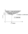
- FIG. 13 is an engine operation region diagram in which the horizontal axis represents the engine rotation speed and the vertical axis represents the engine torque.
- a thin line at the lower right that is drawn substantially in parallel is an engine heat dissipation amount line (equal engine output line), and the upper right thin line indicates that the engine heat dissipation amount is larger (the engine output becomes higher).
- the heat dissipation efficiency of the radiator 11 is worse than when the clutch is not fixed, and the radiator performance NG region is substantially increased to the position of the one-dot chain line as shown in FIG. Enlarge. That is, the radiator performance OK region is substantially narrowed.
- the radiator performance OK region is substantially narrowed.
- the Rankine cycle non-operating area when the operating point is in the region sandwiched between the thick line and the one-dot chain line, what was in the radiator performance OK area when the clutch is not fixed is in the radiator performance NG area when the clutch is fixed, Overheating can occur.
- the heat radiation performance component that inhibits the heat radiation of the radiator 11 due to the heat radiation of the condenser 38 when the clutch is fixed is converted into the engine output, and the engine torque obtained from the converted engine output is a predetermined value. Calculate as A. Then, the boundary between the radiator performance NG region and the radiator performance OK region is moved downward in FIG. 13 by a predetermined value A to expand the radiator performance NG region and narrow the radiator performance OK region.
- FIG. 13 shows three load / load lines B, C, and D.
- Line B is a road / load line when the vehicle is driven at a constant vehicle speed of 40 km / h.
- Line C is a road / load line for driving a vehicle at a constant 60 km / h
- line D is a road / load line for driving a vehicle at a constant 80 km / h.
- the point E which is the intersection of the downwardly protruding thick line and line B is the radiator performance OK range (engine operating range) It becomes the limit. That is, the engine rotational speed G at point E becomes the maximum engine rotational speed, and the engine torque I at point E becomes the maximum engine torque.
- the boundary between the two areas shifts from the thick line to the one-dot chain line when the Rankine cycle non-operating area and the clutch are fixed.
- the point F that is the intersection of the alternate long and short dash line and the line B is the limit of the radiator performance OK region. That is, the engine rotational speed H at point F becomes the maximum engine rotational speed, and the engine torque J at point F becomes the maximum engine torque.
- the maximum rotational speed decreases from G to H, and the maximum engine torque decreases from I to J.
- 14A and 14B show the control for updating the boundary between the two regions so that the radiator performance NG region is expanded and the radiator performance OK region is narrowed when the Rankine cycle is not operated and the clutch is fixed.
- This control is repeatedly executed at a constant time period (for example, a period of 10 milliseconds).
- step 1 the controller 71 determines whether or not the operating point of the engine 2 is in the Rankine cycle non-operating region.
- 7A and 7B the operating range of the Rankine cycle system 31 has been described, but the remaining operating range excluding the operating range of the Rankine cycle system 31 is the Rankine cycle non-operating range.
- the reason for being in the Rankine cycle non-operating region is that overheating may occur in the Rankine cycle non-operating region.
- the controller 71 determines in step 2 whether or not the drive clutch 35 is in the clutch-fixed state.
- Whether the drive clutch 35 is stuck or not is determined based on a pump shaft rotational speed sensor 75 (see FIG. 1) that detects the rotational speed of the shaft 32a of the refrigerant pump 32. By stopping energization of the solenoid coil in the Rankine cycle non-operating region, the drive clutch 35 is released. Therefore, when the shaft 32a of the refrigerant pump 32 is rotating even in the Rankine cycle non-operating region, it can be determined that the clutch is stuck.
- the controller 71 determines that the drive clutch 35 is stuck. Information (determination result) on whether or not the drive clutch 35 is stuck is stored in the memory of the controller 71. If the drive clutch 35 is not fixed, the controller 71 ends the current process.
- the processes in steps 3 to 16 are processes for expanding the radiator performance NG area and narrowing the radiator performance OK area.
- step 3 the heat release amount Pcond [kW] of the condenser 38 when the Rankine cycle is not operated and the clutch is fixed is calculated.
- the heat release amount Pcond of the condenser 38 is calculated on the basis of the Rankine cycle non-operating region and the refrigerant flow rate when the clutch is fixed, the refrigerant pressure / temperature, and the vehicle speed.
- the heat release amount Pcond of the condenser 38 increases as the vehicle speed VSP increases, as shown in FIG. .
- the vehicle speed is detected by a vehicle speed sensor 79 (see FIG. 1).
- the controller 71 executes step 4.
- the controller 71 searches a table having the contents shown in FIG. 16 based on the heat radiation amount Pcond of the condenser 38, and the total heat radiation capacity Ptotl [kW] of the radiator 11 and the condenser 38 when the Rankine cycle is not operated and the clutch is fixed. Is calculated.
- the heat radiation capability Ptotl decreases as the heat radiation amount Pcond of the condenser 38 increases.
- the characteristics of FIG. 16 represent a decrease in the total heat dissipation capability of the radiator 11 and the condenser 38 due to the heat dissipation inhibition in the radiator 11 described in FIG.
- the characteristic of FIG. 16 also indicates that the ratio of the heat dissipation of the radiator 11 is increased as the heat dissipation amount of the condenser 38 is increased.
- step 5 the controller 71 divides the actual engine output Peng [kW] by the heat release amount Prad [kW] of the radiator 11 according to the equation (2) to calculate a conversion coefficient K [unknown number] for the engine output.
- the actual engine output Peng on the right side of equation (2) and the heat release amount Prad of the radiator 11 are values when the Rankine cycle is not operated and the clutch is fixed.
- the actual engine output Peng is calculated based on the intake air amount Qa detected by the air flow meter 76 (see FIG. 1).
- the heat dissipation amount Prad of the radiator 11 is calculated based on the Rankine cycle non-operating region and the coolant flow rate when the clutch is fixed, the coolant pressure / temperature, and the vehicle speed.
- Step 6 the controller 71 multiplies the engine output conversion coefficient K and the total heat dissipation capability Ptotl by the equation (3), and calculates the engine output ⁇ Peng0 [kW], which is the basic heat dissipation decrease corresponding to the Rankine cycle non-operating range and the clutch being fixed. Is calculated.
- the coefficient K is smaller than 1.0 from the equation (2), and ⁇ Peng0 from the equation (3). Is corrected to the decreasing side.
- the actual engine output Peng is smaller than the radiator heat dissipation amount Prad when the Rankine cycle is not operated and the clutch is fixed, there is a margin in the heat dissipation of the radiator 11. In this case, by correcting ⁇ Peng0 to the decreasing side, it is avoided that the radiator performance OK region is set unnecessarily narrow.
- K is a coefficient for reflecting the relationship between the actual engine output Peng and the heat dissipation amount Prad of the radiator 11 in the engine output corresponding to the decrease in the heat dissipation amount when the Rankine cycle is not operated and the clutch is fixed.
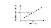
- step 7 the controller 71 calculates an outside air temperature correction coefficient Kair1 [unnamed number] by searching a table having the contents shown in FIG. 17 from the outside air temperature Tair detected by the outside air temperature sensor 77 (see FIG. 1). .
- Step 8 the controller 71 multiplies the outside air temperature correction coefficient Kair1 and ⁇ Peng0 by the equation (4) to calculate a target heat radiation amount reduction equivalent engine output ⁇ Peng [kW] when the Rankine cycle is not operating and the clutch is fixed.
- the outside air temperature correction coefficient Kair1 is 1.0 when the outside air temperature Tair0 at the time of adaptation (initial setting) is 1 and is 1 when the actual outside air temperature Tair is higher than the outside air temperature Tair0 at the time of adaptation.
- a value greater than 0.0 The reason why ⁇ Peng0 is corrected to increase when the actual outside air temperature is higher than the outside air temperature at the time of adaptation is that overheating is more likely to occur when the actual outside air temperature is higher than the outside air temperature at the time of adaptation.
- the outside air temperature correction coefficient Kair1 becomes a value smaller than 1.0. This is because overheating is less likely to occur when the actual outside air temperature is lower than the outside air temperature at the time of adaptation, and ⁇ Peng0 can be corrected to the reduction side accordingly.
- step 9 the controller 71 calculates the basic torque margin Marg0 [N ⁇ m] by dividing the target heat radiation reduction conversion engine output ⁇ Peng by the engine rotational speed Ne at that time according to the equation (5).
- the basic torque margin in the equation (5) is an amount by which the boundary between the radiator performance NG region and the radiator performance OK region is moved to the engine torque decreasing side.
- the boundary between the radiator performance NG region and the radiator performance OK region is expanded by a predetermined value A toward the engine torque decreasing side, but the basic torque margin Marg0 is a value corresponding to the predetermined value A.
- the controller 71 determines whether or not there is an air conditioner load.
- the compressor 52 for the air conditioner is driven by the engine 2. Therefore, when there is an air conditioner load, the compressor clutch 54 is in a connected state, and the compressor 52 and the engine 2 are connected. It is connected via a compressor clutch 54.
- the compressor clutch 54 is an electromagnetic clutch, and is connected when an ON signal is received, and is disconnected when an OFF signal is received.
- the controller 71 determines the presence or absence of an air conditioner load based on the ON / OFF signal to the compressor clutch 54. That is, when the signal to the compressor clutch 54 is an ON signal, the controller 71 determines that there is an air conditioner load, and executes the processing from step 11 onward.
- Steps 11 to 13 are processes for correcting the basic torque margin Marg0 to the increase side when there is an air conditioner load.
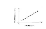
- the controller 71 calculates the air conditioner load Laircon.
- the air conditioner load Laircon include a set temperature and the number of passengers.
- the air conditioner load Laircon is set to zero when the actual set temperature is the set temperature at the time of adaptation (initial setting) or when the actual number of passengers matches the number of passengers at the time of adaptation (initial setting).
- the air conditioner load Laircon is set to a larger positive value as the actual set temperature is lower than the set temperature at the time of adaptation or as the actual number of occupants is greater than the number of occupants at the time of adaptation.
- Step 12 the controller 71 calculates an air conditioner load correction amount Haircon [N ⁇ m] by searching a table having the contents shown in FIG. 18 from the air conditioner load Laircon.
- the controller 71 calculates the target torque margin Marg [N ⁇ m] by adding the air conditioner load correction amount Haircon and the basic torque margin Marg0 using equation (6).
- the air conditioner load correction amount Haircon increases as the air conditioner load Laircon increases. Therefore, the target torque margin Marg increases as the air conditioner load Laircon increases.
- the boundary between the radiator performance NG region and the radiator performance OK region when the air conditioner load is present is updated to the engine torque decreasing side as compared with the case where there is no air conditioner load. That is, the radiator performance NG area is expanded and the radiator performance OK area is narrowed. This is because the load on the engine 2 is greater when there is an air conditioner load than when there is no air conditioner load, and the cooling water temperature rises and the engine 2 is more likely to overheat. Therefore, the radiator performance NG range is expanded accordingly. This is to narrow the radiator performance OK region.
- step 10 determines that the signal to the compressor clutch 54 is an OFF signal
- the controller 71 determines that there is no air conditioner load, and executes the process of step 14.
- the controller 71 sets the basic torque margin Marg0 as it is to the target torque margin Marg.
- Steps 15 and 16 are processes for updating the boundary between the radiator performance NG area and the radiator performance OK area using the target torque margin Marg calculated as described above.
- step 15 the controller 71 reads the operation region map of the engine 2.
- FIG. 19 is an example of the read driving region map.
- an area map including this boundary is stored in the ROM or the like. It is remembered.
- an area map stored at the time of vehicle shipment from the factory is read out.
- the controller 71 uses the target torque margin Marg to update the boundary between the radiator performance NG region and the radiator performance OK region to the engine torque decreasing side, and stores the updated region map. For example, when the boundary between the updated radiator performance NG region and the radiator performance OK region becomes a one-dot chain line shown in FIG. 19, a region map including the updated boundary is stored as a new engine operation region map.
- the area map at the time of factory shipment shown in FIG. 19 is a case where the actual outside air temperature matches the outside air temperature at the time of adaptation.
- FIG. 20 when the actual outside air temperature is different from the outside air temperature at the time of adaptation, particularly when the actual outside air temperature is higher than the outside air temperature at the time of adaptation, the boundary between the radiator performance NG area and the radiator performance OK area The change will be described.
- the boundary between the radiator performance NG region and the radiator performance OK region is in the position of the solid line when the outside air temperature at the time of adaptation is 20 ° C. and the Rankine cycle non-operation region and the clutch is not fixed.
- the boundary between the radiator performance NG region and the radiator performance OK region moves to the position of the one-dot chain line in order to suppress overheating when the clutch is locked even in the Rankine cycle non-operating region.
- the boundary between the radiator performance NG region and the radiator performance OK region becomes higher as the actual outside air temperature becomes higher than 25 ° C, 30 ° C, 40 ° C from the outside air temperature at the time of adaptation.
- the radiator performance NG region is expanded and the radiator performance OK region is narrowed as the actual outside air temperature is higher than the outside air temperature at the time of adaptation. This is because the radiator 11 is less likely to dissipate heat as the actual outside air temperature is higher than the adapted outside temperature, and overheating is more likely to occur than at the adapted outside temperature, and the radiator performance NG region needs to be expanded accordingly. It is.
- the boundary of the operation region of the engine 2 is determined by the maximum fuel supply amount, the maximum throttle valve opening, the maximum engine speed, and the like. Therefore, in order to operate the engine 2 in the narrower radiator OK region, the amount of supplied fuel should be reduced so that it returns to the boundary of the narrower radiator OK region when the operating point belongs to the enlarged radiator performance NG region. Good. Instead of the supplied fuel amount, the throttle valve opening, the engine speed, and the like may be decreased.
- a method of operating the engine 2 in a narrow radiator OK region by reducing the amount of supplied fuel will be described.
- FIG. 21 is a flowchart showing control for reducing the amount of supplied fuel when the operating point determined from the engine torque and the engine rotation speed belongs to the radiator performance NG region. This control is repeatedly executed at a constant time period (for example, a period of 10 milliseconds).
- the engine 2 is a gasoline engine.
- Steps 21 and 22 the controller 71 determines whether or not the Rankine cycle is not operating and whether or not the clutch is locked. If it is not in the Rankine cycle non-operating range, or if it is not in the Rankine cycle operating range and the clutch is not locked, the controller 71 ends the current control.
- step 23 the controller 71 calculates a basic fuel supply amount Qf0.
- a fuel injection valve is provided in an intake port or a combustion chamber, and fuel at a predetermined pressure is supplied by opening the fuel injection valve at a predetermined timing.
- the fuel pressure is constant, the period during which the fuel injection valve is open (injection pulse width) is proportional to the amount of fuel supplied. Therefore, in the engine 2, the basic injection pulse width is based on the intake air amount Qa detected by the air flow meter 76 (see FIG. 1) and the engine rotational speed Ne detected by the crank angle sensor 78 (see FIG. 1). Tp [ms] is calculated. This basic injection pulse width Tp is used as the basic fuel supply amount Qf0.
- step 24 the controller 71 multiplies the intake air amount Qa detected by the air flow meter 76 (see FIG. 1) by the conversion coefficient C2 according to the equation (7), and calculates the actual Rankin cycle non-operating range and the actual state when the clutch is fixed. Engine output Peng [kW] is calculated.
- step 25 the controller 71 divides the actual engine output Peng [kW] by the engine speed Ne at that time according to the equation (8), and calculates the actual engine torque Torq [ N ⁇ m] is calculated.
- Torq C1 ⁇ Peng / Ne (8)
- Step 26 the controller 71 determines whether the operating point determined from the actual engine torque Torq and the actual engine operating rotational speed Ne when the clutch is locked and the Rankine cycle non-operating region belongs to the radiator performance NG region on the operating region map. Determine whether or not.
- the operation region map used here is an operation region map in which the boundary between the radiator performance NG region and the radiator performance OK boundary region is updated as shown in FIG.
- the operating point determined by Torq1 and Ne1 when the Rankine cycle is not operated and the clutch is fixed, the operating point determined by Torq1 and Ne1. Becomes the L point in the enlarged radiator performance NG region.
- overheating may occur. In order to suppress overheating, it is necessary to move the operating point to the position of the alternate long and short dash line that is the boundary between the radiator performance OK region and the radiator performance OK region.
- the engine torque is reduced toward the M point, or the engine torque and the engine speed are reduced toward the N point. You may be allowed to.
- the amount of supplied fuel is decreased, and therefore the engine torque is decreased toward the point M in FIG.
- the controller 71 executes the processing of steps 27 to 29 in FIG. 21 in order to move the operating point from the L point to the M point.
- Steps 27 to 29 are processes for returning the operating point to the boundary of the radiator performance OK region by decreasing the amount of supplied fuel when the operating point belongs to the radiator performance NG region.
- step 27 the controller 71 calculates a maximum torque Tmax at the engine rotation speed Ne1 at that time by searching a region map having the contents shown in FIG. 22 from the engine rotation speed Ne1.
- the maximum torque Tmax is the following value. That is, in the operation region map of FIG. 22, a vertical line is drawn from the predetermined value Ne1 toward the boundary between the radiator performance NG region and the radiator performance OK region, and a lead line is drawn to the left from the point where the vertical line intersects the boundary. The engine torque at the position where the lead line intersects the vertical axis is the maximum torque Tmax.
- step 28 the controller 71 calculates the supplied fuel decrease amount Hgen1 by the equation (9) based on the difference between the actual engine torque Torq1 at point L and the maximum torque Tmax with respect to the engine rotational speed Ne1 at point L.
- Hgen1 C3 ⁇ (Torq ⁇ Tmax) (9)
- C3 Conversion factor for engine torque
- step 29 the controller 71 calculates a target supply fuel amount mQf by subtracting the supply fuel decrease amount Hgen1 from the basic supply fuel amount Qf0 according to equation (10).
- the reason why the amount of fuel supplied is reduced by the equation (10) is to reduce the torque generated in the engine 2 and move the operating point to the engine torque decreasing side in the operating region map of FIG.
- the controller 71 calculates the supply fuel decrease amount Hgen1 of equation (9) in the same unit [ms] as the basic injection pulse width Tp. Assuming that the supplied fuel decrease amount calculated in this way is Hgen1 ′, a value obtained by subtracting Hgen1 ′ from the basic injection pulse width Tp becomes the corrected basic injection pulse width HTp, and the fuel injection pulse width Ti is calculated according to the known equation (11). [Ms] can be calculated. This fuel injection pulse width Ti is used as the target supply fuel amount mQf.
- step 30 the controller 71 executes the process of step 30 because it is not necessary to limit the amount of fuel supplied.
- the controller 71 sets the basic supply fuel amount Qf0 as it is as the target supply fuel amount mQf.
- the controller 71 calculates the fuel injection pulse width Ti [ms] using the basic injection pulse width Tp according to the equation (12). This fuel injection pulse width Ti is used as the target supply fuel amount mQf.
- the controller 71 outputs the target supply fuel amount mQf calculated as described above to the fuel supply device.
- the controller 71 controls the fuel injection valve so that the fuel injection valve as the fuel supply device is opened with the calculated fuel injection pulse width Ti.
- the inventors have determined that the amount of heat released from the radiator 11 when the Rankine cycle is not operating and when the clutch is not locked (when the refrigerant pump is not abnormal) is higher than when the Rankine cycle is not operating and when the clutch is locked (the refrigerant pump is abnormal). It was found that the amount of heat released from the radiator 11 and the condenser 38 at the same time was reduced. For this reason, when the Rankine cycle is not operated and the clutch is fixed, the temperature of the engine cooling water rises by the amount of heat radiation that is different from that when the Rankine cycle is not operated and the clutch is not fixed, and the engine 2 is overheated depending on the operating point. There is a fear. *
- the waste heat utilization apparatus of the present embodiment is powered by using the radiator 11 that cools the cooling water of the engine 2, the heat exchanger 36 that recovers the waste heat of the engine 2 to the refrigerant, and the refrigerant discharged from the heat exchanger 36.
- the Rankine cycle system 31 in which the condenser 38 and the radiator 11 are arranged in order, and a drive mechanism such as a drive clutch 35 that drives the refrigerant pump 32 are provided.
- the controller 71 (operating region limiting means) operates when the Rankine cycle is not operating and the clutch is locked (when the refrigerant pump is abnormal), and when the Rankine cycle is not operating and the clutch is not fixed (the refrigerant pump is not abnormal). ),
- the radiator performance OK region engine operation region
- the radiator performance OK region is limited (see steps 1 to 9 in FIG. 14A, steps 10, 14, 15, 16, and FIG. 19 in FIG. 14B).
- the controller 71 performs the radiator performance OK by the basic heat radiation amount decrease equivalent conversion engine output ⁇ Peng0 (the value obtained by converting the heat radiation decrease amount in which the heat radiation of the radiator 11 is inhibited by the heat radiation of the condenser 38 as the engine output).
- the area is narrowed (see steps 3 to 9 in FIG. 14A, steps 10, 14, 15, 16, and FIG. 19 in FIG. 14B). Thereby, generation
- the heat dissipation performance of the radiator 11 decreases as the outside air temperature Tair is higher than the outside air temperature Tair0 at the time of adaptation.
- the controller 71 narrows the radiator performance OK region as the outside air temperature Tair is higher (Steps 7, 8, 9 in FIG. 14A, Steps 10, 14, 15, 16, FIG. FIG. 20). Thereby, even if the outside temperature Tair becomes higher than the outside temperature Tair0 at the time of adaptation, the occurrence of overheating can be suppressed.
- the controller 71 narrows the radiator performance OK region when the air conditioner load acts on the engine 2 than when the air conditioner load does not act (steps 10, 11, 12, 13, and FIG. 14B). 15, 16). Thereby, generation
- FIG. 23 is a flowchart showing control for restricting the air conditioner operation. This control is repeatedly executed at a constant time period (for example, a period of 10 milliseconds).
- Steps 41 and 42 the controller 71 determines whether or not it is in the Rankine cycle non-operation region, and determines whether or not the clutch is locked. If it is not the Rankine cycle non-operating range, or if it is not the Rankine cycle operating range and the clutch is not locked, the controller 71 ends the current process.
- the controller 71 determines in step 43 whether or not the air conditioner is operating. This determination is made based on the state of the air conditioner switch and the compressor clutch 54. The controller 71 determines that the air conditioner is not operating, for example, when the air conditioner switch is OFF.
- the controller 71 ends the current process. On the other hand, if the air conditioner switch is ON and the air conditioner is operating, the controller 71 increases the temperature in the vehicle compartment by a predetermined value in step 44.
- the compressor clutch 54 is driven and controlled based on the ON duty signal from the controller 71.
- the ON duty is increased, the connection ratio of the clutch 54 per fixed time increases relatively, and the compressor 52 works well.
- the ON duty is decreased, the connection ratio of the clutch 54 per fixed time is relatively decreased, and the function of the compressor 52 is deteriorated.
- the ON duty is set larger as the blowing temperature is lower. This is because when the blowout temperature is low, the ON duty is made larger than when the blowout temperature is high, the connection ratio of the clutch 54 per fixed time is increased, and the compressor 52 works well. In this way, the load on the engine 2 increases as the compressor 52 works better, so the coolant temperature rises.
- the connection ratio of the clutch 54 per fixed time is relatively reduced. Therefore, the load on the engine 2 is reduced by the reduction in the clutch 54 connection ratio, and the occurrence of overheating can be more reliably suppressed.
- the engine load may be reduced. Therefore, during the air conditioner operation, the air volume of the blower that sends cool air into the passenger compartment may be reduced by a predetermined value.
- the power source of the motor that drives the blower is a battery, and the battery stores the electric power obtained by the engine-driven alternator.
- the SOC (State of Charge) of the battery decreases earlier, and the alternator is driven by the engine 2 to compensate for this. That is, when the blower air volume is large, the load on the engine 2 becomes larger than when the blower air volume is small. Therefore, by reducing the blower air volume by a predetermined value during the air conditioner operation, the load on the engine 2 can be reduced, and the occurrence of overheating can be more reliably suppressed.
- the controller 71 air conditioner operation control means
- the controller 71 increases the blowing temperature in the passenger compartment by a predetermined value or decreases the blower air volume by a predetermined value. Or restricting the air conditioner operation. By limiting the air conditioner operation in this way, the chance of overheating can be reduced.
- FIG. 24 replaces the flowcharts of FIGS. 14A, 14B, and 21 in the first embodiment.
- the control shown in FIG. 24 is repeatedly executed at a constant time period (for example, a period of 10 milliseconds).
- a constant time period for example, a period of 10 milliseconds.
- the engine operation range is limited when the Rankine cycle non-operation range and the clutch are fixed.
- the engine maximum output is limited when the Rankine cycle is not operated and the clutch is fixed. That is, the controller 71 calculates the engine maximum output Pmax when the Rankine cycle is not operated and the clutch is fixed. If the output of the engine 2 exceeds the engine maximum output Pmax, the output of the engine 2 is reduced to the engine maximum output Pma. Decrease.
- step 6 the controller 71 calculates the engine output ⁇ Peng0 corresponding to the decrease in basic heat dissipation when the Rankine cycle is not operated and the clutch is fixed. Thereafter, in step 51, the controller 71 retrieves the engine maximum output Pmax [kW] when the Rankine cycle is not operated and the clutch is fixed by searching a table having the contents shown in FIG. calculate.
- the engine maximum output Pmax0 decreases as ⁇ Peng0 increases. This is because overheating is more likely to occur as ⁇ Peng0 is larger, and the engine maximum output needs to be reduced accordingly.
- ⁇ Peng0 is zero when the Rankine cycle is not operating and the clutch is not locked. That is, in FIG. 25, the engine maximum output Q when ⁇ Peng0 is zero is the engine maximum output when the Rankine cycle is not operating and when the clutch is not locked (normal operation).
- step 52 the controller 71 compares the actual engine output Peng with the engine maximum output Pmax when the Rankine cycle is not operated and the clutch is fixed. If the actual engine output Peng exceeds the engine maximum output Pmax when the Rankine cycle is not operated and the clutch is fixed, overheating may occur. In this case, in order to decrease the actual engine output Peng to the engine maximum output Pmax, the controller 71 executes the processes of steps 53 and 54.
- step 53 the controller 71 calculates the supply fuel decrease amount Hgen2 based on the difference between the actual engine output Peng and the engine maximum output Pmax by the equation (13).
- Hgen2 C4 ⁇ (Peng ⁇ Pmax) (13)
- C4 Conversion factor to the amount of fuel supplied
- step 54 the controller 71 calculates a target supply fuel amount mQf by subtracting the supply fuel decrease amount Hgen2 from the basic supply fuel amount Qf0 according to equation (14).
- the controller 71 sets the basic supply fuel amount Qf0 as the target supply fuel amount mQf in step 30.
- the controller 71 outputs the target supply fuel amount mQf calculated as described above to the fuel supply device.
- the controller 71 (maximum engine output limiting means) operates when the Rankine cycle is not operating and the clutch is locked (when the refrigerant pump is abnormal), when the Rankine cycle is not operating and when the clutch is not locked (refrigerant pump).
- the engine maximum output Pmax is limited more than when no abnormality has occurred (see steps 21, 2, 23, 24, 3-6, 51, 52, 53, 54 in FIG. 24). Thereby, even if the whole heat dissipation amount of the radiator 11 and the condenser 38 decreases when the Rankine cycle is not operated and the clutch is fixed, the occurrence of overheating in the engine 2 can be suppressed.
- the engine maximum output Pmax is limited as described above, the driving feeling does not change unless the actual engine output Peng reaches the engine maximum output Pmax. Therefore, it is possible to avoid the engine output from decreasing more than necessary.
- the controller 71 reduces the maximum output Pmax of the engine by ⁇ Peng0 (a value obtained by converting the heat dissipation performance for the heat dissipation of the radiator 11 by the heat dissipation of the condenser 38 into the engine output). Therefore, overheating can be suppressed while limiting the maximum engine output Pmax to a minimum.
- the operating range of the engine 2 is narrower than when the air conditioner load is not applied to the engine 2.
- the maximum output of the engine 2 is reduced as compared with the case where the air conditioner load does not act on the engine 2.
- outside air temperature correction is performed as shown in steps 7 and 8 of FIG. 14A.
- the engine maximum output Pmax includes the influence of the outside air temperature, it is not necessary to correct the outside air temperature for the engine maximum output Pmax in the third embodiment.
- the engine maximum output is limited when the Rankine cycle is not operated and the clutch is fixed.
- the maximum vehicle speed is limited when the Rankine cycle is not operated and the clutch is fixed. That is, the controller 71 calculates the maximum vehicle speed Vmax when the Rankine cycle is not operated and the clutch is fixed, and reduces the vehicle speed VSP to the maximum vehicle speed Vmax when the vehicle speed VSP exceeds the maximum vehicle speed Vmax.
- step 6 the controller 71 calculates the engine output ⁇ Peng0 corresponding to the decrease in basic heat dissipation when the Rankine cycle is not operated and the clutch is fixed. Thereafter, in step 61, the controller 71 searches the basic heat dissipation reduction conversion engine output ⁇ Peng0 from a table having the contents shown in FIG. 27 to thereby obtain a basic maximum vehicle speed Vmax0 [km / h when the Rankine cycle is not operated and the clutch is fixed. ] Is calculated.
- the basic maximum vehicle speed Vmax0 decreases as ⁇ Peng0 increases. This is because overheating is more likely to occur as ⁇ Peng0 is larger, and the maximum vehicle speed needs to be reduced accordingly.
- ⁇ Peng0 is zero when the Rankine cycle is not operating and the clutch is not locked. That is, in FIG. 27, the maximum vehicle speed S when ⁇ Peng0 is zero is the maximum vehicle speed when the Rankine cycle is not operating and when the clutch is not engaged (during normal operation).
- the engine output ⁇ Peng0 corresponding to the decrease in the basic heat dissipation amount is calculated as the predetermined value T at a certain operating point when the Rankine cycle is not operating and the clutch is fixed, the maximum vehicle speed at that operating point is predetermined to avoid overheating.
- the value S is reduced by a value obtained by multiplying the predetermined value T by the vehicle speed conversion coefficient C6 (a value obtained by converting the heat radiation performance of the radiator 11 that is inhibited by the heat radiation of the condenser 38 into the vehicle speed).
- the value ( ⁇ Peng0) obtained by converting the heat radiation performance of the radiator 11 that is inhibited by the heat radiation of the condenser 38 into the engine output is further converted into the vehicle speed, and the maximum vehicle speed is reduced by the converted vehicle speed. It is done.
- step 62 the controller 71 calculates an outside air temperature correction coefficient Kair2 [unnamed number] by searching a table having the contents shown in FIG. 28 from the outside air temperature Tair detected by the outside air temperature sensor 77.
- step 63 the controller 71 multiplies the basic maximum vehicle speed Vmax0 by the outside air temperature correction coefficient Kair2 by equation (15) to calculate the maximum vehicle speed Vmax [km / h] when the Rankine cycle is not operating and the clutch is fixed.
- Vmax Vmax0 ⁇ Kair2 ... (15)
- the outside air temperature correction coefficient Kair2 is 1.0 when the outside air temperature Tair0 at the time of adaptation.
- the outside air temperature correction coefficient Kair2 is smaller than 1.0.
- Vmax0 is corrected to be smaller by the outside air temperature correction coefficient Kair2. This is because overheating is likely to occur when the actual outside air temperature is higher than the outside air temperature at the time of adaptation, so that overheating is suppressed by lowering Vmax.
- the outside air temperature correction coefficient Kair2 is larger than 1.0.
- Vmax0 is corrected to be larger by the outside air temperature correction coefficient Kair2. The reason for this correction is that overheating is less likely to occur when the actual outside air temperature is lower than the outside air temperature at the time of adaptation.
- step 64 the controller 71 compares the actual vehicle speed VSP [km / h] with the maximum vehicle speed Vmax when the Rankine cycle is not operated and the clutch is fixed.
- the vehicle speed VSP is detected by a vehicle speed sensor 79 (see FIG. 1).
- the controller 71 executes steps 65 and 66 in order to reduce the actual vehicle speed VSP to the Rankine cycle non-operating range and the maximum vehicle speed Vmax when the clutch is fixed.
- step 65 the controller 71 calculates the supplied fuel decrease amount Hgen3 based on the difference between the actual vehicle speed VSP and the maximum vehicle speed Vmax according to equation (16).
- Hgen3 C5 ⁇ (VSP ⁇ Vmax) (16)
- C5 Conversion factor to the amount of supplied fuel
- Step 66 the controller 71 calculates the target supply fuel amount mQf by subtracting the supply fuel decrease amount Hgen3 from the basic supply fuel amount Qf0 according to the equation (17).
- the reason why the supplied fuel is reduced in this way is to reduce the output generated by the engine 2 and reduce the vehicle speed VSP to the maximum vehicle speed Vmax.
- the controller 71 sets the basic supply fuel amount Qf0 as the target supply fuel amount mQf in step 30.
- the controller 71 outputs the target supply fuel amount mQf calculated as described above to the fuel supply device.
- the controller 71 (maximum vehicle speed limiting means) operates when the Rankine cycle is not operating and the clutch is locked (when the refrigerant pump is abnormal), when the Rankine cycle is not operating and when the clutch is not locked (refrigerant pump is abnormal).
- the maximum vehicle speed Vmax of the vehicle is limited (see steps 21, 2, 23, 3 to 6, 61 to 65 in FIG. 26). Thereby, even if the whole heat dissipation amount of the radiator 11 and the condenser 38 decreases when the Rankine cycle is not operated and the clutch is fixed, the occurrence of overheating in the engine 2 can be suppressed.
- the maximum vehicle speed Vmax is thus limited, the driving feeling does not change unless the vehicle speed VSP reaches the maximum vehicle speed Vmax. Therefore, it is possible to avoid a decrease in the vehicle speed more than necessary.
- the engine controller 71 reduces the maximum vehicle speed Vmax by ⁇ Peng0 (the amount of heat radiation performance that inhibits the heat radiation of the radiator 11 due to the heat radiation of the condenser 38 is converted into the vehicle speed). Overheating can be suppressed while minimizing the limit of Vmax.
- the controller 71 decreases the maximum vehicle speed Vmax as the outside air temperature Tair is higher (see steps 62 and 63 in FIG. 26, and FIG. 28). Therefore, even if the outside air temperature Tair becomes higher than the outside air temperature Tair0 at the time of adaptation, overheating can be suppressed.
- the operating range of the engine 2 is narrower than when the air conditioner load is not applied to the engine 2.
- the maximum vehicle speed is reduced as compared with the case where the air conditioner load does not act on the engine 2.
- the waste heat utilization apparatus of the first embodiment not only the cooling water at the engine outlet but also the cooling water raised in temperature by the waste heat recovery unit 22 is guided to the heat exchanger 36. Increase the temperature of the refrigerant in the system 31.
- the Rankine cycle system 31 and the refrigeration cycle system 51 are integrated, and the both cycle systems 31 and 51 share the condenser 38.
- the waste heat utilization apparatus of the fifth embodiment as shown in FIG. 29, only the cooling water at the engine outlet is guided to the heat exchanger 91 to raise the temperature of the refrigerant in the Rankine cycle system 31.
- the Rankine cycle system 31 and the refrigeration cycle system 51 are not integrated, and the refrigeration cycle system 51 is provided with a dedicated condenser 92.
- the heat radiation of the radiator 11 is inhibited by the heat radiation of the condenser 38 when the Rankine cycle is not operated and the clutch is fixed. Therefore, the engine coolant temperature rises by the amount of heat release that is the difference between the Rankine cycle non-operating range and when the clutch is not fixed, and the engine 2 may be overheated.
- each control is performed by applying the control of FIG. 23 of the second embodiment, the control of FIG. 24 of the third embodiment, and the control of FIG. 26 of the fourth embodiment. The same effect as the form can be obtained.
- the condenser 38 of the Rankine cycle system 31 shown in FIGS. 1 and 29 is an air-cooled type.
- the condenser is not an air cooling but a water cooling condenser 101 (liquid cooling condenser).
- the cooling water circuit 102 which has the water cooling condenser 101 is comprised as a circuit independent of the engine cooling water circuit.
- the coolant circuit 102 having the water-cooled condenser 101 is referred to as a second coolant circuit in order to distinguish it from the engine coolant circuit.
- the second cooling water circuit 102 is a passage composed of cooling water passages 106 and 107.
- the second cooling water circuit 102 includes a water cooling condenser 101, a sub radiator 103 (second condenser), and a cooling water pump 104.
- the sub-radiator 103 is arranged in parallel with the radiator 11, and the cooling water in the sub-radiator 103 is cooled by the radiator fan 12.
- the cooling water cooled by the sub-radiator 103 is supplied to the water-cooled condenser 101 by the cooling water pump 104.
- the cooling water pump 104 is provided in a cooling water passage 106 that connects the sub-radiator 103 and the water-cooled condenser 101.
- the cooling water pump 104 is driven by a motor 105 that receives a command from the controller 71.
- the water-cooled condenser 101 is a heat exchanger that exchanges heat between the refrigerant from the expander 37 and cooling water to cool the refrigerant in the Rankine cycle system 31.
- the cooling water whose temperature has risen by the water-cooled condenser 101 returns to the sub-radiator 103 via the cooling water passage 107 connecting the water-cooled condenser 101 and the sub-radiator 103 and is cooled by the sub-radiator 103.
- the cooling water cooled by the sub-radiator 103 is supplied again to the water-cooled condenser 101 by the cooling water pump 104.
- the waste heat utilization apparatus by 6th Embodiment is provided with the refrigerating cycle system 51 similar to 5th Embodiment, the refrigerating cycle system 51 is abbreviate
- the refrigerant radiates heat in the water-cooled condenser 101 when the Rankine cycle is not operated and the clutch is fixed, and the temperature of the cooling water flowing through the water-cooled condenser 101 rises due to the heat radiated from the refrigerant. .
- the cooling water whose temperature has risen flows into the sub radiator 103, and the heat of the cooling water is radiated by the sub radiator 103. Since the sub-radiator 103 is provided on the front surface of the radiator 11, heat dissipation of the radiator 11 is inhibited by heat dissipation of the sub-radiator 103 when the Rankine cycle is not operating and the clutch is fixed. Therefore, the engine coolant temperature rises by the amount of heat release that is the difference between the Rankine cycle non-operating range and when the clutch is not fixed, and the engine 2 may be overheated.
- each control is performed by applying the control of FIG. 23 of the second embodiment, the control of FIG. 24 of the third embodiment, and the control of FIG. 26 of the fourth embodiment. The same effect as the form can be obtained.
- the liquid flowing through the second cooling water circuit 102 is cooling water, but the present invention is not limited to this.
- the liquid flowing through the second cooling water circuit 102 may be a cooling liquid equivalent to the cooling water.
- the shaft of the refrigerant pump 32 is connected to the output shaft of the expander 37 on the same shaft.
- the refrigerant pump 32 and the expander 37 may be configured as separate bodies without being connected.
- the vehicle is a hybrid vehicle, but is not limited to this.
- the vehicle may be a vehicle on which only the engine 2 is mounted.
- the engine 2 may be either a gasoline engine or a diesel engine.
- the technical idea according to the second embodiment can be applied not only to the waste heat utilization apparatus of the first embodiment but also to each waste heat utilization apparatus of the third to sixth embodiments.
Landscapes
- Engineering & Computer Science (AREA)
- Chemical & Material Sciences (AREA)
- Combustion & Propulsion (AREA)
- Mechanical Engineering (AREA)
- General Engineering & Computer Science (AREA)
- Engine Equipment That Uses Special Cycles (AREA)
- Control Of Vehicle Engines Or Engines For Specific Uses (AREA)
Abstract
This engine-waste-heat recovery device is equipped with: a radiator for cooling an engine-cooling fluid; a Rankine cycle system which includes a heat exchanger for recovering waste heat from the engine in a coolant, an expander for generating power by using the coolant, a condenser for condensing the coolant, and a coolant pump for supplying the coolant to the heat exchanger, and has the condenser and the radiator positioned in order from the upstream side in the direction of airflow; and a drive mechanism for driving the coolant pump. The waste-heat recovery device is further equipped with one of the following: an operation-region-limiting means for limiting an engine operation region when a coolant pump abnormality is produced in the non-operation region of the Rankine system; an engine-maximum-output-limiting means for limiting the maximum output of the engine when a coolant pump abnormality is produced in the non-operation region of the Rankine system; and a maximum-vehicle-speed-limiting means for limiting the maximum vehicle speed of a vehicle when a coolant pump abnormality is produced in the non-operation region of the Rankine system.
Description
この発明は、エンジンの廃熱利用装置に関する。
This invention relates to an engine waste heat utilization device.
JP2010-101283Aには、ランキンサイクルシステムを構成する冷媒ポンプとエンジンとの間に電磁式のクラッチを備える車両が開示されている。
JP2010-101283A discloses a vehicle including an electromagnetic clutch between a refrigerant pump and an engine constituting a Rankine cycle system.
ところで、ランキンサイクルシステムの非運転域でエンジンと冷媒ポンプとが常時接続状態となるクラッチ固着が生じた場合、つまり意図しないタイミングにおいて冷媒ポンプが作動する冷媒ポンプ異常が発生した場合には、何らかの対策を講ずる必要がある。しかしながら、上記JP2010-101283Aには、そのような対策は一切開示されていない。冷媒ポンプ異常が発生した場合には、エンジンがオーバーヒートするおそれがある。
By the way, some measures should be taken when the clutch is stuck so that the engine and the refrigerant pump are always connected in the non-operating range of the Rankine cycle system, that is, when there is an abnormality in the refrigerant pump that activates the refrigerant pump at an unintended timing. It is necessary to take. However, JP 2010-101283A does not disclose any such measures. If a refrigerant pump abnormality occurs, the engine may overheat.
本発明の目的は、ランキンサイクルシステムの非運転域で冷媒ポンプが運転状態となる冷媒ポンプ異常が生じた場合であっても、エンジンのオーバーヒートを抑制できる廃熱利用装置を提供することである。
An object of the present invention is to provide a waste heat utilization device capable of suppressing engine overheating even when a refrigerant pump abnormality occurs in which the refrigerant pump is in an operating state in a non-operating region of the Rankine cycle system.
本発明のある態様によるエンジンの廃熱利用装置は、エンジンの冷却水を冷却するラジエータと、エンジンの廃熱を冷媒に回収する熱交換器、熱交換器から排出された冷媒を用いて動力を発生させる膨張機、膨張機から排出された冷媒を凝縮させる凝縮器、及び凝縮器から排出された冷媒を熱交換器に供給する冷媒ポンプを含み、空気流れの上流側から順番に凝縮器、ラジエータが配置されたランキンサイクルシステムと、冷媒ポンプを駆動する駆動機構と、を備える。さらに、廃熱利用装置は、ランキンサイクルシステムの非運転域で冷媒ポンプが運転状態となる冷媒ポンプ異常が生じた時には冷媒ポンプ異常が生じていない時よりもエンジンの運転領域を制限する運転領域制限手段、ランキンサイクルシステムの非運転域で冷媒ポンプが運転状態となる冷媒ポンプ異常が生じた時には冷媒ポンプ異常が生じていない時よりもエンジンの最高出力を制限するエンジン最高出力制限手段、ランキンサイクルシステムの非運転域で冷媒ポンプが運転状態となる冷媒ポンプ異常が生じた時には冷媒ポンプ異常が生じていない時よりもエンジンを有する車両の最高車速を制限する最高車速制限手段のいずれかを備える。
An engine waste heat utilization apparatus according to an aspect of the present invention uses a radiator that cools engine cooling water, a heat exchanger that recovers engine waste heat into a refrigerant, and a refrigerant discharged from the heat exchanger. An expander to be generated, a condenser for condensing the refrigerant discharged from the expander, and a refrigerant pump for supplying the refrigerant discharged from the condenser to the heat exchanger, the condenser and the radiator in order from the upstream side of the air flow Is provided, and a drive mechanism for driving the refrigerant pump. In addition, the waste heat utilization device has an operation region restriction that restricts the operation region of the engine when a refrigerant pump abnormality that causes the refrigerant pump to operate in the non-operation region of the Rankine cycle system occurs than when the refrigerant pump abnormality does not occur. Means, engine maximum output limiting means for limiting engine maximum output when refrigerant pump abnormality occurs in the non-operating region of Rankine cycle system when refrigerant pump abnormality occurs, compared with when refrigerant pump abnormality does not occur, Rankine cycle system One of the maximum vehicle speed limiting means for limiting the maximum vehicle speed of the vehicle having the engine when the abnormality of the refrigerant pump that causes the refrigerant pump to operate in the non-operating region occurs than when the abnormality of the refrigerant pump does not occur.
以下、添付図面を参照し、本発明の実施形態について説明する。
Hereinafter, embodiments of the present invention will be described with reference to the accompanying drawings.
(第1実施形態)
図1は、本発明の第1実施形態によるエンジンの廃熱利用装置の概略構成図である。 (First embodiment)
FIG. 1 is a schematic configuration diagram of an engine waste heat utilization apparatus according to a first embodiment of the present invention.
図1は、本発明の第1実施形態によるエンジンの廃熱利用装置の概略構成図である。 (First embodiment)
FIG. 1 is a schematic configuration diagram of an engine waste heat utilization apparatus according to a first embodiment of the present invention.
エンジンの廃熱利用装置は、ランキンサイクルシステム31を備える。ランキンサイクルシステム31は、冷凍サイクルシステム51に対して、冷媒及び凝縮器38を共有するように構成されている。以下では、ランキンサイクルシステム31と冷凍サイクルシステム51を統合したシステムを、統合サイクルシステム30と称する。統合サイクルシステム30は、ランキンサイクルシステム31と冷凍サイクルシステム51の冷媒が循環する回路、及びその回路に設けられたポンプ、膨張機、凝縮器等の構成要素に加え、冷却水や排気が循環する回路等を含めたシステム全体を指すものとする。
The engine waste heat utilization device includes a Rankine cycle system 31. The Rankine cycle system 31 is configured to share the refrigerant and the condenser 38 with respect to the refrigeration cycle system 51. Hereinafter, a system in which the Rankine cycle system 31 and the refrigeration cycle system 51 are integrated is referred to as an integrated cycle system 30. The integrated cycle system 30 circulates cooling water and exhaust in addition to a circuit in which the refrigerant of the Rankine cycle system 31 and the refrigeration cycle system 51 circulates, and components such as a pump, an expander, and a condenser provided in the circuit. It shall refer to the entire system including circuits.
図4は、統合サイクルシステム30が搭載されるハイブリッド車両1の概略構成図である。
FIG. 4 is a schematic configuration diagram of the hybrid vehicle 1 on which the integrated cycle system 30 is mounted.
図4に示すように、ハイブリッド車両1では、エンジン2、モータジェネレータ81、自動変速機82が直列に連結される。自動変速機82の出力は、プロペラシャフト83、ディファレンシャルギヤ84を介して、駆動輪85に伝達される。エンジン2とモータジェネレータ81の間には、第1駆動軸クラッチ86が設けられる。また、自動変速機82は、摩擦締結要素としての第2駆動軸クラッチ87を備えている。第1駆動軸クラッチ86と第2駆動軸クラッチ87はエンジンコントローラ71に接続されており、ハイブリッド車両1の運転条件に応じて接続状態が制御される。図7Bに示すように、ハイブリッド車両1では、車速がエンジン2の効率が悪いEV走行領域にある場合、エンジン2を停止し、第1駆動軸クラッチ86を遮断するとともに第2駆動軸クラッチ87を接続して、モータジェネレータ81による駆動力のみでハイブリッド車両1の走行を実行する。一方、車速がEV走行領域を外れてランキンサイクル運転域に移行した場合、エンジン2を運転し、ランキンサイクルシステム31を運転状態とする。
As shown in FIG. 4, in the hybrid vehicle 1, the engine 2, the motor generator 81, and the automatic transmission 82 are connected in series. The output of the automatic transmission 82 is transmitted to the drive wheels 85 via the propeller shaft 83 and the differential gear 84. A first drive shaft clutch 86 is provided between the engine 2 and the motor generator 81. The automatic transmission 82 includes a second drive shaft clutch 87 as a friction engagement element. The first drive shaft clutch 86 and the second drive shaft clutch 87 are connected to the engine controller 71, and the connection state is controlled according to the driving conditions of the hybrid vehicle 1. As shown in FIG. 7B, in the hybrid vehicle 1, when the vehicle speed is in the EV traveling region where the efficiency of the engine 2 is poor, the engine 2 is stopped, the first drive shaft clutch 86 is shut off, and the second drive shaft clutch 87 is turned on. Connected, the hybrid vehicle 1 travels only with the driving force of the motor generator 81. On the other hand, when the vehicle speed deviates from the EV travel region and shifts to the Rankine cycle operation region, the engine 2 is operated and the Rankine cycle system 31 is set to the operation state.
図1に示すように、エンジン2は、排気通路3を備える。排気通路3は、排気マニホールド4と、排気マニホールド4の集合部に接続される排気管5とから構成される。排気管5からはバイパス排気管6が分岐しており、バイパス排気管6にバイパスされる区間の排気管5には、排気と冷却水との間で熱交換を行なうための廃熱回収器22が設けられる。図6に示すように、廃熱回収器22及びバイパス排気管6は一体化されて廃熱回収ユニット23を構成しており、廃熱回収ユニット23は床下触媒88と触媒下流のサブマフラー89との間に配置される。
As shown in FIG. 1, the engine 2 includes an exhaust passage 3. The exhaust passage 3 is composed of an exhaust manifold 4 and an exhaust pipe 5 connected to a collecting portion of the exhaust manifold 4. A bypass exhaust pipe 6 branches off from the exhaust pipe 5, and a waste heat recovery unit 22 for exchanging heat between the exhaust and the cooling water is provided in the exhaust pipe 5 in a section bypassed by the bypass exhaust pipe 6. Is provided. As shown in FIG. 6, the waste heat recovery unit 22 and the bypass exhaust pipe 6 are integrated to form a waste heat recovery unit 23. The waste heat recovery unit 23 includes an underfloor catalyst 88 and a sub-muffler 89 downstream of the catalyst. It is arranged between.
次に、図1を参照して、エンジン冷却水回路について説明する。
Next, the engine coolant circuit will be described with reference to FIG.
エンジン2から排出された80~90℃程度の冷却水は、ラジエータ11を通る冷却水通路13と、ラジエータ11をバイパスするバイパス冷却水通路14とに別れて流れる。これら通路13,14を流れた冷却水は、冷却水流量の配分を定めるサーモスタットバルブ15で再び合流し、冷却水ポンプ16を経てエンジン2に戻る。冷却水ポンプ16はエンジン2によって駆動され、その回転速度はエンジン回転速度と同調している。ラジエータ11をバイパスするバイパス冷却水通路14は、冷却水通路13から分岐して熱交換器36に直接接続する第1バイパス冷却水通路24と、冷却水通路13から分岐して廃熱回収器22を経た後に熱交換器36に接続する第2バイパス冷却水通路25とから構成されている。
Cooling water at about 80 to 90 ° C. discharged from the engine 2 flows separately into a cooling water passage 13 that passes through the radiator 11 and a bypass cooling water passage 14 that bypasses the radiator 11. The cooling water that has flowed through these passages 13 and 14 is rejoined by a thermostat valve 15 that determines the distribution of the cooling water flow rate, and returns to the engine 2 via the cooling water pump 16. The cooling water pump 16 is driven by the engine 2 and its rotation speed is synchronized with the engine rotation speed. The bypass cooling water passage 14 that bypasses the radiator 11 is branched from the cooling water passage 13 and directly connected to the heat exchanger 36, and is branched from the cooling water passage 13 to waste heat recovery unit 22. And the second bypass cooling water passage 25 connected to the heat exchanger 36 after passing through.
サーモスタットバルブ15は、冷却水温度が高い場合には、冷却水通路13側のバルブ開度を大きくし、ラジエータ11を通過する冷却水量を相対的に増やす。一方、サーモスタットバルブ15は、冷却水温度が低い場合には、冷却水通路13側のバルブ開度を小さくし、ラジエータ11を通過する冷却水量を相対的に減らす。エンジン2の暖機前など、特に冷却水温度が低い場合には、冷却水の全量がラジエータ11をバイパスし、バイパス冷却水通路14を流れる。
When the coolant temperature is high, the thermostat valve 15 increases the valve opening on the coolant passage 13 side, and relatively increases the amount of coolant passing through the radiator 11. On the other hand, when the cooling water temperature is low, the thermostat valve 15 reduces the valve opening on the cooling water passage 13 side and relatively reduces the amount of cooling water passing through the radiator 11. When the cooling water temperature is particularly low, such as before the engine 2 is warmed up, the entire amount of the cooling water bypasses the radiator 11 and flows through the bypass cooling water passage 14.
なお、サーモスタットバルブ15では、バイパス冷却水通路14側のバルブ開度が全閉になることはない。サーモスタットバルブ15は、ラジエータ11を流れる冷却水流量が多くなったときに、バイパス冷却水通路14を流れる冷却水の流量は、冷却水の全量がバイパス冷却水通路14側を流れる場合と比べて低下するが、流れが完全に停止することがないように構成されている。
In the thermostat valve 15, the valve opening on the bypass cooling water passage 14 side is not fully closed. In the thermostat valve 15, when the flow rate of the cooling water flowing through the radiator 11 increases, the flow rate of the cooling water flowing through the bypass cooling water passage 14 is lower than when the entire amount of cooling water flows through the bypass cooling water passage 14 side. However, it is configured so that the flow does not stop completely.
バイパス冷却水通路14には、ランキンサイクルシステム31の冷媒と熱交換を行なう熱交換器36が設けられる。熱交換器36は加熱器と過熱器とを統合したものである。熱交換器36には、2つの冷却水通路36a、36bがほぼ一列に設けられるとともに、冷却水通路36a、36bと隣接するようにランキンサイクルシステム31の冷媒が流れる冷媒通路36cが設けられる。各通路36a、36b、36cは、熱交換器36の全体を俯瞰して見た場合に、冷媒と冷却水の流れ方向が互いに逆向きとなるように構成されている。
In the bypass cooling water passage 14, a heat exchanger 36 for exchanging heat with the refrigerant of the Rankine cycle system 31 is provided. The heat exchanger 36 is an integrated heater and superheater. In the heat exchanger 36, two cooling water passages 36a and 36b are provided in approximately one row, and a refrigerant passage 36c through which the refrigerant of the Rankine cycle system 31 flows is provided adjacent to the cooling water passages 36a and 36b. Each passage 36a, 36b, 36c is configured such that the flow directions of the refrigerant and the cooling water are opposite to each other when the entire heat exchanger 36 is viewed from above.
ランキンサイクルシステム31の冷媒にとって上流側(図1の左側)に位置する冷却水通路36aは、第1バイパス冷却水通路24に接続されている。冷却水通路36aを含む熱交換器左側部分にはエンジン2から出た冷却水が直接導入され、熱交換器左側部分は冷媒通路36cを流れるランキンサイクルシステム31の冷媒を加熱する加熱器として機能する。
The cooling water passage 36 a located on the upstream side (left side in FIG. 1) for the refrigerant of the Rankine cycle system 31 is connected to the first bypass cooling water passage 24. Cooling water from the engine 2 is directly introduced into the left portion of the heat exchanger including the cooling water passage 36a, and the left portion of the heat exchanger functions as a heater for heating the refrigerant of the Rankine cycle system 31 flowing through the refrigerant passage 36c. .
ランキンサイクルシステム31の冷媒にとって下流側(図1の右側)に位置する冷却水通路36bは、第2バイパス冷却水通路25を介して、廃熱回収器22に接続される。冷却水通路36bを含む熱交換器右側部分には、廃熱回収器22を通過した冷却水、つまりエンジン2から排出された排気によって過熱された冷却水が導入される。熱交換器右側部分は、冷媒通路36cを流れる冷媒を過熱する過熱器として機能する。
The cooling water passage 36 b located on the downstream side (right side in FIG. 1) for the refrigerant of the Rankine cycle system 31 is connected to the waste heat recovery device 22 via the second bypass cooling water passage 25. Cooling water that has passed through the waste heat recovery unit 22, that is, cooling water that has been overheated by the exhaust discharged from the engine 2, is introduced into the right side portion of the heat exchanger including the cooling water passage 36 b. The right part of the heat exchanger functions as a superheater that superheats the refrigerant flowing through the refrigerant passage 36c.
廃熱回収器22の冷却水通路22aは、排気管5に隣接して設けられている。廃熱回収器22の冷却水通路22aにエンジン2から排出された冷却水を導入することで、冷却水を高温の排気によって例えば110~115℃程度まで過熱することができる。冷却水通路22aは、廃熱回収器22の全体を俯瞰して見た場合に、排気と冷却水の流れ方向が互いに逆向きとなるように構成されている。
The cooling water passage 22 a of the waste heat recovery unit 22 is provided adjacent to the exhaust pipe 5. By introducing the cooling water discharged from the engine 2 into the cooling water passage 22a of the waste heat recovery unit 22, the cooling water can be heated to, for example, about 110 to 115 ° C. by high-temperature exhaust. The cooling water passage 22a is configured such that the flow directions of the exhaust gas and the cooling water are opposite to each other when the entire waste heat recovery unit 22 is viewed from above.
廃熱回収器22を設けた第2バイパス冷却水通路25には制御弁26が介装されている。冷却水温度センサ74の検出温度が所定値以上になると、エンジン2の内部の冷却水温度(エンジン水温)が、エンジン2の効率悪化やノックを発生させないための許容温度(例えば100℃)を超えないように、制御弁26の開度が減少される。エンジン水温が許容温度に近づくと、廃熱回収器22を通過する冷却水量を減少させるので、エンジン水温が許容温度を超えてしまうことを確実に防ぐことができる。
A control valve 26 is interposed in the second bypass cooling water passage 25 provided with the waste heat recovery unit 22. When the detected temperature of the cooling water temperature sensor 74 is equal to or higher than a predetermined value, the cooling water temperature inside the engine 2 (engine water temperature) exceeds an allowable temperature (for example, 100 ° C.) for preventing deterioration of the efficiency of the engine 2 and knocking. So that the opening of the control valve 26 is reduced. When the engine water temperature approaches the permissible temperature, the amount of cooling water passing through the waste heat recovery device 22 is reduced, so that it is possible to reliably prevent the engine water temperature from exceeding the permissible temperature.
一方、第2バイパス冷却水通路25の流量の減少によって廃熱回収器22での冷却水温度が上がりすぎ、冷却水が蒸発(沸騰)すると、熱交換器36での効率が低下してしまう。これにより、冷却水通路内の冷却水の流れが悪くなって、冷却水温度が過剰に上昇してしまうおそれがある。これを避けるため、排気管5には、廃熱回収器22をバイパスするバイパス排気管6と、廃熱回収器22の排気通過量とバイパス排気管6の排気通過量とをコントロールするサーモスタットバルブ7とが設けられている。サーモスタットバルブ7は排気管5の分岐部に配置される。サーモスタットバルブ7のバルブ開度は、廃熱回収器22を出た冷却水温度が所定の温度(例えば沸騰温度120℃)を超えないように、廃熱回収器22を出た冷却水温度に基づいて調節される。
On the other hand, when the flow rate of the second bypass cooling water passage 25 decreases and the cooling water temperature in the waste heat recovery unit 22 rises too much and the cooling water evaporates (boils), the efficiency in the heat exchanger 36 decreases. Thereby, the flow of the cooling water in the cooling water passage is deteriorated, and the cooling water temperature may be excessively increased. In order to avoid this, the exhaust pipe 5 includes a bypass exhaust pipe 6 that bypasses the waste heat recovery unit 22, and a thermostat valve 7 that controls the exhaust passage amount of the waste heat recovery unit 22 and the exhaust passage amount of the bypass exhaust pipe 6. And are provided. The thermostat valve 7 is disposed at a branch portion of the exhaust pipe 5. The valve opening of the thermostat valve 7 is based on the temperature of the cooling water exiting the waste heat recovery unit 22 so that the temperature of the cooling water exiting the waste heat recovery unit 22 does not exceed a predetermined temperature (for example, a boiling temperature of 120 ° C.). Adjusted.
熱交換器36とサーモスタットバルブ7と廃熱回収器22とは、廃熱回収ユニット23として一体化されている。廃熱回収ユニット23は、車幅方向略中央の床下において排気管の途中に配設されている。サーモスタットバルブ7は、バイメタル等を用いた比較的簡易な感温弁でもよいし、温度センサの検出値に基づいてコントローラによって制御される制御弁であってもよい。サーモスタットバルブ7による熱交換量の調節は比較的大きな遅れを伴うため、サーモスタットバルブ7を単独で調節したのでは、エンジン水温が許容温度を超えないようにすることは難しい。しかしながら、本実施形態では、第2バイパス冷却水通路25の制御弁26をエンジン水温に基づき制御するので、熱回収量を速やかに低減し、エンジン水温が許容温度を超えるのを確実に防ぐことができる。また、エンジン水温が許容温度よりも十分に低い状態であれば、廃熱回収器22から排出される冷却水の温度がエンジン水温の許容温度を越える温度(例えば110~115℃)になるまで熱交換を行うため、廃熱回収量を増加させることができる。冷却水通路36bを出た冷却水は、第2バイパス冷却水通路25を介して第1バイパス冷却水通路24に合流する。
The heat exchanger 36, the thermostat valve 7 and the waste heat recovery unit 22 are integrated as a waste heat recovery unit 23. The waste heat recovery unit 23 is disposed in the middle of the exhaust pipe under the floor at the approximate center in the vehicle width direction. The thermostat valve 7 may be a relatively simple temperature sensing valve using bimetal or the like, or may be a control valve controlled by a controller based on a detection value of a temperature sensor. Since the adjustment of the heat exchange amount by the thermostat valve 7 involves a relatively large delay, if the thermostat valve 7 is adjusted alone, it is difficult to prevent the engine water temperature from exceeding the allowable temperature. However, in this embodiment, since the control valve 26 of the second bypass cooling water passage 25 is controlled based on the engine water temperature, it is possible to quickly reduce the amount of heat recovery and reliably prevent the engine water temperature from exceeding the allowable temperature. it can. Further, if the engine water temperature is sufficiently lower than the allowable temperature, heat is generated until the temperature of the cooling water discharged from the waste heat recovery unit 22 reaches a temperature exceeding the allowable temperature of the engine water temperature (eg, 110 to 115 ° C.). Since the replacement is performed, the amount of waste heat recovered can be increased. The cooling water that has exited the cooling water passage 36 b joins the first bypass cooling water passage 24 via the second bypass cooling water passage 25.
バイパス冷却水通路14からサーモスタットバルブ15に向かう冷却水の温度が、熱交換器36でランキンサイクルシステム31の冷媒と熱交換することによって十分低下している場合には、サーモスタットバルブ15の冷却水通路13側のバルブ開度は小さく制御される。これにより、ラジエータ11を通過する冷却水量が相対的に減らされる。逆に、バイパス冷却水通路14からサーモスタットバルブ15に向かう冷却水の温度が、ランキンサイクルシステム31が運転されていないことなどによって高くなると、サーモスタットバルブ15の冷却水通路13側のバルブ開度は大きく制御される。これにより、ラジエータ11を通過する冷却水量が相対的に増やされる。このようなサーモスタットバルブ15の動作に基づいてエンジン2の冷却水温度が適当に保たれ、冷却水の熱はランキンサイクルシステム31で効率的に回収される。
When the temperature of the cooling water from the bypass cooling water passage 14 toward the thermostat valve 15 is sufficiently lowered by exchanging heat with the refrigerant of the Rankine cycle system 31 by the heat exchanger 36, the cooling water passage of the thermostat valve 15 The valve opening on the 13th side is controlled to be small. As a result, the amount of cooling water passing through the radiator 11 is relatively reduced. Conversely, when the temperature of the cooling water from the bypass cooling water passage 14 toward the thermostat valve 15 becomes high due to the Rankine cycle system 31 not being operated, the valve opening of the thermostat valve 15 on the cooling water passage 13 side becomes large. Be controlled. As a result, the amount of cooling water passing through the radiator 11 is relatively increased. Based on such operation of the thermostat valve 15, the coolant temperature of the engine 2 is appropriately maintained, and the heat of the coolant is efficiently recovered by the Rankine cycle system 31.
次に、ランキンサイクルシステム31について述べる。ランキンサイクルシステム31は、冷凍サイクルシステム51と統合された統合サイクルシステム30の一部として構成されている。
Next, the Rankine cycle system 31 will be described. The Rankine cycle system 31 is configured as a part of the integrated cycle system 30 integrated with the refrigeration cycle system 51.
ランキンサイクルシステム31は、エンジン2の冷却水を介してエンジン2の廃熱を冷媒に回収し、回収した廃熱を動力として回生するシステムである。ランキンサイクルシステム31は、冷媒ポンプ32、熱交換器36、膨張機37及び凝縮器38を備えている。ランキンサイクルシステム31の各構成要素は、R134a等の冷媒が循環する冷媒通路41~44により接続されている。
Rankine cycle system 31 is a system that recovers waste heat of engine 2 into a refrigerant via cooling water of engine 2 and regenerates the recovered waste heat as power. The Rankine cycle system 31 includes a refrigerant pump 32, a heat exchanger 36, an expander 37, and a condenser 38. Each component of the Rankine cycle system 31 is connected by refrigerant passages 41 to 44 through which a refrigerant such as R134a circulates.
図2Aに示すように、冷媒ポンプ32の軸32a(回転軸)は同一の軸上で膨張機37の出力軸と連結されている。膨張機37の発生する出力(動力)によって冷媒ポンプ32は駆動され、冷媒ポンプ32の発生動力はエンジン2の出力軸(クランク軸)に供給される。冷媒ポンプ32の軸32a及び膨張機37の出力軸は、エンジン2の出力軸と平行に配置されている。図1に示すように、冷媒ポンプ32の軸32aの先端に設けたポンププーリ33と、エンジン2のクランクプーリ2aとの間には、ベルト34が掛け回されている。なお、本実施形態では、冷媒ポンプ32は図2Bに示すようにギヤ式のポンプであり、膨張機37は図2Cに示すようにスクロール式の膨張機である。
As shown in FIG. 2A, the shaft 32a (rotary shaft) of the refrigerant pump 32 is connected to the output shaft of the expander 37 on the same shaft. The refrigerant pump 32 is driven by the output (power) generated by the expander 37, and the power generated by the refrigerant pump 32 is supplied to the output shaft (crankshaft) of the engine 2. The shaft 32 a of the refrigerant pump 32 and the output shaft of the expander 37 are arranged in parallel with the output shaft of the engine 2. As shown in FIG. 1, a belt 34 is wound between a pump pulley 33 provided at the tip of a shaft 32 a of the refrigerant pump 32 and a crank pulley 2 a of the engine 2. In this embodiment, the refrigerant pump 32 is a gear type pump as shown in FIG. 2B, and the expander 37 is a scroll type expander as shown in FIG. 2C.
図1及び図2Aに示すように、ポンププーリ33と冷媒ポンプ32との間には、電磁式の駆動クラッチ35(駆動機構)が設けられている。駆動クラッチ35は、冷媒ポンプ32及び膨張機37と、エンジン2との接続状態を変更可能に構成されている。本実施形態では、膨張機37の発生する出力が冷媒ポンプ32の駆動力等を上回る場合(予測膨張機トルクが正の場合)に駆動クラッチ35が接続され、膨張機37の発生する出力によってエンジン2の出力軸の回転がアシストされる。廃熱回収によって得たエネルギを用いてエンジン2の出力軸の回転をアシストすることで、燃費を向上することができる。また、冷媒を循環させる冷媒ポンプ32を駆動するためのエネルギも、回収した廃熱で賄うことができる。
1 and 2A, an electromagnetic drive clutch 35 (drive mechanism) is provided between the pump pulley 33 and the refrigerant pump 32. The drive clutch 35 is configured to be able to change the connection state between the refrigerant pump 32 and the expander 37 and the engine 2. In the present embodiment, the drive clutch 35 is connected when the output generated by the expander 37 exceeds the driving force or the like of the refrigerant pump 32 (when the predicted expander torque is positive), and the engine is generated by the output generated by the expander 37. The rotation of the second output shaft is assisted. By assisting the rotation of the output shaft of the engine 2 using the energy obtained by the waste heat recovery, the fuel consumption can be improved. Further, the energy for driving the refrigerant pump 32 that circulates the refrigerant can also be covered by the recovered waste heat.
冷媒ポンプ32からの冷媒は、冷媒通路41を介して熱交換器36に供給される。熱交換器36では、エンジン2の冷却水と冷媒との間で熱交換が行われ、冷媒が気化する。
The refrigerant from the refrigerant pump 32 is supplied to the heat exchanger 36 via the refrigerant passage 41. In the heat exchanger 36, heat exchange is performed between the coolant of the engine 2 and the refrigerant, and the refrigerant is vaporized.
熱交換器36から排出された冷媒は、冷媒通路42を介して膨張機37に供給される。膨張機37は、気化し過熱された冷媒を膨張させることにより熱を回転エネルギに変換する蒸気タービンである。膨張機37で回収された動力は冷媒ポンプ32を駆動し、駆動クラッチ35やベルト34等を介してエンジン2に伝達される。
The refrigerant discharged from the heat exchanger 36 is supplied to the expander 37 through the refrigerant passage 42. The expander 37 is a steam turbine that converts heat into rotational energy by expanding the vaporized and superheated refrigerant. The power recovered by the expander 37 drives the refrigerant pump 32 and is transmitted to the engine 2 via the drive clutch 35, the belt 34, and the like.
膨張機37から排出された冷媒は、冷媒通路43を介して凝縮器38に供給される。凝縮器38では、外気と冷媒との間で熱交換が行われ、冷媒が冷却されて液化する。本実施形態では、凝縮器38とラジエータ11とは並列に配置され、凝縮器38及びラジエータ11はラジエータファン12によって冷却可能に構成されている。
The refrigerant discharged from the expander 37 is supplied to the condenser 38 via the refrigerant passage 43. In the condenser 38, heat exchange is performed between the outside air and the refrigerant, and the refrigerant is cooled and liquefied. In the present embodiment, the condenser 38 and the radiator 11 are arranged in parallel, and the condenser 38 and the radiator 11 are configured to be cooled by the radiator fan 12.
凝縮器38により液化された冷媒は、冷媒通路44を介して冷媒ポンプ32に導かれる。冷媒ポンプ32に導かれた冷媒は、冷媒ポンプ32により再び熱交換器36に送られる。このように、冷媒はランキンサイクルシステム31内を循環する。
The refrigerant liquefied by the condenser 38 is guided to the refrigerant pump 32 through the refrigerant passage 44. The refrigerant guided to the refrigerant pump 32 is sent again to the heat exchanger 36 by the refrigerant pump 32. Thus, the refrigerant circulates in the Rankine cycle system 31.
次に、冷凍サイクルシステム51について述べる。
Next, the refrigeration cycle system 51 will be described.
図1に示すように、冷凍サイクルシステム51はランキンサイクルシステム31の冷媒を共用するため、冷凍サイクルシステム51の構成は簡素化されている。冷凍サイクルシステム51は、コンプレッサ52と、凝縮器38と、エバポレータ55と、を備えている。
As shown in FIG. 1, since the refrigeration cycle system 51 shares the refrigerant of the Rankine cycle system 31, the configuration of the refrigeration cycle system 51 is simplified. The refrigeration cycle system 51 includes a compressor 52, a condenser 38, and an evaporator 55.
コンプレッサ52は、冷凍サイクルシステム51の冷媒を高温高圧に圧縮する流体機械であって、エンジン2によって駆動される。図4に示すように、コンプレッサ52の駆動軸にはコンプレッサプーリ53が固定されており、コンプレッサプーリ53及びクランクプーリ2aにはベルト34が掛け回されている。エンジン2の駆動力はベルト34を介してコンプレッサプーリ53に伝達され、コンプレッサ52は駆動される。また、コンプレッサプーリ53とコンプレッサ52との間には電磁式のコンプレッサクラッチ54が設けられている。コンプレッサクラッチ54は、コンプレッサ52とコンプレッサプーリ53とを断接可能に構成されている。
The compressor 52 is a fluid machine that compresses the refrigerant of the refrigeration cycle system 51 to a high temperature and a high pressure, and is driven by the engine 2. As shown in FIG. 4, a compressor pulley 53 is fixed to the drive shaft of the compressor 52, and a belt 34 is wound around the compressor pulley 53 and the crank pulley 2a. The driving force of the engine 2 is transmitted to the compressor pulley 53 via the belt 34, and the compressor 52 is driven. An electromagnetic compressor clutch 54 is provided between the compressor pulley 53 and the compressor 52. The compressor clutch 54 is configured to connect and disconnect the compressor 52 and the compressor pulley 53.
図1に示すように、コンプレッサ52から吐出された冷媒は、冷媒通路56を介して冷媒通路43に流入した後、凝縮器38に供給される。凝縮器38は外気との熱交換によって冷媒を凝縮し液化する熱交換器である。凝縮器38から排出された冷媒は、冷媒通路44から分岐する冷媒通路57を介して、エバポレータ55に供給される。エバポレータ55は、ヒータコアとともにエアコンユニットのケース内に設けらている。エバポレータ55は、凝縮器38からの冷媒を蒸発させ、ブロアファンから送られた空調空気を蒸発潜熱によって冷却する熱交換器である。
As shown in FIG. 1, the refrigerant discharged from the compressor 52 flows into the refrigerant passage 43 via the refrigerant passage 56 and is then supplied to the condenser 38. The condenser 38 is a heat exchanger that condenses and liquefies the refrigerant by heat exchange with the outside air. The refrigerant discharged from the condenser 38 is supplied to the evaporator 55 via the refrigerant passage 57 branched from the refrigerant passage 44. The evaporator 55 is provided in the case of the air conditioner unit together with the heater core. The evaporator 55 is a heat exchanger that evaporates the refrigerant from the condenser 38 and cools the conditioned air sent from the blower fan by latent heat of evaporation.
エバポレータ55によって蒸発した冷媒は、冷媒通路58を介してコンプレッサ52に戻される。なお、エバポレータ55によって冷却された空調空気とヒータコアによって加熱された空調空気は、エアミックスドアの開度に応じて混合比率が変更され、乗員の設定する温度に調節される。
The refrigerant evaporated by the evaporator 55 is returned to the compressor 52 through the refrigerant passage 58. Note that the mixing ratio of the conditioned air cooled by the evaporator 55 and the conditioned air heated by the heater core is adjusted to a temperature set by the occupant according to the opening of the air mix door.
ランキンサイクルシステム31と冷凍サイクルシステム51とからなる統合サイクルシステム30には、サイクル内を流れる冷媒を制御するため、複数の弁が設けられている。
In the integrated cycle system 30 including the Rankine cycle system 31 and the refrigeration cycle system 51, a plurality of valves are provided to control the refrigerant flowing in the cycle.
例えば、ランキンサイクルシステム31を循環する冷媒を制御するため、冷凍サイクル分岐点45と冷媒ポンプ32をつなぐ冷媒通路44にはポンプ上流弁61が設けられ、熱交換器36と膨張機37をつなぐ冷媒通路42には膨張機上流弁62が設けられる。冷媒ポンプ32と熱交換器36をつなぐ冷媒通路41には熱交換器36から冷媒ポンプ32への冷媒の逆流を防止するため逆止弁63が設けられ、膨張機37と冷凍サイクル合流点46とをつなぐ冷媒通路43には冷凍サイクル合流点46から膨張機37への冷媒の逆流を防止するため逆止弁64が設けられる。また、ランキンサイクルシステム31は、膨張機上流弁62の上流から膨張機37をバイパスして逆止弁64の上流に合流する膨張機バイパス通路65を備え、膨張機バイパス通路65にはバイパス弁66が設けられる。さらに、バイパス弁66をバイパスする通路67には圧力調整弁68が設けられる。冷凍サイクルシステム51には、冷凍サイクル分岐点45とエバポレータ55とを接続する冷媒通路57に、エアコン回路弁69が設けられる。上述の4つの弁61,62,66,69は、いずれも電磁式の開閉弁である。
For example, in order to control the refrigerant circulating in the Rankine cycle system 31, a pump upstream valve 61 is provided in the refrigerant passage 44 connecting the refrigeration cycle branch point 45 and the refrigerant pump 32, and the refrigerant connecting the heat exchanger 36 and the expander 37. An expansion machine upstream valve 62 is provided in the passage 42. In the refrigerant passage 41 connecting the refrigerant pump 32 and the heat exchanger 36, a check valve 63 is provided to prevent the refrigerant from flowing back from the heat exchanger 36 to the refrigerant pump 32, and the expander 37 and the refrigeration cycle junction 46 are A check valve 64 is provided in the refrigerant passage 43 that connects the refrigerant passage 43 to prevent the refrigerant from flowing back from the refrigeration cycle junction 46 to the expander 37. The Rankine cycle system 31 also includes an expander bypass passage 65 that bypasses the expander 37 from the upstream side of the expander upstream valve 62 and merges upstream of the check valve 64, and the expander bypass passage 65 includes a bypass valve 66. Is provided. Further, a pressure regulating valve 68 is provided in the passage 67 that bypasses the bypass valve 66. In the refrigeration cycle system 51, an air conditioner circuit valve 69 is provided in a refrigerant passage 57 that connects the refrigeration cycle branch point 45 and the evaporator 55. All of the four valves 61, 62, 66, and 69 described above are electromagnetic on-off valves.
エンジンコントローラ71には、圧力センサ72により検出される膨張機上流圧力の信号、圧力センサ73により検出される凝縮器38の出口の冷媒圧力Pdの信号、膨張機37の回転速度信号等が入力される。エンジンコントローラ71は、これらの各入力信号に基づいて、運転条件に応じた冷凍サイクルシステム51のコンプレッサ52やラジエータファン12の制御を行なうとともに、運転条件に応じた弁61,62,66,69等の開閉制御を行う。
The engine controller 71 receives an expander upstream pressure signal detected by the pressure sensor 72, a refrigerant pressure Pd signal at the outlet of the condenser 38 detected by the pressure sensor 73, a rotation speed signal of the expander 37, and the like. The Based on these input signals, the engine controller 71 controls the compressor 52 and the radiator fan 12 of the refrigeration cycle system 51 according to the operating conditions, and valves 61, 62, 66, 69, etc. according to the operating conditions. Open / close control is performed.
例えば、コントローラ71は、膨張機上流側圧力及び膨張機回転速度に基づいて膨張機トルク(回生動力)を予測し、この予測膨張機トルクが正のとき(エンジン出力軸の回転をアシストすることができるとき)に駆動クラッチ35を締結する。一方、コントローラ71は、予測膨張機トルクがゼロないし負のときに駆動クラッチ35を解放する。センサ検出圧力と膨張機回転速度とに基づくことで、排気温度から膨張機トルク(回生動力)を予測する場合とくらべ、高い精度で膨張機トルクを予測することができる。これにより、膨張機トルクの発生状況に応じて駆動クラッチ35の締結、解放を適切に行うことが可能となる。この点に関する詳細については、JP2010-190185Aが参考となる。
For example, the controller 71 predicts the expander torque (regenerative power) based on the expander upstream pressure and the expander rotational speed, and assists the rotation of the engine output shaft when the predicted expander torque is positive. When possible, the drive clutch 35 is engaged. On the other hand, the controller 71 releases the drive clutch 35 when the predicted expander torque is zero or negative. Based on the sensor detection pressure and the expander rotational speed, the expander torque can be predicted with higher accuracy than when the expander torque (regenerative power) is predicted from the exhaust temperature. As a result, it is possible to appropriately engage and disengage the drive clutch 35 in accordance with the state of expansion machine torque generation. For details on this point, JP2010-190185A is helpful.
上記4つの開閉弁61,62,66,69及び2つの逆止弁63、64は冷媒系バルブであり、これらバルブについて図3を参照して説明する。
The four on-off valves 61, 62, 66, 69 and the two check valves 63, 64 are refrigerant valves, and these valves will be described with reference to FIG.
図3に示すように、ポンプ上流弁61は、冷凍サイクルシステム51の回路に比べてランキンサイクルシステム31の回路に冷媒が偏りやすくなる所定の条件で閉じることで、ランキンサイクルシステム31への冷媒(潤滑成分を含む)の偏りを防止するための弁である。ポンプ上流弁61は、膨張機37の下流に配置される逆止弁64と協働して、ランキンサイクルシステム31の回路を閉塞する。
As shown in FIG. 3, the pump upstream valve 61 is closed under a predetermined condition in which the refrigerant tends to be biased in the circuit of the Rankine cycle system 31 as compared with the circuit of the refrigeration cycle system 51, so that the refrigerant ( This is a valve for preventing the bias of the lubricating component). The pump upstream valve 61 closes the circuit of the Rankine cycle system 31 in cooperation with a check valve 64 disposed downstream of the expander 37.
膨張機上流弁62は、熱交換器36から排出された冷媒の圧力が相対的に低い場合に、冷媒通路42を遮断し、冷媒圧力を所定圧力まで高めるための弁である。これにより、膨張機トルクが十分得られない場合であっても、冷媒の加熱を促し、例えばランキンサイクルシステム31が再起動するまでの時間(回生可能となる時間)を短縮させることができる。
The expander upstream valve 62 is a valve for blocking the refrigerant passage 42 and increasing the refrigerant pressure to a predetermined pressure when the pressure of the refrigerant discharged from the heat exchanger 36 is relatively low. Thereby, even when the expander torque is not sufficiently obtained, the heating of the refrigerant is promoted, and for example, the time until the Rankine cycle system 31 is restarted (the time during which regeneration is possible) can be shortened.
バイパス弁66は、ランキンサイクルシステム31の始動時等にランキンサイクルシステム31側に存在する冷媒量が十分でない場合に、膨張機37をバイパスした冷媒によって冷媒ポンプ32の作動が行えるように開弁する。これにより、ランキンサイクルシステム31の起動時間を短縮させることができる。冷媒が膨張機37をバイパスした状態で冷媒ポンプ32を作動させるので、凝縮器38の出口及び冷媒ポンプ32の入口における冷媒温度が、それら部分での圧力を考慮した沸点から所定値以上に低下した場合に、ランキンサイクル3システム1に十分な液体冷媒が供給できる状態が整ったと判定することができる。
The bypass valve 66 is opened so that the refrigerant pump 32 can be operated by the refrigerant bypassing the expander 37 when the amount of refrigerant existing on the Rankine cycle system 31 side is not sufficient when the Rankine cycle system 31 is started. . Thereby, the starting time of Rankine cycle system 31 can be shortened. Since the refrigerant pump 32 is operated in a state where the refrigerant bypasses the expander 37, the refrigerant temperature at the outlet of the condenser 38 and the inlet of the refrigerant pump 32 has decreased to a predetermined value or more from the boiling point considering the pressure at those portions. In this case, it can be determined that a state in which sufficient liquid refrigerant can be supplied to the Rankine cycle 3 system 1 is ready.
熱交換器36の上流に配置される逆止弁63は、バイパス弁66、圧力調整弁68、及び膨張機上流弁62と協働し、膨張機37に供給される冷媒を高圧に保持する。ランキンサイクルシステム31の回生効率が低い条件では、ランキンサイクルシステム31の運転が停止され、熱交換器36の前後区間に亘って回路が閉塞される。このように停止中の冷媒圧力を上昇させておくことで、高圧冷媒を利用してランキンサイクルシステム31を速やかに再起動することが可能となる。圧力調整弁68は、膨張機37に供給される冷媒の圧力が高くなり過ぎた場合に開き、高くなり過ぎた冷媒を逃すリリーフ弁として機能する。
The check valve 63 disposed upstream of the heat exchanger 36 cooperates with the bypass valve 66, the pressure adjustment valve 68, and the expander upstream valve 62, and holds the refrigerant supplied to the expander 37 at a high pressure. Under the condition that the regeneration efficiency of the Rankine cycle system 31 is low, the operation of the Rankine cycle system 31 is stopped, and the circuit is closed over the front and rear sections of the heat exchanger 36. By raising the refrigerant pressure during the stop in this way, it becomes possible to restart the Rankine cycle system 31 quickly using the high-pressure refrigerant. The pressure regulating valve 68 opens when the pressure of the refrigerant supplied to the expander 37 becomes too high, and functions as a relief valve that releases the refrigerant that has become too high.
膨張機37の下流に配置される逆止弁64は、ポンプ上流弁61と協働し、ランキンサイクルシステム31への冷媒の偏りを防止する。ハイブリッド車両1の運転開始直後、エンジン2が暖まっていない場合には、ランキンサイクルシステム31が冷凍サイクルシステム51より低温となり、冷媒がランキンサイクルシステム31側に偏ることがある。特に、夏場の車両運転開始直後には冷房能力が最も要求されるため、冷媒の偏在を解消して冷房能力をを確保したいという要求がある。逆止弁64は、このようなランキンサイクルシステム31側への冷媒の偏在を防止するために設けられている。
The check valve 64 disposed downstream of the expander 37 cooperates with the pump upstream valve 61 to prevent the refrigerant from being biased toward the Rankine cycle system 31. If the engine 2 is not warmed immediately after the start of the operation of the hybrid vehicle 1, the Rankine cycle system 31 becomes cooler than the refrigeration cycle system 51, and the refrigerant may be biased toward the Rankine cycle system 31. In particular, immediately after the start of vehicle operation in summer, the cooling capacity is most demanded, so there is a demand for eliminating the uneven distribution of refrigerant and ensuring the cooling capacity. The check valve 64 is provided to prevent the refrigerant from being unevenly distributed on the Rankine cycle system 31 side.
コンプレッサ52は、駆動停止時に冷媒が自由に通過することができない構造となっている。コンプレッサ52は、エアコン回路弁69と協働し、冷凍サイクルシステム51への冷媒の偏りを防止する。冷凍サイクルシステム51の運転が停止した場合には、定常運転中の比較的冷媒温度の高いランキンサイクルシステム31側から冷凍サイクルシステム51側へと冷媒が移動し、ランキンサイクルシステム31を循環する冷媒が不足することがある。冷凍サイクルシステム51において、冷房停止直後はエバポレータ55の温度が低くなっており、冷媒は温度が低く比較的容積が大きいエバポレータ55内に溜まりやすい。この時、コンプレッサ52の駆動を停止し、エアコン回路弁69を閉じることで、凝縮器38からエバポレータ55への冷媒の動きが遮断される。これにより、冷凍サイクルシステム51への冷媒の偏りが防止される。
The compressor 52 has a structure in which refrigerant cannot freely pass when driving is stopped. The compressor 52 cooperates with the air conditioner circuit valve 69 to prevent the refrigerant from being biased toward the refrigeration cycle system 51. When the operation of the refrigeration cycle system 51 is stopped, the refrigerant moves from the Rankine cycle system 31 side having a relatively high refrigerant temperature during steady operation to the refrigeration cycle system 51 side, and the refrigerant circulating in the Rankine cycle system 31 is changed. There may be a shortage. In the refrigeration cycle system 51, the temperature of the evaporator 55 is low immediately after the cooling is stopped, and the refrigerant tends to accumulate in the evaporator 55 having a low temperature and a relatively large volume. At this time, the drive of the compressor 52 is stopped and the air conditioner circuit valve 69 is closed, whereby the movement of the refrigerant from the condenser 38 to the evaporator 55 is blocked. Thereby, the bias of the refrigerant to the refrigeration cycle system 51 is prevented.
図5は、車両に搭載されるエンジン2の斜視図である。図5に示すように、熱交換器36は、エンジン2の排気マニホールド4の鉛直上方に配置されている。排気マニホールド4の鉛直上方のスペースに熱交換器36を配置することにより、ランキンサイクルシステム31のエンジン2への搭載性を向上させることができる。また、エンジン2には、ベルト34に所定のテンションを付与するテンションプーリ8が設けられている。
FIG. 5 is a perspective view of the engine 2 mounted on the vehicle. As shown in FIG. 5, the heat exchanger 36 is disposed vertically above the exhaust manifold 4 of the engine 2. By disposing the heat exchanger 36 in the space above the exhaust manifold 4, the mountability of the Rankine cycle system 31 to the engine 2 can be improved. The engine 2 is provided with a tension pulley 8 that applies a predetermined tension to the belt 34.
図7A及び図7Bを参照して、ランキンサイクルシステム31の基本的な運転方法について説明する。
A basic operation method of the Rankine cycle system 31 will be described with reference to FIGS. 7A and 7B.
図7A及び図7Bは、ランキンサイクルシステム31の運転領域図である。図7Aは、横軸を外気温、縦軸をエンジン水温(冷却水温度)としたときのランキンサイクルシステム31の運転領域図である。図7Bは、横軸をエンジン回転速度、縦軸をエンジントルク(エンジン負荷)としたときのランキンサイクルシステム31の運転領域図である。
7A and 7B are operation region diagrams of the Rankine cycle system 31. FIG. FIG. 7A is an operation region diagram of Rankine cycle system 31 when the horizontal axis is the outside air temperature and the vertical axis is the engine water temperature (cooling water temperature). FIG. 7B is an operation region diagram of the Rankine cycle system 31 when the horizontal axis is the engine rotation speed and the vertical axis is the engine torque (engine load).
本実施形態では、図7A及び図7Bにおいて所定のランキンサイクル運転条件が満たされた場合にランキンサイクルシステム31が運転される。
In the present embodiment, the Rankine cycle system 31 is operated when predetermined Rankine cycle operation conditions are satisfied in FIGS. 7A and 7B.
図7Aに示すように、エンジン2の暖機を優先する低水温側の領域と、コンプレッサ52の負荷が増大する高外気温側の領域では、ランキンサイクルシステム31の運転が停止される。このように排気温度が低く回収効率が悪い暖機時には、ランキンサイクルシステム31を運転しないことで冷却水温度を速やかに上昇させる。また、高い冷房能力が要求される高外気温時には、ランキンサイクルシステム31を止めて、冷凍サイクルシステム51に十分な冷媒を提供し、冷却能力を高める。
As shown in FIG. 7A, the operation of the Rankine cycle system 31 is stopped in a region on the low water temperature side where priority is given to warm-up of the engine 2 and a region on the high outside air temperature side where the load on the compressor 52 increases. Thus, at the time of warm-up when the exhaust gas temperature is low and the recovery efficiency is poor, the Rankine cycle system 31 is not operated, so that the coolant temperature is quickly raised. In addition, at a high outside air temperature where a high cooling capacity is required, the Rankine cycle system 31 is stopped, sufficient refrigerant is provided to the refrigeration cycle system 51, and the cooling capacity is increased.
本実施形態の車両はハイブリッド車両であるため、図7Bに示すように、EV走行領域と、膨張機37のフリクションが増大する高回転速度側の領域では、ランキンサイクルシステム31の運転が停止される。膨張機37の各部のディメンジョン等は、運転頻度の高いエンジン回転速度域でフリクションが小さく高効率となるように設定されている。
Since the vehicle of the present embodiment is a hybrid vehicle, as shown in FIG. 7B, the operation of the Rankine cycle system 31 is stopped in the EV travel region and the region on the high rotation speed side where the friction of the expander 37 increases. . The dimensions and the like of each part of the expander 37 are set such that the friction is small and the efficiency is high in the engine rotation speed range where the operation frequency is high.
図8は、膨張機トルクによりエンジン出力軸の回転をアシストしている途中で、ハイブリッド車両1が加速した時の様子を示したタイミングチャートである。図8の右側には、加速時に膨張機37の運転状態が推移する様子を示す膨張機トルクマップが図示されている。膨張機トルクマップの等高線で区切られた範囲のうち、膨張機回転速度が低く膨張機上流圧力が高い部分(左上部分)では膨張機トルクが最も大きくなる。膨張機トルクは、膨張機回転速度が高く膨張機上流圧力が低くなるほど(右下側ほど)小さくなる。特に斜線部の範囲は、膨張機トルクがマイナスになって、エンジンに対して冷媒ポンプ32が負荷となってしまう領域を示している。
FIG. 8 is a timing chart showing a state when the hybrid vehicle 1 is accelerated while assisting the rotation of the engine output shaft by the expander torque. On the right side of FIG. 8, an expander torque map showing how the operating state of the expander 37 changes during acceleration is shown. In the range delimited by the contour lines of the expander torque map, the expander torque becomes the largest in the portion where the expander rotational speed is low and the expander upstream pressure is high (upper left portion). The expander torque decreases as the expander rotational speed increases and the expander upstream pressure decreases (lower right side). Particularly, the shaded area indicates a region where the expander torque becomes negative and the refrigerant pump 32 becomes a load on the engine.
運転者がアクセルペダルを踏込むt1までは、定速走行が継続されており、膨張機37は正のトルクを発生させている。膨張機トルクによって、エンジン出力軸の回転アシストが行われる。
The constant speed running is continued until t1 when the driver steps on the accelerator pedal, and the expander 37 generates a positive torque. The rotation assist of the engine output shaft is performed by the expander torque.
t1以降、膨張機37の回転速度、すなわち冷媒ポンプ32の回転速度がエンジン回転速度に比例して上昇するが、排気温度及び冷却水温度の上昇は、エンジン回転速度の上昇に対して遅れを有する。そのため、冷媒ポンプ32の回転速度の上昇によって増大した冷媒量に対して回収可能な熱量の割合が低下する。したがって、膨張機回転速度が上昇しても、膨張機上流の冷媒圧力が低下し、膨張機トルクは低下する。
After t1, the rotation speed of the expander 37, that is, the rotation speed of the refrigerant pump 32 increases in proportion to the engine rotation speed, but the rises in the exhaust temperature and the cooling water temperature are delayed with respect to the increase in the engine rotation speed. . Therefore, the ratio of the recoverable heat amount to the refrigerant amount increased by the increase in the rotational speed of the refrigerant pump 32 is reduced. Therefore, even if the rotation speed of the expander increases, the refrigerant pressure upstream of the expander decreases and the expander torque decreases.
加速時の膨張機トルクの低下により十分な膨張機トルクが得られなくなると、例えば膨張機トルクがほぼゼロとなる時刻t2のタイミングで、膨張機上流弁62が開状態から閉状態へと切換えられる。これにより、膨張機トルクの低下に起因して膨張機37がエンジン2に引き摺られる現象が回避され、回生効率の悪化が防止される。
If a sufficient expander torque cannot be obtained due to a decrease in the expander torque during acceleration, the expander upstream valve 62 is switched from the open state to the closed state, for example, at time t2 when the expander torque becomes substantially zero. . Thereby, the phenomenon that the expander 37 is dragged to the engine 2 due to the decrease in the expander torque is avoided, and the deterioration of the regeneration efficiency is prevented.
膨張機上流弁62が閉弁された後の時刻t3において、駆動クラッチ35が接続状態(締結状態)から切断状態(解放状態)へと切換えられる。駆動クラッチ35の切断時期を、膨張機上流弁62を閉弁時期より幾分遅らせることで、膨張機上流の冷媒圧力を十分低下させることができる。これにより、駆動クラッチ35の切断時に、膨張機37が過回転することを防止できる。また、冷媒ポンプ32によって多めの冷媒を熱交換器36内に供給し、ランキンサイクルシステム31が停止中も冷媒を効果的に加熱することで、ランキンサイクルシステム31の運転再開がスムーズに実行される。
At time t3 after the expander upstream valve 62 is closed, the drive clutch 35 is switched from the connected state (engaged state) to the disconnected state (released state). By slightly delaying the disengagement timing of the drive clutch 35 from the close timing of the expander upstream valve 62, the refrigerant pressure upstream of the expander can be sufficiently reduced. Thereby, it is possible to prevent the expander 37 from over-rotating when the drive clutch 35 is disconnected. In addition, a large amount of refrigerant is supplied into the heat exchanger 36 by the refrigerant pump 32, and the Rankine cycle system 31 is smoothly restarted by effectively heating the refrigerant even when the Rankine cycle system 31 is stopped. .
t3以降、エンジン2の放熱量の上昇により膨張機上流圧力が再び上昇する。そして、t4のタイミングで、膨張機上流弁62が閉状態から開状態へと切換えられ、膨張機37への冷媒の供給が再開される。時刻t4において、駆動クラッチ35が再び接続される。駆動クラッチ35の再接続により、膨張機トルクによるエンジン出力軸の回転アシストが再開される。
After t3, the expander upstream pressure rises again due to the increase in the heat dissipation of the engine 2. Then, at the timing t4, the expander upstream valve 62 is switched from the closed state to the open state, and the supply of the refrigerant to the expander 37 is resumed. At time t4, the drive clutch 35 is connected again. By reconnecting the drive clutch 35, rotation assist of the engine output shaft by the expander torque is resumed.
図9は、膨張機上流弁62が閉じられ駆動クラッチ35が切断された運転停止状態から、図8(t4の制御)と異なる態様でランキンサイクルシステム31の再起動を行なう様子を示すタイミングイミングチャートである。
FIG. 9 is a timing immming chart showing a state in which the Rankine cycle system 31 is restarted in a mode different from FIG. 8 (control of t4) from the operation stop state in which the expander upstream valve 62 is closed and the drive clutch 35 is disconnected. It is.
t11のタイミングで運転者がアクセルペダルを踏込むと、アクセル開度が増大する。時刻t11では、ランキンサイクルシステム31の運転は停止されている。このため、膨張機トルクはゼロを維持している。
When the driver depresses the accelerator pedal at the timing of t11, the accelerator opening increases. At time t11, the operation of the Rankine cycle system 31 is stopped. For this reason, the expander torque is maintained at zero.
時刻t11からのエンジン回転速度の上昇に伴ってエンジン2の放熱量が増大し、この放熱量の増大によって熱交換器36に流入する冷却水温度が高くなり、熱交換器36内の冷媒の温度が上昇する。膨張機上流弁62は閉状態となっているので、熱交換器36による冷媒温度の上昇によって、膨張機上流弁62の上流の冷媒圧力、つまり膨張機上流圧力が上昇していく(t11~t12)。
As the engine rotational speed increases from time t11, the heat release amount of the engine 2 increases, and the increase in the heat release amount increases the temperature of the cooling water flowing into the heat exchanger 36, and the temperature of the refrigerant in the heat exchanger 36. Rises. Since the expander upstream valve 62 is in the closed state, the refrigerant pressure upstream of the expander upstream valve 62, that is, the expander upstream pressure increases as the refrigerant temperature rises by the heat exchanger 36 (t11 to t12). ).
この運転状態の変化によって、エンジン2の運転領域がランキンサイクル非運転域からランキンサイクル運転域へと切換わる。膨張機上流弁62が設けられていない場合には、ランキンサイクル運転域に移行した時に、即座に駆動クラッチ35を接続状態へと切換えて膨張機37をエンジン出力軸と連結すると、膨張機37がエンジン2の負荷となってトルクショックが生じてしまう。
This change in operating state switches the operating range of the engine 2 from the Rankine cycle non-operating range to the Rankine cycle operating range. When the expander upstream valve 62 is not provided, when the shift to the Rankine cycle operation region is performed, the drive clutch 35 is immediately switched to the connected state and the expander 37 is coupled to the engine output shaft. A torque shock occurs due to the load on the engine 2.
一方、図9では、ランキンサイクル運転域へと切換わったとき、即座に膨張機上流弁62を閉状態から開状態へと切換えることはしない。すなわち、ランキンサイクル運転域に移行した後も膨張機上流弁62の閉状態を継続する。その後、膨張機上流圧力と膨張機下流圧力との差圧が所定圧以上となるt12のタイミングで膨張機37の駆動が許可され、膨張機上流弁62が閉状態から開状態に切り換えられる。このように膨張機上流弁62が開状態へと切り換えられることによって、膨張機37に所定圧の冷媒が供給され、膨張機回転速度がゼロから速やかに上昇する。
On the other hand, in FIG. 9, when switching to the Rankine cycle operation region, the expander upstream valve 62 is not immediately switched from the closed state to the open state. That is, the closed state of the expander upstream valve 62 is continued even after shifting to the Rankine cycle operation region. Thereafter, the drive of the expander 37 is permitted at the timing t12 when the differential pressure between the expander upstream pressure and the expander downstream pressure becomes equal to or higher than a predetermined pressure, and the expander upstream valve 62 is switched from the closed state to the open state. In this way, when the expander upstream valve 62 is switched to the open state, a predetermined pressure of refrigerant is supplied to the expander 37, and the expander rotation speed rapidly increases from zero.
膨張機回転速度がエンジン回転速度に到達するt13のタイミングで、駆動クラッチ35が切断状態から接続状態へと切り換えられる。膨張機37が十分に回転速度を増す前に駆動クラッチ35を接続したのでは、膨張機37がエンジン負荷となってトルクショックが発生してしまう。これに対して、エンジン出力軸との回転速度差がなくなるt13で駆動クラッチ35を接続することで、膨張機37がエンジン負荷となることが回避され、トルクショックの発生が防止される。
The drive clutch 35 is switched from the disconnected state to the connected state at timing t13 when the expander rotational speed reaches the engine rotational speed. If the drive clutch 35 is connected before the expander 37 sufficiently increases the rotational speed, the expander 37 becomes an engine load and a torque shock occurs. On the other hand, by connecting the drive clutch 35 at t13 when there is no difference in rotational speed from the engine output shaft, the expander 37 is prevented from becoming an engine load, and the occurrence of torque shock is prevented.
上述した、駆動クラッチ35においては、クラッチ固着が発生することがある。クラッチ固着が発生すると、エンジン2と冷媒ポンプ32とが常時接続状態(冷媒ポンプ異常発生状態)となり、不必要な場合であっても冷媒ポンプ32が動作してしまう。
In the drive clutch 35 described above, clutch sticking may occur. When the clutch is stuck, the engine 2 and the refrigerant pump 32 are always connected (refrigerant pump abnormality occurrence state), and the refrigerant pump 32 operates even when unnecessary.
駆動クラッチ35のクラッチ固着の原因を検討する。駆動クラッチ35は、電磁式のクラッチである。駆動クラッチ35は、ソレノイドコイルへの通電により電磁力を発生させることで2つの部材が締結するクラッチ締結状態となり、ソレノイドコイルへの通電を停止し電磁力を消失させることで2つの部材が離間するクラッチ解放状態となるように構成されている。駆動クラッチ35では、クラッチ締結時に2つの部材に対して大きな滑り入力が作用することによって、2つの部材が焼き付いたりしてクラッチ固着が生じることがある。また、駆動クラッチ35では、経時劣化によってもクラッチ固着が生じ得る。さらに、駆動クラッチ35ではソレノイドへの通電、非通電はリレーにより行われるので、リレー故障によってもクラッチ固着が生じ得る。
Investigate the cause of clutch sticking of drive clutch 35. The drive clutch 35 is an electromagnetic clutch. The drive clutch 35 is brought into a clutch engagement state in which two members are engaged by generating electromagnetic force by energizing the solenoid coil, and the two members are separated by stopping energization of the solenoid coil and disappearing the electromagnetic force. The clutch is disengaged. In the drive clutch 35, when a large slip input acts on the two members when the clutch is engaged, the two members may be seized and the clutch may be fixed. Further, in the drive clutch 35, the clutch can be stuck due to deterioration with time. Furthermore, since energization and de-energization of the solenoid is performed by the relay in the drive clutch 35, the clutch can be stuck even if a relay failure occurs.
エンジン2と冷媒ポンプ32とが常時接続状態となるクラッチ固着が生じたときには、図1に示すように、エンジン2により冷媒ポンプ32が常時駆動されてしまう。そのため、運転領域がランキンサイクルシステム31の非運転域であるにもかかわらず、ランキンサイクルシステム31が実質的に運転状態となってしまい、凝縮器38において冷媒の放熱が行われる。本実施形態では、凝縮器38はラジエータ11の前面に配置されているため、凝縮器38における冷媒の放熱によってラジエータ11での冷却水の放熱が阻害されてしまう。
When the clutch is fixed so that the engine 2 and the refrigerant pump 32 are always connected, the refrigerant pump 32 is always driven by the engine 2 as shown in FIG. Therefore, even though the operation region is the non-operation region of the Rankine cycle system 31, the Rankine cycle system 31 is substantially in an operation state, and the refrigerant 38 radiates heat in the condenser 38. In the present embodiment, since the condenser 38 is disposed on the front surface of the radiator 11, the heat release of the coolant in the radiator 11 is inhibited by the heat release of the refrigerant in the condenser 38.
図10~図12を参照して、ラジエータ11での冷却水の放熱の阻害について説明する。
Referring to FIG. 10 to FIG. 12, the inhibition of the heat radiation of the cooling water in the radiator 11 will be described.
図10の左側の棒グラフは、運転点がランキンサイクルシステム31の非運転域にあって駆動クラッチ35に固着が生じていない場合におけるラジエータ11の放熱量を示している。図10の右側の棒グラフは、運転点がランキンサイクルシステム31の非運転域にあって駆動クラッチ35に固着が生じている場合におけるラジエータ11及び凝縮器38の放熱量の合計を示している。以下、駆動クラッチ35に固着が生じていないときを「クラッチ非固着時」と称し、駆動クラッチ35に固着が生じているときを「クラッチ固着時」と称する。また、図面においては、ランキンサイクル非運転域を「ランキン非運転域」と省略する。
The bar graph on the left side of FIG. 10 shows the heat radiation amount of the radiator 11 when the operating point is in the non-operating region of the Rankine cycle system 31 and the drive clutch 35 is not fixed. The bar graph on the right side of FIG. 10 shows the total amount of heat released from the radiator 11 and the condenser 38 when the operating point is in the non-operating region of the Rankine cycle system 31 and the drive clutch 35 is stuck. Hereinafter, the time when the drive clutch 35 is not fixed is referred to as “when the clutch is not fixed”, and the time when the drive clutch 35 is fixed is referred to as “when the clutch is fixed”. In the drawings, the Rankine cycle non-operation area is abbreviated as “Rankine non-operation area”.
運転点はランキンサイクル非運転域にあるものの、クラッチ固着時のラジエータ11及び凝縮器38の合計の放熱量は、クラッチ非固着時のラジエータ11の放熱量よりも低下する。これは、本発明者らが初めて見いだした事項である。クラッチ固着時には冷媒の熱がランキンサイクルシステム31の凝縮器38で放熱されるとともに冷却水の熱がラジエータ11で放熱されるため、凝縮器38の放熱量とラジエータ11の放熱量の合計は、クラッチ非固着時のラジエータ11の放熱量と一致しそうである。しかしながら、実際には、クラッチ固着時のラジエータ11及び凝縮器38の合計の放熱量がクラッチ非固着時のラジエータ11の放熱量よりも低くなる。これは、ランキンサイクルシステム31を循環する冷媒の流量が限られており凝縮器38の放熱量に限界があること、及び凝縮器38の放熱の影響を受けてラジエータ11の放熱の効率が悪くなるためであると考えられる。
Although the operating point is in the Rankine cycle non-operating range, the total heat dissipation amount of the radiator 11 and the condenser 38 when the clutch is fixed is lower than the heat dissipation amount of the radiator 11 when the clutch is not fixed. This is a matter that the present inventors have found for the first time. Since the heat of the refrigerant is radiated by the condenser 38 of the Rankine cycle system 31 and the heat of the cooling water is radiated by the radiator 11 when the clutch is fixed, the total amount of heat radiated from the condenser 38 and radiator 11 is It is likely to coincide with the heat dissipation amount of the radiator 11 when not fixed. However, in actuality, the total heat dissipation amount of the radiator 11 and the condenser 38 when the clutch is fixed is lower than the heat dissipation amount of the radiator 11 when the clutch is not fixed. This is because the flow rate of the refrigerant circulating through the Rankine cycle system 31 is limited, and the heat radiation amount of the condenser 38 is limited, and the heat radiation efficiency of the radiator 11 deteriorates due to the heat radiation of the condenser 38. This is probably because of this.
図11は、車両1の前面に配置される凝縮器38及びラジエータ11を車両の側方から見た図である。凝縮器38は、ラジエータ11の前方に配置されている。図11の矢印に示すように、車両1の走行時には、走行風が車両前側から凝縮器38、ラジエータ11の順に通過し車両後方へと流れる。凝縮器38を流れる冷媒及びラジエータ11を流れる冷却水が外気より高い場合には、冷媒の熱が凝縮器38で放熱され、冷却水の熱がラジエータ11で放熱されるため、凝縮器38及びラジエータ11を通過する際に走行風の温度が上昇する。
FIG. 11 is a view of the condenser 38 and the radiator 11 arranged on the front surface of the vehicle 1 as viewed from the side of the vehicle. The condenser 38 is disposed in front of the radiator 11. As shown by the arrow in FIG. 11, when the vehicle 1 is traveling, the traveling wind passes from the front side of the vehicle in the order of the condenser 38 and the radiator 11 and flows toward the rear of the vehicle. When the refrigerant flowing through the condenser 38 and the cooling water flowing through the radiator 11 are higher than the outside air, the heat of the refrigerant is radiated by the condenser 38 and the heat of the cooling water is radiated by the radiator 11, so the condenser 38 and the radiator When passing through 11, the temperature of the traveling wind rises.
図12は、図11のように凝縮器38及びラジエータ11を配置した場合に、これらを通過する空気の温度変化を示した特性図である。図12において、横軸は車両前面からの距離を示している。車両前面からの距離において、所定値aから所定値bまでの間に凝縮器38が位置しており、所定値cから所定値dまでの間にラジエータ11が位置している。
FIG. 12 is a characteristic diagram showing the temperature change of the air passing through the condenser 38 and the radiator 11 as shown in FIG. In FIG. 12, the horizontal axis represents the distance from the front of the vehicle. The condenser 38 is located between the predetermined value a and the predetermined value b at a distance from the front surface of the vehicle, and the radiator 11 is located between the predetermined value c and the predetermined value d.
図12の実線は、ランキンサイクル非運転域かつクラッチ非固着時の空気温度の変化を示している。ランキンサイクル非運転域かつクラッチ非固着時には、凝縮器38の放熱がないので、車両前面からの距離が所定値cとなるまで、空気の温度は外気温度T1のままである。その後、ラジエータ11を通過するときに空気がラジエータ11から熱をもらうため、空気の温度は車両前面からの距離が所定値cから所定値dまでの間において直線的に上昇し、所定温度T4となる。ラジエータ11を通過した後には空気の温度はそれ以上に上昇することはないので、所定値d以降は所定温度T4のままとなる。
The solid line in FIG. 12 shows the change in air temperature when the Rankine cycle is not operating and when the clutch is not locked. When the Rankine cycle is not operated and the clutch is not fixed, the condenser 38 does not radiate heat, so the air temperature remains at the outside air temperature T1 until the distance from the vehicle front surface reaches the predetermined value c. Thereafter, since the air receives heat from the radiator 11 when passing through the radiator 11, the temperature of the air rises linearly when the distance from the front of the vehicle is between the predetermined value c and the predetermined value d, and the predetermined temperature T4 Become. After passing through the radiator 11, the temperature of the air does not rise any further, so that after the predetermined value d, it remains at the predetermined temperature T4.
図12の破線は、ランキンサイクル非運転域かつクラッチ固着時の空気温度の変化を示している。ランキンサイクル非運転域かつクラッチ固着時には、クラッチ固着によってランキンサイクルシステム31が運転されてしまうため、凝縮器38において冷媒の放熱が行われる。そのため、凝縮器38を通過する際に空気が凝縮器38から熱をもらうため、車両前面からの距離が所定値aから所定値bまでの間において、空気の温度が外気温度T1から所定温度T2まで上昇する。凝縮器38を通過した空気の温度は、ラジエータ11に到達するまでは上昇しない。その後、ラジエータ11を通過する際に空気がラジエータ11から熱をもらうため、空気の温度は車両前面からの距離が所定値cから所定値dまでの間において直線的に上昇し、所定温度T3となる。
The broken line in FIG. 12 shows the change in the air temperature when the Rankine cycle is not operating and the clutch is fixed. When the Rankine cycle is not operated and the clutch is fixed, the Rankine cycle system 31 is operated due to the clutch being fixed, so that the refrigerant radiates heat in the condenser 38. Therefore, when the air passes through the condenser 38, the air receives heat from the condenser 38, and therefore, the air temperature is changed from the outside air temperature T1 to the predetermined temperature T2 when the distance from the vehicle front is between the predetermined value a and the predetermined value b. To rise. The temperature of the air that has passed through the condenser 38 does not rise until it reaches the radiator 11. Thereafter, when the air passes through the radiator 11, the air receives heat from the radiator 11, so that the temperature of the air rises linearly when the distance from the front of the vehicle is between the predetermined value c and the predetermined value d, and the predetermined temperature T3 Become.
ところが、ラジエータ11を通過する時の温度上昇度合いはランキンサイクル非運転域かつクラッチ非固着時よりも小さいため、ラジエータ11通過後の空気の温度は所定温度T4より低い所定温度T3にまでしか到達しない。このように、ラジエータ11を出た空気温度は、クラッチ固着時のほうがクラッチ非固着時より低くなる。
However, since the temperature rise when passing through the radiator 11 is smaller than that in the Rankine cycle non-operating region and when the clutch is not fixed, the temperature of the air after passing through the radiator 11 reaches only a predetermined temperature T3 lower than the predetermined temperature T4. . As described above, the temperature of the air leaving the radiator 11 is lower when the clutch is fixed than when the clutch is not fixed.
このようにクラッチ固着時にラジエータ11を通過するときの温度上昇の程度がクラッチ非固着時よりも小さくなることは、ラジエータ11の放熱の効率が悪くなることを意味している。これについて(1)式を参照して説明する。
Thus, the fact that the temperature rise when passing through the radiator 11 when the clutch is fixed is smaller than that when the clutch is not fixed means that the efficiency of heat radiation of the radiator 11 is deteriorated. This will be described with reference to equation (1).
ラジエータ11の空気側放熱量Qは、(1)式で求められる。
The air side heat radiation amount Q of the radiator 11 is obtained by the equation (1).
Q∝α・F・η・(Tw-Ta) …(1)
α:空気側熱伝達率[kJ/m2・K]
F:ラジエータの前面面積[m2]
η:フィン効率[無名数]
Tw:ラジエータ入口冷却水温度[K]
Ta:ラジエータ前面空気温度[K] Q∝α · F · η · (Tw-Ta) (1)
α: Air-side heat transfer coefficient [kJ / m2 · K]
F: Radiator front area [m2]
η: Fin efficiency [nameless number]
Tw: Radiator inlet cooling water temperature [K]
Ta: Radiator front air temperature [K]
ランキンサイクル非運転域かつクラッチ固着時に凝縮器38が放熱すると、ラジエータ11の前面の空気温度Taが上がるので、図12に示すようにラジエータ入口冷却水温度Twとラジエータ前面空気温度Taとの差が小さくなる。そうすると、上記(1)式により、ラジエータの空気側放熱量Qが凝縮器38が放熱しない場合より下がる。このことは、空気がラジエータ11を通過する場合に、ランキンサイクル非運転域かつクラッチ固着時における空気の温度上昇の傾きが、ランキンサイクル非運転域かつクラッチ非固着時のものよりも小さくなることを意味する。したがって、凝縮器38の放熱の影響を受けてラジエータ入口冷却水温度Twとラジエータ前面空気温度Taの差が小さくなる場合には、ラジエータ11の放熱の効率が悪化するのである。
If the condenser 38 dissipates heat when the Rankine cycle is not operating and the clutch is fixed, the air temperature Ta on the front surface of the radiator 11 rises, so that the difference between the radiator inlet cooling water temperature Tw and the radiator front air temperature Ta is as shown in FIG. Get smaller. If it does so, according to said (1) Formula, the air side heat radiation amount Q of a radiator will fall rather than the case where the condenser 38 does not radiate heat. This means that when air passes through the radiator 11, the inclination of the temperature rise of the air when the Rankine cycle is not operating and when the clutch is fixed is smaller than that when the Rankine cycle is not operating and when the clutch is not fixed. means. Therefore, when the difference between the radiator inlet cooling water temperature Tw and the radiator front air temperature Ta becomes small due to the influence of the heat radiation of the condenser 38, the heat radiation efficiency of the radiator 11 deteriorates.
このようにランキンサイクル非運転域かつクラッチ固着時にラジエータ11での放熱効率が悪くなると、運転点によってはエンジン2を循環する冷却水温度が上昇して、エンジン2にオーバーヒートが生じるおそれがある。
As described above, when the heat dissipation efficiency of the radiator 11 is deteriorated when the Rankine cycle is not operated and the clutch is fixed, the temperature of the cooling water circulating through the engine 2 rises depending on the operating point, and the engine 2 may be overheated.
そこで、本実施形態によるコントローラ71は、ランキンサイクル非運転域かつクラッチ固着時に、ランキンサイクル非運転域かつクラッチ非固着時よりも、エンジンの運転領域を制限する。
Therefore, the controller 71 according to the present embodiment limits the engine operating range when the Rankine cycle is not operated and the clutch is fixed, as compared to when the Rankine cycle is not operated and the clutch is not fixed.
図13は、横軸をエンジン回転速度、縦軸をエンジントルクとするエンジンの運転領域図である。図13において、ほぼ並行に引かれている右下がりの細線は、エンジン等放熱量線(等エンジン出力線)であり、右上の細線ほどエンジン放熱量が大きいこと(エンジン出力高くなること)を示す。
FIG. 13 is an engine operation region diagram in which the horizontal axis represents the engine rotation speed and the vertical axis represents the engine torque. In FIG. 13, a thin line at the lower right that is drawn substantially in parallel is an engine heat dissipation amount line (equal engine output line), and the upper right thin line indicates that the engine heat dissipation amount is larger (the engine output becomes higher). .
図13に示すように、ランキンサイクル非運転域かつクラッチ非固着時には、下に凸の太線よりも上方のハッチング領域では、オーバーヒートが生じるためエンジンを運転することができない。この太線の下方の領域が、ランキンサイクル非運転域かつクラッチ非固着時でのエンジンの運転領域となる。このようにエンジン2の運転可能領域と運転不能領域との境界が存在するのは、ラジーエータ11の放熱能力に制限があるためであり、下に凸の太線の位置はラジエータ11の放熱能力により決定される。以下、下に凸の太線よりも上方の領域を「ラジエータ性能NG領域」と称し、下に凸の太線よりも下方の領域を「ラジエータ性能OK領域」と称する。
As shown in FIG. 13, when the Rankine cycle is not operated and the clutch is not fixed, the engine cannot be operated because overheating occurs in the hatched region above the downwardly protruding thick line. The area below the bold line is the engine operating area when the Rankine cycle is not operating and when the clutch is not locked. The reason why the boundary between the operable region and the inoperable region of the engine 2 exists in this manner is that the heat dissipation capability of the radiator 11 is limited, and the position of the downwardly protruding thick line is determined by the heat dissipation capability of the radiator 11. Is done. Hereinafter, a region above the downward convex thick line is referred to as a “radiator performance NG region”, and a region below the downward convex thick line is referred to as a “radiator performance OK region”.
ランキンサイクル非運転域においてクラッチ固着時には、クラッチ非固着時よりもラジエータ11の放熱効率が悪くなり、冷却水温度が上昇する分だけラジエータ性能NG領域が図13に示すように一点鎖線の位置まで実質的に拡大する。つまり、ラジエータ性能OK領域が実質的に狭まる。ランキンサイクル非運転域において運転点が太線と一点鎖線に挟まれた領域にある場合には、クラッチ非固着時にはラジエータ性能OK領域にあったものが、クラッチ固着時にはラジエータ性能NG領域にあることとなり、オーバーヒートが生じ得る。
When the clutch is fixed in the Rankine cycle non-operating region, the heat dissipation efficiency of the radiator 11 is worse than when the clutch is not fixed, and the radiator performance NG region is substantially increased to the position of the one-dot chain line as shown in FIG. Enlarge. That is, the radiator performance OK region is substantially narrowed. In the Rankine cycle non-operating area, when the operating point is in the region sandwiched between the thick line and the one-dot chain line, what was in the radiator performance OK area when the clutch is not fixed is in the radiator performance NG area when the clutch is fixed, Overheating can occur.
本実施形態では、ランキンサイクル非運転域においてクラッチ固着時に凝縮器38の放熱によりラジエータ11の放熱が阻害される放熱性能分をエンジン出力に換算し、換算したエンジン出力より得られるエンジントルクを所定値Aとして算出する。そして、所定値Aだけラジエータ性能NG領域とラジエータ性能OK領域の境界を図13において下方に移動させ、ラジエータ性能NG領域を拡大するとともにラジエータ性能OK領域を狭める。
In the present embodiment, in the Rankine cycle non-operating region, the heat radiation performance component that inhibits the heat radiation of the radiator 11 due to the heat radiation of the condenser 38 when the clutch is fixed is converted into the engine output, and the engine torque obtained from the converted engine output is a predetermined value. Calculate as A. Then, the boundary between the radiator performance NG region and the radiator performance OK region is moved downward in FIG. 13 by a predetermined value A to expand the radiator performance NG region and narrow the radiator performance OK region.
次に、図13を参照して、ラジエータ性能NG領域とラジエータ性能OK領域の境界を変更してラジエータ性能NG領域を拡大する場合における、エンジンの運転状態について説明する。
Next, with reference to FIG. 13, the engine operating state when the boundary between the radiator performance NG area and the radiator performance OK area is changed to expand the radiator performance NG area will be described.
図13には、3つのロード・ロード線B,C,Dが記載されている。線Bは、車速40km/h一定で車両を運転したきのロード・ロード線である。線Cは60km/h一定で車両を運転したきのロード・ロード線であり、線Dは80km/h一定で車両を運転したきのロード・ロード線である。
FIG. 13 shows three load / load lines B, C, and D. Line B is a road / load line when the vehicle is driven at a constant vehicle speed of 40 km / h. Line C is a road / load line for driving a vehicle at a constant 60 km / h, and line D is a road / load line for driving a vehicle at a constant 80 km / h.
線Bのロード・ロード線で車両を走行させる場合、ランキンサイクル非運転域かつクラッチ非固着時には、下に凸の太線と線Bの交点であるE点がラジエータ性能OK領域(エンジンの運転領域)の限界となる。つまり、E点のエンジン回転速度Gが最高エンジン回転速度になり、E点のエンジントルクIが最大エンジントルクになる。
When the vehicle is driven on the road / load line of line B, when the Rankine cycle is not operated and the clutch is not fixed, the point E which is the intersection of the downwardly protruding thick line and line B is the radiator performance OK range (engine operating range) It becomes the limit. That is, the engine rotational speed G at point E becomes the maximum engine rotational speed, and the engine torque I at point E becomes the maximum engine torque.
一方、線Bのロード・ロード線で車両を走行させる場合に、ランキンサイクル非運転域かつクラッチ固着時になると、2つの領域の境界が太線から一点鎖線へと移行する。この場合には、一点鎖線と線Bの交点であるF点がラジエータ性能OK領域の限界となる。つまり、F点のエンジン回転速度Hが最高エンジン回転速度になり、F点のエンジントルクJが最大エンジントルクとなる。ランキンサイクル非運転域かつクラッチ非固着時には、最高回転速度がGからHに低下し、最大エンジントルクがIからJへと低下する。このように、一点鎖線をエンジン運転領域の限界に設定することで、ランキンサイクル非運転域かつクラッチ固着時においてもエンジン2でのオーバーヒートの発生が抑制される。ロード・ロード線C及びDにおいて車両を走行させる場合も同様である。
On the other hand, when the vehicle is driven on the road / road line of line B, the boundary between the two areas shifts from the thick line to the one-dot chain line when the Rankine cycle non-operating area and the clutch are fixed. In this case, the point F that is the intersection of the alternate long and short dash line and the line B is the limit of the radiator performance OK region. That is, the engine rotational speed H at point F becomes the maximum engine rotational speed, and the engine torque J at point F becomes the maximum engine torque. When the Rankine cycle is not operated and the clutch is not fixed, the maximum rotational speed decreases from G to H, and the maximum engine torque decreases from I to J. In this way, by setting the alternate long and short dash line as the limit of the engine operating region, the occurrence of overheating in the engine 2 is suppressed even when the Rankine cycle is not operating and the clutch is fixed. The same applies when the vehicle is driven on the load / load lines C and D.
図14A、図14B、及び図21を参照して、エンジン2のオーバーヒートを抑制するためにコントローラ71が実行する制御について説明する。
Control performed by the controller 71 to suppress overheating of the engine 2 will be described with reference to FIGS. 14A, 14B, and 21. FIG.
図14A及び図14Bのフローチャートは、ランキンサイクル非運転域かつクラッチ固着時に、ラジエータ性能NG領域が拡大しラジエータ性能OK領域が狭まるように2つの領域の境界を更新する制御を示す。この制御は、一定時間周期(例えば10ミリ秒周期)で繰り返し実行される。
14A and 14B show the control for updating the boundary between the two regions so that the radiator performance NG region is expanded and the radiator performance OK region is narrowed when the Rankine cycle is not operated and the clutch is fixed. This control is repeatedly executed at a constant time period (for example, a period of 10 milliseconds).
ステップ1では、コントローラ71はエンジン2の運転点がランキンサイクル非運転域であるか否かを判定する。図7A及び図7Bにおいてランキンサイクルシステム31の運転域について説明したが、ランキンサイクルシステム31の運転域を除いた残りの運転域がランキンサイクル非運転域となる。ランキンサイクル非運転域であることを条件としているのは、ランキンサイクル非運転域でオーバーヒートが生じるおそれがあるためである。
In step 1, the controller 71 determines whether or not the operating point of the engine 2 is in the Rankine cycle non-operating region. 7A and 7B, the operating range of the Rankine cycle system 31 has been described, but the remaining operating range excluding the operating range of the Rankine cycle system 31 is the Rankine cycle non-operating range. The reason for being in the Rankine cycle non-operating region is that overheating may occur in the Rankine cycle non-operating region.
運転点がランキンサイクル運転域にある場合には、コントローラ71は今回の処理を終了する。一方、運転点がランキンサイクル非運転域にある場合には、コントローラ71は、ステップ2において駆動クラッチ35がクラッチ固着時であるか否かを判定する。
If the operating point is in the Rankine cycle operating range, the controller 71 ends the current process. On the other hand, when the operating point is in the Rankine cycle non-operating region, the controller 71 determines in step 2 whether or not the drive clutch 35 is in the clutch-fixed state.
駆動クラッチ35にクラッチ固着が生じたか否かは、冷媒ポンプ32の軸32aの回転速度を検出するポンプ軸回転速度センサ75(図1参照)に基づいて判定される。ランキンサイクル非運転域においてソレノイドコイルへの通電を停止することで、駆動クラッチ35は解放状態となる。したがって、ランキンサイクル非運転域でも冷媒ポンプ32の軸32aが回転している場合には、クラッチ固着が生じていると判定することができる。ランキンサイクル非運転域でポンプ軸回転速度センサ75により検出される回転速度がゼロでない場合には、コントローラ71は駆動クラッチ35に固着が生じていると判定する。駆動クラッチ35に固着が生じているか否かの情報(判定結果)は、コントローラ71のメモリに記憶される。駆動クラッチ35に固着が生じていない場合には、コントローラ71は今回の処理を終了する。
Whether the drive clutch 35 is stuck or not is determined based on a pump shaft rotational speed sensor 75 (see FIG. 1) that detects the rotational speed of the shaft 32a of the refrigerant pump 32. By stopping energization of the solenoid coil in the Rankine cycle non-operating region, the drive clutch 35 is released. Therefore, when the shaft 32a of the refrigerant pump 32 is rotating even in the Rankine cycle non-operating region, it can be determined that the clutch is stuck. When the rotational speed detected by the pump shaft rotational speed sensor 75 is not zero in the Rankine cycle non-operating region, the controller 71 determines that the drive clutch 35 is stuck. Information (determination result) on whether or not the drive clutch 35 is stuck is stored in the memory of the controller 71. If the drive clutch 35 is not fixed, the controller 71 ends the current process.
駆動クラッチ35に固着が生じている場合には、コントローラ71は、ステップ3以降の処理を実行する。ステップ3~16の処理は、ラジエータ性能NG領域を拡大し、ラジエータ性能OK領域を狭くする処理である。
When the drive clutch 35 is stuck, the controller 71 executes the processing after step 3. The processes in steps 3 to 16 are processes for expanding the radiator performance NG area and narrowing the radiator performance OK area.
ステップ3では、ランキンサイクル非運転域かつクラッチ固着時における凝縮器38の放熱量Pcond[kW]を算出する。凝縮器38の放熱量Pcondは、ランキンサイクル非運転域かつクラッチ固着時の冷媒流量、冷媒の圧力・温度、車速に基づいて算出される。ランキンサイクル非運転域かつクラッチ固着時の冷媒流量、冷媒の圧力・温度が一定の条件である場合には、図15に示すように、凝縮器38の放熱量Pcondは車速VSPが速くなるほど大きくなる。車速は車速センサ79(図1参照)により検出される。
In step 3, the heat release amount Pcond [kW] of the condenser 38 when the Rankine cycle is not operated and the clutch is fixed is calculated. The heat release amount Pcond of the condenser 38 is calculated on the basis of the Rankine cycle non-operating region and the refrigerant flow rate when the clutch is fixed, the refrigerant pressure / temperature, and the vehicle speed. When the Rankine cycle non-operating range and the refrigerant flow rate when the clutch is fixed and the pressure and temperature of the refrigerant are constant, the heat release amount Pcond of the condenser 38 increases as the vehicle speed VSP increases, as shown in FIG. . The vehicle speed is detected by a vehicle speed sensor 79 (see FIG. 1).
ステップ3の処理後、コントローラ71はステップ4を実行する。コントローラ71は、凝縮器38の放熱量Pcondに基づいて図16を内容とするテーブルを検索し、ランキンサイクル非運転域かつクラッチ固着時のラジエータ11及び凝縮器38の合計の放熱能力Ptotl[kW]を算出する。図16に示すように、放熱能力Ptotlは凝縮器38の放熱量Pcondが大きくなるほど小さくなる。図16の特性は、図10において説明したラジエータ11における放熱阻害に起因して、ラジエータ11及び凝縮器38の合計の放熱能力の低下を表すものである。また、図16の特性は、凝縮器38の放熱量が多くなるほどラジエータ11の放熱が阻害される比率が大きくなることも表している。
After the processing in step 3, the controller 71 executes step 4. The controller 71 searches a table having the contents shown in FIG. 16 based on the heat radiation amount Pcond of the condenser 38, and the total heat radiation capacity Ptotl [kW] of the radiator 11 and the condenser 38 when the Rankine cycle is not operated and the clutch is fixed. Is calculated. As shown in FIG. 16, the heat radiation capability Ptotl decreases as the heat radiation amount Pcond of the condenser 38 increases. The characteristics of FIG. 16 represent a decrease in the total heat dissipation capability of the radiator 11 and the condenser 38 due to the heat dissipation inhibition in the radiator 11 described in FIG. The characteristic of FIG. 16 also indicates that the ratio of the heat dissipation of the radiator 11 is increased as the heat dissipation amount of the condenser 38 is increased.
ステップ5では、コントローラ71は、(2)式により実際のエンジン出力Peng[kW]をラジエータ11の放熱量Prad[kW]で除算し、エンジン出力への換算係数K[無名数]を算出する。
In step 5, the controller 71 divides the actual engine output Peng [kW] by the heat release amount Prad [kW] of the radiator 11 according to the equation (2) to calculate a conversion coefficient K [unknown number] for the engine output.
K=Peng/Prad …(2)
K = Peng / Prad ... (2)
ここで、(2)式右辺の実際のエンジン出力Peng、ラジエータ11の放熱量Pradとも、ランキンサイクル非運転域かつクラッチ固着時の値である。実際のエンジン出力Pengは、エアフローメータ76(図1参照)により検出される吸入空気量Qaに基づいて算出される。ラジエータ11の放熱量Pradは、ランキンサイクル非運転域かつクラッチ固着時の冷却水流量、冷却水の圧力・温度、車速に基づいて算出される。
Here, the actual engine output Peng on the right side of equation (2) and the heat release amount Prad of the radiator 11 are values when the Rankine cycle is not operated and the clutch is fixed. The actual engine output Peng is calculated based on the intake air amount Qa detected by the air flow meter 76 (see FIG. 1). The heat dissipation amount Prad of the radiator 11 is calculated based on the Rankine cycle non-operating region and the coolant flow rate when the clutch is fixed, the coolant pressure / temperature, and the vehicle speed.
ステップ6では、コントローラ71は、(3)式によりエンジン出力換算係数Kと合計の放熱能力Ptotlを乗算し、ランキンサイクル非運転域かつクラッチ固着時の基本放熱量低下分換算エンジン出力ΔPeng0[kW]を算出する。
In Step 6, the controller 71 multiplies the engine output conversion coefficient K and the total heat dissipation capability Ptotl by the equation (3), and calculates the engine output ΔPeng0 [kW], which is the basic heat dissipation decrease corresponding to the Rankine cycle non-operating range and the clutch being fixed. Is calculated.
ΔPeng0=Ptotl×K …(3)
ΔPeng0 = Ptotl × K… (3)
ランキンサイクル非運転域かつクラッチ固着時に実際のエンジン出力Pengがラジエータ11の放熱量Pradより大きい場合には、(2)式より係数Kが1.0より大きな値となり、(3)式よりΔPeng0が増大側に補正される。ランキンサイクル非運転域かつクラッチ固着時にPengがPradより大きい場合にラジエータ11の放熱が不足してオーバーヒートが発生しやすくなるため、ΔPeng0を増大側に補正することでオーバーヒートの発生が抑制される
When the actual engine output Peng is larger than the heat dissipation amount Prad of the radiator 11 when the Rankine cycle is not operated and the clutch is fixed, the coefficient K is larger than 1.0 from the equation (2), and ΔPeng0 is calculated from the equation (3). It is corrected to the increasing side. If Peng is larger than Prad when the Rankine cycle is not operating and the clutch is fixed, the radiator 11 is not sufficiently radiated and overheating is likely to occur. Therefore, by correcting ΔPeng0 to the increasing side, the occurrence of overheating is suppressed.
一方、ランキンサイクル非運転域かつクラッチ固着時に実際のエンジン出力Pengがラジエータの放熱量Pradより小さい場合には、(2)式より係数Kが1.0より小さな値となり、(3)式よりΔPeng0が減少側に補正される。ランキンサイクル非運転域かつクラッチ固着時に実際のエンジン出力Pengがラジエータの放熱量Pradより小さい場合には、ラジエータ11の放熱に余裕がある。この場合には、ΔPeng0を減少側に補正することによって、ラジエータ性能OK領域が不要に狭く設定されることが回避される。このように、Kはランキンサイクル非運転域かつクラッチ固着時において、実際のエンジン出力Pengとラジエータ11の放熱量Pradとの関係を、放熱量低下分換算エンジン出力に反映するための係数である。
On the other hand, when the actual engine output Peng is smaller than the radiator heat dissipation Prad when the Rankine cycle is not operated and the clutch is fixed, the coefficient K is smaller than 1.0 from the equation (2), and ΔPeng0 from the equation (3). Is corrected to the decreasing side. When the actual engine output Peng is smaller than the radiator heat dissipation amount Prad when the Rankine cycle is not operated and the clutch is fixed, there is a margin in the heat dissipation of the radiator 11. In this case, by correcting ΔPeng0 to the decreasing side, it is avoided that the radiator performance OK region is set unnecessarily narrow. Thus, K is a coefficient for reflecting the relationship between the actual engine output Peng and the heat dissipation amount Prad of the radiator 11 in the engine output corresponding to the decrease in the heat dissipation amount when the Rankine cycle is not operated and the clutch is fixed.
ステップ7では、コントローラ71は、外気温センサ77(図1参照)により検出される外気温Tairから図17を内容とするテーブルを検索することにより、外気温補正係数Kair1[無名数]を算出する。ステップ8では、コントローラ71は、(4)式により外気温補正係数Kair1とΔPeng0を乗算し、ランキンサイクル非運転域かつクラッチ固着時の目標放熱量低下分換算エンジン出力ΔPeng[kW]を算出する。
In step 7, the controller 71 calculates an outside air temperature correction coefficient Kair1 [unnamed number] by searching a table having the contents shown in FIG. 17 from the outside air temperature Tair detected by the outside air temperature sensor 77 (see FIG. 1). . In Step 8, the controller 71 multiplies the outside air temperature correction coefficient Kair1 and ΔPeng0 by the equation (4) to calculate a target heat radiation amount reduction equivalent engine output ΔPeng [kW] when the Rankine cycle is not operating and the clutch is fixed.
ΔPeng=ΔPeng0×Kair1 …(4)
ΔPeng = ΔPeng0 × Kair1 ... (4)
図17に示したように外気温補正係数Kair1は、適合時(初期設定時)の外気温Tair0のときに1.0となり、実際の外気温Tairが適合時の外気温Tair0より高い場合に1.0より大きな値となる。実際の外気温が適合時の外気温より高い場合に、ΔPeng0を増大側に補正するのは、実際の外気温が適合時の外気温より高い場合のほうがオーバーヒートが生じやすくなるためである。
As shown in FIG. 17, the outside air temperature correction coefficient Kair1 is 1.0 when the outside air temperature Tair0 at the time of adaptation (initial setting) is 1 and is 1 when the actual outside air temperature Tair is higher than the outside air temperature Tair0 at the time of adaptation. A value greater than 0.0. The reason why ΔPeng0 is corrected to increase when the actual outside air temperature is higher than the outside air temperature at the time of adaptation is that overheating is more likely to occur when the actual outside air temperature is higher than the outside air temperature at the time of adaptation.
また、図17に示したように実際の外気温Tairが適合時の外気温Tair0より低い場合に外気温補正係数Kair1は1.0より小さな値となる。これは、実際の外気温が適合時の外気温より低い場合のほうがオーバーヒートが生じにくく、その分ΔPeng0を減少側に補正することができるためである。
In addition, as shown in FIG. 17, when the actual outside air temperature Tair is lower than the outside air temperature Tair0 at the time of adaptation, the outside air temperature correction coefficient Kair1 becomes a value smaller than 1.0. This is because overheating is less likely to occur when the actual outside air temperature is lower than the outside air temperature at the time of adaptation, and ΔPeng0 can be corrected to the reduction side accordingly.
ステップ9では、コントローラ71は、(5)式により目標放熱量低下換算エンジン出力ΔPengをそのときのエンジン回転速度Neで除算し、基本トルクマージンMarg0[N・m]を算出する。
In step 9, the controller 71 calculates the basic torque margin Marg0 [N · m] by dividing the target heat radiation reduction conversion engine output ΔPeng by the engine rotational speed Ne at that time according to the equation (5).
Marg0=C1×ΔPeng/Ne …(5)
C1:適合係数 Marg0 = C1 × ΔPeng / Ne (5)
C1: Compliance coefficient
C1:適合係数 Marg0 = C1 × ΔPeng / Ne (5)
C1: Compliance coefficient
ここで、(5)式の基本トルクマージンとは、ラジエータ性能NG領域とラジエータ性能OK領域の境界をエンジントルクの減少側に移動させる量のことである。図13においてラジエータ性能NG領域とラジエータ性能OK領域の境界をエンジントルクの減少側に所定値Aだけ拡大したが、基本トルクマージンMarg0はこの所定値Aに相当する値である。
Here, the basic torque margin in the equation (5) is an amount by which the boundary between the radiator performance NG region and the radiator performance OK region is moved to the engine torque decreasing side. In FIG. 13, the boundary between the radiator performance NG region and the radiator performance OK region is expanded by a predetermined value A toward the engine torque decreasing side, but the basic torque margin Marg0 is a value corresponding to the predetermined value A.
図14Bのステップ10において、コントローラ71は、エアコン負荷があるか否かを判定する。図4を参照して説明したように、エアコン用のコンプレッサ52はエンジン2によって駆動されるので、エアコン負荷がある場合にはコンプレッサクラッチ54が接続状態となっており、コンプレッサ52とエンジン2とがコンプレッサクラッチ54を介して連結される。コンプレッサクラッチ54は電磁式クラッチであり、ON信号を受け付けた時に接続状態となり、OFF信号を受け付けた時に切断状態となる。コントローラ71は、コンプレッサクラッチ54へのON/OFF信号に基づいてエアコン負荷の有無を判定する。つまり、コンプレッサクラッチ54への信号がON信号である場合に、コントローラ71はエアコン負荷があると判定し、ステップ11以降の処理を実行する。
14B, the controller 71 determines whether or not there is an air conditioner load. As described with reference to FIG. 4, the compressor 52 for the air conditioner is driven by the engine 2. Therefore, when there is an air conditioner load, the compressor clutch 54 is in a connected state, and the compressor 52 and the engine 2 are connected. It is connected via a compressor clutch 54. The compressor clutch 54 is an electromagnetic clutch, and is connected when an ON signal is received, and is disconnected when an OFF signal is received. The controller 71 determines the presence or absence of an air conditioner load based on the ON / OFF signal to the compressor clutch 54. That is, when the signal to the compressor clutch 54 is an ON signal, the controller 71 determines that there is an air conditioner load, and executes the processing from step 11 onward.
ステップ11~13は、エアコン負荷があるときに基本トルクマージンMarg0を増大側に補正する処理である。
Steps 11 to 13 are processes for correcting the basic torque margin Marg0 to the increase side when there is an air conditioner load.
ステップ11では、コントローラ71はエアコン負荷Lairconを算出する。エアコン負荷Lairconの具体例としては、設定温度や乗員数がある。実際の設定温度が適合時(初期設定時)の設定温度の場合や実際の乗員数が適合時(初期設定時)の乗員数と一致する場合、エアコン負荷Lairconはゼロに設定される。実際の設定温度が適合時の設定温度より低いほど、又は実際の乗員数が適合時の乗員数より多いほど、エアコン負荷Lairconは大きな正の値に設定される。
In step 11, the controller 71 calculates the air conditioner load Laircon. Specific examples of the air conditioner load Laircon include a set temperature and the number of passengers. The air conditioner load Laircon is set to zero when the actual set temperature is the set temperature at the time of adaptation (initial setting) or when the actual number of passengers matches the number of passengers at the time of adaptation (initial setting). The air conditioner load Laircon is set to a larger positive value as the actual set temperature is lower than the set temperature at the time of adaptation or as the actual number of occupants is greater than the number of occupants at the time of adaptation.
ステップ12では、コントローラ71は、エアコン負荷Lairconから図18を内容とするテーブルを検索することにより、エアコン負荷補正量Haircon[N・m]を算出する。コントローラ71は、(6)式によりエアコン負荷補正量Hairconと基本トルクマージンMarg0とを加算し、目標トルクマージンMarg[N・m]を算出する。
In Step 12, the controller 71 calculates an air conditioner load correction amount Haircon [N · m] by searching a table having the contents shown in FIG. 18 from the air conditioner load Laircon. The controller 71 calculates the target torque margin Marg [N · m] by adding the air conditioner load correction amount Haircon and the basic torque margin Marg0 using equation (6).
Marg=Marg+Haircon …(6)
Marg = Marg + Haircon ... (6)
図18に示すように、エアコン負荷補正量Hairconはエアコン負荷Lairconが大きくなるほど大きくなる。そのため、エアコン負荷Lairconが大きくなるほど、目標トルクマージンMargも大きくなる。これにより、エアコン負荷がある場合のラジエータ性能NG領域とラジエータ性能OK領域の境界は、エアコン負荷がない場合よりも、エンジントルクの減少側に更新される。つまり、ラジエータ性能NG領域が拡大され、ラジエータ性能OK領域が狭くされる。これはエアコン負荷がある場合のほうがエアコン負荷がない場合よりエンジン2への負担が大きくなり、冷却水温度が上昇してエンジン2にオーバーヒートが生じやすくなるので、その分ラジエータ性能NG領域を拡大し、ラジエータ性能OK領域を狭くするためである。
As shown in FIG. 18, the air conditioner load correction amount Haircon increases as the air conditioner load Laircon increases. Therefore, the target torque margin Marg increases as the air conditioner load Laircon increases. As a result, the boundary between the radiator performance NG region and the radiator performance OK region when the air conditioner load is present is updated to the engine torque decreasing side as compared with the case where there is no air conditioner load. That is, the radiator performance NG area is expanded and the radiator performance OK area is narrowed. This is because the load on the engine 2 is greater when there is an air conditioner load than when there is no air conditioner load, and the cooling water temperature rises and the engine 2 is more likely to overheat. Therefore, the radiator performance NG range is expanded accordingly. This is to narrow the radiator performance OK region.
一方、ステップ10でコンプレッサクラッチ54への信号がOFF信号であると判定された場合には、コントローラ71は、エアコン負荷がないと判断してステップ14の処理を実行する。ステップ14において、コントローラ71は、基本トルクマージンMarg0をそのまま目標トルクマージンMargに設定する。
On the other hand, if it is determined in step 10 that the signal to the compressor clutch 54 is an OFF signal, the controller 71 determines that there is no air conditioner load, and executes the process of step 14. In step 14, the controller 71 sets the basic torque margin Marg0 as it is to the target torque margin Marg.
ステップ15、16は、上記のように算出した目標トルクマージンMargを用いて、ラジエータ性能NG領域とラジエータ性能OK領域の境界を更新する処理である。
Steps 15 and 16 are processes for updating the boundary between the radiator performance NG area and the radiator performance OK area using the target torque margin Marg calculated as described above.
ステップ15では、コントローラ71は、エンジン2の運転領域マップを読み出す。図19は、読み出された運転領域マップの一例である。車両の工場出荷当初においてランキンサイクル非運転域かつクラッチ非固着時にラジエータ性能NG領域とラジエータ性能OK領域の境界が図19に示す実線である場合には、この境界を含んだ領域マップがROM等に記憶されている。ステップ15では、例えば車両の工場出荷当初に記憶された領域マップが読み出される。
In step 15, the controller 71 reads the operation region map of the engine 2. FIG. 19 is an example of the read driving region map. When the boundary between the radiator performance NG area and the radiator performance OK area is the solid line shown in FIG. 19 when the vehicle is shipped from the factory at the time when the Rankine cycle is not operated and the clutch is not fixed, an area map including this boundary is stored in the ROM or the like. It is remembered. In step 15, for example, an area map stored at the time of vehicle shipment from the factory is read out.
ステップ16では、コントローラ71は、目標トルクマージンMargを用いてラジエータ性能NG領域とラジエータ性能OK領域の境界をエンジントルクの減少側に更新し、更新後の領域マップを記憶する。例えば更新後のラジエータ性能NG領域とラジエータ性能OK領域の境界が図19に示す一点鎖線となった場合には、更新後の境界を含む領域マップが新しいエンジン運転領域マップとして記憶される。
In step 16, the controller 71 uses the target torque margin Marg to update the boundary between the radiator performance NG region and the radiator performance OK region to the engine torque decreasing side, and stores the updated region map. For example, when the boundary between the updated radiator performance NG region and the radiator performance OK region becomes a one-dot chain line shown in FIG. 19, a region map including the updated boundary is stored as a new engine operation region map.
なお、図14A、図14Bのフローチャートはラジエータ性能NG領域とラジエータ性能OK領域の境界を一定周期(10ミリ秒周期)で常時更新するものであるが、更新周期は任意に設定される。
14A and 14B constantly updates the boundary between the radiator performance NG area and the radiator performance OK area at a constant period (10 millisecond period), but the update period is arbitrarily set.
図19に示した工場出荷当初の領域マップは、実際の外気温が適合時の外気温と一致する場合のものである。図20を参照して、実際の外気温が適合時の外気温と相違する場合、特に実際の外気温が適合時の外気温より高い場合における、ラジエータ性能NG領域とラジエータ性能OK領域の境界の変化について説明する。
The area map at the time of factory shipment shown in FIG. 19 is a case where the actual outside air temperature matches the outside air temperature at the time of adaptation. Referring to FIG. 20, when the actual outside air temperature is different from the outside air temperature at the time of adaptation, particularly when the actual outside air temperature is higher than the outside air temperature at the time of adaptation, the boundary between the radiator performance NG area and the radiator performance OK area The change will be described.
例えば、適合時の外気温が20℃である場合に、ランキンサイクル非運転域かつクラッチ非固着時にラジエータ性能NG領域とラジエータ性能OK領域の境界が実線の位置にあったとする。実際の外気温が20℃の状態においてランキンサイクル非運転域でもクラッチ固着時にはオーバーヒートを抑制するためラジエータ性能NG領域とラジエータ性能OK領域の境界が一点鎖線の位置へと移る。
Suppose, for example, that the boundary between the radiator performance NG region and the radiator performance OK region is in the position of the solid line when the outside air temperature at the time of adaptation is 20 ° C. and the Rankine cycle non-operation region and the clutch is not fixed. In the state where the actual outside air temperature is 20 ° C., the boundary between the radiator performance NG region and the radiator performance OK region moves to the position of the one-dot chain line in order to suppress overheating when the clutch is locked even in the Rankine cycle non-operating region.
ところが、ランキンサイクル非運転域かつクラッチ固着時には、実際の外気温が適合時の外気温から外れて25℃、30℃、40℃と高温になるほど、ラジエータ性能NG領域とラジエータ性能OK領域の境界はエンジントルクの減少側に移動する。つまり、適合時の外気温温より実際の外気温が高くなるほどラジエータ性能NG領域が拡大し、ラジエータ性能OK領域が狭くなる。これは実際の外気温が適合時の外気温より高いほどラジエータ11が放熱しにくくなり、適合時の外気温のときよりオーバーヒートが生じやすくなり、その分ラジエータ性能NG領域を拡大する必要があるためである。
However, when the Rankine cycle is not operating and the clutch is locked, the boundary between the radiator performance NG region and the radiator performance OK region becomes higher as the actual outside air temperature becomes higher than 25 ° C, 30 ° C, 40 ° C from the outside air temperature at the time of adaptation. Move to the engine torque decreasing side. In other words, the radiator performance NG region is expanded and the radiator performance OK region is narrowed as the actual outside air temperature is higher than the outside air temperature at the time of adaptation. This is because the radiator 11 is less likely to dissipate heat as the actual outside air temperature is higher than the adapted outside temperature, and overheating is more likely to occur than at the adapted outside temperature, and the radiator performance NG region needs to be expanded accordingly. It is.
次に、ラジエータ性能NG領域が拡大しラジエータ性能OK領域が狭くなった場合に、狭くなったラジエータOK領域でエンジン2を運転する方法について説明する。エンジン2の仕様が決まれば、エンジン2の運転領域の境界は、最大の供給燃料量、最大のスロットル弁開度、最高エンジン回転速度などで定まる。したがって、エンジン2を狭まったラジエータOK領域で運転させるには、運転点が拡大したラジエータ性能NG領域に属する場合に狭まったラジエータOK領域の境界に戻るように、供給燃料量を減少させてやればよい。供給燃料量に代えて、スロットル弁開度、エンジン回転速度等を減少させてもよい。以下では、供給燃料量を減少させることで、エンジン2を狭まったラジエータOK領域で運転させる方法について説明する。
Next, a method for operating the engine 2 in the narrowed radiator OK region when the radiator performance NG region is expanded and the radiator performance OK region is narrowed will be described. If the specification of the engine 2 is determined, the boundary of the operation region of the engine 2 is determined by the maximum fuel supply amount, the maximum throttle valve opening, the maximum engine speed, and the like. Therefore, in order to operate the engine 2 in the narrower radiator OK region, the amount of supplied fuel should be reduced so that it returns to the boundary of the narrower radiator OK region when the operating point belongs to the enlarged radiator performance NG region. Good. Instead of the supplied fuel amount, the throttle valve opening, the engine speed, and the like may be decreased. Hereinafter, a method of operating the engine 2 in a narrow radiator OK region by reducing the amount of supplied fuel will be described.
図21は、エンジントルクとエンジン回転速度から定まる運転点がラジエータ性能NG領域に属するときに供給燃料量を減少させる制御を示すフローチャートである。この制御は、一定時間周期(例えば10ミリ秒周期)で繰り返し実行される。以下では、エンジン2がガソリンエンジンである。
FIG. 21 is a flowchart showing control for reducing the amount of supplied fuel when the operating point determined from the engine torque and the engine rotation speed belongs to the radiator performance NG region. This control is repeatedly executed at a constant time period (for example, a period of 10 milliseconds). In the following, the engine 2 is a gasoline engine.
ステップ21及び22では、コントローラ71は、ランキンサイクル非運転域であるか否か、及びクラッチ固着時であるか否かを判定する。ランキンサイクル非運転域でない場合やランキンサイクル運転域であってもクラッチ固着時でない場合には、コントローラ71は今回の制御を終了する。
In Steps 21 and 22, the controller 71 determines whether or not the Rankine cycle is not operating and whether or not the clutch is locked. If it is not in the Rankine cycle non-operating range, or if it is not in the Rankine cycle operating range and the clutch is not locked, the controller 71 ends the current control.
ランキンサイクル非運転域かつクラッチ固着時には、コントローラ71はステップ23の処理を実行する。ステップ23では、コントローラ71は基本供給燃料量Qf0を算出する。エンジン2では、吸気ポートや燃焼室に燃料噴射弁が設けられており、燃料噴射弁を所定のタイミングで開くことで所定圧の燃料が供給される。燃料圧が一定圧である場合には、燃料噴射弁を開いている期間(噴射パルス幅)が供給燃料量に比例する。このため、エンジン2では、エアフローメータ76(図1参照)により検出される吸入空気量Qaと、クランク角センサ78(図1参照)により検出されるエンジン回転速度Neに基づいて、基本噴射パルス幅Tp[ms]が算出される。この基本噴射パルス幅Tpが基本供給燃料量Qf0として用いられる。
When the Rankine cycle is not in operation and the clutch is locked, the controller 71 executes the process of step 23. In step 23, the controller 71 calculates a basic fuel supply amount Qf0. In the engine 2, a fuel injection valve is provided in an intake port or a combustion chamber, and fuel at a predetermined pressure is supplied by opening the fuel injection valve at a predetermined timing. When the fuel pressure is constant, the period during which the fuel injection valve is open (injection pulse width) is proportional to the amount of fuel supplied. Therefore, in the engine 2, the basic injection pulse width is based on the intake air amount Qa detected by the air flow meter 76 (see FIG. 1) and the engine rotational speed Ne detected by the crank angle sensor 78 (see FIG. 1). Tp [ms] is calculated. This basic injection pulse width Tp is used as the basic fuel supply amount Qf0.
ステップ24では、コントローラ71は、(7)式により、エアフローメータ76(図1参照)により検出される吸入空気量Qaに換算係数C2を乗算し、ランキンサイクル非運転域かつクラッチ固着時の実際のエンジン出力Peng[kW]を算出する。
In step 24, the controller 71 multiplies the intake air amount Qa detected by the air flow meter 76 (see FIG. 1) by the conversion coefficient C2 according to the equation (7), and calculates the actual Rankin cycle non-operating range and the actual state when the clutch is fixed. Engine output Peng [kW] is calculated.
Peng=C2×Qa …(7)
Peng = C2 × Qa ... (7)
ステップ25では、コントローラ71は、(8)式により、実際のエンジン出力Peng[kW]をそのときのエンジン回転速度Neで除算し、ランキンサイクル非運転域かつクラッチ固着時の実際のエンジントルクTorq[N・m]を算出する。
Torq=C1×Peng/Ne …(8)
C1:適合係数 Instep 25, the controller 71 divides the actual engine output Peng [kW] by the engine speed Ne at that time according to the equation (8), and calculates the actual engine torque Torq [ N · m] is calculated.
Torq = C1 × Peng / Ne (8)
C1: Compliance coefficient
Torq=C1×Peng/Ne …(8)
C1:適合係数 In
Torq = C1 × Peng / Ne (8)
C1: Compliance coefficient
ステップ26では、コントローラ71は、ランキンサイクル非運転域かつクラッチ固着時の実際のエンジントルクTorqと実際のエンジン運転回転速度Neから定まる運転点が、運転領域マップ上においてラジエータ性能NG領域に属しているか否かを判定する。
In Step 26, the controller 71 determines whether the operating point determined from the actual engine torque Torq and the actual engine operating rotational speed Ne when the clutch is locked and the Rankine cycle non-operating region belongs to the radiator performance NG region on the operating region map. Determine whether or not.
ここで使用される運転領域マップは、図22に示すように、ラジエータ性能NG領域とラジエータ性能OK境域の境界が更新された運転領域マップである。図22に示すように、ランキンサイクル非運転域かつクラッチ固着時において、実際のエンジントルクが所定値Torq1であり、実際のエンジン回転速度が所定値Ne1であるとすると、Torq1、Ne1により定まる運転点は拡大したラジエータ性能NG領域内のL点となる。運転点がラジエータ性能NG領域内に属した状態でエンジン2の運転を継続した場合には、オーバーヒートが発生するおそれがある。オーバーヒートを抑制するためには、運転点をラジエータ性能OK領域とラジエータ性能OK領域の境界である一点鎖線の位置へと移動させる必要がある。
The operation region map used here is an operation region map in which the boundary between the radiator performance NG region and the radiator performance OK boundary region is updated as shown in FIG. As shown in FIG. 22, when the actual engine torque is the predetermined value Torq1 and the actual engine speed is the predetermined value Ne1 when the Rankine cycle is not operated and the clutch is fixed, the operating point determined by Torq1 and Ne1. Becomes the L point in the enlarged radiator performance NG region. When the operation of the engine 2 is continued with the operating point belonging to the radiator performance NG region, overheating may occur. In order to suppress overheating, it is necessary to move the operating point to the position of the alternate long and short dash line that is the boundary between the radiator performance OK region and the radiator performance OK region.
ここで、エンジン2の運転点をL点から一点鎖線で示す境界線上に移動させるためには、M点に向けてエンジントルクを減少させたり、N点に向けてエンジントルク及びエンジン回転速度を減少させれたりすればよい。図21の制御では供給燃料量を減少させるため、図22においてエンジントルクがM点に向けて減少することとなる。
Here, in order to move the operating point of the engine 2 from the L point to the boundary indicated by the alternate long and short dash line, the engine torque is reduced toward the M point, or the engine torque and the engine speed are reduced toward the N point. You may be allowed to. In the control of FIG. 21, the amount of supplied fuel is decreased, and therefore the engine torque is decreased toward the point M in FIG.
運転点がラジエータ性能NG領域内のL点である場合には、コントローラ71は、運転点をL点からM点に移動させるために図21のステップ27~29の処理を実行する。
When the operating point is the L point in the radiator performance NG region, the controller 71 executes the processing of steps 27 to 29 in FIG. 21 in order to move the operating point from the L point to the M point.
ステップ27~29は、運転点がラジエータ性能NG領域に属するときに、供給燃料量を減少させることで運転点をラジエータ性能OK領域の境界に戻す処理である。
Steps 27 to 29 are processes for returning the operating point to the boundary of the radiator performance OK region by decreasing the amount of supplied fuel when the operating point belongs to the radiator performance NG region.
ステップ27では、コントローラ71は、エンジン回転速度Ne1から図22を内容とする領域マップを検索することにより、そのときのエンジン回転速度Ne1での最大トルクTmaxを算出する。
In step 27, the controller 71 calculates a maximum torque Tmax at the engine rotation speed Ne1 at that time by searching a region map having the contents shown in FIG. 22 from the engine rotation speed Ne1.
ここで、最大トルクTmaxとは次のような値である。つまり、図22の運転領域マップおいて、所定値Ne1からラジエータ性能NG領域とラジエータ性能OK領域との境界に向けて垂線を引き、垂線が境界と交わった点より左方向に引き出し線を引き、この引き出し線が縦軸と交わる位置におけるエンジントルクが最大トルクTmaxとなる。
Here, the maximum torque Tmax is the following value. That is, in the operation region map of FIG. 22, a vertical line is drawn from the predetermined value Ne1 toward the boundary between the radiator performance NG region and the radiator performance OK region, and a lead line is drawn to the left from the point where the vertical line intersects the boundary. The engine torque at the position where the lead line intersects the vertical axis is the maximum torque Tmax.
ステップ28では、コントローラ71は、L点の実際のエンジントルクTorq1とL点のエンジン回転速度Ne1に対する最大トルクTmaxとの差分に基づき、(9)式により供給燃料減少量Hgen1を算出する。
In step 28, the controller 71 calculates the supplied fuel decrease amount Hgen1 by the equation (9) based on the difference between the actual engine torque Torq1 at point L and the maximum torque Tmax with respect to the engine rotational speed Ne1 at point L.
Hgen1=C3×(Torq-Tmax) …(9)
C3:エンジントルクへの換算係数 Hgen1 = C3 × (Torq−Tmax) (9)
C3: Conversion factor for engine torque
C3:エンジントルクへの換算係数 Hgen1 = C3 × (Torq−Tmax) (9)
C3: Conversion factor for engine torque
ステップ29では、コントローラ71は、(10)式により基本供給燃料量Qf0から供給燃料減少量Hgen1を差し引き、目標供給燃料量mQfを算出する。
In step 29, the controller 71 calculates a target supply fuel amount mQf by subtracting the supply fuel decrease amount Hgen1 from the basic supply fuel amount Qf0 according to equation (10).
mQf=Qf0-Hgen1 …(10)
MQf = Qf0-Hgen1 ... (10)
(10)式により供給燃料料量を減少させるのは、エンジン2で発生するトルクを減らし、図22の運転領域マップにおいて運転点をエンジントルクの減少側に移動させるためである。
The reason why the amount of fuel supplied is reduced by the equation (10) is to reduce the torque generated in the engine 2 and move the operating point to the engine torque decreasing side in the operating region map of FIG.
なお、ガソリンエンジンでは、コントローラ71は、(9)式の供給燃料減少量Hgen1を上記基本噴射パルス幅Tpと同じ単位[ms]で算出する。このように算出した供給燃料減少量をHgen1’とすれば、上記基本噴射パルス幅TpよりHgen1’を差し引いた値が補正基本噴射パルス幅HTpとなり、公知の(11)式により燃料噴射パルス幅Ti[ms]を算出することができる。この燃料料噴射パルス幅Tiは目標供給燃料量mQfとして用いられる。
In the gasoline engine, the controller 71 calculates the supply fuel decrease amount Hgen1 of equation (9) in the same unit [ms] as the basic injection pulse width Tp. Assuming that the supplied fuel decrease amount calculated in this way is Hgen1 ′, a value obtained by subtracting Hgen1 ′ from the basic injection pulse width Tp becomes the corrected basic injection pulse width HTp, and the fuel injection pulse width Ti is calculated according to the known equation (11). [Ms] can be calculated. This fuel injection pulse width Ti is used as the target supply fuel amount mQf.
Ti=HTp×Tfbya×(α+αm-1)×2+Ts …(11)
HTp:補正基本噴射パルス幅
Tfbya:目標当量比[無名数]
α:空燃比フィードバック補正係数[無名数]
αm:空燃比学習値[無名数]
Ts:無効パルス幅[ms] Ti = HTp × Tfbya × (α + αm−1) × 2 + Ts (11)
HTp: corrected basic injection pulse width Tfbya: target equivalent ratio [anonymous number]
α: Air-fuel ratio feedback correction coefficient [Anonymous number]
αm: Air-fuel ratio learning value [anonymous number]
Ts: Invalid pulse width [ms]
一方、ステップ26で運転点がラジエータ性能NG領域にないと判定された場合には、供給燃料量を制限する必要はないため、コントローラ71はステップ30の処理を実行する。ステップ30では、コントローラ71は、基本供給燃料量Qf0をそのまま目標供給燃料量mQfとして設定する。
On the other hand, if it is determined in step 26 that the operating point is not in the radiator performance NG region, the controller 71 executes the process of step 30 because it is not necessary to limit the amount of fuel supplied. In step 30, the controller 71 sets the basic supply fuel amount Qf0 as it is as the target supply fuel amount mQf.
なお、ガソリンエンジンでは、コントローラ71は、(12)式により基本噴射パルス幅Tpを用いて燃料噴射パルス幅Ti[ms]を算出する。この燃料料噴射パルス幅Tiは目標供給燃料量mQfとして用いられる。
In the gasoline engine, the controller 71 calculates the fuel injection pulse width Ti [ms] using the basic injection pulse width Tp according to the equation (12). This fuel injection pulse width Ti is used as the target supply fuel amount mQf.
Ti=Tp×Tfbya×(α+αm-1)×2+Ts …(12)
HTp:補正基本噴射パルス幅
Tfbya:目標当量比[無名数]
α:空燃比フィードバック補正係数[無名数]
αm:空燃比学習値[無名数]
Ts:無効パルス幅[ms] Ti = Tp × Tfbya × (α + αm−1) × 2 + Ts (12)
HTp: corrected basic injection pulse width Tfbya: target equivalent ratio [anonymous number]
α: Air-fuel ratio feedback correction coefficient [Anonymous number]
αm: Air-fuel ratio learning value [anonymous number]
Ts: Invalid pulse width [ms]
コントローラ71は、上述のように算出した目標供給燃料量mQfを燃料供給装置に出力する。コントローラ71は、算出した燃料噴射パルス幅Tiで燃料供給装置としての燃料噴射弁が開弁するように、燃料噴射弁を制御する。
The controller 71 outputs the target supply fuel amount mQf calculated as described above to the fuel supply device. The controller 71 controls the fuel injection valve so that the fuel injection valve as the fuel supply device is opened with the calculated fuel injection pulse width Ti.
ここで、本実施形態のエンジン2の廃熱利用装置による作用効果について説明する。
Here, the effect of the waste heat utilization device of the engine 2 of the present embodiment will be described.
本発明者らは、ランキンサイクル非運転域かつクラッチ非固着時(冷媒ポンプ異常が発生していない時)におけるラジエータ11の放熱量よりも、ランキンサイクル非運転域かつクラッチ固着時(冷媒ポンプ異常発生時)におけるラジエータ11及び凝縮器38の全体の放熱量が少なくなることを見いだした。このため、ランキンサイクル非運転域かつクラッチ固着時には、ランキンサイクル非運転域かつクラッチ非固着時との差の放熱量の分だけエンジン冷却水の温度が上昇し、運転点によってはエンジン2がオーバーヒートするおそれがある。
The inventors have determined that the amount of heat released from the radiator 11 when the Rankine cycle is not operating and when the clutch is not locked (when the refrigerant pump is not abnormal) is higher than when the Rankine cycle is not operating and when the clutch is locked (the refrigerant pump is abnormal). It was found that the amount of heat released from the radiator 11 and the condenser 38 at the same time was reduced. For this reason, when the Rankine cycle is not operated and the clutch is fixed, the temperature of the engine cooling water rises by the amount of heat radiation that is different from that when the Rankine cycle is not operated and the clutch is not fixed, and the engine 2 is overheated depending on the operating point. There is a fear. *
本実施形態の廃熱利用装置は、エンジン2の冷却水を冷却するラジエータ11と、エンジン2の廃熱を冷媒に回収する熱交換器36、熱交換器36から排出された冷媒を用いて動力を発生させる膨張機37、膨張機37から排出された冷媒を凝縮させる凝縮器38、及び凝縮器38から排出された冷媒を熱交換器36に供給する冷媒ポンプ32を含み、空気流れの上流側から順番に凝縮器38、ラジエータ11が配置されたランキンサイクルシステム31と、冷媒ポンプ32を駆動する駆動クラッチ35等の駆動機構と、を備える。そして、コントローラ71(運転領域制限手段)は、ランキンサイクル非運転域かつクラッチ固着時(冷媒ポンプ異常発生時)に、ランキンサイクル非運転域かつクラッチ非固着時(冷媒ポンプ異常が発生していない時)よりも、ラジエータ性能OK領域(エンジン運転領域)を制限する(図14Aのステップ1~9、図14Bのステップ10、14、15、16、図19参照)。これにより、ランキンサイクル非運転域かつクラッチ固着時にラジエータ11及び凝縮器38の全体の放熱量が少なくなっても、エンジン2でのオーバーヒートの発生を抑制することができる。
The waste heat utilization apparatus of the present embodiment is powered by using the radiator 11 that cools the cooling water of the engine 2, the heat exchanger 36 that recovers the waste heat of the engine 2 to the refrigerant, and the refrigerant discharged from the heat exchanger 36. An expansion unit 37 that generates the refrigerant, a condenser 38 that condenses the refrigerant discharged from the expansion unit 37, and a refrigerant pump 32 that supplies the refrigerant discharged from the condenser 38 to the heat exchanger 36, upstream of the air flow The Rankine cycle system 31 in which the condenser 38 and the radiator 11 are arranged in order, and a drive mechanism such as a drive clutch 35 that drives the refrigerant pump 32 are provided. Then, the controller 71 (operating region limiting means) operates when the Rankine cycle is not operating and the clutch is locked (when the refrigerant pump is abnormal), and when the Rankine cycle is not operating and the clutch is not fixed (the refrigerant pump is not abnormal). ), The radiator performance OK region (engine operation region) is limited (see steps 1 to 9 in FIG. 14A, steps 10, 14, 15, 16, and FIG. 19 in FIG. 14B). Thereby, even if the whole heat dissipation amount of the radiator 11 and the condenser 38 decreases when the Rankine cycle is not operated and the clutch is fixed, the occurrence of overheating in the engine 2 can be suppressed.
凝縮器38の放熱によりラジエータ11の放熱が阻害される放熱性能分を超えてエンジン2の出力を減少させたのでは、運転者の望むエンジン出力が得られず、運転に違和感が生じ得る。本実施形態によれば、コントローラ71は、基本放熱量低下分換算エンジン出力ΔPeng0(凝縮器38の放熱によりラジエータ11の放熱が阻害される放熱低下量をエンジン出力として換算した値)だけラジエータ性能OK領域を狭くする(図14Aのステップ3~9、図14Bのステップ10、14、15、16、図19参照)。これにより、エンジン2の運転領域を最低限度で制限しつつ、オーバーヒートの発生を抑制することができる。
If the output of the engine 2 is reduced beyond the heat radiation performance that inhibits the heat radiation of the radiator 11 due to the heat radiation of the condenser 38, the engine output desired by the driver cannot be obtained, and the driver may feel uncomfortable. According to the present embodiment, the controller 71 performs the radiator performance OK by the basic heat radiation amount decrease equivalent conversion engine output ΔPeng0 (the value obtained by converting the heat radiation decrease amount in which the heat radiation of the radiator 11 is inhibited by the heat radiation of the condenser 38 as the engine output). The area is narrowed (see steps 3 to 9 in FIG. 14A, steps 10, 14, 15, 16, and FIG. 19 in FIG. 14B). Thereby, generation | occurrence | production of overheating can be suppressed, restrict | limiting the driving | running | working area | region of the engine 2 to the minimum.
ラジエータ11の放熱性能は、外気温Tairが適合時の外気温Tair0より高いほど低下する。本実施形態によれば、コントローラ71は、外気温度Tairが高いほどラジエータ性能OK領域を狭くする(図14Aのステップ7、8、9、図14Bのステップ10、14、15、16、図19、図20参照)。これにより、外気温Tairが適合時の外気温Tair0より高くなっても、オーバーヒートの発生を抑制することができる。
The heat dissipation performance of the radiator 11 decreases as the outside air temperature Tair is higher than the outside air temperature Tair0 at the time of adaptation. According to this embodiment, the controller 71 narrows the radiator performance OK region as the outside air temperature Tair is higher ( Steps 7, 8, 9 in FIG. 14A, Steps 10, 14, 15, 16, FIG. FIG. 20). Thereby, even if the outside temperature Tair becomes higher than the outside temperature Tair0 at the time of adaptation, the occurrence of overheating can be suppressed.
エアコン負荷がある場合、ラジエータ11にはランキンサイクルシステム31とは別に熱負荷がかかるため、ラジエータ11の放熱性能は低下する。本実施形態によれば、コントローラ71は、エンジン2にエアコン負荷が作用する場合に、エアコン負荷が作用しない場合よりもラジエータ性能OK領域を狭くする(図14Bのステップ10、11、12、13、15、16参照)。これにより、エアコン負荷が作用する場合においても、オーバーヒートの発生を抑制することができる。
When there is an air conditioner load, a heat load is applied to the radiator 11 separately from the Rankine cycle system 31, so that the heat dissipation performance of the radiator 11 is lowered. According to the present embodiment, the controller 71 narrows the radiator performance OK region when the air conditioner load acts on the engine 2 than when the air conditioner load does not act ( steps 10, 11, 12, 13, and FIG. 14B). 15, 16). Thereby, generation | occurrence | production of overheating can be suppressed even when an air-conditioner load acts.
(第2実施形態)
図23を参照して、第2実施形態による廃熱利用装置について説明する。図23は、エアコン動作を制限する制御を示すフローチャートである。この制御は、一定時間周期(例えば10ミリ秒周期)で繰り返し実行される。 (Second Embodiment)
With reference to FIG. 23, the waste heat utilization apparatus by 2nd Embodiment is demonstrated. FIG. 23 is a flowchart showing control for restricting the air conditioner operation. This control is repeatedly executed at a constant time period (for example, a period of 10 milliseconds).
ステップ41及び42において、コントローラ71は、ランキンサイクル非運転域であるか否かを判定し、クラッチ固着時であるか否かを判定する。ランキンサイクル非運転域でない場合や、ランキンサイクル運転域であってもクラッチ固着時でない場合には、コントローラ71は今回の処理を終了する。
In Steps 41 and 42, the controller 71 determines whether or not it is in the Rankine cycle non-operation region, and determines whether or not the clutch is locked. If it is not the Rankine cycle non-operating range, or if it is not the Rankine cycle operating range and the clutch is not locked, the controller 71 ends the current process.
ランキンサイクル非運転域かつクラッチ固着時には、コントローラ71は、ステップ43においてエアコンが動作中であるか否かを判定する。この判定は、エアコンスイッチやコンプレッサクラッチ54の状態に基づいて行われる。コントローラ71は、エアコンスイッチがOFFとなっている場合等に、エアコンが動作していないと判定する。
When the Rankine cycle is not operating and the clutch is locked, the controller 71 determines in step 43 whether or not the air conditioner is operating. This determination is made based on the state of the air conditioner switch and the compressor clutch 54. The controller 71 determines that the air conditioner is not operating, for example, when the air conditioner switch is OFF.
エアコンスイッチがOFFとなっており、エアコンが動作していない場合には、コントローラ71は今回の処理を終了する。一方、エアコンスイッチがONとなっており、エアコンが動作している場合には、コントローラ71は、ステップ44において車室内の吹き出し温度を所定値だけ高くする。
If the air conditioner switch is OFF and the air conditioner is not operating, the controller 71 ends the current process. On the other hand, if the air conditioner switch is ON and the air conditioner is operating, the controller 71 increases the temperature in the vehicle compartment by a predetermined value in step 44.
ここで、コンプレッサクラッチ54は、コントローラ71からのONデューティ信号に基づいて駆動制御される。ONデューティを大きくすると、一定時間当たりのクラッチ54の接続割合が相対的に増加し、コンプレッサ52がよく働く。一方、ONデューティを小さくすると、一定時間当たりのクラッチ54の接続割合が相対的に減少し、コンプレッサ52の働きが悪くなる。吹き出し温度とONデューティの関係では、吹き出し温度が低いほどONデューティが大きく設定される。これは、吹き出し温度が低い場合に、吹き出し温度が高い場合よりONデューティを大きくして、一定時間当たりのクラッチ54の接続割合を増やし、コンプレッサ52をよく働かせるためである。このようにコンプレッサ52をよく働かせるほどエンジン2への負荷は大きくなるので、冷却水温度は上昇する。
Here, the compressor clutch 54 is driven and controlled based on the ON duty signal from the controller 71. When the ON duty is increased, the connection ratio of the clutch 54 per fixed time increases relatively, and the compressor 52 works well. On the other hand, when the ON duty is decreased, the connection ratio of the clutch 54 per fixed time is relatively decreased, and the function of the compressor 52 is deteriorated. Regarding the relationship between the blowing temperature and the ON duty, the ON duty is set larger as the blowing temperature is lower. This is because when the blowout temperature is low, the ON duty is made larger than when the blowout temperature is high, the connection ratio of the clutch 54 per fixed time is increased, and the compressor 52 works well. In this way, the load on the engine 2 increases as the compressor 52 works better, so the coolant temperature rises.
本実施形態では、エアコン動作中に吹き出し温度を所定値だけ高くするので、一定時間当たりのクラッチ54の接続割合が相対的に減少する。そのため、クラッチ54の接続割合の減少分だけエンジン2への負荷が減り、オーバーヒートの発生をより確実に抑制することができる。
In the present embodiment, since the blowing temperature is increased by a predetermined value during the air conditioner operation, the connection ratio of the clutch 54 per fixed time is relatively reduced. Therefore, the load on the engine 2 is reduced by the reduction in the clutch 54 connection ratio, and the occurrence of overheating can be more reliably suppressed.
このように、オーバーヒートの発生をより確実に抑制するためには、エンジン負荷を減らせばよい。そのため、エアコン動作中に、車室内に冷気を送り込むブロアの風量を所定値だけ低下させてもよい。ブロアを駆動するモータの電源はバッテリであり、バッテリはエンジン駆動のオルタネータで得た電力を蓄える。ブロアの風量を増加させるほどバッテリのSOC(State of Charge)が早期に減るため、これを補うためオルタネータがエンジン2によって駆動される。つまり、ブロア風量が大きい場合、ブロア風量が小さい場合よりもエンジン2への負荷が大きくなる。したがって、エアコン動作中にブロア風量を所定値だけ少なくすることにより、エンジン2への負荷を減少させることができ、オーバーヒートの発生をより確実に抑制することができる。
Thus, in order to more reliably suppress the occurrence of overheating, the engine load may be reduced. Therefore, during the air conditioner operation, the air volume of the blower that sends cool air into the passenger compartment may be reduced by a predetermined value. The power source of the motor that drives the blower is a battery, and the battery stores the electric power obtained by the engine-driven alternator. As the air volume of the blower is increased, the SOC (State of Charge) of the battery decreases earlier, and the alternator is driven by the engine 2 to compensate for this. That is, when the blower air volume is large, the load on the engine 2 becomes larger than when the blower air volume is small. Therefore, by reducing the blower air volume by a predetermined value during the air conditioner operation, the load on the engine 2 can be reduced, and the occurrence of overheating can be more reliably suppressed.
第2実施形態によれば、コントローラ71(エアコン動作制御手段)は、エンジン2によりエアコンを動作させている場合、車室内の吹き出し温度を所定値だけ高くしたり、ブロア風量を所定値だけ小さくしたりすることによって、エアコン動作を制限する。このようにエアコン動作を制限することで、オーバーヒートが生じる機会を減らすことができる。
According to the second embodiment, when the air conditioner is operated by the engine 2, the controller 71 (air conditioner operation control means) increases the blowing temperature in the passenger compartment by a predetermined value or decreases the blower air volume by a predetermined value. Or restricting the air conditioner operation. By limiting the air conditioner operation in this way, the chance of overheating can be reduced.
(第3実施形態)
図24を参照して、第3実施形態による廃熱利用装置について説明する。図24のフローチャートは、第1実施形態における図14A、図14B、図21のフローチャートと置き換わるものである。図24に示す制御は一定時間周期(例えば10ミリ秒周期)で繰り返し実行される。図24に示すステップのうち、第1実施形態の図14A、図14B、図21と同一のステップには、同一のステップ番号を付している。 (Third embodiment)
With reference to FIG. 24, the waste heat utilization apparatus by 3rd Embodiment is demonstrated. The flowchart of FIG. 24 replaces the flowcharts of FIGS. 14A, 14B, and 21 in the first embodiment. The control shown in FIG. 24 is repeatedly executed at a constant time period (for example, a period of 10 milliseconds). Of the steps shown in FIG. 24, the same steps as those in FIGS. 14A, 14B, and 21 of the first embodiment are denoted by the same step numbers.
第1実施形態では、ランキンサイクル非運転域かつクラッチ固着時に、エンジン運転領域が制限される。これに対して、第3実施形態では、ランキンサイクル非運転域かつクラッチ固着時に、エンジン最高出力が制限される。つまり、コントローラ71は、ランキンサイクル非運転域かつクラッチ固着時のエンジン最高出力Pmaxを算出し、エンジン2の出力がエンジン最高出力Pmaxを超えている場合にはエンジン2の出力をエンジン最高出力Pmaまで減少させる。
In the first embodiment, the engine operation range is limited when the Rankine cycle non-operation range and the clutch are fixed. On the other hand, in the third embodiment, the engine maximum output is limited when the Rankine cycle is not operated and the clutch is fixed. That is, the controller 71 calculates the engine maximum output Pmax when the Rankine cycle is not operated and the clutch is fixed. If the output of the engine 2 exceeds the engine maximum output Pmax, the output of the engine 2 is reduced to the engine maximum output Pma. Decrease.
以下では、第1実施形態と相違する部分を主に説明する。
In the following description, differences from the first embodiment will be mainly described.
ステップ5の処理後、ステップ6において、コントローラ71はランキンサイクル非運転域かつクラッチ固着時の基本放熱量低下分換算エンジン出力ΔPeng0を算出する。その後ステップ51において、コントローラ71は、基本放熱量低下分換算エンジン出力ΔPeng0から図25を内容とするテーブルを検索することにより、ランキンサイクル非運転域かつクラッチ固着時のエンジン最高出力Pmax[kW]を算出する。
After the processing of step 5, in step 6, the controller 71 calculates the engine output ΔPeng0 corresponding to the decrease in basic heat dissipation when the Rankine cycle is not operated and the clutch is fixed. Thereafter, in step 51, the controller 71 retrieves the engine maximum output Pmax [kW] when the Rankine cycle is not operated and the clutch is fixed by searching a table having the contents shown in FIG. calculate.
図25に示すように、エンジン最高出力Pmax0は、ΔPeng0が大きくなるほど小さくなる。これは、ΔPeng0が大きいほどオーバーヒートが生じやすく、これに合わせてエンジン最高出力を減少させる必要があるためである。
As shown in FIG. 25, the engine maximum output Pmax0 decreases as ΔPeng0 increases. This is because overheating is more likely to occur as ΔPeng0 is larger, and the engine maximum output needs to be reduced accordingly.
なお、ランキンサイクル非運転域かつクラッチ非固着時には、ΔPeng0はゼロとなる。つまり、図25において、ΔPeng0がゼロのときのエンジン最高出力Qが、ランキンサイクル非運転域かつクラッチ非固着時(通常運転時)のエンジン最高出力となる。
Note that ΔPeng0 is zero when the Rankine cycle is not operating and the clutch is not locked. That is, in FIG. 25, the engine maximum output Q when ΔPeng0 is zero is the engine maximum output when the Rankine cycle is not operating and when the clutch is not locked (normal operation).
一方、ランキンサイクル非運転域かつクラッチ固着時に、ある運転点で、基本放熱量低下分換算エンジン出力ΔPeng0が所定値Rとして算出された場合、その運転点のエンジン最高出力は、オーバーヒート回避のため、所定値Qから所定値R(凝縮器38の放熱によりラジエータ11の放熱が阻害される放熱低下量をエンジン出力に換算した分)だけ減少させた値となる。
On the other hand, when the Rankine cycle non-operating region and the clutch are fixed, when the basic heat radiation reduced conversion engine output ΔPeng0 is calculated as a predetermined value R at a certain operating point, the engine maximum output at that operating point is to avoid overheating. This is a value obtained by reducing the predetermined value Q by a predetermined value R (the amount by which the amount of heat radiation reduced by the heat radiation of the condenser 38 that inhibits the heat radiation of the radiator 11 is converted into the engine output).
ステップ52では、コントローラ71は、実際のエンジン出力Pengとランキンサイクル非運転域かつクラッチ固着時のエンジン最高出力Pmaxを比較する。実際のエンジン出力Pengがランキンサイクル非運転域かつクラッチ固着時のエンジン最高出力Pmaxを超えている場合には、オーバーヒートが生じる可能性がある。この場合には、実際のエンジ出力Pengをエンジン最高出力Pmaxまで減少させるため、コントローラ71はステップ53、54の処理を実行する。
In step 52, the controller 71 compares the actual engine output Peng with the engine maximum output Pmax when the Rankine cycle is not operated and the clutch is fixed. If the actual engine output Peng exceeds the engine maximum output Pmax when the Rankine cycle is not operated and the clutch is fixed, overheating may occur. In this case, in order to decrease the actual engine output Peng to the engine maximum output Pmax, the controller 71 executes the processes of steps 53 and 54.
ステップ53では、コントローラ71は、(13)式により、実際のエンジン出力Pengとエンジン最高出力Pmaxとの差分に基づいて供給燃料減少量Hgen2を算出する。
In step 53, the controller 71 calculates the supply fuel decrease amount Hgen2 based on the difference between the actual engine output Peng and the engine maximum output Pmax by the equation (13).
Hgen2=C4×(Peng-Pmax) …(13)
C4:供給燃料量への換算係数 Hgen2 = C4 × (Peng−Pmax) (13)
C4: Conversion factor to the amount of fuel supplied
C4:供給燃料量への換算係数 Hgen2 = C4 × (Peng−Pmax) (13)
C4: Conversion factor to the amount of fuel supplied
ステップ54では、コントローラ71は、(14)式により、基本供給燃料量Qf0から供給燃料減少量Hgen2を差し引いて、目標供給燃料量mQfを算出する。
In step 54, the controller 71 calculates a target supply fuel amount mQf by subtracting the supply fuel decrease amount Hgen2 from the basic supply fuel amount Qf0 according to equation (14).
mQf=Qf0-Hgen2 …(14)
MQf = Qf0-Hgen2 ... (14)
(14)式により供給燃料を減少させるのは、これによってエンジン2の出力をエンジン最高出力Pmaxまで減少させるためである。
(14) The reason why the supplied fuel is reduced is to reduce the output of the engine 2 to the maximum engine output Pmax.
一方、ステップ52で実際のエンジン出力Pengがエンジン最高出力Pmax超えていない場合には、コントローラ71はステップ30において基本供給燃料量Qf0を目標供給燃料量mQfとして設定する。
On the other hand, if the actual engine output Peng does not exceed the engine maximum output Pmax in step 52, the controller 71 sets the basic supply fuel amount Qf0 as the target supply fuel amount mQf in step 30.
コントローラ71は、上述のように算出した目標供給燃料量mQfを燃料供給装置に出力する。
The controller 71 outputs the target supply fuel amount mQf calculated as described above to the fuel supply device.
第3実施形態によれば、コントローラ71(エンジン最高出力制限手段)は、ランキンサイクル非運転域かつクラッチ固着時(冷媒ポンプ異常発生時)に、ランキンサイクル非運転域かつクラッチ非固着時(冷媒ポンプ異常が発生していない時)よりも、エンジン最高出力Pmaxを制限する(図24のステップ21、2、23、24、3~6、51、52、53、54参照)。これにより、ランキンサイクル非運転域かつクラッチ固着時にラジエータ11及び凝縮器38の全体の放熱量が少なくなっても、エンジン2でのオーバーヒートの発生を抑制することができる。このようにエンジン最高出力Pmaxを制限する場合には、実際のエンジン出力Pengがエンジン最高出力Pmaxに到達しない限り、運転フィーリングが変化することはない。そのため、エンジン出力が必要以上に減少することを回避できる。
According to the third embodiment, the controller 71 (maximum engine output limiting means) operates when the Rankine cycle is not operating and the clutch is locked (when the refrigerant pump is abnormal), when the Rankine cycle is not operating and when the clutch is not locked (refrigerant pump). The engine maximum output Pmax is limited more than when no abnormality has occurred (see steps 21, 2, 23, 24, 3-6, 51, 52, 53, 54 in FIG. 24). Thereby, even if the whole heat dissipation amount of the radiator 11 and the condenser 38 decreases when the Rankine cycle is not operated and the clutch is fixed, the occurrence of overheating in the engine 2 can be suppressed. When the engine maximum output Pmax is limited as described above, the driving feeling does not change unless the actual engine output Peng reaches the engine maximum output Pmax. Therefore, it is possible to avoid the engine output from decreasing more than necessary.
また、第3実施形態によれば、コントローラ71は、ΔPeng0(凝縮器38の放熱によりラジエータ11の放熱が阻害される放熱性能分をエンジン出力に換算した値)だけエンジンの最高出力Pmaxを減少させるので、エンジン最高出力Pmaxの制限を最低限にしつつオーバーヒートを抑制することができる。
Further, according to the third embodiment, the controller 71 reduces the maximum output Pmax of the engine by ΔPeng0 (a value obtained by converting the heat dissipation performance for the heat dissipation of the radiator 11 by the heat dissipation of the condenser 38 into the engine output). Therefore, overheating can be suppressed while limiting the maximum engine output Pmax to a minimum.
第1実施形態では、エンジン2にエアコン負荷が作用する場合、エンジン2にエアコン負荷が作用しない場合よりもエンジン2の運転領域を狭くした。第3実施形態では、エンジン2にエアコン負荷が作用する場合、エンジン2にエアコン負荷が作用しない場合よりもエンジン2の最高出力を減少させる。このようにすることで、エアコン負荷が作用する場合においてもオーバーヒートを抑制することができる。
In the first embodiment, when the air conditioner load is applied to the engine 2, the operating range of the engine 2 is narrower than when the air conditioner load is not applied to the engine 2. In the third embodiment, when the air conditioner load acts on the engine 2, the maximum output of the engine 2 is reduced as compared with the case where the air conditioner load does not act on the engine 2. By doing in this way, overheating can be suppressed even when an air conditioner load acts.
なお、第1実施形態では、図14Aのステップ7、8に示したように外気温補正を行っている。しかしながら、エンジン最高出力Pmaxには外気温の影響が含まれているため、第3実施形態においてはエンジン最高出力Pmaxに対して外気温補正を行う必要はない。
In the first embodiment, outside air temperature correction is performed as shown in steps 7 and 8 of FIG. 14A. However, since the engine maximum output Pmax includes the influence of the outside air temperature, it is not necessary to correct the outside air temperature for the engine maximum output Pmax in the third embodiment.
(第4実施形態)
図26を参照して、第4実施形態による廃熱利用装置について説明する。図26のフローチャートは、第3実施形態の図24と置き換わるものである。図26に示す制御は一定時間周期(例えば10ミリ秒周期)で繰り返し実行される。図26に示すステップのうち、第3実施形態の図24と同一のステップには、同一のステップ番号を付している。 (Fourth embodiment)
With reference to FIG. 26, the waste heat utilization apparatus by 4th Embodiment is demonstrated. The flowchart in FIG. 26 replaces FIG. 24 in the third embodiment. The control shown in FIG. 26 is repeatedly executed at a constant time period (for example, a period of 10 milliseconds). Of the steps shown in FIG. 26, the same steps as those in FIG. 24 of the third embodiment are denoted by the same step numbers.
第3実施形態では、ランキンサイクル非運転域かつクラッチ固着時に、エンジン最高出力が制限される。一方、第4実施形態では、ランキンサイクル非運転域かつクラッチ固着時に、最高車速が制限される。つまり、コントローラ71は、ランキンサイクル非運転域かつクラッチ固着時の最高車速Vmaxを算出し、車速VSPが最高車速Vmaxを超えている場合に車速VSPを最高車速Vmaxまで低下させる。
In the third embodiment, the engine maximum output is limited when the Rankine cycle is not operated and the clutch is fixed. On the other hand, in the fourth embodiment, the maximum vehicle speed is limited when the Rankine cycle is not operated and the clutch is fixed. That is, the controller 71 calculates the maximum vehicle speed Vmax when the Rankine cycle is not operated and the clutch is fixed, and reduces the vehicle speed VSP to the maximum vehicle speed Vmax when the vehicle speed VSP exceeds the maximum vehicle speed Vmax.
以下では、第3実施形態と相違する部分を主に説明する。
In the following description, differences from the third embodiment will be mainly described.
ステップ5の処理後、ステップ6において、コントローラ71はランキンサイクル非運転域かつクラッチ固着時の基本放熱量低下分換算エンジン出力ΔPeng0を算出する。その後ステップ61において、コントローラ71は、基本放熱量低下分換算エンジン出力ΔPeng0から図27を内容とするテーブルを検索することにより、ランキンサイクル非運転域かつクラッチ固着時の基本最高車速Vmax0[km/h]を算出する。
After the processing of step 5, in step 6, the controller 71 calculates the engine output ΔPeng0 corresponding to the decrease in basic heat dissipation when the Rankine cycle is not operated and the clutch is fixed. Thereafter, in step 61, the controller 71 searches the basic heat dissipation reduction conversion engine output ΔPeng0 from a table having the contents shown in FIG. 27 to thereby obtain a basic maximum vehicle speed Vmax0 [km / h when the Rankine cycle is not operated and the clutch is fixed. ] Is calculated.
図27に示すように、基本最高車速Vmax0は、ΔPeng0が大きくなるほど小さくなる。これは、ΔPeng0が大きいほどオーバーヒートが生じやすく、これに合わせて最高車速を減少させる必要があるためである。
As shown in FIG. 27, the basic maximum vehicle speed Vmax0 decreases as ΔPeng0 increases. This is because overheating is more likely to occur as ΔPeng0 is larger, and the maximum vehicle speed needs to be reduced accordingly.
なお、ランキンサイクル非運転域かつクラッチ非固着時には、ΔPeng0はゼロとなる。つまり、図27において、ΔPeng0がゼロのときの最高車速Sが、ランキンサイクル非運転域かつクラッチ非固着時(通常運転時)の最高車速となる。
Note that ΔPeng0 is zero when the Rankine cycle is not operating and the clutch is not locked. That is, in FIG. 27, the maximum vehicle speed S when ΔPeng0 is zero is the maximum vehicle speed when the Rankine cycle is not operating and when the clutch is not engaged (during normal operation).
一方、ランキンサイクル非運転域かつクラッチ固着時に、ある運転点で、基本放熱量低下分換算エンジン出力ΔPeng0が所定値Tとして算出された場合、その運転点の最高車速は、オーバーヒート回避のため、所定値Sから、所定値Tに車速換算係数C6を乗じた分(凝縮器38の放熱によりラジエータ11の放熱が阻害される放熱性能分を車速に換算した値)だけ減少させた値となる。本実施形態では、凝縮器38の放熱によりラジエータ11の放熱が阻害される放熱性能分をエンジン出力に換算した値(ΔPeng0)をさらに車速に換算し、換算された車速分だけ最高車速が減ぜられる。
On the other hand, when the engine output ΔPeng0 corresponding to the decrease in the basic heat dissipation amount is calculated as the predetermined value T at a certain operating point when the Rankine cycle is not operating and the clutch is fixed, the maximum vehicle speed at that operating point is predetermined to avoid overheating. The value S is reduced by a value obtained by multiplying the predetermined value T by the vehicle speed conversion coefficient C6 (a value obtained by converting the heat radiation performance of the radiator 11 that is inhibited by the heat radiation of the condenser 38 into the vehicle speed). In the present embodiment, the value (ΔPeng0) obtained by converting the heat radiation performance of the radiator 11 that is inhibited by the heat radiation of the condenser 38 into the engine output is further converted into the vehicle speed, and the maximum vehicle speed is reduced by the converted vehicle speed. It is done.
ステップ62では、コントローラ71は、外気温センサ77により検出される外気温Tairから図28を内容とするテーブルを検索することにより、外気温補正係数Kair2[無名数]を算出する。ステップ63では、コントローラ71は、(15)式により外気温補正係数Kair2を基本最高車速Vmax0に乗算し、ランキンサイクル非運転域かつクラッチ固着時の最高車速Vmax[km/h]を算出する。
In step 62, the controller 71 calculates an outside air temperature correction coefficient Kair2 [unnamed number] by searching a table having the contents shown in FIG. 28 from the outside air temperature Tair detected by the outside air temperature sensor 77. In step 63, the controller 71 multiplies the basic maximum vehicle speed Vmax0 by the outside air temperature correction coefficient Kair2 by equation (15) to calculate the maximum vehicle speed Vmax [km / h] when the Rankine cycle is not operating and the clutch is fixed.
Vmax=Vmax0×Kair2 …(15)
Vmax = Vmax0 × Kair2 ... (15)
図28に示すように、外気温補正係数Kair2は、適合時の外気温Tair0のときに1.0となる。実際の外気温Tairが適合時の外気温Tair0より高い場合には、外気温補正係数Kair2は1.0より小さくなる。この場合、Vmax0は、外気温補正係数Kair2により小さくなるように補正される。これは、実際の外気温が適合時の外気温より高い場合にはオーバーヒートが生じやすいので、Vmaxを低くすることによってオーバーヒートを抑制するためである。
As shown in FIG. 28, the outside air temperature correction coefficient Kair2 is 1.0 when the outside air temperature Tair0 at the time of adaptation. When the actual outside air temperature Tair is higher than the adapted outside air temperature Tair0, the outside air temperature correction coefficient Kair2 is smaller than 1.0. In this case, Vmax0 is corrected to be smaller by the outside air temperature correction coefficient Kair2. This is because overheating is likely to occur when the actual outside air temperature is higher than the outside air temperature at the time of adaptation, so that overheating is suppressed by lowering Vmax.
一方、実際の外気温Tairが適合時の外気温Tair0より低い場合には、外気温補正係数Kair2は1.0より大きくなる。この場合、Vmax0は、外気温補正係数Kair2により大きくなるように補正される。このように補正するのは、実際の外気温が適合時の外気温より低い場合には、オーバーヒートが発生しにくくなるからである。
On the other hand, when the actual outside air temperature Tair is lower than the adapted outside air temperature Tair0, the outside air temperature correction coefficient Kair2 is larger than 1.0. In this case, Vmax0 is corrected to be larger by the outside air temperature correction coefficient Kair2. The reason for this correction is that overheating is less likely to occur when the actual outside air temperature is lower than the outside air temperature at the time of adaptation.
ステップ64では、コントローラ71は、実際の車速VSP[km/h]とランキンサイクル非運転域かつクラッチ固着時の最高車速Vmaxを比較する。車速VSPは、車速センサ79(図1参照)により検出される。実際の車速VSPがランキンサイクル非運転域かつクラッチ固着時の最高車速Vmaxを超えている場合には、エンジン2がオーバーヒートする可能性がある。この場合には、実際の車速VSPをランキンサイクル非運転域かつクラッチ固着時の最高車速Vmaxまで低下させるため、コントローラ71はステップ65、66の処理を実行する。
In step 64, the controller 71 compares the actual vehicle speed VSP [km / h] with the maximum vehicle speed Vmax when the Rankine cycle is not operated and the clutch is fixed. The vehicle speed VSP is detected by a vehicle speed sensor 79 (see FIG. 1). When the actual vehicle speed VSP exceeds the Rankine cycle non-operating range and the maximum vehicle speed Vmax when the clutch is fixed, the engine 2 may be overheated. In this case, the controller 71 executes steps 65 and 66 in order to reduce the actual vehicle speed VSP to the Rankine cycle non-operating range and the maximum vehicle speed Vmax when the clutch is fixed.
ステップ65では、コントローラ71は、(16)式により、実際の車速VSPと最高車速Vmaxとの差分に基づいて供給燃料減少量Hgen3を算出する。
In step 65, the controller 71 calculates the supplied fuel decrease amount Hgen3 based on the difference between the actual vehicle speed VSP and the maximum vehicle speed Vmax according to equation (16).
Hgen3=C5×(VSP-Vmax) …(16)
C5:供給燃料量への換算係数、 Hgen3 = C5 × (VSP−Vmax) (16)
C5: Conversion factor to the amount of supplied fuel,
C5:供給燃料量への換算係数、 Hgen3 = C5 × (VSP−Vmax) (16)
C5: Conversion factor to the amount of supplied fuel,
ステップ66では、コントローラ71は、(17)式により、基本供給燃料量Qf0から供給燃料減少量Hgen3を差し引いて、目標供給燃料量mQfを算出する。
In Step 66, the controller 71 calculates the target supply fuel amount mQf by subtracting the supply fuel decrease amount Hgen3 from the basic supply fuel amount Qf0 according to the equation (17).
mQf=Qf0-Hgen3 …(17)
MQf = Qf0-Hgen3 ... (17)
このように供給燃料を減少させるのは、エンジン2の発生する出力を減らし、車速VSPを最高車速Vmaxまで低下させるためである。
The reason why the supplied fuel is reduced in this way is to reduce the output generated by the engine 2 and reduce the vehicle speed VSP to the maximum vehicle speed Vmax.
一方、ステップ64で実際の車速VSPが最高車速Vmax超えていない場合には、コントローラ71はステップ30において基本供給燃料量Qf0を目標供給燃料量mQfとして設定する。
On the other hand, if the actual vehicle speed VSP does not exceed the maximum vehicle speed Vmax in step 64, the controller 71 sets the basic supply fuel amount Qf0 as the target supply fuel amount mQf in step 30.
コントローラ71は、上述のように算出した目標供給燃料量mQfを燃料供給装置に出力する。
The controller 71 outputs the target supply fuel amount mQf calculated as described above to the fuel supply device.
第4実施形態によれば、コントローラ71(最高車速制限手段)は、ランキンサイクル非運転域かつクラッチ固着時(冷媒ポンプ異常発生時)に、ランキンサイクル非運転域かつクラッチ非固着時(冷媒ポンプ異常が発生していない時)よりも、車両の最高車速Vmaxを制限する(図26のステップ21、2、23、3~6、61~65参照)。これにより、ランキンサイクル非運転域かつクラッチ固着時にラジエータ11及び凝縮器38の全体の放熱量が少なくなっても、エンジン2でのオーバーヒートの発生を抑制することができる。このように最高車速Vmaxを制限する場合には、車速VSPが最高車速Vmaxに到達しない限り、運転フィーリングが変化することはない。そのため、車速が必要以上に低下することを回避できる。
According to the fourth embodiment, the controller 71 (maximum vehicle speed limiting means) operates when the Rankine cycle is not operating and the clutch is locked (when the refrigerant pump is abnormal), when the Rankine cycle is not operating and when the clutch is not locked (refrigerant pump is abnormal). The maximum vehicle speed Vmax of the vehicle is limited (see steps 21, 2, 23, 3 to 6, 61 to 65 in FIG. 26). Thereby, even if the whole heat dissipation amount of the radiator 11 and the condenser 38 decreases when the Rankine cycle is not operated and the clutch is fixed, the occurrence of overheating in the engine 2 can be suppressed. When the maximum vehicle speed Vmax is thus limited, the driving feeling does not change unless the vehicle speed VSP reaches the maximum vehicle speed Vmax. Therefore, it is possible to avoid a decrease in the vehicle speed more than necessary.
第4実施形態によれば、エンジンコントローラ71は、ΔPeng0(凝縮器38の放熱によりラジエータ11の放熱が阻害される放熱性能分を車速に換算した分)だけ最高車速Vmaxを低下させるので、最高車速Vmaxの制限を最低限にしつつオーバーヒートを抑制することができる。
According to the fourth embodiment, the engine controller 71 reduces the maximum vehicle speed Vmax by ΔPeng0 (the amount of heat radiation performance that inhibits the heat radiation of the radiator 11 due to the heat radiation of the condenser 38 is converted into the vehicle speed). Overheating can be suppressed while minimizing the limit of Vmax.
外気温Tairが適合時の外気温Tair0より高い場合には、ラジエータ11の放熱性能が低下する。第4実施形態では、コントローラ71は、外気温Tairが高いほど最高車速Vmaxを低くする(図26のステップ62、63、図28参照)。したがって、外気温Tairが適合時の外気温Tair0より高くなっても、オーバーヒートを抑制することができる。
When the outside air temperature Tair is higher than the outside air temperature Tair0 at the time of adaptation, the heat dissipation performance of the radiator 11 is deteriorated. In the fourth embodiment, the controller 71 decreases the maximum vehicle speed Vmax as the outside air temperature Tair is higher (see steps 62 and 63 in FIG. 26, and FIG. 28). Therefore, even if the outside air temperature Tair becomes higher than the outside air temperature Tair0 at the time of adaptation, overheating can be suppressed.
第1実施形態では、エンジン2にエアコン負荷が作用する場合、エンジン2にエアコン負荷が作用しない場合よりもエンジン2の運転領域を狭くした。第4実施形態では、エンジン2にエアコン負荷が作用する場合、エンジン2にエアコン負荷が作用しない場合よりも最高車速を低下させる。このようにすることで、エアコン負荷が作用する場合においてもオーバーヒートを抑制することができる。
In the first embodiment, when the air conditioner load is applied to the engine 2, the operating range of the engine 2 is narrower than when the air conditioner load is not applied to the engine 2. In the fourth embodiment, when the air conditioner load acts on the engine 2, the maximum vehicle speed is reduced as compared with the case where the air conditioner load does not act on the engine 2. By doing in this way, overheating can be suppressed even when an air conditioner load acts.
(第5実施形態)
次に、図29を参照して、第5実施形態によるエンジンの廃熱利用装置について説明する。 (Fifth embodiment)
Next, an engine waste heat utilization apparatus according to a fifth embodiment will be described with reference to FIG.
次に、図29を参照して、第5実施形態によるエンジンの廃熱利用装置について説明する。 (Fifth embodiment)
Next, an engine waste heat utilization apparatus according to a fifth embodiment will be described with reference to FIG.
図1に示すように、第1実施形態の廃熱利用装置では、熱交換器36にエンジン出口の冷却水だけでなく、廃熱回収器22で昇温させた冷却水を導いて、ランキンサイクルシステム31の冷媒の温度を上昇させる。また、ランキンサイクルシステム31と冷凍サイクルシステム51は統合されており、両サイクルシステム31,51では凝縮器38が共有されている。
As shown in FIG. 1, in the waste heat utilization apparatus of the first embodiment, not only the cooling water at the engine outlet but also the cooling water raised in temperature by the waste heat recovery unit 22 is guided to the heat exchanger 36. Increase the temperature of the refrigerant in the system 31. The Rankine cycle system 31 and the refrigeration cycle system 51 are integrated, and the both cycle systems 31 and 51 share the condenser 38.
一方、第5実施形態の廃熱利用装置では、図29に示すように、エンジン出口の冷却水だけを熱交換器91に導いて、ランキンサイクルシステム31の冷媒の温度を上昇させる。また、ランキンサイクルシステム31と冷凍サイクルシステム51とは統合されておらず、冷凍サイクルシステム51には専用の凝縮器92が設けられている。
On the other hand, in the waste heat utilization apparatus of the fifth embodiment, as shown in FIG. 29, only the cooling water at the engine outlet is guided to the heat exchanger 91 to raise the temperature of the refrigerant in the Rankine cycle system 31. The Rankine cycle system 31 and the refrigeration cycle system 51 are not integrated, and the refrigeration cycle system 51 is provided with a dedicated condenser 92.
第5実施形態による排熱利用装置においても、ランキンサイクル非運転域かつクラッチ固着時に凝縮器38の放熱によりラジエータ11の放熱が阻害される。そのため、ランキンサイクル非運転域かつクラッチ非固着時との差の放熱量の分だけエンジン冷却水温度が上昇し、エンジン2がオーバーヒートするおそれがある。
Also in the exhaust heat utilization device according to the fifth embodiment, the heat radiation of the radiator 11 is inhibited by the heat radiation of the condenser 38 when the Rankine cycle is not operated and the clutch is fixed. Therefore, the engine coolant temperature rises by the amount of heat release that is the difference between the Rankine cycle non-operating range and when the clutch is not fixed, and the engine 2 may be overheated.
したがって、図29に示した第5実施形態による排熱利用装置においても、第1実施形態の図14A、図14B、図21の制御を適用することで、第1実施形態と同様の作用効果を得ることができる。また、第5実施形態による排熱利用装置において、第2実施形態の図23の制御、第3実施形態の図24の制御、第4実施形態の図26の制御を適用することで、各実施形態と同様の作用効果を得ることができる。
Therefore, also in the exhaust heat utilization apparatus according to the fifth embodiment shown in FIG. 29, the same effects as those of the first embodiment can be obtained by applying the control of FIGS. 14A, 14B, and 21 of the first embodiment. Obtainable. Further, in the exhaust heat utilization apparatus according to the fifth embodiment, each control is performed by applying the control of FIG. 23 of the second embodiment, the control of FIG. 24 of the third embodiment, and the control of FIG. 26 of the fourth embodiment. The same effect as the form can be obtained.
(第6実施形態)
次に、図30を参照して、第6実施形態によるエンジンの廃熱利用装置について説明する。 (Sixth embodiment)
Next, an engine waste heat utilization apparatus according to the sixth embodiment will be described with reference to FIG.
次に、図30を参照して、第6実施形態によるエンジンの廃熱利用装置について説明する。 (Sixth embodiment)
Next, an engine waste heat utilization apparatus according to the sixth embodiment will be described with reference to FIG.
図1及び図29に示したランキンサイクルシステム31の凝縮器38は空冷式である。これに対して、第6実施形態におけるランキンサイクルシステム31では、凝縮器を空冷ではなく水冷凝縮器101(液冷凝縮器)としている。そして、水冷凝縮器101を有する冷却水回路102は、エンジン冷却水回路とは独立した回路として構成されている。水冷凝縮器101を有する冷却水回路102を、エンジン冷却水回路と区別するため、第2冷却水回路と称する。
The condenser 38 of the Rankine cycle system 31 shown in FIGS. 1 and 29 is an air-cooled type. In contrast, in the Rankine cycle system 31 according to the sixth embodiment, the condenser is not an air cooling but a water cooling condenser 101 (liquid cooling condenser). And the cooling water circuit 102 which has the water cooling condenser 101 is comprised as a circuit independent of the engine cooling water circuit. The coolant circuit 102 having the water-cooled condenser 101 is referred to as a second coolant circuit in order to distinguish it from the engine coolant circuit.
第2冷却水回路102は、冷却水通路106、107から構成された通路である。第2冷却水回路102は、水冷凝縮器101と、サブラジエータ103(第2凝縮器)と、冷却水ポンプ104とを備える。
The second cooling water circuit 102 is a passage composed of cooling water passages 106 and 107. The second cooling water circuit 102 includes a water cooling condenser 101, a sub radiator 103 (second condenser), and a cooling water pump 104.
サブラジエータ103はラジエータ11に対して並列に配置されており、サブラジエータ103内の冷却水はラジエータファン12によって冷却される。サブラジエータ103により冷却された冷却水は、冷却水ポンプ104によって水冷凝縮器101に供給される。冷却水ポンプ104は、サブラジエータ103と水冷凝縮器101を接続する冷却水通路106に設けられる。冷却水ポンプ104は、コントローラ71からの指令を受けるモータ105によって駆動される。
The sub-radiator 103 is arranged in parallel with the radiator 11, and the cooling water in the sub-radiator 103 is cooled by the radiator fan 12. The cooling water cooled by the sub-radiator 103 is supplied to the water-cooled condenser 101 by the cooling water pump 104. The cooling water pump 104 is provided in a cooling water passage 106 that connects the sub-radiator 103 and the water-cooled condenser 101. The cooling water pump 104 is driven by a motor 105 that receives a command from the controller 71.
水冷凝縮器101は、膨張機37からの冷媒と冷却水との間で熱交換し、ランキンサイクルシステム31の冷媒を冷却する熱交換器である。水冷凝縮器101により温度上昇した冷却水は、水冷凝縮器101とサブラジエータ103を接続する冷却水通路107を介してサブラジエータ103に戻り、サブラジエータ103で冷却される。サブラジエータ103で冷却された冷却水は、冷却水ポンプ104によって再び水冷凝縮器101に供給される。なお、第6実施形態による廃熱利用装置は第5実施形態と同様の冷凍サイクルシステム51を備えているが、図30では冷凍サイクルシステム51を省略している。
The water-cooled condenser 101 is a heat exchanger that exchanges heat between the refrigerant from the expander 37 and cooling water to cool the refrigerant in the Rankine cycle system 31. The cooling water whose temperature has risen by the water-cooled condenser 101 returns to the sub-radiator 103 via the cooling water passage 107 connecting the water-cooled condenser 101 and the sub-radiator 103 and is cooled by the sub-radiator 103. The cooling water cooled by the sub-radiator 103 is supplied again to the water-cooled condenser 101 by the cooling water pump 104. In addition, although the waste heat utilization apparatus by 6th Embodiment is provided with the refrigerating cycle system 51 similar to 5th Embodiment, the refrigerating cycle system 51 is abbreviate | omitted in FIG.
第6実施形態による排熱利用装置では、ランキンサイクル非運転域かつクラッチ固着時に水冷凝縮器101で冷媒が放熱し、この冷媒の放熱を受けて水冷凝縮器101を流れる冷却水の温度が上昇する。温度上昇した冷却水はサブラジエータ103に流れ、冷却水の熱はサブラジエータ103で放熱される。サブラジエータ103はラジエータ11の前面に設けられているため、ランキンサイクル非運転域かつクラッチ固着時にサブラジエータ103の放熱によりラジエータ11の放熱が阻害される。そのため、ランキンサイクル非運転域かつクラッチ非固着時との差の放熱量の分だけエンジン冷却水温度が上昇し、エンジン2がオーバーヒートするおそれがある。
In the exhaust heat utilization device according to the sixth embodiment, the refrigerant radiates heat in the water-cooled condenser 101 when the Rankine cycle is not operated and the clutch is fixed, and the temperature of the cooling water flowing through the water-cooled condenser 101 rises due to the heat radiated from the refrigerant. . The cooling water whose temperature has risen flows into the sub radiator 103, and the heat of the cooling water is radiated by the sub radiator 103. Since the sub-radiator 103 is provided on the front surface of the radiator 11, heat dissipation of the radiator 11 is inhibited by heat dissipation of the sub-radiator 103 when the Rankine cycle is not operating and the clutch is fixed. Therefore, the engine coolant temperature rises by the amount of heat release that is the difference between the Rankine cycle non-operating range and when the clutch is not fixed, and the engine 2 may be overheated.
したがって、図30に示した第6実施形態による排熱利用装置においても、第1実施形態の図14A、図14B、図21の制御を適用することで、第1実施形態と同様の作用効果を得ることができる。また、第6実施形態による排熱利用装置において、第2実施形態の図23の制御、第3実施形態の図24の制御、第4実施形態の図26の制御を適用することで、各実施形態と同様の作用効果を得ることができる。
Therefore, also in the exhaust heat utilization apparatus according to the sixth embodiment shown in FIG. 30, by applying the control of FIGS. 14A, 14B, and 21 of the first embodiment, the same effect as the first embodiment can be obtained. Obtainable. Further, in the exhaust heat utilization apparatus according to the sixth embodiment, each control is performed by applying the control of FIG. 23 of the second embodiment, the control of FIG. 24 of the third embodiment, and the control of FIG. 26 of the fourth embodiment. The same effect as the form can be obtained.
第6実施形態では、第2冷却水回路102を流れる液体が冷却水であるとしたが、これに限られるものでない。第2冷却水回路102を流れる液体は、冷却水と同等の冷却用液体であればよい。
In the sixth embodiment, the liquid flowing through the second cooling water circuit 102 is cooling water, but the present invention is not limited to this. The liquid flowing through the second cooling water circuit 102 may be a cooling liquid equivalent to the cooling water.
以上、本発明の実施形態について説明したが、上記実施形態は本発明の適用例の一部を示したに過ぎず、本発明の技術的範囲を上記実施形態の具体的構成に限定する趣旨ではない。
The embodiment of the present invention has been described above. However, the above embodiment only shows a part of application examples of the present invention, and the technical scope of the present invention is limited to the specific configuration of the above embodiment. Absent.
第1から第6実施形態では、冷媒ポンプ32の軸が同一の軸上で膨張機37の出力軸と連結される。しかしながら、冷媒ポンプ32と膨張機37は、連結されず、別体として構成されてもよい。
In the first to sixth embodiments, the shaft of the refrigerant pump 32 is connected to the output shaft of the expander 37 on the same shaft. However, the refrigerant pump 32 and the expander 37 may be configured as separate bodies without being connected.
第1から第6実施形態では、車両がハイブリッド車両であるとしたが、これに限られるものでない。車両は、エンジン2のみを搭載した車両であってもよい。また、エンジン2は、ガソリンエンジン、ディーゼルエンジンのいずれでもかまわない。
In the first to sixth embodiments, the vehicle is a hybrid vehicle, but is not limited to this. The vehicle may be a vehicle on which only the engine 2 is mounted. The engine 2 may be either a gasoline engine or a diesel engine.
第2実施形態による技術的思想は、第1実施形態の廃熱利用装置だけでなく、第3から第6実施形態の各廃熱利用装置にも適用することができる。
The technical idea according to the second embodiment can be applied not only to the waste heat utilization apparatus of the first embodiment but also to each waste heat utilization apparatus of the third to sixth embodiments.
本願は2012年12月27日に日本国特許庁に出願された特願2012-285565に基づく優先権を主張し、この出願の全ての内容は参照により本明細書に組み込まれる。
This application claims priority based on Japanese Patent Application No. 2012-285565 filed with the Japan Patent Office on December 27, 2012, the entire contents of which are hereby incorporated by reference.
This application claims priority based on Japanese Patent Application No. 2012-285565 filed with the Japan Patent Office on December 27, 2012, the entire contents of which are hereby incorporated by reference.
Claims (13)
- エンジンの廃熱利用装置であって、
エンジンの冷却水を冷却するラジエータと、
前記エンジンの廃熱を冷媒に回収する熱交換器、前記熱交換器から排出された冷媒を用いて動力を発生させる膨張機、前記膨張機から排出された冷媒を凝縮させる凝縮器、及び前記凝縮器から排出された冷媒を前記熱交換器に供給する冷媒ポンプを含み、空気流れの上流側から順番に前記凝縮器、前記ラジエータが配置されたランキンサイクルシステムと、
前記冷媒ポンプを駆動する駆動機構と、
前記ランキンサイクルシステムの非運転域で前記冷媒ポンプが運転状態となる冷媒ポンプ異常が生じた時には冷媒ポンプ異常が生じていない時よりも前記エンジンの運転領域を制限する運転領域制限手段、前記ランキンサイクルシステムの非運転域で前記冷媒ポンプが運転状態となる冷媒ポンプ異常が生じた時には冷媒ポンプ異常が生じていない時よりも前記エンジンの最高出力を制限するエンジン最高出力制限手段、前記ランキンサイクルシステムの非運転域で前記冷媒ポンプが運転状態となる冷媒ポンプ異常が生じた時には冷媒ポンプ異常が生じていない時よりも前記エンジンを有する車両の最高車速を制限する最高車速制限手段のいずれかを備える、
エンジンの廃熱利用装置。 An engine waste heat utilization device,
A radiator for cooling the engine coolant,
A heat exchanger that recovers waste heat of the engine into a refrigerant, an expander that generates power using the refrigerant discharged from the heat exchanger, a condenser that condenses the refrigerant discharged from the expander, and the condensation A Rankine cycle system including a refrigerant pump for supplying the refrigerant discharged from the condenser to the heat exchanger, wherein the condenser and the radiator are arranged in order from the upstream side of the air flow;
A drive mechanism for driving the refrigerant pump;
An operating region limiting means for limiting the operating region of the engine when a refrigerant pump abnormality occurs in which the refrigerant pump is in an operating state in the non-operating region of the Rankine cycle system than when no refrigerant pump abnormality occurs, the Rankine cycle Engine maximum output limiting means for limiting the maximum output of the engine when a refrigerant pump abnormality occurs in which the refrigerant pump is in an operating state in a non-operating region of the system, compared to when no refrigerant pump abnormality occurs, When a refrigerant pump abnormality that causes the refrigerant pump to be in an operating state in a non-operating region has occurred, it includes any one of maximum vehicle speed limiting means for limiting the maximum vehicle speed of the vehicle having the engine than when no refrigerant pump abnormality has occurred.
Engine waste heat utilization device. - 請求項1に記載のエンジンの廃熱利用装置であって、
前記駆動機構は、前記冷媒ポンプの回転力を前記エンジンに伝達可能なクラッチを含み、
前記冷媒ポンプ異常は、前記クラッチの固着である、
エンジンの廃熱利用装置。 The engine waste heat utilization device according to claim 1,
The drive mechanism includes a clutch capable of transmitting the rotational force of the refrigerant pump to the engine,
The refrigerant pump abnormality is the clutch stuck.
Engine waste heat utilization device. - 請求項1又は2に記載のエンジンの廃熱利用装置であって、
前記冷媒ポンプは、同一軸上において前記膨張機の出力軸に連結される、
エンジンの廃熱利用装置。 The engine waste heat utilization device according to claim 1 or 2,
The refrigerant pump is connected to the output shaft of the expander on the same shaft,
Engine waste heat utilization device. - 請求項1から3のいずれか一つに記載のエンジンの廃熱利用装置であって、
前記運転領域制限手段は、前記ランキンサイクルシステムの非運転域で冷媒ポンプ異常が生じた時には、前記凝縮器での放熱により前記ラジエータでの放熱が阻害される放熱性能分をエンジン出力に換算した分だけ前記エンジンの運転領域を狭くする、
エンジンの廃熱利用装置。 The engine waste heat utilization device according to any one of claims 1 to 3,
When the refrigerant pump abnormality occurs in the non-operating region of the Rankine cycle system, the operating region restricting means converts the heat radiation performance, in which the heat radiation at the radiator is inhibited by the heat radiation at the condenser, into the engine output. Only narrow the operating range of the engine,
Engine waste heat utilization device. - 請求項4に記載のエンジンの廃熱利用装置であって、
前記運転領域制限手段は、外気温が高いほど前記エンジンの運転領域を狭くする、
エンジンの廃熱利用装置。 The engine waste heat utilization device according to claim 4,
The operating range restriction means narrows the operating range of the engine as the outside air temperature is higher.
Engine waste heat utilization device. - 請求項4又は5に記載のエンジンの廃熱利用装置であって、
前記運転領域制限手段は、前記エンジンにエアコン負荷が作用する場合には前記エンジンにエアコン負荷が作用しない場合よりも前記エンジンの運転領域を狭くする、
エンジンの廃熱利用装置。 The engine waste heat utilization apparatus according to claim 4 or 5,
The operating region limiting means narrows the operating region of the engine when an air conditioner load acts on the engine than when the air conditioner load does not act on the engine.
Engine waste heat utilization device. - 請求項1から3のいずれか一つに記載のエンジンの廃熱利用装置であって、
前記エンジン最高出力制限手段は、前記ランキンサイクルシステムの非運転域で冷媒ポンプ異常が生じた時には、前記凝縮器での放熱により前記ラジエータでの放熱が阻害される放熱性能分をエンジン出力に換算した分だけ前記エンジンの最高出力を減少させる、
エンジンの廃熱利用装置。 The engine waste heat utilization device according to any one of claims 1 to 3,
The engine maximum output limiting means converts the heat dissipation performance for the heat dissipation in the radiator to be inhibited by the heat dissipation in the condenser when the refrigerant pump abnormality occurs in the non-operating region of the Rankine cycle system. Decrease the maximum output of the engine by the minute,
Engine waste heat utilization device. - 請求項7に記載のエンジンの廃熱利用装置であって、
前記エンジン最高出力制限手段は、前記エンジンにエアコン負荷が作用する場合には前記エンジンにエアコン負荷が作用しない場合よりも前記エンジンの最高出力を減少させる、
エンジンの廃熱利用装置。 The engine waste heat utilization device according to claim 7,
The engine maximum output limiting means reduces the maximum output of the engine when an air conditioner load acts on the engine than when the air conditioner load does not act on the engine.
Engine waste heat utilization device. - 請求項1から3のいずれか一つに記載のエンジンの廃熱利用装置であって、
前記最高車速制限手段は、前記ランキンサイクルシステムの非運転域で冷媒ポンプ異常が生じた時には、前記凝縮器での放熱により前記ラジエータでの放熱が阻害される放熱性能分を車速に換算した分だけ前記最高車速を低下させる、
エンジンの廃熱利用装置。 The engine waste heat utilization device according to any one of claims 1 to 3,
The maximum vehicle speed limiting means is equivalent to the amount of heat dissipation performance converted to the vehicle speed by which heat dissipation in the radiator is inhibited by heat dissipation in the condenser when a refrigerant pump abnormality occurs in the non-operating region of the Rankine cycle system. Reducing the maximum vehicle speed,
Engine waste heat utilization device. - 請求項9に記載のエンジンの廃熱利用装置であって、
前記最高車速制限手段は、外気温が高いほど前記最高車速を低下させる、
エンジンの廃熱利用装置。 The engine waste heat utilization device according to claim 9,
The maximum vehicle speed limiting means reduces the maximum vehicle speed as the outside air temperature is high,
Engine waste heat utilization device. - 請求項9又は10に記載のエンジンの廃熱利用装置であって、
前記最高車速制限手段は、前記エンジンにエアコン負荷が作用する場合に前記エンジンにエアコン負荷が作用しない場合よりも前記最高車速を低下させる、
エンジンの廃熱利用装置。 The engine waste heat utilization device according to claim 9 or 10,
The maximum vehicle speed limiting means reduces the maximum vehicle speed when an air conditioner load acts on the engine than when an air conditioner load does not act on the engine,
Engine waste heat utilization device. - 請求項1から11のいずれか一つに記載のエンジンの廃熱利用装置であって、
前記ランキンサイクルシステムの非運転域で冷媒ポンプ異常が生じた時に、前記エンジンによりエアコンを動作させている場合には、前記エアコンの動作を制限するエアコン動作制限手段をさらに備える、
エンジンの廃熱利用装置。 The engine waste heat utilization device according to any one of claims 1 to 11,
When a refrigerant pump abnormality occurs in a non-operating region of the Rankine cycle system, when the air conditioner is operated by the engine, the air conditioner operation restricting means for restricting the operation of the air conditioner is further provided.
Engine waste heat utilization device. - 請求項1から12のいずれか一つに記載のエンジンの廃熱利用装置であって、
前記エンジンの冷却水とは異なる冷却液が流れる冷却液通路と、
前記冷却液を圧送するポンプと、
前記冷却液を冷却するサブラジエータと、をさらに備え、
前記凝縮器は、前記膨張機から排出された冷媒を、前記冷却液通路からの前記冷却液によって熱交換させる液冷凝縮器として構成される、
エンジンの廃熱利用装置。 The engine waste heat utilization apparatus according to any one of claims 1 to 12,
A coolant passage through which a coolant different from the engine coolant flows,
A pump for pumping the coolant;
A sub-radiator for cooling the coolant,
The condenser is configured as a liquid-cooled condenser that exchanges heat between the refrigerant discharged from the expander and the coolant from the coolant passage.
Engine waste heat utilization device.
Applications Claiming Priority (2)
| Application Number | Priority Date | Filing Date | Title |
|---|---|---|---|
| JP2012-285565 | 2012-12-27 | ||
| JP2012285565A JP2015232272A (en) | 2012-12-27 | 2012-12-27 | Waste heat utilization device of engine |
Publications (1)
| Publication Number | Publication Date |
|---|---|
| WO2014103820A1 true WO2014103820A1 (en) | 2014-07-03 |
Family
ID=51020907
Family Applications (1)
| Application Number | Title | Priority Date | Filing Date |
|---|---|---|---|
| PCT/JP2013/083842 WO2014103820A1 (en) | 2012-12-27 | 2013-12-18 | Engine-waste-heat recovery device |
Country Status (2)
| Country | Link |
|---|---|
| JP (1) | JP2015232272A (en) |
| WO (1) | WO2014103820A1 (en) |
Cited By (3)
| Publication number | Priority date | Publication date | Assignee | Title |
|---|---|---|---|---|
| FR3024769A1 (en) * | 2014-08-08 | 2016-02-12 | Valeo Systemes Thermiques | THERMODYNAMIC CIRCUIT, IN PARTICULAR FOR A MOTOR VEHICLE |
| WO2017207155A1 (en) * | 2016-05-30 | 2017-12-07 | Robert Bosch Gmbh | Exhaust heat recovery system having a working fluid circuit |
| EP3564504A1 (en) * | 2018-05-04 | 2019-11-06 | IFP Energies nouvelles | System for cooling an engine with two thermostats and including a circuit according to a rankine cycle |
Citations (3)
| Publication number | Priority date | Publication date | Assignee | Title |
|---|---|---|---|---|
| US20050132704A1 (en) * | 2003-12-19 | 2005-06-23 | United Technologies Corporation | Apparatus and method for detecting low charge of working fluid in a waste heat recovery system |
| JP2011214480A (en) * | 2010-03-31 | 2011-10-27 | Sanden Corp | Waste heat using device of internal combustion engine |
| JP2012172528A (en) * | 2011-02-17 | 2012-09-10 | Toyota Motor Corp | Abnormality detection apparatus for rankine cycle system |
-
2012
- 2012-12-27 JP JP2012285565A patent/JP2015232272A/en active Pending
-
2013
- 2013-12-18 WO PCT/JP2013/083842 patent/WO2014103820A1/en active Application Filing
Patent Citations (3)
| Publication number | Priority date | Publication date | Assignee | Title |
|---|---|---|---|---|
| US20050132704A1 (en) * | 2003-12-19 | 2005-06-23 | United Technologies Corporation | Apparatus and method for detecting low charge of working fluid in a waste heat recovery system |
| JP2011214480A (en) * | 2010-03-31 | 2011-10-27 | Sanden Corp | Waste heat using device of internal combustion engine |
| JP2012172528A (en) * | 2011-02-17 | 2012-09-10 | Toyota Motor Corp | Abnormality detection apparatus for rankine cycle system |
Cited By (6)
| Publication number | Priority date | Publication date | Assignee | Title |
|---|---|---|---|---|
| FR3024769A1 (en) * | 2014-08-08 | 2016-02-12 | Valeo Systemes Thermiques | THERMODYNAMIC CIRCUIT, IN PARTICULAR FOR A MOTOR VEHICLE |
| WO2017207155A1 (en) * | 2016-05-30 | 2017-12-07 | Robert Bosch Gmbh | Exhaust heat recovery system having a working fluid circuit |
| US10844752B2 (en) | 2016-05-30 | 2020-11-24 | Robert Bosch Gmbh | Exhaust heat recovery system having a working fluid circuit |
| EP3564504A1 (en) * | 2018-05-04 | 2019-11-06 | IFP Energies nouvelles | System for cooling an engine with two thermostats and including a circuit according to a rankine cycle |
| FR3080887A1 (en) * | 2018-05-04 | 2019-11-08 | IFP Energies Nouvelles | SYSTEM FOR COOLING AN ENGINE WITH TWO THERMOSTATS AND INTEGRATING A CIRCUIT ACCORDING TO A RANKINE CYCLE |
| US11008928B2 (en) | 2018-05-04 | 2021-05-18 | IFP Energies Nouvelles | Engine cooling system with two thermostats, including a closed loop in a Rankine cycle |
Also Published As
| Publication number | Publication date |
|---|---|
| JP2015232272A (en) | 2015-12-24 |
Similar Documents
| Publication | Publication Date | Title |
|---|---|---|
| JP5716837B2 (en) | Engine waste heat utilization device | |
| JP5804879B2 (en) | Waste heat utilization equipment | |
| JP5761358B2 (en) | Rankine cycle | |
| JP5740273B2 (en) | Rankine cycle | |
| WO2013046885A1 (en) | Rankine cycle | |
| US9291074B2 (en) | Engine waste-heat utilization device | |
| JP6344020B2 (en) | vehicle | |
| JP5894756B2 (en) | Rankine cycle system | |
| JP2013076374A (en) | Rankine cycle and heat exchanger used for the same | |
| WO2014103820A1 (en) | Engine-waste-heat recovery device | |
| WO2013047148A1 (en) | Engine system and method for controlling same | |
| JP6387245B2 (en) | Engine waste heat utilization device | |
| US10913327B2 (en) | Air conditioner for vehicle | |
| US10150349B2 (en) | Vehicle traveling control method and vehicle traveling control device | |
| WO2013046925A1 (en) | Device for using engine waste heat | |
| JP2013076372A (en) | Waste heat utilization device | |
| WO2013046936A1 (en) | Device for using engine waste heat | |
| WO2014103825A1 (en) | Rankine cycle system |
Legal Events
| Date | Code | Title | Description |
|---|---|---|---|
| 121 | Ep: the epo has been informed by wipo that ep was designated in this application |
Ref document number: 13867538 Country of ref document: EP Kind code of ref document: A1 |
|
| NENP | Non-entry into the national phase |
Ref country code: DE |
|
| 122 | Ep: pct application non-entry in european phase |
Ref document number: 13867538 Country of ref document: EP Kind code of ref document: A1 |