WO2014103258A1 - A motor driving apparatus - Google Patents
A motor driving apparatus Download PDFInfo
- Publication number
- WO2014103258A1 WO2014103258A1 PCT/JP2013/007468 JP2013007468W WO2014103258A1 WO 2014103258 A1 WO2014103258 A1 WO 2014103258A1 JP 2013007468 W JP2013007468 W JP 2013007468W WO 2014103258 A1 WO2014103258 A1 WO 2014103258A1
- Authority
- WO
- WIPO (PCT)
- Prior art keywords
- magnetic portion
- rotor
- detection element
- rotation
- output
- Prior art date
Links
Images


Classifications
-
- H—ELECTRICITY
- H02—GENERATION; CONVERSION OR DISTRIBUTION OF ELECTRIC POWER
- H02P—CONTROL OR REGULATION OF ELECTRIC MOTORS, ELECTRIC GENERATORS OR DYNAMO-ELECTRIC CONVERTERS; CONTROLLING TRANSFORMERS, REACTORS OR CHOKE COILS
- H02P8/00—Arrangements for controlling dynamo-electric motors of the kind having motors rotating step by step
- H02P8/12—Control or stabilisation of current
-
- H—ELECTRICITY
- H02—GENERATION; CONVERSION OR DISTRIBUTION OF ELECTRIC POWER
- H02K—DYNAMO-ELECTRIC MACHINES
- H02K11/00—Structural association of dynamo-electric machines with electric components or with devices for shielding, monitoring or protection
- H02K11/20—Structural association of dynamo-electric machines with electric components or with devices for shielding, monitoring or protection for measuring, monitoring, testing, protecting or switching
- H02K11/21—Devices for sensing speed or position, or actuated thereby
- H02K11/215—Magnetic effect devices, e.g. Hall-effect or magneto-resistive elements
-
- H—ELECTRICITY
- H02—GENERATION; CONVERSION OR DISTRIBUTION OF ELECTRIC POWER
- H02K—DYNAMO-ELECTRIC MACHINES
- H02K29/00—Motors or generators having non-mechanical commutating devices, e.g. discharge tubes or semiconductor devices
- H02K29/06—Motors or generators having non-mechanical commutating devices, e.g. discharge tubes or semiconductor devices with position sensing devices
- H02K29/08—Motors or generators having non-mechanical commutating devices, e.g. discharge tubes or semiconductor devices with position sensing devices using magnetic effect devices, e.g. Hall-plates, magneto-resistors
-
- H—ELECTRICITY
- H02—GENERATION; CONVERSION OR DISTRIBUTION OF ELECTRIC POWER
- H02K—DYNAMO-ELECTRIC MACHINES
- H02K37/00—Motors with rotor rotating step by step and without interrupter or commutator driven by the rotor, e.g. stepping motors
- H02K37/10—Motors with rotor rotating step by step and without interrupter or commutator driven by the rotor, e.g. stepping motors of permanent magnet type
- H02K37/12—Motors with rotor rotating step by step and without interrupter or commutator driven by the rotor, e.g. stepping motors of permanent magnet type with stationary armatures and rotating magnets
- H02K37/14—Motors with rotor rotating step by step and without interrupter or commutator driven by the rotor, e.g. stepping motors of permanent magnet type with stationary armatures and rotating magnets with magnets rotating within the armatures
-
- H—ELECTRICITY
- H02—GENERATION; CONVERSION OR DISTRIBUTION OF ELECTRIC POWER
- H02P—CONTROL OR REGULATION OF ELECTRIC MOTORS, ELECTRIC GENERATORS OR DYNAMO-ELECTRIC CONVERTERS; CONTROLLING TRANSFORMERS, REACTORS OR CHOKE COILS
- H02P8/00—Arrangements for controlling dynamo-electric motors of the kind having motors rotating step by step
- H02P8/04—Arrangements for starting
- H02P8/06—Arrangements for starting in selected direction of rotation
-
- H—ELECTRICITY
- H02—GENERATION; CONVERSION OR DISTRIBUTION OF ELECTRIC POWER
- H02P—CONTROL OR REGULATION OF ELECTRIC MOTORS, ELECTRIC GENERATORS OR DYNAMO-ELECTRIC CONVERTERS; CONTROLLING TRANSFORMERS, REACTORS OR CHOKE COILS
- H02P8/00—Arrangements for controlling dynamo-electric motors of the kind having motors rotating step by step
- H02P8/14—Arrangements for controlling speed or speed and torque
-
- H—ELECTRICITY
- H02—GENERATION; CONVERSION OR DISTRIBUTION OF ELECTRIC POWER
- H02P—CONTROL OR REGULATION OF ELECTRIC MOTORS, ELECTRIC GENERATORS OR DYNAMO-ELECTRIC CONVERTERS; CONTROLLING TRANSFORMERS, REACTORS OR CHOKE COILS
- H02P8/00—Arrangements for controlling dynamo-electric motors of the kind having motors rotating step by step
- H02P8/36—Protection against faults, e.g. against overheating, step-out; Indicating faults
- H02P8/38—Protection against faults, e.g. against overheating, step-out; Indicating faults the fault being step-out
Definitions
- the present invention relates to a motor driving apparatus including a position detector.
- stepping motors can easily perform digital positioning operations with open-loop control. This fact has led to a wide range of applications to, for example, information devices such as cameras and optical disk devices, and office automation equipments such as printers and projectors.
- stepping motors have distinct disadvantages such as loss of synchronization during high speed rotation or under heavy load, and lower efficiency than that of brushless motors or DC motors.
- One known technology to solve these disadvantages is to prevent loss of synchronization by causing an encoder equipped with a stepping motor to perform operations of a so-called brushless motor in which an energization is switched in response to the position of a rotor (See Japanese Patent No. 06-067259 and Japanese Patent Laid-Open No. 2002-359997).
- This technology allows high speed operation by switching a current passed through each coil by a signal which is generated by a noncontact sensor built in the motor and is phase-advanced in response to the speed of the motor to make up for a delay in current rise time.
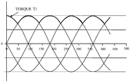
- FIG. 8 illustrates torques acting on the motor disclosed in Japanese Patent No. 06-067259 and Japanese Patent Laid-Open No. 2002-359997 when a constant current is passed through each coil of the motor.
- a current in the positive direction and a current in the reverse direction can be passed through each of two coils, resulting in four different torque curves.
- Each such torque has an almost sinusoidal waveform and a phase difference expressed as an electrical angle of 90 degree.
- Electrical angle as used herein means an angle expressed by using one period of the sinusoidal waveform which is 360 degree.
- the mechanical angle is expressed as electrical angle x 2/n.
- An ideal sequential switching of the energization of a motor during its rotation can, on all occasions, achieve a high torque such as T1 indicated with a bold line of FIG. 8A.
- a switching timing of the energization of the coil is determined by a signal generated from each magnetic sensor.
- the arrangement of two magnetic sensors at an interval of electrical angle of 90 degree permits the switching of energization at the best efficiency.
- Japanese Patent Laid-Open No. 2002-359997 discloses a technology in which a delay time is set that starts from the detection of a rotor rotation position performed by magnetic sensors to accommodate sensor arrangement errors and variations in magnetization angle, thereby performing the switching of energization to each coil.
- a motor driving apparatus as an aspect of the present invention includes a rotor including a magnet, the magnet being cylindrical shaped and divided, in a peripheral direction, into sections each with an outer periphery, each section having a different polarity from adjacent sections, a first yoke including a first magnetic portion, the first yoke being opposed to the outer periphery of the magnet, a first coil configured to, if energized, excite the first magnetic portion, a second yoke including a second magnetic portion, the second yoke being opposed to the outer periphery of the magnet at a position displaced by an electrical angel of approximately 90 degrees relative to the first magnetic portion, a second coil configured to, if energized, excite the second magnetic portion, a detecting portion including a first detection element, a second detection element, a third detection element, and a fourth detection element, each detection element being configured to detect a rotation position of the rotor, and a controller configured to switch a pole excited by the first magnetic portion and the second
- the first detection element is arranged at a position where an advance angle amount from a position at which an electrical advance angle from an excitation switching timing of each first magnetic portion is 0 degree is smaller than a delay angle amount from a position at which an electrical advance angle from an excitation switching timing of each first magnetic portion is 90 degrees if the rotor is caused to rotate in a first rotation direction and if a pole excited by the first magnetic portion is switched based on an output of the first detection element.
- the second detection element is arranged at a position where an advance angle amount from a position at which an electrical advance angle from an excitation switching timing of each second magnetic portion is 0 degree is smaller than a delay angle amount from a position at which an electrical advance angle from an excitation switching timing of each second magnetic portion is 90 degrees if the rotor is caused to rotate in the first rotation direction and if a pole excited by the second magnetic portion is switched based on an output of the second detection element.
- the third detection element is arranged at a position where an advance angle amount from a position at which an electrical advance angle from an excitation switching timing of each first magnetic portion is 0 degree is larger than a delay angle amount from a position at which an electrical advance angle from an excitation switching timing of each first magnetic portion is 90 degrees if the rotor is caused to rotate in the first rotation direction and if a pole excited by the first magnetic portion is switched based on an output of the third detection element.
- the fourth detection element is arranged at a position where an advance angle amount from a position at which an electrical advance angle from an excitation switching timing of each second magnetic portion is 0 degree is larger than a delay angle amount from a position at which an electrical advance angle from an excitation switching timing of each second magnetic portion is 90 degrees if the rotor is caused to rotate in the first rotation direction and if a pole excited by the second magnetic portion is switched based on an output of the fourth detection element.
- the present invention provides a motor driving apparatus which is capable of setting a plurality of advance angles with no delay time and thus causes no loss of synchronization.
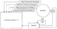
- FIG. 1 is a block diagram of a motor driving apparatus according to an embodiment of the present invention.
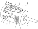
- FIG. 2 is an external perspective view of the motor.
- FIG. 3 is a relationship diagram of a rotor rotation angle and a motor torque.
- FIGS. 4A and 4B are cross-sectional views in a direction at right angles to a motor axis which illustrate the phase relationship between yokes and magnets.
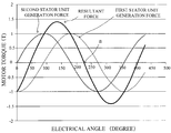
- FIGS. 5A to 5C illustrate torques acting on the rotor when a constant current is passed through the coils of the motor.
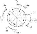
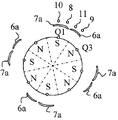
- FIGS. 6A to 6I are cross-sectional views in a direction at right angles to the motor axis which illustrate the phase relationship among the yokes, magnetic sensors, and magnets.
- FIG. 7 is a flow chart of a motor control method.
- FIGS. 8A and 8B illustrate torques acting on the rotor when a constant current is passed through the coils of the motor.
- FIG. 1 is a block diagram of a motor driving apparatus according to an embodiment of the present invention
- FIG. 2 an external perspective view of the motor. It should be noted that some components are illustrated as cutaways for explanation purposes.
- a rotor 3 includes a magnet 2 and is rotatably controlled by a control circuit (a controller) 13.
- the magnet 2 is cylindrical shaped and divided, in a peripheral direction, into sections each with an outer periphery, each section having a different polarity from adjacent sections.
- the magnet 2 is divided into eight sections, i.e., eight magnetized sections, but the pole number may be, for example, four or twelve.
- a first coil 4 is arranged at one end of the magnet 2 in an axis direction.
- the first yoke 6 includes a plurality of first magnetic portions 6a extending from a cylindrical shaped body to the axis direction and arranged in the periphery direction at predetermined intervals. The first magnetic portions 6a are excited by energizing the first coil 4.
- the first coil 4, the first yoke 6, and the magnet 2 opposed to the first magnetic portions 6a together constitute a first stator unit.
- a second coil 5 is arranged at the end opposed to the other end in the axis direction at which the first coil 4 of the magnet 2 is attached.
- the second yoke 7 includes a plurality of second magnetic portions 7a extending from a cylindrical shaped body to the axis direction and arranged in the periphery direction at predetermined intervals. The second magnetic portions 7a are excited by energizing the second coil 5.
- the second coil 5, the second yoke 7, and the magnet 2 opposed to the second magnetic portions 7a together constitute a second stator unit.
- a switching of a pole (N pole/S pole) excited by the first magnetic portions 6a and the second magnetic portions 7a allows a torque given to the rotor 3 to be changed.
- a first magnetic sensor (a first detection element) 8, a second magnetic sensor (a second detection element) 9, a third magnetic sensor (a third detection element) 10, and a fourth magnetic sensor (a fourth detection element) 11 together constitute a detector.
- Each magnetic is a hall element that detects magnetic flux of the magnet 2 and is fixed to a motor cover 12.
- the motor cover 12 fixes and maintains the first yoke 6 and the second yoke 7 such that the first magnetic portions 6a and the second magnetic portions 7a are arranged in an electrical angle of approximately 90 degree relative to the magnetization phase of the magnet 2.
- Electrical angle as used herein means an angle expressed by using one period of the magnetic force of the magnet 2 which is 360 degree.
- the pole number of the rotor 3 is M and the mechanical angle is the electrical angle can be expressed by the following equation.
- an electrical angle of 90 degree is equal to a mechanical angle of 22.5 degree.
- FIG. 3 illustrates the relationship between the rotation angle of the rotor 3 and the torque of the motor 1 when a constant current is passed through the coils of the motor 1.
- the horizontal axis represents an electrical angle
- the vertical axis a motor torque, respectively.
- a torque causing the rotor 3 to be rotated clockwise is defined as positive.
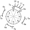
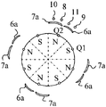
- FIGS. 4A and 4B are cross-sectional views in a direction at right angles to the motor axis which illustrate the phase relationship between each yoke and the magnet 2.
- FIG. 4A illustrates a state in which the distance from the centers of magnetized poles to the first magnetic portions 6a and the distance from the centers of the poles to the second magnetic portions 7a are the same.
- a force maintaining a rotation phase is generated, but a rotation driving force is not generated. This is because the S poles of the magnet 2 are attracted by the first magnetic portions 6a and the second magnetic portions 7a and thus remain in such state.
- the second magnetic portions 7a are excited to be S poles from the state illustrated in FIG 4A, which causes the rotor 3 to rotate to proceed to the state illustrated in FIG. 4B.
- FIG. 4B in the same way as the state illustrated in FIG.4A, a force maintaining a rotation phase is generated, but a rotation driving force is not generated. More specifically, the S poles and the N poles of the magnet 2 are attracted by the first magnetic portions 6a and the second magnetic portions 7a, respectively, and remain in such state.
- the rotor 3 can be caused to continuously rotate by switching the energization directions of the first coil 4 and the second coil 5 to switch the polarities of the first magnetic portions 6a and the second magnetic portions 7a.
- the switching of poles excited by the first magnetic portions 6a and the second magnetic portions 7a in the timing that such rotation driving force is not generated is hereinafter referred to as energization switching with an electrical advance angle of 0 degree.
- the switching of poles excited by the first magnetic portions 6a and the second magnetic portions 7a in the timing earlier than such timing is hereinafter referred to as excitation switching with an electrical advance angle of degree.
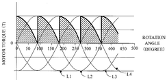
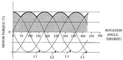
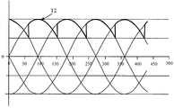
- FIGS. 5A to 5C are diagrams illustrating a rotor rotation angle as a horizontal axis and a motor torque generated when the first coil 4 and the second coil 5 are energized as a vertical axis.
- the horizontal axis is expressed by an electrical angle.
- L1 is a torque curve observed when the energization direction relative to the first coil 4 is positive and the energization direction relative to the second coil 5 is positive.
- L2 is a torque curve observed when the energization direction relative to the first coil 4 is positive and the energization direction relative to the second coil 5 is reverse.
- L3 is a torque curve observed when the energization direction relative to the first coil 4 is reverse and the energization direction relative to the second coil 5 is reverse.
- L4 is a torque curve observed when the energization direction relative to the first coil 4 is reverse and the energization direction relative to the second coil 5 is positive.
- FIG. 5A illustrates a state observed when the electrical advance angel is 0 degree.
- the sequential switching of energization direction relative to each coil in such timing does not yield a large output as an output of the motor 1.
- the reason for this is that the motor torque is, as indicated with oblique-lined portions and a bold line, extremely small in the phase observed immediately prior to the switching of energization direction.
- FIG. 5B illustrates a state observed when the electrical advance angle is 45 degrees. In this state, a motor torque generated when the energization direction is switched is maximized.
- the switching of the energization direction relative to each coil with an electrical advance angle of 90 degrees at an earlier timing yields a motor torque indicated with oblique-lined portions as illustrated in FIG. 5C.
- the resulting torque has a value similar to that obtained when the electrical advance angel is 0 degree. This means that a large rotation driving force cannot be obtained.
- FIGS. 6A to 6I actual operations of the motor 1 will be described, with a default state being the state illustrated in FIG. 6A.
- clockwise rotation operations of the rotor 3 (first energization mode). These operations are done by switching the excitation state of each first magnetic portion 6a by an output signal generated from the first magnetic sensor 8 and by switching the excitation state of each first magnetic portion 7a by an output signal generated from the second magnetic sensor 9.
- the clockwise direction in which the rotor 3 rotates is defined as a first rotation direction.
- Each energization direction is switched in the following combination.
- each first magnetic portion 6a is excited to be an N pole. If the first magnetic sensor 8 detects an N pole of the magnet 2, each first magnetic portion 6a is excited to be an S pole.
- each second magnetic portion 7a is excited to be an S pole. If the second magnetic sensor 9 detects an N pole of the magnet 2, each second magnetic portion 7a is excited to be an N pole.
- each of the first magnetic sensor 8 and the second magnetic sensor 9 detects an S pole of the magnet 2.
- each first magnetic portion 6a is excited to be an N pole and each second magnetic portion 7a an S pole respectively, causing a clockwise rotation force at both the rotor 3 and the magnet 2.
- the first magnetic sensor 8 is arranged such that the excitation switching timing of each first magnetic portion 6a relative to the rotation position of the rotor 3 falls within a range of electrical advance angles of 0 to 45 degrees when a pole excited by each first magnetic portion 6a is switched based on the output of the first magnetic sensor 8.
- This arrangement allows the first magnetic sensor 8 to detect an N pole of the magnet 2 at the time of the transition from the state illustrated in FIG. 6B to the state illustrated in FIG. 6C.
- the first coil 4 is energized such that each first magnetic portion 6a is excited to be an S pole.
- the second magnetic sensor 9 detects an S pole of the magnet 2
- the second coil 5 is energized such that each second magnetic portion 7a is excited to be an S pole, causing a clockwise rotation force at both the rotor 3 and the magnet 2.
- the second magnetic sensor 9 is arranged such that the excitation switching timing of each second magnetic portion 7a relative to the rotation position of the rotor 3 falls within a range of electrical advance angles of 0 to 45 degrees when a pole excited by each second magnetic portion 7a is switched based on the output of the second magnetic sensor 9.
- This arrangement allows the second magnetic sensor 9 to detect an N pole of the magnet 2 at the time of the transition from the state illustrated in FIG. 6D to the state illustrated in FIG. 6E.
- the second coil 5 is energized such that each second magnetic portion 7a is excited to be an N pole.
- the first magnetic sensor 8 detects an N pole of the magnet 2
- the first coil 4 is energized such that each first magnetic portion 6a is excited to be an S pole, causing a clockwise rotation force at both the rotor 3 and the magnet 2.
- the energization is sequentially switched to cause the rotor 3 and the magnet 2 to continuously rotate clockwise.
- the first magnetic sensor 8 is arranged such that the excitation switching timing of each first magnetic portion 6a relative to the rotation position of the rotor 3 falls within a range of electrical advance angles of 0 to 45 degrees when a pole excited by each first magnetic portion 6a is switched based on the output of the first magnetic sensor 8. This means that the first magnetic sensor 8 is arranged at a position where the advance angle amount from the position at which the electrical advance angle from the excitation switching timing of each first magnetic portion 6a is 0 degree is smaller than the delay angle amount from the position at which the electrical advance angle from the excitation switching timing of each first magnetic portion 6a is 90 degrees.
- the second magnetic sensor 9 is arranged such that the excitation switching timing of each second magnetic portion 7a relative to the rotation position of the rotor 3 falls within a range of electrical advance angles of 0 to 45 degrees when a pole excited by each second magnetic portion 7a is switched based on the output of the second magnetic sensor 9. This means that the second magnetic sensor 9 is arranged at a position where the advance angle amount from the position at which the electrical advance angle from the excitation switching timing of each second magnetic portion 7a is 0 degree is smaller than the delay angle amount from the position at which the electrical advance angle from the excitation switching timing of each second magnetic portion 7a is 90 degrees.
- Each energization direction is switched in the following combination.
- each first magnetic portion 6a is excited to be an N pole. If the third magnetic sensor 10 detects an N pole of the magnet 2, each first magnetic portion 6a is excited to be an S pole.
- each second magnetic portion 7a is excited to be an S pole. If the fourth magnetic sensor 11 detects an N pole of the magnet 2, each second magnetic portion 7a is excited to be an N pole.
- each of the third magnetic sensor 10 and the fourth magnetic sensor 11 detects an S pole of the magnet 2.
- each first magnetic portion 6a is excited to be an N pole and each second magnetic portion 7a an S pole respectively, causing a clockwise rotation force at both the rotor 3 and the magnet 2.
- the third magnetic sensor 10 is arranged such that the excitation switching timing of each first magnetic portion 6a relative to the rotation position of the rotor 3 falls within a range of electrical advance angles of 45 to 90 degrees when a pole excited by each first magnetic portion 6a is switched based on the output of the third magnetic sensor 10.
- This arrangement allows the third magnetic sensor 10 to detect an N pole of the magnet 2 at the time of the transition from the state illustrated in FIG. 6A to the state illustrated in FIG. 6B.
- the first coil 4 is energized such that each first magnetic portion 6a is excited to be an S pole.
- the fourth magnetic sensor 11 detects an S pole of the magnet 2
- the second coil 5 is energized such that each second magnetic portion 7a is excited to be an S pole, causing a clockwise rotation force at both the rotor 3 and the magnet 2.
- the fourth magnetic sensor 11 is arranged such that the excitation switching timing of each second magnetic portion 7a relative to the rotation position of the rotor 3 falls within a range of electrical advance angles of 45 to 90 degrees when a pole excited by each second magnetic portion 7a is switched based on the output of the fourth magnetic sensor 11.
- This arrangement allows the fourth magnetic sensor 11 to detect an N pole of the magnet 2 at the time of the transition from the state illustrated in FIG. 6C to the state illustrated in FIG. 6D.
- the second coil 5 is energized such that each second magnetic portion 7a is excited to be an N pole.
- the third magnetic sensor 10 detects an N pole of the magnet 2
- the first coil 4 is energized such that each first magnetic portion 6a is excited to be an S pole, causing a clockwise rotation force at both the rotor 3 and the magnet 2.
- the energization is sequentially switched to cause the rotor 3 and the magnet 2 to continuously rotate clockwise.
- the third magnetic sensor 10 is arranged such that the excitation switching timing of each first magnetic portion 6a relative to the rotation position of the rotor 3 falls within a range of electrical advance angles of 45 to 90 degrees when a pole excited by each first magnetic portion 6a is switched based on the output of the third magnetic sensor 10. This means that the third magnetic sensor 10 is arranged at a position where the advance angle amount from the position at which the electrical advance angle from the excitation switching timing of each first magnetic portion 6a is 0 degree is larger than the delay angle amount from the position at which the electrical advance angle from the excitation switching timing of each first magnetic portion 6a is 90 degrees.
- the fourth magnetic sensor 11 is arranged such that the excitation switching timing of each second magnetic portion 7a relative to the rotation position of the rotor 3 falls within a range of electrical advance angles of 45 to 90 degrees when a pole excited by each second magnetic portion 7a is switched based on the output of the fourth magnetic sensor 11. This means that the fourth magnetic sensor 11 is arranged at a position where the advance angle amount from the position at which the electrical advance angle from the excitation switching timing of each second magnetic portion 7a is 0 degree is larger than the delay angle amount from the position at which the electrical advance angle from the excitation switching timing of each second magnetic portion 7a is 90 degrees.
- This arrangement yields a large rotation driving force because when the rotor 3 rotates at high speed, a timing at which each second magnetic portion 7a is magnetized is a timing at which the electrical advance angle substantially reaches 45 degrees. Consequently, the driving with such an electrical advance angle is desirable especially when the rotor 3 rotates clockwise at high speed.
- Each energization direction is switched in the following combination.
- each first magnetic portion 6a is excited to be an N pole. If the third magnetic sensor 10 detects an N pole of the magnet 2, each first magnetic portion 6a is excited to be an N pole.
- each second magnetic portion 7a is excited to be an N pole. If the second magnetic sensor 9 detects an N pole of the magnet 2, each second magnetic portion 7a is excited to be an S pole.
- each of the third magnetic sensor 10 and the fourth magnetic sensor 11 detects an S pole of the magnet 2.
- each first magnetic portion 6a is excited to be an S pole and each second magnetic portion 7a an N pole respectively, causing a counterclockwise rotation force at both the rotor 3 and the magnet 2.
- the fourth magnetic sensor 11 is arranged such that the excitation switching timing of each second magnetic portion 7a relative to the rotation position of the rotor 3 falls within a range of electrical advance angles of 0 to 45 degrees when a pole excited by each second magnetic portion 7a is switched based on the output of the fourth magnetic sensor 11.
- This arrangement allows the fourth magnetic sensor 11 to detect an N pole of the magnet 2 at the time of the transition from the state illustrated in FIG. 6F to the state illustrated in FIG. 6G.
- the second coil 5 is energized such that each second magnetic portion 7a is excited to be an S pole.
- the third magnetic sensor 10 detects an S pole of the magnet 2
- the first coil 4 is energized such that each first magnetic portion 6a is excited to be an S pole, causing a counterclockwise rotation force at both the rotor 3 and the magnet 2.
- the third magnetic sensor 10 is arranged such that the excitation switching timing of each first magnetic portion 6a relative to the rotation position of the rotor 3 falls within a range of electrical advance angles of 0 to 45 degrees when a pole excited by each first magnetic portion 6a is switched based on the output of the third magnetic sensor 10.
- This arrangement allows the third magnetic sensor 9 to detect an N pole of the magnet 2 at the time of the transition from the state illustrated in FIG. 6H to the state illustrated in FIG. 6I.
- the first coil 4 is energized such that each first magnetic portion 6a is excited to be an N pole.
- the fourth magnetic sensor 11 detects an N pole of the magnet 2
- the second coil 5 is energized such that each second magnetic portion 7a is excited to be an S pole, causing a counterclockwise rotation force at both the rotor 3 and the magnet 2.
- the energization is sequentially switched to cause the rotor 3 and the magnet 2 to continuously rotate counterclockwise.
- the third magnetic sensor 10 is arranged such that the excitation switching timing of each first magnetic portion 6a relative to the rotation position of the rotor 3 falls within a range of electrical advance angles of 0 to 45 degrees when a pole excited by each first magnetic portion 6a is switched based on the output of the third magnetic sensor 10.
- the fourth magnetic sensor 11 is arranged such that the excitation switching timing of each second magnetic portion 7a relative to the rotation position of the rotor 3 falls within a range of electrical advance angles of 0 to 45 degrees when a pole excited by each second magnetic portion 7a is switched based on the output of the fourth magnetic sensor 11.
- Each energization direction is switched in the following combination.
- each first magnetic portion 6a is excited to be an S pole. If the first magnetic sensor 8 detects an N pole of the magnet 2, each first magnetic portion 6a is excited to be an N pole.
- each second magnetic portion 7a is excited to be an N pole. If the second magnetic sensor 9 detects an N pole of the magnet 2, each second magnetic portion 7a is excited to be an S pole.
- each of the first magnetic sensor 8 and the second magnetic sensor 9 detects an S pole of the magnet 2.
- each first magnetic portion 6a is excited to be an S pole and each second magnetic portion 7a an N pole respectively, causing a counterclockwise rotation force at both the rotor 3 and the magnet 2.
- the second magnetic sensor 9 is arranged such that the excitation switching timing of each second magnetic portion 7a relative to the rotation position of the rotor 3 falls within a range of electrical advance angles of 45 to 90 degrees when a pole excited by each second magnetic portion 7a is switched based on the output of the second magnetic sensor 9.
- This arrangement allows the second magnetic sensor 9 to detect an N pole of the magnet 2 at the time of the transition from the state illustrated in FIG. 6A to the state illustrated in FIG. 6F.
- the second coil 5 is energized such that each second magnetic portion 7a is excited to be an S pole.
- the first magnetic sensor 8 detects an S pole of the magnet 2
- the first coil 4 is energized such that each first magnetic portion 6a is excited to be an S pole, causing a counterclockwise rotation force at both the rotor 3 and the magnet 2.
- the first magnetic sensor 8 is arranged such that the excitation switching timing of each first magnetic portion 6a relative to the rotation position of the rotor 3 falls within a range of electrical advance angles of 45 to 90 degrees when a pole excited by each first magnetic portion 6a is switched based on the output of the first magnetic sensor 8.
- This arrangement allows the first magnetic sensor 8 to detect an N pole of the magnet 2 at the time of the transition from the state illustrated in FIG. 6G to the state illustrated in FIG. 6H.
- the first coil 4 is energized such that each first magnetic portion 6a is excited to be an N pole.
- the second magnetic sensor 9 detects an N pole of the magnet 2
- the second coil 5 is energized such that each second magnetic portion 7a is excited to be an S pole, causing a counterclockwise rotation force at both the rotor 3 and the magnet 2.
- the energization is sequentially switched to cause the rotor 3 and the magnet 2 to continuously rotate counterclockwise.
- the first magnetic sensor 8 is arranged such that the excitation switching timing of each first magnetic portion 6a relative to the rotation position of the rotor 3 falls within a range of electrical advance angles of 45 to 90 degrees when a pole excited by each first magnetic portion 6a is switched based on the output of the first magnetic sensor 8.
- the second magnetic sensor 9 is arranged such that the excitation switching timing of each second magnetic portion 7a relative to the rotation position of the rotor 3 falls within a range of electrical advance angles of 45 to 90 degrees when a pole excited by each second magnetic portion 7a is switched based on the output of the second magnetic sensor 9.
- each sensor is arranged as follows.
- the first magnetic sensor 8 is arranged such that the excitation switching timing of each first magnetic portion 6a relative to the rotation position of the rotor 3 falls within a range of electrical advance angles of 0 to 45 degrees when a pole excited by each first magnetic portion 6a is switched based on the output of the first magnetic sensor 8.
- the second magnetic sensor 9 is arranged such that the excitation switching timing of each second magnetic portion 7a relative to the rotation position of the rotor 3 falls within a range of electrical advance angles of 0 to 45 degrees when a pole excited by each second magnetic portion 7a is switched based on the output of the second magnetic sensor 9.
- the third magnetic sensor 10 is arranged such that the excitation switching timing of each first magnetic portion 6a relative to the rotation position of the rotor 3 falls within a range of electrical advance angles of 45 to 90 degrees when a pole excited by each first magnetic portion 6a is switched based on the output of the third magnetic sensor 10.
- the fourth magnetic sensor 11 is arranged such that the excitation switching timing of each second magnetic portion 7a relative to the rotation position of the rotor 3 falls within a range of electrical advance angles of 45 to 90 degrees when a pole excited by each second magnetic portion 7a is switched based on the output of the fourth magnetic sensor 11.
- each magnetic sensor is arranged as follows.
- the first magnetic sensor 8 is arranged such that the excitation switching timing of each first magnetic portion 6a relative to the rotation position of the rotor 3 falls within a range of electrical advance angles of 45 to 90 degrees when a pole excited by each first magnetic portion 6a is switched based on the output of the first magnetic sensor 8.
- the second magnetic sensor 9 is arranged such that the excitation switching timing of each second magnetic portion 7a relative to the rotation position of the rotor 3 falls within a range of electrical advance angles of 45 to 90 degrees when a pole excited by each second magnetic portion 7a is switched based on the output of the second magnetic sensor 9.
- the third magnetic sensor 10 is arranged such that the excitation switching timing of each first magnetic portion 6a relative to the rotation position of the rotor 3 falls within a range of electrical advance angles of 0 to 45 degrees when a pole excited by each first magnetic portion 6a is switched based on the output of the third magnetic sensor 10.
- the fourth magnetic sensor 11 is arranged such that the excitation switching timing of each second magnetic portion 7a relative to the rotation position of the rotor 3 falls within a range of electrical advance angles of 0 to 45 degrees when a pole excited by each second magnetic portion 7a is switched based on the output of the fourth magnetic sensor 11.
- each magnet sensor needs to be arranged at an appropriate position where a large rotation driving force can be obtained, taking into consideration factors such as magnetization errors of the magnet 2, sensor size errors, and yoke errors.
- each magnetic sensor is preferably arranged as follows.
- the first magnetic sensor 8 is preferably arranged such that the excitation switching timing of the first stator unit falls within a range of electrical advance angle of 14.4 to 33.6 degrees.
- the third magnetic sensor 10 is preferably arranged such that the excitation switching timing of each fist magnetic portion 6a falls within a range of electrical advance angle of 56.4 to 75.6 degrees.
- the second magnetic sensor 9 is preferably arranged such that the excitation switching timing of each second magnetic portion 7a falls within a range of electrical advance angle of 14.4 to 33.6 degrees.
- the fourth magnetic sensor 11 is preferably arranged such that the excitation switching timing of each second magnetic portion 7a falls within a range of electrical advance angle of 56.4 to 75.6 degrees.
- each magnetic sensor is preferably arranged as follows.
- the first magnetic sensor 8 is preferably arranged such that the excitation switching timing of each first magnetic portion 6a falls within a range of electrical advance angle of 56.4 to 75.6 degrees.
- the third magnetic sensor 10 is preferably arranged such that the excitation switching timing of each first magnetic portion 6a falls within a range of electrical advance angle of 14.4 to 33.6 degrees.
- the second magnetic sensor 9 is preferably arranged such that the excitation switching timing of each second magnetic portion 7a falls within a range of electrical advance angle of 56.4 to 75.6 degrees.
- the fourth magnetic sensor 11 is preferably arranged such that the excitation switching timing of each second magnetic portion 7a falls within a range of electrical advance angle of 14.4 to 33.6 degrees.
- each magnetic sensor needs to be arranged such that the middle point of a line connecting the first magnetic sensor 8 and the third magnetic sensor 10 is located at a position where the excitation switching timing of each first magnetic portion 6a reaches an electrical advance angle of 45 degrees.
- each magnetic sensor needs to be arranged such that the middle point of a line connecting the second magnetic sensor 9 and the fourth magnetic sensor 11 is located at a position where the excitation switching timing of each second magnetic portion 7a reaches an electrical advance angle of 45 degrees.
- the first magnetic sensor 8 is arranged at a position where the excitation switching timing of each first magnetic portion 6a reaches an electrical advance angle of 21 degrees and the third magnetic sensor 10 at a position where the excitation switching timing of each first magnetic portion 6a reaches an electrical advance angle of 69 degrees, respectively.
- the second magnetic sensor 9 is arranged at a position where the excitation switching timing of each second magnetic portion 7a reaches an electrical advance angle of 21 degrees and the fourth magnetic sensor 11 at a position where the excitation switching timing of each second magnetic portion 7a reaches an electrical advance angle of 69 degrees, respectively.
- step S1 the rotation direction of the rotor 3 is selected.
- the process proceeds to step S2 if the rotation direction is clockwise or step S102 if the rotation direction is counterclockwise.
- step S2 an energization in the first energization mode is performed. More specifically, the excitation of each first magnetic portion 6a and each second magnetic portion 7a is switched based on the output of the first magnetic sensor 8 and the second magnetic sensor 9 respectively to cause the rotor 3 and magnet 2 to rotate clockwise.
- step S3 the rotation speed of the rotor 3 is determined.
- the rotation speed of the rotor 3 may be measured by using each magnetic sensor or by using known speed detectors (not illustrated in the figure). If the rotation speed is less than a predetermined speed, the process proceeds to step S4, or if the rotation speed is equal to or more than such predetermined speed, the process proceeds to step S5.
- step S4 the driving rotation amount of the rotor 3 is determined. If the total rotation amount reaches the driving rotation amount A less a predetermined amount B, the process proceeds to step S7.
- step S5 an energization in the second energization mode is performed. More specifically, the excitation of each first magnetic portion 6a and each second magnetic portion 7a is switched based on the output of the third magnetic sensor 10 and the fourth magnetic sensor 11 respectively to cause the rotor 3 and magnet 2 to rotate clockwise.
- step S6 the driving rotation amount of the rotor 3 is determined. If the total rotation amount reaches the driving rotation amount A less a predetermined amount B, the process proceeds to step S7.
- step S7 an energization in the second energization mode is performed. More specifically, the excitation of each first magnetic portion 6a and each second magnetic portion 7a is switched based on the output of the third magnetic sensor 10 and the fourth magnetic sensor 11 respectively to cause the rotor 3 and magnet 2 to rotate counterclockwise. During this counterclockwise rotation, the rotor 3 and the magnet 2 are rapidly slowed down due to a clockwise-direction driving force given to them, but with their counterclockwise rotation being continued by virtue of their inertial mass.
- An energization in the fourth energization mode may be alternatively performed in step S7.
- step S8 the rotation speed of the rotor 3 is determined.
- the process proceeds to step S9.
- step S9 the driving mode is switched from brushless driving in which the energization direction is switched by the feedback of an output generated from each magnetic sensor to stepping driving with an pulse signal, which is a driving method for normal PM2-type two-phase stepping motors.
- step S10 if the total rotation amount reaches the driving rotation amount A, the process proceeds to step S11.
- step S11 the stepping driving is stopped to stop the rotor 3 at a target position.
- step S102 an energization in the third energization mode is performed. More specifically, the excitation of each first magnetic portion 6a and each second magnetic portion 7a is switched based on the output of the third magnetic sensor 10 and the fourth magnetic sensor 11 respectively to cause the rotor 3 and magnet 2 to rotate counterclockwise.
- step S103 the rotation speed of the rotor 3 is determined. More specifically, the rotation speed of the rotor 3 may be measured by using each magnetic sensor or by using known speed detectors (not illustrated in the figure). If the rotation speed is less than a predetermined speed, the process proceeds to step S104, or if the rotation speed is equal to or more than such predetermined speed, the process proceeds to step S105.
- step S104 the driving rotation amount of the rotor 3 is determined. If the total rotation amount reaches the driving rotation amount A less a predetermined amount B, the process proceeds to step S107.
- step S105 an energization in the fourth energization mode is performed. More specifically, the excitation of each first magnetic portion 6a and each second magnetic portion 7a is switched based on the output of the first magnetic sensor 8 and the second magnetic sensor 9 respectively to cause the rotor 3 and magnet 2 to rotate counterclockwise.
- step S106 the driving rotation amount of the rotor 3 is determined. If the total rotation amount reaches the driving rotation amount A less a predetermined amount B, the process proceeds to step S107.
- step S107 an energization in the first energization mode is performed. More specifically, the excitation of each first magnetic portion 6a and each second magnetic portion 7a is switched based on the output of the first magnetic sensor 8 and the second magnetic sensor 9 respectively to cause the rotor 3 and magnet 2 to rotate clockwise. During this clockwise rotation, the rotor 3 and the magnet 2 are rapidly slowed down due to a counterclockwise-direction driving force given to them, but with their clockwise rotation being continued by virtue of their inertial mass.
- An energization in the second energization mode may be alternatively performed in step S107.
- step S108 the rotation speed of the rotor 3 is determined.
- the process proceeds to step S109.
- step S109 the driving mode is switched from brushless driving in which the energization direction is switched by the feedback of an output generated from each magnetic sensor to stepping driving with an pulse signal, which is a driving method for normal PM2-type two-phase stepping motors.
- step S110 if the total rotation amount reaches the driving rotation amount A, the process proceeds to step S111.
- step S111 the stepping driving is stopped to stop the rotor 3 at a target position.
- a plurality of advance angles can be set with no delay time. This setting permits driving control with two different advance angles in both clockwise and counterclockwise rotation directions.
- an energization at the time of transition from driving sate to stop state, in a phase with an energization advance angle observed during the reverse rotation allows a rapid slow down, which in turn leads to a higher stop control ability.
- the present invention provides a motor driving apparatus which is capable of setting a plurality of advance angles with no delay time and thus causes no loss of synchronization.
Abstract
Description

2 MAGNET
3 ROTOR
4 FIRST COIL
5 SECOND COIL
6 FIRST YOKE
6a FIRST MAGNETIC PORTION
7 SECOND YOKE
7a SECOND MAGNETIC PORTION
8 FIRST MAGNETIC SENSOR
9 SECOND MAGNETIC SENSOR
10 THIRD MAGNETIC SENSOR
11 FOURTH MAGNETIC SENSOR
12 MOTOR COVER
13 CONTROL CIRCUIT
Claims (6)
- A motor driving apparatus comprising:
a rotor including a magnet, the magnet being cylindrical shaped and divided, in a peripheral direction, into sections each with an outer periphery, each section having a different polarity from adjacent sections;
a first yoke including a first magnetic portion, the first yoke being opposed to the outer periphery of the magnet;
a first coil configured to, if energized, excite the first magnetic portion;
a second yoke including a second magnetic portion, the second yoke being opposed to the outer periphery of the magnet at a position displaced by an electrical angel of 90 degrees relative to the first magnetic portion;
a second coil configured to, if energized, excite the second magnetic portion;
a detecting portion including a first detection element, a second detection element, a third detection element, and a fourth detection element, each detection element being configured to detect a rotation position of the rotor; and
a controller configured to switch a pole excited by the first magnetic portion and the second magnetic portion by switching an energization direction of the first coil and the second coil based on an output of the detecting portion,
wherein the first detection element is arranged at a position where an advance angle amount from a position at which an electrical advance angle from an excitation switching timing of each first magnetic portion is 0 degree is smaller than a delay angle amount from a position at which an electrical advance angle from an excitation switching timing of each first magnetic portion is 90 degrees if the rotor is caused to rotate in a first rotation direction and if a pole excited by the first magnetic portion is switched based on an output of the first detection element,
wherein the second detection element is arranged at a position where an advance angle amount from a position at which an electrical advance angle from an excitation switching timing of each second magnetic portion is 0 degree is smaller than a delay angle amount from a position at which an electrical advance angle from an excitation switching timing of each second magnetic portion is 90 degrees if the rotor is caused to rotate in the first rotation direction and if a pole excited by the second magnetic portion is switched based on an output of the second detection element,
wherein the third detection element is arranged at a position where an advance angle amount from a position at which an electrical advance angle from an excitation switching timing of each first magnetic portion is 0 degree is larger than a delay angle amount from a position at which an electrical advance angle from an excitation switching timing of each first magnetic portion is 90 degrees if the rotor is caused to rotate in the first rotation direction and if a pole excited by the first magnetic portion is switched based on an output of the third detection element, and
wherein the fourth detection element is arranged at a position where an advance angle amount from a position at which an electrical advance angle from an excitation switching timing of each second magnetic portion is 0 degree is larger than a delay angle amount from a position at which an electrical advance angle from an excitation switching timing of each second magnetic portion is 90 degrees if the rotor is caused to rotate in the first rotation direction and if a pole excited by the second magnetic portion is switched based on an output of the fourth detection element.
- The motor driving apparatus according to claim 1,
wherein the first detection element is arranged at a position where an excitation switching timing of each first magnetic portion relative to a rotation position of the rotor falls within a range of electrical advance angles of 0 to 45 degrees if the rotor is caused to rotate in the first rotation direction and if a pole excited by the first magnetic portion is switched based on an output of the first detection element,
wherein the second detection element is arranged at a position where an excitation switching timing of each second magnetic portion relative to a rotation position of the rotor falls within a range of electrical advance angles of 0 to 45 degrees if the rotor is caused to rotate in the first rotation direction and if a pole excited by the second magnetic portion is switched based on an output of the second detection element,
wherein the third detection element is arranged at a position where an excitation switching timing of each first magnetic portion relative to a rotation position of the rotor falls within a range of electrical advance angles of 45 to 90 degrees if the rotor is caused to rotate in the first rotation direction and if a pole excited by the first magnetic portion is switched based on an output of the third detection element, and
wherein the fourth detection element is arranged at a position where an excitation switching timing of each second magnetic portion relative to a rotation position of the rotor falls within a range of electrical advance angles of 45 to 90 degrees if the rotor is caused to rotate in the first rotation direction and if a pole excited by the second magnetic portion is switched based on an output of the fourth detection element.
- The motor driving apparatus according to claim 2,
wherein the first detection element is arranged at a position where an excitation switching timing of each first magnetic portion relative to a rotation position of the rotor falls within a range of electrical advance angles of 45 to 90 degrees if the rotor is caused to rotate in a second rotation direction, which is a reverse direction to the first rotation direction, and if a pole excited by the first magnetic portion is switched based on an output of the first detection element,
wherein the second detection element is arranged at a position where an excitation switching timing of each second magnetic portion relative to a rotation position of the rotor falls within a range of electrical advance angles of 45 to 90 degrees if the rotor is caused to rotate in the second rotation direction and if a pole excited by the second magnetic portion is switched based on an output of the second detection element,
wherein the third detection element is arranged at a position where an excitation switching timing of each first magnetic portion relative to a rotation position of the rotor falls within a range of electrical advance angles of 0 to 45 degrees if the rotor is caused to rotate in the second rotation direction and if a pole excited by the first magnetic portion is switched based on an output of the third detection element, and
wherein the fourth detection element is arranged at a position where an excitation switching timing of each second magnetic portion relative to a rotation position of the rotor falls within a range of electrical advance angles of 0 to 45 degrees if the rotor is caused to rotate in the second rotation direction and if a pole excited by the second magnetic portion is switched based on an output of the fourth detection element.
- The motor driving apparatus according to claim 1, further comprising:
a speed detecting portion,
wherein the controller switches an energization direction of the first coil based on an output of the first detection element and an energization direction of the second coil based on an output of the second detection element if the rotor is caused to rotate in the first rotation direction and if a rotation speed of the rotor detected by the speed detecting portion is less than a predetermined rotation speed,
wherein the controller switches an energization direction of the first coil based on an output of the third detection element and an energization direction of the second coil based on an output of the fourth detection element if the rotor is caused to rotate in the first rotation direction and if a rotation speed of the rotor detected by the speed detecting portion is equal to or more than the predetermined rotation speed,
wherein the controller switches an energization direction of the first coil based on an output of the third detection element and an energization direction of the second coil based on an output of the fourth detection element if the rotor is caused to rotate in the second rotation direction and if a rotation speed of the rotor detected by the speed detecting portion is less than the predetermined rotation speed,
wherein the controller switches an energization direction of the first coil based on an output of the first detection element and an energization direction of the second coil based on an output of the second detection element if the rotor is caused to rotate in the second rotation direction and if a rotation speed of the rotor detected by the speed detecting portion is equal to or more than the predetermined rotation speed.
- The motor driving apparatus according to claim 2,
wherein the first detection element is arranged at an position where an excitation timing of the first magnetic portion relative to a rotation position of the rotor falls within a range of electrical advance angle of 14.4 to 33.6 degrees if the rotor is caused to rotate in the first rotation direction and if a pole excited by the first magnetic portion is switched based on an output of the first detection element,
wherein the second detection element is arranged at an position where an excitation timing of the second magnetic portion relative to a rotation position of the rotor falls within a range of electrical advance angle of 14.4 to 33.6 degrees if the rotor is caused to rotate in the first rotation direction and if a pole excited by the second magnetic portion is switched based on an output of the second detection element,
wherein the third detection element is arranged at an position where an excitation timing of the first magnetic portion relative to a rotation position of the rotor falls within a range of electrical advance angle of 56.4 to 75.6 degrees if the rotor is caused to rotate in the first rotation direction and if a pole excited by the first magnetic portion is switched based on an output of the third detection element, and
wherein the fourth detection element is arranged at an position where an excitation timing of the second magnetic portion relative to a rotation position of the rotor falls within a range of electrical advance angle of 56.4 to 75.6 degrees if the rotor is caused to rotate in the first rotation direction and if a pole excited by the second magnetic portion is switched based on an output of the fourth detection element.
- The motor driving apparatus according to claim 3,
wherein the first detection element is arranged at an position where an excitation timing of the first magnetic portion relative to a rotation position of the rotor falls within a range of electrical advance angle of 56.4 to 75.6 degrees if the rotor is caused to rotate in the second rotation direction and if a pole excited by the first magnetic portion is switched based on an output of the first detection element,
wherein the second detection element is arranged at an position where an excitation timing of the second magnetic portion relative to a rotation position of the rotor falls within a range of electrical advance angle of 56.4 to 75.6 degrees if the rotor is caused to rotate in the second rotation direction and if a pole excited by the second magnetic portion is switched based on an output of the second detection element,
wherein the third detection element is arranged at an position where an excitation timing of the first magnetic portion relative to a rotation position of the rotor falls within a range of electrical advance angle of 14.4 to 33.6 degrees if the rotor is caused to rotate in the second rotation direction and if a pole excited by the first magnetic portion is switched based on an output of the third detection element, and
wherein the fourth detection element is arranged at an position where an excitation timing of the second magnetic portion relative to a rotation position of the rotor falls within a range of electrical advance angle of 14.4 to 33.6 degrees if the rotor is caused to rotate in the second rotation direction and if a pole excited by the second magnetic portion is switched based on an output of the fourth detection element.
Priority Applications (5)
| Application Number | Priority Date | Filing Date | Title |
|---|---|---|---|
| KR1020157016423A KR101739670B1 (en) | 2012-12-27 | 2013-12-19 | A motor driving apparatus |
| CN201380068491.7A CN104885348B (en) | 2012-12-27 | 2013-12-19 | Motor driving apparatus |
| US14/652,429 US9553535B2 (en) | 2012-12-27 | 2013-12-19 | Motor driving apparatus |
| EP13867328.0A EP2939335B1 (en) | 2012-12-27 | 2013-12-19 | A motor driving apparatus |
| RU2015119027A RU2609606C2 (en) | 2012-12-27 | 2013-12-19 | Motor actuating device |
Applications Claiming Priority (2)
| Application Number | Priority Date | Filing Date | Title |
|---|---|---|---|
| JP2012284086A JP6120563B2 (en) | 2012-12-27 | 2012-12-27 | Motor drive device |
| JP2012-284086 | 2012-12-27 |
Publications (1)
| Publication Number | Publication Date |
|---|---|
| WO2014103258A1 true WO2014103258A1 (en) | 2014-07-03 |
Family
ID=51020378
Family Applications (1)
| Application Number | Title | Priority Date | Filing Date |
|---|---|---|---|
| PCT/JP2013/007468 WO2014103258A1 (en) | 2012-12-27 | 2013-12-19 | A motor driving apparatus |
Country Status (8)
| Country | Link |
|---|---|
| US (1) | US9553535B2 (en) |
| EP (1) | EP2939335B1 (en) |
| JP (1) | JP6120563B2 (en) |
| KR (1) | KR101739670B1 (en) |
| CN (1) | CN104885348B (en) |
| MY (1) | MY187913A (en) |
| RU (1) | RU2609606C2 (en) |
| WO (1) | WO2014103258A1 (en) |
Cited By (1)
| Publication number | Priority date | Publication date | Assignee | Title |
|---|---|---|---|---|
| US20170212496A1 (en) * | 2016-01-21 | 2017-07-27 | Canon Kabushiki Kaisha | Motor driving apparatus |
Families Citing this family (9)
| Publication number | Priority date | Publication date | Assignee | Title |
|---|---|---|---|---|
| US10135369B2 (en) * | 2015-09-29 | 2018-11-20 | Microchip Technology Incorporated | Linear hall effect sensors for multi-phase permanent magnet motors with PWM drive |
| KR102146023B1 (en) * | 2016-01-07 | 2020-08-19 | 엘지이노텍 주식회사 | Motor and electronic power steering system having the same |
| US10547256B2 (en) | 2017-11-08 | 2020-01-28 | Canon Kabushiki Kaisha | Motor driving apparatus capable of reliably starting motor, and method of controlling same |
| JP2019122170A (en) * | 2018-01-09 | 2019-07-22 | キヤノン株式会社 | Motor control device and method |
| US10756657B2 (en) | 2018-01-12 | 2020-08-25 | Canon Kabushiki Kaisha | Motor control apparatus and motor control method for reducing influence of magnetic fluxes from yokes |
| JP2019126244A (en) * | 2018-01-12 | 2019-07-25 | キヤノン株式会社 | Motor controller and control method |
| JP2020048335A (en) | 2018-09-19 | 2020-03-26 | キヤノン株式会社 | Actuator control device, its control method, and control program |
| CN109450134B (en) * | 2018-11-15 | 2020-12-18 | 白贺冰 | Single-phase multi-pole motor for vehicle |
| CN112666624B (en) * | 2020-12-29 | 2022-06-07 | 杭州微伽量子科技有限公司 | Quantum absolute gravimeter |
Citations (3)
| Publication number | Priority date | Publication date | Assignee | Title |
|---|---|---|---|---|
| JPH0223092A (en) * | 1988-07-12 | 1990-01-25 | Secoh Giken Inc | Motor operated by output torque designated by ac power source |
| JP2006105652A (en) * | 2004-10-01 | 2006-04-20 | Japan Atom Energy Res Inst | High precision position detection control method by radiation-resistant rotation detector using proximity sensor, and device used for the method |
| JP2012068921A (en) * | 2010-09-24 | 2012-04-05 | Ckd Corp | Electric actuator |
Family Cites Families (12)
| Publication number | Priority date | Publication date | Assignee | Title |
|---|---|---|---|---|
| JPH0667259A (en) | 1992-08-24 | 1994-03-11 | Canon Inc | Optical equipment |
| RU2118039C1 (en) | 1995-04-14 | 1998-08-20 | Научно-производственное предприятие "Эметрон" | Inductor motor control method |
| JP2002023092A (en) * | 2000-07-03 | 2002-01-23 | Sharp Corp | Optical scanning device |
| FR2820252B1 (en) | 2001-01-31 | 2004-07-09 | Midi Ingenierie | BRUSHLESS MOTOR CONTROL SYSTEM |
| JP2002359997A (en) | 2001-03-26 | 2002-12-13 | Fdk Corp | Stepper motor and driving control method therefor |
| JP4796779B2 (en) * | 2005-03-29 | 2011-10-19 | 日本電産コパル株式会社 | Stepping motor and fan including the same |
| JP5241184B2 (en) | 2007-09-14 | 2013-07-17 | キヤノン株式会社 | motor |
| JP5656354B2 (en) | 2008-10-20 | 2015-01-21 | キヤノン株式会社 | Drive device |
| JP5515426B2 (en) * | 2009-05-28 | 2014-06-11 | 日本電産株式会社 | motor |
| JP5441624B2 (en) * | 2009-11-05 | 2014-03-12 | キヤノン株式会社 | Motor drive device |
| JP5574837B2 (en) | 2010-06-16 | 2014-08-20 | キヤノン株式会社 | Imaging device |
| JP6184134B2 (en) | 2013-03-12 | 2017-08-23 | キヤノン株式会社 | Motor drive device and control method thereof |
-
2012
- 2012-12-27 JP JP2012284086A patent/JP6120563B2/en not_active Expired - Fee Related
-
2013
- 2013-12-19 EP EP13867328.0A patent/EP2939335B1/en not_active Not-in-force
- 2013-12-19 CN CN201380068491.7A patent/CN104885348B/en not_active Expired - Fee Related
- 2013-12-19 RU RU2015119027A patent/RU2609606C2/en active
- 2013-12-19 MY MYPI2015701231A patent/MY187913A/en unknown
- 2013-12-19 WO PCT/JP2013/007468 patent/WO2014103258A1/en active Application Filing
- 2013-12-19 US US14/652,429 patent/US9553535B2/en active Active
- 2013-12-19 KR KR1020157016423A patent/KR101739670B1/en active IP Right Grant
Patent Citations (3)
| Publication number | Priority date | Publication date | Assignee | Title |
|---|---|---|---|---|
| JPH0223092A (en) * | 1988-07-12 | 1990-01-25 | Secoh Giken Inc | Motor operated by output torque designated by ac power source |
| JP2006105652A (en) * | 2004-10-01 | 2006-04-20 | Japan Atom Energy Res Inst | High precision position detection control method by radiation-resistant rotation detector using proximity sensor, and device used for the method |
| JP2012068921A (en) * | 2010-09-24 | 2012-04-05 | Ckd Corp | Electric actuator |
Cited By (2)
| Publication number | Priority date | Publication date | Assignee | Title |
|---|---|---|---|---|
| US20170212496A1 (en) * | 2016-01-21 | 2017-07-27 | Canon Kabushiki Kaisha | Motor driving apparatus |
| US10591893B2 (en) * | 2016-01-21 | 2020-03-17 | Canon Kabushiki Kaisha | Motor driving apparatus |
Also Published As
| Publication number | Publication date |
|---|---|
| EP2939335A1 (en) | 2015-11-04 |
| CN104885348B (en) | 2017-09-05 |
| RU2015119027A (en) | 2017-01-30 |
| US20150326157A1 (en) | 2015-11-12 |
| CN104885348A (en) | 2015-09-02 |
| JP2014128143A (en) | 2014-07-07 |
| MY187913A (en) | 2021-10-28 |
| EP2939335A4 (en) | 2016-11-02 |
| KR20150086539A (en) | 2015-07-28 |
| RU2609606C2 (en) | 2017-02-02 |
| EP2939335B1 (en) | 2019-10-02 |
| US9553535B2 (en) | 2017-01-24 |
| JP6120563B2 (en) | 2017-04-26 |
| KR101739670B1 (en) | 2017-05-24 |
Similar Documents
| Publication | Publication Date | Title |
|---|---|---|
| EP2939335B1 (en) | A motor driving apparatus | |
| JP5469730B2 (en) | How to start a brushless motor | |
| JP2009189091A (en) | Linear actuator | |
| JP2010112978A (en) | Lens drive device, lens position detecting device, and imaging apparatus using them | |
| JP2019037035A (en) | Motor driving device, control method therefor, and control program therefor | |
| US10756657B2 (en) | Motor control apparatus and motor control method for reducing influence of magnetic fluxes from yokes | |
| JP2005122026A (en) | Lens barrel and imaging apparatus | |
| JP2019071028A (en) | Motor control apparatus, motor control method, and imaging apparatus | |
| JP5511445B2 (en) | Motor and motor drive control method | |
| JP5828678B2 (en) | Motor control device and motor drive device | |
| JP2011120342A (en) | Motor driver | |
| JP5885419B2 (en) | Motor driving device and control method of motor driving device | |
| JP5159287B2 (en) | Image shake correction apparatus, imaging apparatus, and image shake correction apparatus control method | |
| JPH0974779A (en) | Drive control apparatus | |
| JP5489738B2 (en) | Motor control device and optical apparatus | |
| KR100445661B1 (en) | Single Phase Motor | |
| JP2020099169A (en) | Motor drive device and control method of the same | |
| US10547256B2 (en) | Motor driving apparatus capable of reliably starting motor, and method of controlling same | |
| JP2019103335A (en) | Motor driving device, mirror driving device, and imaging apparatus | |
| JP2019122170A (en) | Motor control device and method | |
| JP2021023000A (en) | motor | |
| JP2020036492A (en) | motor | |
| JP2020096489A (en) | Motor unit and driving method of the same | |
| JP2020096488A (en) | Motor unit and driving method of the same | |
| JPH088765B2 (en) | Motor drive |
Legal Events
| Date | Code | Title | Description |
|---|---|---|---|
| 121 | Ep: the epo has been informed by wipo that ep was designated in this application |
Ref document number: 13867328 Country of ref document: EP Kind code of ref document: A1 |
|
| DPE1 | Request for preliminary examination filed after expiration of 19th month from priority date (pct application filed from 20040101) | ||
| WWE | Wipo information: entry into national phase |
Ref document number: 2013867328 Country of ref document: EP |
|
| WWE | Wipo information: entry into national phase |
Ref document number: 14652429 Country of ref document: US |
|
| ENP | Entry into the national phase |
Ref document number: 20157016423 Country of ref document: KR Kind code of ref document: A |
|
| NENP | Non-entry into the national phase |
Ref country code: DE |
|
| ENP | Entry into the national phase |
Ref document number: 2015119027 Country of ref document: RU Kind code of ref document: A |