RU2609606C2 - Motor actuating device - Google Patents
Motor actuating device Download PDFInfo
- Publication number
- RU2609606C2 RU2609606C2 RU2015119027A RU2015119027A RU2609606C2 RU 2609606 C2 RU2609606 C2 RU 2609606C2 RU 2015119027 A RU2015119027 A RU 2015119027A RU 2015119027 A RU2015119027 A RU 2015119027A RU 2609606 C2 RU2609606 C2 RU 2609606C2
- Authority
- RU
- Russia
- Prior art keywords
- magnetic part
- rotor
- rotation
- detecting element
- degrees
- Prior art date
Links
Images


Classifications
-
- H—ELECTRICITY
- H02—GENERATION; CONVERSION OR DISTRIBUTION OF ELECTRIC POWER
- H02P—CONTROL OR REGULATION OF ELECTRIC MOTORS, ELECTRIC GENERATORS OR DYNAMO-ELECTRIC CONVERTERS; CONTROLLING TRANSFORMERS, REACTORS OR CHOKE COILS
- H02P8/00—Arrangements for controlling dynamo-electric motors of the kind having motors rotating step by step
- H02P8/14—Arrangements for controlling speed or speed and torque
-
- H—ELECTRICITY
- H02—GENERATION; CONVERSION OR DISTRIBUTION OF ELECTRIC POWER
- H02P—CONTROL OR REGULATION OF ELECTRIC MOTORS, ELECTRIC GENERATORS OR DYNAMO-ELECTRIC CONVERTERS; CONTROLLING TRANSFORMERS, REACTORS OR CHOKE COILS
- H02P8/00—Arrangements for controlling dynamo-electric motors of the kind having motors rotating step by step
- H02P8/12—Control or stabilisation of current
-
- H—ELECTRICITY
- H02—GENERATION; CONVERSION OR DISTRIBUTION OF ELECTRIC POWER
- H02K—DYNAMO-ELECTRIC MACHINES
- H02K11/00—Structural association of dynamo-electric machines with electric components or with devices for shielding, monitoring or protection
- H02K11/20—Structural association of dynamo-electric machines with electric components or with devices for shielding, monitoring or protection for measuring, monitoring, testing, protecting or switching
- H02K11/21—Devices for sensing speed or position, or actuated thereby
- H02K11/215—Magnetic effect devices, e.g. Hall-effect or magneto-resistive elements
-
- H—ELECTRICITY
- H02—GENERATION; CONVERSION OR DISTRIBUTION OF ELECTRIC POWER
- H02K—DYNAMO-ELECTRIC MACHINES
- H02K29/00—Motors or generators having non-mechanical commutating devices, e.g. discharge tubes or semiconductor devices
- H02K29/06—Motors or generators having non-mechanical commutating devices, e.g. discharge tubes or semiconductor devices with position sensing devices
- H02K29/08—Motors or generators having non-mechanical commutating devices, e.g. discharge tubes or semiconductor devices with position sensing devices using magnetic effect devices, e.g. Hall-plates, magneto-resistors
-
- H—ELECTRICITY
- H02—GENERATION; CONVERSION OR DISTRIBUTION OF ELECTRIC POWER
- H02K—DYNAMO-ELECTRIC MACHINES
- H02K37/00—Motors with rotor rotating step by step and without interrupter or commutator driven by the rotor, e.g. stepping motors
- H02K37/10—Motors with rotor rotating step by step and without interrupter or commutator driven by the rotor, e.g. stepping motors of permanent magnet type
- H02K37/12—Motors with rotor rotating step by step and without interrupter or commutator driven by the rotor, e.g. stepping motors of permanent magnet type with stationary armatures and rotating magnets
- H02K37/14—Motors with rotor rotating step by step and without interrupter or commutator driven by the rotor, e.g. stepping motors of permanent magnet type with stationary armatures and rotating magnets with magnets rotating within the armatures
-
- H—ELECTRICITY
- H02—GENERATION; CONVERSION OR DISTRIBUTION OF ELECTRIC POWER
- H02P—CONTROL OR REGULATION OF ELECTRIC MOTORS, ELECTRIC GENERATORS OR DYNAMO-ELECTRIC CONVERTERS; CONTROLLING TRANSFORMERS, REACTORS OR CHOKE COILS
- H02P8/00—Arrangements for controlling dynamo-electric motors of the kind having motors rotating step by step
- H02P8/04—Arrangements for starting
- H02P8/06—Arrangements for starting in selected direction of rotation
-
- H—ELECTRICITY
- H02—GENERATION; CONVERSION OR DISTRIBUTION OF ELECTRIC POWER
- H02P—CONTROL OR REGULATION OF ELECTRIC MOTORS, ELECTRIC GENERATORS OR DYNAMO-ELECTRIC CONVERTERS; CONTROLLING TRANSFORMERS, REACTORS OR CHOKE COILS
- H02P8/00—Arrangements for controlling dynamo-electric motors of the kind having motors rotating step by step
- H02P8/36—Protection against faults, e.g. against overheating, step-out; Indicating faults
- H02P8/38—Protection against faults, e.g. against overheating, step-out; Indicating faults the fault being step-out
Abstract
Description
Область техники, к которой относится изобретениеFIELD OF THE INVENTION
[0001] Настоящее изобретение относится к устройству приведения в действие электродвигателя, включающему в себя датчик положения.[0001] The present invention relates to an electric motor driving apparatus including a position sensor.
Предшествующий уровень техникиState of the art
[0002] Благодаря различным преимуществам, таким как небольшие размеры, большой крутящий момент и продолжительный срок службы, шаговые электродвигатели могут легко выполнять цифровые операции позиционирования с управлением без обратной связи. Этот факт привел к получению широкого выбора применений, например информационных устройств, таких как камеры и оптические дисковые устройства, и оборудования для автоматизации делопроизводства, такого как принтеры и проекторы.[0002] Due to various advantages, such as small size, large torque and long service life, stepper motors can easily perform digital positioning operations without feedback control. This fact has led to a wide selection of applications, such as information devices, such as cameras and optical disk devices, and office automation equipment, such as printers and projectors.
[0003] Однако шаговые электродвигатели имеют явные недостатки, такие как потеря синхронизации во время вращения с высокой скоростью или под большой нагрузкой, и более низкую эффективность, чем бесщеточные электродвигатели или электродвигатели DC (постоянного тока).[0003] However, stepper motors have obvious disadvantages, such as loss of synchronization during rotation at high speed or under heavy load, and lower efficiency than brushless motors or DC (direct current) motors.
[0004] Одна известная технология для решения этих неудобств заключается в предотвращении потери синхронизации посредством осуществления выполнения кодером, оборудованным шаговым электродвигателем, операций так называемого бесщеточного электродвигателя, в котором подача питания переключается в ответ на положение ротора (смотри японский патент № 06-067259 и японский выложенный патент № 2002-359997). Эта технология позволяет осуществлять высокоскоростное функционирование посредством переключения тока, проходящего через каждую катушку, посредством сигнала, который генерируется посредством бесконтактного датчика, встроенного в электродвигатель, и выполняется его опережение по фазе в ответ на скорость электродвигателя для компенсации запаздывания в момент времени нарастания тока.[0004] One known technique for resolving these inconveniences is to prevent loss of synchronization by performing, by an encoder equipped with a stepper motor, operations of a so-called brushless motor in which the power supply is switched in response to the position of the rotor (see Japanese Patent No. 06-067259 and Japanese Patent Laid-Open No. 2002-359997). This technology allows for high-speed operation by switching the current passing through each coil by means of a signal that is generated by a proximity sensor integrated in the electric motor, and it is advanced in phase in response to the electric motor's speed to compensate for the delay at the time of current rise.
[0005] Фиг. 8 иллюстрирует крутящие моменты, действующие на электродвигатель, раскрытый в японском патенте № 06-067259 и японском выложенном патенте №2002-359997, при прохождении постоянного тока через каждую катушку электродвигателя. Ток в положительном направлении и ток в обратном направлении могут проходить через каждую из двух катушек, давая в результате четыре различные кривые изменения крутящего момента. Каждый такой крутящий момент имеет почти синусоидальную форму колебаний сигнала, и разность фаз выражается как электрический угол, равный 90 градусов. Понятие электрического угла, используемое в настоящем документе, означает угол, выраженный посредством использования одного периода синусоидальной формы сигнала, который равен 360 градусов. Если количество полюсов ротора равно n, то механический угол выражается как электрический угол x 2/n.[0005] FIG. 8 illustrates torques acting on an electric motor disclosed in Japanese Patent No. 06-067259 and Japanese Patent Laid-Open No. 2002-359997, when direct current flows through each motor coil. Current in the positive direction and current in the opposite direction can pass through each of the two coils, resulting in four different torque curves. Each such torque has an almost sinusoidal waveform, and the phase difference is expressed as an electrical angle of 90 degrees. The term electric angle, as used herein, means an angle expressed by using one period of the sinusoidal waveform, which is 360 degrees. If the number of rotor poles is n, then the mechanical angle is expressed as the electrical angle x 2 / n.
[0006] Идеальное последовательное переключение подачи питания на электродвигатель во время его вращения может, во всех случаях, достигать большого крутящего момента, такого как T1, обозначенный жирной линией на Фиг. 8A. При таком переключении, момент времени переключения подачи питания на катушку определяется посредством сигнала, сгенерированного каждым магнитным датчиком. Конструкция двух магнитных датчиков на интервале электрического угла, равного 90 градусам, позволяет переключать подачу питания с лучшей эффективностью.[0006] An ideal sequential switching of the power supply to the motor during its rotation can, in all cases, achieve a large torque, such as T1, indicated by the bold line in FIG. 8A. With this switching, the timing of switching the power supply to the coil is determined by the signal generated by each magnetic sensor. The design of two magnetic sensors on an interval of an electrical angle of 90 degrees allows you to switch the power supply with better efficiency.
Сущность изобретенияSUMMARY OF THE INVENTION
Техническая задачаTechnical challenge
[0007] Однако ошибка в положениях присоединения магнитных датчиков приводит к потере точности кривой изменения крутящего момента, такой как обозначенная посредством T2, иллюстрированной на Фиг. 8B, которая служит причиной понижения коэффициента полезного действия электродвигателя. Этот факт требует дополнительного процесса регулирования положений присоединения магнитных датчиков при сборке электродвигателя. Это было одним фактором повышения стоимости и понижения качества.[0007] However, an error in the attachment positions of the magnetic sensors results in a loss of accuracy of the torque curve, such as indicated by T2 illustrated in FIG. 8B, which causes a decrease in the efficiency of the electric motor. This fact requires an additional process of regulating the attachment positions of magnetic sensors during the assembly of the electric motor. This was one factor in increasing cost and lowering quality.
[0008] В японском выложенном патенте №2002-359997 раскрывается технология, в которой установлено такое время запаздывания, которое начинается с момента обнаружения положения вращения ротора, выполняемого посредством магнитных датчиков, для компенсации ошибок размещения датчиков и изменений угла намагничивания, тем самым выполняя переключение подачи питания на каждую катушку.[0008] Japanese Patent Laid-Open No. 2002-359997 discloses a technology in which a delay time is set that starts from the moment the rotor rotational position is detected by magnetic sensors to compensate for sensor placement errors and changes in the magnetization angle, thereby performing a feed switch power to each coil.
[0009] Однако резкое изменение нагрузки в течение времени запаздывания дает в результате различие расчетного и фактического положения вращения ротора, что вызывает потерю синхронизации. Кроме того, ротор должен приводиться в движение исключительно с нормальным контролем времени во время нескольких этапов для стабильной настройки времени задержки. Резкое изменение нагрузки во время таких этапов может вызвать дальнейшую потерю синхронизации.[0009] However, a sharp change in load during the lag time results in a difference in the calculated and actual rotational positions of the rotor, which causes loss of synchronization. In addition, the rotor must be driven exclusively with normal time control during several stages to stably set the delay time. A sudden change in load during such steps can cause further loss of synchronization.
Решение задачProblem solving
[0010] В свете таких проблем, задача настоящего изобретения заключается в обеспечении устройства приведения в действие электродвигателя, которое способно устанавливать множество углов опережения по фазе без времени запаздывания и, таким образом, не вызывать потерю синхронизации.[0010] In light of such problems, an object of the present invention is to provide an electric motor drive device that is capable of setting a plurality of phase advance angles without a delay time and thus not cause loss of synchronization.
[0011] Устройство приведения в действие электродвигателя в качестве аспекта настоящего изобретения включает в себя ротор, включающий в себя магнит, причем магнит имеет цилиндрическую форму и разделен, в направлении границы, на секции, каждая из которых имеет внешнюю границу, причем каждая секция имеет полярность, отличную от смежных секций, первое ярмо статора, включающее в себя первую магнитную часть, причем первое ярмо статора находится напротив внешней границы магнита, первую катушку, сконфигурированную для, если запитана, возбуждения первой магнитной части, второе ярмо статора, включающее в себя вторую магнитную часть, причем второе ярмо статора, находится напротив внешней границы магнита в положении, смещенном на электрический угол, равный приблизительно 90 градусам, относительно первой магнитной части, вторую катушку, сконфигурированную для, если запитана, возбуждения второй магнитной части, обнаруживающую часть, включающую в себя первый обнаруживающий элемент, второй обнаруживающий элемент, третий обнаруживающий элемент и четвертый обнаруживающий элемент, причем каждый обнаруживающий элемент сконфигурирован для обнаружения положения вращения ротора, и контроллер, сконфигурированный для переключения полюсов, возбужденный посредством первой магнитной части и второй магнитной части, посредством переключения направления подачи питания на первую катушку и вторую катушку на основе выходных данных из обнаруживающей части. Первый обнаруживающий элемент размещен в положении, в котором величина угла опережения по фазе от положения, при котором электрический угол опережения по фазе от момента времени переключения возбуждения каждой первой магнитной части равен 0 градусов, меньше, чем величина угла запаздывания от положения, при котором электрический угол опережения по фазе от момента времени переключения возбуждения каждой первой магнитной части равен 90 градусов, если производится вращение ротора в первом направлении вращения и если полюс, возбужденный посредством первой магнитной части, переключается на основе выходных данных первого обнаруживающего элемента. Второй обнаруживающий элемент размещен в положении, при котором величина угла опережения по фазе от положения, при котором электрический угол опережения по фазе от момента времени переключения возбуждения каждой второй магнитной части равен 0 градусов, меньше, чем величина угла запаздывания от положения, при котором электрический угол опережения по фазе от момента времени переключения возбуждения каждой второй магнитной части равен 90 градусов, если производится вращение ротора в первом направлении вращения и если полюс, возбужденный посредством второй магнитной части, переключается на основе выходных данных второго обнаруживающего элемента. Третий обнаруживающий элемент размещен в положении, в котором величина угла опережения по фазе от положения, при котором электрический угол опережения по фазе от момента времени переключения возбуждения каждой первой магнитной части равен 0 градусов, больше, чем величина угла запаздывания от положения, при котором электрический угол опережения по фазе от момента времени переключения возбуждения каждой первой магнитной части равен 90 градусов, если производится вращение ротора в первом направлении вращения и если полюс, возбужденный посредством первой магнитной части, переключается на основе выходных данных третьего обнаруживающего элемента. Четвертый обнаруживающий элемент размещен в положении, в котором величина угла опережения по фазе от положения, при котором электрический угол опережения по фазе от момента времени переключения возбуждения каждой второй магнитной части равен 0 градусов, больше, чем величина угла запаздывания от положения, при котором электрический угол опережения по фазе от момента времени переключения возбуждения каждой второй магнитной части равен 90 градусов, если производится вращение ротора в первом направлении вращения и если полюс, возбужденный посредством второй магнитной части, переключен на основе выходных данных четвертого обнаруживающего элемента.[0011] An electric motor driving apparatus as an aspect of the present invention includes a rotor including a magnet, the magnet having a cylindrical shape and is divided, in the direction of the boundary, into sections, each of which has an external boundary, each section having a polarity different from the adjacent sections, the first stator yoke including the first magnetic part, the first stator yoke opposite the outer edge of the magnet, the first coil configured to, if powered, excite of the magnetic part, the second stator yoke, including the second magnetic part, the second stator yoke, is opposite the outer boundary of the magnet in a position offset by an electrical angle of approximately 90 degrees relative to the first magnetic part, the second coil configured to, if energized, the excitation of the second magnetic part, the detecting part including the first detecting element, the second detecting element, the third detecting element and the fourth detecting element, azhdy detecting element configured to detect the rotational position of the rotor, and a controller configured to switch poles excited by the first magnetic portion and the second magnetic part, by switching the directions of power supply to the first coil and the second coil based on the output of the detecting portion. The first detecting element is placed in a position in which the phase advance angle from the position at which the electrical phase advance angle from the time of switching the excitation of each first magnetic part is 0 degrees is less than the delay angle from the position at which the electric angle phase advance from the time of switching the excitation of each first magnetic part is 90 degrees if the rotor rotates in the first direction of rotation and if the pole excited by by means of the first magnetic part, is switched based on the output of the first detecting element. The second detecting element is placed in a position in which the magnitude of the phase advance angle from the position at which the electrical phase angle from the time of switching the excitation of each second magnetic part is 0 degrees is less than the value of the delay angle from the position at which the electric angle phase advance from the time of switching the excitation of each second magnetic part is 90 degrees if the rotor rotates in the first direction of rotation and if the pole excited by by the second magnetic part, is switched based on the output of the second detecting element. The third detecting element is placed in a position in which the phase advance angle from the position at which the electric phase advance angle from the time of switching the excitation of each first magnetic part is 0 degrees, is greater than the value of the delay angle from the position at which the electric angle phase advance from the time of switching the excitation of each first magnetic part is 90 degrees if the rotor rotates in the first direction of rotation and if the pole excited by by means of the first magnetic part, is switched based on the output of the third detecting element. The fourth detecting element is placed in a position in which the angle of phase advance from the position at which the electric angle of phase advance from the time of switching the excitation of each second magnetic part is 0 degrees is greater than the value of the delay angle from the position at which the electric angle phase advance from the time of switching the excitation of each second magnetic part is 90 degrees if the rotor rotates in the first direction of rotation and if the pole excited by the second magnetic part, switched based on the output of the fourth detecting element.
[0012] Кроме того, отличительные признаки настоящего изобретения станут очевидны из последующего описания иллюстративного варианта осуществления со ссылкой на сопроводительные чертежи.[0012] Further, the features of the present invention will become apparent from the following description of an illustrative embodiment with reference to the accompanying drawings.
Полезные эффекты изобретенияBeneficial effects of the invention
[0013] Настоящее изобретение обеспечивает устройство приведения в действие электродвигателя, которое способно устанавливать множество углов опережения по фазе без времени запаздывания и, таким образом, не вызывает потери синхронизации.[0013] The present invention provides an electric motor driving apparatus that is capable of setting a plurality of phase advance angles without lag time and thus does not cause loss of synchronization.
Краткое описание чертежейBrief Description of the Drawings
[0014] Фиг. 1 иллюстрирует блок-схему устройства приведения в действие электродвигателя согласно варианту осуществления настоящего изобретения.[0014] FIG. 1 illustrates a block diagram of an electric motor driving apparatus according to an embodiment of the present invention.
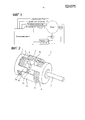
Фиг. 2 иллюстрирует внешний вид электродвигателя в перспективе.FIG. 2 illustrates a perspective view of an electric motor.
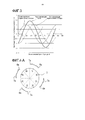
Фиг. 3 иллюстрирует график взаимосвязи угла вращения ротора и крутящего момента электродвигателя.FIG. 3 illustrates a graph of the relationship between the rotor angle and the motor torque.
Фиг. 4A и 4B изображают виды в поперечном разрезе в направлении под прямым углом к оси электродвигателя, которые иллюстрируют фазовое соотношение между ярмами статора и магнитами.FIG. 4A and 4B are cross-sectional views in a direction at right angles to the axis of the motor, which illustrate the phase relationship between the stator yokes and magnets.
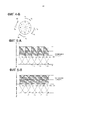
Фиг. 5A к 5C иллюстрируют крутящие моменты, действующие на ротор, при прохождении постоянного тока через катушки электродвигателя.FIG. 5A to 5C illustrate the torques acting on the rotor when direct current flows through the motor coils.
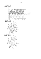
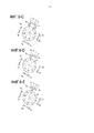
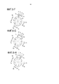
Фиг. 6A к 6I изображают виды в поперечном разрезе в направлении под прямым углом к оси электродвигателя, которые иллюстрируют фазовое соотношение между ярмами статора, магнитными датчиками и магнитами.FIG. 6A to 6I are cross-sectional views in a direction at right angles to the axis of the motor, which illustrate the phase relationship between the stator yokes, magnetic sensors, and magnets.
Фиг. 7 иллюстрирует схему последовательности операций способа управления электродвигателем.FIG. 7 illustrates a flow diagram of a method for controlling an electric motor.
Фиг. 8A и 8B иллюстрируют крутящие моменты, действующие на ротор при прохождении постоянного тока через катушки электродвигателя.FIG. 8A and 8B illustrate the torques acting on the rotor as DC passes through the motor coils.
Описание вариантов осуществленияDescription of Embodiments
[0015] Ниже подробно будет описан предпочтительный вариант осуществления настоящего изобретения со ссылкой на сопроводительные чертежи.[0015] A preferred embodiment of the present invention will be described in detail below with reference to the accompanying drawings.
[0016] Фиг. 1 иллюстрирует блок-схему устройства приведения в действие электродвигателя согласно варианту осуществления настоящего изобретения, и Фиг. 2 иллюстрирует внешний вид электродвигателя в перспективе. Следует отметить, что некоторые компоненты иллюстрированы в разрезе в целях объяснения.[0016] FIG. 1 illustrates a block diagram of an electric motor driving apparatus according to an embodiment of the present invention, and FIG. 2 illustrates a perspective view of an electric motor. It should be noted that some components are illustrated in sectional view for purposes of explanation.
[0017] Ротор 3 включает в себя магнит 2 и управляется с возможностью вращения посредством схемы 13 управления (контроллера). Магнит 2 сформирован в виде цилиндра и разделен, в направлении границы, на секции, каждая из которых имеет внешнюю границу, причем каждая секция имеет полярность, отличную от смежных секций. В этом варианте осуществления, магнит 2 разделен на восемь секций, то есть, на восемь намагниченных секций, но количество полюсов может быть равно, например, четырем или двенадцати.[0017] The
[0018] Первая катушка 4 расположена на одном конце магнита 2 в направлении оси.[0018] The
[0019] Первое ярмо 6 статора, которое состоит из магнитно-мягкого материала, размещено напротив внешней границы магнита 2, причем между первым ярмом 6 статора и внешней границей имеется зазор. Первое ярмо 6 статора включает в себя множество первых магнитных частей 6a, тянущихся от цилиндрической основной части в направлении оси и расположенных в направлении границы на предварительно определенных интервалах. Первые магнитные части 6a возбуждаются посредством подачи питания на первую катушку 4.[0019] The
[0020] Первая катушка 4, первое ярмо 6 статора и магнит 2 размещенный напротив первых магнитных частей 6a, вместе составляют первый блок статора.[0020] The
[0021] Вторая катушка 5 расположена на конце, размещенном напротив другого конца в направлении оси, в котором прикреплена первая катушка 4 магнита 2.[0021] The second coil 5 is located at an end located opposite the other end in the axis direction in which the
[0022] Второе ярмо 7 статора, которое состоит из магнитно-мягкого материала, размещено напротив внешней границы магнита 2, причем между вторым ярмом 7 статора и внешней границей находится зазор. Второе ярмо 7 статора включает в себя множество вторых магнитных частей 7a, тянущихся от основной части цилиндрической формы в направлении оси и расположенных в направлении границы на предварительно определенных интервалах. Вторые магнитные части 7a возбуждаются посредством запитывания второй катушки 5.[0022] A
[0023] Вторая катушка 5, второе ярмо 7 статора и магнит 2, размещенный напротив вторых магнитных частей 7a, вместе составляют второй блок статора.[0023] The second coil 5, the
[0024] Переключение полюса (полюса N/полюса S), возбужденного посредством первых магнитных частей 6a и вторых магнитных частей 7a позволяет выполнять изменение крутящего момента, передаваемого на ротор 3.[0024] Switching the pole (pole N / pole S) excited by the first
[0025] Первый магнитный датчик (первый обнаруживающий элемент) 8, второй магнитный датчик (второй обнаруживающий элемент) 9, третий магнитный датчик (третий обнаруживающий элемент) 10 и четвертый магнитный датчик (четвертый обнаруживающий элемент) 11 вместе составляют обнаруживающий механизм. Каждый магнит является элементом на эффекте холла, который обнаруживает магнитный поток магнита 2 и прикреплен к кожуху 12 двигателя.[0025] The first magnetic sensor (first detecting element) 8, the second magnetic sensor (second detecting element) 9, the third magnetic sensor (third detecting element) 10 and the fourth magnetic sensor (fourth detecting element) 11 together constitute the detecting mechanism. Each magnet is an element on the effect of the hall, which detects the magnetic flux of the
[0026] Кожух 12 двигателя осуществляет крепление и поддержание первого ярма 6 статора и второго ярма 7 статора таким образом, чтобы первые магнитные части 6a и вторые магнитные части 7a были расположены под электрическим углом, равным приблизительно 90 градусов относительно фазы намагничивания магнита 2.[0026] The
[0027] Термин электрический угол, используемый в настоящем документе, означает угол, выраженный посредством использования одного периода магнитной силы магнита 2, который равен 360 градусам. Если количество полюсов ротора 3 равно M, и механический угол равен θ0, то электрический угол может быть выражен посредством следующего уравнения.[0027] The term electric angle, as used herein, means an angle expressed by using one period of the magnetic force of
θ=θ0×M/2θ = θ0 × M / 2
[0028] Поскольку количество полюсов, намагничиваемых в этом варианте осуществления, равно восьми, электрический угол в 90 градусов равен механическому углу в 22,5 градусов.[0028] Since the number of poles magnetized in this embodiment is eight, the electrical angle of 90 degrees is equal to the mechanical angle of 22.5 degrees.
[0029] Ниже будет описано функционирование режима переключения питания на основе обратной связи с использованием электрического угла.[0029] The operation of the power switching mode based on feedback using the electric angle will be described below.
[0030] Фиг. 3 иллюстрирует взаимосвязь между углом вращения ротора 3 и крутящим моментом электродвигателя 1 при прохождении постоянного тока через катушки электродвигателя 1. Горизонтальная ось представляет электрический угол, а вертикальная ось - крутящий момент двигателя, соответственно. Крутящий момент, вызывающий вращение ротора 3 по часовой стрелке, определен как положительный.[0030] FIG. 3 illustrates the relationship between the rotation angle of the
[0031] Фиг. 4A и 4B изображают виды в поперечном разрезе в направлении под прямым углом к оси электродвигателя, которые иллюстрируют фазовое соотношение между каждым ярмом статора и магнитом 2.[0031] FIG. 4A and 4B are cross-sectional views in a direction at right angles to the axis of the motor, which illustrate the phase relationship between each yoke of the stator and
[0032] Предполагается, что положительный ток, проходящий через первую катушку 4, производит намагничивание первых магнитных частей 6a, и положительный ток, проходящий через вторую катушку 5, производит намагничивание вторых магнитных частей 7a.[0032] It is assumed that a positive current passing through the
[0033] Фаза в состоянии, иллюстрированном на Фиг. 4A, обозначена как «a» на Фиг. 3. Фиг. 4A иллюстрирует состояние, в котором расстояние от центров намагниченных полюсов до первых магнитных частей 6a и расстояние от центров полюсов до вторых магнитных частей 7a являются одинаковыми. В состоянии, иллюстрированном на Фиг. 4A, генерируется сила, поддерживающая фазу вращения, но не генерируется движущая сила вращения. Причина состоит в том, что полюса S магнита 2 притягиваются посредством первых магнитных частей 6a и вторых магнитных частей 7a и, таким образом, остаются в таком состоянии.[0033] The phase in the state illustrated in FIG. 4A is designated as “a” in FIG. 3. FIG. 4A illustrates a state in which the distance from the centers of the magnetized poles to the first
[0034] Вторые магнитные части 7a возбуждаются таким образом, чтобы становиться полюсами S из состояния, иллюстрированного на Фиг. 4A, что вызывает вращение ротора 3 для его перехода в состояние, иллюстрированное на Фиг. 4B.[0034] The second
[0035] На Фиг. 4B, так же, как и в состоянии, иллюстрированном на Фиг. 4A, генерируется сила, поддерживающая фазу вращения, но движущая сила вращения не генерируется. Более конкретно, полюса S и полюса N магнита 2 притягиваются посредством первых магнитных частей 6a и вторых магнитных частей 7a, соответственно, и остаются в таком состоянии.[0035] In FIG. 4B, as in the state illustrated in FIG. 4A, a force supporting the rotation phase is generated, but a driving rotation force is not generated. More specifically, the poles S and the poles N of the
[0036] Таким же способом, как было описано выше, может производиться непрерывное вращение ротора 3 посредством переключения направлений подачи питания на первую катушку 4 и на вторую катушку 5 для переключения полярностей первых магнитных частей 6a и вторых магнитных частей 7a.[0036] In the same manner as described above, the
[0037] Переключение полюсов, возбужденных посредством первых магнитных частей 6a и вторых магнитных частей 7a в момент времени, в котором такая движущая сила вращения не генерируется, далее в настоящем документе упоминается как переключение подачи питания с электрическим углом опережения по фазе равным 0 градусам. Переключение полюсов, возбужденных посредством первых магнитных частей 6a и вторых магнитных частей 7a в более ранний момент времени, чем такой момент времени, далее в настоящем документе упоминается как переключение возбуждения с электрическим углом опережения по фазе равным γ градусов.[0037] The switching of the poles excited by the first
[0038] Фиг. 5A по 5C иллюстрируют графики, иллюстрирующие угол вращения ротора в виде горизонтальной оси и крутящий момент двигателя, генерируемый при подаче питания на первую катушку 4 и вторую катушку 5, в виде вертикальной оси. Горизонтальная ось выражена посредством электрического угла.[0038] FIG. 5A to 5C illustrate graphs illustrating the rotation angle of the rotor in the form of a horizontal axis and the motor torque generated when power is supplied to the
[0039] L1 является кривой крутящего момента, наблюдаемой если направление подачи питания относительно первой катушки 4 является положительным, и направление подачи питания относительно второй катушки 5 является положительным. L2 является кривой крутящего момента, наблюдаемой, если направление подачи питания относительно первой катушки 4 является положительным, и направление подачи питания относительно второй катушки 5 является обратным. L3 является кривой крутящего момента, наблюдаемой, если направление подачи питания относительно первой катушки 4 является обратным, и направление подачи питания относительно второй катушки 5 является обратным. L4 является кривой крутящего момента, наблюдаемой, когда направление подачи питания относительно первой катушки 4 является обратным, и направление подачи питания относительно второй катушки 5 является положительным.[0039] L1 is the torque curve observed if the direction of power supply relative to the
[0040] Фиг. 5A иллюстрирует состояние, наблюдаемое если электрический угол опережения по фазе равен 0 градусов. Однако последовательное переключение направления подачи питания относительно каждой катушки в такой момент времени не дает большой мощности в качестве мощности электродвигателя 1. Причина состоит в том, что крутящий момент двигателя, как обозначено наклонными частями и жирной линией, имеет чрезвычайно малую фазу, наблюдаемой непосредственно перед переключением направления подачи питания.[0040] FIG. 5A illustrates the state observed if the electrical phase advance angle is 0 degrees. However, sequentially switching the direction of the power supply relative to each coil at such a moment of time does not give much power as the power of electric motor 1. The reason is that the motor torque, as indicated by the inclined parts and the bold line, has an extremely small phase observed immediately before switching power supply directions.
[0041] Фиг. 5B иллюстрирует состояние, наблюдаемое, если электрический угол опережения по фазе равен 45 градусов. В этом состоянии крутящий момент электродвигателя, генерируемый при переключении направления подачи питания, максимизирован.[0041] FIG. 5B illustrates the state observed if the electrical phase advance angle is 45 degrees. In this state, the motor torque generated by switching the direction of power supply is maximized.
[0042] Переключение направления подачи питания относительно каждой катушки с электрическим углом опережения по фазе равным 90 градусов при более раннем моменте времени дает крутящий момент двигателя, обозначенный наклонными частями, как иллюстрировано на Фиг. 5C. Полученный в результате крутящий момент имеет числовое значение, подобное значению, полученному при значении электрического угла опережения по фазе равном 0 градусов. Это означает, что большая движущая сила вращения не может быть получена.[0042] Switching the power supply direction relative to each coil with an electric phase angle of 90 degrees at an earlier point in time gives the engine torque indicated by the inclined parts, as illustrated in FIG. 5C. The resulting torque has a numerical value similar to the value obtained when the electric phase angle is 0 degrees. This means that a large driving force of rotation cannot be obtained.
[0043] В этом варианте осуществления может быть получена большая движущая сила вращения, даже если направление подачи питания переключается посредством размещения каждого магнитного датчика, относительно каждого ярма статора, в его соответствующем положении, описанном ниже.[0043] In this embodiment, a large driving force of rotation can be obtained even if the power supply direction is switched by placing each magnetic sensor relative to each yoke of the stator in its corresponding position described below.
[0044] Со ссылкой на Фиг. 6A по 6I будут описаны фактические этапы функционирования электродвигателя 1, где состоянием по умолчанию является состоянием, иллюстрированным на Фиг. 6A.[0044] With reference to FIG. 6A through 6I, actual operation steps of the motor 1 will be described, where the default state is the state illustrated in FIG. 6A.
[0045] (1) Вращение по часовой стрелке[0045] (1) Clockwise Rotation
[0046] (1-i) Приведение в движение с малым углом опережения по фазе[0046] (1-i) Driving with a small phase advance angle
[0047] Будет дано объяснение этапов функционирования при вращении ротора 3 по часовой стрелке (первый режим подачи питания). Эти операции выполняются посредством переключения состояния возбуждения каждой первой магнитной части 6a посредством выходного сигнала, сгенерированного посредством первого магнитного датчика 8, и посредством переключения состояния возбуждения каждой первой магнитной части 7a посредством выходного сигнала, сгенерированного посредством второго магнитного датчика 9. Направление по часовой стрелке, в котором вращается ротор 3, определено как первое направление вращения.[0047] An explanation will be given of the stages of operation when the
[0048] Каждое направление подачи питания переключается в следующей комбинации.[0048] Each power supply direction is switched in the following combination.
[0049] Если первый магнитный датчик 8 обнаруживает полюс S магнита 2, то каждая первая магнитная часть 6a возбуждается таким образом, чтобы стать полюсом N. Если первый магнитный датчик 8 обнаруживает полюс N магнита 2, то каждая первая магнитная часть 6a возбуждается таким образом, чтобы стать полюсом S.[0049] If the first
[0050] Если второй магнитный датчик 9 обнаруживает полюс S магнита 2, то каждая вторая магнитная часть 7a возбуждается таким образом, чтобы стать полюсом S. Если второй магнитный датчик 9 обнаруживает полюс N магнита 2, то каждая вторая магнитная часть 7a возбуждается таким образом, чтобы стать полюсом N.[0050] If the second
[0051] В состоянии, иллюстрированном на Фиг. 6A, каждый первый магнитный датчик 8 и второй магнитный датчик 9 обнаруживают полюс S магнита 2. В результате, каждая первая магнитная часть 6a возбуждается таким образом, чтобы стать полюсом N, а каждая вторая магнитная часть 7a - полюсом S, соответственно, производя силу вращения по часовой стрелке как в роторе 3, так и в магните 2.[0051] In the state illustrated in FIG. 6A, each first
[0052] При вращении ротора 3 по часовой стрелке из состояния, иллюстрированного на Фиг. 6A, центр Q1 намагниченного полюса магнита 2 и центр каждой первой магнитной части 6a располагаются друг напротив друга, как иллюстрировано на Фиг. 6B.[0052] When the
[0053] При вращении ротора 3 по часовой стрелке из состояния, иллюстрированного на Фиг. 6B, расстояние от центра Q1 намагниченного полюса магнита 2 до первой магнитной части 6a и расстояние от центра Q2 полюса магнита 2, где полярность намагничивания этого полюса является обратной по сравнению с центром Q1 ко второй магнитной части 7a, становятся, как иллюстрировано на Фиг. 6C, одинаковыми.[0053] When the
[0054] Первый магнитный датчик 8 расположен таким образом, что момент времени переключения возбуждения каждой первой магнитной части 6a относительно положения вращения ротора 3 находится в пределах диапазона электрических углов опережения по фазе от 0 до 45 градусов, когда полюс, возбуждаемый посредством каждой первой магнитной части 6a, переключается на основе выходных данных из первого магнитного датчика 8. Эта конструкция позволяет первому магнитному датчику 8 обнаруживать полюс N магнита 2 во время перехода из состояния, иллюстрированного на Фиг. 6B, в состояние, иллюстрированное на Фиг. 6C. При этом переходе, на первую катушку 4 подается питание таким образом, чтобы каждая первая магнитная часть 6a возбуждалась таким образом, чтобы стать полюсом S. Кроме того, как только второй магнитный датчик 9 обнаруживает полюс S магнита 2, на вторую катушку 5 подается питание таким образом, чтобы каждая вторая магнитная часть 7a возбуждалась таким образом, чтобы стать полюсом S, производя силу вращения по часовой стрелке как в роторе 3, так и в магните 2.[0054] The first
[0055] При вращении ротора 3 по часовой стрелке из состояния, иллюстрированного на Фиг. 6C, центр Q2 намагниченного полюса магнита 2 и центр второй магнитной части 7a расположены друг напротив друга, как иллюстрировано на Фиг. 6D.[0055] When the
[0056] При вращении ротора 3 по часовой стрелке из состояния, иллюстрированного на Фиг. 6D, расстояние от центра Q2 намагниченного полюса магнита 2 до первой магнитной части 6a и расстояние от центра Q2 до второй магнитной части 7a становятся, как иллюстрировано на Фиг. 6E, одинаковыми.[0056] When the
[0057] Второй магнитный датчик 9 расположен таким образом, что момент времени переключения возбуждения каждой второй магнитной части 7a относительно положения вращения ротора 3 находится в пределах диапазона электрических углов опережения по фазе от 0 до 45 градусов, когда полюс, возбуждаемый посредством каждой второй магнитной части 7a, переключается на основе выходных данных из второго магнитного датчика 9. Эта конструкция позволяет второму магнитному датчику 9 обнаруживать полюс N магнита 2 во время перехода из состояния, иллюстрированного на Фиг. 6D, в состояние, иллюстрированное на Фиг. 6E. При этом переходе, на вторую катушку 5 подается питание таким образом, что каждая вторая магнитная часть 7a возбуждается таким образом, чтобы стать полюсом N. Кроме того, как только первый магнитный датчик 8 обнаруживает полюс N магнита 2, на первую катушку 4 подается питание таким образом, что каждая первая магнитная часть 6a возбуждается таким образом, чтобы стать полюсом S, вызывая возникновение силы вращения по часовой стрелке как в роторе 3, так и в магните 2.[0057] The second
[0058] Как было описано выше, подача питания последовательно переключается, чтобы вызвать непрерывное вращение ротора 3 и магнита 2 по часовой стрелке.[0058] As described above, the power supply is switched sequentially to cause the
[0059] Первый магнитный датчик 8 расположен таким образом, что момент времени переключения возбуждения каждой первой магнитной части 6a относительно положения вращения ротора 3 находится в пределах диапазона электрических углов опережения по фазе от 0 до 45 градусов, когда полюс, возбуждаемый посредством каждой первой магнитной части 6a, переключается на основе выходных данных из первого магнитного датчика 8. Это означает, что первый магнитный датчик 8 размещен в положении, в котором величина угла опережения по фазе от положения, в котором электрический угол опережения по фазе от момента времени переключения возбуждения каждой первой магнитной части 6a равен 0 градусов, меньше, чем величина угла запаздывания от положения, в котором электрический угол опережения по фазе от момента времени переключения возбуждения каждой первой магнитной части 6a равен 90 градусов. Второй магнитный датчик 9 расположен таким образом, что момент времени переключения возбуждения каждой второй магнитной части 7a относительно положения вращения ротора 3 находится в пределах диапазона электрических углов опережения по фазе от 0 до 45 градусов, когда полюс, возбуждаемый посредством каждой второй магнитной части 7a, переключается на основе выходных данных второго магнитного датчика 9. Это означает, что второй магнитный датчик 9 размещен в положении, в котором величина угла опережения по фазе от положения, в котором электрический угол опережения по фазе от момента времени переключения возбуждения каждой второй магнитной части 7a равен 0 градусов, меньше, чем величина угла запаздывания от положения, в котором электрический угол опережения по фазе от момента времени переключения возбуждения каждой второй магнитной части 7a равен 90 градусов. Эти конструкции приводят к уменьшенному отклонению в фазе, по сравнению с фазой, наблюдаемой в состоянии, в котором возбуждение поддерживается без переключения направления подачи питания каждой катушки, даже если направление подачи питания каждой катушки переключается на основе выходных данных каждого магнитного датчика. Следовательно, не наблюдается большого различия между фазой ротора 3 и магнита 2 в отношении шагового приведения в движение, и фазой, которая наблюдается в отношении приведения в действие посредством переключения подачи питания на каждую катушку на основе выходных данных из каждого магнитного датчика. Следовательно, плавное переключение функционирования может быть выполнено без вибрации или колебания, даже если выполняется переключение шагового приведения в действие и бесщеточного приведения в действие, в котором выходные данные каждого датчика контролируются на основе обратной связи. Приведение в действие с таким электрическим углом опережения по фазе является желательным, особенно если приведение в действие начинается с состояния остановки, или если выполняется переключение из состояния приведения в действие в состояние остановки.[0059] The first
[0060] (1-ii) Приведение в действие с большим углом опережения по фазе[0060] (1-ii) Acting with a large phase advance angle
[0061] Чем быстрее становится скорость вращения ротора 3, тем медленнее становится скорость, в которой выполняется намагничивание каждой магнитной части посредством противодействующей электродвижущей силы или индуктивного компонента. Следовательно, может быть получена большая движущая сила вращения посредством переключения направления подачи питания на каждую катушку относительно положения вращения ротора 3 в более ранний момент времени.[0061] The faster the rotational speed of the
[0062] Будет дано объяснение этапов функционирования вращения ротора 3 по часовой стрелке (второго режима подачи питания). Эти этапы функционирования выполняются посредством переключения состояния возбуждения каждой первой магнитной части 6a на основе выходного сигнала, сгенерированного из третьего магнитного датчика 10, и посредством переключения состояния возбуждения каждой второй магнитной части 7a на основе выходного сигнала, сгенерированного из четвертого магнитного датчика 11.[0062] An explanation will be given of the operation steps of rotating the
[0063] Каждое направление подачи питания переключается в следующей комбинации.[0063] Each power supply direction is switched in the following combination.
[0064] Если третий магнитный датчик 10 обнаруживает полюс S магнита 2, то каждая первая магнитная часть 6a возбуждается таким образом, чтобы стать полюсом N. Если третий магнитный датчик 10 обнаруживает полюс N магнита 2, то каждая первая магнитная часть 6a возбуждается таким образом, чтобы стать полюсом S.[0064] If the third
[0065] Если четвертый магнитный датчик 11 обнаруживает полюс S магнита 2, то каждая вторая магнитная часть 7a возбуждается таким образом, чтобы стать полюсом S. Если четвертый магнитный датчик 11 обнаруживает полюс N магнита 2, то каждая вторая магнитная часть 7a возбуждается таким образом, чтобы стать полюсом N.[0065] If the fourth
[0066] В состоянии, иллюстрированном на Фиг. 6A, каждый третий магнитный датчик 10 и четвертый магнитный датчик 11 обнаруживают полюс S магнита 2. В результате, каждая первая магнитная часть 6a возбуждается таким образом, чтобы стать полюсом N, а каждая вторая магнитная часть 7a - полюсом S, соответственно, вызывая возникновение силы вращения по часовой стрелке как в роторе 3, так и в магните 2.[0066] In the state illustrated in FIG. 6A, every third
[0067] При вращении ротора 3 по часовой стрелке из состояния, иллюстрированного на Фиг. 6A, центр Q1 намагниченного полюса магнита 2 и центр каждой первой магнитной части 6a размещаются друг напротив друга, как иллюстрировано на Фиг. 6B.[0067] When the
[0068] Третий магнитный датчик 10 расположен таким образом, чтобы момент времени переключения возбуждения каждой первой магнитной части 6a относительно положения вращения ротора 3 находился в пределах диапазона электрических углов опережения по фазе 45-90 градусов, когда полюс, возбуждаемый посредством каждой первой магнитной части 6a, переключается на основе выходных данных третьего магнитного датчика 10. Эта конструкция обеспечивает возможность обнаружения третьим магнитным датчиком 10 полюса N магнита 2 во время перехода из состояния, иллюстрированного на Фиг. 6A, в состояние, иллюстрированное на Фиг. 6B. При этом переходе, на первую катушку 4 подается питание таким образом, чтобы каждая первая магнитная часть 6a возбуждалась таким образом, чтобы стать полюсом S. Кроме того, как только четвертый магнитный датчик 11 обнаруживает полюс S магнита 2, на вторую катушку 5 подается питание таким образом, чтобы каждая вторая магнитная часть 7a возбуждалась таким образом, чтобы стать полюсом S, вызывая возникновение силы вращения по часовой стрелке как в роторе 3, так и в магните 2.[0068] The third
[0069] При вращении ротора 3 по часовой стрелке из состояния, иллюстрированного на Фиг. 6B, центр Q2 намагниченного полюса магнита 2 и центр второй магнитной части 7a располагаются друг напротив друга, как иллюстрировано на Фиг. 6D, через состояние, иллюстрированное на Фиг. 6C.[0069] When the
[0070] Четвертый магнитный датчик 11 расположен таким образом, что момент времени переключения возбуждения каждой второй магнитной части 7a относительно положения вращения ротора 3, находится в пределах диапазона электрических углов опережения по фазе 45-90 градусов, если полюс, возбуждаемый посредством каждой второй магнитной части 7a, переключается на основе выходных данных четвертого магнитного датчика 11. Эта конструкция позволяет четвертому магнитному датчику 11 обнаруживать полюс N магнита 2 во время перехода из состояния, иллюстрированного на Фиг. 6C, в состояние, иллюстрированное на Фиг. 6D. При этом переходе на вторую катушку 5 подается питание таким образом, что каждая вторая магнитная часть 7a возбуждается таким образом, чтобы стать полюсом N. Кроме того, как только третий магнитный датчик 10 обнаруживает полюс N магнита 2, на первую катушку 4 подается питание таким образом, что каждая первая магнитная часть 6a возбуждается таким образом, чтобы стать полюсом S, вызывая возникновение силы вращения по часовой стрелке как в роторе 3, так и в магните 2.[0070] The fourth
[0071] Как было описано выше, осуществляется последовательное переключение подачи питания, чтобы вызвать непрерывное вращение ротора 3 и магнита 2 по часовой стрелке.[0071] As described above, the power supply is sequentially switched to cause the
[0072] Третий магнитный датчик 10 расположен таким образом, что момент времени переключения возбуждения каждой первой магнитной части 6a относительно положения вращения ротора 3, находится в пределах диапазона электрических углов опережения по фазе 45-90 градусов, если полюс, возбуждаемый посредством каждой первой магнитной части 6a, переключается на основе выходных данных третьего магнитного датчика 10. Это означает, что третий магнитный датчик 10 размещен в положении, в котором величина угла опережения по фазе от положения, в котором электрический угол опережения по фазе от момента времени переключения возбуждения каждой первой магнитной части 6a равен 0 градусов, больше, чем величина угла запаздывания от положения, в котором электрический угол опережения по фазе от момента времени переключения возбуждения каждой первой магнитной части 6a равен 90 градусов. Четвертый магнитный датчик 11 расположен таким образом, что момент времени переключения возбуждения каждой второй магнитной части 7a относительно положения вращения ротора 3 находится в пределах диапазона электрических углов опережения по фазе 45-90 градусов, когда полюс, возбуждаемый посредством каждой второй магнитной части 7a, переключается на основе выходных данных четвертого магнитного датчика 11. Это означает, что четвертый магнитный датчик 11 размещен в положении, в котором величина угла опережения по фазе от положения, в котором электрический угол опережения по фазе от момента времени переключения возбуждения каждой второй магнитной части 7a равен 0 градусов, больше, чем величина угла запаздывания от положения, в котором электрический угол опережения по фазе от момента времени переключения возбуждения каждой второй магнитной части 7a равен 90 градусов. Эта конструкция дает большую движущую силу вращения в связи с тем, что при вращении ротора 3 с высокой скоростью, момент времени, в который выполняется намагничивание каждой второй магнитной части 7a, является моментом времени, в котором электрический угол опережения по фазе достигает, по существу, 45 градусов. Следовательно, приведение в действие с таким электрическим углом опережения по фазе, является желательным, особенно при вращении ротора 3 по часовой стрелке с высокой скоростью.[0072] The third
[0073] (2) Вращение против часовой стрелки[0073] (2) Counterclockwise rotation
[0074] (2-i) Приведение в действие с малым углом опережения по фазе[0074] (2-i) Acting with a small phase advance angle
[0075] Будет дано объяснение этапов функционирования вращения ротора 3 против часовой стрелки (третьего режима подачи питания). Эти этапы функционирования выполняются посредством переключения состояния возбуждения каждой первой магнитной части 6a посредством выходного сигнала, сгенерированного из третьего магнитного датчика 10, и посредством переключения состояния возбуждения каждой второй магнитной части 7a посредством выходного сигнала, сгенерированного из четвертого магнитного датчика 11. Направление против часовой стрелки, в котором вращается ротор 3 и которое является обратным направлением относительно первого направления вращения, определено как второе направление вращения.[0075] An explanation will be given of the steps of the rotation of the
[0076] Каждое направление подачи питания переключается в следующей комбинации.[0076] Each power supply direction is switched in the following combination.
[0077] Если третий магнитный датчик 10 обнаруживает полюс S магнита 2, то каждая первая магнитная часть 6a возбуждается таким образом, чтобы стать полюсом N. Если третий магнитный датчик 10 обнаруживает полюс N магнита 2, то каждая первая магнитная часть 6a возбуждается таким образом, чтобы стать полюсом N.[0077] If the third
[0078] Если второй магнитный датчик 9 обнаруживает полюс S магнита 2, то каждая вторая магнитная часть 7a возбуждается таким образом, чтобы стать полюсом N. Если второй магнитный датчик 9 обнаруживает полюс N магнита 2, то каждая вторая магнитная часть 7a возбуждается таким образом, чтобы стать полюсом S.[0078] If the second
[0079] В состоянии, иллюстрированном на Фиг. 6A, каждый третий магнитный датчик 10 и четвертый магнитный датчик 11 обнаруживают полюс S магнита 2. В результате, каждая первая магнитная часть 6a возбуждается таким образом, чтобы стать полюсом S, а каждая вторая магнитная часть 7a - полюсом N, соответственно, вызывая возникновение силы вращения против часовой стрелки как в роторе 3, так и в магните 2.[0079] In the state illustrated in FIG. 6A, every third
[0080] При вращении ротора 3 против часовой стрелки из состояния, иллюстрированного на Фиг. 6A, центр Q1 намагниченного полюса магнита 2 и центр каждой второй магнитной части 7a размещаются друг напротив друга, как иллюстрировано на Фиг. 6F.[0080] When the
[0081] При вращении ротора 3 против часовой стрелки из состояния, иллюстрированного на Фиг. 6F, расстояния от центра Q1 намагниченного полюса магнита 2 до второй магнитной части 7a и расстояние от центра Q3 полюса магнита 2, где полярность намагничивания этого полюса является обратной по сравнению с центром Q1, до первой магнитной части 6a, становятся, как иллюстрировано на Фиг. 6G, одинаковыми.[0081] When the
[0082] Четвертый магнитный датчик 11 расположен таким образом, что момент времени переключения возбуждения каждой второй магнитной части 7a относительно положения вращения ротора 3 находится в пределах диапазона электрических углов опережения по фазе от 0 до 45 градусов, когда полюс, возбуждаемый посредством каждой второй магнитной части 7a, переключается на основе выходных данных четвертого магнитного датчика 11. Эта конструкция позволяет четвертому магнитному датчику 11 обнаруживать полюс N магнита 2 во время перехода из состояния, иллюстрированного на Фиг. 6F, в состояние, иллюстрированное на Фиг. 6G. При этом переходе, на вторую катушку 5 подается питание таким образом, что каждая вторая магнитная часть 7a возбуждается таким образом, чтобы стать полюсом S. Кроме того, как только третий магнитный датчик 10 обнаруживает полюс S магнита 2, на первую катушку 4 подается питание таким образом, что каждая первая магнитная часть 6a возбуждается таким образом, чтобы стать полюсом S, вызывая возникновение силы вращения против часовой стрелки как в роторе 3, так и в магните 2.[0082] The fourth
[0083] При вращении ротора 3 против часовой стрелки из состояния, иллюстрированного на Фиг. 6G, центр Q3 намагниченного полюса магнита 2 и центр первой магнитной части 6a располагаются друг напротив друга, как иллюстрировано на Фиг. 6H.[0083] When the
[0084] При вращении ротора 3 против часовой стрелки из состояния, иллюстрированного на Фиг. 6H, расстояния от центра Q3 намагниченного полюса магнита 2 до первой магнитной части 6a и расстояние от центра Q3 до второй магнитной части 7a становятся, как иллюстрировано на Фиг. 61, одинаковыми.[0084] When the
[0085] Третий магнитный датчик 10 расположен таким образом, что момент времени переключения возбуждения каждой первой магнитной части 6a относительно положения вращения ротора 3, находится в пределах диапазона электрических углов опережения по фазе от 0 до 45 градусов, когда полюс, возбуждаемый посредством каждой первой магнитной части 6a, переключается на основе выходных данных третьего магнитного датчика 10. Эта конструкция позволяет третьему магнитному датчику 9 обнаруживать полюс N магнита 2 во время перехода из состояния, иллюстрированного на Фиг. 6H, в состояние, иллюстрированное на Фиг. 61. При этом переходе, первая катушка 4 запитывается таким образом, что каждая первая магнитная часть 6a возбуждается таким образом, чтобы стать полюсом N. Кроме того, как только четвертый магнитный датчик 11 обнаруживает полюс N магнита 2, на вторую катушку 5 подается питание таким образом, что каждая вторая магнитная часть 7a возбуждается таким образом, чтобы стать полюсом S, вызывая возникновение силы вращения против часовой стрелки как в роторе 3, так и в магните 2.[0085] The third
[0086] Как было описано выше, питание последовательно переключается, чтобы вызывать непрерывное вращение ротора 3 и магнита 2 против часовой стрелки.[0086] As described above, the power is switched sequentially to cause the
[0087] Третий магнитный датчик 10 расположен таким образом, что момент времени переключения возбуждения каждой первой магнитной части 6a относительно положения вращения ротора 3, находится в пределах диапазона электрических углов опережения по фазе от 0 до 45 градусов, если полюс, возбуждаемый посредством каждой первой магнитной части 6a, переключается на основе выходных данных третьего магнитного датчика 10. Четвертый магнитный датчик 11 расположен таким образом, что момент времени переключения возбуждения каждой второй магнитной части 7a относительно положения вращения ротора 3, находится в пределах диапазона электрических углов опережения по фазе от 0 до 45 градусов, если полюс, возбуждаемый посредством каждой второй магнитной части 7a, переключается на основе выходных данных четвертого магнитного датчика 11. Эти конструкции приводят к уменьшенному отклонению в фазе по сравнению с фазой, наблюдаемой в состоянии, в котором возбуждение поддерживается без переключения направления подачи питания каждой катушки, даже если направление подачи питания каждой катушки переключается на основе выходных данных каждого магнитного датчика. Следовательно, не наблюдается большой разницы между фазой ротора 3 и магнитом 2 в случае нормального шагового приведения в действие, и фазой, которая наблюдается в случае приведения в действие посредством переключения подачи питания на каждую катушку на основе выходных данных каждого магнитного датчика. Следовательно, плавное переключение этапов функционирования может быть выполнено без вибрации или колебания, даже если выполняется переключение шагового приведения в действие и бесщеточного приведения в действие, в котором выходные данные каждого датчика управляются на основе обратной связи. Приведение в действие с таким электрическим углом опережения по фазе является желательным, особенно если приведение в действие начинается с состояния остановки, или если выполняется переключение из состояния приведения в действие в состояние остановки.[0087] The third
[0088] (2 ii) Приведение в действие с большим углом опережения по фазе[0088] (2 ii) Acting with a large phase advance angle
[0089] Чем быстрее становится скорость вращения ротора 3, тем медленнее становится скорость, при которой каждая магнитная часть намагничивается посредством встречной электродвижущей силы или индуктивного компонента. Следовательно, может быть получена большая движущая сила вращения посредством переключения направления подачи питания каждой катушки относительно положения вращения ротора 3 в более ранний момент времени.[0089] The faster the rotational speed of the
[0090] Будет дано объяснение этапов функционирования вращения ротора 3 против часовой стрелки (четвертого режима подачи питания). Эти этапы функционирования выполняются посредством переключения состояния возбуждения каждой первой магнитной части 6a на основе выходного сигнала, генерируемого первым магнитным датчиком 8 и посредством переключения состояния возбуждения каждой второй магнитной части 7 на основе выходного сигнала, генерируемого вторым магнитным датчиком 9.[0090] An explanation will be given of the steps in the rotation of the
[0091] Каждое направление подачи питания переключается в следующей комбинации.[0091] Each direction of power supply is switched in the following combination.
[0092] Если первый магнитный датчик 8 обнаруживает полюс S магнита 2, то каждая первая магнитная часть 6a возбуждается таким образом, чтобы стать полюсом S. Если первый магнитный датчик 8 обнаруживает полюс N магнита 2, то каждая первая магнитная часть 6a возбуждается таким образом, чтобы стать полюсом N.[0092] If the first
[0093] Если второй магнитный датчик 9 обнаруживает полюс S магнита 2, то каждая вторая магнитная часть 7a возбуждается таким образом, чтобы стать полюсом N. Если второй магнитный датчик 9 обнаруживает полюс N магнита 2, то каждая вторая магнитная часть 7a возбуждается таким образом, чтобы стать полюсом S.[0093] If the second
[0094] В состоянии, иллюстрированном на Фиг. 6A, каждый первый магнитный датчик 8 и второй магнитный датчик 9 обнаруживают полюс S магнита 2. В результате, каждая первая магнитная часть 6a возбуждается таким образом, чтобы стать полюсом S, а каждая вторая магнитная часть 7a - полюсом N, соответственно, вызывая возникновение силы вращения против часовой стрелки как в роторе 3, так и в магните 2.[0094] In the state illustrated in FIG. 6A, each first
[0095] При вращении ротора 3 по часовой стрелке из состояния, иллюстрированного на Фиг. 6A, центр Q1 намагниченного полюса магнита 2 и центр каждой второй магнитной части 7a размещаются друг напротив друга, как иллюстрировано на Фиг. 6F.[0095] When the
[0096] Второй магнитный датчик 9 расположен таким образом, что момент времени переключения возбуждения каждой второй магнитной части 7a относительно положения вращения ротора 3, находится в пределах диапазона электрических углов опережения по фазе 45-90 градусов, если полюс, возбуждаемый посредством каждой второй магнитной части 7a, переключается на основе выходных данных второго магнитного датчика 9. Эта конструкция позволяет второму магнитному датчику 9 обнаруживать полюс N магнита 2 во время перехода из состояния, иллюстрированного на Фиг. 6A, в состояние, иллюстрированное на Фиг. 6F. При этом переходе, на вторую катушку 5 подается питание таким образом, что каждая вторая магнитная часть 7a возбуждается таким образом, чтобы стать полюсом S. Кроме того, как только первый магнитный датчик 8 обнаруживает полюс S магнита 2, первая катушка 4 запитывается таким образом, что каждая первая магнитная часть 6a возбуждается таким образом, чтобы стать полюсом S, вызывая возникновение силы вращения против часовой стрелки как в роторе 3, так и в магните 2.[0096] The second
[0097] При вращении ротора 3 против часовой стрелки из состояния, иллюстрированного на Фиг. 6F, центр Q3 намагниченного полюса магнита 2 и центр первой магнитной части 6a расположены друг напротив друга, как иллюстрировано на Фиг. 6H, через состояние, иллюстрированное на Фиг. 6G.[0097] When the
[0098] Первый магнитный датчик 8 расположен таким образом, что момент времени переключения возбуждения каждой первой магнитной части 6a относительно положения вращения ротора 3, находится в пределах диапазона электрических углов опережения по фазе 45-90 градусов, если полюс, возбуждаемый посредством каждой первой магнитной части 6a, переключается на основе выходных данных из первого магнитного датчика 8. Эта конструкция позволяет первому магнитному датчику 8 обнаруживать полюс N магнита 2 во время перехода из состояния, иллюстрированного на Фиг. 6G, в состояние, иллюстрированное на Фиг. 6H. При этом переходе, первая катушка 4 запитывается таким образом, что каждая первая магнитная часть 6a возбуждается таким образом, чтобы стать полюсом N. Кроме того, как только второй магнитный датчик 9 обнаруживает полюс N магнита 2, на вторую катушку 5 подается питание таким образом, что каждая вторая магнитная часть 7a возбуждается таким образом, чтобы стать полюсом S, вызывая возникновение силы вращения против часовой стрелки как в роторе 3, так и в магните 2.[0098] The first
[0099] Как было описано выше, выполняется последовательное переключение подачи питания, чтобы вызвать возникновение непрерывного вращения ротора 3 и магнита 2 против часовой стрелки.[0099] As described above, sequentially switching the power supply is performed to cause a continuous rotation of the
[0100] Первый магнитный датчик 8 расположен таким образом, что момент времени переключения возбуждения каждой первой магнитной части 6a относительно положения вращения ротора 3, находится в пределах диапазона электрических углов опережения по фазе 45-90 градусов, если полюс, возбуждаемый посредством каждой первой магнитной части 6a, переключается на основе выходных данных из первого магнитного датчика 8. Второй магнитный датчик 9 расположен таким образом, что момент времени переключения возбуждения каждой второй магнитной части 7a относительно положения вращения ротора 3 находится в пределах диапазона электрических углов опережения по фазе 45-90 градусов, если полюс, возбуждаемый посредством каждой второй магнитной части 7a, переключается на основе выходных данных второго магнитного датчика 9. Эта конструкция дает большую движущую силу вращения в связи с тем, что, при вращении ротора 3 с высокой скоростью, момент времени, в который выполняется намагничивание каждой магнитной части, является моментом времени, в котором электрический угол опережения по фазе достигает, по существу, 45 градусов. Следовательно, приведение в действие с таким электрическим углом опережения по фазе является желательным, особенно при вращении ротора 3 против часовой стрелки с высокой скоростью.[0100] The first
[0101] Как было описано выше, в случае вращения по часовой стрелке, каждый датчик располагается следующим образом. Первый магнитный датчик 8 располагается таким образом, что момент времени переключения возбуждения каждой первой магнитной части 6a относительно положения вращения ротора 3 находится в пределах диапазона электрических углов опережения по фазе от 0 до 45 градусов, если полюс, возбуждаемый посредством каждой первой магнитной части 6a, переключается на основе выходных данных из первого магнитного датчика 8.[0101] As described above, in the case of clockwise rotation, each sensor is arranged as follows. The first
[0102] Второй магнитный датчик 9 располагается таким образом, что момент времени переключения возбуждения каждой второй магнитной части 7a относительно положения вращения ротора 3, находится в пределах диапазона электрических углов опережения по фазе от 0 до 45 градусов, если полюс, возбуждаемый посредством каждой второй магнитной части 7a, переключается на основе выходных данных второго магнитного датчика 9.[0102] The second
[0103] Третий магнитный датчик 10 расположен таким образом, что момент времени переключения возбуждения каждой первой магнитной части 6a относительно положения вращения ротора 3 находится в пределах диапазона электрических углов опережения по фазе 45-90 градусов, если полюс, возбуждаемый посредством каждой первой магнитной части 6a, переключается на основе выходных данных третьего магнитного датчика 10.[0103] The third
[0104] Четвертый магнитный датчик 11 расположен таким образом, что момент времени переключения возбуждения каждой второй магнитной части 7a относительно положения вращения ротора 3 находится в пределах диапазона электрических углов опережения по фазе 45-90 градусов, если полюс, возбуждаемый посредством каждой второй магнитной части 7a, переключается на основе выходных данных четвертого магнитного датчика 11.[0104] The fourth
[0105] С другой стороны, в случае вращения против часовой стрелки, каждый магнитный датчик расположен следующим образом. Первый магнитный датчик 8 расположен таким образом, что момент времени переключения возбуждения каждой первой магнитной части 6a относительно положения вращения ротора 3 находится в пределах диапазона электрических углов опережения по фазе 45-90 градусов, если полюс, возбуждаемый посредством каждой первой магнитной части 6a, переключается на основе выходных данных из первого магнитного датчика 8.[0105] On the other hand, in the case of counterclockwise rotation, each magnetic sensor is arranged as follows. The first
[0106] Второй магнитный датчик 9 расположен таким образом, что момент времени переключения возбуждения каждой второй магнитной части 7a относительно положения вращения ротора 3 находится в пределах диапазона электрических углов опережения по фазе 45-90 градусов, если полюс, возбуждаемый посредством каждой второй магнитной части 7a, переключается на основе выходных данных второго магнитного датчика 9.[0106] The second
[0107] Третий магнитный датчик 10 расположен таким образом, что момент времени переключения возбуждения каждой первой магнитной части 6a относительно положения вращения ротора 3 находится в пределах диапазона электрических углов опережения по фазе от 0 до 45 градусов, если полюс, возбуждаемый посредством каждой первой магнитной части 6a, переключается на основе выходных данных третьего магнитного датчика 10.[0107] The third
[0108] Четвертый магнитный датчик 11 расположен таким образом, что момент времени переключения возбуждения каждой второй магнитной части 7a относительно положения вращения ротора 3 находится в пределах диапазона электрических углов опережения по фазе от 0 до 45 градусов, если полюс, возбуждаемый посредством каждой второй магнитной части 7a, переключается на основе выходных данных четвертого магнитного датчика 11.[0108] The fourth
[0109] С практической точки зрения, каждый магнитный датчик должен быть расположен в подходящем положении, в котором может быть получена большая движущая сила вращения, с учетом таких факторов, как ошибки намагничивания магнита 2, ошибки размеров датчика и ошибки ярма статора.[0109] From a practical point of view, each magnetic sensor should be located in a suitable position in which a large driving force of rotation can be obtained, taking into account factors such as magnetization errors of
[0110] С учетом таких факторов, в случае вращения по часовой стрелке, каждый магнитный датчик предпочтительно расположен следующим образом. Первый магнитный датчик 8 предпочтительно расположен таким образом, что момент времени переключения возбуждения первого блока статора находится в пределах диапазона электрического угла опережения по фазе от 14,4 до 33,6 градусов. Третий магнитный датчик 10 предпочтительно расположен таким образом, что момент времени переключения возбуждения каждой первой магнитной части 6a, находится в пределах диапазона электрического угла опережения по фазе от 56,4 до 75,6 градусов. Второй магнитный датчик 9 предпочтительно расположен таким образом, что момент времени переключения возбуждения каждой второй магнитной части 7a находится в пределах диапазона электрического угла опережения по фазе от 14,4 до 33,6 градусов. Четвертый магнитный датчик 11 предпочтительно расположен таким образом, что момент времени переключения возбуждения каждой второй магнитной части 7a находится в пределах диапазона электрического угла опережения по фазе от 56,4 до 75,6 градусов.[0110] Given such factors, in the case of clockwise rotation, each magnetic sensor is preferably arranged as follows. The first
[0111] С другой стороны, в случае вращения против часовой стрелки, каждый магнитный датчик предпочтительно расположен следующим образом. Первый магнитный датчик 8 предпочтительно расположен таким образом, что момент времени переключения возбуждения каждой первой магнитной части 6a находится в пределах диапазона электрического угла опережения по фазе от 56,4 до 75,6 градусов. Третий магнитный датчик 10 предпочтительно расположен таким образом, что момент времени переключения возбуждения каждой первой магнитной части 6a находится в пределах диапазона электрического угла опережения по фазе от 14,4 до 33,6 градусов. Второй магнитный датчик 9 предпочтительно расположен таким образом, что момент времени переключения возбуждения каждой второй магнитной части 7a находится в пределах диапазона электрического угла опережения по фазе от 56,4 до 75,6 градусов. Четвертый магнитный датчик 11 предпочтительно расположен таким образом, что момент времени переключения возбуждения каждой второй магнитной части 7a находится в пределах диапазона электрического угла опережения по фазе от 14,4 до 33,6 градусов.[0111] On the other hand, in the case of counterclockwise rotation, each magnetic sensor is preferably arranged as follows. The first
[0112] Кроме того, следует учитывать, что необходимо избегать ситуации, в которой характеристики вращения в направлении как по часовой стрелке, так и против часовой стрелки, потеряны. Другими словами, каждый магнитный датчик должен быть расположен таким образом, чтобы средняя точка линии, соединяющей первый магнитный датчик 8 и третий магнитный датчик 10, была размещена в положении, в котором момент времени переключения возбуждения каждой первой магнитной части 6a достигает электрического угла опережения по фазе в 45 градусов. Аналогично, каждый магнитный датчик должен быть расположен таким образом, чтобы средняя точка линии, соединяющей второй магнитный датчик 9 и четвертый магнитный датчик 11, была размещена в положении, в котором момент времени переключения возбуждения каждой второй магнитной части 7a достигал электрического угла опережения по фазе в 45 градусов.[0112] In addition, it should be borne in mind that it is necessary to avoid a situation in which the rotation characteristics in the clockwise and counterclockwise directions are lost. In other words, each magnetic sensor must be positioned so that the midpoint of the line connecting the first
[0113] В этом варианте осуществления используются два различных блока датчика. Один является блоком, включающим в себя первый магнитный датчик 8 и третий магнитный датчик 10. Другой является блоком, включающим в себя второй магнитный датчик 9 и четвертый магнитный датчик 11. В случае вращения по часовой стрелке, первый магнитный датчик 8 размещается в положении, в котором момент времени переключения возбуждения каждой первой магнитной части 6a достигает электрического угла опережения по фазе в 21 градус, а третий магнитный датчик 10 находится в положении, в котором момент времени переключения возбуждения каждой первой магнитной части 6a достигает электрического угла опережения по фазе в 69 градусов, соответственно. Второй магнитный датчик 9 размещен в положении, в котором момент времени переключения возбуждения каждой второй магнитной части 7a достигает электрического угла опережения по фазе в 21 градус, а четвертый магнитный датчик 11 в положении, в котором момент времени переключения возбуждения каждой второй магнитной части 7a достигает электрического угла опережения по фазе в 69 градусов, соответственно.[0113] In this embodiment, two different sensor units are used. One is a block including a first
[0114] Теперь, со ссылкой на схему последовательности операций из Фиг. 7, будет описан способ управления приведением в действие электродвигателя 1.[0114] Now, with reference to the flowchart of FIG. 7, a method for controlling the driving of an electric motor 1 will be described.
[0115] Во-первых, предполагается, что установлена величина A приводного вращения.[0115] First, it is assumed that the drive rotation value A is set.
[0116] На этапе S1, выбирается направление вращения ротора 3. Процесс переходит на этап S2, если направлением вращения является направление по часовой стрелке, или на этап S102, если направлением вращения является направление против часовой стрелки.[0116] In step S1, the rotational direction of the
[0117] На этапе S2, выполняется подача питания в первом режиме подачи питания. Более конкретно, возбуждение каждой первой магнитной части 6a и каждой второй магнитной части 7a переключается на основе выходных данных из первого магнитного датчика 8 и второго магнитного датчика 9, соответственно, чтобы вызвать вращение ротора 3 и магнита 2 по часовой стрелке.[0117] In step S2, power is supplied in the first power supply mode. More specifically, the excitation of each first
[0118] На этапе S3, определяется скорость вращения ротора 3. Скорость вращения ротора 3 может быть измерена посредством использования каждого магнитного датчика или посредством использования известных детекторов скорости (не иллюстрированных на чертеже). Если скорость вращения меньше, чем предварительно определенная скорость, то процесс переходит на этап S4, или если скорость вращения равна или больше, чем такая предварительно определенная скорость, процесс переходит на этап S5.[0118] In step S3, the rotational speed of the
[0119] На этапе S4, определяется величина приводного вращения ротора 3. Если общая величина вращения достигает A величины приводного вращения, которая меньше предварительно определенной величины B, то процесс переходит на этап S7.[0119] In step S4, a drive rotation value of the
[0120] На этапе S5, выполняется подача питания во втором режиме подачи питания. Более конкретно, возбуждение каждой первой магнитной части 6a и каждой второй магнитной части 7a переключается на основе выходных данных третьего магнитного датчика 10 и четвертого магнитного датчика 11, соответственно, чтобы вызвать вращение ротора 3 и магнита 2 по часовой стрелке.[0120] In step S5, power is supplied in the second power supply mode. More specifically, the excitation of each first
[0121] На этапе S6, определяется величина приводного вращения ротора 3. Если общая величина вращения достигает величины A приводного вращения, которая меньше предварительно определенной величины B, то процесс переходит на этап S7.[0121] In step S6, the drive rotation value of the
[0122] На этапе S7, выполняется подача питания во втором режиме подачи питания. Более конкретно, возбуждение каждой первой магнитной части 6a и каждой второй магнитной части 7a переключается на основе выходных данных третьего магнитного датчика 10 и четвертого магнитного датчика 11, соответственно, чтобы вызвать вращение ротора 3 и магнита 2 против часовой стрелки. Во время этого вращения против часовой стрелки, ротор 3 и магнит 2 резко замедляются вследствие передаваемой на них движущей силы в направлении по часовой стрелке, но при этом, их вращение против часовой стрелки продолжается в силу их инертной массы. Альтернативно, подача питания в четвертом режиме подачи питания может быть выполнена на этапе S7.[0122] In step S7, power is supplied in the second power supply mode. More specifically, the excitation of each first
[0123] На этапе S8, определяется скорость вращения ротора 3. Если ротор 3 замедляется до предварительно определенной скорости вращения, то процесс переходит на этап S9.[0123] In step S8, the rotational speed of the
[0124] На этапе S9, режим приведения в действие переключается из бесщеточного приведения в действие, в котором направление подачи питания переключается посредством обратной связи на выходные данные, сгенерированные каждым магнитным датчиком, на шаговое приведение в действие при помощи импульсного сигнала, которое является способом приведения в действие для нормальных двухфазных шаговых электродвигателей типа PM2.[0124] In step S9, the driving mode is switched from brushless driving, in which the power supply direction is switched by feedback on the output data generated by each magnetic sensor to step-by-step driving by a pulse signal, which is a driving method for normal two-phase stepper motors type PM2.
[0125] На этапе S10, если общая величина вращения достигает величины A приводного вращения, то процесс переходит на этап S11. На этапе S11, шагового приведения в действие остановлено, чтобы остановить ротор 3 в целевом положении.[0125] In step S10, if the total rotation value reaches the drive rotation value A, the process proceeds to step S11. In step S11, the stepping actuation is stopped to stop the
[0126] На этапе S102, выполняется подача питания в третьем режиме подачи питания. Более конкретно, возбуждение каждой первой магнитной части 6a и каждой второй магнитной части 7a переключается на основе выходных данных третьего магнитного датчика 10 и четвертого магнитного датчика 11, соответственно, чтобы вызвать вращение ротора 3 и магнита 2 против часовой стрелки.[0126] In step S102, power is supplied in the third power supply mode. More specifically, the excitation of each first
[0127] На этапе S103, определяется скорость вращения ротора 3. Более конкретно, скорость вращения ротора 3 может быть измерена посредством использования каждого магнитного датчика или посредством использования известных детекторов скорости (не иллюстрированных на чертеже). Если скорость вращения меньше, чем предварительно определенная скорость, то процесс переходит на этап S104, или если скорость вращения равна или больше, чем такая предварительно определенная скорость, то процесс переходит на этап S105.[0127] In step S103, the rotational speed of the
[0128] На этапе S104, определяется величина приводного вращения ротора 3. Если общая величина вращения достигает значения A приводного вращения, которая меньше предварительно определенной величины B, то процесс переходит на этап S107.[0128] In step S104, the drive rotation value of the
[0129] На этапе S105, выполняется подача питания в четвертом режиме подачи питания. Более конкретно, возбуждение каждой первой магнитной части 6a и каждой второй магнитной части 7a переключается на основе выходных данных из первого магнитного датчика 8 и второго магнитного датчика 9, соответственно, чтобы вызвать вращение ротора 3 и магнита 2 против часовой стрелки.[0129] In step S105, power is supplied in the fourth power supply mode. More specifically, the excitation of each first
[0130] На этапе S106, определяется величина приводного вращения ротора 3. Если общая величина вращения достигает значения A приводного вращения, которая меньше предварительно определенной величины B, то процесс переходит на этап S107.[0130] In step S106, the drive rotation value of the
[0131] На этапе S107, выполняется подача питания в первом режиме подачи питания. Более конкретно, возбуждение каждой первой магнитной части 6a и каждой второй магнитной части 7a переключается на основе выходных данных из первого магнитного датчика 8 и второго магнитного датчика 9, соответственно, чтобы вызвать вращение ротора 3 и магнита 2 по часовой стрелке. Во время этого вращения по часовой стрелке, ротор 3 и магнит 2 резко замедляются вследствие подаваемой на них движущей силы в направлении против часовой стрелки, но, но при этом, их вращение против часовой стрелки продолжается в силу их инертной массы. Альтернативно, подача питания во втором режиме подачи питания может быть выполнена на этапе S107.[0131] In step S107, power is supplied in the first power supply mode. More specifically, the excitation of each first
[0132] На этапе S108, определяется скорость вращения ротора 3. Если ротор 3 замедляется до предварительно определенной скорости вращения, то процесс переходит на этап S109.[0132] In step S108, the rotational speed of the
[0133] На этапе S109, режим приведения в действие переключается с бесщеточного приведения в действие, в котором направление подачи питания переключается посредством обратной связи на основе выходных данных, сгенерированных каждым магнитным датчиком, на шаговое приведение в действие при помощи импульсного сигнала, который является способом приведения в действие нормальных двухфазных шаговых электродвигателей типа PM2.[0133] In step S109, the driving mode is switched from brushless driving, in which the power supply direction is switched by feedback based on the output data generated by each magnetic sensor to stepwise driving by a pulse signal, which is a method actuating normal two-phase stepping motors of the PM2 type.
[0134] На этапе S110, если общая величина вращения достигает величины A приводного вращения, то процесс переходит на этап S111. На этапе S1111, шаговое приведение в действие останавливается для остановки ротора 3 в целевом положении.[0134] In step S110, if the total rotation value reaches the drive rotation value A, the process proceeds to step S111. In step S1111, the stepping actuation is stopped to stop the
[0135] Как было описано выше, в этом варианте осуществления, множество углов опережения по фазе может быть установлено без времени запаздывания. Эта установка обеспечивает возможность управления приведением в действие с двумя различными углами опережения по фазе в направлениях вращения как по часовой стрелке, так и против часовой стрелки.[0135] As described above, in this embodiment, a plurality of phase advance angles can be set without delay time. This setup provides the ability to control actuation with two different phase advance angles in the directions of rotation both clockwise and counterclockwise.
[0136] Кроме того, подача питания во время перехода из положения приведения в действие в положение остановки, в фазе подачи питания с углом опережения по фазе, наблюдаемым во время обратного вращения, обеспечивает возможность быстрого замедления, которое, в свою очередь, приводит к более высокой способности управления остановкой.[0136] In addition, the power supply during the transition from the actuation position to the stop position, in the power supply phase with the advance angle in phase observed during the reverse rotation, provides the possibility of rapid deceleration, which, in turn, leads to more high stop management ability.
[0137] Несмотря на то, что настоящее изобретение было описано со ссылкой на иллюстративный вариант осуществления, следует понимать, что изобретение не ограничено раскрытым иллюстративным вариантом осуществления. Объем следующей формулы изобретения должен получить самую широкую интерпретацию для того, чтобы охватывать все такие модификации и эквивалентные структуры и функции.[0137] Although the present invention has been described with reference to an illustrative embodiment, it should be understood that the invention is not limited to the disclosed illustrative embodiment. The scope of the following claims is to be accorded the broadest interpretation so as to encompass all such modifications and equivalent structures and functions.
[0138] Настоящая заявка притязает на приоритет японской заявки на патент №2012-284086, поданной 27 декабря 2012 г., которая полностью включена в состав настоящего документа посредством ссылки.[0138] This application claims the priority of Japanese patent application No. 2012-284086, filed December 27, 2012, which is fully incorporated into this document by reference.
Промышленная применимостьIndustrial applicability
[0139] Настоящее изобретение обеспечивает устройство приведения в действие электродвигателя, которое способно устанавливать множество углов опережения по фазе без времени запаздывания и, таким образом, не вызывает потери синхронизации.[0139] The present invention provides an electric motor driving apparatus that is capable of setting a plurality of phase advance angles without lag time and thus does not cause loss of synchronization.
Список ссылочных обозначенийReference List
[0140] 1 ЭЛЕКТРОДВИГАТЕЛЬ[0140] 1 MOTOR
2 МАГНИТ2 MAGNET
3 РОТОР3 ROTOR
4 ПЕРВАЯ КАТУШКА4 FIRST COIL
5 ВТОРАЯ КАТУШКА5 SECOND COIL
6 ПЕРВОЕ ЯРМО СТАТОРА6 FIRST STATOR
6a ПЕРВАЯ МАГНИТНАЯ ЧАСТЬ6a FIRST MAGNETIC PART
7 ВТОРОЕ ЯРМО СТАТОРА7 SECOND FAIR STATOR
7a ВТОРАЯ МАГНИТНАЯ ЧАСТЬ7a SECOND MAGNETIC PART
8 ПЕРВЫЙ МАГНИТНЫЙ ДАТЧИК8 FIRST MAGNETIC SENSOR
9 ВТОРОЙ МАГНИТНЫЙ ДАТЧИК9 SECOND MAGNETIC SENSOR
10 ТРЕТИЙ МАГНИТНЫЙ ДАТЧИК10 THIRD MAGNETIC SENSOR
11 ЧЕТВЕРТЫЙ МАГНИТНЫЙ ДАТЧИК11 FOURTH MAGNETIC SENSOR
12 КОЖУХ ДВИГАТЕЛЯ12 ENGINE COVER
13 СХЕМА УПРАВЛЕНИЯ.13 CONTROL DIAGRAM.
Claims (39)
Applications Claiming Priority (3)
| Application Number | Priority Date | Filing Date | Title |
|---|---|---|---|
| JP2012-284086 | 2012-12-27 | ||
| JP2012284086A JP6120563B2 (en) | 2012-12-27 | 2012-12-27 | Motor drive device |
| PCT/JP2013/007468 WO2014103258A1 (en) | 2012-12-27 | 2013-12-19 | A motor driving apparatus |
Publications (2)
| Publication Number | Publication Date |
|---|---|
| RU2015119027A RU2015119027A (en) | 2017-01-30 |
| RU2609606C2 true RU2609606C2 (en) | 2017-02-02 |
Family
ID=51020378
Family Applications (1)
| Application Number | Title | Priority Date | Filing Date |
|---|---|---|---|
| RU2015119027A RU2609606C2 (en) | 2012-12-27 | 2013-12-19 | Motor actuating device |
Country Status (8)
| Country | Link |
|---|---|
| US (1) | US9553535B2 (en) |
| EP (1) | EP2939335B1 (en) |
| JP (1) | JP6120563B2 (en) |
| KR (1) | KR101739670B1 (en) |
| CN (1) | CN104885348B (en) |
| MY (1) | MY187913A (en) |
| RU (1) | RU2609606C2 (en) |
| WO (1) | WO2014103258A1 (en) |
Families Citing this family (10)
| Publication number | Priority date | Publication date | Assignee | Title |
|---|---|---|---|---|
| US10135369B2 (en) * | 2015-09-29 | 2018-11-20 | Microchip Technology Incorporated | Linear hall effect sensors for multi-phase permanent magnet motors with PWM drive |
| KR102146023B1 (en) * | 2016-01-07 | 2020-08-19 | 엘지이노텍 주식회사 | Motor and electronic power steering system having the same |
| JP6755665B2 (en) * | 2016-01-21 | 2020-09-16 | キヤノン株式会社 | Motor drive, motor system and imaging device |
| US10547256B2 (en) | 2017-11-08 | 2020-01-28 | Canon Kabushiki Kaisha | Motor driving apparatus capable of reliably starting motor, and method of controlling same |
| JP2019122170A (en) * | 2018-01-09 | 2019-07-22 | キヤノン株式会社 | Motor control device and method |
| US10756657B2 (en) | 2018-01-12 | 2020-08-25 | Canon Kabushiki Kaisha | Motor control apparatus and motor control method for reducing influence of magnetic fluxes from yokes |
| JP2019126244A (en) * | 2018-01-12 | 2019-07-25 | キヤノン株式会社 | Motor controller and control method |
| JP2020048335A (en) | 2018-09-19 | 2020-03-26 | キヤノン株式会社 | Actuator control device, its control method, and control program |
| CN109450134B (en) * | 2018-11-15 | 2020-12-18 | 白贺冰 | Single-phase multi-pole motor for vehicle |
| CN112666624B (en) * | 2020-12-29 | 2022-06-07 | 杭州微伽量子科技有限公司 | Quantum absolute gravimeter |
Citations (4)
| Publication number | Priority date | Publication date | Assignee | Title |
|---|---|---|---|---|
| RU2118039C1 (en) * | 1995-04-14 | 1998-08-20 | Научно-производственное предприятие "Эметрон" | Inductor motor control method |
| FR2820252A1 (en) * | 2001-01-31 | 2002-08-02 | Midi Ingenierie | BRUSHLESS MOTOR CONTROL SYSTEM |
| JP2006105652A (en) * | 2004-10-01 | 2006-04-20 | Japan Atom Energy Res Inst | High precision position detection control method by radiation-resistant rotation detector using proximity sensor, and device used for the method |
| CN104052352A (en) * | 2013-03-12 | 2014-09-17 | 佳能株式会社 | Motor drive apparatus for driving stepping motor and control method therefor |
Family Cites Families (11)
| Publication number | Priority date | Publication date | Assignee | Title |
|---|---|---|---|---|
| JPH0223092A (en) * | 1988-07-12 | 1990-01-25 | Secoh Giken Inc | Motor operated by output torque designated by ac power source |
| JPH0667259A (en) | 1992-08-24 | 1994-03-11 | Canon Inc | Optical equipment |
| JP2002023092A (en) * | 2000-07-03 | 2002-01-23 | Sharp Corp | Optical scanning device |
| JP2002359997A (en) | 2001-03-26 | 2002-12-13 | Fdk Corp | Stepper motor and driving control method therefor |
| JP4796779B2 (en) * | 2005-03-29 | 2011-10-19 | 日本電産コパル株式会社 | Stepping motor and fan including the same |
| JP5241184B2 (en) | 2007-09-14 | 2013-07-17 | キヤノン株式会社 | motor |
| JP5656354B2 (en) | 2008-10-20 | 2015-01-21 | キヤノン株式会社 | Drive device |
| JP5515426B2 (en) * | 2009-05-28 | 2014-06-11 | 日本電産株式会社 | motor |
| JP5441624B2 (en) | 2009-11-05 | 2014-03-12 | キヤノン株式会社 | Motor drive device |
| JP5574837B2 (en) | 2010-06-16 | 2014-08-20 | キヤノン株式会社 | Imaging device |
| JP2012068921A (en) * | 2010-09-24 | 2012-04-05 | Ckd Corp | Electric actuator |
-
2012
- 2012-12-27 JP JP2012284086A patent/JP6120563B2/en not_active Expired - Fee Related
-
2013
- 2013-12-19 EP EP13867328.0A patent/EP2939335B1/en not_active Not-in-force
- 2013-12-19 US US14/652,429 patent/US9553535B2/en active Active
- 2013-12-19 KR KR1020157016423A patent/KR101739670B1/en active IP Right Grant
- 2013-12-19 CN CN201380068491.7A patent/CN104885348B/en not_active Expired - Fee Related
- 2013-12-19 MY MYPI2015701231A patent/MY187913A/en unknown
- 2013-12-19 WO PCT/JP2013/007468 patent/WO2014103258A1/en active Application Filing
- 2013-12-19 RU RU2015119027A patent/RU2609606C2/en active
Patent Citations (4)
| Publication number | Priority date | Publication date | Assignee | Title |
|---|---|---|---|---|
| RU2118039C1 (en) * | 1995-04-14 | 1998-08-20 | Научно-производственное предприятие "Эметрон" | Inductor motor control method |
| FR2820252A1 (en) * | 2001-01-31 | 2002-08-02 | Midi Ingenierie | BRUSHLESS MOTOR CONTROL SYSTEM |
| JP2006105652A (en) * | 2004-10-01 | 2006-04-20 | Japan Atom Energy Res Inst | High precision position detection control method by radiation-resistant rotation detector using proximity sensor, and device used for the method |
| CN104052352A (en) * | 2013-03-12 | 2014-09-17 | 佳能株式会社 | Motor drive apparatus for driving stepping motor and control method therefor |
Also Published As
| Publication number | Publication date |
|---|---|
| CN104885348A (en) | 2015-09-02 |
| MY187913A (en) | 2021-10-28 |
| JP6120563B2 (en) | 2017-04-26 |
| CN104885348B (en) | 2017-09-05 |
| US9553535B2 (en) | 2017-01-24 |
| EP2939335B1 (en) | 2019-10-02 |
| RU2015119027A (en) | 2017-01-30 |
| KR20150086539A (en) | 2015-07-28 |
| EP2939335A4 (en) | 2016-11-02 |
| US20150326157A1 (en) | 2015-11-12 |
| KR101739670B1 (en) | 2017-05-24 |
| JP2014128143A (en) | 2014-07-07 |
| EP2939335A1 (en) | 2015-11-04 |
| WO2014103258A1 (en) | 2014-07-03 |
Similar Documents
| Publication | Publication Date | Title |
|---|---|---|
| RU2609606C2 (en) | Motor actuating device | |
| US20140354119A1 (en) | Permanent magnet-type rotating machine | |
| JP4505050B2 (en) | Step motor | |
| US9124203B2 (en) | Motor having pulse mode and brushless mode, and control method and apparatus of the motor | |
| JP5656354B2 (en) | Drive device | |
| US9136750B2 (en) | Motor capable of adjusting phase difference between output signals | |
| JP2010098922A5 (en) | Drive device | |
| JP2009189091A (en) | Linear actuator | |
| US7728469B2 (en) | Motor driving apparatus | |
| GB2305022A (en) | Starting a single phase reluctance motor | |
| JP5322501B2 (en) | Drive device and electronic device | |
| US10756657B2 (en) | Motor control apparatus and motor control method for reducing influence of magnetic fluxes from yokes | |
| JP2018078790A (en) | Startup control method of brushless three-phase synchronous electric motor | |
| JP2019071028A (en) | Motor control apparatus, motor control method, and imaging apparatus | |
| JP5511445B2 (en) | Motor and motor drive control method | |
| JP2011101480A (en) | Motor drive device | |
| JP2019122170A (en) | Motor control device and method | |
| JP2019126244A (en) | Motor controller and control method | |
| JP2021023000A (en) | motor | |
| JP6135927B2 (en) | Stepping motor driving apparatus, driving system, and driving method, and lens unit and camera having the same | |
| WO2017038859A1 (en) | Motor | |
| JP2020099169A (en) | Motor drive device and control method of the same | |
| JP2020036492A (en) | motor | |
| JP2011151908A (en) | Motor controller and optical apparatus | |
| JP2001028898A (en) | Driving device for stepping motor |