WO2014097989A1 - 内燃機関の制御装置及び燃料噴射制御方法 - Google Patents
内燃機関の制御装置及び燃料噴射制御方法 Download PDFInfo
- Publication number
- WO2014097989A1 WO2014097989A1 PCT/JP2013/083476 JP2013083476W WO2014097989A1 WO 2014097989 A1 WO2014097989 A1 WO 2014097989A1 JP 2013083476 W JP2013083476 W JP 2013083476W WO 2014097989 A1 WO2014097989 A1 WO 2014097989A1
- Authority
- WO
- WIPO (PCT)
- Prior art keywords
- fuel ratio
- fuel
- air
- injections
- control
- Prior art date
- Legal status (The legal status is an assumption and is not a legal conclusion. Google has not performed a legal analysis and makes no representation as to the accuracy of the status listed.)
- Ceased
Links
Images


Classifications
-
- F—MECHANICAL ENGINEERING; LIGHTING; HEATING; WEAPONS; BLASTING
- F02—COMBUSTION ENGINES; HOT-GAS OR COMBUSTION-PRODUCT ENGINE PLANTS
- F02D—CONTROLLING COMBUSTION ENGINES
- F02D41/00—Electrical control of supply of combustible mixture or its constituents
- F02D41/02—Circuit arrangements for generating control signals
- F02D41/14—Introducing closed-loop corrections
- F02D41/1438—Introducing closed-loop corrections using means for determining characteristics of the combustion gases; Sensors therefor
- F02D41/1473—Introducing closed-loop corrections using means for determining characteristics of the combustion gases; Sensors therefor characterised by the regulation method
- F02D41/1475—Regulating the air fuel ratio at a value other than stoichiometry
-
- F—MECHANICAL ENGINEERING; LIGHTING; HEATING; WEAPONS; BLASTING
- F02—COMBUSTION ENGINES; HOT-GAS OR COMBUSTION-PRODUCT ENGINE PLANTS
- F02D—CONTROLLING COMBUSTION ENGINES
- F02D41/00—Electrical control of supply of combustible mixture or its constituents
- F02D41/30—Controlling fuel injection
- F02D41/38—Controlling fuel injection of the high pressure type
- F02D41/40—Controlling fuel injection of the high pressure type with means for controlling injection timing or duration
- F02D41/402—Multiple injections
-
- Y—GENERAL TAGGING OF NEW TECHNOLOGICAL DEVELOPMENTS; GENERAL TAGGING OF CROSS-SECTIONAL TECHNOLOGIES SPANNING OVER SEVERAL SECTIONS OF THE IPC; TECHNICAL SUBJECTS COVERED BY FORMER USPC CROSS-REFERENCE ART COLLECTIONS [XRACs] AND DIGESTS
- Y02—TECHNOLOGIES OR APPLICATIONS FOR MITIGATION OR ADAPTATION AGAINST CLIMATE CHANGE
- Y02T—CLIMATE CHANGE MITIGATION TECHNOLOGIES RELATED TO TRANSPORTATION
- Y02T10/00—Road transport of goods or passengers
- Y02T10/10—Internal combustion engine [ICE] based vehicles
- Y02T10/40—Engine management systems
Definitions
- the present invention relates to a control device and a fuel injection control method for controlling an in-cylinder direct injection internal combustion engine.
- JP62-32242A discloses a fuel injection device that injects fuel per one rotation of an engine in a plurality of times according to the engine temperature.
- the exhaust particulate matter (PM) contained in the exhaust gas may increase depending on the operating state of the engine.
- An object of the present invention is to reduce exhaust particulates contained in exhaust.
- the control device includes a setting unit that sets a target air-fuel ratio according to the operating state of the internal combustion engine, and a calculation unit that calculates a fuel injection amount in one cycle based on the target air-fuel ratio, the intake air amount, and the engine speed. And including.
- the control unit determines whether or not the air-fuel ratio rich control is based on the target air-fuel ratio, and when the air-fuel ratio rich control is performed, the fuel injection amount becomes larger than the same air-fuel ratio stoichiometric control.
- it includes a determining unit that determines the number of injections in one cycle, and an injection valve control unit that controls the fuel injection valve based on the number of injections determined by the determining unit.
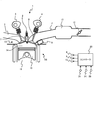
- FIG. 1 is a diagram showing an internal combustion engine according to an embodiment of the present invention.
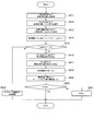
- FIG. 2 is a flowchart showing a fuel injection control method for the internal combustion engine.
- FIG. 3 is a diagram showing the relationship between the number of injections in one cycle and the air-fuel ratio.
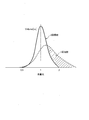
- FIG. 4 is a diagram showing the distribution of the air-fuel ratio in the combustion chamber by a plurality of fuel injections.
- FIG. 5 is a diagram showing the relationship between the engine speed and the correction coefficient for the number of injections.
- FIG. 1 is a diagram showing an internal combustion engine according to an embodiment of the present invention.
- the internal combustion engine 1 is an in-cylinder direct injection spark ignition type internal combustion engine, for example, mounted on a vehicle.
- the internal combustion engine 1 has multiple cylinders. In FIG. 1, only one cylinder is shown for convenience of explanation.
- the internal combustion engine 1 includes a cylinder head 1A and a cylinder block 1B.
- a piston 10 is housed in a cylinder 11 provided in the cylinder block 1B so as to be able to reciprocate.
- a combustion chamber 14 is defined by the wall surface of the cylinder 11, the crown surface of the piston 10, and the lower surface of the cylinder head 1A.
- an ignition plug 8 and a fuel injection valve 9 are arranged facing the combustion chamber 14.
- the fuel injection valve 9 is an in-cylinder direct injection injector.
- the fuel injection valve 9 injects fuel in one cycle by dividing it into a plurality of times.
- an intake passage 2 and an exhaust passage 3 are formed in the cylinder head 1A.
- the intake passage 2 and the exhaust passage 3 are both open.
- the opening of the exhaust passage 3 is opened and closed by an exhaust valve 7.
- the exhaust valve 7 is driven by the exhaust camshaft 5.
- the intake valve 6 is driven by the intake camshaft 4.
- the intake camshaft 4 includes a variable valve mechanism that can change the valve timing.
- the collector tank 13 is interposed in the intake passage 2.
- a throttle valve 12 is disposed on the upstream side of the intake air flow of the collector tank 13.
- Controller 20 performs opening / closing control of throttle valve 12, fuel injection control such as injection timing and injection amount of fuel injection valve 9, and ignition timing control of spark plug 8.
- the controller 20 executes each control described above based on detection signals from the throttle opening sensor 21, the crank angle sensor 22, the fuel pressure sensor 23, and the like.
- the controller 20 includes a microcomputer that includes a central processing unit (CPU), a random access memory (RAM), and an input / output interface (I / O interface).
- the controller 20 may be composed of a plurality of microcomputers.
- the controller 20 changes the number of injections of the fuel injection valve 9 in one cycle according to the fuel injection amount of the internal combustion engine 1.
- the air-fuel mixture in the combustion chamber may become non-uniform due to the air-fuel ratio control of the internal combustion engine. If ignition is performed in a non-uniform state of the air-fuel mixture, a large amount of exhaust particulate (PM) is contained in the exhaust, and the number of exhaust particulates (PMPN) may increase.
- the number of injections in one cycle is determined based on the target air-fuel ratio for each fuel injection amount.
- FIG. 2 is a view showing a flowchart of the fuel injection control method according to the embodiment of the present invention.
- FIG. 2 shows an injection number determination routine for determining the number of injections of the fuel injection valve 9 by the controller 20.
- step S911 the controller 20 calculates the intake air amount Qa to the combustion chamber 14 based on the detection signal of the throttle opening sensor 21. At the same time, the controller 20 calculates the engine rotational speed Ne based on the detection signal of the crank angle sensor 22.
- step S912 the controller 20 calculates the basic fuel injection pulse width Tp based on the intake air amount Qa and the engine rotational speed Ne.
- the injection pulse width is determined by the fuel injection amount.
- step S913 the controller 20 sets the target air-fuel ratio Target A / F according to the operating state of the internal combustion engine 1.
- the internal combustion engine 1 of the present embodiment is operated in a stratified stoichiometric combustion mode for a predetermined period from the start, and is operated in a homogeneous stoichiometric combustion mode after the predetermined period has elapsed.
- the air-fuel ratio of the internal combustion engine 1 is temporarily adjusted to the rich side in order to ensure continuity of engine torque and combustion stability.
- the controller 20 when the internal combustion engine 1 is shifted from the stratified stoichiometric combustion mode to the homogeneous stoichiometric combustion mode, the controller 20 temporarily sets the target air-fuel ratio to the rich side. In addition, even after the transition to the homogeneous stoichiometric combustion mode, the controller 20 sets the target air-fuel ratio to the rich side at the initial stage of the acceleration operation or immediately after the restart of fuel injection from the fuel cut.
- step S914 the controller 20 calculates the fuel injection pulse width Ti using the basic fuel injection pulse width Tp, the target air-fuel ratio Target A / F, and the theoretical air-fuel ratio (14.7) according to the following equation.
- step S915 the controller 20 determines whether or not the air-fuel ratio rich control is performed based on the target air-fuel ratio. For example, the controller 20 determines that the air-fuel ratio control of the internal combustion engine 1 is the air-fuel ratio rich control when the target air-fuel ratio is on the rich side smaller than the stoichiometric air-fuel ratio. When the target air-fuel ratio matches the stoichiometric air-fuel ratio, the controller 20 determines that the air-fuel ratio stoichiometric control is performed.
- step S910 when the target air-fuel ratio matches the stoichiometric air-fuel ratio, the controller 20 determines the number of injections of the fuel injection valve 9 in one cycle as the number of injections during the air-fuel ratio stoichiometric control.
- the number of injections during the air-fuel ratio stoichiometric control is set to one regardless of the fuel injection amount Ti.
- the controller 20 determines the number of injections in the air-fuel ratio rich control so that the fuel injection amount is larger than that in the same air-fuel ratio stoichiometric control. Specifically, the processing from step S916 to step S920 is executed.
- step S916 the controller 20 calculates the basic injection number N0 of the fuel injection valve 9 based on the fuel injection pulse width Ti and the target air-fuel ratio Target A / F.
- the controller 20 increases or decreases the basic injection number N0 according to the target air-fuel ratio for each fuel injection amount. That is, the controller 20 increases the basic injection number N0 as the target air-fuel ratio deviates to the rich side from the stoichiometric air-fuel ratio at the same fuel injection amount. As described above, as the number of injections of the fuel injection valve 9 is increased, the local rich in the combustion chamber 14 is improved, so that the PM contained in the exhaust gas decreases.
- the basic injection number N0 calculated by the controller 20 is the minimum number of injections necessary for improving the air-fuel ratio distribution in the combustion chamber.
- the amount of reduction in PM contained in the exhaust gas hardly decreases when the number of injections exceeds a certain number of injections. Therefore, the number of injections of the fuel injection valve 9 is reduced by setting the minimum number of injections in which the PM reduction effect in the exhaust can be obtained, and the failure of the fuel injection valve 9 due to the increase in the number of injections is reduced. Suppresses the occurrence.
- an injection control map in which the fuel injection amount, the air-fuel ratio, and the number of injections are associated with each other is recorded in the controller 20 in advance.
- the controller 20 acquires the number of injections associated with the injection control map based on the fuel injection pulse width Ti and the target air-fuel ratio Target A / F.
- the injection control map will be described later with reference to FIG.
- step S917 the controller 20 calculates a correction value N1 for the number of injections based on the engine rotational speed Ne.
- the correction value for the number of injections is hereinafter referred to as an “addition coefficient”.
- the controller 20 calculates a larger addition coefficient N1 as the engine speed Ne is lower.
- the lower the engine speed Ne the lower the fluidity of the gas in the combustion chamber and the easier it is to generate a locally rich mixture. Therefore, the non-uniformity of the air-fuel mixture in the combustion chamber can be further improved by increasing the addition coefficient as the engine speed Ne decreases.
- an injection correction map in which the engine rotation speed and the addition coefficient of the number of injections are associated with each other is recorded in the controller 20 in advance. Then, the controller 20 refers to the injection correction map and acquires the addition coefficient N1 associated with the engine speed Ne.
- the injection correction map will be described later with reference to FIG.
- step S918 the controller 20 calculates the injection number N by correcting the basic injection number N0 by the addition coefficient N1 of the injection number. Specifically, the controller 20 calculates the injection number N obtained by adding the addition coefficient N1 to the basic injection number N0.
- step S919 the controller 20 calculates the upper limit N lim of the number of injections by dividing the fuel injection pulse width Ti by the minimum injection amount (pulse width) Tmin of one time by the fuel injection valve 9. Then, the controller 20 sets an upper limit value N lim for the number of injections of the fuel injection valve 9. Thereby, since unnecessary injection by the fuel injection valve 9 can be avoided, aging can be suppressed from the viewpoint of durability of the fuel injection valve 9.
- step S920 the controller 20 determines whether or not the number of injections N exceeds the upper limit value N lim . When the number of injections N does not exceed the upper limit value N lim , the controller 20 determines the number of injections of the fuel injection valve 9 as N.
- step S921 when the number of injections N exceeds the upper limit value N lim in step S921, the controller 20 limits the number of injections of the fuel injection valve 9 to N lim .
- the controller 20 controls the fuel injection valve 9 based on the number of injections N determined in step S910, S918, or S921.
- the controller 20 determines the fuel injection pulse width of each injection (for example, the first injection and the second injection) based on the injection number N.
- the fuel injection amount Ti is injected into the combustion chamber 14 from the fuel injection valve 9 in a plurality of times according to the determined fuel injection pulse width.
- FIG. 3 is a conceptual diagram showing an injection control map in which the number of injections is associated with each injection region.
- FIG. 3 shows a first stage injection area, a second stage injection area, a third stage injection area, and a fourth stage injection area defined by the fuel injection area Ti and the target air-fuel ratio Target A / F.
- “1” is associated with the basic injection number N0 in the first-stage injection region.
- “2” is associated with the basic injection number N0 in the two-stage injection region.
- “3” is associated with the basic injection number N0 in the three-stage injection region.
- “4” is associated with the basic injection number N0 in the four-stage injection region.
- the injection control map for the same injection amount, the greater the deviation from the stoichiometric air-fuel ratio of the target air-fuel ratio to the rich side, the greater the number of injections, and the smaller the fuel injection amount Ti, the smaller the number of injections. Further, the minimum number of injections necessary for reducing PM in the exhaust is associated with each injection region.
- the injection control map is determined in advance by, for example, experimental data.
- the number of injections is set to one regardless of the fuel injection amount Ti. This is because when the air-fuel ratio is in a stoichiometric state, the PM improvement effect does not change greatly even if the number of injections is increased. However, even when the air-fuel ratio is in the stoichiometric state, the number of injections may be set to a plurality of times according to the fuel injection amount Ti.
- the controller 20 refers to the injection control map, identifies the injection region based on the fuel injection amount Ti and the target air-fuel ratio Target A / F, and sets the specified injection region. The associated number of injections is acquired. Then, the controller 20 controls the fuel injection valve 9 so as to increase the number of injections according to the target air-fuel ratio.
- FIG. 4 is a diagram showing the improvement of the air-fuel ratio distribution in the combustion chamber by increasing the number of injections of the fuel injection valve 9.
- the solid line shows the air-fuel ratio distribution of the air-fuel mixture by the three-time injection in the air-fuel ratio rich control
- the broken line shows the air-fuel ratio distribution of the air-fuel mixture by the one-time injection of the fuel injection valve 9.
- the vertical axis represents the frequency of the air-fuel ratio of the air-fuel mixture in the combustion chamber.
- the frequency peak of the air-fuel ratio in the combustion chamber is higher than in the one-time injection, and the uniformity of the fuel distribution in the combustion chamber is improved. That is, the air-fuel ratio distribution in the shaded area is improved. Thereby, PM in the gas discharged
- FIG. 5 is a conceptual diagram showing an injection correction map in which an addition coefficient N1 of the number of injections is associated with the engine speed.
- the addition coefficient N1 of the number of injections is set in the order of “0”, “1”, and “2” as the engine speed Ne decreases. That is, as the engine speed Ne is lower, a larger addition coefficient N1 is associated with the injection correction map.
- the number of injections can be increased as the engine speed Ne is lower.
- the number of injections can be increased to more reliably improve the uneven fuel distribution in the combustion chamber.
- the controller 20 determines whether or not the air-fuel ratio rich control is performed based on the target air-fuel ratio.
- the air-fuel ratio rich control is performed, the air-fuel ratio stoichiometry with the same fuel injection amount is determined.
- the number of injections in one cycle is determined so as to be greater than the control.
- the controller 20 controls the fuel injection valve 9 based on the determined number of injections.
- This increases the number of injections in one cycle based on the target air-fuel ratio for each fuel injection amount, improving the uniformity of the air-fuel mixture in the combustion chamber and reducing PM (exhaust particulates) contained in the exhaust gas. be able to.
- the controller 20 increases or decreases the number of injections according to the target air-fuel ratio.
- the number of injections can be adjusted in accordance with the non-uniformity of the air-fuel mixture in the combustion chamber that changes depending on the target air-fuel ratio.
- the controller 20 increases the number of injections of the fuel injection valve 9 as the target air-fuel ratio deviates to the rich side from the stoichiometric air-fuel ratio.
- the more the target air-fuel ratio deviates toward the rich side the more likely the air-fuel mixture in the combustion chamber becomes non-uniform. For this reason, by increasing the number of injections according to the degree of deviation of the target air-fuel ratio toward the rich side, the generation of a locally rich air-fuel mixture can be prevented more reliably.
- the number of injections of the fuel injection valve 9 is determined by the controller 20 to the minimum number of injections necessary for improving the air-fuel ratio distribution in the combustion chamber. Therefore, since the increase in the excessive frequency
- the controller 20 limits the number of fuel injection amount injections by the number of injections determined by the minimum injection amount of the fuel injection valve 9. Thereby, it is possible to prevent the fuel injection amount from being insufficient.
- the number of injections is set within an allowable range in which the minimum injection pulse is established, even if there is a variation in the fuel injection amount due to manufacturing errors, it can be within the allowable range, and combustion caused by the variation in the fuel injection amount Variations can be suppressed. Therefore, combustion stability can be improved.
- the controller 20 corrects the number of injections based on the engine speed. For this reason, the controller 20 can increase the number of injections of the fuel injection valve 9 because the fluidity of the air-fuel mixture in the combustion chamber decreases when the engine speed is low. Thereby, even when the fluidity of the air-fuel mixture in the combustion chamber is low, the air-fuel ratio distribution can be improved more reliably.
Landscapes
- Engineering & Computer Science (AREA)
- Chemical & Material Sciences (AREA)
- Combustion & Propulsion (AREA)
- Mechanical Engineering (AREA)
- General Engineering & Computer Science (AREA)
- Electrical Control Of Air Or Fuel Supplied To Internal-Combustion Engine (AREA)
Abstract
制御装置は、1サイクル中の燃料を複数回に分割して噴射する筒内直接噴射式の燃料噴射弁を有する内燃機関を制御する。制御装置は、内燃機関の運転状態に応じて目標空燃比を設定する設定部と、目標空燃比と吸入空気量と機関回転速度とに基づいて1サイクル中の燃料噴射量を算出する算出部と、を含む。そして制御装置は、目標空燃比に基づいて空燃比リッチ制御であるか否かを判定する判定部と、空燃比リッチ制御であるときは、燃料噴射量が同一の空燃比ストイキ制御よりも多くなるように1サイクル中の噴射回数を決定する決定部と、を含む。
Description
この発明は、筒内直接噴射式の内燃機関を制御する制御装置及び燃料噴射制御方法に関する。
JP62-32242Aには、機関温度に応じて機関1回転あたりの燃料を複数回に分けて噴射する燃料噴射装置が開示されている。
前述した燃料噴射装置は、燃料噴射量によって噴射回数を変更するので、機関の運転状態によっては、排気中に含まれる排気微粒子(PM:Particulate Matter)が増加する場合がある。
本発明は、このような問題点に着目してなされた。本発明の目的は、排気中に含まれる排気微粒子を低減することにある。
本発明による制御装置のひとつの態様は、1サイクル中の燃料を複数回に分割して噴射する筒内直接噴射式の燃料噴射弁を有する内燃機関を制御する制御装置である。この制御装置は、内燃機関の運転状態に応じて目標空燃比を設定する設定部と、目標空燃比と吸入空気量と機関回転速度とに基づいて1サイクル中の燃料噴射量を算出する算出部と、を含む。そして制御装置は、目標空燃比に基づいて空燃比リッチ制御であるか否かを判定する判定部と、空燃比リッチ制御であるときは、燃料噴射量が同一の空燃比ストイキ制御よりも多くなるように1サイクル中の噴射回数を決定する決定部と、決定部によって決定された噴射回数に基づいて燃料噴射弁を制御する噴射弁制御部と、を含むことを特徴とする。
以下、添付図面を参照しながら本発明の実施形態について説明する。
(第1実施形態)
図1は、本発明の実施形態における内燃機関を示す図である。
図1は、本発明の実施形態における内燃機関を示す図である。
内燃機関1は、筒内直接噴射火花点火式の内燃機関であり、例えば、車両に搭載される。内燃機関1は、多気筒を有する。なお、図1では説明の便宜上、1つの気筒だけが示されている。
内燃機関1は、シリンダヘッド1Aとシリンダブロック1Bとを含んで構成される。シリンダブロック1Bに設けられたシリンダ11には、ピストン10が往復運動可能に収められている。シリンダ11の壁面とピストン10の冠面とシリンダヘッド1Aの下面とで燃焼室14が画成される。
シリンダヘッド1Aには、点火栓8と燃料噴射弁9が燃焼室14に臨んで配置される。燃料噴射弁9は、筒内直接噴射式のインジェクタである。燃料噴射弁9は、1サイクル中の燃料を複数回に分割して噴射する。
また、シリンダヘッド1Aには、吸気通路2及び排気通路3が形成されている。吸気通路2及び排気通路3はいずれも開口している。排気通路3の開口部は、排気弁7によって開閉される。排気弁7は、排気カムシャフト5によって駆動される。
一方、吸気通路2の開口部は、吸気弁6によって開閉される。吸気弁6は、吸気カムシャフト4によって駆動される。吸気カムシャフト4は、バルブタイミングを変更可能な可変動弁機構を備える。
吸気通路2には、コレクタタンク13が介装される。コレクタタンク13の吸気流れ上流側にはスロットルバルブ12が配置される。
コントローラー20は、スロットルバルブ12の開閉制御、燃料噴射弁9の噴射タイミングや噴射量等の燃料噴射制御、及び点火栓8の点火時期制御を実行する。
コントローラー20は、スロットル開度センサー21、クランク角センサー22や燃圧センサー23等の検出信号に基づいて上記各制御を実行する。コントローラー20は、中央演算装置(CPU)、ランダムアクセスメモリ(RAM)及び入出力インターフェース(I/Oインターフェース)を備えたマイクロコンピューターで構成される。例えば、複数のマイクロコンピューターでコントローラー20を構成してもよい。
コントローラー20は、内燃機関1の燃料噴射量に応じて1サイクル中の燃料噴射弁9の噴射回数を変更する。このような燃料噴射制御においては、同じ燃料噴射量で噴射する場合であっても、内燃機関の空燃比制御によって燃焼室内の混合気が不均一になる場合がある。混合気が不均一な状態で点火すると、多量の排気微粒子(PM)が排気中に含まれてしまい、排気微粒子の数(PMPN)が増加することがある。
そこで、本発明では、燃料噴射量ごとに、目標空燃比に基づいて1サイクル中の噴射回数を決定する。
図2は、本発明の実施形態に係る燃料噴射制御方法のフローチャートを示す図である。図2では、コントローラー20による燃料噴射弁9の噴射回数を決定する噴射回数決定ルーチンが示されている。
まず、ステップS911において、コントローラー20は、スロットル開度センサー21の検出信号に基づいて燃焼室14への吸入空気量Qaを算出する。これとともにコントローラー20は、クランク角センサー22の検出信号に基づいて機関回転速度Neを算出する。
ステップS912においてコントローラー20は、吸入空気量Qaと機関回転速度Neとに基づいて、基本燃料噴射パルス幅Tpを算出する。なお、噴射パルス幅は、燃料噴射量によって決まる。
ステップS913においてコントローラー20は、内燃機関1の運転状態に応じて目標空燃比TargetA/Fを設定する。
本実施形態の内燃機関1は、始動から所定期間は成層ストイキ燃焼形態で運転され、所定期間経過後は均質ストイキ燃焼形態で運転される。内燃機関1が成層ストイキ燃焼形態から均質ストイキ燃焼形態に切り換えられるときには、機関トルクの連続性と燃焼安定性を確保するため、一時的に内燃機関1の空燃比はリッチ側に調整される。
このため、コントローラー20は、内燃機関1を成層ストイキ燃焼形態から均質ストイキ燃焼形態へ移行するときには、一時的に目標空燃比をリッチ側に設定する。また、均質ストイキ燃焼形態へ移行後においても、コントローラー20は、加速運転初期や、燃料カットからの燃料噴射の再開直後などに目標空燃比をリッチ側に設定する。
ステップS914においてコントローラー20は、次式により、基本燃料噴射パルス幅Tpと目標空燃比TargetA/Fと理論空燃比(14.7)とを用いて燃料噴射パルス幅Tiを算出する。

ステップS915においてコントローラー20は、目標空燃比に基づいて空燃比リッチ制御であるか否かを判定する。例えば、コントローラー20は、目標空燃比が理論空燃比よりも小さいリッチ側であるときは、内燃機関1の空燃比制御を空燃比リッチ制御と判定する。またコントローラー20は、目標空燃比が理論空燃比と一致したときは、空燃比ストイキ制御と判定する。
ステップS910においてコントローラー20は、目標空燃比が理論空燃比と一致したときは、1サイクル中の燃料噴射弁9の噴射回数を、空燃比ストイキ制御時の噴射回数に決定する。本実施形態では空燃比ストイキ制御時の噴射回数は、燃料噴射量Tiにかかわらず1回に設定される。
一方、コントローラー20は、目標空燃比がリッチ側であるときは、燃料噴射量が同一の空燃比ストイキ制御よりも多くなるように、空燃比リッチ制御時の噴射回数を決定する。具体的にはステップS916~ステップS920の処理を実行する。
ステップS916においてコントローラー20は、燃料噴射パルス幅Tiと、目標空燃比TargetA/Fとに基づいて、燃料噴射弁9の基本噴射回数N0を算出する。
本実施形態では、コントローラー20は、燃料噴射量ごとに、目標空燃比に応じて基本噴射回数N0を増減させる。すなわち、コントローラー20は、同一の燃料噴射量において、目標空燃比が理論空燃比よりもリッチ側へ乖離するほど、基本噴射回数N0を増やす。このように、燃料噴射弁9の噴射回数を多くするほど、燃焼室14における局所的なリッチが改善されるので、排気中に含まれるPMは減少する。
コントローラー20で算出される基本噴射回数N0は、燃焼室内の空燃比分布の改善に必要な最小限の噴射回数である。通常、排気中に含まれるPMの減少量は、一定の噴射回数を超えるとほとんど減少しなくなる。そのため、排気中のPM減少効果が得られる噴射回数のうち最小限の回数に設定することによって、燃料噴射弁9の噴射回数を少なくし、噴射回数の増加に起因する燃料噴射弁9の故障の発生を抑制する。
本実施形態では、燃料噴射量と空燃比と噴射回数とが互いに対応付けられた噴射制御マップが、コントローラー20に予め記録されている。そしてコントローラー20は、空燃比リッチ制御のときは、燃料噴射パルス幅Tiと目標空燃比TargetA/Fとに基づいて噴射制御マップに対応付けられた噴射回数を取得する。なお、噴射制御マップについては図3を参照して後述する。
ステップS917においてコントローラー20は、機関回転速度Neに基づいて噴射回数の補正値N1を算出する。なお、噴射回数の補正値は、以下「加算係数」と称する。
本実施形態では、コントローラー20は、機関回転速度Neが低いほど、大きな加算係数N1を算出する。一般的に、機関回転速度Neが低くなるほど、燃焼室内のガスの流動性が低くなって局所的にリッチな混合気が発生しやすくなる。そのため、機関回転速度Neが低くなるほど加算係数を増加させることにより、燃焼室内の混合気の不均一性をより改善させることができる。
本実施形態では、機関回転速度と噴射回数の加算係数とが互いに対応付けられた噴射補正マップが、コントローラー20に予め記録されている。そしてコントローラー20は、噴射補正マップを参照して、機関回転速度Neに対応付けられた加算係数N1を取得する。なお、噴射補正マップについては図5を参照して後述する。
ステップS918においてコントローラー20は、噴射回数の加算係数N1によって基本噴射回数N0を補正して噴射回数Nを算出する。具体的にはコントローラー20は、基本噴射回数N0に加算係数N1を加えた噴射回数Nを算出する。
ステップS919においてコントローラー20は、燃料噴射パルス幅Tiを、燃料噴射弁9による1回の最小噴射量(パルス幅)Tminにより除算して噴射回数の上限値Nlimを算出する。そしてコントローラー20は、燃料噴射弁9の噴射回数に上限値Nlimを設定する。これにより、燃料噴射弁9による必要以上の噴射を回避できるので、燃料噴射弁9の耐久性の観点から老朽化を抑えることができる。
ステップS920においてコントローラー20は、噴射回数Nが上限値Nlimを超えるか否かを判断する。そしてコントローラー20は、噴射回数Nが上限値Nlimを超えない場合には、燃料噴射弁9の噴射回数をNに決定する。
一方、ステップS921においてコントローラー20は、噴射回数Nが上限値Nlimを超える場合には、燃料噴射弁9の噴射回数をNlimに制限する。そしてコントローラー20はステップS910、S918又はS921で決定された噴射回数Nに基づいて燃料噴射弁9を制御する。
燃料噴射決定ルーチンが終了すると、例えば、図示しない他のルーチンにおいて、コントローラー20が、噴射回数Nに基づいて各噴射(例えば、1回目の噴射、2回目の噴射)の燃料噴射パルス幅を決定し、決定された燃料噴射パルス幅によって燃料噴射弁9から燃焼室14に燃料噴射量Tiが複数回に分けて噴射される。
図3は、噴射領域ごとに噴射回数が対応付けられた噴射制御マップを示す観念図である。図3には、燃料噴射領域Tiと目標空燃比TargetA/Fとによって定められた1段噴射領域、2段噴射領域、3段噴射領域、4段噴射領域がそれぞれ示されている。
1段噴射領域の基本噴射回数N0には「1」が対応付けられている。2段噴射領域の基本噴射回数N0には「2」が対応付けられている。3段噴射領域の基本噴射回数N0には「3」が対応付けられている。4段噴射領域の基本噴射回数N0には「4」が対応付けられている。
噴射制御マップでは、同一の噴射量において、目標空燃比の理論空燃比からリッチ側への乖離が大きいほど、噴射回数が大きくなり、かつ、燃料噴射量Tiが小さいほど、噴射回数が小さくなる。また、排気中のPMを減少させるのに必要な最小の噴射回数が各噴射領域に対応付けられている。噴射制御マップは、例えば、実験データなどによって予め定められている。
図3に示すように、本実施形態では、空燃比がストイキ状態(14.7)のとき、燃料噴射量Tiにかかわらず噴射回数を1回に設定している。これは、空燃比がストイキ状態である場合、噴射回数を増やしてもPM改善効果が大きく変化しないためである。ただし、空燃比がストイキ状態のときも、燃料噴射量Tiに応じて噴射回数を複数回に設定してもよい。
このように、コントローラー20は、空燃比リッチ制御であるときは、噴射制御マップを参照して、燃料噴射量Tiと目標空燃比TargetA/Fとによって噴射領域を特定し、特定された噴射領域に対応付けられた噴射回数を取得する。そしてコントローラー20は、目標空燃比に応じて噴射回数を増やすように、燃料噴射弁9を制御する。
図4は、燃料噴射弁9の噴射回数の増加による燃焼室内の空燃比の分布の改善を示す図である。
図4では、実線によって、空燃比リッチ制御での3回噴射による混合気の空燃比分布が示され、破線によって、燃料噴射弁9の1回噴射による混合気の空燃比分布が示されている。また、横軸は当量比(=14.7/目標空燃比)を示し、縦軸は燃焼室内における混合気の空燃比の度数を示す。
図4に示すように、燃料噴射弁9による3回噴射では、1回噴射に比べて燃焼室内の空燃比の度数のピークが高くなり、燃焼室内の燃料分布の均一性が向上する。すなわち、斜線部分の空燃比の分布が改善する。これにより、燃焼室14から排出されるガス中のPMを減らすことができる。
図5は、機関回転速度に応じて噴射回数の加算係数N1が対応付けられた噴射補正マップを示す観念図である。
噴射補正マップには、機関回転速度Neが低くなるほど、噴射回数の加算係数N1が「0」、「1」、「2」の順に設定されている。すなわち、機関回転速度Neが低いほど、大きな加算係数N1が噴射補正マップに対応付けられている。
このように、噴射補正マップを用いることで、機関回転速度Neが低いほど、噴射回数を多くすることができる。これにより、機関回転速度Neが低く燃焼室内のガスの流動性が低いときには、噴射回数を増やして燃焼室内の燃料分布の不均一な状態をより確実に改善させることができる。
本発明の実施形態によれば、コントローラー20は、目標空燃比に基づいて空燃比リッチ制御であるか否かを判定し、空燃比リッチ制御であるときは、燃料噴射量が同一の空燃比ストイキ制御よりも多くなるように1サイクル中の噴射回数を決定する。そしてコントローラー20は、決定された噴射回数に基づいて燃料噴射弁9を制御する。
これにより、燃料噴射量ごとに、目標空燃比に基づいて1サイクル中の噴射回数を増やすので、燃焼室内の混合気の均一度が向上し、排気中に含まれるPM(排気微粒子)を低減することができる。
本実施形態では、コントローラー20は、目標空燃比に応じて噴射回数を増減させる。これにより、目標空燃比によって変わる燃焼室内の混合気の不均一性に合わせて噴射回数を調整することができる。
また、本実施形態では、コントローラー20は、目標空燃比が理論空燃比よりもリッチ側に乖離するほど、燃料噴射弁9の噴射回数を増やす。目標空燃比がリッチ側に乖離するほど、燃焼室内の混合気が不均一になりやすくなる。このため、目標空燃比のリッチ側への乖離度に応じて噴射回数を増やすことによって、局所的にリッチな混合気の発生をより確実に防ぐことができる。
また、本実施形態では、燃料噴射弁9の噴射回数は、コントローラー20によって燃焼室内の空燃比分布の改善に必要な最小限の噴射回数に決定される。これにより、燃料噴射弁9による過剰な噴射回数の増加を抑制することができるので、燃料噴射弁9の作動劣化を抑えることができる。
また、本実施形態では、コントローラー20は、燃料噴射弁9の最小噴射量によって定められる噴射回数により、燃料噴射量の噴射回数を制限する。これにより、燃料噴射量が不足することを防ぐことができる。また、最小噴射パルスが成立する許容範囲に噴射回数が設定されるので、製造誤差による燃料噴射量にバラツキがあっても許容範囲内に収めることが可能となり、燃料噴射量のバラツキに起因する燃焼変動を抑制することができる。したがって、燃焼安定性を向上させることが可能となる。
また、本実施形態では、コントローラー20は、機関回転速度に基づいて噴射回数を補正する。このため、コントローラー20は、機関回転速度が低いときには、燃焼室内の混合気の流動性が低くなるので、燃料噴射弁9の噴射回数を増加させることが可能となる。これにより、燃焼室内の混合気の流動性が低いときにも、空燃比の分布をより確実に改善することができる。
以上、本発明の実施形態について説明したが、上記実施形態は本発明の適用例の一部を示したに過ぎず、本発明の技術的範囲を上記実施形態の具体的構成に限定する趣旨ではない。
なお、上記実施形態は、適宜組み合わせ可能である。
本願は、2012年12月20日に日本国特許庁に出願された特願2012-278427に基づく優先権を主張し、この出願の全ての内容は参照により本明細書に組み込まれる。
Claims (7)
- 1サイクル中の燃料を複数回に分割して噴射する筒内直接噴射式の燃料噴射弁を有する内燃機関の制御装置であって、
前記内燃機関の運転状態に応じて目標空燃比を設定する設定部と、
前記目標空燃比と吸入空気量と機関回転速度とに基づいて1サイクル中の燃料噴射量を算出する算出部と、
前記目標空燃比に基づいて空燃比リッチ制御であるか否かを判定する判定部と、
空燃比リッチ制御であるときは、燃料噴射量が同一の空燃比ストイキ制御よりも多くなるように1サイクル中の噴射回数を決定する決定部と、
前記決定部によって決定された噴射回数に基づいて前記燃料噴射弁を制御する噴射弁制御部と、
を含む内燃機関の制御装置。 - 請求項1に記載の機関の制御装置であって、
前記決定部は、目標空燃比に応じて噴射回数を増減させる、
内燃機関の制御装置。 - 請求項1又は請求項2に記載の機関の制御装置であって、
前記決定部は、目標空燃比が理論空燃比よりもリッチ側に乖離するほど、噴射回数を増やす、
内燃機関の制御装置。 - 請求項1から請求項3のいずれか1項に記載の機関の制御装置であって、
前記決定部によって決定される噴射回数は、燃焼室内の空燃比分布の改善に必要な最小限の噴射回数である、
内燃機関の制御装置。 - 請求項1から請求項4のいずれか1項に記載の機関の制御装置であって、
前記燃料噴射弁制御部は、前記燃料噴射弁の最小噴射量によって定められる噴射回数により、燃料噴射量の噴射回数を制限する、
内燃機関の制御装置。 - 請求項1から請求項5のいずれか1項に記載の機関の制御装置であって、
前記決定部は、機関回転速度に基づいて噴射回数を補正する、
内燃機関の制御装置。 - 1サイクル中の燃料を複数回に分割して噴射する筒内直接噴射式の燃料噴射弁を有する内燃機関の燃料噴射制御方法であって、
機関の運転状態に応じて目標空燃比を設定する設定工程と、
吸入空気量と機関回転速度と目標空燃比とに基づいて1サイクル中の燃料噴射量を算出する算出工程と、
前記目標空燃比に基づいて空燃比リッチ制御であるか否かを判定する判定工程と、
空燃比リッチ制御であるときは、燃料噴射量が同一の空燃比ストイキ制御よりも多くなるように1サイクル中の噴射回数を決定する決定工程と、
前記決定部によって決定された噴射回数に基づいて前記燃焼噴射弁を制御する噴射弁制御工程と、
を含む内燃機関の燃料噴射制御方法。
Applications Claiming Priority (2)
| Application Number | Priority Date | Filing Date | Title |
|---|---|---|---|
| JP2012-278427 | 2012-12-20 | ||
| JP2012278427A JP2016029264A (ja) | 2012-12-20 | 2012-12-20 | 内燃機関の制御装置及び燃料噴射制御方法 |
Publications (1)
| Publication Number | Publication Date |
|---|---|
| WO2014097989A1 true WO2014097989A1 (ja) | 2014-06-26 |
Family
ID=50978321
Family Applications (1)
| Application Number | Title | Priority Date | Filing Date |
|---|---|---|---|
| PCT/JP2013/083476 Ceased WO2014097989A1 (ja) | 2012-12-20 | 2013-12-13 | 内燃機関の制御装置及び燃料噴射制御方法 |
Country Status (2)
| Country | Link |
|---|---|
| JP (1) | JP2016029264A (ja) |
| WO (1) | WO2014097989A1 (ja) |
Cited By (2)
| Publication number | Priority date | Publication date | Assignee | Title |
|---|---|---|---|---|
| CN112096535A (zh) * | 2020-08-13 | 2020-12-18 | 东风汽车集团有限公司 | 发动机燃油喷射次数控制方法、系统及汽车 |
| CN112963252A (zh) * | 2021-03-18 | 2021-06-15 | 潍柴动力股份有限公司 | 一种发动机的排放控制方法、装置及设备 |
Citations (2)
| Publication number | Priority date | Publication date | Assignee | Title |
|---|---|---|---|---|
| JP2012031844A (ja) * | 2010-06-30 | 2012-02-16 | Mazda Motor Corp | 自動車搭載用ターボ過給機付ディーゼルエンジン及びディーゼルエンジンの制御方法 |
| JP2012087706A (ja) * | 2010-10-21 | 2012-05-10 | Hitachi Automotive Systems Ltd | 筒内噴射エンジンとその制御装置 |
-
2012
- 2012-12-20 JP JP2012278427A patent/JP2016029264A/ja active Pending
-
2013
- 2013-12-13 WO PCT/JP2013/083476 patent/WO2014097989A1/ja not_active Ceased
Patent Citations (2)
| Publication number | Priority date | Publication date | Assignee | Title |
|---|---|---|---|---|
| JP2012031844A (ja) * | 2010-06-30 | 2012-02-16 | Mazda Motor Corp | 自動車搭載用ターボ過給機付ディーゼルエンジン及びディーゼルエンジンの制御方法 |
| JP2012087706A (ja) * | 2010-10-21 | 2012-05-10 | Hitachi Automotive Systems Ltd | 筒内噴射エンジンとその制御装置 |
Cited By (3)
| Publication number | Priority date | Publication date | Assignee | Title |
|---|---|---|---|---|
| CN112096535A (zh) * | 2020-08-13 | 2020-12-18 | 东风汽车集团有限公司 | 发动机燃油喷射次数控制方法、系统及汽车 |
| CN112096535B (zh) * | 2020-08-13 | 2021-11-02 | 东风汽车集团有限公司 | 发动机燃油喷射次数控制方法、系统及汽车 |
| CN112963252A (zh) * | 2021-03-18 | 2021-06-15 | 潍柴动力股份有限公司 | 一种发动机的排放控制方法、装置及设备 |
Also Published As
| Publication number | Publication date |
|---|---|
| JP2016029264A (ja) | 2016-03-03 |
Similar Documents
| Publication | Publication Date | Title |
|---|---|---|
| US7747379B2 (en) | Control device of direct injection internal combustion engine | |
| US7841316B2 (en) | Controller for direct injection engine | |
| JP6167700B2 (ja) | 筒内噴射エンジンの制御装置 | |
| JP5541535B2 (ja) | 内燃機関の燃料噴射制御装置 | |
| JP2009185741A (ja) | 内燃機関の燃料噴射制御装置 | |
| JP3893909B2 (ja) | 直噴火花点火式内燃機関の制御装置 | |
| JP5637222B2 (ja) | 内燃機関の制御装置 | |
| JP6314614B2 (ja) | 筒内噴射式内燃機関の噴射制御装置 | |
| JP5273310B2 (ja) | 内燃機関の制御装置 | |
| JP5195353B2 (ja) | エンジンの始動時燃料噴射制御装置 | |
| JP2016029264A (ja) | 内燃機関の制御装置及び燃料噴射制御方法 | |
| JP2006194098A (ja) | 内燃機関の燃料噴射制御装置 | |
| CN104279112A (zh) | 内燃机的点火正时控制装置 | |
| JP5282636B2 (ja) | 内燃機関の制御装置 | |
| JP5187537B2 (ja) | 内燃機関の燃料噴射制御装置 | |
| JP4529835B2 (ja) | 内燃機関の制御装置 | |
| CN106481474A (zh) | 用于内燃发动机的控制装置 | |
| JP2010168931A (ja) | 火花点火式内燃機関の点火時期制御装置 | |
| JP4415864B2 (ja) | 内燃機関の制御装置 | |
| JP6603150B2 (ja) | 内燃機関の燃料噴射制御装置 | |
| JP2005307756A (ja) | 内燃機関の燃料噴射制御装置 | |
| JP2013087675A (ja) | 内燃機関の制御装置 | |
| JP6167659B2 (ja) | 内燃機関の燃料噴射制御装置 | |
| JP2014020205A (ja) | 内燃機関の制御装置 | |
| JP4735382B2 (ja) | 内燃機関の燃料供給制御装置 |
Legal Events
| Date | Code | Title | Description |
|---|---|---|---|
| 121 | Ep: the epo has been informed by wipo that ep was designated in this application |
Ref document number: 13866336 Country of ref document: EP Kind code of ref document: A1 |
|
| NENP | Non-entry into the national phase |
Ref country code: DE |
|
| 122 | Ep: pct application non-entry in european phase |
Ref document number: 13866336 Country of ref document: EP Kind code of ref document: A1 |
|
| NENP | Non-entry into the national phase |
Ref country code: JP |