WO2014097922A1 - 無段変速機の制御装置 - Google Patents
無段変速機の制御装置 Download PDFInfo
- Publication number
- WO2014097922A1 WO2014097922A1 PCT/JP2013/083002 JP2013083002W WO2014097922A1 WO 2014097922 A1 WO2014097922 A1 WO 2014097922A1 JP 2013083002 W JP2013083002 W JP 2013083002W WO 2014097922 A1 WO2014097922 A1 WO 2014097922A1
- Authority
- WO
- WIPO (PCT)
- Prior art keywords
- hydraulic pressure
- continuously variable
- variable transmission
- transmission mechanism
- hydraulic
- Prior art date
- Legal status (The legal status is an assumption and is not a legal conclusion. Google has not performed a legal analysis and makes no representation as to the accuracy of the status listed.)
- Ceased
Links
Images





Classifications
-
- F—MECHANICAL ENGINEERING; LIGHTING; HEATING; WEAPONS; BLASTING
- F16—ENGINEERING ELEMENTS AND UNITS; GENERAL MEASURES FOR PRODUCING AND MAINTAINING EFFECTIVE FUNCTIONING OF MACHINES OR INSTALLATIONS; THERMAL INSULATION IN GENERAL
- F16H—GEARING
- F16H61/00—Control functions within control units of change-speed- or reversing-gearings for conveying rotary motion ; Control of exclusively fluid gearing, friction gearing, gearings with endless flexible members or other particular types of gearing
- F16H61/0021—Generation or control of line pressure
- F16H61/0025—Supply of control fluid; Pumps therefor
- F16H61/0031—Supply of control fluid; Pumps therefor using auxiliary pumps, e.g. pump driven by a different power source than the engine
-
- F—MECHANICAL ENGINEERING; LIGHTING; HEATING; WEAPONS; BLASTING
- F16—ENGINEERING ELEMENTS AND UNITS; GENERAL MEASURES FOR PRODUCING AND MAINTAINING EFFECTIVE FUNCTIONING OF MACHINES OR INSTALLATIONS; THERMAL INSULATION IN GENERAL
- F16H—GEARING
- F16H61/00—Control functions within control units of change-speed- or reversing-gearings for conveying rotary motion ; Control of exclusively fluid gearing, friction gearing, gearings with endless flexible members or other particular types of gearing
- F16H61/66—Control functions within control units of change-speed- or reversing-gearings for conveying rotary motion ; Control of exclusively fluid gearing, friction gearing, gearings with endless flexible members or other particular types of gearing specially adapted for continuously variable gearings
- F16H61/662—Control functions within control units of change-speed- or reversing-gearings for conveying rotary motion ; Control of exclusively fluid gearing, friction gearing, gearings with endless flexible members or other particular types of gearing specially adapted for continuously variable gearings with endless flexible members
- F16H61/66272—Control functions within control units of change-speed- or reversing-gearings for conveying rotary motion ; Control of exclusively fluid gearing, friction gearing, gearings with endless flexible members or other particular types of gearing specially adapted for continuously variable gearings with endless flexible members characterised by means for controlling the torque transmitting capability of the gearing
-
- B—PERFORMING OPERATIONS; TRANSPORTING
- B60—VEHICLES IN GENERAL
- B60Y—INDEXING SCHEME RELATING TO ASPECTS CROSS-CUTTING VEHICLE TECHNOLOGY
- B60Y2300/00—Purposes or special features of road vehicle drive control systems
- B60Y2300/18—Propelling the vehicle
- B60Y2300/18008—Propelling the vehicle related to particular drive situations
- B60Y2300/18066—Coasting
- B60Y2300/18083—Coasting without torque flow between driveshaft and engine, e.g. with clutch disengaged or transmission in neutral
-
- F—MECHANICAL ENGINEERING; LIGHTING; HEATING; WEAPONS; BLASTING
- F02—COMBUSTION ENGINES; HOT-GAS OR COMBUSTION-PRODUCT ENGINE PLANTS
- F02D—CONTROLLING COMBUSTION ENGINES
- F02D29/00—Controlling engines, such controlling being peculiar to the devices driven thereby, the devices being other than parts or accessories essential to engine operation, e.g. controlling of engines by signals external thereto
- F02D29/02—Controlling engines, such controlling being peculiar to the devices driven thereby, the devices being other than parts or accessories essential to engine operation, e.g. controlling of engines by signals external thereto peculiar to engines driving vehicles; peculiar to engines driving variable pitch propellers
-
- F—MECHANICAL ENGINEERING; LIGHTING; HEATING; WEAPONS; BLASTING
- F16—ENGINEERING ELEMENTS AND UNITS; GENERAL MEASURES FOR PRODUCING AND MAINTAINING EFFECTIVE FUNCTIONING OF MACHINES OR INSTALLATIONS; THERMAL INSULATION IN GENERAL
- F16H—GEARING
- F16H59/00—Control inputs to control units of change-speed- or reversing-gearings for conveying rotary motion
- F16H59/14—Inputs being a function of torque or torque demand
- F16H59/18—Inputs being a function of torque or torque demand dependent on the position of the accelerator pedal
- F16H2059/186—Coasting
-
- Y—GENERAL TAGGING OF NEW TECHNOLOGICAL DEVELOPMENTS; GENERAL TAGGING OF CROSS-SECTIONAL TECHNOLOGIES SPANNING OVER SEVERAL SECTIONS OF THE IPC; TECHNICAL SUBJECTS COVERED BY FORMER USPC CROSS-REFERENCE ART COLLECTIONS [XRACs] AND DIGESTS
- Y02—TECHNOLOGIES OR APPLICATIONS FOR MITIGATION OR ADAPTATION AGAINST CLIMATE CHANGE
- Y02T—CLIMATE CHANGE MITIGATION TECHNOLOGIES RELATED TO TRANSPORTATION
- Y02T10/00—Road transport of goods or passengers
- Y02T10/60—Other road transportation technologies with climate change mitigation effect
Definitions
- the present invention relates to a control device for a continuously variable transmission mounted on a vehicle that stops and restarts a driving force source.
- the belt type continuously variable transmission is supplied with hydraulic pressure generated by a mechanical oil pump driven by an engine.
- the primary pulley and the secondary pulley are supplied with pulley pressure (primary pulley pressure and secondary pulley pressure) that uses this oil pressure as the original pressure.
- the belt is clamped by these pulley pressures, and by controlling these pulley pressures, the groove width of each pulley is changed, and a shift is performed.
- the clutch engagement force is set to be higher than the belt engagement force.
- a so-called clutch fuse control is performed to reduce the temperature.
- JP1998-002390A increases the clutch engagement force and the belt pressing force when a clutch slip is detected, and controls the clutch engagement force and the belt pressing force when no slip is detected. What controls the decrease is known.
- coast stop control In recent years, for the purpose of improving fuel performance, so-called coast stop control is performed in which the engine is stopped before the vehicle stops, as well as when the vehicle stops. Even during coast stop control, if torque is input from the drive wheels due to sudden braking, stepping up, etc., belt slip may occur, so it is desirable to perform clutch fuse control even during coast stop control .
- the actual oil pressure obtained by the oil pressure control does not necessarily match the indicated oil pressure due to variations.
- the fastening force of the clutch is greater than the fastening force of the belt, and the belt slips due to the torque input from the drive wheels.
- the clutch engagement force is increased.
- the present invention has been made in view of such problems, and an object of the present invention is to provide a continuously variable transmission control device capable of preventing belt slippage even when the engine is stopped by coast stop control. To do.
- a continuously variable transmission mechanism mounted on a vehicle and capable of changing a gear ratio by changing a winding diameter of a power transmission belt that is clamped by hydraulic pressure supplied to a pulley, and a continuously variable transmission
- a frictional engagement element that is connected to the mechanism and transmits the driving force of the driving force source to the driving wheels in an intermittent manner, a coast stop control unit that stops the driving force source in a running state of the vehicle, and a non-driven by the driving force source.
- a first hydraulic pressure source that supplies hydraulic pressure to the step transmission mechanism and the frictional engagement element; a second hydraulic pressure source that is arranged in parallel with the first hydraulic pressure source and that can supply hydraulic pressure to the continuously variable transmission mechanism and the frictional engagement element; A first urging portion having a first urging force that is arranged in the fastening element and acts in a direction to reduce the first transmission capacity obtained by the hydraulic pressure from the first or second hydraulic power source; and a continuously variable transmission mechanism; Obtained by hydraulic pressure from first or second hydraulic source A second urging portion having a second urging force that works in the direction of increasing the transmission capacity, and at least one of the first urging force and the second urging force stops when the driving force of the driving force source stops.
- the hydraulic pressure source supplies the hydraulic pressure
- the second transmission capacity is set to be equal to or higher than the first transmission capacity in the entire hydraulic pressure region supplied by the second hydraulic pressure source.
- a continuously variable transmission mechanism mounted on a vehicle and capable of changing a gear ratio by changing a winding diameter of a power transmission belt sandwiched by hydraulic pressure supplied to a pulley;
- a friction engagement element that is connected to the transmission mechanism and transmits the driving force of the driving force source to the driving wheels in an intermittent manner, and a first hydraulic pressure source that is driven by the driving force source and supplies hydraulic pressure to the continuously variable transmission mechanism and the friction engagement element
- a second hydraulic pressure source arranged in parallel with the first hydraulic pressure source and capable of supplying hydraulic pressure to the continuously variable transmission mechanism and the frictional engagement element, and stopping the driving force source in the traveling state of the vehicle
- a control device for driving the second hydraulic power source during execution of the coast stop control and a control device for the continuously variable transmission that is provided on the discharge oil passage of the second hydraulic power source and is supplied from the second hydraulic power source.
- the hydraulic power is transmitted to the continuously variable transmission mechanism. Characterized in that it comprises a regulating unit for regulating the hydraulic below the power transmission capacity of the
- the second transmission capacity of the continuously variable transmission mechanism is set to be equal to or greater than the first transmission capacity of the auxiliary transmission mechanism.
- FIG. 1 is a schematic configuration diagram of a vehicle equipped with a continuously variable transmission according to an embodiment of the present invention.
- FIG. 2 is an explanatory diagram showing an example of the configuration of the transmission controller according to the embodiment of the present invention.
- FIG. 3 is an explanatory diagram of a hydraulic circuit centering on the hydraulic control circuit of the embodiment of the present invention.
- FIG. 4 is an explanatory diagram for coast stop control according to the embodiment of the present invention.
- FIG. 5 is an explanatory diagram showing the relationship between the hydraulic pressure and the transmission torque capacity according to the embodiment of the present invention.
- FIG. 6 is an explanatory diagram of the primary pulley of the variator according to the embodiment of the present invention.
- FIG. 1 is a schematic configuration diagram of a vehicle equipped with a continuously variable transmission according to an embodiment of the present invention.
- FIG. 2 is an explanatory diagram showing an example of the configuration of the transmission controller according to the embodiment of the present invention.
- FIG. 3 is an explanatory diagram of a hydraulic circuit center
- FIG. 7 is an explanatory diagram of the frictional engagement element of the auxiliary transmission mechanism according to the embodiment of the present invention.
- FIG. 8 is an explanatory diagram showing the relationship between the hydraulic pressure and the transmission torque capacity according to the embodiment of the present invention.
- FIG. 9 is an explanatory diagram showing the relationship between the hydraulic pressure and the transmission torque capacity according to the embodiment of the present invention.
- FIG. 1 is a schematic configuration diagram of a vehicle equipped with a continuously variable transmission according to an embodiment of the present invention.
- This vehicle includes an engine 1 as a power source.
- the output rotation of the engine 1 is via a torque converter 2 with a lock-up clutch, a first gear train 3, a continuously variable transmission (hereinafter simply referred to as "transmission 4"), a second gear train 5, and a final reduction gear 6.
- transmission 4" continuously variable transmission
- the second gear train 5 is provided with a parking mechanism 8 that mechanically locks the output shaft of the transmission 4 at the time of parking.
- the vehicle is supplied with the rotation of the engine 1 and is driven by using a part of the power of the engine 1.
- the electric oil pump 10 e is driven by receiving power supply from the battery 13.
- the transmission 4 includes a hydraulic control circuit 11 that adjusts the hydraulic pressure supplied from at least one of the mechanical oil pump 10 m and the electric oil pump 10 e and supplies the hydraulic pressure to each part of the transmission 4, the hydraulic control circuit 11, and the engine 1. And a controller 12 for controlling the above.
- the transmission 4 includes a continuously variable transmission mechanism (hereinafter referred to as “variator 20”) and an auxiliary transmission mechanism 30 provided in series with the variator 20. “To be provided in series” means that the variator 20 and the auxiliary transmission mechanism 30 are provided in series in the same power transmission path.
- the auxiliary transmission mechanism 30 may be directly connected to the output shaft of the variator 20 as in this example, or may be connected via another transmission or power transmission mechanism (for example, a gear train).
- the variator 20 is a belt-type continuously variable transmission mechanism that includes a primary pulley 21, a secondary pulley 22, and a belt (V-belt) 23 that is wound around the pulleys 21 and 22.
- Each of the pulleys 21 and 22 includes a fixed conical plate, a movable conical plate that is arranged with a sheave surface facing the fixed conical plate, and forms a V-groove between the fixed conical plate, and the movable conical plate.
- the hydraulic cylinders 23a and 23b are provided on the back surface of the movable cylinder to displace the movable conical plate in the axial direction.
- the auxiliary transmission mechanism 30 is a transmission mechanism having two forward speeds and one reverse speed.
- the sub-transmission mechanism 30 is connected to a Ravigneaux type planetary gear mechanism 31 in which two planetary gear carriers are connected, and a plurality of friction elements connected to a plurality of rotating elements constituting the Ravigneaux type planetary gear mechanism 31 to change their linkage state.
- Fastening elements Low brake 32, High clutch 33, Rev brake 34
- the gear position of the auxiliary transmission mechanism 30 is changed.
- the gear position of the subtransmission mechanism 30 is the first speed. If the high clutch 33 is engaged and the low brake 32 and the rev brake 34 are released, the speed stage of the subtransmission mechanism 30 becomes the second speed having a smaller speed ratio than the first speed. Further, if the Rev brake 34 is engaged and the Low brake 32 and the High clutch 33 are released, the shift speed of the subtransmission mechanism 30 is reverse.
- the transmission 4 is expressed as “the transmission 4 is in the low speed mode” when the shift stage is the first speed, and “the transmission 4 is in the high speed mode” when the speed is the second speed. .
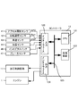
- the controller 12 is a control means for comprehensively controlling the engine 1 and the transmission 4, and as shown in FIG. 2, a CPU 121, a storage device 122 including a RAM / ROM, an input interface 123, an output interface 124, , And a bus 125 for interconnecting them.
- accelerator opening APO an accelerator pedal opening
- Npri the rotational speed of the transmission 4
- VSP traveling speed of the vehicle
- the storage device 122 stores a control program for the engine 1, a shift control program for the transmission 4, and a shift map used in the shift control program.
- the CPU 121 reads and executes a shift control program stored in the storage device 122, performs various arithmetic processes on various signals input via the input interface 123, and outputs a fuel injection signal, an ignition timing signal, a throttle An opening signal and a shift control signal are generated, and the generated shift control signal is output to the hydraulic control circuit 11 via the output interface 124.
- Various values used in the arithmetic processing by the CPU 121 and the arithmetic results are appropriately stored in the storage device 122.
- the hydraulic control circuit 11 includes a plurality of flow paths and a plurality of hydraulic control valves.
- the hydraulic control circuit 11 controls a plurality of hydraulic control valves on the basis of the shift control signal from the controller 12 to switch the hydraulic pressure supply path, and obtains the necessary hydraulic pressure from the hydraulic pressure generated by the mechanical oil pump 10m or the electric oil pump 10e. It is prepared and supplied to each part of the transmission 4. As a result, the gear ratio vRatio of the variator 20 and the gear position of the auxiliary transmission mechanism 30 are changed, and the transmission 4 is changed.
- the controller 12 stops the rotation of the engine 1 while the vehicle is running, in addition to the idle stop control that stops the rotation of the engine 1 while the vehicle is stopped. Perform coast stop control.
- Coast stop control is a control that suppresses fuel consumption by automatically stopping the engine 1 while the vehicle is traveling in a low vehicle speed range immediately before stopping.
- the coast stop control is common to the fuel cut control executed when the accelerator is off and the fuel supply to the engine 1 is stopped. However, the normal fuel cut control is executed at a relatively high speed and the engine brake is applied.
- the lock-up clutch of the torque converter 2 is engaged in order to ensure that the coast stop control is performed at a relatively low speed immediately before the vehicle stops, and the engine 1 is rotated with the lock-up clutch released. It is different in that it is stopped.
- the controller 12 first determines, for example, the following conditions (a) to (d).
- (A): The foot is released from the accelerator pedal (accelerator opening APO 0)
- These conditions are, in other words, conditions for judging that the driver intends to stop.
- the controller 12 stops the fuel supply to the engine 1 and stops the rotation of the engine 1.
- FIG. 3 is an explanatory diagram of a hydraulic circuit centered on the hydraulic control circuit 11 according to the embodiment of the present invention.
- the hydraulic control circuit 11 receives the hydraulic pressure supplied from the mechanical oil pump 10m or the electric oil pump 10e, adjusts the hydraulic pressure, and supplies the hydraulic pressure to the variator 20 and the auxiliary transmission mechanism 30, respectively.
- the hydraulic control circuit 11 includes a regulator valve 230, a secondary hydraulic control valve 220, and a shift control valve 210.
- the regulator valve 230 is a control valve that regulates the hydraulic pressure of the mechanical oil pump 10 m to a predetermined line pressure and supplies it to the oil passage 200.
- the secondary hydraulic control valve 220 is a control valve that regulates the secondary hydraulic pressure supplied to the hydraulic cylinder 23 b of the secondary pulley 22 using the line pressure as the original pressure.
- the shift control valve 210 is a control valve that regulates the primary hydraulic pressure supplied to the hydraulic cylinder 23a of the primary pulley 21 using the line pressure as the original pressure.
- the hydraulic control circuit 11 is connected to a mechanical oil pump 10m and an electric oil pump 10e, and is supplied with hydraulic pressure.
- the mechanical oil pump 10m is driven by the engine 1 to supply hydraulic pressure.
- the electric oil pump 10e is driven under the control of the controller 12 to supply hydraulic pressure when the hydraulic pressure cannot be supplied by the mechanical oil pump 10m, such as when the engine 1 is stopped.
- the hydraulic pressure output from the electric oil pump 10e is supplied to the oil passage 200 via the relief valve 211 and the check valve 212.
- the check valve 212 prevents reverse hydraulic pressure from being applied to the electric oil pump 10e when the mechanical oil pump 10m is driven.
- the relief valve 211 regulates the upper limit value of the hydraulic pressure supplied by the electric oil pump 10e as will be described later.
- the regulator valve 230 and the secondary hydraulic control valve 220 are provided with solenoids. By controlling the duty ratio of these solenoids according to a command from the controller 12, the hydraulic pressure by each valve is controlled.
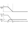
- FIG. 4 is an explanatory diagram of coast stop control according to the embodiment of the present invention.
- FIG 4 shows the engine rotational speed Ne, and the lower part shows the hydraulic pressure supplied by the mechanical oil pump 10m (shown by a dotted line) and the hydraulic pressure supplied by the electric oil pump 10e (shown by a solid line).
- the controller 12 stops the supply of fuel to the engine 1 and stops the rotation of the engine 1 (timing t01).
- the controller 12 starts driving the electric oil pump 10e when the engine 1 is in the coast stop state (timing t01). Thereby, even if the hydraulic pressure is not supplied from the mechanical oil pump 10m, the hydraulic pressure of the electric oil pump 10e can be supplied to the hydraulic control circuit 11.
- the hydraulic oil pressure that can be discharged by the electric oil pump 10e is smaller than that of the mechanical oil pump 10m. This is because the transmission 4 does not need to transmit torque when the engine 1 is stopped. This is because it is only necessary to secure the minimum hydraulic pressure necessary for fastening 30. By reducing the capacity of the electric oil pump 10e, the size and weight of the electric oil pump 10e can be reduced.
- the clamping force of the V-belt 23 by the variator 20 is reduced.
- a transmission torque capacity that is a capacity (power transmission capacity) capable of transmitting power (torque) in the variator 20.
- the V belt 23 may slip.
- the controller 12 In order to prevent the slip of the V belt 23, the controller 12 normally controls the transmission torque capacity of the variator 20 to be larger than the transmission torque capacity of the auxiliary transmission mechanism 30. However, in this case, since the hydraulic pressure is low, the resolution of the control is lowered and accurate control cannot be performed.
- the change in the output torque of the engine 1 can be detected by the accelerator pedal opening, the fuel injection amount calculated by the controller 12, and the like.
- the variator 20 and the auxiliary transmission mechanism 30 can be controlled to prevent the V belt from slipping by controlling the hydraulic pressure.
- the re-engagement after the auxiliary transmission mechanism 30 slips can be performed based on the change in the torque of the engine 1.
- the slipping of the V belt 23 of the variator 20 during the coast stop control is prevented by configuring as follows.
- FIG. 5 is an explanatory diagram showing a relationship between the hydraulic pressure and the transmission torque capacity in the variator 20 and the auxiliary transmission mechanism 30 according to the embodiment of the present invention.
- a solid line indicates a capacity (power transmission) in which power is transmitted by the V-belt 23 sandwiched by the variator 20 supplying hydraulic pressure to the hydraulic cylinders 23a and 23b provided in the primary pulley 21 and the secondary pulley 22, respectively.
- the relationship between the transmission torque capacity (capacity) and the hydraulic pressure is shown.
- the dotted line is transmitted when the frictional engagement element is engaged by supplying hydraulic pressure to any of the frictional engagement elements (Low brake 32, High clutch 33, Rev brake 34) that transmit power in the auxiliary transmission mechanism 30.
- the relationship between the torque capacity to be applied and the hydraulic pressure is shown.
- the variator 20 is provided with a second urging portion such as a spring that urges the V belt 23 in the clamping direction in order to prevent the V belt 23 from slipping even when the hydraulic pressure is lowered. Since the spring force (second urging force) of the second urging portion increases the clamping force of the V-belt 23, the variator 20 can exhibit a certain amount of transmission torque capacity S even when no hydraulic pressure is supplied. .
- a second urging portion such as a spring that urges the V belt 23 in the clamping direction in order to prevent the V belt 23 from slipping even when the hydraulic pressure is lowered. Since the spring force (second urging force) of the second urging portion increases the clamping force of the V-belt 23, the variator 20 can exhibit a certain amount of transmission torque capacity S even when no hydraulic pressure is supplied. .
- the frictional engagement element of the auxiliary transmission mechanism 30 is provided with a first urging portion such as a return spring that urges toward the release side to prevent dragging at the time of release.
- the spring force (first urging force) by the first urging portion acts to reduce the fastening force for frictional fastening. Therefore, in order for the frictional engagement element to have a transmission torque capacity, it is necessary to supply a hydraulic pressure larger than the hydraulic pressure P0 equivalent to the first biasing force of the first biasing portion.
- the facing of the frictional engagement element (friction material), the pulleys 21, 22 and the V-belt 23 have different transmission torque capacity characteristics with respect to an increase in hydraulic pressure.
- the frictional engagement element increases the frictional force due to the increase in hydraulic pressure and increases the transmission torque capacity.
- the pulleys 21 and 22 and the V-belt 23 are in contact with each other and the frictional force is not large, the transmission torque against the increase in hydraulic pressure.
- the increase in capacity is moderate compared to the frictional engagement element.
- the transmission torque capacity in the variator 20 may be set to a value smaller than the hydraulic pressure P2 shown in FIG. 5 so that the transmission torque capacity in the friction engagement element of the auxiliary transmission mechanism 30 is always larger.
- the relief valve 211 for controlling the upper limit value of the hydraulic pressure supplied by the electric oil pump 10e to the hydraulic pressure P2 is provided.
- the upper limit of the hydraulic pressure supplied to the oil passage by the relief valve 211 is limited to the hydraulic pressure P2. That is, even if the electric oil pump 10e can generate a hydraulic pressure larger than the hydraulic pressure P2, the portion exceeding the hydraulic pressure P2 is drained by the relief valve 211 and does not exceed the hydraulic pressure P2.
- P1 indicates the minimum hydraulic pressure that can be supplied by the electric oil pump 10e.
- the hydraulic pressure P1 is set to the lowest value at which the frictional engagement element of the auxiliary transmission mechanism 30 does not cause a slip.
- the hydraulic pressure is supplied to the variator 20 and the auxiliary transmission mechanism 30 by the electric oil pump 10e.
- the upper limit value of the hydraulic pressure at this time is limited by the relief valve 211, and the transmission torque capacity of the variator 20 is set to exceed the transmission torque capacity of the auxiliary transmission mechanism 30 as shown in the characteristic shown in FIG.
- the transmission torque capacity of the variator 20 exceeds the transmission torque capacity of the auxiliary transmission mechanism 30 in the entire hydraulic pressure region supplied by the electric oil pump 10e. Even when torque is input, the clutch fuse due to slipping of the frictional engagement element of the auxiliary transmission mechanism 30 is exhibited. Therefore, slippage of the V belt 23 of the variator 20 can be prevented even in a state where hydraulic pressure is supplied by the electric oil pump 10e, such as during coast stop control. If the characteristics of the electric oil pump 10e are set so that the upper limit of the hydraulic pressure supplied by the electric oil pump 10e is equal to the hydraulic pressure P2, the relief valve 211 need not be provided.
- FIG. 6 is an explanatory diagram of the primary pulley 21 of the variator 20 according to the embodiment of the present invention. Since the configuration of the secondary pulley 22 is the same, the description thereof is omitted.
- the upper stage shows the case where the movable pulley 120 retreats and the winding diameter of the V belt 23 is small
- the lower stage shows the case where the movable pulley 120 advances and the winding diameter of the V belt 23 is large.
- the primary pulley 21 is formed with a fixed pulley 110 at the end of the rotating shaft 100.
- a movable pulley 120 is slidably fitted on the outer periphery of the rotating shaft 100.
- the V belt 23 is sandwiched between the sheave surface 110 a of the fixed pulley 110 and the sheave surface 120 a of the movable pulley 120.
- the hydraulic pulley 130 is provided in the movable pulley.
- the movable pulley 120 moves forward and backward with respect to the fixed pulley 110, the interval between the sheave surface 110a and the sheave surface 120a is changed, and the winding diameter of the V belt is changed.
- shifting is performed.
- the hydraulic chamber 130 is provided with a return spring 140.
- the return spring 140 functions as a second urging unit that urges the movable pulley 120 in the traveling direction with respect to the fixed pulley 110 to increase the clamping force of the V belt 23 by the second urging force. Even when the hydraulic pressure in the hydraulic chamber 130 is lowered by the return spring 140, the movable pulley 120 is urged toward the fixed pulley 110, sandwiching the V belt 23, and torque is transmitted by the V belt 23.
- the variator 20 can exhibit the transmission torque capacity S by the return spring 140 even when no hydraulic pressure is supplied.
- FIG. 7 is an explanatory diagram of a frictional engagement element of the auxiliary transmission mechanism 30 according to the embodiment of the present invention.
- FIG. 7 illustrates the configuration of the high clutch 33, but the configurations of the low brake 32 and the rev brake 34 are the same, and thus the description thereof is omitted.
- the frictional engagement element transmits a driving force from the driving side to the driven side by the piston 320 movable by the hydraulic pressure supplied to the hydraulic chamber 310 sandwiching the driving friction plate 321 and the driven friction plate 322. Is done.
- the hydraulic chamber 310 is biased toward the release side in order to prevent dragging due to the contact between the drive-side friction plate 321 and the driven-side friction plate 322 at the time of release.
- a return spring 330 is provided as a first urging portion that reduces the torque transmission capacity of the first urging force with a first urging force.
- the relationship between the transmission torque capacity and the supply hydraulic pressure is determined by the return springs 140 and 330.
- the transmission torque capacity of the variator 20 can be set to exceed the transmission torque capacity of the auxiliary transmission mechanism 30.
- FIG. 8 is an explanatory diagram showing the relationship between the hydraulic pressure and the transmission torque capacity in the variator 20 and the auxiliary transmission mechanism 30 according to the embodiment of the present invention.
- the thick solid line and the thin solid line indicate the relationship between the transmission torque capacity and the hydraulic pressure in the variator 20
- the dotted line indicates the relationship between the transmission torque capacity of the frictional engagement element of the auxiliary transmission mechanism 30 and the hydraulic pressure.
- the spring characteristic of the return spring 140 of the variator 20 is changed so as to increase the spring force.
- the characteristic of the variator 20 is changed as shown by a thick solid line in FIG.
- the transmission torque capacity of the variator 20 exceeds the transmission torque capacity of the auxiliary transmission mechanism 30 in the range of the maximum value P2 and the minimum value P1 of the hydraulic pressure that can be supplied by the electric oil pump 10e.
- the spring characteristic of the return spring 140 is changed so that the transmission torque capacity of the variator 20 is equal to or greater than the transmission torque capacity of the frictional engagement element at the hydraulic pressure P2.
- FIG. 9 is an explanatory diagram showing the relationship between the hydraulic pressure and the transmission torque capacity in the variator 20 and the auxiliary transmission mechanism 30 according to the embodiment of the present invention.
- the thick solid line indicates the relationship between the transmission torque capacity and the hydraulic pressure in the variator 20
- the thick dotted line and the thin dotted line indicate the relationship between the transmission torque capacity of the frictional engagement element of the auxiliary transmission mechanism 30 and the hydraulic pressure.
- the maximum value and the minimum value of the hydraulic pressure that can be supplied by the electric oil pump 10e are P2 and P1.
- the transmission torque capacity of the frictional engagement element of the auxiliary transmission mechanism 30 has a characteristic indicated by a thin dotted line. In this case, the region where the transmission torque capacity of the variator 20 exceeds the transmission torque capacity of the auxiliary transmission mechanism 30 is small depending on the hydraulic pressure generated by the electric oil pump 10e.
- the spring characteristic of the return spring 330 of the subtransmission mechanism 30 is changed so that the spring force is increased.
- the characteristics of the auxiliary transmission mechanism 30 are changed as shown by the thick dotted lines in FIG.
- the transmission torque capacity of the variator 20 can exceed the transmission torque capacity of the auxiliary transmission mechanism 30 in the range of the maximum value P2 and the minimum value P1 of the hydraulic pressure that can be supplied by the electric oil pump 10e.
- the spring characteristic of the return spring 330 is changed so that the transmission torque capacity of the variator 20 is equal to or greater than the transmission torque capacity of the frictional engagement element at the hydraulic pressure P2.
- the transmission torque capacity of the variator 20 is also changed to the auxiliary transmission mechanism 30 by changing at least one of the spring force of the return spring 140 of the variator 20 and the spring force of the return spring 330 of the frictional engagement element of the auxiliary transmission mechanism 30. It can be set to exceed the transmission torque capacity.
- the transmission torque capacity of the variator 20 can be set to exceed the transmission torque capacity of the auxiliary transmission mechanism 30.
- the gear ratio can be changed by changing the winding diameter of the belt 23 mounted on the vehicle and clamped by the hydraulic pressure supplied to the pulleys (the primary pulley 21 and the secondary pulley).
- a continuously variable transmission mechanism (variator) 20 and a frictional engagement element (Low brake 32, High clutch 33, which is connected to the variator 20 and transmits the driving force of the engine 1 as a driving force source to the driving wheels 7 in an intermittent manner.
- Rev brake 34 The continuously variable transmission mechanism
- a controller 12 configured as a coast stop control unit that performs a coast stop that stops the driving force source in a running state of the vehicle, and a first that is driven by the driving force of the engine 1 and supplies hydraulic pressure to the variator 20 and the frictional engagement element.
- a mechanical oil pump 10m as a hydraulic pressure source and a second hydraulic pressure that is arranged in parallel with the mechanical oil pump 10m and can supply hydraulic pressure to the variator 20 and the frictional engagement element even when the driving force of the engine 1 is stopped.
- an electric oil pump 10e as a source.
- the sub-transmission mechanism 30 is obtained by hydraulic pressure from the first or second hydraulic power source, and controls a first transmission capacity that transmits and outputs the power of the engine 1 and controls the first transmission capacity to reduce the first transmission capacity.
- a return spring 330 is provided as a first urging portion having power, and the variator 20 is obtained by hydraulic pressure from the first or second hydraulic power source, and a second transmission capacity for transmitting and outputting the power of the engine 1 is controlled.
- a return spring 140 as a second urging portion having a second urging force for increasing the second transmission capacity.
- the second transmission capacity of the variator 20 is greater than or equal to the first transmission capacity of the auxiliary transmission mechanism 30 in the entire hydraulic pressure region supplied by the electric oil pump 10e. At least one of the first urging force and the second urging force is set so that
- the maximum value of the hydraulic pressure that can be supplied by the electric oil pump 10e is P2, and the entire hydraulic pressure area where the electric oil pump 10e is used is configured to be from the minimum value P1 to the maximum value P2.
- the transfer torque capacity of the variator 20 in the entire hydraulic pressure region of the electric oil pump 10e is the transfer torque capacity of the friction engagement element. Since it can be controlled to exceed, no matter what hydraulic pressure is supplied from the electric oil pump 10e, the V belt 23 does not slip.
- the present invention is not limited to this, and the entire hydraulic pressure range that uses the electric oil pump 10e is greater than the maximum value that can be supplied by the electric oil pump 10e.
- P2 may be set as a low oil pressure. That is, you may set so that it may become "P1 ⁇ P2 ⁇ maximum value which electric oil pump 10e can supply".
- the transmission torque capacity of the variator 20 can be controlled so as to exceed the transmission torque capacity of the frictional engagement element in the entire hydraulic pressure region of the electric oil pump 10e, and the V belt 23 is used in the usage region of the electric oil pump 10e. None slip.
- the second transmission capacity of the variator 20 can be set to be equal to or greater than the first transmission capacity of the auxiliary transmission mechanism 30.
- the lower limit value of the hydraulic pressure generated by the electric oil pump 10e as the second hydraulic power source is set to a hydraulic pressure at which the frictional engagement element of the auxiliary transmission mechanism 30 can be engaged, release of the frictional engagement element is suppressed. In addition, it is possible to improve the responsiveness and suppress the shock when re-acceleration is requested after the coast stop control.
- a relief valve 211 that restricts the upper limit value of the hydraulic pressure supplied by the electric oil pump 10e so that the second transmission capacity of the variator 20 and the first transmission capacity of the subtransmission mechanism 30 are equal to or less than the hydraulic pressure P2 that matches the hydraulic pressure.
- the upper limit of the hydraulic pressure supplied to the oil passage is limited to the hydraulic pressure P2. That is, even if the electric oil pump 10e can generate a hydraulic pressure larger than the hydraulic pressure P2, the portion exceeding the hydraulic pressure P2 is drained by the relief valve 211 and can be controlled so as not to exceed the hydraulic pressure P2. The slip of the V belt 23 can be prevented.
- the relief valve 211 drains the hydraulic pressure supplied to the electric oil pump 10 e when the first transmission capacity of the auxiliary transmission mechanism 30 is larger than the second transmission capacity of the variator 20.
- the hydraulic pressure can be supplied so that the first transmission capacity of the auxiliary transmission mechanism 30 is larger than the two transmission capacity.
- a belt type continuously variable transmission mechanism is provided as the variator 20, but the variator 20 is a continuously variable transmission mechanism in which a chain is wound around pulleys 21 and 22 instead of the belt 23. May be.
- the variator 20 may be a toroidal continuously variable transmission mechanism in which a tiltable power roller is disposed between the input disk and the output disk.
- the sub-transmission mechanism 30 is a transmission mechanism having two stages of first speed and second speed as the forward shift stage.
- the sub-transmission mechanism 30 is a forward shift stage and has three or more shift stages. A transmission mechanism having the same may be used.
- the auxiliary transmission mechanism 30 is configured using a Ravigneaux type planetary gear mechanism, but is not limited to such a configuration.
- the subtransmission mechanism 30 may be configured by combining a normal planetary gear mechanism and a frictional engagement element, or a plurality of power transmission paths configured by a plurality of gear trains having different gear ratios, and these powers You may comprise by the frictional engagement element which switches a transmission path.
- the auxiliary transmission mechanism 30 may be in the front stage or the rear stage.
- the auxiliary transmission mechanism 30 is provided in the rear stage of the engine 1 and in the front stage of the variator 20, it is particularly effective for the impact torque from the engine 1.
- the auxiliary transmission mechanism 30 is provided in the subsequent stage of the variator 20, it is particularly effective for the impact torque from the drive wheels 7.
- the sub-transmission mechanism 30 instead of the sub-transmission mechanism 30 having a gear position, only a forward / reverse switching mechanism or a clutch mechanism that performs only power interruption may be used.
Landscapes
- Engineering & Computer Science (AREA)
- General Engineering & Computer Science (AREA)
- Mechanical Engineering (AREA)
- Control Of Transmission Device (AREA)
- Control Of Vehicle Engines Or Engines For Specific Uses (AREA)
- Transmissions By Endless Flexible Members (AREA)
Abstract
第1付勢力及び第2付勢力の少なくとも一方は、車両の走行状態において駆動力源を停止するコーストストップ状態において、駆動力源の駆動力が停止し前記第2油圧源が油圧を供給する場合に、第2油圧源が供給する全油圧領域において、無段変速機構の第2伝達容量が摩擦締結要素の第1伝達容量以上となるように設定される。
Description
本発明は、駆動力源の停止、再始動を行う車両に搭載される無段変速機の制御装置に関する。
ベルト式無段変速機は、エンジンにより駆動されるメカニカルオイルポンプで発生する油圧が供給される。プライマリプーリ及びセカンダリプーリには、この油圧を元圧とするプーリ圧(プライマリプーリ圧及びセカンダリプーリ圧)が供給される。これらプーリ圧によってベルトを挟持すると共に、これらプーリ圧を制御することで各プーリの溝幅が変更されて、変速が行われる。
このベルト式無段変速機に、動力を伝達するクラッチが直列に接続されている場合は、トルクの入力によりベルトがスリップすることを防止するために、ベルトの締結力よりもクラッチの締結力を低下させる、いわゆるクラッチフューズ制御が行われている。
このようなクラッチフューズ制御として、JP1998-002390Aには、クラッチのスリップが検出されたときにはクラッチ締結力及びベルト押圧力をそれぞれ増大制御すると共に、スリップが検出されないときにはクラッチ締結力及びベルト押圧力をそれぞれ減少制御するものが知られている。
近年、燃料性能の向上を目的として、車両停車時だけでなく、車両が停車する前にエンジンを停止する、いわゆるコーストストップ制御が行われている。コーストストップ制御中においても、急ブレーキや段差乗り上げ等により駆動輪からトルクが入力されると、ベルトスリップが生じる可能性があるため、コーストストップ制御中であってもクラッチフューズ制御を行うことが望ましい。
コーストストップ制御では、エンジンの停止に伴ってエンジンにより駆動されるメカニカルオイルポンプが油圧を発生できなくなる。従って、メカニカルオイルポンプに代わって油圧を供給する電動オイルポンプを備え、コーストストップ制御中、電動オイルポンプが発生する油圧に基づきクラッチフューズ制御を行うことが考えられる。
しかしながら、油圧制御により得られる実油圧は、ばらつきにより必ずしも指示油圧に一致した油圧とはならない。このような場合、ベルトの締結力よりもクラッチの締結力が大きくなり、駆動輪から入力されるトルクによりベルトがスリップしてしまう。例えば、ベルトの締結力を制御する指示油圧に対して低い実油圧が得られた場合や、クラッチの締結力を制御する指示油圧に対して高い実油圧が得られた場合、ベルトの締結力よりもクラッチの締結力が大きくなる可能性がある。
上記ばらつきにより、ベルトの締結力よりもクラッチの締結力が大きくなることを防止するために、クラッチの指示油圧をクラッチフューズ機能が達成される油圧よりさらに低下させることが考えられる。しかしながら、コーストストップ制御中は、メカニカルオイルポンプに比べて吐出圧の低い電動オイルポンプを油圧源としているため、クラッチへの指示油圧を低下させすぎると、駆動輪から過剰なトルクが入力されていないにも関わらずクラッチがスリップする可能性がある。クラッチがスリップすると、クラッチの発熱に伴う耐久性の低下や、再加速要求時のクラッチ締結ラグに伴う再加速性の低下といった問題が発生する。
本発明はこのような問題点に鑑みてなされたものであり、コーストストップ制御によりエンジン停止状態においても、ベルトのスリップを防止することができる無段変速機の制御装置を提供することを目的とする。
本発明の一実施態様によると、車両に搭載され、プーリに供給される油圧により挟持される動力伝達ベルトの巻掛け径を変更して変速比を変更可能な無段変速機構と、無段変速機構に接続され、駆動力源の駆動力を駆動輪へと断続可能に伝達する摩擦締結要素と、車両の走行状態において駆動力源を停止するコーストストップ制御部と、駆動力源により駆動され無段変速機構及び摩擦締結要素へ油圧を供給する第1油圧源と、第1油圧源と並列に配設され、無段変速機構及び摩擦締結要素へ油圧を供給可能な第2油圧源と、摩擦締結要素に配され、第1又は第2油圧源からの油圧により得られる第1伝達容量を低減させる方向に働く第1付勢力を有する第1付勢部と、無段変速機構に配され、第1又は第2油圧源からの油圧により得られる第2伝達容量を増大させる方向に働く第2付勢力を有する第2付勢部と、を備え、第1付勢力及び第2付勢力の少なくとも一方は、駆動力源の駆動力が停止し第2油圧源が油圧を供給する場合に、第2油圧源が供給する全油圧領域において第2伝達容量が第1伝達容量以上となるように設定されることを特徴とする。
本発明の別の実施態様によると、車両に搭載され、プーリに供給される油圧により挟持される動力伝達ベルトの巻掛け径を変更して変速比を変更可能な無段変速機構と、無段変速機構に接続され、駆動力源の駆動力を駆動輪へと断続可能に伝達する摩擦締結要素と、駆動力源により駆動され無段変速機構及び摩擦締結要素へ油圧を供給する第1油圧源と、第1油圧源と並列に配設され、無段変速機構及び摩擦締結要素へ油圧を供給可能な第2油圧源と、を備え、車両の走行状態において駆動力源を停止するコーストストップ制御と、コーストストップ制御の実行中に第2油圧源を駆動する制御と、を実行する無段変速機の制御装置において、第2油圧源の吐出油路上に備えられ、第2油圧源から供給される油圧を、無段変速機構の動力伝達容量と摩擦締結要素の動力伝達容量とが一致する油圧以下に規制する規制部を備えることを特徴とする。
上記態様によると、コーストストップにより駆動力源が停止し、第1油圧源に代えて第2油圧源が供給する油圧により無段変速機構及び副変速機構の伝達容量を制御する場合に、第2油圧源が供給する全油圧領域において、無段変速機構の第2伝達容量が副変速機構の第1伝達容量以上となるように設定される。このような構成によって、コーストストップにより駆動力源が停止して油圧が低下する場合であっても、無段変速機構の第2伝達容量が副変速機構の第1伝達容量以上となるので、無段変速機構の動力伝達ベルトがスリップすることが防止される。
以下、添付図面を参照しながら本発明の実施形態について説明する。
図1は本発明の実施形態に係る無段変速機を搭載した車両の概略構成図である。この車両は動力源としてエンジン1を備える。エンジン1の出力回転は、ロックアップクラッチ付きトルクコンバータ2、第1ギヤ列3、無段変速機(以下、単に「変速機4」という。)、第2ギヤ列5、終減速装置6を介して駆動輪7へと伝達される。第2ギヤ列5には駐車時に変速機4の出力軸を機械的に回転不能にロックするパーキング機構8が設けられている。
また、車両には、エンジン1の回転が入力され、エンジン1の動力の一部を利用して駆動されるメカオイルポンプ10mと、バッテリ13から電力供給を受けて駆動される電動オイルポンプ10eとが設けられている。また、変速機4には、メカオイルポンプ10m及び電動オイルポンプ10eの少なくとも一方から供給される油圧を調圧して変速機4の各部に供給する油圧制御回路11と、油圧制御回路11及びエンジン1を制御するコントローラ12とが設けられている。
変速機4は、無段変速機構(以下、「バリエータ20」という。)と、バリエータ20に対して直列に設けられる副変速機構30とを備える。「直列に設けられる」とは同動力伝達経路においてバリエータ20と副変速機構30が直列に設けられるという意味である。副変速機構30は、この例のようにバリエータ20の出力軸に直接接続されていてもよいし、その他の変速ないし動力伝達機構(例えば、ギヤ列)を介して接続されていてもよい。
バリエータ20は、プライマリプーリ21と、セカンダリプーリ22と、プーリ21、22の間に掛け回されるベルト(Vベルト)23とを備えるベルト式無段変速機構である。プーリ21、22は、それぞれ固定円錐板と、この固定円錐板に対してシーブ面を対向させた状態で配置され固定円錐板との間にV溝を形成する可動円錐板と、この可動円錐板の背面に設けられて可動円錐板を軸方向に変位させる油圧シリンダ23a、23bとを備える。油圧シリンダ23a、23bに供給される油圧を調整すると、V溝の幅が変化してベルト23と各プーリ21、22との接触半径が変化し、バリエータ20の変速比vRatioが無段階に変化する。
副変速機構30は前進2段・後進1段の変速機構である。副変速機構30は、2つの遊星歯車のキャリアを連結したラビニョウ型遊星歯車機構31と、ラビニョウ型遊星歯車機構31を構成する複数の回転要素に接続され、それらの連係状態を変更する複数の摩擦締結要素(Lowブレーキ32、Highクラッチ33、Revブレーキ34)とを備える。各摩擦締結要素32~34への供給油圧を調整し、各摩擦締結要素32~34の締結・解放状態を変更すると、副変速機構30の変速段が変更される。
例えば、Lowブレーキ32を締結し、Highクラッチ33とRevブレーキ34を解放すれば副変速機構30の変速段は1速となる。Highクラッチ33を締結し、Lowブレーキ32とRevブレーキ34を解放すれば副変速機構30の変速段は1速よりも変速比が小さな2速となる。また、Revブレーキ34を締結し、Lowブレーキ32とHighクラッチ33を解放すれば副変速機構30の変速段は後進となる。以下の説明では、副変速機構30の変速段が1速であるとき「変速機4が低速モードである」と表現し、2速であるとき「変速機4が高速モードである」と表現する。
コントローラ12は、エンジン1及び変速機4を統括的に制御する制御手段であり、図2に示すように、CPU121と、RAM・ROMからなる記憶装置122と、入力インターフェース123と、出力インターフェース124と、これらを相互に接続するバス125とから構成される。
入力インターフェース123には、アクセルペダルの開度(以下、「アクセル開度APO」という。)を検出するアクセル開度センサ41の出力信号、変速機4の入力回転速度(=プライマリプーリ21の回転速度、以下、「プライマリ回転速度Npri」という。)を検出する回転速度センサ42の出力信号、車両の走行速度(以下、「車速VSP」という。)を検出する車速センサ43の出力信号、変速機4の油温を検出する油温センサ44の出力信号、セレクトレバー45の位置を検出するインヒビタスイッチ46の出力信号、ブレーキペダルの踏み込み量及びブレーキの液圧を検出するブレーキセンサ47の出力信号などが入力される。
記憶装置122には、エンジン1の制御プログラム、変速機4の変速制御プログラム、この変速制御プログラムで用いる変速マップが格納されている。CPU121は、記憶装置122に格納されている変速制御プログラムを読み出して実行し、入力インターフェース123を介して入力される各種信号に対して各種演算処理を施して、燃料噴射信号、点火時期信号、スロットル開度信号、変速制御信号を生成し、生成した変速制御信号を出力インターフェース124を介して油圧制御回路11に出力する。CPU121が演算処理で使用する各種値、その演算結果は記憶装置122に適宜格納される。
油圧制御回路11は複数の流路、複数の油圧制御弁で構成される。油圧制御回路11は、コントローラ12からの変速制御信号に基づき、複数の油圧制御弁を制御して油圧の供給経路を切り換え、メカオイルポンプ10m又は電動オイルポンプ10eが発生した油圧から必要な油圧を調製し、これを変速機4の各部位に供給する。これにより、バリエータ20の変速比vRatio、副変速機構30の変速段が変更され、変速機4の変速が行われる。
本実施形態のコントローラ12は、燃料消費量を抑制するために、車両が停止している間にエンジン1の回転を停止するアイドルストップ制御に加え、車両が走行中にもエンジン1の回転を停止させるコーストストップ制御を行う。
コーストストップ制御では、車両が停止直前の低車速域で走行している間、エンジン1を自動的に停止させて燃料消費量を抑制する制御である。コーストストップ制御は、アクセルオフ時に実行される燃料カット制御とエンジン1への燃料供給を停止する点で共通するが、通常の燃料カット制御は、比較的高速走行時において実行され、かつエンジンブレーキを確保するためにトルクコンバータ2のロックアップクラッチが係合されているのに対し、コーストストップ制御は、車両停止直前の比較的低速走行時に実行され、ロックアップクラッチを解放状態としてエンジン1の回転を停止させる点において相違する。
コーストストップ制御を実行するにあたって、コントローラ12は、まず、例えば以下に示す条件(a)~(d)を判断する。
(a):アクセルペダルから足が離されている(アクセル開度APO=0)
(b):ブレーキペダルが踏み込まれている(ブレーキセンサ47がON)
(c):車速が所定の低車速(例えば、15km/h)以下
(d):ロックアップクラッチが解放されている
(a):アクセルペダルから足が離されている(アクセル開度APO=0)
(b):ブレーキペダルが踏み込まれている(ブレーキセンサ47がON)
(c):車速が所定の低車速(例えば、15km/h)以下
(d):ロックアップクラッチが解放されている
これらの条件は、言い換えると運転者に停車意図があることを判断する条件である。
コントローラ12は、コーストストップ条件が成立した場合に、エンジン1への燃料の供給を停止して、エンジン1の回転を停止させる。
図3は、本発明の実施形態の油圧制御回路11を中心とした油圧回路の説明図である。
油圧制御回路11は、メカオイルポンプ10m又は電動オイルポンプ10eからの油圧の供給を受けて、この油圧を調圧して、バリエータ20及び副変速機構30それぞれに油圧を供給する。
油圧制御回路11には、レギュレータ弁230、セカンダリ油圧制御弁220、変速制御弁210が備えられている。
レギュレータ弁230は、メカオイルポンプ10mの油圧を所定のライン圧に調圧して油路200に供給する制御弁である。セカンダリ油圧制御弁220は、ライン圧を元圧として、セカンダリプーリ22の油圧シリンダ23bに供給するセカンダリ油圧を調圧する制御弁である。
変速制御弁210は、ライン圧を元圧として、プライマリプーリ21の油圧シリンダ23aに供給するプライマリ油圧を調圧する制御弁である。
油圧制御回路11には、メカオイルポンプ10m及び電動オイルポンプ10eが接続され、これらにより油圧が供給される。メカオイルポンプ10mは、エンジン1によって駆動されて油圧を供給する。電動オイルポンプ10eは、エンジン1が停止している場合など、メカオイルポンプ10mによって油圧が供給できない場合にコントローラ12の制御によって駆動され、油圧を供給する。
電動オイルポンプ10eが出力する油圧は、リリーフバルブ211及び逆止弁212を介して、油路200に供給される。逆止弁212は、メカオイルポンプ10mが駆動している場合に、電動オイルポンプ10eに逆の油圧がかかることを防止する。
リリーフバルブ211は、後述するように電動オイルポンプ10eが供給する油圧の上限値を規制する。
レギュレータ弁230及びセカンダリ油圧制御弁220にはソレノイドが備えられている。コントローラ12からの指令によってこれらソレノイドのデューティー比を制御することにより、各弁による油圧が制御される。
次に、このように構成された車両のコーストストップ制御を説明する。
図4は、本発明の実施形態のコーストストップ制御時の説明図である。
図4の上段はエンジン回転速度Neを示し、下段はメカオイルポンプ10mが供給する油圧(点線で示す)及び電動オイルポンプ10eが供給する油圧(実線で示す)、をそれぞれ示す。
前述のように、コントローラ12は、コーストストップ条件が成立した場合に、エンジン1への燃料の供給を停止して、エンジン1の回転を停止させる(タイミングt01)。
コーストストップ制御により、エンジン1の回転速度が徐々に低下する。これに伴って、エンジン1の駆動力によって油圧を発生させるメカオイルポンプ10mも漸次停止し、メカオイルポンプ10mからの油圧が油圧制御回路11に供給されなくなる(タイミングt02)。
エンジン1の停止中もバリエータ20の各プーリによるベルトの挟持力及び副変速機構30の摩擦締結要素の締結に油圧が必要となる。そこで、コントローラ12は、エンジン1をコーストストップ状態としたときに(タイミングt01)、電動オイルポンプ10eの駆動を開始する。これにより、メカオイルポンプ10mから油圧が供給されない状態となっても、電動オイルポンプ10eの油圧を油圧制御回路11に供給することができる。
電動オイルポンプ10eが吐出可能な油圧は、メカオイルポンプ10mよりも小さい、これは、エンジン1が停止している状態では変速機4がトルクを伝達する必要がないため、バリエータ20又は副変速機構30の締結に必要な最低限度の油圧を確保できればよいためである。電動オイルポンプ10eの容量を小さくすることにより、電動オイルポンプ10eのサイズ、重量を小型化することができる。
このように、コーストストップ状態では供給される油圧が小さくなるため、バリエータ20でのVベルト23の挟持力が低下する。特に、例えば、急ブレーキや段差の乗り上げ等により駆動輪7からトルクが入力され、このトルクがバリエータ20における動力(トルク)を伝達可能な容量(動力伝達容量)である伝達トルク容量を上回った場合には、Vベルト23のスリップが発生する虞がある。
具体的には、コーストストップ制御によりエンジン1が停止した場合は、メカオイルポンプ10mが駆動できないため、電動オイルポンプ10eのみから供給される油圧となり、バリエータ20及び副変速機構30における伝達トルク容量が低下してしまう。そのため、Vベルト23のスリップを防止するためにバリエータ20の油圧を高めることができない。
Vベルト23のスリップを防止するために、通常、コントローラ12は、バリエータ20の伝達トルク容量を副変速機構30の伝達トルク容量よりも大きくなるように制御する。しかしながら、この場合、油圧が低いため制御の分解能が低くなり正確な制御ができなくなる。
特に、トルクが入力されて副変速機構30の摩擦締結要素がスリップした場合は再締結を行うが、油圧が低いために再締結に時間がかったり、再締結できない場合が生ずる。このとき、再加速要求がされた場合には、エンジン1の再始動に伴いメカオイルポンプ10mから油圧が供給され、スリップ状態の摩擦締結要素を再締結することによるショックが発生する。
エンジン1が駆動している場合は、エンジン1の出力トルクの変化は、アクセルペダル開度やコントローラ12で算出される燃料噴射量等により検出可能である。これによりバリエータ20及び副変速機構30の油圧を制御してVベルトのスリップを防止する制御を行うことができる。特に副変速機構30がスリップした後の再締結を、エンジン1のトルクの変化に基づいて行うことができる。
一方で、コーストストップ制御時にはエンジン1が停止し駆動輪7側からトルクが入力されるが、トルクの入力が予測できず、車速も低いために入力トルクが小さく、副変速機構30のスリップの検知、再締結のための制御が行いにくくなる。そのため、再加速要求がされた場合には、摩擦締結要素を再締結することによるショックが発生する虞がある。
従って、コーストストップ制御において、Vベルト23のスリップを防止するために副変速機構30の摩擦締結要素をスリップさせる、いわゆるクラッチフューズを行うことが従来難しかった。
これに対して、本発明の実施形態では、次のように構成することにより、コーストストップ制御のときのバリエータ20のVベルト23のスリップを防止するようにした。
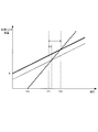
図5は、本発明の実施形態のバリエータ20及び副変速機構30における油圧と伝達トルク容量との関係を示す説明図である。
図5において、実線は、バリエータ20が、プライマリプーリ21及びセカンダリプーリ22それぞれに備えられる油圧シリンダ23a、23bに油圧を供給することにより挟持されるVベルト23により動力が伝達される容量(動力伝達容量)である伝達トルク容量と油圧との関係を示す。
点線は、副変速機構30において、動力を伝達する摩擦締結要素(Lowブレーキ32、Highクラッチ33、Revブレーキ34)のいずれかに油圧を供給することでこの摩擦締結要素が締結されることにより伝達されるトルク容量と油圧との関係を示す。
バリエータ20には、油圧が低下したときにもVベルト23のスリップを防止するため、Vベルト23を挟持方向に付勢するスプリング等の第2付勢部が備えられている。この第2付勢部のバネ力(第2付勢力)がVベルト23の挟持力を増大するので、バリエータ20は油圧が供給されない場合においても、ある程度の伝達トルク容量Sを発揮することができる。
一方、副変速機構30の摩擦締結要素には、解放時の引きずりを防止するため解放側に付勢するリターンスプリング等の第1付勢部が備えられている。この第1付勢部によるバネ力(第1付勢力)は摩擦締結用の締結力を低減するように作用する。従って、摩擦締結要素が伝達トルク容量を持つためには、第1付勢部の第1付勢力と均等な油圧P0よりも大きな油圧を供給する必要がある。
摩擦締結要素のフェーシング(摩擦材)と、プーリ21、22及びVベルト23とは、それぞれ油圧の上昇に対する伝達トルク容量の特性が異なる。摩擦締結要素は油圧の上昇により摩擦力が増大して伝達トルク容量が上昇するが、プーリ21、22及びVベルト23は金属同士の接触であり摩擦力は大きくないため、油圧の上昇に対する伝達トルク容量の上昇は、摩擦締結要素と比較して緩やかとなる。
このように、バリエータ20及び副変速機構30が、油圧に対して図5に示す特性を有するため、Vベルト23のスリップを防止するためには、バリエータ20及び副変速機構30に供給する油圧を、バリエータ20における伝達トルク容量が常に副変速機構30の摩擦締結要素における伝達トルク容量より大きくなるよう、図5に示す油圧P2よりも小さい値とすればよい。
そこで、本発明の実施形態では、電動オイルポンプ10eが供給する油圧の上限値を、油圧P2に制御するリリーフバルブ211を備えた。電動オイルポンプ10eが駆動しているときに、リリーフバルブ211により油路に供給される油圧の上限が油圧P2に制限される。すなわち、電動オイルポンプ10eが油圧P2より大きな油圧を発生可能であっても、油圧P2を超える分はリリーフバルブ211によりドレーンされ、油圧P2以上とはならない。なお、図5において、P1は電動オイルポンプ10eが供給可能な油圧の最低値を示す。この油圧P1は、副変速機構30の摩擦締結要素がスリップを発生しない最低の値に設定されている。
このように、コーストストップ制御時にメカオイルポンプ10mが停止した場合に、電動オイルポンプ10eにより油圧がバリエータ20及び副変速機構30に供給される。このときの油圧の上限値をリリーフバルブ211により制限して、図5に示す特性のように、バリエータ20の伝達トルク容量が副変速機構30の伝達トルク容量を上回るように設定する。
これにより、コーストストップ制御時にメカオイルポンプ10mが停止した場合にも、電動オイルポンプ10eにより供給される油圧の全油圧領域においてバリエータ20の伝達トルク容量が副変速機構30の伝達トルク容量を上回るので、トルクが入力された場合にも副変速機構30の摩擦締結要素がスリップすることによるクラッチフューズが発揮される。従って、コーストストップ制御時など、電動オイルポンプ10eにより油圧を供給する状態でも、バリエータ20のVベルト23のスリップを防止することができる。なお、電動オイルポンプ10eにより供給される油圧の上限が油圧P2となるように電動オイルポンプ10eの特性を設定すれば、リリーフバルブ211を設ける必要はない。
次に、バリエータ20及び副変速機構30の構成を説明する。
図6は、本発明の実施形態のバリエータ20のプライマリプーリ21の説明図である。なお、セカンダリプーリ22の構成も同様であるため、説明を省略する。
なお、図6において、上段は可動プーリ120が退行してVベルト23の巻掛け径が小さい場合を、下段は可動プーリ120が進行してVベルト23の巻掛け径が大きい場合を、それぞれ示す。
プライマリプーリ21は、回転軸100の端部に固定プーリ110が形成され。回転軸100の外周に可動プーリ120が摺動可能に嵌装されている。固定プーリ110のシーブ面110aと可動プーリ120のシーブ面120aとの間にVベルト23が挟持される。
可動プーリには油圧室130が備えられている。油圧室130の油圧を制御することにより、可動プーリ120が固定プーリ110に対して進退し、シーブ面110aとシーブ面120aとの間隔が変更されて、Vベルトの巻掛け径が変更される。プライマリプーリ21とセカンダリプーリ22とでVベルト23の巻掛け径を互いに変更することにより、変速が行われる。
油圧室130には、リターンスプリング140が備えられている。リターンスプリング140は、可動プーリ120を固定プーリ110に対して進行方向に付勢することにより、Vベルト23の挟持力を第2付勢力で増大する第2付勢部として機能する。リターンスプリング140によって、油圧室130の油圧が低下した場合にも、可動プーリ120が固定プーリ110側に付勢されて、Vベルト23を挟持し、Vベルト23によりトルクが伝達される。
このような構成により、図5に示すように、バリエータ20は油圧が供給されない場合においても、リターンスプリング140によって伝達トルク容量Sを発揮することができる。
図7は、本発明の実施形態の副変速機構30の摩擦締結要素の説明図である。
図7は、Highクラッチ33の構成を説明するが、Lowブレーキ32、Revブレーキ34の構成も同様であるため、説明を省略する。
摩擦締結要素は、油圧室310に供給される油圧により可動するピストン320が駆動側の摩擦板321と従動側の摩擦板322とを挟持することにより、駆動側から従動側へと駆動力が伝達される。
油圧室310には、解放時に駆動側の摩擦板321と従動側の摩擦板322とが接触することで引きずりが発生することを防止するために、解放側に付勢することにより、摩擦締結要素のトルク伝達容量を第1付勢力で減少する第1付勢部としてのリターンスプリング330が備えられている。
このような構成により、図5に示すように、摩擦締結要素に油圧が締結されない場合は伝達トルク容量を持たず、摩擦締結要素が伝達トルク容量を持つためには、第1付勢部の第1付勢力に抗して油圧P0を供給する必要がある。
このように、バリエータ20及び副変速機構30は、伝達トルク容量と供給油圧との関係が、リターンスプリング140、330によって決まる。
そこで、このリターンスプリング140、330の特性を変更することによっても、バリエータ20の伝達トルク容量が副変速機構30の伝達トルク容量を上回るように設定することができる。
図8は、本発明の実施形態のバリエータ20及び副変速機構30における油圧と伝達トルク容量との関係の示す説明図である。
図8において、太実線及び細実線は、バリエータ20における伝達トルク容量と油圧との関係を示し、点線は、副変速機構30の摩擦締結要素の伝達トルク容量と油圧との関係を示す。
図8において、電動オイルポンプ10eが供給可能な油圧の最大値及び最小値がP2及びP1であるとする。ここで、バリエータ20の伝達トルク容量が細実線で示す特性であったとする。この場合は、電動オイルポンプ10eが発生する油圧によっては、バリエータ20の伝達トルク容量が副変速機構30の伝達トルク容量を上回る領域が小さい。
そこで、バリエータ20のリターンスプリング140のバネ特性を、バネ力が大きくなるように変更する。リターンスプリング140のバネ特性を変更することにより、バリエータ20の特性が図8に示す太実線のように変更される。これにより電動オイルポンプ10eが供給可能な油圧の最大値P2及び最小値P1の範囲で、バリエータ20の伝達トルク容量が、副変速機構30の伝達トルク容量を上回る。具体的には、油圧P2においてバリエータ20の伝達トルク容量が摩擦締結要素の伝達トルク容量以上となるよう、リターンスプリング140のバネ特性を変更する。なお、リターンスプリング140のバネ特性を過剰に大きくすると、部品間における摩擦力が過剰となり抵抗の増大に伴う燃費悪化や部品間における摩耗が生じるため、油圧P2において、バリエータ20の伝達トルク容量と摩擦締結要素の伝達トルク容量とが一致するように設定することが望ましい。
図9は、本発明の実施形態のバリエータ20及び副変速機構30における油圧と伝達トルク容量との関係の示す説明図である。
図9において、太実線は、バリエータ20における伝達トルク容量と油圧との関係を示し、太点線及び細点線は、副変速機構30の摩擦締結要素の伝達トルク容量と油圧との関係を示す。
図8と同様に、図9においても、電動オイルポンプ10eが供給可能な油圧の最大値及び最小値がP2及びP1であるとする。ここで、副変速機構30の摩擦締結要素の伝達トルク容量が細点線で示す特性であったとする。この場合は、電動オイルポンプ10eが発生する油圧によっては、バリエータ20の伝達トルク容量が副変速機構30の伝達トルク容量を上回る領域が小さい。
そこで、副変速機構30のリターンスプリング330のバネ特性を、バネ力が大きくなるように変更する。リターンスプリング330のバネ特性を変更することにより、副変速機構30の特性が図9に示す太点線のように変更される。これにより電動オイルポンプ10eが供給可能な油圧の最大値P2及び最小値P1の範囲で、バリエータ20の伝達トルク容量が、副変速機構30の伝達トルク容量を上回ることができる。具体的には、油圧P2においてバリエータ20の伝達トルク容量が摩擦締結要素の伝達トルク容量以上となるよう、リターンスプリング330のバネ特性を変更する。なお、リターンスプリング330のバネ特性を過剰に大きくすると、解放状態の摩擦締結要素を締結するに際して、締結開始までに必要な油圧が高くなり、締結開始までに時間を要する点や、摩擦締結要素の締結状態を維持するために必要な油圧が高くなる点から、応答性の低下や燃費悪化となる。従って、油圧P2において、バリエータ20の伝達トルク容量と摩擦締結要素の伝達トルク容量とが一致するように設定することが望ましい。
このように、バリエータ20のリターンスプリング140のバネ力及び副変速機構30の摩擦締結要素のリターンスプリング330のバネ力の少なくとも一方を変更することによっても、バリエータ20の伝達トルク容量が副変速機構30の伝達トルク容量を上回るように設定することができる。
バリエータ20のリターンスプリング140のバネ力の変更、副変速機構30の摩擦締結要素のリターンスプリング330のバネ力の変更、及び、電動オイルポンプ10eの出力を規制するリリーフバルブ211の上限圧のうちの少なくとも一つを変更することにより、バリエータ20の伝達トルク容量が副変速機構30の伝達トルク容量を上回るように設定することができる。
以上のように、本発明の実施形態は、車両に搭載され、プーリ(プライマリプーリ21及びセカンダリプーリ)に供給される油圧により挟持されるベルト23の巻掛け径を変更して変速比を変更可能な無段変速機構(バリエータ)20と、バリエータ20に接続され、駆動力源としてのエンジン1の駆動力を駆動輪7へと断続可能に伝達する摩擦締結要素(Lowブレーキ32、Highクラッチ33、Revブレーキ34)、とを備える変速機4に適用される。
車両の走行状態において前記駆動力源を停止するコーストストップを行うコーストストップ制御部として構成されるコントローラ12と、エンジン1の駆動力により駆動されバリエータ20及び摩擦締結要素へと油圧を供給する第1油圧源としてのメカオイルポンプ10mと、メカオイルポンプ10mと並列に配設され、エンジン1の駆動力が停止しているときにもバリエータ20及び摩擦締結要素へと油圧を供給可能な第2油圧源としての電動オイルポンプ10eとを備える。
副変速機構30は、第1又は第2油圧源からの油圧により得られ、エンジン1の動力を伝達して出力する第1伝達容量が制御されると共に、第1伝達容量を低減させる第1付勢力を有する第1付勢部としてのリターンスプリング330を備え、バリエータ20は、第1又は第2油圧源からの油圧により得られ、エンジン1の動力を伝達して出力する第2伝達容量が制御されると共に、第2伝達容量を増大させる第2付勢力を有する第2付勢部としてのリターンスプリング140を備える。エンジン1の駆動力が停止し電動オイルポンプ10eが油圧を供給する場合に、電動オイルポンプ10eが供給する全油圧領域において、バリエータ20の第2伝達容量が副変速機構30の第1伝達容量以上となるように、第1付勢力及び第2付勢力の少なくとも一方を設定する。
このように構成することにより、コーストストップにより駆動力源が停止し、メカオイルポンプ10mに代えて電動オイルポンプ10eが供給する油圧によりバリエータ20及び副変速機構30の伝達容量を制御する場合に、電動オイルポンプ10eが供給する全油圧領域(最小値P1から最大値P2)において、リターンスプリング140により締結側に付勢されるバリエータ20の第2伝達容量が、リターンスプリング330により解放側に付勢される摩擦締結要素を備える副変速機構30の第1伝達容量以上となるので、トルクが入力された場合にも副変速機構30の摩擦締結要素がスリップすることによるクラッチフューズが発揮されて、バリエータ20のVベルト23のスリップを防止することができる。
電動オイルポンプ10eが供給可能な油圧の最大値をP2とし、電動オイルポンプ10eを使用する全油圧領域を最小値P1から最大値P2となるように構成する。これにより、電動オイルポンプ10eの供給油圧を最小値P1から最大値P2までの領域で使用する場合、電動オイルポンプ10eにおける全油圧領域においてバリエータ20の伝達トルク容量が摩擦締結要素の伝達トルク容量を上回るように制御することができるので、電動オイルポンプ10eからどのような油圧を供給してもVベルト23がスリップすることはない。
または、電動オイルポンプ10eの供給可能な油圧の最大値はP2としたが、これに限られることはなく、電動オイルポンプ10eを使用する全油圧領域を電動オイルポンプ10eが供給可能な最大値より低い油圧としてP2を設定してもよい。すなわち、「P1<P2<電動オイルポンプ10eが供給可能な最大値」となるように設定してもよい。この場合も上記同様、電動オイルポンプ10eにおける全油圧領域においてバリエータ20の伝達トルク容量が摩擦締結要素の伝達トルク容量を上回るように制御することができ、電動オイルポンプ10eの使用領域においてVベルト23がスリップすることはない。
リターンスプリング330の付勢力及びリターンスプリング140の付勢力の少なくとも一方が変更可能であるので、電動オイルポンプ10eが出力する油圧の上下限値と摩擦締結要素及びバリエータ20の伝達トルク容量の特性に対して、バリエータ20の第2伝達容量が副変速機構30の第1伝達容量以上であるように設定することができる。
第2油圧源である電動オイルポンプ10eが発生する油圧の下限値は、副変速機構30の摩擦締結要素が締結可能な油圧に設定されるので、摩擦締結要素が解放されることが抑制されて、コーストストップ制御の後の再加速要求時の応答性の向上及びショックの抑制することができる。
電動オイルポンプ10eが供給する油圧の上限値を、この油圧によるバリエータ20の第2伝達容量と副変速機構30の第1伝達容量とが一致する油圧P2以下となるように規制するリリーフバルブ211を備えた。このリリーフバルブ211により、電動オイルポンプ10eが駆動しているときに、油路に供給される油圧の上限が油圧P2に制限される。すなわち、電動オイルポンプ10eが油圧P2より大きな油圧を発生可能であっても、油圧P2を超える分はリリーフバルブ211によりドレーンされ、油圧P2以上とはならないように制御することができ、バリエータ20のVベルト23のスリップを防止することができる。
リリーフバルブ211は、電動オイルポンプ10eが供給される油圧が、バリエータ20の第2伝達容量よりも副変速機構30の第1伝達容量が大きくなったときに油圧をドレーンするので、バリエータ20の第2伝達容量よりも副変速機構30の第1伝達容量が大きくなるように油圧を供給することができる。
以上、本発明の実施形態について説明したが、上記実施形態は本発明の適用例の一つを示したものに過ぎず、本発明の技術的範囲を上記実施形態の具体的構成に限定する趣旨ではない。
例えば、上記実施形態では、バリエータ20としてベルト式無段変速機構を備えているが、バリエータ20は、ベルト23の代わりにチェーンがプーリ21、22の間に掛け回される無段変速機構であってもよい。あるいは、バリエータ20は、入力ディスクと出力ディスクの間に傾転可能なパワーローラを配置するトロイダル式無段変速機構であってもよい。
上記実施形態では、副変速機構30は前進用の変速段として1速と2速の2段を有する変速機構としたが、副変速機構30を前進用の変速段として3段以上の変速段を有する変速機構としても構わない。
副変速機構30は、ラビニョウ型遊星歯車機構を用いて構成したが、このような構成に限定されない。例えば、副変速機構30は、通常の遊星歯車機構と摩擦締結要素を組み合わせて構成してもよいし、あるいは、ギヤ比の異なる複数の歯車列で構成される複数の動力伝達経路と、これら動力伝達経路を切り換える摩擦締結要素とによって構成してもよい。
バリエータ20に対して、副変速機構30が前段にあっても後段にあってもよい。例えば副変速機構30をエンジン1の後段でバリエータ20の前段に備えた場合は、エンジン1からの衝撃トルクに対して特に効果がある。一方バリエータ20の後段に副変速機構30を備えた場合は、駆動輪7からの衝撃トルクに対して特に効果がある。さらに、変速段を備える副変速機構30ではなく、前後進切り替え機構や動力断続のみを行うクラッチ機構のみであってもよい。
本願は、2012年12月20日に日本国特許庁に出願された特願2012-278446に基づく優先権を主張する。これらの出願のすべての内容は参照により本明細書に組み込まれる。
Claims (4)
- 車両に搭載され、プーリに供給される油圧により挟持される動力伝達ベルトの巻掛け径を変更して変速比を変更可能な無段変速機構と、前記無段変速機構に接続され、駆動力源の駆動力を駆動輪へと断続可能に伝達する摩擦締結要素と、
車両の走行状態において前記駆動力源を停止するコーストストップ制御部と、
前記駆動力源により駆動され前記無段変速機構及び前記摩擦締結要素へ油圧を供給する第1油圧源と、
前記第1油圧源と並列に配設され、前記無段変速機構及び前記摩擦締結要素へ油圧を供給可能な第2油圧源と、
前記摩擦締結要素に配され、前記第1又は第2油圧源からの油圧により得られる第1伝達容量を低減させる方向に働く第1付勢力を有する第1付勢部と、
前記無段変速機構に配され、前記第1又は第2油圧源からの油圧により得られる第2伝達容量を増大させる方向に働く第2付勢力を有する第2付勢部と、
を備え、
前記第1付勢力及び第2付勢力の少なくとも一方は、前記駆動力源の駆動力が停止し前記第2油圧源が油圧を供給する場合に、前記第2油圧源が供給する全油圧領域において前記第2伝達容量が前記第1伝達容量以上となるように設定される
無段変速機の制御装置。 - 請求項1に記載の無段変速機の制御装置であって、
前記第2油圧源が発生する油圧の下限値は、前記副変速機構の摩擦締結要素が締結可能な油圧に設定される
無段変速機の制御装置。 - 車両に搭載され、プーリに供給される油圧により挟持される動力伝達ベルトの巻掛け径を変更して変速比を変更可能な無段変速機構と、前記無段変速機構に接続され、駆動力源の駆動力を駆動輪へと断続可能に伝達する摩擦締結要素と、
前記駆動力源により駆動され前記無段変速機構及び前記摩擦締結要素へ油圧を供給する第1油圧源と、
前記第1油圧源と並列に配設され、前記無段変速機構及び前記摩擦締結要素へ油圧を供給可能な第2油圧源と、
を備え、
車両の走行状態において前記駆動力源を停止するコーストストップ制御と、前記コーストストップ制御の実行中に前記第2油圧源を駆動する制御と、を実行する無段変速機の制御装置において、
前記第2油圧源の吐出油路上に備えられ、前記第2油圧源から供給される油圧を、前記無段変速機構の動力伝達容量と前記摩擦締結要素の動力伝達容量とが一致する油圧以下に規制する規制部を備える
無段変速機の制御装置。 - 請求項3に記載の無段変速機の制御装置であって、
前記規制部はリリーフバルブであって、前記第2油圧源から供給される油圧が、前記無段変速機構の動力伝達容量よりも前記摩擦締結要素の動力伝達容量が大きくなると、前記リリーフバルブが油圧をドレーンする
無段変速機の制御装置。
Applications Claiming Priority (2)
| Application Number | Priority Date | Filing Date | Title |
|---|---|---|---|
| JP2012278446A JP5948234B2 (ja) | 2012-12-20 | 2012-12-20 | 無段変速機の制御装置及び制御方法 |
| JP2012-278446 | 2012-12-20 |
Publications (1)
| Publication Number | Publication Date |
|---|---|
| WO2014097922A1 true WO2014097922A1 (ja) | 2014-06-26 |
Family
ID=50978257
Family Applications (1)
| Application Number | Title | Priority Date | Filing Date |
|---|---|---|---|
| PCT/JP2013/083002 Ceased WO2014097922A1 (ja) | 2012-12-20 | 2013-12-09 | 無段変速機の制御装置 |
Country Status (2)
| Country | Link |
|---|---|
| JP (1) | JP5948234B2 (ja) |
| WO (1) | WO2014097922A1 (ja) |
Cited By (3)
| Publication number | Priority date | Publication date | Assignee | Title |
|---|---|---|---|---|
| JP2018105416A (ja) * | 2016-12-27 | 2018-07-05 | ダイハツ工業株式会社 | 車両用制御装置 |
| US10199548B2 (en) | 2015-03-27 | 2019-02-05 | Toray Industries, Inc. | Photosensitive resin composition for thin film transistors, cured film, thin film transistor, liquid crystal display device or organic electroluminescent display device, method for producing cured film, method for manufacturing thin film transistor, and method for manufacturing liquid crystal display device or organic electroluminescent display device |
| WO2022168595A1 (ja) * | 2021-02-02 | 2022-08-11 | ジヤトコ株式会社 | 油圧供給装置 |
Families Citing this family (1)
| Publication number | Priority date | Publication date | Assignee | Title |
|---|---|---|---|---|
| JP6303987B2 (ja) * | 2014-11-07 | 2018-04-04 | トヨタ自動車株式会社 | 車両の制御装置 |
Citations (3)
| Publication number | Priority date | Publication date | Assignee | Title |
|---|---|---|---|---|
| JP2010151240A (ja) * | 2008-12-25 | 2010-07-08 | Toyota Motor Corp | 油圧制御装置 |
| JP2012051468A (ja) * | 2010-09-01 | 2012-03-15 | Jatco Ltd | コーストストップ車両及びコーストストップ方法 |
| JP2012057759A (ja) * | 2010-09-10 | 2012-03-22 | Jatco Ltd | 自動変速機及び油圧制御装置 |
-
2012
- 2012-12-20 JP JP2012278446A patent/JP5948234B2/ja active Active
-
2013
- 2013-12-09 WO PCT/JP2013/083002 patent/WO2014097922A1/ja not_active Ceased
Patent Citations (3)
| Publication number | Priority date | Publication date | Assignee | Title |
|---|---|---|---|---|
| JP2010151240A (ja) * | 2008-12-25 | 2010-07-08 | Toyota Motor Corp | 油圧制御装置 |
| JP2012051468A (ja) * | 2010-09-01 | 2012-03-15 | Jatco Ltd | コーストストップ車両及びコーストストップ方法 |
| JP2012057759A (ja) * | 2010-09-10 | 2012-03-22 | Jatco Ltd | 自動変速機及び油圧制御装置 |
Cited By (4)
| Publication number | Priority date | Publication date | Assignee | Title |
|---|---|---|---|---|
| US10199548B2 (en) | 2015-03-27 | 2019-02-05 | Toray Industries, Inc. | Photosensitive resin composition for thin film transistors, cured film, thin film transistor, liquid crystal display device or organic electroluminescent display device, method for producing cured film, method for manufacturing thin film transistor, and method for manufacturing liquid crystal display device or organic electroluminescent display device |
| JP2018105416A (ja) * | 2016-12-27 | 2018-07-05 | ダイハツ工業株式会社 | 車両用制御装置 |
| WO2022168595A1 (ja) * | 2021-02-02 | 2022-08-11 | ジヤトコ株式会社 | 油圧供給装置 |
| CN116964358A (zh) * | 2021-02-02 | 2023-10-27 | 加特可株式会社 | 油压供给装置 |
Also Published As
| Publication number | Publication date |
|---|---|
| JP2014122662A (ja) | 2014-07-03 |
| JP5948234B2 (ja) | 2016-07-06 |
Similar Documents
| Publication | Publication Date | Title |
|---|---|---|
| KR101356264B1 (ko) | 코스트 스톱 차량 및 코스트 스톱 방법 | |
| KR101601603B1 (ko) | 무단 변속기의 변속 제어 장치 | |
| JP5728422B2 (ja) | ベルト式無段変速機の変速制御装置 | |
| KR101363904B1 (ko) | 자동 변속기 및 유압 제어 장치 | |
| JP5712296B2 (ja) | コーストストップ車両、及びその制御方法 | |
| JP5750162B2 (ja) | 車両制御装置、及びその制御方法 | |
| JP2012057758A (ja) | 自動変速機及び油圧制御装置 | |
| JP5948234B2 (ja) | 無段変速機の制御装置及び制御方法 | |
| KR20150036238A (ko) | 자동 변속기의 제어 장치 및 제어 방법 | |
| JP5718530B2 (ja) | 車両用の自動変速機 | |
| JP5447274B2 (ja) | 車両用無段変速機の制御装置 | |
| WO2014112308A1 (ja) | 変速機の制御装置 | |
| JP5782176B2 (ja) | 無段変速機の変速制御装置及び変速制御方法 | |
| JP6313854B2 (ja) | 自動変速機の油圧制御装置、及びその制御方法 | |
| JP6660122B2 (ja) | 車両の制御装置、及び車両の制御方法 |
Legal Events
| Date | Code | Title | Description |
|---|---|---|---|
| 121 | Ep: the epo has been informed by wipo that ep was designated in this application |
Ref document number: 13864505 Country of ref document: EP Kind code of ref document: A1 |
|
| NENP | Non-entry into the national phase |
Ref country code: DE |
|
| 122 | Ep: pct application non-entry in european phase |
Ref document number: 13864505 Country of ref document: EP Kind code of ref document: A1 |