WO2014097704A1 - 欠陥検査方法及び欠陥検査装置 - Google Patents
欠陥検査方法及び欠陥検査装置 Download PDFInfo
- Publication number
- WO2014097704A1 WO2014097704A1 PCT/JP2013/076211 JP2013076211W WO2014097704A1 WO 2014097704 A1 WO2014097704 A1 WO 2014097704A1 JP 2013076211 W JP2013076211 W JP 2013076211W WO 2014097704 A1 WO2014097704 A1 WO 2014097704A1
- Authority
- WO
- WIPO (PCT)
- Prior art keywords
- coil
- coils
- echo
- signal intensity
- correction value
- Prior art date
- Legal status (The legal status is an assumption and is not a legal conclusion. Google has not performed a legal analysis and makes no representation as to the accuracy of the status listed.)
- Ceased
Links
Images





Classifications
-
- B—PERFORMING OPERATIONS; TRANSPORTING
- B06—GENERATING OR TRANSMITTING MECHANICAL VIBRATIONS IN GENERAL
- B06B—METHODS OR APPARATUS FOR GENERATING OR TRANSMITTING MECHANICAL VIBRATIONS OF INFRASONIC, SONIC, OR ULTRASONIC FREQUENCY, e.g. FOR PERFORMING MECHANICAL WORK IN GENERAL
- B06B1/00—Methods or apparatus for generating mechanical vibrations of infrasonic, sonic, or ultrasonic frequency
- B06B1/02—Methods or apparatus for generating mechanical vibrations of infrasonic, sonic, or ultrasonic frequency making use of electrical energy
- B06B1/04—Methods or apparatus for generating mechanical vibrations of infrasonic, sonic, or ultrasonic frequency making use of electrical energy operating with electromagnetism
-
- G—PHYSICS
- G01—MEASURING; TESTING
- G01N—INVESTIGATING OR ANALYSING MATERIALS BY DETERMINING THEIR CHEMICAL OR PHYSICAL PROPERTIES
- G01N29/00—Investigating or analysing materials by the use of ultrasonic, sonic or infrasonic waves; Visualisation of the interior of objects by transmitting ultrasonic or sonic waves through the object
- G01N29/04—Analysing solids
- G01N29/043—Analysing solids in the interior, e.g. by shear waves
-
- G—PHYSICS
- G01—MEASURING; TESTING
- G01N—INVESTIGATING OR ANALYSING MATERIALS BY DETERMINING THEIR CHEMICAL OR PHYSICAL PROPERTIES
- G01N29/00—Investigating or analysing materials by the use of ultrasonic, sonic or infrasonic waves; Visualisation of the interior of objects by transmitting ultrasonic or sonic waves through the object
- G01N29/22—Details, e.g. general constructional or apparatus details
- G01N29/24—Probes
- G01N29/2412—Probes using the magnetostrictive properties of the material to be examined, e.g. electromagnetic acoustic transducers [EMAT]
Definitions
- the present invention relates to a defect inspection method and a defect inspection apparatus.
- This application claims priority based on Japanese Patent Application No. 2012-278563 filed in Japan on December 20, 2012, the contents of which are incorporated herein by reference.
- Patent Documents 1 and 2 listed below disclose an electromagnetic ultrasonic probe (EMAT) used for inspecting an internal defect of an inspection object by the above-described electromagnetic ultrasonic flaw detection method.
- EMAT electromagnetic ultrasonic probe
- the electromagnetic ultrasonic probe disclosed in the following Patent Document 1 includes a permanent magnet and an inductance coil adapted to form flaw detection pulses and receive reflected pulses.
- An electromagnetic ultrasonic probe disclosed in Patent Document 2 below includes a magnetizer for applying a bias magnetic field to a test material, and an ultrasonic wave transmitted to the test material and reflected by the test material. And a plurality of sensor coils.
- the signal intensity of the F echo increases by about 3 dB.
- the signal intensity of the F echo decreases by about 3 dB. Therefore, when the gap between the inspection object and the coil cannot be maintained at a predetermined value, it is difficult to accurately evaluate the internal defect based on the F echo.
- the ratio between the signal intensity of the F echo and the signal intensity of the B echo (bottom echo) (F / B ratio) ) Based on the internal defect is adopted.
- the gap between the surface of the object to be inspected and the coil changes, the signal intensity of the F echo and B echo changes, but by calculating the F / B ratio, the amount of change caused by the gap contained in both echoes is canceled out.
- accurate evaluation of internal defects can be performed regardless of gap changes.
- the signal intensity of the adjacent F echo received by any coil is negligibly small, but the adjacent B echo received by the arbitrary coil It has been found that the signal intensity of the (B echo that should be received by the adjacent coil) is so large that it cannot be ignored.
- the signal intensity of the B echo (adjacent B echo) that should be received by the adjacent coil is added to the signal intensity of the B echo received by any coil.
- the F / B ratio also changes in the same way for all coils. There is no hindrance (it is only necessary to change the evaluation standard value to be compared with the F / B ratio).
- the amount of increase in the B echo signal intensity varies depending on the operating state of each coil. Specifically, for example, when two coils adjacent to both sides of an arbitrary coil are operating normally, the signal intensity of the B echo received by the arbitrary coil includes two adjacent coils on both sides. The signal intensity of the B echo that should be received by the coil is added.
- the signal intensity of the B echo received by the arbitrary coil includes Of the two coils adjacent to both sides, only the signal intensity of the B echo that should be received by one of the coils is added. Further, for example, when both of two coils adjacent to both sides of an arbitrary coil are not operating, the signal intensity of the B echo received by the arbitrary coil does not increase (that is, the arbitrary coil originally receives). Only the signal strength of the power B echo is obtained).
- the coil located at the end has only one adjacent coil.
- the coils other than the end receive B echoes that should be received by two adjacent coils, but the coil located at the end receives only the B echo that should be received by one adjacent coil. Therefore, the amount of increase in the B echo signal intensity inevitably differs between the coil disposed at the end and the coil disposed at the end other than the end. This means that the signal intensity of the B echo received by the coil located at the end depends only on the operating state of one coil adjacent to the coil.
- the present invention has been made in view of the above-described circumstances.
- an electromagnetic ultrasonic probe a configuration in which a plurality of coils are arranged so as to be adjacent to each other and partially overlap each other is employed. Even if it exists, it aims at providing the defect inspection method and defect inspection apparatus which can evaluate the internal defect of an inspection target object correctly.
- the present invention employs the following means in order to solve the above problems and achieve the object. That is, (1)
- a high-frequency signal is applied to a plurality of coils arranged adjacent to each other and partially overlapping in an electromagnetic ultrasonic probe, A first step of generating ultrasonic vibrations in the second step; a second step of receiving the B echoes of the ultrasonic vibrations by each of the plurality of coils; and a F echo of the ultrasonic vibrations by each of the plurality of coils.
- the B echo received by the arbitrary coil May be corrected with the first correction value.
- the signal intensity of the B echo received by the arbitrary coil may be corrected with the second correction value.
- the signal intensity of the B echo received by the arbitrary coil may be corrected with a third correction value.
- the first correction value may be smaller than the second correction value. Further, when two coils adjacent to the arbitrary coil are operating, the third correction value is set to zero to correct the signal intensity of the B echo received by the arbitrary coil. It is not necessary.
- the first correction Obtaining a value; signal strength of the B echo received by the arbitrary coil in a state where the two coils adjacent to the arbitrary coil are operating, and the two coils adjacent to the arbitrary coil And a step of obtaining the second correction value based on a difference from the signal intensity of the B echo received by the arbitrary coil in a state where is not in operation.
- a defect inspection apparatus includes an electromagnetic ultrasonic probe including a plurality of coils arranged adjacent to each other and partially overlapping each other; an inspection is performed on each of the plurality of coils.
- a high-frequency signal for generating ultrasonic vibrations on the object is supplied, and an F echo of the ultrasonic vibrations received by each of the plurality of coils based on output signals of the plurality of coils, and An arithmetic unit that calculates the signal intensity of the B echo and evaluates the internal defect of the inspection object based on the calculation result.
- the arithmetic device corrects the signal intensity of the B echo received by each of the plurality of coils based on an operation state determination unit that determines an operation state of the plurality of coils and an operation state of the plurality of coils.
- a correction execution unit for calculating the ratio of the F echo signal intensity to the corrected B echo signal intensity for each of the plurality of coils, and the ratio calculation by the ratio calculation unit.
- a defect evaluation unit that evaluates an internal defect of the inspection object based on the result.
- the correction execution unit when the operation state determination unit determines that only one coil adjacent to an arbitrary coil is operating, the correction execution unit The signal intensity of the B echo received by an arbitrary coil may be corrected with the first correction value. In addition, when the operation state determination unit determines that two coils adjacent to the arbitrary coil are not operating, the correction execution unit determines the signal intensity of the B echo received by the arbitrary coil. May be corrected with the second correction value. Further, when the operation state determination unit determines that two coils adjacent to the arbitrary coil are operating, the correction execution unit determines the signal intensity of the B echo received by the arbitrary coil. May be corrected with the third correction value.
- the first correction value may be smaller than the second correction value. Further, when the operation state determination unit determines that two coils adjacent to the arbitrary coil are operating, the correction execution unit sets the third correction value to zero, and The signal intensity of the B echo received by an arbitrary coil may not be corrected.
- the arithmetic unit receives the B echo signal received by the arbitrary coil in a state where two coils adjacent to the arbitrary coil are operating.
- the first correction value is obtained based on a difference between the intensity and the signal intensity of the B echo received by the arbitrary coil in a state where only one coil adjacent to the arbitrary coil is operating.
- a correction value acquisition unit that acquires the second correction value based on a difference from the signal intensity of the B echo received by the arbitrary coil in a state may be further provided.
- the arithmetic device further includes a correction value storage unit that stores the first correction value and the second correction value acquired by the correction value acquisition unit. You may have.
- the internal defect of the inspection object can be accurately evaluated.
- FIG. 3 is a schematic diagram illustrating a state in which ultrasonic vibration generated in the steel plate 200 by the electromagnetic ultrasonic probe 102 propagates through the steel plate 200.
- FIG. 6 is a plan view of coils 1 to 3 provided on the electromagnetic ultrasonic probe 102 as seen from the direction of arrow A3 in FIG.
- the eight coils provided in the electromagnetic ultrasonic probe 102 are shown as ch1 to ch8, and schematic diagrams showing 14 examples (levels 1 to 14) when ultrasonic transmission in each ch is turned on or off
- FIG. 8 is a characteristic diagram showing measured values (dB) of B echo signal intensity of a coil ch4 that is a data collection target ch for each of levels 1 to 14 shown in FIG. It is a flowchart which shows the correction process of the signal strength of B echo.
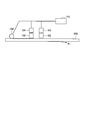
- FIG. 1 is a schematic diagram illustrating a configuration of the defect inspection apparatus 100.
- the defect inspection apparatus 100 includes an electromagnetic ultrasonic probe 102 including a plurality of (e.g., eight) coils arranged adjacent to each other and partially overlapping, an amplifier 104 (not shown in FIG. 1), a measure.
- a ring roll 106, a tip detection sensor 108, a calculation device 110, a display device 120, and an alarm device 130 are provided.
- a steel plate 200 that is an inspection object is placed on a passing plate table and is conveyed in the direction of arrow A1 in FIG. 1 by driving a roller of the passing plate table.
- the electromagnetic ultrasonic probe 102 detects an internal defect 202 of the steel plate 200 by transmitting and receiving electromagnetic ultrasonic waves by the eight coils, and a plurality of electromagnetic ultrasonic probes 102 are arranged in the width direction of the steel plate 200.
- the electromagnetic ultrasonic probes 102 are arranged in two rows in the conveying direction of the steel plate 200, and eight electromagnetic ultrasonic waves are respectively arranged in the upstream and downstream rows in the conveying direction.
- a probe 102 is arranged. Further, as shown in FIG.
- the eight electromagnetic ultrasonic probes 102 in the upstream and downstream rows are arranged so that the positions in the width direction of the steel plate 200 are different from each other, and are adjacent to each other on the upstream side.
- the electromagnetic ultrasonic probe 102 on the downstream side is located in the middle of the electromagnetic ultrasonic probe 102 to be operated.
- FIG. 2 is a schematic diagram showing a state seen from the direction of arrow A2 in FIG.
- the electromagnetic ultrasonic probe 102 is disposed close to the upper part of the steel plate 200. Air is supplied from the bottom surface of the electromagnetic ultrasonic probe 102 toward the steel plate 200, and this air causes a gap between the bottom surface of the electromagnetic ultrasonic probe 102 and the steel plate 200 to be about 0.5 mm. Have been adjusted so that.
- the amplifier 104 is arranged on the upper part of the electromagnetic ultrasonic probe 102, and a detection signal output from the electromagnetic ultrasonic probe 102 (more precisely, each coil provided in the electromagnetic ultrasonic probe 102). Output signal).
- the electromagnetic ultrasonic probe 102 generates ultrasonic vibrations on the surface of the steel plate 200 by each coil, and the eddy current generated by the vibration of the ultrasonic waves reflected from the bottom surface of the steel plate 200 under a static magnetic field is generated by each coil. Detect. Thereby, the echo level (B echo) of the ultrasonic vibration reflected on the bottom surface is detected.
- the internal defect 202 shown in FIG. 1 occurs in the steel plate 200, the ultrasonic vibration is reflected by the internal defect 202, and the ultrasonic vibration reflected by the internal defect 202 is detected by the electromagnetic ultrasonic probe 102.
- the defect 202 When the internal defect 202 has occurred, the echo level (F echo) of the reflected ultrasonic vibration changes, so that the internal defect 202 is based on the ratio of the F echo signal intensity to the B echo signal intensity (F / B ratio).
- the defect 202 can be evaluated (classified).
- the arithmetic device 110 has a function of supplying a high frequency current (high frequency signal) to each electromagnetic ultrasonic probe 102. That is, the arithmetic unit 110 supplies a high-frequency current for generating ultrasonic vibration in the steel plate 200 to each of the eight coils provided in each electromagnetic ultrasonic probe 102. In addition, the arithmetic unit 110 receives each coil based on the output signal of each electromagnetic ultrasonic probe 102 (that is, the output signal of each coil provided in each electromagnetic ultrasonic probe 102). The signal intensity of the F echo and the B echo of the ultrasonic vibration is calculated, and the internal defect 202 of the steel plate 200 is evaluated based on the calculation result.
- the calculation device 110 includes a correction value acquisition unit 112, an operation state determination unit 114, a correction execution unit 116, an F / B calculation unit (ratio calculation unit) 117, and a defect evaluation unit 118.
- the correction value storage unit 119 is provided.
- the operating state determination unit 114 determines the operating states of all eight coils for each electromagnetic ultrasonic probe 102. Specifically, the operating state determination unit 114 has a self-diagnosis function that determines that a coil that could not detect the F echo and the B echo is a failure (that is, a non-operating state).
- the correction execution unit 116 corrects the signal intensity of the B echo received by each coil based on the determination result of the operation state of each coil by the operation state determination unit 114. Although details will be described later, the correction execution unit 116 determines that the operation state determination unit 114 determines that any one of the eight coils is adjacent to any one of the eight coils. The signal intensity of the B echo received by the first coil is corrected with the first correction value.
- the correction execution unit 116 determines the signal intensity of the B echo received by the arbitrary coil. Correction is performed with the second correction value. Further, when the operation state determination unit 114 determines that the two coils adjacent to the arbitrary coil are operating, the correction execution unit 116 determines the signal intensity of the B echo received by the arbitrary coil. Correction is performed with the third correction value. Note that each of the above corrections is performed for all the electromagnetic ultrasonic probes 102.
- the F / B calculation unit 117 calculates the F / B ratio between the signal intensity of the F echo and the corrected signal intensity of the B echo for each coil. The calculation of the F / B ratio is performed for all of the electromagnetic ultrasonic probes 102.
- the defect evaluation unit 118 evaluates the internal defect 202 of the steel plate 200 based on the F / B ratio calculation result by the F / B calculation unit 117.
- the correction value acquisition unit 112 outputs the signal intensity of the B echo received by the arbitrary coil while two coils adjacent to the arbitrary coil are operating among the eight coils, and the arbitrary coil.
- the first correction value is acquired based on the difference from the signal intensity of the B echo received by the arbitrary coil while only one adjacent coil is operating.
- the correction value acquisition unit 112 receives the signal intensity of the B echo received by the arbitrary coil while the two coils adjacent to the arbitrary coil are in operation, and 2 adjacent to the arbitrary coil.
- the second correction value is acquired based on a difference from the signal intensity of the B echo received by the arbitrary coil in a state where the two coils are not operating.
- the correction value storage unit 119 stores the first correction value and the second correction value acquired by the correction value acquisition unit 112. In addition, acquisition of said 1st correction value and said 2nd correction value is carried out in advance before the actual defect inspection, one electromagnetic ultrasonic probe 102 and the sample of the steel plate 200 which is a test object. Used experimentally. Details of the method of acquiring the first correction value and the second correction value will be described later.
- the display device 120 displays the evaluation result (class classification) of the internal defect 202 based on the evaluation result of the internal defect 202 by the arithmetic device 110. Further, the alarm device 130 issues an alarm when the F / B ratio of the internal defect 202 exceeds the reference value.
- the steel plate 200 in which the internal defect 202 exceeding the reference value is detected leaves the normal conveyance path and is subjected to further detailed inspection.
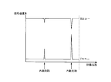
- FIG. 3A shows the relationship between the flaw detection position in the conveyance direction of the steel plate 200 and the signal intensity of the F echo and the B echo.
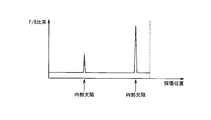
- FIG. 3B shows the relationship between the flaw detection position and the F / B ratio.
- the signal intensity of the F echo increases according to the size of the internal defect 202, and the signal intensity of the B echo decreases.
- the F / B ratio increases at the flaw detection position where the internal defect 202 has occurred compared to the flaw detection position where the internal defect 202 has not occurred.
- the F / B ratio increases as the internal defect 202 increases. Therefore, based on the F / B ratio, it can be detected whether or not the internal defect 202 has occurred, and the size and position of the internal defect 202 can be evaluated.
- the gap between the electromagnetic ultrasonic probe 102 and the surface of the steel plate 200 changes, the signal intensity of the B echo and the F echo changes, but by calculating the F / B ratio, the B echo and F due to the change in the gap are calculated.
- the amount of change in echo signal intensity can be offset.
- by evaluating the internal defect 202 based on the F / B ratio even if the F echo and the B echo contain noise, the noise can be canceled out, and the internal defect 202 is increased. The accuracy can be evaluated.
- Detection signals output from the plurality of electromagnetic ultrasonic probes 102 arranged in the width direction of the steel plate 200 are transmitted to the arithmetic device 110.
- a position signal output from the measuring roll 106 that measures the position from the tip of the steel plate 200 is also transmitted to the arithmetic device 110.
- the tip detection sensor 108 detects the tip position of the steel plate 200, and the tip position serves as a reference when the measuring roll 106 detects the position of the steel plate 200.
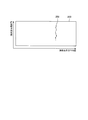
- the arithmetic unit 110 synchronizes the F / B ratio signal and the position signal, and creates a defect map indicating the position where the internal defect 202 occurs in the steel plate 200 as shown in FIG.
- the width in the steel plate width direction of one electromagnetic ultrasonic probe 102 is about 100 mm, and the distance between adjacent electromagnetic ultrasonic probes 102 cannot be made zero. Therefore, in order to eliminate the undetected area, the electromagnetic ultrasonic probes 102 are arranged in two rows in the conveying direction of the steel plate 200 as described above, and the positions in the width direction of the steel plate 200 are different from each other in the two rows. It is arranged in a so-called staggered arrangement.
- the arithmetic device 110 is configured to detect the detection signals output from the plurality of electromagnetic ultrasonic probes 102 arranged in this manner, and the position of the steel plate 200 that moves on the through plate table that conveys the steel plate 200 with acceleration / deceleration. Are recognized, an accurate defect position is recognized, and a defect map as shown in FIG. 4 is created. As a result, it is possible to instantly grasp how much size of the internal defect 202 has occurred at which position in the conveyance direction of the steel plate 200.
- FIG. 5 is a schematic diagram showing a state in which ultrasonic vibration generated in the steel plate 200 by the electromagnetic ultrasonic probe 102 propagates inside the steel plate 200.
- each electromagnetic ultrasonic probe 102 for example, eight coils are arranged adjacent to each other and partially overlapped.
- FIG. 5 representatively shows only three coils 1 to 3 out of eight coils. The coils 1 to 3 are simultaneously transmitting and receiving ultrasonic waves in synchronization.
- FIG. 6 is a plan view of the three coils 1 to 3 as viewed from the direction of arrow A3 in FIG.
- the three coils 1 to 3 are illustrated as being arranged at regular intervals without overlapping, but actually, as illustrated in FIG. 6, the three coils 1 to 3 are illustrated.
- Eight coils including three coils 1 to 3 are arranged in a line on a printed circuit board (FPC) (not shown).
- FPC printed circuit board
- the electromagnetic ultrasonic probe 102 is provided with permanent magnets 102 a corresponding to the coils 1 to 3.
- a magnetic field M ⁇ b> 1 that fluctuates at a high frequency is generated on the surface of the steel plate 200.
- An induced current I 1 is generated on the surface of the steel plate 200 in a direction that cancels the magnetic field M 1 .
- the Lorentz force F is generated by a current I 1 flows through the conductor in a static magnetic field M2 generated by the permanent magnets 102a (steel 200). Since the Lorentz force F fluctuates in synchronization with the high-frequency current flowing through the coil 2, the surface of the steel plate 200 vibrates due to the Lorentz force F, thereby generating ultrasonic vibration.
- the ultrasonic vibration generated by the coil 2 is reflected from the bottom surface of the steel plate 200.
- the ultrasonic echo level (B echo) of the coil 2 reflected from the bottom surface is received by the coil 2 that has generated ultrasonic vibration, and is also received by the coils 1 and 3 adjacent to the coil 2. This is due to the fact that the ultrasonic waves propagate far away and the adjacent coils partially overlap each other as shown in FIG.
- the echo level (F echo) of the ultrasonic vibration reflected by the internal defect 202 is also received by the coil 2.
- the coil 2 receives reflected waves (F echo and B echo) by detecting an eddy current generated by the reflected ultrasonic wave oscillating under the static magnetic field of the permanent magnet 102.
- the coils 1 and 3 transmit and receive ultrasonic waves in synchronization with the coil 2, the coil 2 generates both the adjacent two coils 1 and 3 in addition to the B echo of the ultrasonic vibration generated by itself. The B echo of the ultrasonic vibration that has been made is also received.
- the coil 1 when the coil 1 is located at the end of eight coils, the coil 2 is the only coil adjacent to the coil 1. Therefore, the coil 1 receives the B echo of the ultrasonic vibration generated by one adjacent coil 2 in addition to the B echo of the ultrasonic vibration generated by itself. As a result, the signal intensity of the B echo received by the coil 1 is smaller than the signal intensity of the B echo received by the coil 2.
- the signal intensity of the adjacent F echo received by any coil is negligibly small, but the adjacent B echo (adjacent coil) received by the arbitrary coil is small.
- the signal intensity of the B echo that should be received by the user is so large that it cannot be ignored.
- the signal intensity of the B echo received by the coil 1 is smaller than the signal intensity of the B echo received by the coils 2 and 3. 1 has an excessive F / B ratio than coils 2 and 3.
- any coil can be received in addition to the B echo that should be received by itself.
- Another coil adjacent to this also receives the B echo to be received by the main body.
- the ultrasonic wave generation timing of each coil cannot be shifted. Therefore, an arbitrary coil always receives the B echo that should be received by the adjacent coil.
- the underestimation of the internal defect 202 cannot detect the internal defect 202 and leads to the outflow of the defective steel plate 200. Therefore, a reference size that is recognized as the internal defect 202 is set, and the F / B ratio of the coil that is detected as the lowest F / B ratio value is used as the determination threshold value. Thereby, the F / B ratio when the reference size is detected by another coil is equal to or greater than the determination threshold value, and it is possible to reliably prevent the situation in which the internal defect 202 is not detected by the underestimation. In the example shown in FIG. 5, since the F / B ratio of the coil 2 is lower than the coil 1 F / B ratio, the F / B ratio when the coil 2 detects the reference size becomes the determination threshold value.
- FIG. 7 shows eight coils as ch1 to ch8, and 14 examples when the transmission of ultrasonic waves in each ch is turned on (ON: operating state) or turned off (OFF: non-operating state) (level 1).
- the coil ch4 is a data collection target coil for detecting the B echo, and is always on.
- FIG. 8 is a characteristic diagram showing a measured value (dB) of the signal intensity of the B echo of the coil ch4 that is the data collection target ch for each of the levels 1 to 14 shown in FIG.
- Level 1 of FIG. 7 the case where all the ultrasonic transmissions of the eight coils (ch1 to 8) are turned on is shown.
- Level 2 shows a case where only the leftmost coil ch1 is turned off and the other coils are turned on.
- Level 3 shows a case where the coils ch1 and ch8 at both ends are turned off and the other coils are turned on. From level 4 to level 8, the coils that are further away from the coil ch4 are sequentially turned off.
- Level 9 shows a case where all except the coil ch4 are turned off. Furthermore, after level 9, one of the coils outside ch3 and ch5 is sequentially turned on.
- the data collection target coil is ch4.
- ch1 or ch8 has only one adjacent coil, so one of the adjacent coils is always present. Equivalent to the case of off (non-operating state). Therefore, in the coil ch1, even if the adjacent coil ch2 is on, the signal intensity of the B echo is reduced by 2 dB. For the coil ch1, when the adjacent coil ch2 is off, the signal intensity of the B echo is reduced by 4 dB. Similarly, for the coil ch8, even if the adjacent coil ch7 is on, the signal intensity of the B echo is reduced by 2 dB, and when the adjacent coil ch7 is off, the reduction is 4 dB. As described above, regarding the coil located at the end portion, it can be seen that the signal intensity of the B echo is lowered even if the adjacent coil is normal.
- a difference of 4 dB in the signal intensity of the B echo corresponds to a difference between a light defect and a medium defect.
- this difference cannot be ignored in actual operation. Therefore, since the difference in the signal intensity of the B echo affects the evaluation level of the internal defect 202, it is necessary to reliably suppress overestimation of the signal intensity.
- the signal intensity of the B echo received by each coil is corrected according to the operating state of each coil.
- the signal intensity of the B echo received by each coil is made uniform, the error of the detection level of the internal defect 202 when evaluated based on the F / B ratio is eliminated, and the evaluation of the internal defect 202 is stabilized. It is possible to make it.
- the coil is disconnected due to an impact when the electromagnetic ultrasonic probe 102 and the steel plate 200 come into contact with each other. It is possible. Even when an arbitrary coil is turned off due to such factors, it is possible to continuously perform defect inspection by performing the above-described correction on the signal intensity of the B echo.
- the signal intensity of the B echo received by each coil becomes a normal value (uniform value), and therefore the internal defect 202 is caused by an abnormal signal intensity (non-uniform signal intensity). It is possible to reliably prevent the overestimation of.
- each coil adjacent to an arbitrary coil is turned on / off, and the correlation between the on / off state of each adjacent coil and the decrease in the signal intensity of the B echo received by the arbitrary coil Is acquired in advance, the signal intensity of the B echo received by each coil can be corrected according to the operating state of each coil.
- B received by an arbitrary coil Correction was performed by adding 2 dB to the echo signal intensity and adding 4 dB to the B echo signal intensity received by the arbitrary coil when two of the coils adjacent to the arbitrary coil are not operating.
- the calculation device 110 includes the correction value acquisition unit 112, the operating state determination unit 114, the correction execution unit 116, the F / B calculation unit 117, the defect evaluation unit 118, and the correction value storage unit 119. It has.
- the correction value acquisition unit 112 acquires the characteristics of FIG. 8 for the levels 1 to 14 in advance, and the signal intensity of the B echo received by the arbitrary coil with one of the coils adjacent to the arbitrary coil turned off. The amount of decrease is acquired as the first correction value. Further, the correction value acquisition unit 112 acquires, as the second correction value, the amount of decrease in the signal intensity of the B echo received by the arbitrary coil when two of the coils adjacent to the arbitrary coil are off.
- the correction value storage unit 119 stores the first correction value and the second correction value acquired by the correction value acquisition unit 112. As described above, the acquisition of the first correction value and the second correction value is performed using one electromagnetic ultrasonic probe 102 and a sample of the steel plate 200 in advance prior to actual defect inspection. Done experimentally.
- the operating state determination unit 114 determines the operating states of the eight coils ch1 to ch8 for each electromagnetic ultrasonic probe 102.
- the correction execution unit 116 performs correction according to the operation state determination result of each coil by the operation state determination unit 114.
- the correction execution unit 116 sets the first correction value to the signal intensity of the B echo received by the arbitrary coil.
- 2 dB which is a preset value is added.
- the correction execution unit 116 sets a value set in advance as a second correction value for the signal intensity of the B echo received by the upper arbitrary coil. Add 4 dB.
- the correction execution unit 116 sets the third correction value to zero when both coils adjacent to the arbitrary coil are operating, and the B echo signal received by the arbitrary coil. Do not correct the intensity. Note that each of the above corrections is performed for all the electromagnetic ultrasonic probes 102.
- the F / B calculation unit 117 calculates a ratio (F / B ratio) between the signal intensity of the F echo and the corrected signal intensity of the B echo (F / B ratio) for each of the coils.
- the calculation of the F / B ratio is performed for all of the electromagnetic ultrasonic probes 102.
- the defect evaluation unit 118 evaluates the internal defect 202 of the steel plate 200 based on the F / B ratio calculation result by the F / B calculation unit 117.
- 1 can be configured by a circuit (hardware) or a central processing unit such as a CPU and a program (software) for causing it to function.
- a circuit hardware
- a central processing unit such as a CPU
- a program software
- FIG. 9 is a flowchart showing a process for correcting the signal intensity of the B echo according to the present embodiment.
- the correction value acquisition unit 112 acquires the characteristics of FIG. 8 for the levels 1 to 14 in advance prior to the actual defect inspection, and one of the coils adjacent to an arbitrary coil is in an off state.
- the amount of decrease in the received intensity of the B echo received by the arbitrary coil is acquired as the first correction value, and the B echo received by the arbitrary coil with two of the coils adjacent to the arbitrary coil turned off. Is obtained as the second correction value.
- the operating state determination unit 114 determines the operating states of the eight coils ch1 to ch8 for each electromagnetic ultrasonic probe 102. Specifically, first, in step S12, it is determined whether or not both of the two coils adjacent to an arbitrary coil are inactive. If both of the two coils are not inactive, the process proceeds to step S14. When both of the two coils are not operating, the process proceeds to step S20, and the correction execution unit 116 adds the second correction value (4 dB) to the signal intensity of the B echo received by any coil.
- step S ⁇ b> 14 the operating state determination unit 114 determines, for each electromagnetic ultrasonic probe 102, whether only one coil adjacent to an arbitrary coil is non-operating, and only one adjacent coil is detected. If is not in operation, the process proceeds to step S18.
- step S18 the correction execution unit 116 adds the first correction value (2 dB) to the signal intensity of the B echo received by the arbitrary coil.
- step S14 if one adjacent coil is not inactive, the process proceeds to step S16.
- step S16 since both of the two adjacent coils are operating, in step S16, the signal intensity of the B echo received by the arbitrary coil is not corrected.
- the correction execution unit 116 sets the third correction value to zero and does not correct the signal intensity of the B echo received by the arbitrary coil.
- the present embodiment it is possible to compensate for the decrease in the signal intensity of the B echo due to the influence of adjacent coils, normalize the signal intensity of the B echo received by each coil, and make it uniform. Can be realized. Thereby, the rejection determination by the overdetection of the internal defect 202 can be reduced reliably. In addition, the S / N ratio can be improved even in a terminal coil having few adjacent coils, and the failure determination due to a pseudo defect can be greatly reduced.
Landscapes
- Physics & Mathematics (AREA)
- General Health & Medical Sciences (AREA)
- Biochemistry (AREA)
- Pathology (AREA)
- Health & Medical Sciences (AREA)
- Life Sciences & Earth Sciences (AREA)
- Chemical & Material Sciences (AREA)
- Analytical Chemistry (AREA)
- Immunology (AREA)
- Electromagnetism (AREA)
- General Physics & Mathematics (AREA)
- Engineering & Computer Science (AREA)
- Mechanical Engineering (AREA)
- Acoustics & Sound (AREA)
- Investigating Or Analyzing Materials By The Use Of Ultrasonic Waves (AREA)
Abstract
Description
本願は、2012年12月20日に、日本に出願された特願2012-278563号に基づき優先権を主張し、その内容をここに援用する。
以上のように、従来の電磁超音波探触子において、互いに隣接して一部が重なり合うように複数のコイルが配列されるような構成が採用される場合、検査対象物の内部欠陥を正確に評価することは困難であった。
本発明は、上述した事情に鑑みてなされたものであり、電磁超音波探触子において、互いに隣接して一部が重なり合うように複数のコイルが配列されるような構成が採用される場合であっても、検査対象物の内部欠陥を正確に評価可能な欠陥検査方法及び欠陥検査装置を提供することを目的とする。
本発明は、上記課題を解決して係る目的を達成するために、以下のような手段を採用する。すなわち、
(1)本発明の一態様に係る欠陥検査方法は、電磁超音波探触子において互いに隣接して一部が重なり合うように配列された複数のコイルに対して高周波信号を与えて、検査対象物に超音波振動を発生させる第1工程と;前記超音波振動のBエコーを前記複数のコイルのそれぞれで受信する第2工程と;前記超音波振動のFエコーを前記複数のコイルのそれぞれで受信する第3工程と;前記複数のコイルのそれぞれで受信された前記Bエコーの信号強度を、前記複数のコイルの稼働状態に基づいて補正する第4工程と;前記Fエコーの信号強度と補正後の前記Bエコーの信号強度との比率を、前記複数のコイルのそれぞれについて計算し、その計算結果に基づいて前記検査対象物の内部欠陥を評価する第5工程と;を有する。
以下に添付図面を参照しながら、本発明の好適な実施の形態について詳細に説明する。なお、本明細書及び図面において、実質的に同一の機能構成を有する構成要素については、同一の符号を付することにより重複説明を省略する。
まず、図1及び図2を参照して、本発明の一実施形態に係る欠陥検査装置(電磁超音波装置:EMAT)100の構成について説明する。図1は、欠陥検査装置100の構成を示す模式図である。欠陥検査装置100は、互いに隣接して一部が重なり合うように配列された複数(例えば8個)のコイルを含む電磁超音波探触子102と、アンプ104(図1において図示省略)と、メジャーリングロール106と、先端検出センサー108と、演算装置110と、表示装置120と、警報装置130とを備えている。
図1に示すように、例えば、電磁超音波探触子102は、鋼板200の搬送方向に2列に配置されており、搬送方向の上流側と下流側の列にそれぞれ8個の電磁超音波探触子102が配置されている。また、図1に示すように、上流側と下流側の列の8個の電磁超音波探触子102は、鋼板200の幅方向の位置がそれぞれ異なるように配置されており、上流側の隣接する電磁超音波探触子102の中間に下流側の電磁超音波探触子102が位置している。
このように複数の電磁超音波探触子102を千鳥状に配置することで、上流側の電磁超音波探触子102では検出できない電磁超音波探触子102間に位置する内部欠陥202を、下流側の電磁超音波探触子102で確実に検出することができる。
演算装置110は、各電磁超音波探触子102に対して高周波電流(高周波信号)を供給する機能を有する。つまり、演算装置110は、各電磁超音波探触子102に設けられた8個のコイルのそれぞれに、鋼板200に超音波振動を発生させるための高周波電流を供給する。
また、この演算装置110は、各電磁超音波探触子102の出力信号(つまり、各電磁超音波探触子102に設けられた各コイルの出力信号)に基づいて、各コイルのそれぞれで受信された超音波振動のFエコー及びBエコーの信号強度を算出し、その算出結果に基づいて鋼板200の内部欠陥202を評価する。
補正実行部116は、稼働状態判定部114による各コイルの稼働状態の判定結果に基づいて、各コイルのそれぞれで受信されたBエコーの信号強度を補正する。
詳細は後述するが、この補正実行部116は、稼働状態判定部114が、8個のコイルのうち、任意のコイルに隣接する1つのコイルのみが稼働していると判定した場合は、上記任意のコイルで受信されたBエコーの信号強度を第1の補正値で補正する。
また、補正実行部116は、稼働状態判定部114が、上記任意のコイルに隣接する2つのコイルが稼働していないと判定した場合は、上記任意のコイルで受信されたBエコーの信号強度を第2の補正値で補正する。
さらに、補正実行部116は、稼働状態判定部114が、上記任意のコイルに隣接する2つのコイルが稼働していると判定した場合は、上記任意のコイルで受信されたBエコーの信号強度を第3の補正値で補正する。
なお、上記の各補正は、各電磁超音波探触子102の全てについて行われる。
また、この補正値取得部112は、上記任意のコイルに隣接する2つのコイルが稼働している状態で上記任意のコイルで受信されたBエコーの信号強度と、上記任意のコイルに隣接する2つのコイルが稼働していない状態で上記任意のコイルで受信されたBエコーの信号強度との差分に基づいて、上記第2の補正値を取得する。
補正値記憶部119は、補正値取得部112が取得した上記の第1の補正値及び第2の補正値を記憶する。
なお、上記の第1の補正値及び第2の補正値の取得は、実際の欠陥検査に先立って、予め、1つの電磁超音波探触子102と検査対象物である鋼板200のサンプルとを用いて実験的に行われる。第1の補正値及び第2の補正値の取得方法の詳細については後述する。
先端検出センサー108は、鋼板200の先端位置を検出し、その先端位置はメジャーリングロール106が鋼板200の位置を検出する際の基準となる。演算装置110は、F/B比率の信号と位置信号との同期をとり、図4に示すような、鋼板200における内部欠陥202の発生位置を示す欠陥マップを作成する。
図5は、電磁超音波探触子102によって鋼板200に発生した超音波振動が鋼板200の内部を伝播する様子を示す模式図である。上記のように、各電磁超音波探触子102ごとに、例えば8個のコイルが、互いに隣接して一部が重なるように配列されている。図5では、8個のコイルのうち、3つのコイル1~3のみを代表的に図示している。各コイル1~3は、同期をとって超音波の送受信を同時に行っている。
このように、任意のコイルが受信する隣接Fエコー(隣接するコイルが本来受信すべきFエコー)の信号強度は、無視できるほどに小さいが、任意のコイルが受信する隣接Bエコー(隣接するコイルが本来受信すべきBエコー)の信号強度は、無視できないほど大きい。
内部欠陥202の過小評価は、内部欠陥202を検出することができず、不良のある鋼板200の流出に繋がる。このため、内部欠陥202として認識する基準のサイズを設定し、内部欠陥202の基準のサイズを最も低いF/B比率の値として検出したコイルのF/B比率を判定しきい値として使用する。
これにより、他のコイルで基準のサイズを検出したときのF/B比率は判定しきい値以上となり、内部欠陥202が過小評価により検出されない事態を確実に防ぐことができる。図5に示す例では、コイル2のF/B比率がコイル1F/B比率よりも低いので、コイル2が基準のサイズを検出したときのF/B比率が判定しきい値となる。この場合、少なくともコイル1のF/B比率は、コイル2のF/B比率よりも大きくなるので、コイル1のF/B比率に基づく評価を行うと、内部欠陥202を過大評価することになる。従って、端部に位置するコイル1のF/B比率に基づいて内部欠陥202を正常に評価することが困難となる。
[3.本実施形態の具体的構成例]
本実施形態では、任意コイルに対する隣接コイルの影響を抑えるため、各コイルの稼働状態に応じて、各コイルで受信されたBエコーの信号強度に補正を加える。図7は、8個のコイルをch1~ch8として示し、各chにおける超音波の送信をオン(ON:稼働状態)またはオフ(OFF:非稼働状態)させた場合の14通りの例(水準1~14)を示している。コイルch4は、Bエコーを検出するデータ採取対象のコイルであり、常にオンである。図8は、図7に示す水準1~14のそれぞれについて、データ採取対象chであるコイルch4のBエコーの信号強度を実測した値(dB)を示す特性図である。
また、コイルch1については、隣接するコイルch2がオフの場合はBエコーの信号強度に4dBの低下が生じる。同様に、コイルch8については、隣接するコイルch7がオンであってもBエコーの信号強度に2dBの低下が生じ、隣接するコイルch7がオフの場合は4dBの低下が生じる。このように、端部に位置するコイルについては、隣接するコイルが正常であってもBエコーの信号強度に低下が生じることが判る。
以上のように、本実施形態によれば、各コイルで受信されたBエコーの信号強度が正常な値(均一な値)となるので、正常でない信号強度(均一でない信号強度)によって内部欠陥202の過大評価が行われてしまうことを確実に抑止することが可能となる。
補正値記憶部119は、補正値取得部112が取得した第1の補正値及び第2の補正値を記憶する。
なお、前述のように、第1の補正値及び第2の補正値の取得は、実際の欠陥検査に先立って、予め、1つの電磁超音波探触子102と鋼板200のサンプルとを用いて実験的に行われる。
補正実行部116は、稼働状態判定部114による各コイルの稼働状態判定結果に応じて補正を実行する。上述の例では、補正実行部116は、任意のコイルに隣接するコイルの1つのみが稼働している場合は、上記任意のコイルで受信されたBエコーの信号強度に、第1の補正値として予め設定した値である2dBを加算する。
また、補正実行部116は、任意のコイルに隣接するコイルの2つが稼働していない場合は、上位任意のコイルで受信されたBエコーの信号強度に、第2の補正値として予め設定した値である4dBを加算する。
また、補正実行部116は、任意のコイルに隣接するコイルが2つとも稼働している場合は、第3の補正値をゼロに設定して、上記任意のコイルで受信されたBエコーの信号強度を補正しない。なお、上記の各補正は、各電磁超音波探触子102の全てについて行われる。
図9は、本実施形態に係るBエコーの信号強度の補正処理を示すフローチャートである。先ず、ステップS10では、補正値取得部112が、実際の欠陥検査に先立って、事前に水準1~14について図8の特性を取得し、任意のコイルに隣接するコイルの1つがオフの状態で上記任意のコイルで受信されたBエコーの受信強度の低下量を第1の補正値として取得し、任意のコイルに隣接するコイルの2つがオフの状態で上記任意のコイルで受信されたBエコーの信号強度の低下量を第2の補正値として取得する。
102 電磁超音波探触子
104 アンプ
106 メジャーリングロール
108 先端検出センサー
110 演算装置
112 補正値取得部
114 稼働状態判定部
116 補正判定部
117 F/B演算部(比率演算部)
118 欠陥評価部
119 補正値記憶部
120 表示装置
130 警報装置
200 鋼板(検査対象物)
202 内部欠陥
1~3、ch1~ch8 コイル
Claims (9)
-
電磁超音波探触子において互いに隣接して一部が重なり合うように配列された複数のコイルに対して高周波信号を与えて、検査対象物に超音波振動を発生させる第1工程と;
前記超音波振動のBエコーを前記複数のコイルのそれぞれで受信する第2工程と;
前記超音波振動のFエコーを前記複数のコイルのそれぞれで受信する第3工程と;
前記複数のコイルのそれぞれで受信された前記Bエコーの信号強度を、前記複数のコイルの稼働状態に基づいて補正する第4工程と;
前記Fエコーの信号強度と補正後の前記Bエコーの信号強度との比率を、前記複数のコイルのそれぞれについて計算し、その計算結果に基づいて前記検査対象物の内部欠陥を評価する第5工程と;
を有することを特徴とする欠陥検査方法。 - 前記第4工程において、
任意のコイルに隣接する1つのコイルのみが稼働している場合は、前記任意のコイルで受信された前記Bエコーの信号強度を第1の補正値で補正し、
前記任意のコイルに隣接する2つのコイルが稼働していない場合は、前記任意のコイルで受信された前記Bエコーの信号強度を第2の補正値で補正し、
前記任意のコイルに隣接する2つのコイルが稼働している場合は、前記任意のコイルで受信された前記Bエコーの信号強度を第3の補正値で補正する、
ことを特徴とする請求項1に記載の欠陥検査方法。 - 前記第1の補正値は前記第2の補正値よりも小さく、
前記任意のコイルに隣接する2つのコイルが稼働している場合は、前記第3の補正値をゼロに設定して、前記任意のコイルで受信された前記Bエコーの信号強度を補正しないことを特徴とする請求項2に記載の欠陥検査方法。 - 前記第1工程の前に、
前記任意のコイルに隣接する2つのコイルが稼働している状態で前記任意のコイルで受信された前記Bエコーの信号強度と、前記任意のコイルに隣接する1つのコイルのみが稼働している状態で前記任意のコイルで受信された前記Bエコーの信号強度との差分に基づいて、前記第1の補正値を取得する工程と;
前記任意のコイルに隣接する2つのコイルが稼働している状態で前記任意のコイルで受信された前記Bエコーの信号強度と、前記任意のコイルに隣接する2つのコイルが稼働していない状態で前記任意のコイルで受信された前記Bエコーの信号強度との差分に基づいて、前記第2の補正値を取得する工程と;
を更に有することを特徴とする請求項3に記載の欠陥検査方法。 - 互いに隣接して一部が重なり合うように配列された複数のコイルを含む電磁超音波探触子と;
前記複数のコイルのそれぞれに、検査対象物に超音波振動を発生させるための高周波信号を供給すると共に、前記複数のコイルのそれぞれの出力信号に基づいて、前記複数のコイルのそれぞれで受信された、前記超音波振動のFエコー及びBエコーの信号強度を算出し、その算出結果に基づいて前記検査対象物の内部欠陥を評価する演算装置と;
を備え、
前記演算装置は、
前記複数のコイルの稼働状態を判定する稼働状態判定部と、
前記複数のコイルの稼働状態に基づいて、前記複数のコイルのそれぞれで受信された前記Bエコーの信号強度を補正する補正実行部と、
前記Fエコーの信号強度と補正後の前記Bエコーの信号強度との比率を、前記複数のコイルのそれぞれについて計算する比率演算部と、
前記比率演算部による前記比率の計算結果に基づいて前記検査対象物の内部欠陥を評価する欠陥評価部と、
を備えることを特徴とする欠陥検査装置。 - 前記補正実行部は、
前記稼働状態判定部が、任意のコイルに隣接する1つのコイルのみが稼働していると判定した場合は、前記任意のコイルで受信された前記Bエコーの信号強度を第1の補正値で補正し、
前記稼働状態判定部が、前記任意のコイルに隣接する2つのコイルが稼働していないと判定した場合は、前記任意のコイルで受信された前記Bエコーの信号強度を第2の補正値で補正し、
前記稼働状態判定部が、前記任意のコイルに隣接する2つのコイルが稼働していると判定した場合は、前記任意のコイルで受信された前記Bエコーの信号強度を第3の補正値で補正する
ことを特徴とする請求項5に記載の欠陥検査装置。 - 前記第1の補正値は前記第2の補正値よりも小さく、
前記補正実行部は、前記稼働状態判定部が、前記任意のコイルに隣接する2つのコイルが稼働していると判定した場合は、前記第3の補正値をゼロに設定して、前記任意のコイルで受信された前記Bエコーの信号強度を補正しないことを特徴とする請求項6に記載の欠陥検査装置。 - 前記演算装置は、
前記任意のコイルに隣接する2つのコイルが稼働している状態で前記任意のコイルで受信された前記Bエコーの信号強度と、前記任意のコイルに隣接する1つのコイルのみが稼働している状態で前記任意のコイルで受信された前記Bエコーの信号強度との差分に基づいて、前記第1の補正値を取得し、前記任意のコイルに隣接する2つのコイルが稼働している状態で前記任意のコイルで受信された前記Bエコーの信号強度と、前記任意のコイルに隣接する2つのコイルが稼働していない状態で前記任意のコイルで受信された前記Bエコーの信号強度との差分に基づいて、前記第2の補正値を取得する補正値取得部を更に備えることを特徴とする請求項7に記載の欠陥検査装置。 - 前記演算装置は、前記補正値取得部が取得した前記第1の補正値及び前記第2の補正値を記憶する補正値記憶部をさらに備えることを特徴とする請求項8に記載の欠陥検査装置。
Priority Applications (4)
| Application Number | Priority Date | Filing Date | Title |
|---|---|---|---|
| CN201380056483.0A CN104755920B (zh) | 2012-12-20 | 2013-09-27 | 缺陷检查方法及缺陷检查装置 |
| KR1020157010550A KR101561011B1 (ko) | 2012-12-20 | 2013-09-27 | 결함 검사 방법 및 결함 검사 장치 |
| JP2014502917A JP5534123B1 (ja) | 2012-12-20 | 2013-09-27 | 欠陥検査方法及び欠陥検査装置 |
| RU2015115975/28A RU2589491C1 (ru) | 2012-12-20 | 2013-09-27 | Способ исследования дефектов и устройство для исследования дефектов |
Applications Claiming Priority (2)
| Application Number | Priority Date | Filing Date | Title |
|---|---|---|---|
| JP2012278563 | 2012-12-20 | ||
| JP2012-278563 | 2012-12-20 |
Publications (1)
| Publication Number | Publication Date |
|---|---|
| WO2014097704A1 true WO2014097704A1 (ja) | 2014-06-26 |
Family
ID=50978054
Family Applications (1)
| Application Number | Title | Priority Date | Filing Date |
|---|---|---|---|
| PCT/JP2013/076211 Ceased WO2014097704A1 (ja) | 2012-12-20 | 2013-09-27 | 欠陥検査方法及び欠陥検査装置 |
Country Status (5)
| Country | Link |
|---|---|
| JP (1) | JP5534123B1 (ja) |
| KR (1) | KR101561011B1 (ja) |
| CN (1) | CN104755920B (ja) |
| RU (1) | RU2589491C1 (ja) |
| WO (1) | WO2014097704A1 (ja) |
Citations (5)
| Publication number | Priority date | Publication date | Assignee | Title |
|---|---|---|---|---|
| JPH10506183A (ja) * | 1994-07-01 | 1998-06-16 | ソニック フォース リミテッド ライアビリティ カンパニー | 電磁音響トランスジューサ |
| JP2002090349A (ja) * | 2000-09-21 | 2002-03-27 | Kansai Electric Power Co Inc:The | 電磁超音波による探傷方法及び電磁超音波探傷装置 |
| JP2005214686A (ja) * | 2004-01-28 | 2005-08-11 | Sumitomo Metal Ind Ltd | 電磁超音波探触子及び超音波探傷方法 |
| JP2008139325A (ja) * | 2008-01-16 | 2008-06-19 | Toshiba Corp | 超音波探傷装置 |
| JP2010258357A (ja) * | 2009-04-28 | 2010-11-11 | Kobe Steel Ltd | メアンダコイル、メアンダコイルの製造方法及び電磁超音波トランスデューサ |
Family Cites Families (13)
| Publication number | Priority date | Publication date | Assignee | Title |
|---|---|---|---|---|
| US4312231A (en) * | 1979-07-06 | 1982-01-26 | Nippon Steel Corporation | Apparatus for generating and detecting an electromagnetic ultrasonic wave |
| JPS5861462A (ja) * | 1981-10-07 | 1983-04-12 | Nippon Steel Corp | 角材の超音波探傷方法及び装置 |
| JPS5888653A (ja) * | 1981-11-24 | 1983-05-26 | Nippon Kokan Kk <Nkk> | 超音波探傷装置 |
| JPH02150765A (ja) * | 1988-11-30 | 1990-06-11 | Sumitomo Chem Co Ltd | 超音波探傷方法 |
| JPH0687052B2 (ja) * | 1989-01-24 | 1994-11-02 | 新日本製鐵株式会社 | 鋼板の超音波探傷装置 |
| US5675087A (en) * | 1994-02-15 | 1997-10-07 | The Babcock & Wilcox Company | Fastener characterization with an electromagnetic acoustic transducer |
| RU2149393C1 (ru) * | 1999-05-19 | 2000-05-20 | Зао "Алтек" | Способ ультразвукового контроля цилиндрических изделий |
| RU2184374C1 (ru) * | 2001-08-28 | 2002-06-27 | ОАО "Радиоавионика" | Ультразвуковой способ контроля головки рельсов |
| JP2004045124A (ja) | 2002-07-10 | 2004-02-12 | Mitsubishi Heavy Ind Ltd | 配管の非破壊検査方法 |
| JP2006276032A (ja) | 2006-06-08 | 2006-10-12 | Toshiba Corp | 配管検査方法および装置 |
| CN101839894B (zh) * | 2010-06-17 | 2013-12-18 | 奥瑞视(北京)科技有限公司 | 一种新型数字超声探伤系统和方法 |
| CN202049136U (zh) * | 2011-03-30 | 2011-11-23 | 大连海事大学 | 一种多通道高速并行超声波在线探伤通信系统 |
| CN102393422A (zh) * | 2011-08-22 | 2012-03-28 | 江苏省产品质量监督检验研究院 | 基于超声tofd的缺陷离线判别方法 |
-
2013
- 2013-09-27 KR KR1020157010550A patent/KR101561011B1/ko not_active Expired - Fee Related
- 2013-09-27 WO PCT/JP2013/076211 patent/WO2014097704A1/ja not_active Ceased
- 2013-09-27 RU RU2015115975/28A patent/RU2589491C1/ru active
- 2013-09-27 JP JP2014502917A patent/JP5534123B1/ja active Active
- 2013-09-27 CN CN201380056483.0A patent/CN104755920B/zh not_active Expired - Fee Related
Patent Citations (5)
| Publication number | Priority date | Publication date | Assignee | Title |
|---|---|---|---|---|
| JPH10506183A (ja) * | 1994-07-01 | 1998-06-16 | ソニック フォース リミテッド ライアビリティ カンパニー | 電磁音響トランスジューサ |
| JP2002090349A (ja) * | 2000-09-21 | 2002-03-27 | Kansai Electric Power Co Inc:The | 電磁超音波による探傷方法及び電磁超音波探傷装置 |
| JP2005214686A (ja) * | 2004-01-28 | 2005-08-11 | Sumitomo Metal Ind Ltd | 電磁超音波探触子及び超音波探傷方法 |
| JP2008139325A (ja) * | 2008-01-16 | 2008-06-19 | Toshiba Corp | 超音波探傷装置 |
| JP2010258357A (ja) * | 2009-04-28 | 2010-11-11 | Kobe Steel Ltd | メアンダコイル、メアンダコイルの製造方法及び電磁超音波トランスデューサ |
Also Published As
| Publication number | Publication date |
|---|---|
| CN104755920B (zh) | 2016-10-12 |
| KR20150048925A (ko) | 2015-05-07 |
| JP5534123B1 (ja) | 2014-06-25 |
| CN104755920A (zh) | 2015-07-01 |
| JPWO2014097704A1 (ja) | 2017-01-12 |
| KR101561011B1 (ko) | 2015-10-15 |
| RU2589491C1 (ru) | 2016-07-10 |
Similar Documents
| Publication | Publication Date | Title |
|---|---|---|
| JP5387718B2 (ja) | 磁気特性測定方法および磁気特性測定装置 | |
| EP3070467B1 (en) | Ultrasonic test system, ultrasonic test method and method of manufacturing aircraft part | |
| JP4960466B2 (ja) | 紙葉類処理装置 | |
| KR101700061B1 (ko) | 결함 검사 방법 및 결함 검사 장치 | |
| US7984649B2 (en) | Panel inspection apparatus and inspection method | |
| JP5112942B2 (ja) | 超音波探傷方法及び装置 | |
| CN104903719B (zh) | 缺陷位置修正方法 | |
| JP5534123B1 (ja) | 欠陥検査方法及び欠陥検査装置 | |
| JP4673686B2 (ja) | 表面検査方法およびその表面検査装置 | |
| JP2001059836A (ja) | 渦流探傷方法および装置 | |
| JP2008151588A (ja) | 二層ベローズの欠陥評価方法及びこれに用いる渦流探傷装置 | |
| JP2002296250A (ja) | 内部欠陥検出方法 | |
| JP4657154B2 (ja) | 電磁誘導型検査方法及び電磁誘導型検査装置 | |
| JP5765140B2 (ja) | 磁気特性測定方法および磁気特性測定装置 | |
| JP2011180011A (ja) | 金属薄板の非破壊検査方法及びその非破壊検査装置 |
Legal Events
| Date | Code | Title | Description |
|---|---|---|---|
| ENP | Entry into the national phase |
Ref document number: 2014502917 Country of ref document: JP Kind code of ref document: A |
|
| 121 | Ep: the epo has been informed by wipo that ep was designated in this application |
Ref document number: 13865533 Country of ref document: EP Kind code of ref document: A1 |
|
| ENP | Entry into the national phase |
Ref document number: 20157010550 Country of ref document: KR Kind code of ref document: A |
|
| NENP | Non-entry into the national phase |
Ref country code: DE |
|
| ENP | Entry into the national phase |
Ref document number: 2015115975 Country of ref document: RU Kind code of ref document: A |
|
| 122 | Ep: pct application non-entry in european phase |
Ref document number: 13865533 Country of ref document: EP Kind code of ref document: A1 |