WO2014097610A1 - 振動制御装置、電子機器、および振動制御方法 - Google Patents
振動制御装置、電子機器、および振動制御方法 Download PDFInfo
- Publication number
- WO2014097610A1 WO2014097610A1 PCT/JP2013/007395 JP2013007395W WO2014097610A1 WO 2014097610 A1 WO2014097610 A1 WO 2014097610A1 JP 2013007395 W JP2013007395 W JP 2013007395W WO 2014097610 A1 WO2014097610 A1 WO 2014097610A1
- Authority
- WO
- WIPO (PCT)
- Prior art keywords
- frequency
- vibration
- touch panel
- sound
- dominant
- Prior art date
- Legal status (The legal status is an assumption and is not a legal conclusion. Google has not performed a legal analysis and makes no representation as to the accuracy of the status listed.)
- Ceased
Links
Images







Classifications
-
- G—PHYSICS
- G06—COMPUTING OR CALCULATING; COUNTING
- G06F—ELECTRIC DIGITAL DATA PROCESSING
- G06F3/00—Input arrangements for transferring data to be processed into a form capable of being handled by the computer; Output arrangements for transferring data from processing unit to output unit, e.g. interface arrangements
- G06F3/01—Input arrangements or combined input and output arrangements for interaction between user and computer
- G06F3/048—Interaction techniques based on graphical user interfaces [GUI]
- G06F3/0487—Interaction techniques based on graphical user interfaces [GUI] using specific features provided by the input device, e.g. functions controlled by the rotation of a mouse with dual sensing arrangements, or of the nature of the input device, e.g. tap gestures based on pressure sensed by a digitiser
- G06F3/0488—Interaction techniques based on graphical user interfaces [GUI] using specific features provided by the input device, e.g. functions controlled by the rotation of a mouse with dual sensing arrangements, or of the nature of the input device, e.g. tap gestures based on pressure sensed by a digitiser using a touch-screen or digitiser, e.g. input of commands through traced gestures
-
- G—PHYSICS
- G06—COMPUTING OR CALCULATING; COUNTING
- G06F—ELECTRIC DIGITAL DATA PROCESSING
- G06F3/00—Input arrangements for transferring data to be processed into a form capable of being handled by the computer; Output arrangements for transferring data from processing unit to output unit, e.g. interface arrangements
- G06F3/01—Input arrangements or combined input and output arrangements for interaction between user and computer
- G06F3/016—Input arrangements with force or tactile feedback as computer generated output to the user
-
- G—PHYSICS
- G06—COMPUTING OR CALCULATING; COUNTING
- G06F—ELECTRIC DIGITAL DATA PROCESSING
- G06F3/00—Input arrangements for transferring data to be processed into a form capable of being handled by the computer; Output arrangements for transferring data from processing unit to output unit, e.g. interface arrangements
- G06F3/01—Input arrangements or combined input and output arrangements for interaction between user and computer
- G06F3/03—Arrangements for converting the position or the displacement of a member into a coded form
- G06F3/041—Digitisers, e.g. for touch screens or touch pads, characterised by the transducing means
Definitions
- the present invention relates to a vibration control device and a vibration control method used for a touch panel that vibrates in synchronization with a touch operation.
- the vibration of the touch panel may propagate to other parts of the electronic device, a desk on which the electronic device is placed, etc., and generate vibration sound.
- the frequency of such a vibration sound generated by panel vibration (hereinafter referred to as “panel vibration sound” as appropriate) is usually equal to the frequency of the panel vibration.
- panel vibration sound is an unnecessary sound and can give an unpleasant feeling to the operator and the surrounding people.
- Patent Document 2 discloses a technique for performing panel vibration at a frequency that is difficult to be transmitted to the human ear.
- Patent Document 3 discloses a technique for making it difficult to hear panel vibration sound by separately generating high-frequency sound. These conventional techniques can reduce discomfort caused by panel vibration noise.
- the conventional technology has a problem that it is difficult to achieve both reduction of discomfort due to panel vibration sound and maintenance of the touch operation feeling of the touch panel.
- the reason is as follows.
- the audible range of the human ear is usually 20 to 20,000 Hz.
- the vibration band in which the operational feeling of the touch operation can be sufficiently obtained within a range that does not adversely affect other functions of the electronic device is usually around 50 Hz to 400 Hz (see Patent Document 3).
- most of the panel vibration frequency that provides a feeling of operation overlaps the audible range of the human ear.
- a certain level of vibration intensity is required, but it is necessary to increase the volume of the high frequency sound accordingly. That is, separately generating a high frequency sound may increase the discomfort given to the operator and the surrounding people.
- An object of the present invention is to achieve both reduction of discomfort due to panel vibration sound and maintenance of touch operation feeling when using a touch panel that vibrates in synchronization with a touch operation.
- a vibration control device is a vibration control device used for an electronic device including a touch panel that vibrates in synchronization with a touch operation and a vibration source different from the touch panel.
- the vibration frequency (vibrational frequency) of the source is acquired, the acquired frequency is the dominant frequency (predominant frequency) of the vibration source, and the sound of the acquired dominant frequency
- a consonant sound determining section that determines the consonant sound frequency, which is the frequency of the sound that is in consonant sound, and the touch panel vibration frequency to the determined sound frequency
- a vibration frequency setting section (vibrational vi frequency setting section) to be set.
- An electronic device includes a touch panel that receives a touch operation, a vibration generation unit that generates vibration in the touch panel in synchronization with the touch operation, a vibration source that is different from the touch panel, and a vibration frequency of the vibration source.
- a superior frequency acquisition unit that acquires the acquired vibration frequency as a dominant frequency of vibration of the vibration source, and a consonant determination unit that determines a consonant frequency that is a frequency of a sound that cooperates with the sound of the acquired dominant frequency
- a vibration frequency setting unit that sets the vibration frequency of the touch panel to the determined harmony frequency.
- a vibration control method is a vibration control method used for an electronic device including a touch panel that vibrates in synchronization with a touch operation and a vibration source different from the touch panel. Obtaining a vibration frequency of the source, setting the acquired vibration frequency as a dominant frequency of vibration of the vibration source, and determining a consonant frequency that is a frequency of a sound that cooperates with the sound of the acquired dominant frequency; Setting the frequency of vibration of the touch panel to the determined harmony frequency.
- the present invention can achieve both reduction in discomfort due to panel vibration sound and maintenance of touch operation feeling when using a touch panel that vibrates in synchronization with a touch operation.
- FIG. 7 is a block diagram illustrating an example of a configuration of an electronic device according to a second embodiment of the present invention.
- the figure which shows an example of a structure of the touchscreen in Embodiment 2 typically.
- Waveform diagram showing an example of a vibration waveform of the touch panel in the second embodiment The figure which shows an example of the frequency table in Embodiment 2.
- FIG. 6 is a plan view illustrating an example of a display image in Embodiment 2.
- Embodiment 1 of the present invention is an example of a basic aspect of the present invention.
- FIG. 1 is a block diagram showing an example of the configuration of the vibration control device according to the present embodiment.
- a vibration control device 300 shown in FIG. 1 is a device used for an electronic device including a touch panel that vibrates in synchronization with a touch operation and a vibration source different from the touch panel.
- the vibration control device 300 includes a dominant frequency acquisition unit 320, a consonant sound determination unit 330, and a vibration frequency setting unit 340.
- the dominant frequency acquisition unit 320 acquires the vibration frequency of the vibration source, and sets the acquired vibration frequency as the dominant frequency of the vibration of the vibration source.
- the dominant frequency of vibration is the frequency of sound recognized as a main component of the sound by a person who has heard the sound generated due to the vibration.
- the consonant determination unit 330 determines a consonant frequency, which is a frequency of the sound that cooperates with the acquired dominant frequency.
- the vibration frequency setting unit 340 sets the vibration frequency of the touch panel to the determined harmony frequency.
- the vibration control device 300 is, for example, a CPU (central processing unit), a storage medium such as a ROM (read only memory) storing a control program and various data, and a working memory such as a RAM (random access memory).
- a CPU central processing unit
- ROM read only memory
- RAM random access memory
- Consonant sounds reduce the discomfort given to the listener compared to the individual sounds that make up the consonant. Therefore, if the panel vibration sound has a relationship with another sound (in consonant with), the discomfort that the panel vibration sound gives to the operator and the surrounding people is reduced. In addition, the consonance can give comfort to the listener as compared with the case of silence.
- the vibration control device 300 acquires the dominant frequency of the device vibration sound, and adjusts the frequency of the panel vibration so that the panel vibration sound becomes a sound that resonates with the sound of the dominant frequency. Set.
- the vibration control device 300 according to the present embodiment keeps the frequency of the panel vibration in the audible range and does not output other high-frequency sound, and the panel vibration sound gives the person unpleasant feeling. Can be reduced. That is, the vibration control device 300 according to the present embodiment can achieve both reduction in discomfort caused by panel vibration sound and maintenance of the operation feeling of the touch operation when using the touch panel that vibrates in synchronization with the touch operation. it can.
- the vibration control device 300 according to the present embodiment can expand the range of the frequency band that can be used for panel vibration as compared with the technique described in Patent Document 2 described above. That is, in the vibration control device 300 according to the present embodiment, the wider the range of frequency bands that can be used for panel vibration, the wider the range of tactile sensations that can be transmitted to the operator. Therefore, for example, the vibration control device 300 according to the present embodiment can set vibrations of different frequencies that allow the operator to recognize the difference for a plurality of operation contents.
- the vibration control apparatus 300 since the vibration control apparatus 300 according to the present embodiment does not need to output high-frequency sound separately, it is possible to suppress an increase in power consumption compared to the technique described in Patent Document 3 described above.
- Embodiment 2 of the present invention is an example of a specific aspect of the present invention when the present invention is applied to an electronic device.
- FIG. 2 is a block diagram illustrating an example of a configuration of an electronic device including the vibration control device according to the present embodiment.
- the electronic device 100 includes a display 210, a touch panel 220, a vibration element 230, a display control unit 240, a touch panel detection unit 250, a vibration element control unit 260, a rotation fan 270, a rotation speed control unit 280, and a vibration control device 300.
- the display 210 displays an image based on image data input from a display control unit 240 described later.
- Specific examples of the display 210 include an LCD (Liquid Crystal Display), an organic EL (Electro Luminescence) display, and an LED (Light Emitting Diode) display.
- the touch panel 220 is disposed on the surface of the display 210 and receives a touch operation (press-down input). Then, every time a touch operation is performed, the touch panel 220 outputs an operation signal indicating the position of the touch operation to the touch panel detection unit 250 described later.
- the operation signal is, for example, a signal indicating an X-axis voltage value and a Y-axis voltage value of the touch panel 220.
- Specific examples of the touch panel 220 include a resistive film type touch panel formed of a film and plastic.
- the vibration element 230 is arranged on the back surface of the display 210 and generates vibration based on a vibration control signal input from a vibration element control unit 260 described later. It is assumed that the frequency of vibration generated by the vibration element 230 is variable at least in the frequency range described later. Specific examples of the vibration element 230 include a piezo-actuator vibration element, a linear resonance actuator (LRA: ⁇ ⁇ ⁇ Linear Resonant Actuator) vibration device, and a vibrator.
- LRA linear resonance actuator
- the display control unit 240 performs display control of an image displayed on the display 210. Specifically, the display control unit 240 generates image data of an image to be displayed on the display 210, and outputs the generated image data to the display 210. In addition, the display control unit 240 outputs operation target information indicating operation contents that can be input by a touch operation on the image to the vibration control device 300.
- the display control unit 240 causes the display 210 to display an image in which a plurality of buttons are arranged. Then, the display 210 outputs coordinate range information and vibration necessity information to the vibration control device 300 as the operation target information.
- the coordinate range information is information indicating a position (hereinafter referred to as “display position”) displayed on the display control unit 240 of each button.
- the vibration necessity information is information indicating whether or not each button is a button that requires feedback by vibration during operation (hereinafter referred to as “vibration button”).
- the vibration control device 300 stores the input coordinate range information and vibration necessity information in a memory that can be referred to from each part of the vibration control device 300.
- the touch panel detection unit 250 detects the position of the touch operation performed on the touch panel 220 (hereinafter simply referred to as “touch operation”) on the touch panel 220 based on the operation signal input from the touch panel 220. For example, the touch panel detection unit 250 converts an operation signal into a digital value and obtains an X coordinate and a Y coordinate on the touch panel 220.
- the correspondence between the position on the touch panel 220 and the position on the display 210 is set in the touch panel detection unit 250 in advance.
- the touch panel detection unit 250 detects the position of the touch operation on the display 210 based on this correspondence.
- the touch panel detection unit 250 then outputs information indicating the position of the touch operation on the display 210 (hereinafter referred to as “operation position information”) to the vibration control device 300.
- the vibration element control unit 260 vibrates the vibration element 230 in synchronization with the touch operation based on a vibration instruction signal input from the vibration control device 300 described later. That is, the vibration element control unit 260 constitutes a vibration generation unit of the present invention together with the vibration element 230 described above, and causes the touch panel 220 to generate vibration in synchronization with the touch operation. Further, the vibration element control unit 260 controls the frequency of the vibration based on the vibration instruction signal.
- the rotation fan 270 is, for example, a fan for cooling a CPU described later, and rotates based on a rotation control signal input from a rotation speed control unit 280 described later. It is assumed that rotating fan 270 generates rotating sound at a frequency equal to the rotating frequency when rotating.
- the rotary fan 270 is driven by an inverter type rotary motor. That is, it is assumed that the rotation frequency of rotating fan 270 (that is, the rotation frequency of the motor) is variable.
- the rotational speed control unit 280 controls the rotational speed (or rotational frequency) of the rotary fan 270 according to, for example, the temperature around the CPU and the operating state of the CPU.
- a high-speed rotation mode that rotates at a predetermined high rotation speed
- a low-speed rotation mode that rotates at a predetermined low rotation speed
- a rotation stop mode that does not rotate.
- the rotational speed control unit 280 constitutes the vibration source of the present invention together with the rotary fan 270, and operates by switching a plurality of operation modes that vibrate at different predetermined frequencies.
- the rotation speed control unit 280 notifies the vibration control device 300 of information indicating the current operation mode.
- the rotation speed control unit 280 may notify the rotation frequency of the rotary fan 270 as information indicating the operation mode.
- the vibration control device 300 includes a frequency range setting unit 310, a dominant frequency acquisition unit 320, a consonance determination unit 330, and a vibration frequency setting unit 340.
- the frequency range setting unit 310 acquires operation details that can be input by a touch operation, and sets a frequency range and a frequency default value for the acquired operation details. However, when there are a plurality of operation contents, the frequency range setting unit 310 sets different frequency ranges and different frequency default values for the plurality of operation contents. In addition, the frequency range setting unit 310 has a frequency range from a frequency band of vibration (for example, 50 Hz to 400 Hz) in which a touch operation feeling can be sufficiently obtained within a range that does not adversely affect other functions of the electronic device. Set.
- a frequency band of vibration for example, 50 Hz to 400 Hz
- the frequency range setting unit 310 acquires the display position of the vibration required button from the operation target information (coordinate range information and vibration necessity information) input from the display control unit 240. And the frequency range setting part 310 sets a frequency range and a frequency default value for every vibration required button.
- “operation contents that can be input by touch operation” corresponds to individual vibration buttons.
- the frequency range setting unit 310 can refer to information indicating the frequency range and frequency default value set for each vibration button (hereinafter referred to as “frequency information for each region”) from each device unit of the vibration control device 300. Store in memory.
- the dominant frequency acquisition unit 320 acquires the dominant frequency of vibration generated by the vibration source.
- the dominant frequency of vibration generated by the vibration source matches the rotational frequency of the rotary fan 270. Therefore, the dominant frequency acquisition unit 320 acquires the rotation frequency of the rotary fan 270 as the dominant frequency based on the information notified from the rotation speed control unit 280. Then, the dominant frequency acquisition unit 320 notifies the acquired dominant frequency to the consonance determination unit 330.
- the electronic device 100 may include a vibration sensor that detects the vibration of the electronic device 100 at a position near the rotation fan 270 that is a vibration source or at another position. In this case, the dominant frequency acquisition unit 320 may acquire the rotation frequency of the rotary fan 270 from the vibration data of the vibration sensor.
- the consonant determination unit 330 determines the frequency of the sound that is to be integrated with the acquired sound of the dominant frequency (hereinafter referred to as “consonant frequency”). Then, the consonance determination unit 330 notifies the vibration frequency setting unit 340 of the determined consonance frequency.
- the vibration frequency setting unit 340 acquires a frequency range and a frequency default value set in advance for the operation content of the touch operation every time the touch operation is performed.
- the vibration frequency setting unit 340 acquires the frequency range and the frequency default value based on the operation signal input from the touch panel detection unit 250 and the frequency information for each region generated by the frequency range setting unit 310.
- the vibration frequency setting unit 340 determines whether or not the acquired (preset) frequency range includes the consonant frequency notified from the consonant determining unit 330. When the consonant frequency is included in the frequency range, the vibration frequency setting unit 340 determines the panel vibration frequency as the consonant frequency. Further, the vibration frequency setting unit 340 determines the panel vibration frequency as the frequency default value when the frequency range does not include the consonant frequency.
- the vibration frequency setting unit 340 generates a vibration instruction signal for instructing the vibration element 230 to vibrate for a predetermined time at the determined frequency, and outputs the generated vibration instruction signal to the vibration element control unit 260. That is, the vibration frequency setting unit 340 causes the touch panel 220 to vibrate in synchronism with the sound of the device vibration sound through the vibration element control unit 260 and the vibration element 230 in synchronization with the touch operation.
- the electronic device 100 has, for example, a CPU, a storage medium such as a ROM storing a control program and various data, and a working memory such as a RAM.
- a CPU central processing unit
- a storage medium such as a ROM storing a control program and various data
- a working memory such as a RAM.
- the function of each unit described above is realized by the CPU executing the control program.
- the electronic device 100 having such a configuration can display a screen including a plurality of buttons, accept a touch operation on the buttons, and vibrate the touch panel 220 in synchronization with the touch operation.
- the electronic device 100 can set the frequency of the panel vibration so that the panel vibration sound is a sound that synchronizes with the sound of the dominant frequency of the device vibration sound.
- the electronic device 100 can generate panel vibration at a different frequency for each button by setting a frequency range and a frequency default value for each button.
- FIG. 3 is a diagram schematically illustrating an example of the configuration of the touch panel 220.
- the touch panel 220 includes a piezoelectric element 226 having a first drive electrode 223, a second drive electrode 224, and a Y application side extraction electrode 225 between the support substrate 221 and the movable plate 222. It is arranged. For each piezoelectric element 226, a first lead wire 227 connected to the Y application side lead electrode 225 and a second lead wire 228 connected to the second drive electrode 224 are wired on the movable plate 222. .
- the movable plate 222 of the touch panel 220 is propagated to the movable plate 222 of the touch panel 220 and transmitted to the finger of the person performing the touch operation.
- the movable plate 222 becomes a surface sound source, and the panel vibration sound described above is generated.
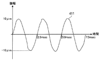
- FIG. 4 is a waveform diagram showing an example of a vibration waveform of the touch panel 220.
- the vertical axis represents amplitude [ ⁇ m]
- the horizontal axis represents time [msec].
- the touch panel 220 vibrates with a sine wave 411 having an amplitude of 10 ⁇ m and a period of 2.5 msec (that is, a frequency of 400 Hz), for example.
- the touch panel 220 generates a panel vibration sound of 400 Hz that is the same frequency as the vibration frequency.
- a panel vibration sound is a sound in a human audible range, and as described above, there is a possibility of giving an unpleasant feeling to the operator and surrounding people.
- electronic device 100 sets the frequency of the panel vibration so that the panel vibration sound and the sound of the dominant frequency of the apparatus vibration sound form a consonant sound.
- the dominant frequency is a frequency of sound that is recognized as a main component of the sound by a person who has heard the vibration sound of the device as described above, and is a frequency that matches the vibration frequency of the vibration device.
- frequency table a table in which the rotation frequency corresponding to each operation mode of the rotary fan 270 is described.
- FIG. 5 is a diagram illustrating an example of a frequency table.
- the frequency table 430 describes the rotation frequency 432 in association with the operation mode 431.
- a rotation frequency 432 of “100 Hz” is described in association with the operation mode 431 of “high-speed rotation mode”. This indicates that when operating in the high-speed rotation mode, the dominant frequency of the device vibration sound is 100 Hz, and it is highly likely that 100 Hz sound is recognized as the main component of the device vibration sound.
- the dominant frequency acquisition unit 320 can acquire the dominant frequency based on the operation mode even when the rotation frequency control unit 280 is not notified of the value of the rotation frequency.
- a consonant is a perfect 1 degree frequency ratio, a short 3 degree frequency ratio, a long 3 degree frequency ratio, a perfect 4 degree frequency ratio, a perfect 5 degree, and a perfect 8 degree frequency ratio.
- a combination of multiple sounds is even when the sound constituting the Kyowa sound is replaced with a sound of N octave difference (N is a natural number) (N octave (s) higher or lower sounds), the Kyowa sound is formed. That is, the frequency ratio obtained by multiplying or dividing the above-mentioned frequency ratio by an integer power of 2 is also the frequency ratio of the two sounds that make up the consonant sound.
- a consonant is a frequency ratio equal to the quotient of two natural numbers of 6 or less, a frequency ratio obtained by multiplying the frequency ratio by an integer power of 2, and a quotient of two natural numbers of 6 or less.
- each of these consonants has a unique tolerance.
- the consonance is a combination of a plurality of sounds that satisfy the permissible range among the above-mentioned consonances.
- the frequency of this sound constitutes the frequency ratio of the consonant sound.
- the “frequency ratio of the consonance” means a frequency ratio that is regarded as a pitch that is consonated when the frequency ratio is replaced with a pitch of equal temperament, that is, a range of frequency ratio that is acceptable to the listener as a consonant. .
- the piano is not well tuned, and when you press the “do” key on the piano, it may be heard as a different pitch. For example, it may be heard as a sound of “Do #”, “Le”, “Shi”, “Shi”. Such a deviation is outside the allowable range.
- Non-Patent Document 1 Since the relationship between the frequency ratio and the allowable range in such a consonant is well known to those skilled in acoustics (see, for example, Non-Patent Document 1), a detailed description thereof is omitted here.
- the “frequency ratio of the consonance” in the present embodiment is not limited to one octave as described above, but includes all arbitrary consonances in musical instrument acoustics and their allowable ranges.
- the harmonies reduce the discomfort given to the listener compared to the individual sounds that make up the harmonies. Furthermore, the consonance can give comfort to the listener as compared to the case of silence. In addition, when including sounds with different octaves in the vibration frequency candidates of the touch panel 220, the consonant sound can be obtained from a wide range of bands. However, it is usually better for the listener that the vibration frequency candidates are within one octave. The comfort given is high.
- the consonance determination unit 330 shown in FIG. 2 calculates the above consonant frequencies based on a consonance frequency ratio list describing frequency ratios that can form the above consonants (hereinafter referred to as “consonance frequency ratios”). judge.
- the consonance determination unit 330 stores a consonance frequency ratio list in advance.
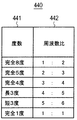
- FIG. 6 is a diagram illustrating an example of a Kyowa frequency ratio list.
- the consonant frequency ratio list 440 is a list of ratios of frequencies of two sounds when two sounds form a consonant. As shown in FIG. 6, the consonant frequency ratio list 440 describes a frequency ratio 442 corresponding to the frequency 441 for each frequency 441 of the consonance as an item of the list. The description of the frequency 441 is not necessarily required in the consonant frequency ratio list 440.
- the consonant frequency ratio list 440 describes at least one frequency ratio different from the harmonic frequency ratio among the two sound ratios constituting the consonant.
- the frequency ratio which makes a harmonic is frequency ratio 1: n (n is an integer power of 2).
- the frequency ratio 442 may be described in an integer ratio format as shown in FIG. 6, or may be described in another format such as a decimal format or a fraction format.
- consonant frequency ratio list 440 is referred to, and the above-mentioned consonant frequency is easily and quickly performed by performing the calculation for each frequency 441 by multiplying the dominant frequency by the consonant frequency ratio 442. Can be determined.
- the consonant determination unit 330 may obtain the frequency of the determined octave difference of the consonant by multiplying the frequency of the consonant by the Nth power of 2 or may be obtained by an N-bit left shift operation. .
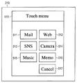
- FIG. 7 is a plan view showing an example of an image displayed on the display 210.
- a menu 510 is displayed on the display 210.
- the menu screen 510 includes a first operation button 511 described as “Mail”, a second operation button 512 described as “Web”, and a third operation button 513 described as “SNS”. Yes.
- the menu screen 510 includes a fourth operation button 514 described as “Camera”, a fifth operation button 515 described as “Music”, a sixth operation button 516 described as “Memo”, and A seventh operation button 517 described as “Cancel” is provided.
- the operator touches (presses down) an area corresponding to an arbitrary button of the first to seventh operation buttons 511 to 517 on the touch panel 220, thereby pressing the arbitrary button. Can be touched.
- the operator touches the first operation button 511 when starting the mail application, and presses the second operation button when starting the web application.
- Each button is associated with a process having a different purpose, but the description is omitted here.
- FIG. 8 is a diagram showing an example of coordinate range information generated corresponding to the display image shown in FIG. As described above, the coordinate range information is information generated by the display control unit 240 and information indicating the display position of each button.
- the coordinate range information 520 is associated with the region identifier 521 and includes a minimum value 522 of the X coordinate, a minimum value 523 of the Y coordinate, a maximum value 524 of the X coordinate, and a maximum value 525 of the Y coordinate. It is described.
- the area identifier 521 is information for identifying an operation component (here, the first to sixth operation buttons 511 to 516) displayed on the display 210. Values 522 to 525 indicating coordinate values indicate the coordinate range on the display 210 of the area where the operation component is displayed.
- the method of describing the coordinate range in the coordinate range information 520 is not limited to the above example.
- the coordinate range of the circular operation button can be described by the X and Y coordinates and the radius of the center point.
- the operation button coordinate range having a more complicated shape can be described by a data structure representing a curve connecting a plurality of points.
- the coordinate range may include a Z coordinate. As a result, for example, it can be used as a condition for determining that the finger has been pressed when the X coordinate and the Y coordinate are within a predetermined range and the finger pressure exceeds a predetermined value.
- FIG. 9 is a diagram illustrating an example of vibration necessity information.
- the vibration necessity information is information generated by the display control unit 240 and is information indicating whether or not each button is a vibration button.
- the vibration necessity information 530 describes the vibration necessity 532 in association with the area identifier 531 (corresponding to the area identifier 521 in FIG. 8).
- the necessity for vibration 532 indicates whether or not the button is a vibration required button.
- the vibration necessity 532 of “YES” is described in association with the area identifier 531 of the first to sixth operation buttons 511 to 516.
- a vibration necessity 532 of “NO” is described in association with the area identifier 531 of the seventh operation button 517. This indicates that the first to sixth operation buttons 511 to 516 are vibration-required buttons and the seventh operation button 517 is not a vibration-required button.
- the frequency range setting unit 310 sets a frequency range and a frequency default value for each of the operation buttons based on the coordinate range information 520 and the vibration necessity information 530. Then, the frequency range setting unit 310 notifies the vibration frequency setting unit 340 of the frequency information for each region indicating the setting content.
- FIG. 10 is a diagram illustrating an example of frequency information for each region.
- the frequency information for each region is information generated by the frequency range setting unit 310 as described above, and is information indicating the frequency range and frequency default value of each vibration button.
- the frequency information 540 for each region describes a frequency default value 542 and an allowable error range 543 in association with the region identifier 541 (corresponding to the region identifier 521 in FIG. 8).
- a range obtained by applying the error allowable range 543 to the frequency default value 542 is the above-described frequency range.
- a frequency default value 542 of “140 Hz” and an error allowable range 543 of “ ⁇ 15%” are described in association with the area identifier 541 of the first operation button 511. This indicates that the frequency range is 119 Hz to 161 Hz.
- the frequency default value 542 indicates that it is the median value of the frequency range.
- a frequency default value 542 of “0 Hz” and an error allowable range 543 of “0%” are described in association with the area identifier 541 of the seventh operation button 517. This indicates that the frequency default value and frequency range are not set substantially. This is because the seventh operation button 517 is not a vibration required button.
- Such frequency information 540 by region, the above-described coordinate range information 520 (see FIG. 8), and vibration necessity information 530 (see FIG. 9) are stored in the vibration control device 300. Thereby, when a touch operation is performed on any of the operation buttons, the vibration control device 300 can quickly and easily identify the frequency range corresponding to the operation button.
- the description method of the frequency range and the frequency default value in the frequency information 540 by region is not limited to the above example.
- the frequency range and the frequency default value can be described by the minimum value and the maximum value of the frequency range and the fact that the frequency default value is the median value of the frequency range.
- the vibration control device 300 starts an operation described below every time operation target information about a new image is input from the display control unit 240, for example.
- the menu 510 (FIG. 7) is displayed on the display 210.
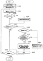
- FIG. 11 is a flowchart showing an example of the operation of the vibration control device.
- the frequency range setting unit 310 sets a frequency default value and a frequency range for each operation content corresponding to the operation button, for example.
- the frequency range setting unit 310 performs such setting based on the operation target information input from the display control unit 240.
- the operation target information is generated for each display image, and includes coordinate range information 520 and vibration necessity information 530 (see FIGS. 8 and 9).
- the dominant frequency acquisition unit 320 acquires the operation mode notified from the rotation speed control unit 280.
- the acquisition of this operation mode may be performed by regular notification from the rotation speed control unit 280 or may be performed by an inquiry from the dominant frequency acquisition unit 320.
- the dominant frequency acquisition unit 320 determines whether or not the vibration operation is performed in the vibration source from the acquired operation mode. Specifically, the dominant frequency acquisition unit 320 determines whether the acquired operation mode is a high-speed rotation mode, a low-speed rotation mode, or a rotation stop mode.
- the dominant frequency acquisition unit 320 proceeds to step S1400.
- the dominant frequency acquisition unit 320 proceeds to step S1500 described later.
- the dominant frequency acquisition unit 320 may perform the processing of steps S1200 to S1400 only when the processing is started and when the operation mode is switched.
- step S1400 the dominant frequency acquisition unit 320 performs a dominant frequency acquisition process.
- the dominant frequency acquisition process is a process for acquiring the dominant frequency of the apparatus vibration sound. The dominant frequency acquisition process will be described later.
- step S1500 the vibration frequency setting unit 340 determines whether or not an operation requiring feedback due to vibration during operation (hereinafter referred to as “vibration requiring operation”) has been performed.
- the vibration frequency setting unit 340 includes operation position information from the touch panel detection unit 250, coordinate range information 520 (see FIG. 8) and vibration necessity information 530 (see FIG. 9) from the display control unit 240. This determination is made based on the above.
- the vibration frequency setting unit 340 determines whether or not the position of the touch operation is included in the coordinate range of any of the operation buttons. If included, the vibration operation is performed on the corresponding operation button. to decide. Then, the vibration frequency setting unit 340 determines whether or not the operation button on which the corresponding touch operation is performed is a vibration required button.
- the vibration frequency setting unit 340 proceeds to step S1600 when a vibration requiring operation is performed (S1500: YES). Moreover, the vibration frequency setting part 340 progresses to below-mentioned step S2100, when vibration required operation is not performed (S1500: NO).
- step S1600 the vibration frequency setting unit 340 determines whether a vibration operation is performed in the vibration operation unit.
- the vibration frequency setting unit 340 can determine whether or not a vibration operation is being performed based on, for example, whether or not a vibration frequency candidate group has been notified. In addition, when the dominant frequency acquisition unit 320 generates a flag indicating the presence or absence of the dominant frequency, the vibration frequency setting unit 340 can determine from this flag whether or not a vibration operation is being performed.
- the vibration frequency setting unit 340 proceeds to step S1700 when the vibration operation is performed (S1600: YES). Further, when the vibration operation is not performed (S1600: NO), the vibration frequency setting unit 340 proceeds to step S1900 described later.
- step S1700 the vibration frequency setting unit 340 determines whether any vibration frequency candidate is included in the frequency range set for the operation content of the performed operation.
- the vibration frequency setting unit 340 obtains the frequency range and the frequency default value for the operation button on which the touch operation has been performed, from the frequency information 540 for each region notified from the frequency range setting unit 310 (see FIG. 10). get.
- the vibration frequency setting unit 340 includes a plurality of vibration frequency candidates described in the vibration frequency candidate group 460 (see FIG. 14) notified from the consonance determination unit 330 and included in the acquired frequency range. Determine if it exists.
- the vibration frequency setting unit 340 proceeds to step S1800 when at least one vibration frequency candidate is included in the frequency range (S1700: YES). If none of the vibration frequency candidates is included in the frequency range (S1700: NO), vibration frequency setting unit 340 proceeds to step S1900 described later.
- vibration frequency setting unit 340 determines the vibration frequency candidate as the vibration frequency of touch panel 220. Further, when there are a plurality of vibration frequency candidates included in the frequency range, the vibration frequency setting unit 340 determines a vibration frequency candidate closer to the frequency default value as the vibration frequency of the touch panel 220.
- the vibration frequency of the touch panel 220 may change within a set frequency range due to a change in the dominant frequency (that is, a change in the operation mode). By determining the vibration frequency candidate closer to the frequency default value, a large change in the vibration frequency of the operation button can be avoided as much as possible, and the uncomfortable feeling given to the operator can be reduced.
- the vibration frequency setting unit 340 determines the frequency default value as the vibration frequency of the touch panel 220. This is because there is no harmony in the frequency range set for the operation button on which the vibration operation is not performed or the touch operation is performed.
- the vibration frequency setting unit 340 determines 800 Hz that is the frequency default value set in the fifth operation button 515 as the vibration frequency of the touch panel 220.
- the vibration frequency setting unit 340 may prioritize vibration at a frequency that becomes a consonant sound, rather than vibrating the touch panel 220 within the frequency range set for the operation button. In this case, for example, the vibration frequency setting unit 340 may ignore the frequency range and determine the consonance closest to the frequency default value as the vibration frequency of the touch panel 220.
- step S2000 the vibration frequency setting unit 340 causes the touch panel 220 to vibrate at the determined vibration frequency. Specifically, the vibration frequency setting unit 340 generates a vibration instruction signal instructing to vibrate the vibration element 230 for a predetermined time with the determined vibration frequency. Then, the vibration frequency setting unit 340 outputs the generated vibration instruction signal to the vibration element control unit 260.
- step S2100 the dominant frequency acquisition unit 320 determines whether it is time to end the processing for the same display screen.
- the process for the same display screen is a process for determining the vibration frequency using the frequency information 540 for each region (see FIG. 10) generated in step S1100 as it is.
- the superior frequency acquisition unit 320 returns to step S1200 when it is not time to end the process for the same display screen, such as when the same display screen is maintained (S2100: NO).
- the dominant frequency acquisition unit 320 ends a series of processes when it is the timing to end the process for the same display screen, such as the timing at which the display screen is switched or the timing at which the screen display ends (S2100: YES). To do. Note that when the display screen is switched to another screen that accepts a touch operation, the vibration control device 300 starts processing from step S1100.
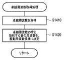
- FIG. 12 is a flowchart illustrating an example of the dominant frequency acquisition process.
- the dominant frequency acquisition unit 320 acquires the rotational frequency of the rotary fan 270 as the dominant frequency.
- the dominant frequency acquisition unit 320 refers to the frequency table 430 (see FIG. 5), and acquires the rotation frequency corresponding to the acquired operation mode as the dominant frequency.
- step S1420 the consonance determination unit 330 determines the frequency of the sound that cooperates with the sound of the dominant frequency as a vibration frequency candidate (hereinafter referred to as “vibration frequency candidate”) of the touch panel 220, and performs the processing of FIG. Return to.
- vibration frequency candidate a vibration frequency candidate
- FIG. 13 is a diagram illustrating an example of a frequency spectrum of the apparatus vibration sound.
- the horizontal axis indicates the frequency [Hz]
- the vertical axis indicates the sound pressure level (sound intensity) [dB].
- the operation mode is the high-speed rotation mode (rotation frequency 100 Hz) is shown.
- the frequency spectrum curve 551 of the apparatus vibration sound has a sound pressure level predominant (outstanding) near 100 Hz. , 65 dB. Such a sound with a sound pressure level that is prominent compared to other frequencies (excellent sound) is easily heard by humans.
- the consonance determination unit 330 multiplies each frequency ratio 442 described in the consonance frequency ratio list shown in FIG. 6 and the reciprocal of each frequency ratio 442 by the dominant frequency. Then, the consonant sound determination unit 330 determines the calculation result as a vibration frequency candidate group, and notifies the vibration frequency setting unit 340 of the determination result.
- FIG. 14 is a diagram illustrating an example of a vibration frequency candidate group. Here, an example in which 100 Hz is extracted as the dominant frequency is shown.
- the vibration frequency candidate group 460 includes, for example, “50.0 Hz”. This is the result of multiplying 100 Hz by a complete frequency ratio of 1/2 to 8 degrees.
- the vibration frequency candidate group 460 includes, for example, “20.0 Hz”. This is a result of multiplying 100 Hz by 2, which is the reciprocal of the frequency ratio 1/2 of 8 degrees.
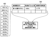
- FIG. 15 is a diagram illustrating an example of how the vibration frequency is determined. Here, a case where a touch operation is performed on the first operation button 511 (see FIG. 7) is shown.
- the frequency range set for the first operation button 511 is within a range of ⁇ 15% of 140 Hz, that is, a range of 119 Hz to 161 Hz. is there.
- the vibration frequency candidate group 460 there are five vibration frequency candidates included in the frequency range. Of these five vibration frequency candidates, “133.3 Hz” is the closest to the frequency default value of 140 Hz.
- the vibration frequency setting unit 340 determines 133.3 Hz as the vibration frequency of the touch panel 220.
- various information described as being notified to other device units may be indirectly exchanged by being stored in a memory that can be referred to from the other device units.
- Good various types of information described as being stored in a memory that can be referred to from another device unit may be directly notified to the other device unit.
- the electronic device 100 obtains the dominant frequency of the device vibration sound in the vibration control device 300 so that the panel vibration sound becomes a sound that synchronizes with the sound of the dominant frequency. Set the frequency of panel vibration during touch operation.
- electronic device 100 according to the present embodiment keeps the vibration frequency of touch panel 220 in a band where a feeling of operation of touch operation can be sufficiently obtained, and annoying discomfort (annoying) due to panel vibration sound. discomfort) can be reduced.
- the electronic device 100 according to the present embodiment does not need to separately generate high frequency sound. That is, in the use of the touch panel that vibrates in synchronization with the touch operation, electronic device 100 according to the present embodiment achieves both reduction in discomfort due to panel vibration sound and maintenance of the operational feeling of touch operation on touch panel. Can do.
- the present invention in the second embodiment of the present invention, the example in which the present invention is applied to the electronic device 100 including the rotation fan 270 and the rotation speed control unit 280 as the vibration source has been described.
- the application of the present invention is limited to this.
- the present invention can be applied to an electronic device including a compressor and a control unit that controls the number of rotations as a vibration source.
- the present invention can also be applied to an electronic device including a device for generating sound, such as a speaker, and a control unit that controls the pitch as a vibration source.
- This embodiment can also be applied to the case where there are a plurality of vibration sources, and the sounds having the dominant frequencies generated by the plurality of vibration sources are in a cooperative relationship.
- the vibration control device sets the frequency of the sound to the harmony frequency.
- the vibration control device obtains a consonant frequency candidate group for one dominant frequency, and further performs a process of narrowing down the consonant frequency candidate group for the next dominant frequency from the obtained candidate group. Just do it.
- the vibration control device obtains a consonant frequency candidate group for each dominant frequency and, from the obtained consonant frequency candidate group, obtains a consonant frequency candidate that falls within a predetermined error for all the dominant frequencies. What is necessary is just to set to sound frequency. Further, in these processes, the vibration control device prioritizes the sound that cooperates with the dominant frequency that is easily audible to the human ear based on the sound pressure level and frequency band of the dominant sound, and narrows down the consonant frequency candidates. You may do it.
- a vibration control device of the present disclosure is a vibration control device that is used for an electronic device including a touch panel that vibrates in synchronization with a touch operation and a vibration source that is different from the touch panel, and the vibration frequency of the vibration source And a predominance frequency acquisition unit that uses the acquired vibration frequency as the prevailing frequency of the vibration of the vibration source, and a consonance determination unit that determines the consonant frequency that is the frequency of the sound that co-harmonizes with the sound of the acquired prevailing frequency And a vibration frequency setting unit that sets the vibration frequency of the touch panel to the determined harmony frequency.
- the vibration source operates by switching a plurality of operation modes that vibrate at different predetermined frequencies, and the dominant frequency acquisition unit is configured so that the vibration source is in any one of the plurality of operation modes.
- the frequency corresponding to the determined operation mode may be acquired as the vibration frequency of the vibration source.
- the vibration control device may further include a vibration sensor that detects vibration of the electronic device, and the dominant frequency acquisition unit may acquire the vibration frequency of the vibration source from the vibration data of the vibration sensor.
- the vibration source may include a rotation motor
- the dominant frequency acquisition unit may set the rotation frequency of the rotation motor as the dominant frequency
- the vibration frequency setting unit determines whether or not the consonant frequency is included in a preset frequency range, and when the consonant frequency is included in the frequency range, the touch panel If the frequency of vibration is set to a consonant frequency and the consonant frequency is not included in the frequency range, the frequency of the vibration is included in the frequency range and is a preset value. It may be set to a default value.
- the frequency range may be a frequency range in which a touch operation feeling can be obtained when the frequency of the vibration of the touch panel is set within the frequency range.
- the dominant frequency acquisition unit determines whether or not the vibration source is operating, and the vibration frequency setting unit sets the vibration frequency to a frequency default value when the vibration source is not operating. It may be set.
- the consonance determination unit may determine, as a consonance frequency, a value obtained by multiplying the acquired dominant frequency by a frequency ratio between two sounds constituting the consonance. Good.
- the frequency ratio between the two sounds constituting the Kyowa sound is a perfect 1 degree frequency ratio, a short 3 degree frequency ratio, a long 3 degree frequency ratio, and a perfect 4 degree frequency ratio. Obtained by multiplying each of these frequency ratios by an integer power of 2, or dividing each of these frequency ratios by an integer power of 2. At least one of the frequency ratios may be included.
- the vibration control apparatus further includes a frequency range setting unit that acquires operation contents that can be input by a touch operation, and sets a frequency range and a frequency default value for the acquired operation contents.
- the unit may set different frequency ranges and different frequency default values for a plurality of operation contents.
- the electronic device of the present disclosure acquires and acquires a touch panel that accepts a touch operation, a vibration generation unit that generates vibration in the touch panel in synchronization with the touch operation, a vibration source that is different from the touch panel, and a vibration frequency of the vibration source.
- a vibration frequency that is the dominant frequency of the vibration source a consonant frequency determination unit that determines a consonant frequency that is a frequency of sound that cooperates with the acquired sound of the dominant frequency, and a vibration frequency
- a vibration frequency setting unit that sets the determined harmony frequency.
- a vibration control method of the present disclosure is a vibration control method used for an electronic device including a touch panel that vibrates in synchronization with a touch operation and a vibration source different from the touch panel, and the vibration frequency of the vibration source And acquiring the acquired vibration frequency as a dominant frequency of the vibration of the vibration source, determining a consonant frequency that is a frequency of the sound that cooperates with the acquired sound of the dominant frequency, and Setting the frequency to the determined consonant frequency.
- the present invention relates to a vibration control device, an electronic device, and a vibration capable of reducing both discomfort caused by panel vibration sound and maintaining the operational feeling of touch operation in the use of a touch panel that vibrates in synchronization with the touch operation. It is useful as a control method.
- the present invention is, for example, a smartphone, a tablet terminal, a car navigation, a refrigerator, a microwave oven, a copy machine, an electric massager, an electric toothbrush, etc. It is suitable for an electronic device that emits a rotating sound at a certain frequency, such as a refrigerator or an air conditioner.
Landscapes
- Engineering & Computer Science (AREA)
- General Engineering & Computer Science (AREA)
- Theoretical Computer Science (AREA)
- Human Computer Interaction (AREA)
- Physics & Mathematics (AREA)
- General Physics & Mathematics (AREA)
- User Interface Of Digital Computer (AREA)
- Position Input By Displaying (AREA)
Abstract
タッチ操作に同期して振動するタッチパネルの使用において、パネル振動音による不快感の低減と、タッチパネルのタッチ操作の操作感の維持とを両立させる。振動制御装置(300)は、タッチ操作に同期して振動するタッチパネルと、タッチパネルとは別の振動源と、を備えた電子機器に対して用いられる装置であって、振動源の振動周波数を取得し、取得した振動周波数を、振動源の振動の卓越周波数とする卓越周波数取得部(320)と、取得された卓越周波数の音と協和する音の周波数である協和音周波数を判定する協和音判定部(330)と、タッチパネルの振動の周波数を、判定された協和音周波数に設定する振動周波数設定部(340)と、を有する。
Description
本発明は、タッチ操作に同期して振動するタッチパネルに対して用いられる、振動制御装置および振動制御方法に関する。
近年、スマートフォンやタブレット端末あるいは家電製品等、入力インタフェースとしてタッチパネルを備えた各種の電子機器において、タッチ操作に同期してタッチパネルを振動させることが広く行われている(例えば特許文献1参照)。このようなタッチパネルの振動は、タッチ操作に触覚によるフィードバックを付与し、従来のキースイッチ操作において得られていた操作感(operational feeling)(例えば、クリック感(click feeling)、タクタイル感(tactile feeling))を補完することができる。
ところが、タッチパネルの振動(以下、適宜「パネル振動」という)は、電子機器の他の部分や、電子機器が置かれた机等に伝搬し、振動音を発生させることがある。このような、パネル振動により発生する振動音(以下、適宜「パネル振動音」(panel vibration sound)という)の周波数は、通常、パネル振動の周波数に一致する。本来、パネル振動音は、不要な音であり、操作者や周囲の人に不快感を与え得る。
そこで、人の耳に伝わり難い周波数でパネル振動を行う技術が、例えば特許文献2に記載されている。また、高周波数の音を別途発生させることにより、パネル振動音を聞こえ難くする技術が、例えば特許文献3に記載されている。これらの従来技術は、パネル振動音による不快感を低減することができる。
梅本堯夫、「音楽心理学」、誠信書房、第2章§3「協和に関する実験的知見」、1966年6月28日
しかしながら、従来技術は、パネル振動音による不快感の低減と、タッチパネルのタッチ操作の操作感の維持とを両立させることが難しいという課題を有する。
理由は、以下の通りである。人の耳の可聴域は、通常、20~2万Hzである。一方、電子機器の他の機能に悪影響を及ぼさない範囲で、タッチ操作の操作感が十分に得られるような振動の帯域は、通常、50Hz~400Hz付近(特許文献3参照)である。すなわち、操作感が得られるパネル振動の周波数の大部分は、人の耳の可聴域と重複している。また、操作感を得るためには、ある程度の振動強度が必要であるが、その分、高周波数の音の音量を大きくする必要がある。すなわち、高周波数の音を別途発生させることは、操作者や周囲の人に与える不快感を増大させるおそれがある。
また、回転ファンやコンプレッサなど、タッチパネルとは別の振動源(vibrating source)を備えた電子機器では、かかる振動に起因した音(以下「装置振動音」(apparatus vibration sound)という)が発生することが多い。したがって、特にこのような電子機器では、パネル振動音と装置振動音とが混ざり合い、上記不快感を更に増大させ得る。
本発明の目的は、タッチ操作に同期して振動するタッチパネルの使用において、パネル振動音による不快感の低減と、タッチ操作の操作感の維持とを両立させることである。
本発明の一態様に係る振動制御装置は、タッチ操作に同期して振動するタッチパネルと、タッチパネルとは別の振動源と、を備えた電子機器に対して用いられる振動制御装置であって、振動源の振動周波数(vibrational frequency)を取得し、取得した振動周波数を、振動源の振動の卓越周波数(predominant frequency)とする卓越周波数取得部(predominant frequency acquiring section)と、取得された卓越周波数の音と協和する(in consonant with)音の周波数である協和音周波数(consonant sound frequency)を判定する協和音判定部(consonant sound determining section)と、タッチパネルの振動の周波数を、判定された協和音周波数に設定する振動周波数設定部(vibrational frequency setting section)と、を有する。
本発明の一態様に係る電子機器は、タッチ操作を受け付けるタッチパネルと、タッチ操作に同期してタッチパネルに振動を発生させる振動発生部と、タッチパネルとは別の振動源と、振動源の振動周波数を取得し、取得した振動周波数を、振動源の振動の卓越周波数とする卓越周波数取得部と、取得された卓越周波数の音と協和する音の周波数である協和音周波数を判定する協和音判定部と、タッチパネルの振動の周波数を、判定された協和音周波数に設定する振動周波数設定部と、を有する。
本発明の一態様に係る振動制御方法は、タッチ操作に同期して振動するタッチパネルと、タッチパネルとは別の振動源と、を備えた電子機器に対して用いられる振動制御方法であって、振動源の振動周波数を取得し、取得した振動周波数を、振動源の振動の卓越周波数とするステップと、取得された卓越周波数の音と協和する音の周波数である協和音周波数を判定するステップと、タッチパネルの振動の周波数を、判定された協和音周波数に設定するステップと、を有する。
本発明は、タッチ操作に同期して振動するタッチパネルの使用において、パネル振動音による不快感の低減と、タッチ操作の操作感の維持とを両立させることができる。
以下、本発明の各実施の形態について、図面を参照して詳細に説明する。
(実施の形態1)
本発明の実施の形態1は、本発明の基本的態様の一例である。
本発明の実施の形態1は、本発明の基本的態様の一例である。
図1は、本実施の形態に係る振動制御装置の構成の一例を示すブロック図である。
図1に示す振動制御装置300は、タッチ操作に同期して振動するタッチパネルと、タッチパネルとは別の振動源と、を備えた電子機器に対して用いられる装置である。図1において、振動制御装置300は、卓越周波数取得部(predominant frequency acquiring section)320、協和音判定部(consonant sound judging section)330、および振動周波数設定部(vibrational frequency setting section)340を有する。
卓越周波数取得部320は、振動源の振動周波数を取得し、取得した振動周波数を、振動源の振動の卓越周波数とする。なお、振動の卓越周波数とは、当該振動に起因して発生した音を聞いた人に、当該音の主成分として認識される音の周波数である。
協和音判定部330は、取得された卓越周波数(predominant frequency)の音と協和する音の周波数である協和音周波数(consonant sound frequency)を判定する。
振動周波数設定部340は、タッチパネルの振動の周波数を、判定された協和音周波数に設定する。
振動制御装置300は、図示しないが、例えば、CPU(central processing unit)、制御プログラムおよび各種データを格納したROM(read only memory)等の記憶媒体、およびRAM(random access memory)等の作業用メモリを有する。この場合、上記した各部の機能は、CPUが制御プログラムを実行することにより実現される。
協和音(consonant sound)は、協和音を構成する個々の音のみに比べて、聞く人に与える不快感を低減する。したがって、パネル振動音が別の音と協和する(in consonant with)関係にあれば、パネル振動音が操作者や周囲の人に与える不快感は、低減される。また、協和音は、無音の場合に比べて、聞く人に対して心地良さを与え得る。
一方で、振動源を備えた電子機器では、装置振動音が発生することがある。
そこで、本実施の形態に係る振動制御装置300は、上述の通り、装置振動音の卓越周波数を取得し、パネル振動音が卓越周波数の音と協和する音となるように、パネル振動の周波数を設定する。
これにより、本実施の形態に係る振動制御装置300は、パネル振動の周波数を可聴域に留めたままで、かつ、他の高周波数の音を出力することなく、パネル振動音が人に与える不快感を低減することができる。すなわち、本実施の形態に係る振動制御装置300は、タッチ操作に同期して振動するタッチパネルの使用において、パネル振動音による不快感の低減と、タッチ操作の操作感の維持とを両立させることができる。
また、本実施の形態に係る振動制御装置300は、上述の特許文献2に記載の技術に比べて、パネル振動に用いることができる周波数帯域の範囲を広げることができる。つまり、本実施の形態に係る振動制御装置300は、パネル振動に用いることができる周波数帯域の範囲が広いほど、操作者に対して伝えることができる触覚の種類の範囲も広くなる。したがって、本実施の形態に係る振動制御装置300は、例えば、複数の操作内容に対して、操作者が違いを認識することが可能な異なる周波数の振動を設定することが可能となる。
また、本実施の形態に係る振動制御装置300は、高周波数の音を別途出力する必要がないため、上述の特許文献3に記載の技術に比べて、消費電力の増大を抑えることができる。
(実施の形態2)
本発明の実施の形態2は、本発明を電子機器に適用した場合の、本発明の具体的態様の一例である。
本発明の実施の形態2は、本発明を電子機器に適用した場合の、本発明の具体的態様の一例である。
<電子機器の構成>
図2は、本実施の形態に係る振動制御装置を含む電子機器の構成の一例を示すブロック図である。
図2は、本実施の形態に係る振動制御装置を含む電子機器の構成の一例を示すブロック図である。
図2において、電子機器100は、ディスプレイ210、タッチパネル220、振動素子230、ディスプレイ制御部240、タッチパネル検出部250、振動素子制御部260、回転ファン270、回転数制御部280、および振動制御装置300を有する。
ディスプレイ210は、後述のディスプレイ制御部240から入力される画像データに基づいて、画像を表示する。ディスプレイ210の具体例としては、LCD(Liquid Crystal Display)、有機EL(Electro Luminescence)ディスプレイ、およびLED(Light Emitting Diode)ディスプレイ等が挙げられる。
タッチパネル220は、ディスプレイ210の表面に配置され、タッチ操作(押下入力(press down input))を受け付ける。そして、タッチパネル220は、タッチ操作が行われる毎に、タッチ操作の位置を示す操作信号を、後述のタッチパネル検出部250へ出力する。操作信号は、例えば、タッチパネル220のX軸の電圧値およびY軸の電圧値を示す信号である。タッチパネル220の具体例としては、フィルムとプラスチックで構成される抵抗膜方式のタッチパネル等が挙げられる。
振動素子230は、ディスプレイ210の裏面に配置され、後述の振動素子制御部260から入力される振動制御信号に基づいて、振動を発生させる。振動素子230が発生させる振動の周波数は、少なくとも後述の周波数範囲において、可変であるものとする。振動素子230の具体例としては、ピエゾ・アクチュエータ方式の振動素子、リニア共振アクチュエータ(LRA: Linear Resonant Actuator)方式の振動素子、およびバイブレータ等が挙げられる。
ディスプレイ制御部240は、ディスプレイ210に表示される画像の表示制御を行う。具体的には、ディスプレイ制御部240は、ディスプレイ210に表示されるべき画像の画像データを生成し、生成した画像データを、ディスプレイ210へ出力する。また、ディスプレイ制御部240は、上記画像においてタッチ操作により入力可能な操作内容を示す操作対象情報を、振動制御装置300へ出力する。
本実施の形態において、ディスプレイ制御部240は、複数のボタンが配置された画像を、ディスプレイ210に表示させる。そして、ディスプレイ210は、上記操作対象情報として、座標範囲情報および振動要否情報を、振動制御装置300へ出力する。座標範囲情報は、各ボタンのディスプレイ制御部240において表示される位置(以下「表示位置」という)を示す情報である。振動要否情報は、各ボタンが操作時に振動によるフィードバックを要するボタン(以下「要振動ボタン」という)であるか否かを示す情報である。
なお、振動制御装置300は、入力された座標範囲情報および振動要否情報を、振動制御装置300の各部から参照可能なメモリに格納する。
タッチパネル検出部250は、タッチパネル220から入力される操作信号に基づいて、タッチパネル220に対して行われたタッチ操作(以下、単に「タッチ操作」という)の、タッチパネル220における位置の検出を行う。例えば、タッチパネル検出部250は、操作信号をデジタル値へと変換し、タッチパネル220におけるX座標とY座標を得る。
なお、本実施の形態において、タッチパネル220上の位置とディスプレイ210上の位置との対応関係は、予めタッチパネル検出部250に設定されている。タッチパネル検出部250は、この対応関係に基づいて、タッチ操作のディスプレイ210における位置を検出する。そして、タッチパネル検出部250は、タッチ操作のディスプレイ210における位置を示す情報(以下「操作位置情報」という)を、振動制御装置300へ出力する。
振動素子制御部260は、後述の振動制御装置300から入力される振動指示信号に基づいて、タッチ操作に同期して振動素子230を振動させる。すなわち、振動素子制御部260は、上述の振動素子230と共に本発明の振動発生部を構成し、タッチ操作に同期してタッチパネル220に振動を発生させる。また、振動素子制御部260は、上記振動指示信号に基づいて、当該振動の周波数を制御する。
回転ファン270は、例えば、後述のCPUを冷却するためのファンであり、後述の回転数制御部280から入力される回転制御信号に基づいて、回転する。なお、回転ファン270は、回転する際に、回転周波数と等しい周波数で、回転音を発生させるものとする。また、回転ファン270は、インバータ方式の回転モータにより駆動される。すなわち、回転ファン270の回転周波数(つまりモータの回転周波数)は、可変であるものとする。
回転数制御部280は、例えば、CPU周辺の温度やCPUの稼働状態に応じて、回転ファン270の回転数(あるいは回転周波数)を制御する。本実施の形態では、回転ファン270の動作モードとして、予め定められた高い回転数で回転する高速回転モードと、予め定められた低い回転数で回転する低速回転モードと、回転しない回転停止モードとが存在するものとする。
すなわち、回転数制御部280は、回転ファン270と共に本発明の振動源を構成し、予め定められた異なる周波数で振動する複数の動作モードを切り替えて動作する。また、回転数制御部280は、現在の動作モードを示す情報を、振動制御装置300に対して通知する。なお、この際に、回転数制御部280は、当該動作モードを示す情報として、回転ファン270の回転周波数を通知してもよい。
振動制御装置300は、周波数範囲設定部310、卓越周波数取得部320、協和音判定部330、および振動周波数設定部340を有する。
周波数範囲設定部310は、タッチ操作により入力可能な操作内容を取得し、取得した操作内容に対して、周波数範囲および周波数デフォルト値を設定する。但し、周波数範囲設定部310は、複数の操作内容が存在するとき、当該複数の操作内容に対して、異なる周波数範囲および異なる周波数デフォルト値を設定する。また、周波数範囲設定部310は、電子機器の他の機能に悪影響を及ぼさない範囲で、タッチ操作の操作感が十分に得られるような振動の周波数帯域(例えば、50Hz~400Hz)から、周波数範囲を設定する。
これら周波数範囲および周波数デフォルト値は、後述の協和音判定部330により、振動素子230の振動の周波数を決定する際に用いられる。
本実施の形態において、周波数範囲設定部310は、ディスプレイ制御部240から入力された操作対象情報(座標範囲情報および振動要否情報)から、要振動ボタンの表示位置を取得する。そして、周波数範囲設定部310は、要振動ボタン毎に、周波数範囲および周波数デフォルト値を設定する。すなわち、本実施の形態において、「タッチ操作により入力可能な操作内容」とは、個々の要振動ボタンに対応する。
そして、周波数範囲設定部310は、要振動ボタン毎に設定した、周波数範囲および周波数デフォルト値を示す情報(以下「領域別周波数情報」という)を、振動制御装置300の各装置部から参照可能なメモリに格納する。
卓越周波数取得部320は、振動源が発生させる振動の卓越周波数を取得する。本実施の形態において、振動源が発生させる振動の卓越周波数は、回転ファン270の回転周波数に一致している。したがって、卓越周波数取得部320は、回転数制御部280から通知された情報に基づき、回転ファン270の回転周波数を、卓越周波数として取得する。そして、卓越周波数取得部320は、取得した卓越周波数を、協和音判定部330へ通知する。なお、電子機器100は、振動源である回転ファン270の近傍位置あるいは他の位置に、電子機器100の振動を検出する振動センサを有してもよい。この場合、卓越周波数取得部320は、この振動センサの振動データから、回転ファン270の回転周波数を取得してもよい。
協和音判定部330は、卓越周波数取得部320から通知された卓越周波数に基づいて、取得された卓越周波数の音と協和する音の周波数(以下「協和音周波数」という)を判定する。そして、協和音判定部330は、判定した協和音周波数を、振動周波数設定部340へ通知する。
振動周波数設定部340は、タッチ操作が行われる毎に、そのタッチ操作の操作内容に対して予め設定された周波数範囲および周波数デフォルト値を取得する。振動周波数設定部340は、これら周波数範囲および周波数デフォルト値の取得を、タッチパネル検出部250から入力される操作信号と、周波数範囲設定部310が生成した領域別周波数情報とに基づいて行う。
そして、振動周波数設定部340は、取得した(予め設定された)周波数範囲に、協和音判定部330から通知された協和音周波数が含まれるか否かを判断する。振動周波数設定部340は、当該周波数範囲に当該協和音周波数が含まれるとき、パネル振動の周波数を当該協和音周波数に決定する。また、振動周波数設定部340は、当該周波数範囲に当該協和音周波数が含まれないとき、パネル振動の周波数を当該周波数デフォルト値に決定する。
そして、振動周波数設定部340は、決定した周波数で振動素子230を所定時間振動させることを指示する振動指示信号を生成し、生成した振動指示信号を、振動素子制御部260へ出力する。すなわち、振動周波数設定部340は、振動素子制御部260および振動素子230を介して、タッチパネル220を、装置振動音の卓越周波数の音と協和する周波数で、タッチ操作に同期して振動させる。
電子機器100は、図示しないが、例えば、CPU、制御プログラムおよび各種データを格納したROM等の記憶媒体、およびRAM等の作業用メモリを有する。この場合、上記した各部の機能は、CPUが制御プログラムを実行することにより実現される。
このような構成を有する電子機器100は、複数のボタンを含む画面を表示し、ボタンに対するタッチ操作を受け付け、そのタッチ操作に同期して、タッチパネル220を振動させることができる。また、電子機器100は、パネル振動音が、装置振動音の卓越周波数の音と協和する音となるように、パネル振動の周波数を設定することができる。更に、電子機器100は、ボタン毎に周波数範囲および周波数デフォルト値を設定することにより、ボタン毎に異なる周波数で、パネル振動を発生させることができる。
ここで、パネル振動音、卓越周波数、および協和音について説明する。
<パネル振動音についての説明>
図3は、タッチパネル220の構成の一例を模式的に示す図である。
図3は、タッチパネル220の構成の一例を模式的に示す図である。
図3に示すように、タッチパネル220は、支持基板221と可動板222との間に、第1の駆動電極223、第2の駆動電極224、およびY印加側引き出し電極225を有する圧電素子226を配置している。可動板222には、圧電素子226毎に、Y印加側引き出し電極225に接続する第1のリード線227と、第2の駆動電極224に接続する第2のリード線228とが配線されている。
図2に示す振動素子230で発生した振動は、タッチパネル220の可動板222に伝搬し、タッチ操作を行っている人の指に伝達する。ところが、この可動板222は、その振動により、可動板222が面音源となり、上述のパネル振動音が発生する。
図4は、タッチパネル220の振動波形の一例を示す波形図である。図4において、縦軸は振幅[μm]を示し、横軸は時間[msec]を示す。
図4に示すように、タッチパネル220は、例えば、振幅10μm、周期2.5msec(つまり、周波数400Hz)の正弦波411にて、振動する。この場合、タッチパネル220は、当該振動周波数と同一の周波数である400Hzのパネル振動音を発生させる。このようなパネル振動音は、人の可聴域の音であり、上述の通り、操作者や周囲の人に対して不快感を与えるおそれがある。
そこで、本実施の形態に係る電子機器100は、上述の通り、パネル振動音と装置振動音の卓越周波数の音とが協和音を構成するように、パネル振動の周波数を設定する。
<卓越周波数についての説明>
本実施の形態において、卓越周波数とは、上述の通り、装置振動音を聞いた人に当該音の主成分として認識される音の周波数であり、振動装置の振動周波数に一致する周波数である。
本実施の形態において、卓越周波数とは、上述の通り、装置振動音を聞いた人に当該音の主成分として認識される音の周波数であり、振動装置の振動周波数に一致する周波数である。
図2に示す卓越周波数取得部320は、回転ファン270の動作モード毎に対応する回転周波数を記述したテーブル(以下「周波数テーブル」という)を予め保持していてもよい。
<周波数テーブル>
図5は、周波数テーブルの一例を示す図である。
図5は、周波数テーブルの一例を示す図である。
図5に示すように、周波数テーブル430は、動作モード431に対応付けて、回転周波数432を記述している。
周波数テーブル430には、例えば、「高速回転モード」という動作モード431に対応付けて、「100Hz」という回転周波数432が記述されている。これは、高速回転モードで動作しているとき、装置振動音の卓越周波数は100Hzであり、100Hzの音が装置振動音の主成分として認識される可能性が高いことを示す。
卓越周波数取得部320は、このような周波数テーブル430を用いることにより、回転数制御部280から回転周波数の値を通知されない場合でも、動作モードに基づいて、卓越周波数を取得することができる。
<協和音についての説明>
協和音とは、完全1度の周波数比、短3度の周波数比、長3度の周波数比、完全4度の周波数比、完全5度、および完全8度の周波数比のいずれかとなるような、複数の音の組み合わせである。また、協和音を構成する音を、Nオクターブ違い(Nは自然数)の音(N octave(s) higher or lower sounds)に入れ替えた場合でも、協和音が構成される。すなわち、上述の周波数比に2の整数乗を乗じまたは除して得られる周波数比も、協和音を構成する2つの音の周波数比である。
協和音とは、完全1度の周波数比、短3度の周波数比、長3度の周波数比、完全4度の周波数比、完全5度、および完全8度の周波数比のいずれかとなるような、複数の音の組み合わせである。また、協和音を構成する音を、Nオクターブ違い(Nは自然数)の音(N octave(s) higher or lower sounds)に入れ替えた場合でも、協和音が構成される。すなわち、上述の周波数比に2の整数乗を乗じまたは除して得られる周波数比も、協和音を構成する2つの音の周波数比である。
すなわち、音響学的に協和音とは、6以下の2つの自然数の商に等しい周波数比、当該周波数比に2の整数乗を乗じた周波数比、および、6以下の2つの自然数の商に等しい周波数比を2の整数乗で除した周波数比を有する複数の音をいう。但し、このような協和音は、それぞれ固有の許容範囲を有する。本実施の形態において、協和音とは、特に、上述の協和音のうち、当該許容範囲を満たす複数の音の組み合わせを指すものとする。
例えば、ピアノで「ド」の鍵盤を押したときに、受聴者が「ド」の音として聞こえる場合には、この音の周波数は、協和音の周波数比を構成する。なお、「協和音の周波数比」とは、周波数比を平均律の音程に置き換えたときに協和する音程とみなされる周波数比、すなわち、受聴者が協和音として許容可能な周波数比の範囲をいう。
なお、ピアノで「ド」の鍵盤を押したときに、ピアノの調律が悪くて本来の「ド」の音からは少しずれていても、受聴者には「ド」の音として聞こえる場合がある。また、弦楽器や人の発声で「ド」の高さの音を奏でたときに、ビブラートがかかって本来の「ド」の音のから少し上下した場合に、受聴者には「ド」の音として聞こえる場合がある。本実施の形態においては、このようなずれは許容範囲であり、このような音の周波数は、協和音の周波数比を構成する。
一方で、ピアノの調律が悪く、ピアノで「ド」の鍵盤を押したときに、別の高さの音として聞こえる場合がある。例えば、「ド♯」や「レ」または「シ」、「シ♭」の音として聞こえた場合である。このようなずれは、許容範囲外である。
なお、このような協和音における周波数比と許容範囲との関係は音響学の当業者には周知であるため(例えば非特許文献1参照)、ここでの詳細な説明を割愛する。
また、本実施の形態における「協和音の周波数比」は、上述の通り、1オクターブ内に限られるものではなく、楽器音響学における任意の協和音およびその許容範囲をすべて包含する。
例えば、ピアノで「ド」の鍵盤と、「ソ」の鍵盤とを、同時に押した場合は、完全5度の協和音が発せられるが、ピアノで「ド」の鍵盤と、1オクターブ上の「ソ」の鍵盤を押した場合も、協和音の範囲内である。更に、ピアノで「ド」の鍵盤と、2オクターブ上の「ソ」の鍵盤が押された場合も、同様に協和音の範囲である。
協和音は、協和音を構成する個々の音のみに比べて、聞く人に与える不快感を低減する。更に、協和音は、無音の場合に比べて、聞く人に対して心地良さを与え得る。なお、オクターブ違いの音をタッチパネル220の振動周波数の候補に含める場合、協和音を広範囲の帯域から得ることができるが、振動周波数の候補が1オクターブ内に収まっているほうが、通常、聞く人に与える心地良さは高い。
図2に示す協和音判定部330は、上述の協和音を形成し得る周波数比(以下「協和音の周波数比」という)を記述した協和音周波数比リストに基づいて、上述の協和音周波数を判定する。協和音判定部330は、例えば、予め協和音周波数比リストを記憶している。
<協和音周波数比リスト>
図6は、協和音周波数比リストの一例を示す図である。
図6は、協和音周波数比リストの一例を示す図である。
図6において、協和音周波数比リスト440は、ある2つの音が協和音を構成する際の、2つの音の周波数の比をリストにしたものである。図6に示すように、協和音周波数比リスト440は、リストの項目として、協和音の度数441毎に、度数441に対応する周波数比442を記述している。協和音周波数比リスト440において、度数441の記述は必ずしも必要ではない。
但し、協和音周波数比リスト440は、協和音を構成する2つの音の周波数比のうち、調波をなす周波数比とは異なる周波数比を、少なくとも1つ記述しているものとする。なお、調波をなす周波数比とは、周波数比1:n(nは2の整数乗)である。
なお、周波数比442は、図6に示すように整数比形式で記述されてもよいし、少数形式や分数形式等、他の形式で記述されていてもよい。
本実施の形態では、このような協和音周波数比リスト440を参照し、卓越周波数に協和音の周波数比442を乗じる演算を各度数441について行うことにより、上述の協和音周波数を高速かつ容易に判定することができる。
なお、協和音判定部330は、判定した協和音のオクターブ違いの周波数を、2のN乗を協和音の周波数に乗じることにより求めてもよいし、Nビットの左シフト演算により求めてもよい。
<各種情報の具体例>
次に、振動制御装置300の動作に先立って、表示画面の一例、座標範囲情報の一例、振動要否情報の一例、領域別周波数情報の一例について説明する。
次に、振動制御装置300の動作に先立って、表示画面の一例、座標範囲情報の一例、振動要否情報の一例、領域別周波数情報の一例について説明する。
<表示画像>
図7は、ディスプレイ210に表示される画像の一例を示す平面図である。
図7は、ディスプレイ210に表示される画像の一例を示す平面図である。
図7に示すように、ディスプレイ210には、例えば、メニュー510が表示される。メニュー画面510は、「Mail」と記載された第1の操作ボタン511、「Web」と記載された第2の操作ボタン512、および「SNS」と記載された第3の操作ボタン513を備えている。また、メニュー画面510は、「Camera」と記載された第4の操作ボタン514、「Music」と記載された第5の操作ボタン515、「Memo」と記載された第6の操作ボタン516、および「Cancel」と記載された第7の操作ボタン517を備えている。
操作者は、タッチパネル220のうち、第1~第7の操作ボタン511~517のうち任意のボタンに対応する領域をタッチする(押下(おうか)する(press down))ことにより、当該任意のボタンに対してタッチ操作を行うことができる。
例えば、操作者は、メールアプリを起動したい場合、第1の操作ボタン511をタッチし、Webアプリを起動したい場合、第2の操作ボタンを押下する。各ボタンはそれぞれ異なる目的の処理に対応付けられているが、ここでは説明を割愛する。
<座標範囲情報>
図8は、図7に示す表示画像に対応して生成される座標範囲情報の一例を示す図である。座標範囲情報は、上述の通り、ディスプレイ制御部240により生成される情報であり、各ボタンの表示位置を示す情報である。
図8は、図7に示す表示画像に対応して生成される座標範囲情報の一例を示す図である。座標範囲情報は、上述の通り、ディスプレイ制御部240により生成される情報であり、各ボタンの表示位置を示す情報である。
図8に示すように、座標範囲情報520は、領域識別子521に対応付けて、X座標の最小値522、Y座標の最小値523、X座標の最大値524、およびY座標の最大値525を記述している。領域識別子521は、ディスプレイ210に表示される操作部品(ここでは第1~第6の操作ボタン511~516)を識別する情報である。座標値を示す値522~525は、操作部品が表示される領域の、ディスプレイ210上での座標範囲を示す。
なお、座標範囲情報520における座標範囲の記述の仕方は、上述の例に限定されない。例えば、円形の操作ボタンの座標範囲は、中心点のX座標およびY座標と半径とにより記述することができる。また、より複雑な形状の操作ボタン座標範囲は、複数の点を結ぶ曲線を表現するデータ構造により記述することができる。また、座標範囲は、Z座標を含むものであってもよい。これにより、例えば、X座標とY座標が所定の範囲に収まった上で指の押圧が所定の値を上回ることを、押下されたと判断する際の条件として用いることが可能となる。
<振動要否情報>
図9は、振動要否情報の一例を示す図である。振動要否情報は、上述の通り、ディスプレイ制御部240により生成される情報であり、各ボタンが要振動ボタンであるか否かを示す情報である。
図9は、振動要否情報の一例を示す図である。振動要否情報は、上述の通り、ディスプレイ制御部240により生成される情報であり、各ボタンが要振動ボタンであるか否かを示す情報である。
図9に示すように、振動要否情報530は、領域識別子531(図8の領域識別子521と対応)に対応づけて、振動要否532を記述している。振動要否532は、要振動ボタンであるか否かを示す。
ここでは、第1~第6の操作ボタン511~516の領域識別子531に対応付けて、「YES」という振動要否532が記述されている。そして、第7の操作ボタン517の領域識別子531に対応付けて、「NO」という振動要否532が記述されている。これは、第1~第6の操作ボタン511~516が要振動ボタンであり、第7の操作ボタン517が要振動ボタンではないことを示す。
周波数範囲設定部310は、これら座標範囲情報520および振動要否情報530に基づき、操作ボタンのそれぞれについて、周波数範囲および周波数デフォルト値を設定する。そして、周波数範囲設定部310は、設定内容を示す領域別周波数情報を、振動周波数設定部340に通知する。
<領域別周波数情報>
図10は、領域別周波数情報の一例を示す図である。領域別周波数情報は、上述の通り、周波数範囲設定部310により生成される情報であり、各要振動ボタンの周波数範囲および周波数デフォルト値を示す情報である。
図10は、領域別周波数情報の一例を示す図である。領域別周波数情報は、上述の通り、周波数範囲設定部310により生成される情報であり、各要振動ボタンの周波数範囲および周波数デフォルト値を示す情報である。
図10に示すように、領域別周波数情報540は、領域識別子541(図8の領域識別子521と対応)に対応づけて、周波数デフォルト値542および誤差許容範囲543を記述している。周波数デフォルト値542に誤差許容範囲543を適用して得られる範囲が、上述の周波数範囲である。
例えば、第1の操作ボタン511の領域識別子541に対応付けて、「140Hz」という周波数デフォルト値542と、「±15%」という誤差許容範囲543とが記述されている。これは、周波数範囲が、119Hz~161Hzであることを示す。また、周波数デフォルト値542が、周波数範囲の中央値であることを示す。
また、第7の操作ボタン517の領域識別子541に対応付けて、「0Hz」という周波数デフォルト値542と、「0%」という誤差許容範囲543とが記述されている。これは、実質的に、周波数デフォルト値および周波数範囲を設定していないことを示す。これは、第7の操作ボタン517が、要振動ボタンではないためである。
このような領域別周波数情報540と、上述の座標範囲情報520(図8参照)および振動要否情報530(図9参照)とが、振動制御装置300に記憶される。これにより、振動制御装置300は、いずれかの操作ボタンに対してタッチ操作が行われたときに、その操作ボタンに対応する周波数範囲を、高速かつ容易に特定することができる。
なお、領域別周波数情報540における周波数範囲および周波数デフォルト値の記述の仕方は、上述の例に限定されない。例えば、周波数範囲および周波数デフォルト値は、周波数範囲の最小値および最大値と、周波数デフォルト値を周波数範囲の中央値とする旨とにより、記述することができる。
<振動制御装置の動作>
次に、電子機器100の動作のうち、振動制御装置300の動作について説明する。
次に、電子機器100の動作のうち、振動制御装置300の動作について説明する。
振動制御装置300は、例えば、ディスプレイ制御部240から新たな画像についての操作対象情報を入力される毎に、以下に説明する動作を開始する。この時点で、ディスプレイ210には、例えば、メニュー510(図7)が表示されている。
図11は、振動制御装置の動作の一例を示すフローチャートである。
まず、ステップS1100において、周波数範囲設定部310は、例えば、操作ボタンに対応した操作内容毎に、周波数デフォルト値および周波数範囲を設定する。周波数範囲設定部310は、ディスプレイ制御部240から入力された操作対象情報に基づき、かかる設定を行う。操作対象情報は、表示画像毎に生成され、座標範囲情報520および振動要否情報530(図8および図9参照)を含む。
図11のステップS1200において、卓越周波数取得部320は、回転数制御部280から通知される動作モードを取得する。この動作モードの取得は、回転数制御部280からの定期的な通知により行われてもよいし、卓越周波数取得部320からの問い合わせにより行われてもよい。
そして、ステップS1300において、卓越周波数取得部320は、取得した動作モードから、振動源において振動動作が行われているか否かを判断する。具体的には、卓越周波数取得部320は、取得した動作モードが、高速回転モード、低速回転モードあるいは回転停止モードであるか否かを判断する。
卓越周波数取得部320は、振動動作が行われている場合(S1300:YES)、ステップS1400へ進む。また、卓越周波数取得部320は、振動動作が行われていない場合(S1300:NO)、後述のステップS1500へ進む。
なお、卓越周波数取得部320は、処理の開始時および動作モードの切り替えがあったときにのみ、ステップS1200~S1400の処理を行うようにしてもよい。
ステップS1400において、卓越周波数取得部320は、卓越周波数取得処理を行う。卓越周波数取得処理は、装置振動音の卓越周波数を取得する処理である。なお、卓越周波数取得処理の説明は、後述する。
ステップS1500において、振動周波数設定部340は、操作時に振動によるフィードバックを要する操作(以下「要振動操作」という)が行われたか否かを判断する。
本実施の形態では、要振動ボタンに対するタッチ操作が行われたか否かを判断する。
具体的には、振動周波数設定部340は、タッチパネル検出部250からの操作位置情報と、ディスプレイ制御部240からの座標範囲情報520(図8参照)および振動要否情報530(図9参照)とに基づいて、かかる判断を行う。
すなわち、振動周波数設定部340は、タッチ操作の位置が、いずれかの操作ボタンの座標範囲に含まれるか否かを判定し、含まれる場合、該当する操作ボタンに対してタッチ操作が行われたと判断する。そして、振動周波数設定部340は、該当するタッチ操作が行われた操作ボタンが、要振動ボタンであるか否かを判定する。
振動周波数設定部340は、要振動操作が行われた場合(S1500:YES)、ステップS1600へ進む。また、振動周波数設定部340は、要振動操作が行われていない場合(S1500:NO)、後述のステップS2100へ進む。
ステップS1600において、振動周波数設定部340は、振動動作部において振動動作が行われているか否かを判断する。
振動周波数設定部340は、例えば、振動周波数候補群を通知されたか否かにより、振動動作が行われているか否かを判断することができる。また、卓越周波数取得部320が、卓越周波数の有無を示すフラグを生成する場合、振動周波数設定部340は、このフラグから、振動動作が行われているか否かを判断することができる。
振動周波数設定部340は、振動動作が行われている場合(S1600:YES)、ステップS1700へ進む。また、振動周波数設定部340は、振動動作が行われていない場合(S1600:NO)、後述のステップS1900へ進む。
ステップS1700において、振動周波数設定部340は、行われた操作の操作内容に対して設定された周波数範囲に、いずれかの振動周波数候補が含まれるか否かを判断する。
具体的には、振動周波数設定部340は、周波数範囲設定部310から通知された領域別周波数情報540(図10参照)から、タッチ操作が行われた操作ボタンについての周波数範囲および周波数デフォルト値を取得する。そして、振動周波数設定部340は、協和音判定部330から通知された振動周波数候補群460(図14参照)に記述された複数の振動周波数候補の中に、取得した周波数範囲に含まれるものが存在するか否かを判断する。
振動周波数設定部340は、周波数範囲に少なくとも一つの振動周波数候補が含まれる場合(S1700:YES)、ステップS1800へ進む。また、振動周波数設定部340は、周波数範囲に振動周波数候補のいずれもが含まれていない場合(S1700:NO)、後述のステップS1900へ進む。
ステップS1800において、振動周波数設定部340は、周波数範囲に含まれる振動周波数候補の数が1つである場合、当該振動周波数候補を、タッチパネル220の振動周波数に決定する。また、振動周波数設定部340は、周波数範囲に含まれる振動周波数候補の数が複数である場合、周波数デフォルト値により近い振動周波数候補を、タッチパネル220の振動周波数に決定する。
タッチパネル220の振動周波数は、卓越周波数の変化(つまり動作モードの変化)により、設定された周波数範囲内で変化し得る。周波数デフォルト値により近い振動周波数候補を決定することにより、操作ボタンの振動周波数の大きな変化をできるだけ回避することができ、操作者に与える違和感を低減することができる。
一方、図11のステップS1900において、振動周波数設定部340は、周波数デフォルト値を、タッチパネル220の振動周波数に決定する。これは、振動動作が行われていないか、タッチ操作が行われた操作ボタンに設定された周波数範囲には協和音が存在しないためである。
例えば、第5の操作ボタン515(図7参照)に対するタッチ操作が行われた場合、周波数範囲は、800Hzの±15%の範囲、つまり、680Hz~920Hzの範囲である。かかる周波数範囲に含まれる振動周波数候補は、存在しない。したがって、振動周波数設定部340は、第5の操作ボタン515に設定された周波数デフォルト値である800Hzを、タッチパネル220の振動周波数に決定する。
なお、振動周波数設定部340は、操作ボタンに設定された周波数範囲内でタッチパネル220を振動させることよりも、協和音となる周波数で振動させることを優先してもよい。この場合、例えば、振動周波数設定部340は、周波数範囲を無視し、周波数デフォルト値に最も近い協和音を、タッチパネル220の振動周波数に決定すればよい。
そして、ステップS2000において、振動周波数設定部340は、タッチパネル220を、決定した振動周波数で振動させる。具体的には、振動周波数設定部340は、決定した振動周波数で振動素子230を所定時間振動させることを指示する振動指示信号を、生成する。そして、振動周波数設定部340は、生成した振動指示信号を、振動素子制御部260へ出力する。
そして、ステップS2100において、卓越周波数取得部320は、同一の表示画面についての処理を終了するタイミングであるか否かを判断する。同一の表示画面についての処理とは、つまり、ステップS1100で生成された領域別周波数情報540(図10参照)をそのまま用いて振動周波数を決定する処理である。
卓越周波数取得部320は、同一の表示画面が維持されているなど、同一の表示画面についての処理を終了するタイミングではない場合(S2100:NO)、ステップS1200へ戻る。また、卓越周波数取得部320は、表示画面が切り替わるタイミング、あるいは、画面表示が終了するタイミングなど、同一の表示画面についての処理を終了するタイミングである場合(S2100:YES)、一連の処理を終了する。なお、表示画面が、タッチ操作を受け付ける別の画面に切り替わった場合、振動制御装置300は、ステップS1100から処理を開始することになる。
<卓越周波数取得処理>
図12は、卓越周波数取得処理の一例を示すフローチャートである。
図12は、卓越周波数取得処理の一例を示すフローチャートである。
まず、ステップS1410において、卓越周波数取得部320は、回転ファン270の回転周波数を、卓越周波数として取得する。具体的には、例えば、卓越周波数取得部320は、周波数テーブル430(図5参照)を参照して、取得した動作モードに対応する回転周波数を、卓越周波数として取得する。
そして、ステップS1420において、協和音判定部330は、卓越周波数の音と協和する音の周波数を、タッチパネル220の振動周波数の候補(以下「振動周波数候補」という)として決定して、図11の処理へ戻る。
<装置振動音の周波数スペクトル>
図13は、装置振動音の周波数スペクトルの一例を示す図である。図13において、横軸は周波数[Hz]を示し、縦軸は音圧レベル(音の強さ)[dB]を示す。なお、ここでは、動作モードが高速回転モード(回転周波数100Hz)である場合の例を示す。
図13は、装置振動音の周波数スペクトルの一例を示す図である。図13において、横軸は周波数[Hz]を示し、縦軸は音圧レベル(音の強さ)[dB]を示す。なお、ここでは、動作モードが高速回転モード(回転周波数100Hz)である場合の例を示す。
回転ファン270が100Hzの回転周波数で回転している場合、図13に示すように、装置振動音の周波数スペクトル曲線551は、100Hz付近で音圧レベルが卓越(predominant)(突出(outstanding))し、65dBの値となる。このような他の周波数に比べて音圧レベルが突出している周波数の音(卓越音)は、人に聞こえ易い。
具体的には、協和音判定部330は、図6に示す協和音周波数比リストに記述された各周波数比442、および、各周波数比442の逆数を、それぞれ、卓越周波数に乗じる。そして、協和音判定部330は、その算出結果を、振動周波数候補群として決定し、決定結果を、振動周波数設定部340に通知する。
<振動周波数候補群>
図14は、振動周波数候補群の一例を示す図である。ここでは、卓越周波数として100Hzが抽出された場合の例を示す。
図14は、振動周波数候補群の一例を示す図である。ここでは、卓越周波数として100Hzが抽出された場合の例を示す。
図14に示すように、振動周波数候補群460には、例えば、「50.0Hz」が含まれている。これは、100Hzに、完全8度の周波数比1/2を、乗じた結果である。また、振動周波数候補群460には、例えば、「200.0Hz」が含まれている。これは、100Hzに、完全8度の周波数比1/2の逆数である2を、乗じた結果である。
<振動周波数の決定>
図15は、振動周波数の決定の様子の一例を示す図である。ここでは、第1の操作ボタン511(図7参照)に対するタッチ操作が行われた場合を示す。
図15は、振動周波数の決定の様子の一例を示す図である。ここでは、第1の操作ボタン511(図7参照)に対するタッチ操作が行われた場合を示す。
図15に示すように、領域別周波数情報540(図10参照)によると、第1の操作ボタン511に設定された周波数範囲は、140Hzの±15%の範囲、つまり、119Hz~161Hzの範囲である。かかる周波数範囲に含まれる振動周波数候補は、振動周波数候補群460(図14参照)によると、5個存在する。そして、これら5個の振動周波数候補の中で、周波数デフォルト値である140Hzに最も近いのは、「133.3Hz」である。
したがって、振動周波数設定部340は、133.3Hzを、タッチパネル220の振動周波数に決定する。
なお、以上の説明において、他の装置部へ通知されると説明された各種情報は、かかる他の装置部から参照可能なメモリに格納されることにより、間接的に授受されるようにしてもよい。また、逆に、他の装置部から参照可能なメモリに格納されると説明された各種情報は、他の装置部へ直接的に通知されるようにしてもよい。
<まとめ>
以上説明したように、本実施の形態に係る電子機器100は、振動制御装置300において、装置振動音の卓越周波数を取得し、パネル振動音が卓越周波数の音と協和する音となるように、タッチ操作の際のパネル振動の周波数を設定する。
以上説明したように、本実施の形態に係る電子機器100は、振動制御装置300において、装置振動音の卓越周波数を取得し、パネル振動音が卓越周波数の音と協和する音となるように、タッチ操作の際のパネル振動の周波数を設定する。
これにより、本実施の形態に係る電子機器100は、タッチパネル220の振動周波数を、タッチ操作の操作感が十分に得られるような帯域に留めつつ、かつ、パネル振動音による耳障りな不快感(annoying discomfort)を軽減することができる。しかも、本実施の形態に係る電子機器100は、高周波数の音を別途発生させる必要がない。すなわち、本実施の形態に係る電子機器100は、タッチ操作に同期して振動するタッチパネルの使用において、パネル振動音による不快感の低減と、タッチパネルのタッチ操作の操作感の維持とを両立させることができる。
なお、本発明の実施の形態2では、本発明を、振動源として回転ファン270および回転数制御部280を備えた電子機器100に適用した例について説明したが、本発明の適用はこれに限定されない。例えば、本発明は、振動源として、コンプレッサおよびその回転数を制御する制御部を備える電子機器に適用することができる。また、本発明は、振動源として、スピーカなど、音の発生を目的とする装置およびその音程を制御する制御部を備える電子機器に適用することもできる。
また、本実施の形態は、振動源が複数存在し、これら複数の振動源が発生させる複数の振動の卓越周波数の音が、協和の関係にある場合にも適用できる。これら複数の音の全てと協和する音が存在する場合、振動制御装置は、かかる音の周波数を、協和音周波数に設定することが望ましい。
具体的には、例えば、振動制御装置は、1つの卓越周波数について協和音周波数候補群を求め、求められた候補群の中から、更に次の卓越周波数について協和音周波数候補群を絞る処理を行えばよい。あるいは、振動制御装置は、卓越周波数毎に協和音周波数候補群を求め、求められた協和音周波数候補群の中から、全ての卓越周波数について所定の誤差に収まるような協和音周波数候補を、協和音周波数に設定すればよい。また、振動制御装置は、これらの処理において、卓越音の音圧レベルや周波数帯域などに基づき、人の耳に聞こえ易い卓越周波数に協和する音を優先させて、協和音周波数候補の絞り込みを行うようにしてもよい。
本開示の振動制御装置は、タッチ操作に同期して振動するタッチパネルと、タッチパネルとは別の振動源と、を備えた電子機器に対して用いられる振動制御装置であって、振動源の振動周波数を取得し、取得した振動周波数を、振動源の振動の卓越周波数とする卓越周波数取得部と、取得された卓越周波数の音と協和する音の周波数である協和音周波数を判定する協和音判定部と、タッチパネルの振動の周波数を、判定された協和音周波数に設定する振動周波数設定部と、を有する。
また、上記振動制御装置において、振動源は、予め定められた異なる周波数で振動する複数の動作モードを切り替えて動作し、卓越周波数取得部は、振動源が複数の動作モードのうちいずれの動作モードで動作しているかを判定し、判定された動作モードに対応する周波数を、振動源の振動周波数として取得してもよい。
また、上記振動制御装置は、電子機器の振動を検出する振動センサ、を更に有し、卓越周波数取得部は、振動センサの振動データから、振動源の振動周波数を取得してもよい。
また、上記振動制御装置において、振動源は、回転モータを含み、卓越周波数取得部は、回転モータの回転周波数を、卓越周波数としてもよい。
また、上記振動制御装置において、振動周波数設定部は、予め設定された周波数範囲内に協和音周波数が含まれるか否かを判断し、上記周波数範囲内に協和音周波数が含まれるときは、タッチパネルの振動の周波数を協和音周波数に設定し、上記周波数範囲内に協和音周波数が含まれないときは、振動の周波数を上記周波数範囲内に含まれる周波数であって予め設定された値である周波数デフォルト値に設定してもよい。
また、上記振動制御装置において、上記周波数範囲は、タッチパネルの振動の周波数を当該周波数範囲内に設定したとき、タッチ操作の操作感が得られるような周波数範囲であってもよい。
また、上記振動制御装置において、卓越周波数取得部は、振動源が動作しているか否かを判断し、振動周波数設定部は、振動源が動作していないとき、振動の周波数を周波数デフォルト値に設定してもよい。
また、上記振動制御装置において、協和音判定部は、取得された卓越周波数に、協和音を構成する2つの音の間の周波数比を乗じて得られる値を、協和音周波数として判定してもよい。
また、上記振動制御装置において、協和音を構成する2つの音の間の周波数比は、完全1度の周波数比、短3度の周波数比、長3度の周波数比、完全4度の周波数比、完全5度の周波数比、完全8度の周波数比、および、これらの周波数比の各々に2の整数乗を乗じ、または、これらの周波数比の各々を2の整数乗で除して得られる周波数比、のうち、少なくとも1つを含んでもよい。
また、上記振動制御装置は、タッチ操作により入力可能な操作内容を取得し、取得した操作内容に対して、周波数範囲および周波数デフォルト値を設定する周波数範囲設定部、を更に有し、周波数範囲設定部は、複数の操作内容に対して、異なる周波数範囲および異なる周波数デフォルト値を設定してもよい。
本開示の電子機器は、タッチ操作を受け付けるタッチパネルと、タッチ操作に同期してタッチパネルに振動を発生させる振動発生部と、タッチパネルとは別の振動源と、振動源の振動周波数を取得し、取得した振動周波数を、振動源の振動の卓越周波数とする卓越周波数取得部と、取得された卓越周波数の音と協和する音の周波数である協和音周波数を判定する協和音判定部と、振動の周波数を、判定された協和音周波数に設定する振動周波数設定部と、を有する。
本開示の振動制御方法は、タッチ操作に同期して振動するタッチパネルと、タッチパネルとは別の振動源と、を備えた電子機器に対して用いられる振動制御方法であって、振動源の振動周波数を取得し、取得した振動周波数を、振動源の振動の卓越周波数とするステップと、取得された卓越周波数の音と協和する音の周波数である協和音周波数を判定するステップと、タッチパネルの振動の周波数を、判定された協和音周波数に設定するステップと、を有する。
本発明は、タッチ操作に同期して振動するタッチパネルの使用において、パネル振動音による不快感の低減と、タッチ操作の操作感の維持とを両立させることができる振動制御装置、電子機器、および振動制御方法として有用である。本発明は、例えば、スマートフォン、タブレット端末、カーナビゲーション、冷蔵庫、電子レンジ、コピー機、電動マッサージ器、電動歯ブラシ等の、一定の周波数にて振動音を発する電気機器や、換気扇、扇風機、サーキュレータ、冷蔵庫、エアコン等の、一定の周波数にて回転音を発する等の電子機器に好適である。
100 電子機器
210 ディスプレイ
220 タッチパネル
230 振動素子
240 ディスプレイ制御部
250 タッチパネル検出部
260 振動素子制御部
270 回転ファン
280 回転数制御部
300 振動制御装置
310 周波数範囲設定部
320 卓越周波数取得部
330 協和音判定部
340 振動周波数設定部
210 ディスプレイ
220 タッチパネル
230 振動素子
240 ディスプレイ制御部
250 タッチパネル検出部
260 振動素子制御部
270 回転ファン
280 回転数制御部
300 振動制御装置
310 周波数範囲設定部
320 卓越周波数取得部
330 協和音判定部
340 振動周波数設定部
Claims (12)
- タッチ操作に同期して振動するタッチパネルと、前記タッチパネルとは別の振動源と、を備えた電子機器に対して用いられる振動制御装置であって、
前記振動源の振動周波数を取得し、取得した前記振動周波数を、前記振動源の振動の卓越周波数とする卓越周波数取得部と、
取得された前記卓越周波数の音と協和する音の周波数である協和音周波数を判定する協和音判定部と、
前記タッチパネルの振動の周波数を、判定された前記協和音周波数に設定する振動周波数設定部と、を有する、
振動制御装置。 - 前記振動源は、予め定められた異なる周波数で振動する複数の動作モードを切り替えて動作し、
前記卓越周波数取得部は、前記振動源が前記複数の動作モードのうちいずれの動作モードで動作しているかを判定し、判定された前記動作モードに対応する周波数を、前記振動源の振動周波数として取得する、
請求項1に記載の振動制御装置。 - 前記電子機器の振動を検出する振動センサ、を更に有し、
前記卓越周波数取得部は、前記振動センサの振動データから、前記振動源の振動周波数を取得する、
請求項1に記載の振動制御装置。 - 前記振動源は、回転モータを含み、
前記卓越周波数取得部は、前記回転モータの回転周波数を、前記卓越周波数とする、
請求項1に記載の振動制御装置。 - 前記振動周波数設定部は、予め設定された周波数範囲内に前記協和音周波数が含まれるか否かを判断し、前記周波数範囲内に前記協和音周波数が含まれるとき、前記タッチパネルの振動の周波数を前記協和音周波数に設定し、前記周波数範囲内に前記協和音周波数が含まれないとき、前記タッチパネルの振動の周波数を前記周波数範囲内に含まれる周波数であって予め設定された値である周波数デフォルト値に設定する、
請求項1に記載の振動制御装置。 - 前記周波数範囲は、前記タッチパネルの振動を当該周波数範囲内に設定したときに、前記タッチ操作の操作感が得られるような周波数範囲である、
請求項5に記載の振動制御装置。 - 前記卓越周波数取得部は、前記振動源が動作しているか否かを判断し、
前記振動周波数設定部は、前記振動源が動作していないと判断したとき、前記タッチパネルの振動の周波数を前記周波数デフォルト値に設定する、
請求項5に記載の振動制御装置。 - 前記協和音判定部は、取得された前記卓越周波数に、協和音を構成する2つの音の間の周波数比を乗じて得られる値を、前記協和音周波数として判定する、
請求項1に記載の振動制御装置。 - 前記協和音を構成する2つの音の間の周波数比は、完全1度の周波数比、短3度の周波数比、長3度の周波数比、完全4度の周波数比、完全5度の周波数比、完全8度の周波数比、および、これらの周波数比の各々に2の整数乗を乗じ、または、これらの周波数比の各々を2の整数乗で除して得られる周波数比、のうち、少なくとも1つを含む、
請求項8に記載の振動制御装置。 - 前記タッチ操作により入力可能な操作内容を取得し、取得した前記操作内容に対して、前記周波数範囲および前記周波数デフォルト値を設定する周波数範囲設定部、を更に有し、
前記周波数範囲設定部は、複数の操作内容の各々に対して、異なる周波数範囲および異なる周波数デフォルト値を設定する、
請求項5に記載の振動制御装置。 - タッチ操作を受け付けるタッチパネルと、
前記タッチ操作に同期して前記タッチパネルに振動を発生させる振動発生部と、
前記タッチパネルとは別の振動源と、
前記振動源の振動周波数を取得し、取得した前記振動周波数を、前記振動源の振動の卓越周波数とする卓越周波数取得部と、
取得された前記卓越周波数の音と協和する音の周波数である協和音周波数を判定する協和音判定部と、
前記タッチパネルの振動の周波数を、判定された前記協和音周波数に設定する振動周波数設定部と、を有する、
電子機器。 - タッチ操作に同期して振動するタッチパネルと、前記タッチパネルとは別の振動源と、を備えた電子機器に対して用いられる振動制御方法であって、
前記振動源の振動周波数を取得し、取得した前記振動周波数を、前記振動源の振動の卓越周波数とするステップと、
取得された前記卓越周波数の音と協和する音の周波数である協和音周波数を判定するステップと、
前記タッチパネルの振動の周波数を、判定された前記協和音周波数に設定するステップと、を有する、
振動制御方法。
Priority Applications (2)
| Application Number | Priority Date | Filing Date | Title |
|---|---|---|---|
| CN201380053783.3A CN104718517B (zh) | 2012-12-21 | 2013-12-17 | 振动控制装置、电子设备以及振动控制方法 |
| US14/737,709 US9823761B2 (en) | 2012-12-21 | 2015-06-12 | Vibration control device, electronic apparatus, and vibration control method |
Applications Claiming Priority (2)
| Application Number | Priority Date | Filing Date | Title |
|---|---|---|---|
| JP2012-279746 | 2012-12-21 | ||
| JP2012279746A JP2014123293A (ja) | 2012-12-21 | 2012-12-21 | 振動制御装置、電子機器、および振動制御方法 |
Related Child Applications (1)
| Application Number | Title | Priority Date | Filing Date |
|---|---|---|---|
| US14/737,709 Continuation US9823761B2 (en) | 2012-12-21 | 2015-06-12 | Vibration control device, electronic apparatus, and vibration control method |
Publications (1)
| Publication Number | Publication Date |
|---|---|
| WO2014097610A1 true WO2014097610A1 (ja) | 2014-06-26 |
Family
ID=50977972
Family Applications (1)
| Application Number | Title | Priority Date | Filing Date |
|---|---|---|---|
| PCT/JP2013/007395 Ceased WO2014097610A1 (ja) | 2012-12-21 | 2013-12-17 | 振動制御装置、電子機器、および振動制御方法 |
Country Status (4)
| Country | Link |
|---|---|
| US (1) | US9823761B2 (ja) |
| JP (1) | JP2014123293A (ja) |
| CN (1) | CN104718517B (ja) |
| WO (1) | WO2014097610A1 (ja) |
Cited By (1)
| Publication number | Priority date | Publication date | Assignee | Title |
|---|---|---|---|---|
| US11543063B2 (en) | 2019-05-03 | 2023-01-03 | Elaflex Hiby Gmbh & Co. Kg | Breakaway coupling with an anti-rotation safeguard |
Families Citing this family (3)
| Publication number | Priority date | Publication date | Assignee | Title |
|---|---|---|---|---|
| JP6222186B2 (ja) * | 2015-08-11 | 2017-11-01 | コニカミノルタ株式会社 | 操作パネル、およびそれを備えた画像形成装置 |
| JP6565703B2 (ja) * | 2016-01-20 | 2019-08-28 | コニカミノルタ株式会社 | 操作端末、およびそれが脱着可能な画像処理装置 |
| KR102651705B1 (ko) | 2017-02-23 | 2024-03-28 | 삼성전자주식회사 | 전자 장치에서 진동 제공 방법 및 장치 |
Citations (6)
| Publication number | Priority date | Publication date | Assignee | Title |
|---|---|---|---|---|
| JPH01128072A (ja) * | 1987-11-12 | 1989-05-19 | Mita Ind Co Ltd | 画像形成装置の不快音除去装置 |
| JPH11192276A (ja) * | 1997-12-26 | 1999-07-21 | Onkyo Corp | 振動マッサージ装置 |
| JP2003016502A (ja) * | 2001-06-27 | 2003-01-17 | Oki Electric Ind Co Ltd | 自動取引装置 |
| JP2003122507A (ja) * | 2001-10-10 | 2003-04-25 | Smk Corp | タッチパネル入力装置 |
| JP2008130055A (ja) * | 2006-11-27 | 2008-06-05 | Sony Corp | タッチパネルディスプレイ装置および駆動方法並びに電子機器 |
| JP2009245121A (ja) * | 2008-03-31 | 2009-10-22 | Fujitsu Ltd | 電子機器、放熱方法及び放熱プログラム |
Family Cites Families (6)
| Publication number | Priority date | Publication date | Assignee | Title |
|---|---|---|---|---|
| JP2006079136A (ja) | 2004-09-06 | 2006-03-23 | Fujitsu Component Ltd | 触覚提示装置 |
| US8325144B1 (en) * | 2007-10-17 | 2012-12-04 | Immersion Corporation | Digital envelope modulator for haptic feedback devices |
| WO2010064389A1 (ja) * | 2008-12-04 | 2010-06-10 | 三菱電機株式会社 | 表示入力装置 |
| KR101030389B1 (ko) * | 2008-12-17 | 2011-04-20 | 삼성전자주식회사 | 휴대용 단말기의 햅틱 기능 제어 방법 |
| KR101177610B1 (ko) * | 2009-09-29 | 2012-08-28 | 삼성전기주식회사 | 터치스크린장치 |
| JP5577732B2 (ja) * | 2010-02-17 | 2014-08-27 | ソニー株式会社 | 情報処理装置 |
-
2012
- 2012-12-21 JP JP2012279746A patent/JP2014123293A/ja active Pending
-
2013
- 2013-12-17 CN CN201380053783.3A patent/CN104718517B/zh not_active Expired - Fee Related
- 2013-12-17 WO PCT/JP2013/007395 patent/WO2014097610A1/ja not_active Ceased
-
2015
- 2015-06-12 US US14/737,709 patent/US9823761B2/en not_active Expired - Fee Related
Patent Citations (6)
| Publication number | Priority date | Publication date | Assignee | Title |
|---|---|---|---|---|
| JPH01128072A (ja) * | 1987-11-12 | 1989-05-19 | Mita Ind Co Ltd | 画像形成装置の不快音除去装置 |
| JPH11192276A (ja) * | 1997-12-26 | 1999-07-21 | Onkyo Corp | 振動マッサージ装置 |
| JP2003016502A (ja) * | 2001-06-27 | 2003-01-17 | Oki Electric Ind Co Ltd | 自動取引装置 |
| JP2003122507A (ja) * | 2001-10-10 | 2003-04-25 | Smk Corp | タッチパネル入力装置 |
| JP2008130055A (ja) * | 2006-11-27 | 2008-06-05 | Sony Corp | タッチパネルディスプレイ装置および駆動方法並びに電子機器 |
| JP2009245121A (ja) * | 2008-03-31 | 2009-10-22 | Fujitsu Ltd | 電子機器、放熱方法及び放熱プログラム |
Cited By (1)
| Publication number | Priority date | Publication date | Assignee | Title |
|---|---|---|---|---|
| US11543063B2 (en) | 2019-05-03 | 2023-01-03 | Elaflex Hiby Gmbh & Co. Kg | Breakaway coupling with an anti-rotation safeguard |
Also Published As
| Publication number | Publication date |
|---|---|
| CN104718517B (zh) | 2017-05-10 |
| CN104718517A (zh) | 2015-06-17 |
| JP2014123293A (ja) | 2014-07-03 |
| US20150277611A1 (en) | 2015-10-01 |
| US9823761B2 (en) | 2017-11-21 |
Similar Documents
| Publication | Publication Date | Title |
|---|---|---|
| US9874955B2 (en) | Vibration control device, touch panel input apparatus, and vibration control method | |
| JP5704428B2 (ja) | タッチパネル装置及びタッチパネル装置の制御方法 | |
| JP6112458B2 (ja) | 触感呈示装置および触感呈示方法 | |
| JP7095246B2 (ja) | 電子楽器、その制御方法及び制御プログラム | |
| JP6351964B2 (ja) | 入力装置 | |
| US20140300567A1 (en) | Electronic apparatus | |
| US9823761B2 (en) | Vibration control device, electronic apparatus, and vibration control method | |
| KR20120092584A (ko) | 클릭 느낌을 시뮬레이션하는 햅틱 피드백을 생성하는 터치 감지 디바이스 | |
| JP6731866B2 (ja) | 制御装置、入力システムおよび制御方法 | |
| KR20170018692A (ko) | 전자 장치 및 그의 동작 방법 | |
| US9805701B2 (en) | Parameter controller and method for controlling parameter | |
| WO2021132334A1 (ja) | 触覚呈示装置及び触覚呈示方法 | |
| JP6920102B2 (ja) | 制御装置、入力システムおよび制御方法 | |
| JP6144167B2 (ja) | メトロノームプログラム | |
| JP2021060572A (ja) | 楽音入力装置、操作子の配置方法、楽譜の作成方法、楽譜、楽譜教示装置、入力装置、楽音入力方法、楽譜教示方法、及び入力方法 | |
| JP2012103654A (ja) | 音声合成装置及びプログラム | |
| JP2015068711A (ja) | メトロノームプログラム | |
| JP2006155134A (ja) | 振動型タッチパネル装置 | |
| JP6904222B2 (ja) | 駆動制御装置、電子機器、及び、駆動制御方法 | |
| JP2018101274A (ja) | 触聴覚呈示装置 | |
| JP2013045390A (ja) | 入力装置およびその制御方法 | |
| JP2017108977A (ja) | 業務支援システム | |
| JP2013257517A (ja) | パラメータ制御プログラム及びパラメータ制御装置 | |
| JP5825056B2 (ja) | 電子楽器 | |
| JP5056078B2 (ja) | 電子鍵盤楽器およびその制御方法を実現するためのプログラム |
Legal Events
| Date | Code | Title | Description |
|---|---|---|---|
| 121 | Ep: the epo has been informed by wipo that ep was designated in this application |
Ref document number: 13864551 Country of ref document: EP Kind code of ref document: A1 |
|
| NENP | Non-entry into the national phase |
Ref country code: DE |
|
| 122 | Ep: pct application non-entry in european phase |
Ref document number: 13864551 Country of ref document: EP Kind code of ref document: A1 |