WO2014097432A1 - モータシステム、モータおよび駆動回路 - Google Patents
モータシステム、モータおよび駆動回路 Download PDFInfo
- Publication number
- WO2014097432A1 WO2014097432A1 PCT/JP2012/082971 JP2012082971W WO2014097432A1 WO 2014097432 A1 WO2014097432 A1 WO 2014097432A1 JP 2012082971 W JP2012082971 W JP 2012082971W WO 2014097432 A1 WO2014097432 A1 WO 2014097432A1
- Authority
- WO
- WIPO (PCT)
- Prior art keywords
- phase
- stator
- coils
- sets
- motor
- Prior art date
- Legal status (The legal status is an assumption and is not a legal conclusion. Google has not performed a legal analysis and makes no representation as to the accuracy of the status listed.)
- Ceased
Links
Images





Classifications
-
- H—ELECTRICITY
- H02—GENERATION; CONVERSION OR DISTRIBUTION OF ELECTRIC POWER
- H02P—CONTROL OR REGULATION OF ELECTRIC MOTORS, ELECTRIC GENERATORS OR DYNAMO-ELECTRIC CONVERTERS; CONTROLLING TRANSFORMERS, REACTORS OR CHOKE COILS
- H02P25/00—Arrangements or methods for the control of AC motors characterised by the kind of AC motor or by structural details
- H02P25/16—Arrangements or methods for the control of AC motors characterised by the kind of AC motor or by structural details characterised by the circuit arrangement or by the kind of wiring
- H02P25/22—Multiple windings; Windings for more than three phases
-
- H—ELECTRICITY
- H02—GENERATION; CONVERSION OR DISTRIBUTION OF ELECTRIC POWER
- H02K—DYNAMO-ELECTRIC MACHINES
- H02K1/00—Details of the magnetic circuit
- H02K1/06—Details of the magnetic circuit characterised by the shape, form or construction
- H02K1/08—Salient poles
-
- H—ELECTRICITY
- H02—GENERATION; CONVERSION OR DISTRIBUTION OF ELECTRIC POWER
- H02K—DYNAMO-ELECTRIC MACHINES
- H02K1/00—Details of the magnetic circuit
- H02K1/06—Details of the magnetic circuit characterised by the shape, form or construction
- H02K1/22—Rotating parts of the magnetic circuit
- H02K1/27—Rotor cores with permanent magnets
- H02K1/2706—Inner rotors
- H02K1/272—Inner rotors the magnetisation axis of the magnets being perpendicular to the rotor axis
- H02K1/2726—Inner rotors the magnetisation axis of the magnets being perpendicular to the rotor axis the rotor consisting of a single magnet or two or more axially juxtaposed single magnets
-
- H—ELECTRICITY
- H02—GENERATION; CONVERSION OR DISTRIBUTION OF ELECTRIC POWER
- H02K—DYNAMO-ELECTRIC MACHINES
- H02K16/00—Machines with more than one rotor or stator
-
- H—ELECTRICITY
- H02—GENERATION; CONVERSION OR DISTRIBUTION OF ELECTRIC POWER
- H02K—DYNAMO-ELECTRIC MACHINES
- H02K16/00—Machines with more than one rotor or stator
- H02K16/02—Machines with one stator and two or more rotors
-
- H—ELECTRICITY
- H02—GENERATION; CONVERSION OR DISTRIBUTION OF ELECTRIC POWER
- H02K—DYNAMO-ELECTRIC MACHINES
- H02K19/00—Synchronous motors or generators
- H02K19/02—Synchronous motors
- H02K19/10—Synchronous motors for multi-phase current
- H02K19/103—Motors having windings on the stator and a variable reluctance soft-iron rotor without windings
-
- H—ELECTRICITY
- H02—GENERATION; CONVERSION OR DISTRIBUTION OF ELECTRIC POWER
- H02K—DYNAMO-ELECTRIC MACHINES
- H02K29/00—Motors or generators having non-mechanical commutating devices, e.g. discharge tubes or semiconductor devices
- H02K29/03—Motors or generators having non-mechanical commutating devices, e.g. discharge tubes or semiconductor devices with a magnetic circuit specially adapted for avoiding torque ripples or self-starting problems
-
- H—ELECTRICITY
- H02—GENERATION; CONVERSION OR DISTRIBUTION OF ELECTRIC POWER
- H02K—DYNAMO-ELECTRIC MACHINES
- H02K3/00—Details of windings
- H02K3/04—Windings characterised by the conductor shape, form or construction, e.g. with bar conductors
- H02K3/18—Windings for salient poles
-
- H—ELECTRICITY
- H02—GENERATION; CONVERSION OR DISTRIBUTION OF ELECTRIC POWER
- H02K—DYNAMO-ELECTRIC MACHINES
- H02K3/00—Details of windings
- H02K3/04—Windings characterised by the conductor shape, form or construction, e.g. with bar conductors
- H02K3/28—Layout of windings or of connections between windings
-
- H—ELECTRICITY
- H02—GENERATION; CONVERSION OR DISTRIBUTION OF ELECTRIC POWER
- H02P—CONTROL OR REGULATION OF ELECTRIC MOTORS, ELECTRIC GENERATORS OR DYNAMO-ELECTRIC CONVERTERS; CONTROLLING TRANSFORMERS, REACTORS OR CHOKE COILS
- H02P25/00—Arrangements or methods for the control of AC motors characterised by the kind of AC motor or by structural details
- H02P25/02—Arrangements or methods for the control of AC motors characterised by the kind of AC motor or by structural details characterised by the kind of motor
- H02P25/08—Reluctance motors
- H02P25/092—Converters specially adapted for controlling reluctance motors
-
- H—ELECTRICITY
- H02—GENERATION; CONVERSION OR DISTRIBUTION OF ELECTRIC POWER
- H02P—CONTROL OR REGULATION OF ELECTRIC MOTORS, ELECTRIC GENERATORS OR DYNAMO-ELECTRIC CONVERTERS; CONTROLLING TRANSFORMERS, REACTORS OR CHOKE COILS
- H02P25/00—Arrangements or methods for the control of AC motors characterised by the kind of AC motor or by structural details
- H02P25/02—Arrangements or methods for the control of AC motors characterised by the kind of AC motor or by structural details characterised by the kind of motor
- H02P25/08—Reluctance motors
- H02P25/098—Arrangements for reducing torque ripple
-
- H—ELECTRICITY
- H02—GENERATION; CONVERSION OR DISTRIBUTION OF ELECTRIC POWER
- H02K—DYNAMO-ELECTRIC MACHINES
- H02K1/00—Details of the magnetic circuit
- H02K1/06—Details of the magnetic circuit characterised by the shape, form or construction
- H02K1/12—Stationary parts of the magnetic circuit
- H02K1/14—Stator cores with salient poles
- H02K1/146—Stator cores with salient poles consisting of a generally annular yoke with salient poles
- H02K1/148—Sectional cores
Definitions
- the present invention relates to a motor system, a motor, and a drive circuit.
- a switched reluctance motor including a movable element including a plurality of protrusions and a stator including a plurality of protrusions and having a coil wound around the protrusions.
- Such a switched reluctance motor is disclosed in, for example, Japanese Patent Application Laid-Open No. 2007-244024.
- a 5-phase coil is wound around the protruding portion of the stator, and the 5-phase coil is independent of each phase coil.
- a drive circuit for passing current is connected. That is, this switched reluctance motor is configured to be driven in five phases. Then, by driving the switched reluctance motor in five phases, the torque ripple (the fluctuation range of torque when the switched reluctance motor is driven) is reduced.
- the present invention has been made to solve the above problems, and one object of the present invention is to reduce torque ripple without separately forming a five-phase drive circuit.
- a motor system, a motor and a drive circuit are provided.
- the motor system includes a motor and a drive circuit that drives the motor, and the motor includes a mover having a plurality of mover side protrusions and a plurality of stator side protrusions.
- a set of three-phase coils including a stator wound around the stator-side protrusion, and the stator-side protrusion is wound by one of the two sets of three-phase coils.
- the circumferential center of the second stator side protruding portion and the circumferential center of the movable side protruding portion are configured to deviate when the center in the circumferential direction coincides with the driving circuit, Two sets of three-phase drive circuits are provided for supplying current to two sets of three-phase coils.
- the motor according to the second aspect includes two sets of three-phase motors including a plurality of slider-side protrusions and a plurality of stator-side protrusions, each of which receives current from two sets of three-phase drive circuits.
- a stator on which the coil is wound around the stator-side protrusion, and the stator-side protrusion is on the first stator side on which one of the two sets of three-phase coils is wound.
- two sets of three-phase coils each of which is supplied with current from two sets of three-phase drive circuits, are provided with a stator wound around the stator-side protruding portion.
- a motor system is driven by a general three-phase drive circuit without separately forming a five-phase drive circuit. be able to.
- a motor capable of reducing torque ripple can be provided without separately forming a five-phase drive circuit.
- the drive circuit according to the third aspect includes a mover including a plurality of mover side protrusions and a plurality of stator side protrusions, and includes two sets of three phases each of which current flows from two sets of three phase drive circuits. And a stator wound around the stator side protrusion, and the stator side protrusion is a first stator around which one of the two sets of three-phase coils is wound. Including a side protrusion and a second stator side protrusion around which the other set of coils is wound, and a circumferential center of the first stator side protrusion and a circumferential center of the mover side protrusion. Is used in a motor that is configured such that the center in the circumferential direction of the second stator-side protruding portion and the center in the circumferential direction of the movable-side protruding portion deviate from each other.
- a motor including a stator in which two sets of three-phase coils each receiving current from two sets of three-phase drive circuits are wound around the stator-side protruding portion. Used for.
- a motor is driven by a general three-phase drive circuit without separately forming a five-phase drive circuit. Can do.
- torque ripple can be reduced without separately forming a 5-phase drive circuit.
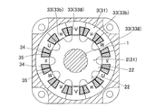
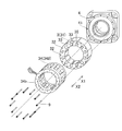
- FIG. 1st Embodiment It is sectional drawing of the switched reluctance motor by 1st Embodiment. It is a front view of the stator and rotor of a switched reluctance motor according to the first embodiment. It is a disassembled perspective view of the stator of the switched reluctance motor by a 1st embodiment. It is a circuit diagram of the drive circuit of the switched reluctance motor by 1st Embodiment. It is a figure for demonstrating operation
- the motor system 110 includes a switched reluctance motor 100 (see FIGS. 1 to 3) and a drive circuit 10 (see FIG. 4).
- the switched reluctance motor 100 is an example of a “motor”.
- the switched reluctance motor 100 includes a shaft 1, a rotor 2, a stator 3, a load side bracket 4, an antiload side bracket 5, a frame 6, and an encoder 7.
- the stator 3 is attached to the frame 6. Further, the rotor 2 and the stator 3 are disposed so as to face each other and are covered with the load side bracket 4 and the anti-load side bracket 5.
- the encoder 7 is arranged on the shaft 1 on the arrow X2 direction side.
- the rotor 2 is an example of a “moving element”.
- the stator 3 is an example of a “stator”.
- the rotor 2 is made of laminated steel plates and includes a substantially cylindrical rotor core 21.
- the rotor 2 (rotor core 21) is attached to the shaft 1. Further, the arrow X1 direction side and the arrow X2 direction side of the shaft 1 are rotatably supported by the load side bearing 8a and the anti-load side bearing 8b, respectively. Thereby, the rotor 2 is comprised rotatably.
- the rotor 2 (rotor core 21) includes a plurality (ten in the first embodiment) of protrusions 22. That is, the number of poles which is the number of the protrusions 22 of the rotor 2 is ten.
- the protrusion 22 is an example of a “mover side protrusion”.
- the stator 3 includes a stator core 31 made of laminated steel plates. Further, as shown in FIG. 3, the stator core 31 is divided into a plurality (in the first embodiment, 12), and each of the divided stator cores 31 is provided with a bolt fastening hole 32. Further, the load side bracket 4 is provided with a plurality of (12 in the first embodiment) tap holes 41 so as to correspond to the bolt fastening holes 32 of the stator core 31. The bolts 9 are fastened to the tap holes 41 via the bolt fastening holes 32 of the stator core 31 so that the divided individual stator cores 31 are fixed to the load side bracket 4.
- the stator 3 (stator core 31) includes a plurality (12 in the first embodiment) of protrusions 33, and the protrusions 33 have two sets of three phases.
- a coil 34 (a set of U phase, V phase and W phase, a set of u phase, v phase and w phase) is wound.
- the stator 3 includes a plurality of (twelve in the first embodiment) slots 35 that are arranged between the adjacent protrusions 33 and in which the coils 34 are arranged. That is, the number of slots of the stator 3 is 12.
- the protruding portion 33 is an example of a “stator side protruding portion”.
- one set of the two sets of three-phase coils 34 includes the U phase, the V phase, and the W phase, and the other set includes the U phase, the V phase, and the W phase. It includes u- phase, v- phase and w- phase in which the direction of current flow is opposite.
- the protrusion 33 includes a protrusion 33a around which one set of coils 34 (U phase, V phase, and W phase) of the two sets of three-phase coils 34 is wound, and the other set of coils 34. ( U phase, v phase, and w phase).
- the center in the circumferential direction of the projecting portion 33a coincides with the center in the circumferential direction of the projecting portion 22 of the rotor 2
- the center in the circumferential direction of the projecting portion 33b and the circumferential direction of the projecting portion 22 in the rotor 2 are the same. It is configured to deviate from the center.
- the center in the circumferential direction of the protruding portion 33a around which the V-phase coil 34 is wound and the center in the circumferential direction of the protruding portion 22 are coincident with each other, while the u- phase, v- phase, and w- phase coils.
- the center in the circumferential direction of the protrusion 33 b around which the winding 34 is wound is shifted from the center in the circumferential direction of the protrusion 22.
- the protrusion 33a is an example of a “stator-side protrusion” and a “first stator-side protrusion”.
- the protruding portion 33b is an example of a “stator side protruding portion” and a “second stator side protruding portion”.
- the stator 3 is wound with a projecting portion 33a around which the U-phase, V-phase, and W-phase are wound, and a u- phase, v- phase, and w- phase coil 34 in the circumferential direction.
- the protruding portions 33b are alternately arranged.
- the protrusion 33 of the stator 3 (stator core 31) has a w phase, a V phase, a u phase, a W phase, a v phase, a U phase, a w phase, a V phase, a u phase, a W phase, and a v phase.
- the U phase are arranged in this order in the circumferential direction (clockwise).
- the coil 34 is wound around one of the coils 34 wound around the circumferentially adjacent protruding portion 33a and the protruding portion 33b.
- the rotor 2 is driven by passing a current through one of the coils 34 to be driven.
- the drive circuit 10 (two sets of three-phase drive circuits 10a and 10b) is configured such that the U-phase to the W-phase, the v- phase to the u- phase, the W-phase to the V-phase, the u- phase to the w- phase, and the V-phase to U
- the current flowing through the coil 34 is switched in the order of phase, w- phase to v- phase (see FIG. 5).
- the coil 34 is formed of an air-core coil 34a wound by twelve concentrated windings.
- the air-core coil 34a is pressed by a mold and formed into a rectangular ring shape.
- a wiring board 34b is provided on the end side in the axial direction of the 12 air-core coils 34a, and the 12 air-core coils 34a and the wiring board 34b are covered with a mold resin.
- the drive circuit 10 is configured to include two sets of three-phase drive circuits 10 a and 10 b for allowing current to flow through two sets of three-phase coils 34.
- a power source 200 is connected to the drive circuit 10.
- Three-phase drive circuit 10a includes switching elements 11a, 11b and 11c, and diodes 12a, 12b and 12c.
- the three-phase drive circuit 10b includes switching elements 11d, 11e, and 11f and diodes 12d, 12e, and 12f.
- the two sets of three-phase coils 34 are connected in series with switching elements 11a, 11b and 11c of the three-phase drive circuit 10a and switching elements 11d, 11e and 11f of the three-phase drive circuit 10b, respectively. Yes.
- switching elements 11a, 11b, and 11c are connected to the U-phase, V-phase, and W-phase coils 34, respectively.
- switching elements 11d, 11e, and 11f are connected to the u- phase, v- phase, and w- phase coils 34, respectively.
- the rotor 2 is driven by turning on and off the switching elements 11a to 11f.
- the output side of one set of the two sets of three-phase drive circuits 10a and 10b and the input side of the other set are connected.
- the output side of the three-phase drive circuit 10a that supplies current to the U-phase, V-phase, and W-phase coils 34, and the three-phase drive circuit 10b that supplies current to the u- phase, v- phase, and w- phase coils 34. are connected at the neutral point N.
- the two sets of three-phase drive circuits 10a and 10b are configured such that current flows from the three-phase drive circuit 10a to the other set of three-phase drive circuits 10b.
- the rotor 2 switched reluctance motor 100
- the operation of the switched reluctance motor 100 according to the first embodiment will be described with reference to FIG.
- the numbers (0 to 9) of the protrusions 22 of the 10-pole rotor 2 are marked in the horizontal direction.
- periods t1 to t6 are written in the vertical direction.
- the right column of FIG. 5 shows phases in which current flows in each of the periods t1 to t6.
- fine hatching is added to the phase in which the current is flowing.
- rough hatching is attached
- the three-phase drive circuit 10a (see FIG. 3) is driven, so that a current flows through the U-phase coil. Thereafter, when the three-phase drive circuit 10b is driven, a current flows through the v- phase coil 34. That is, in the first embodiment, the two sets of the three-phase drive circuits 10a and 10b are alternately switched to be wound around one of the coils 34 wound around the circumferentially adjacent protruding portion 33a and the protruding portion 33b. A current is passed through one of the coils 34.
- the fifth and zeroth protrusions 22 are magnetized to the N pole.
- the first, fourth, sixth and ninth projections 22 are magnetized to the south pole.
- the third, fifth, eighth, and zeroth protrusions 22 are magnetized to the N pole.
- the fourth and ninth protrusions 22 are magnetized to the south pole.
- a current flows through the W-phase coil 34, and then a current flows through the u- phase coil 34.
- the third and eighth protrusions 22 are magnetized to the north pole.
- the second, fourth, seventh and ninth projections 22 are magnetized to the south pole.
- a current flows through the V-phase coil 34, and then a current flows through the u- phase coil 34.
- the first, third, sixth and eighth protrusions 22 are magnetized to the N pole.
- the second and seventh protrusions 22 are magnetized to the south pole.
- a current flows through the V-phase coil 34, and then a current flows through the w- phase coil 34.
- the first and sixth protrusions 22 are magnetized to the N pole.
- the 0, 2, 5 and 7th protrusions 22 are magnetized to the south pole.
- a current flows through the U-phase coil 34, and then a current flows through the w- phase coil 34.
- the first, fourth, sixth and ninth protrusions 22 are magnetized to the north pole.
- the 0th and 5th protrusions 22 are magnetized to the south pole.
- the stator 3 in which two sets of three-phase coils 34 are wound around the projecting portion 33, and two sets of currents to flow through the two sets of three-phase coils 34, respectively.
- Three-phase drive circuits 10a and 10b are provided.
- a common three-phase drive circuit 10a and The switched reluctance motor 100 can be driven by 10b. As a result, torque ripple can be reduced without separately forming a five-phase drive circuit.
- the three-phase drive circuits 10a and 10b are configured to include the switching elements 11a to 11f, and the two sets of three-phase coils 34 are respectively provided with the three-phase drive.
- the switching elements 11a to 11f of the circuits 10a and 10b are connected in series, and the switching elements 11a to 11f are turned on and off to drive the rotor 2.
- current can easily flow through the two sets of three-phase coils 34 by the three-phase drive circuits 10a and 10b.
- the output side of one set of the two sets of three-phase drive circuits 10a and 10b is connected to the input side of the other set.
- a bridge circuit can be constituted by two sets of three-phase drive circuits 10a and 10b.
- the two sets of three-phase drive circuits 10a and 10b are configured such that current flows from the three-phase drive circuit 10a to the three-phase drive circuit 10b.
- the current that has flowed through the U phase, the V phase, and the W phase can be easily passed through the u phase, the v phase, and the w phase.
- the rotor 2 is driven by alternately switching the two sets of the three-phase drive circuits 10a and 10b.
- the two sets of the three-phase drive circuits 10a and 10b can be easily controlled.
- the protrusions 33 a and the protrusions 33 b are alternately arranged in the circumferential direction on the stator 3.
- the two sets of the three-phase drive circuits 10a and 10b are alternately switched, and a current is passed through one of the coils 34 wound around the protrusion 33a and one of the coils 34 wound around the protrusion 33b.
- the rotor 2 can be rotated.
- any one of the coils 34 wound around the protrusion 33a adjacent in the circumferential direction and the protrusion The rotor 2 is configured to be driven by passing a current through one of the coils 34 wound around the 33b. Thereby, since the coil 34 through which the current flows is sequentially switched in the circumferential direction, the rotor 2 can be smoothly rotated.
- the number of poles which is the number of protrusions 22 of the rotor 2
- the number of slots of the stator 3 is set to 12.
- the stator 3 includes the w- phase, V-phase, u- phase, W-phase, v- phase, U-phase, w- phase, V-phase, u- phase, W-phase, v- phase, and U-phase coils 34.
- the stator 2 is arranged on the stator 3 so that the in-phase coils 34 face each other (at intervals of 180 degrees) (for example, the V-phase coil 34 and the V-phase coil 34 face each other). Can be rotated.
- the two sets of the three-phase drive circuits 10a and 10b are configured such that the U-phase to the W-phase, the v- phase to the u- phase, the W-phase to the V-phase, the u- phase to the w- phase, V
- the current flowing through the coil 34 is switched in the order from the phase to the U phase and from the w phase to the v phase.
- the w- phase, V-phase, u- phase, W-phase, v- phase, U-phase, w- phase, V-phase, u- phase, W-phase, v- phase and U-phase coils 34 are wound around the stator 3 in this order.
- the rotor 2 can be smoothly rotated.
- torque ripple reduction is required, such as for servo motor applications, the effect of torque ripple reduction by current intensity control can be combined with this embodiment to achieve a great effect.
- U-phase, V-phase, and W-phase coils 34 and u- phase, v- phase, and w- phase coils 34 are alternately arranged in the circumferential direction of the stator 3. Unlike the above, the U-phase, V-phase and W-phase coils 34 and the u- phase, v- phase and w- phase coils 34 are arranged so as to be adjacent in the axial direction.
- the switched reluctance motor 101 is an example of a “motor”.
- the switched reluctance motor 101 includes a shaft 1, a rotor 120 (rotors 120a and 120b (see FIG. 9)), and a stator 130 (stators 130a and 130b). Is provided. 6 and 7, the load side bracket 4 (see FIG. 1), the anti-load side bracket 5, the frame 6, and the encoder 7 are omitted.
- the rotor 120a is an example of a “moving element” and a “first moving element”.
- the rotor 120b is an example of a “moving element” and a “second moving element”.
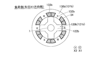
- the rotor 120a (rotor core 121a) includes a plurality (four in the second embodiment) of protrusions 122a. That is, the number of poles, which is the number of protrusions 122a of the rotor 120a, is four.
- the rotor 120b (rotor core 121b) includes a plurality (four in the second embodiment) of protrusions 122b. That is, the number of poles that is the number of the protrusions 122b of the rotor 120b is four.
- the rotor 120a and the rotor 120b are arranged adjacent to each other in the axial direction (direction in which the shaft 1 extends).
- the protrusions 122a and 122b are examples of the “mover-side protrusion”.
- the stator 130 includes a stator 130a (stator core 131a) having a protrusion 132a and a stator 130b (stator core 131b) having a protrusion 132b. It is configured. 6 and 7, the stator 130a (the U-phase, V-phase, and W-phase coils 34) and the stator 130b (the u- phase, v- phase, and w- phase coils 34) are arranged in the axial direction (shaft). 1 (the direction in which 1 extends). Note that the rotor 120a and the rotor 120b are disposed to face the stator 130a and the stator 130b, respectively. Further, as shown in FIGS.
- the stator 130a and the stator 130b are arranged such that the protrusions 132a of the stator 130a and the protrusions 132b of the stator 130b are alternately arranged when viewed from the axial direction. It is configured. Moreover, the protrusion part 122a of the rotor 120a and the protrusion part 122b of the rotor 120b are arrange
- the stator 130a is an example of a “stator” and a “first stator”.
- the stator 130b is an example of a “stator” and a “second stator”.
- the protrusion 132a is an example of a “stator-side protrusion” and a “first stator-side protrusion”.
- the protrusion 132b is an example of a “stator side protrusion” and a “second stator side protrusion”.
- three-phase drive circuits 10a and 10b are respectively provided for the coil 34 wound around the protrusion 132a and the coil 34 wound around the protrusion 132b, which are arranged so as to be adjacent to each other in the axial direction. Is connected). And it is comprised so that rotor 120a and 120b may be driven by switching two sets of three-phase drive circuits 10a and 10b alternately.
- the stator 130a (stator 130b) has a plurality of (six in the second embodiment) slots in which the coils 34 are arranged between the adjacent protrusions 132a (protrusions 132b).
- 133a (133b) is included. That is, the number of slots of the stator 130a and the stator 130b is 6, respectively.
- U-phase, W-phase, V-phase, U-phase, W-phase and V-phase coils 34 are arranged in this order in the circumferential direction (clockwise). . Further, as shown in FIG.
- the stator 130b has the u- phase, w- phase, v- phase, u- phase, w- phase and v- phase coils 34 arranged in this order in the circumferential direction (clockwise).
- the two sets of three-phase drive circuits 10a and 10b are composed of a V phase to a U phase, a w phase to a v phase, a U phase to a W phase, a v phase to a u phase, a W phase to a V phase, and a u phase to a w phase.
- the current flowing through the coil 34 is switched.
- FIG. 10 the numbers (1 to 8) of the protrusions 122a and 122b of the 8-pole (2 ⁇ 4 poles) rotor 120 are shown in the lateral direction. Has been. In addition, periods t1 to t6 are written in the vertical direction.
- the three-phase drive circuit 10a (see FIG. 3) is driven, so that a current flows through the V-phase coil. Thereafter, the three-phase drive circuit 10b is driven, whereby a current flows through the w- phase coil 34.
- the third, fourth, seventh, and eighth protrusions 122a (protrusion 122b) are magnetized to the N pole.
- the first, second, fifth and sixth protrusions 122a (protrusion 122b) are magnetized to the south pole.
- the first, fourth, fifth, and eighth protrusions 122a are magnetized to the N pole.
- the second, third, sixth and seventh protrusions 122a are magnetized to the south pole.
- a current flows through the U-phase coil 34, and then a current flows through the v- phase coil 34.
- the first, fourth, fifth and eighth protrusions 122a are magnetized to the N pole.
- the second, third, sixth and seventh protrusions 122a are magnetized to the south pole.
- the first, second, fifth and sixth protrusions 122a are magnetized to the N pole.
- the third, fourth, seventh and eighth projections 122a are magnetized to the south pole.
- a current flows through the W-phase coil 34, and then a current flows through the u- phase coil 34.
- the first, second, fifth and sixth protrusions 122a are magnetized to the N pole.
- the third, fourth, seventh and eighth projections 122a are magnetized to the south pole.
- a current flows through the W-phase coil 34, and then a current flows through the u- phase coil 34.
- the second, third, sixth, and seventh projections 122a are magnetized to the N pole.
- the first, fourth, fifth and eighth protrusions 122a are magnetized to the south pole.
- the stator 130 is configured to include the stator 130a having the protruding portion 132a and the stator 130b having the protruding portion 132b, and the stator 130a and the stator 130b are axially arranged.
- the stator 130a and the stator 130b are alternately arranged with the protrusions 132a of the stator 130a and the protrusions 132b of the stator 130b when viewed from the axial direction.
- the rotor 120 can be rotated by alternately switching between the two sets of the three-phase drive circuits 10a and 10b and causing a current to flow alternately between the protrusions 132a and 132b.
- the coil 34 wound around the protruding portion 132a and the coil 34 wound around the protruding portion 132b, which are arranged so as to be adjacent to each other in the axial direction The three-phase drive circuits 10a and 10b are connected and the two sets of three-phase drive circuits 10a and 10b are alternately switched to drive the rotor 120.
- torque ripple can be easily reduced using a general switched reluctance motor in which torque ripple is relatively large and general three-phase drive circuits 10a and 10b.
- the number of poles which is the number of protrusions 122a (projections 122b) of the rotor 120
- the number of slots of the stator 130a and the stator 130b is set to 6.
- the stator 130a includes the U-phase, W-phase, V-phase, U-phase, W-phase, and V-phase coils 34 arranged in this order in the circumferential direction, and the stator 130a.
- coils 34 of u phase, w phase, v phase, u phase, w phase and v phase are arranged in this order in the circumferential direction.
- the rotors 120 are arranged on the stator 130a and the stator 130b so that the in-phase coils 34 face each other (at intervals of 180 degrees) (for example, the V-phase coil 34 and the V-phase coil 34 face each other). Can be rotated in a balanced manner.
- the two sets of the three-phase drive circuits 10a and 10b are configured such that the V-phase to the U-phase, the w- phase to the v- phase, the U-phase to the W-phase, the v- phase to the u- phase, W
- the current flowing through the coil 34 is switched in the order from the phase to the V phase and from the u phase to the w phase.
- the U-phase, W-phase, V-phase, U-phase, W-phase, and V-phase coils 34 are arranged in this order in the circumferential direction in the stator 130a, and the u- phase, w- phase, v- phase are arranged in the stator 130b.
- the rotor 120 can be smoothly rotated.
- a magnet 141 is disposed between the rotor 120a and the rotor 120b of the switched reluctance motor 101 of the second embodiment.
- the switched reluctance motor 102 is an example of a “motor”.
- the switched reluctance motor 102 includes a shaft 1, a rotor 120 (rotors 120a and 120b), and a stator 130 (stators 130a and 130b).
- a connection board 142 for connecting the coil 34 wound around the stator 130a and the coil 34 wound around the stator 130b is provided between the stator 130a and the stator 130b.
- the dynamic brake (braking force which works by short-circuiting the coil 34) so that the shaft 1 may be surrounded.
- Magnet 141 is arranged. Further, the magnet 141 is formed in an annular shape as shown in FIG.
- the shaft 1 is made of a nonmagnetic member (for example, stainless steel, SUS316).
- Other configurations and operations of the third embodiment are the same as those of the second embodiment.
- the rotor 120a connected to the shaft 1 so as to face the stator 130a and the rotor 120b connected to the shaft 1 so as to face the stator 130b are provided.
- a magnet 141 for functioning the dynamic brake is disposed in a portion of the shaft 1 between the rotor 120b and the rotor 120b so as to surround the shaft 1.
- the annular magnet 141 is disposed so as to surround the shaft 1. Thereby, since the circumference
- the shaft 1 is made of stainless steel, which is a nonmagnetic member.
- a part of the magnetic flux of the magnet 141 is prevented from flowing into the shaft 1 side (the magnetic flux of the magnet 141 is weakened). It can suppress that a function (function as a brake) is reduced.
- the two sets of three-phase drive circuits include a u- phase, a v- phase, and a w- phase from a three-phase drive circuit that supplies current to the U-phase, V-phase, and W-phase coils.
- a current is passed through a three-phase drive circuit that passes current through the coil.
- You may comprise so that an electric current may be sent through the three-phase drive circuit which sends an electric current through the coil of V phase and W phase.
- the present invention may be applied to a motor other than the rotary type, such as a linear motor.
- the rotor has 10 poles and the stator has 12 slots.
- the rotor has 10 n poles (n is a natural number of 2 or more).
- the number of slots in the stator may be 12n (n is a natural number of 2 or more).
- the example in which the U-phase, V-phase, and W-phase coils and the u- phase, v- phase, and w- phase coils are alternately arranged in the circumferential direction on the stator is shown.
- the U-phase, V-phase, and W-phase coils and the u- phase, v- phase, and w- phase coils may not be alternately arranged in the circumferential direction.
- the example in which the protrusions 132a of the stator 130a and the protrusions 132b of the stator 130b are alternately arranged when viewed from the axial direction has been shown.
- the protrusions 132a of 130a and the protrusions 132b of the stator 130b may be overlapped, and the protrusions 122a of the rotor 120a and the protrusions 122b of the rotor 120b may be alternately arranged when viewed from the axial direction. .
- the rotor 120 has 4 poles and the stator 130a and the stator 130b have 6 slots.
- the rotor 120 has 2n (n May be 1 or a natural number of 3 or more), and the number of slots of the stator 130a and the stator 130b may be 3n (n is a natural number of 1 or 3).
- the shaft is made of stainless steel, which is a nonmagnetic member.
- the shaft may be made of a nonmagnetic member other than stainless steel.
Landscapes
- Engineering & Computer Science (AREA)
- Power Engineering (AREA)
- Synchronous Machinery (AREA)
- Control Of Electric Motors In General (AREA)
- Windings For Motors And Generators (AREA)
Abstract
Description
まず、図1~図4を参照して、第1実施形態によるモータシステム110の構成について説明する。モータシステム110は、スイッチトリラクタンスモータ100(図1~図3参照)と、駆動回路10(図4参照)とを含む。なお、スイッチトリラクタンスモータ100は、「モータ」の一例である。
次に、図6~図9を参照して、第2実施形態によるモータシステム111(スイッチトリラクタンスモータ101)の構成について説明する。この第2実施形態では、U相、V相およびW相のコイル34と、u相、v相およびw相のコイル34とがステータ3の周方向に交互に配置されていた上記第1実施形態と異なり、U相、V相およびW相のコイル34と、u相、v相およびw相のコイル34とが軸方向に隣接するように配置されている。なお、スイッチトリラクタンスモータ101は、「モータ」の一例である。
次に、図11を参照して、第3実施形態によるモータシステム112(スイッチトリラクタンスモータ102)の構成について説明する。この第3実施形態では、第2実施形態のスイッチトリラクタンスモータ101のロータ120aとロータ120bとの間に磁石141が配置されている。なお、スイッチトリラクタンスモータ102は、「モータ」の一例である。
2 ロータ(移動子)
3 ステータ(固定子)
10 駆動回路
10a、10b 3相駆動回路
11a、11b、11c、11d、11e、11f スイッチング素子
22 突出部(移動子側突出部)
33 突出部(固定子側突出部)
33a 突出部(固定子側突出部、第1固定子側突出部)
33b 突出部(固定子側突出部、第2固定子側突出部)
34 コイル
35、133a、133b スロット
100、101、102 スイッチトリラクタンスモータ(モータ)
110、111、112 モータシステム
120a ロータ(移動子、第1移動子)
120b ロータ(移動子、第2移動子)
122a、122b 突出部(移動子側突出部)
130a ステータ(固定子、第1固定子)
130b ステータ(固定子、第2固定子)
132a (固定子側突出部、第1固定子側突出部)
132b (固定子側突出部、第2固定子側突出部)
133a、133b スロット
141 磁石
Claims (20)
- モータ(100、101、102)と、
前記モータを駆動する駆動回路(10)とを備え、
前記モータは、
複数の移動子側突出部(22、122a、122b)を有する移動子(2、120a、120b)と、
複数の固定子側突出部(33、132a、132b)を有し、2組の3相のコイル(34)が前記固定子側突出部に巻回される固定子(3、130a、130b)とを含み、
前記固定子側突出部は、前記2組の3相のコイルのうちの一方の組のコイルが巻回される第1固定子側突出部(33a、132a)と、他方の組のコイルが巻回される第2固定子側突出部(33b、132b)とを有し、
前記第1固定子側突出部の周方向の中心と、前記移動子側突出部の周方向の中心とが一致する際に、前記第2固定子側突出部の周方向の中心と、前記移動子側突出部の周方向の中心とがずれるように構成されており、
前記駆動回路は、前記2組の3相のコイルにそれぞれ電流を流すための2組の3相駆動回路(10a、10b)を含む、モータシステム(110、111、112)。 - 前記3相駆動回路は、スイッチング素子(11a、11b、11c、11d、11e、11f)を含み、
前記2組の3相のコイルには、それぞれ、前記3相駆動回路のスイッチング素子が直列に接続されており、
前記スイッチング素子をオンオフすることにより、前記移動子を駆動するように構成されている、請求項1に記載のモータシステム。 - 前記2組の3相駆動回路のうちの一方の組の出力側と、他方の組の入力側とが接続されている、請求項1に記載のモータシステム。
- 前記2組の3相駆動回路は、前記2組の3相駆動回路のうちの一方の組の3相駆動回路から、他方の組の3相駆動回路に電流が流れるように構成されている、請求項3に記載のモータシステム。
- 前記2組の3相駆動回路を交互に切り替えることにより、前記移動子を駆動するように構成されている、請求項1に記載のモータシステム。
- 前記固定子には、周方向に、前記第1固定子側突出部と、前記第2固定子側突出部とが交互に配置されるように構成されている、請求項1に記載のモータシステム。
- 前記2組の3相駆動回路を交互に切り替えることにより、前記周方向に隣接する前記第1固定子側突出部に巻回されるコイルのいずれかと前記第2固定子側突出部に巻回されるコイルのいずれかとに電流を流すことにより、前記移動子を駆動するように構成されている、請求項6に記載のモータシステム。
- 前記固定子は、隣接する前記固定子側突出部の間に配置され、前記コイルが配置される複数のスロット(35)を含み、
前記移動子の移動子側突出部の数である極数は、10n(nは、1以上の自然数)であり、前記固定子のスロット数は、12n(nは、1以上の自然数)である、請求項1に記載のモータシステム。 - 前記移動子の極数は、10であり、前記固定子のスロット数は、12であり、
前記2組の3相のコイルのうちの一方の組は、U相、V相およびW相を含み、他方の組は、U相、V相およびW相とは電流の流れる方向が反対であるu相、v相およびw相を含み、
前記固定子には、w相、V相、u相、W相、v相、U相、w相、V相、u相、W相、v相およびU相のコイルがこの順で周方向に配置されるように構成されている、請求項8に記載のモータシステム。 - 前記2組の3相駆動回路は、U相からW相、v相からu相、W相からV相、u相からw相、V相からU相、w相からv相の順で、前記コイルに流す電流を切り替えるように構成されている、請求項9に記載のモータシステム。
- 前記固定子は、前記第1固定子側突出部を有する第1固定子(130a)と、前記第2固定子側突出部を有する第2固定子(130b)とを含み、
前記第1固定子と、前記第2固定子とが軸方向に隣接するように配置されている、請求項1に記載のモータシステム。 - 前記第1固定子と、前記第2固定子とは、軸方向から見て、前記第1固定子の第1固定子側突出部と、前記第2固定子の第2固定子側突出部とが交互に配置されるように構成されている、請求項11に記載のモータシステム。
- 軸方向に隣接するように配置されている前記第1固定子側突出部に巻回される前記コイルと前記第2固定子側突出部に巻回される前記コイルとには、それぞれ、前記3相駆動回路が接続され、
前記2組の3相駆動回路を交互に切り替えることにより、前記移動子を駆動するように構成されている、請求項11に記載のモータシステム。 - 前記固定子は、隣接する前記固定子側突出部の間に配置され、前記コイルが配置される複数のスロット(133a、133b)を含み、
前記移動子の移動子側突出部の数である極数は、2n(nは、1以上の自然数)であり、前記第1固定子および前記第2固定子のスロット数は、3n(nは、1以上の自然数)である、請求項11に記載のモータシステム。 - 前記移動子の極数は、4であり、前記第1固定子および前記第2固定子のスロット数は、それぞれ、6であり、
前記2組の3相のコイルのうちの一方の組は、U相、V相およびW相を含み、他方の組は、U相、V相およびW相とは電流の流れる方向が反対であるu相、v相およびw相を含み、
前記第1固定子には、U相、W相、V相、U相、W相およびV相のコイルがこの順で周方向に配置されるとともに、前記第2固定子には、u相、w相、v相、u相、w相およびv相のコイルがこの順で周方向に配置されるように構成されている、請求項14に記載のモータシステム。 - 前記2組の3相駆動回路は、V相からU相、w相からv相、U相からW相、v相からu相、W相からV相、u相からw相の順で、前記コイルに流す電流を切り替えるように構成されている、請求項15に記載のモータシステム。
- 前記移動子は、前記第1固定子に対向するようにシャフト(1)に接続される第1移動子(120a)と、前記第2固定子に対向するように前記シャフトに接続される第2移動子(120b)とを含み、
前記第1移動子と前記第2移動子との間の前記シャフトの部分には、前記シャフトを取り囲むように磁石(141)が配置されている、請求項11に記載のモータシステム。 - 前記シャフトは、非磁性の部材からなる、請求項17に記載のモータシステム。
- 複数の移動子側突出部(22、122a、122b)を含む移動子(2、120a、120b)と、
複数の固定子側突出部(33、132a、132b)を含み、2組の3相駆動回路(10a、10b)からそれぞれ電流が流される2組の3相のコイル(34)が前記固定子側突出部に巻回される固定子(3、130a、130b)とを備え、
前記固定子側突出部は、前記2組の3相のコイルのうちの一方の組のコイルが巻回される第1固定子側突出部(33a、132a)と、他方の組のコイルが巻回される第2固定子側突出部(33b、132b)とを含み、
前記第1固定子側突出部の周方向の中心と、前記移動子側突出部の周方向の中心とが一致する際に、前記第2固定子側突出部の周方向の中心と、前記移動子側突出部の周方向の中心とがずれるように構成されている、モータ(100、101、102)。 - 複数の移動子側突出部(22、122a、122b)を含む移動子(2、120a、120b)と、複数の固定子側突出部を含み、2組の3相駆動回路(10a、10b)からそれぞれ電流が流される2組の3相のコイルが前記固定子側突出部に巻回される固定子(3、130a、130b)とを備え、前記固定子側突出部は、前記2組の3相のコイルのうちの一方の組のコイルが巻回される第1固定子側突出部(33a、132a)と、他方の組のコイルが巻回される第2固定子側突出部(33b、132b)とを含み、前記第1固定子側突出部の周方向の中心と、前記移動子側突出部の周方向の中心とが一致する際に、前記第2固定子側突出部の周方向の中心と、前記移動子側突出部の周方向の中心とがずれるように構成されている、モータに用いられる、駆動回路(10)。
Priority Applications (4)
| Application Number | Priority Date | Filing Date | Title |
|---|---|---|---|
| PCT/JP2012/082971 WO2014097432A1 (ja) | 2012-12-19 | 2012-12-19 | モータシステム、モータおよび駆動回路 |
| CN201290001381.XU CN204810091U (zh) | 2012-12-19 | 2012-12-19 | 电机系统、电机和驱动电路 |
| JP2014552822A JPWO2014097432A1 (ja) | 2012-12-19 | 2012-12-19 | モータシステム、モータおよび駆動回路 |
| US14/742,708 US20150288314A1 (en) | 2012-12-19 | 2015-06-18 | Motor system, motor, and drive circuit |
Applications Claiming Priority (1)
| Application Number | Priority Date | Filing Date | Title |
|---|---|---|---|
| PCT/JP2012/082971 WO2014097432A1 (ja) | 2012-12-19 | 2012-12-19 | モータシステム、モータおよび駆動回路 |
Related Child Applications (1)
| Application Number | Title | Priority Date | Filing Date |
|---|---|---|---|
| US14/742,708 Continuation US20150288314A1 (en) | 2012-12-19 | 2015-06-18 | Motor system, motor, and drive circuit |
Publications (1)
| Publication Number | Publication Date |
|---|---|
| WO2014097432A1 true WO2014097432A1 (ja) | 2014-06-26 |
Family
ID=50977814
Family Applications (1)
| Application Number | Title | Priority Date | Filing Date |
|---|---|---|---|
| PCT/JP2012/082971 Ceased WO2014097432A1 (ja) | 2012-12-19 | 2012-12-19 | モータシステム、モータおよび駆動回路 |
Country Status (4)
| Country | Link |
|---|---|
| US (1) | US20150288314A1 (ja) |
| JP (1) | JPWO2014097432A1 (ja) |
| CN (1) | CN204810091U (ja) |
| WO (1) | WO2014097432A1 (ja) |
Cited By (1)
| Publication number | Priority date | Publication date | Assignee | Title |
|---|---|---|---|---|
| JP7076688B1 (ja) | 2021-09-02 | 2022-05-30 | 国立大学法人大阪大学 | モータ装置 |
Families Citing this family (4)
| Publication number | Priority date | Publication date | Assignee | Title |
|---|---|---|---|---|
| RU2546406C1 (ru) * | 2013-11-29 | 2015-04-10 | Общество с ограниченной ответственностью "Эйдос-Медицина" | Привод для генерации обратной тактильной связи на инструмент по усилию |
| EP3451507A1 (de) * | 2017-08-31 | 2019-03-06 | Siemens Aktiengesellschaft | Elektrische rotierende maschine für einen gondelantrieb |
| JP6990210B2 (ja) * | 2019-05-09 | 2022-02-03 | 本田技研工業株式会社 | 回転電機駆動ユニット |
| GB2626771B (en) * | 2023-02-02 | 2025-08-27 | Rolls Royce Plc | Electric machine assembly |
Citations (1)
| Publication number | Priority date | Publication date | Assignee | Title |
|---|---|---|---|---|
| JPH04281390A (ja) * | 1991-03-07 | 1992-10-06 | Secoh Giken Inc | 高速電動機 |
Family Cites Families (1)
| Publication number | Priority date | Publication date | Assignee | Title |
|---|---|---|---|---|
| US5274287A (en) * | 1991-03-07 | 1993-12-28 | Kabushikigaisha Sekogiken | High-speed motor |
-
2012
- 2012-12-19 JP JP2014552822A patent/JPWO2014097432A1/ja active Pending
- 2012-12-19 CN CN201290001381.XU patent/CN204810091U/zh not_active Expired - Fee Related
- 2012-12-19 WO PCT/JP2012/082971 patent/WO2014097432A1/ja not_active Ceased
-
2015
- 2015-06-18 US US14/742,708 patent/US20150288314A1/en not_active Abandoned
Patent Citations (1)
| Publication number | Priority date | Publication date | Assignee | Title |
|---|---|---|---|---|
| JPH04281390A (ja) * | 1991-03-07 | 1992-10-06 | Secoh Giken Inc | 高速電動機 |
Cited By (3)
| Publication number | Priority date | Publication date | Assignee | Title |
|---|---|---|---|---|
| JP7076688B1 (ja) | 2021-09-02 | 2022-05-30 | 国立大学法人大阪大学 | モータ装置 |
| WO2023032332A1 (ja) * | 2021-09-02 | 2023-03-09 | 国立大学法人大阪大学 | モータ装置 |
| JP2023036393A (ja) * | 2021-09-02 | 2023-03-14 | 国立大学法人大阪大学 | モータ装置 |
Also Published As
| Publication number | Publication date |
|---|---|
| CN204810091U (zh) | 2015-11-25 |
| US20150288314A1 (en) | 2015-10-08 |
| JPWO2014097432A1 (ja) | 2017-01-12 |
Similar Documents
| Publication | Publication Date | Title |
|---|---|---|
| US9712028B2 (en) | Stator having three-line connection structure, BLDC motor using same, and driving method therefor | |
| US7408281B2 (en) | Stator and brushless motor | |
| JP5304427B2 (ja) | 回転電機の駆動システム | |
| US5834865A (en) | Hybrid stepping motor | |
| JP6010416B2 (ja) | 3相永久磁石モータ | |
| US20130015742A1 (en) | Synchronous motor | |
| EP1505714B1 (en) | Dynamo electric machine | |
| KR20180062939A (ko) | 회전 전기 기기 | |
| WO2014097432A1 (ja) | モータシステム、モータおよび駆動回路 | |
| JP2007259541A (ja) | 永久磁石式電動機 | |
| US20080290754A1 (en) | AC Motor | |
| JP5907813B2 (ja) | ブラシレスモータ | |
| JP2008141803A (ja) | ブラシレスモータ | |
| JP5334167B2 (ja) | 磁石式発電機 | |
| JP2017028972A (ja) | 交流励磁同期回転電機 | |
| JP6190694B2 (ja) | ロータ、ステータ、及び、モータ | |
| JP2012200127A (ja) | 電気機械およびその製造方法 | |
| JP2011239589A (ja) | 多相モータ | |
| JP5822947B2 (ja) | 回転電機 | |
| KR100932687B1 (ko) | 고 토크밀도 하이브리드 스테핑 모터 | |
| JP2007089260A (ja) | リニア同期モータ | |
| JP5309694B2 (ja) | 永久磁石式回転機の製造方法 | |
| JP5467840B2 (ja) | 永久磁石モータ | |
| JP5494843B2 (ja) | 永久磁石式回転機の製造方法 | |
| WO2017017769A1 (ja) | 回転電機 |
Legal Events
| Date | Code | Title | Description |
|---|---|---|---|
| WWE | Wipo information: entry into national phase |
Ref document number: 201290001381.X Country of ref document: CN |
|
| 121 | Ep: the epo has been informed by wipo that ep was designated in this application |
Ref document number: 12890453 Country of ref document: EP Kind code of ref document: A1 |
|
| ENP | Entry into the national phase |
Ref document number: 2014552822 Country of ref document: JP Kind code of ref document: A |
|
| NENP | Non-entry into the national phase |
Ref country code: DE |
|
| 122 | Ep: pct application non-entry in european phase |
Ref document number: 12890453 Country of ref document: EP Kind code of ref document: A1 |