WO2014097413A1 - 作業支援端末および作業支援システム - Google Patents
作業支援端末および作業支援システム Download PDFInfo
- Publication number
- WO2014097413A1 WO2014097413A1 PCT/JP2012/082860 JP2012082860W WO2014097413A1 WO 2014097413 A1 WO2014097413 A1 WO 2014097413A1 JP 2012082860 W JP2012082860 W JP 2012082860W WO 2014097413 A1 WO2014097413 A1 WO 2014097413A1
- Authority
- WO
- WIPO (PCT)
- Prior art keywords
- image
- work
- information
- terminal
- work support
- Prior art date
- Legal status (The legal status is an assumption and is not a legal conclusion. Google has not performed a legal analysis and makes no representation as to the accuracy of the status listed.)
- Ceased
Links
Images











Classifications
-
- G—PHYSICS
- G09—EDUCATION; CRYPTOGRAPHY; DISPLAY; ADVERTISING; SEALS
- G09G—ARRANGEMENTS OR CIRCUITS FOR CONTROL OF INDICATING DEVICES USING STATIC MEANS TO PRESENT VARIABLE INFORMATION
- G09G5/00—Control arrangements or circuits for visual indicators common to cathode-ray tube indicators and other visual indicators
- G09G5/14—Display of multiple viewports
-
- G—PHYSICS
- G09—EDUCATION; CRYPTOGRAPHY; DISPLAY; ADVERTISING; SEALS
- G09G—ARRANGEMENTS OR CIRCUITS FOR CONTROL OF INDICATING DEVICES USING STATIC MEANS TO PRESENT VARIABLE INFORMATION
- G09G2340/00—Aspects of display data processing
- G09G2340/04—Changes in size, position or resolution of an image
- G09G2340/0492—Change of orientation of the displayed image, e.g. upside-down, mirrored
-
- G—PHYSICS
- G09—EDUCATION; CRYPTOGRAPHY; DISPLAY; ADVERTISING; SEALS
- G09G—ARRANGEMENTS OR CIRCUITS FOR CONTROL OF INDICATING DEVICES USING STATIC MEANS TO PRESENT VARIABLE INFORMATION
- G09G2340/00—Aspects of display data processing
- G09G2340/12—Overlay of images, i.e. displayed pixel being the result of switching between the corresponding input pixels
Definitions
- the present invention relates to a work support terminal and a work support system using the work support terminal.
- Content necessary for augmented reality technology is composed of information necessary for superimposed display of character strings, CG images, and the like, and information indicating the correspondence between these and the real world. For this reason, a technique for easily associating information necessary for superimposed display of character strings, CG images, and the like with the real world is required.
- Patent Document 1 As a technology using augmented reality technology, for example, Patent Document 1 can be cited.
- an imaged observation target is specified by image recognition technology, and additional image data associated with the specified observation target in advance is processed according to the state of the observation target, and processed on the image of the observation target It is described that the added image is superimposed and displayed.
- augmented reality technology When augmented reality technology is used to support a worker, information by a character string or a CG image is superimposed and displayed on an image obtained by photographing the real world or at an appropriate position in the worker's field of view. It is conceivable to provide supplementary information. This requires a technique for identifying where an object to be worked exists on an image obtained by photographing the real world (hereinafter referred to as a visual field image) or in the field of view of the worker.
- a visual field image an image obtained by photographing the real world
- Patent Document 1 an object on an image obtained by photographing the real world is specified using a pattern matching technique which is one of well-known image recognition techniques. That is, an image of a characteristic part of an object is prepared as a template, and an object in an image taken of the real world is detected by detecting a part having a high similarity to the template from an image taken of the real world. It is a technology to identify. In this case, since it is assumed that the portion used as the template is contained in an image obtained by photographing the real world, a template smaller than the real world image is used. In order to specify a work target with high accuracy using such a template, it is necessary that the entire object is photographed on an image obtained by photographing the real world.
- Patent Document 1 the augmented reality technology using a three-dimensional image as disclosed in Patent Document 1 is applied to work support in which a lot of image processing is performed and a large number of different field-of-view images are taken for each work. That is practically difficult.
- An object of the present invention is to realize a technology that supports an operator who performs various operations such as construction and maintenance / inspection of facilities by using augmented reality technology, and is particularly necessary for augmented reality technology. It is to realize a work support technology that enables easy creation of content that can be specified with high accuracy even when only a part of the work target is shown on an image of the real world. .
- the present application includes a plurality of means for solving the above-described problems.
- a work support terminal which is a field camera for photographing a worker's field of view, and a first camera photographed by the field camera.
- a storage unit that stores an image and a second image in which a plurality of objects to be worked are reflected, and a correspondence relationship between the first image and the second image
- An image processing unit that identifies the object shown in the first image, and a display unit that displays information about the target shown in the first image, The second image is characterized in that the entire object is reflected in the second image.
- the work target can be specified with high accuracy, and the operator's work is easy. become.
- FIG. 10 is a diagram showing a flow of processing in Step 2103.
- FIG. 1 is a block diagram when the work support terminal according to the first embodiment of the present invention is realized on a computer.
- Reference numeral 101 in FIG. 1 denotes an information processing apparatus for executing various programs necessary for the work support terminal.
- the input device 102 includes a camera for inputting, to the work support terminal, an image obtained by photographing a place where the work is performed during work or an image in a visual line direction of the worker who is working, and a work support terminal. It is comprised from the input means to computers, such as a mouse
- the output device 103 is a means for displaying an image to be presented to an operator, and a monitor of a portable computer, a head mounted display (HMD) that is a head mounted display device, or the like can be used.
- the storage device 104 is a means for storing various programs necessary for the work support terminal, and the work information registration program 105 defines the position and area of the work object in the real world and stores information to be presented to the worker. It is a program for creating content necessary for augmented reality technology by setting registration and correspondence between them.
- the work support control program 106 obtains a correspondence relationship between the two images by matching the visual field image and a panoramic image to be described later, and superimposes and displays the information created by the work information registration program 105 on the visual field image. It is a program for performing processing that supports the workers inside.
- the image storage unit 107 stores a panoramic image that is an image obtained by photographing the panoramic view of the work area where the worker performs the work.
- a panoramic image is an image in which a plurality of objects are shown in one image in the work area, and each object is shown so as to be entirely contained. Such an image is referred to as a panoramic image in this specification and is used as a matching template.
- the indicating instrument of the apparatus is an object to be operated, if there are twelve indicating instruments in front of the apparatus, it indicates an image in which all twelve objects are shown on one sheet.
- This panoramic image is used for defining the position and area of the work object in the work information registration program 105, and for matching with the visual field image in the work support control program.
- the work information storage unit 108 stores information related to a work target defined on a panoramic image and information representing a work procedure, which are information necessary for support of the worker.
- FIG. 2 is a schematic diagram showing the appearance of the work support terminal according to the first embodiment and the situation in which work is performed using it.
- reference numeral 201 denotes equipment that serves as a work area.
- Reference numeral 202 denotes a camera for capturing a visual field image that is an image in the direction of the operator's line of sight
- 203 denotes an HMD for displaying an image obtained by superimposing the work information data stored in the work information storage unit 108 on the visual field image. It is.
- the HMD in addition to a type of HMD that displays an image obtained by superimposing work information data stored in the work information storage unit 108 on a visual field image captured by the camera 202, only work information data is displayed, and an actual work area is displayed.
- Reference numeral 204 denotes a portable computer that executes the work information registration program 105 and the work support control program 106 and has an image storage unit 107 and a work information storage unit 108.
- the display device 205 of the portable computer 204 is equipped with a touch panel as an input device 102 for an operator to perform input necessary for executing various processes.
- FIG. 3 shows a flow of processing for registering a panoramic image and work information in the work information registration program 105.
- a panoramic image representing the panoramic view of the work area is acquired by a camera which is one of the input devices 102, or is selected from panoramic images already stored in the image storage unit 107. In the configuration shown in FIG. 2, it can be acquired using the camera 202.
- the position and area of the work object on the panoramic image are defined.
- the work target refers to a target such as a meter or a switch included in the work area, which is visually confirmed by the worker during the work or some operation is performed.
- step 303 information relating to a work procedure indicating what kind of work is to be performed in what order with respect to the work target defined in step 302 is registered.
- the panoramic image for which registration of information has been completed is stored in the image storage unit 107.
- a panoramic image registration 301, a work target registration 302, and a work procedure registration 303 are executed in order. It is also possible to start the process from the registration 302 or to start the process from the registration 303 of the work procedure in a state where the registration of the work target is completed.
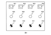
- Fig. 4 shows an example of a panoramic image. 4 is an image obtained by photographing the equipment 201 in FIG. 2 from the front.
- 801, 802, 803 and 804 are ammeters
- 805, 806, 807 and 808 are operation lamps indicating the state of the equipment
- 809, 810, 811 and 812 are operation buttons for operating / stopping the equipment. Suppose there is. These ammeters, operation lamps, and operation buttons will be described below as work targets.
- Fig. 5 shows the format for storing information about work objects.
- 1001 is the work area name
- 1002 is the file name of the panoramic image
- 1003 is the number of registered work objects.
- Reference numerals 1004 and 1007 are registered work object names
- 1005 and 1008 are explanatory texts indicating details about the registered work objects
- 1006 and 1009 are vertex coordinates of a rectangular area representing the work object area on the full view image.
- the details regarding the work target not only the explanatory text but also any information related to the work target, such as a specification of the work target and a CG image, can be registered.
- the vertex coordinates 1006 and 1009 are stored in a format including a set of four coordinate points serving as the vertices of the rectangular area, which is a set of X-axis coordinates and Y-axis coordinates representing a position on the whole view image.
- the work target area can be represented not only by a rectangle but also by a circle, an arbitrary polygon, or the like.
- 1006 and 1009 can be represented by the center coordinates and radius of the circle.
- 1006 and 1009 can be expressed in a format including a set of coordinates of the number of vertices.
- the rectangular area is set by moving the mouse pointer to the position of the upper left vertex of the rectangle that is the work target area and dragging the mouse. After setting the rectangular area, the details of the work target are input, and the registration of the work target is completed.
- the work target area is represented by a rectangular area.
- the rectangular area set in the same manner as described above represents the work target area.
- a circle that is a circumscribed rectangle of the circle to be represented may be obtained as a circle that represents the work area.
- the radius may be specified by dragging.
- the position of the vertex coordinates may be designated by clicking with the mouse in order.
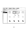
- FIG. 6 shows a state after two work targets are registered for the whole view image of FIG.
- the work target list 1301 indicates that two work targets “ammeter 1” and “ammeter 2” are registered. Further, the background color of “Ammeter 2” is black, which indicates that “Ammeter 2” is in a selected state. Selection of a work target in the work target list 1301 can change the name of the target work target by clicking with the mouse or tapping the touch panel. Further, in FIG. 6, a rectangular area 1302 on the whole view image of the selected “ammeter 2” is displayed, and details 1303 of the registered “ammeter 2” are displayed beside the rectangular area. ing. As information regarding the work target to be displayed on the panoramic image, only the rectangular area may be displayed, and details may be displayed when the rectangular area is clicked with the mouse or the touch panel is tapped.
- Fig. 7 shows the format for storing information related to work procedures.
- 1501 is a work name
- 1502 is the number of registered work items.
- 1503 and 1508 are work item names
- 1504 and 1509 are descriptive texts indicating the contents of the registered work items
- 1505 and 1510 are the numbers of work objects associated with each work item.
- As the contents related to the work item not only the explanatory text but also any information indicating the contents of the work item such as a separately created work procedure manual and CG image can be registered.
- reference numerals 1506, 1507, 1511 and 1512 denote work target names associated with the work items.
- the work item mentioned here is an item indicating the content of the work such as “confirming the value of the ammeter”, for example, and information on “ammeter 1” and “ammeter 2” used in the work item is set as a work target. Yes.
- the registered work target is selected in step 302, the work item name and work content are input, and the registration is completed.
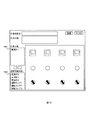
- An example of the screen displayed at the time of registration is shown in FIG.
- 1601 is a field for inputting a work item name
- 1602 is an area for inputting work contents
- 1603 is an area for displaying a list of work objects corresponding to the work items.
- 1604 a list of registered work targets is displayed.
- Correspondence with work items can be set or canceled by 1605 and 1606.
- Reference numeral 1607 denotes an area for displaying a panoramic image for confirming a work target associated with the work item.
- FIG. 11 shows a state after two work items are registered with respect to the whole view image of FIG.
- the names of registered work items, “Confirm Ammeter” and “Confirm Operation Lamp” are displayed.
- “Confirm Ammeter” in 1901 is selected by clicking with the mouse or tapping the touch panel, as shown in 1902 of FIG. 11, the display of the selected work item name changes to a state indicating that it has been selected.
- work target areas 1903, 1904, 1905, and 1906 corresponding to the work items are displayed on the full-view image.
- information indicating the order in which work objects are registered on the screen of FIG. 8 is displayed as indicated by the numerical values at the upper left of 1903, 1904, 1905 and 1906.
- each work object may be displayed. Or you may make it display the detail of a work object by clicking with a mouse
- the work information registration program 105 performs panoramic image registration, work target registration, and work procedure registration by the method described above.
- the work support control program 106 superimposes and displays information using the augmented reality technology based on information on the work procedure registered by the work information registration program, thereby supporting the work of the worker.
- FIG. 12 shows the flow of work using the work support terminal.
- the worker who performs the work takes a field-of-view image with the camera 202 (step 2001).
- the work support terminal performs matching between the visual field image obtained by capturing a range smaller than the full-view image and the full-view image (step 2002), and in step 2003, the correspondence relationship according to the position of the visual field image in the full-view image is specified.
- Information on the work item and work object corresponding to the position specified in step 2003 is displayed on the display unit of the work support terminal (step 2004), and the worker performs work based on the displayed information (step 2005). ).
- the flow of the work support control program from step 2002 to step 2004 in FIG. 20 will be described in detail with reference to FIGS.
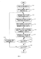
- FIG. 13 shows the flow of processing of the work support control program 106.
- the work performed by the worker is selected and read in step 2101.
- information related to the work 1501 selected by the worker may be read from the information related to the work procedure stored in the format shown in FIG.
- step 2102 information related to the first work item 1503 is selected from the read information related to the work 1501.
- step 2103 the visual field image acquired from the camera 202 is matched with the full view image to obtain the correspondence between the visual field image and the full view image.
- the format shown in FIG. 7 does not include the information of the panoramic image, but the related panoramic image can be specified by tracing the information regarding the work target from the work target name included therein.
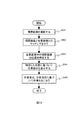
- FIG. 14 shows a detailed flow of the processing performed in step 2103.
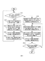
- rough matching is performed in steps 2201 to 2205
- detailed matching is performed in steps 2206 to 2210.
- step 2201 there are three types: a position where matching between the view image and the full view image, a rotation angle of the view image when matching with the full view image, and the size of the view image when matching with the full view image are performed.
- a combination that has not been processed in step 2202 and thereafter is searched, and if the corresponding combination remains, the process proceeds to step 2202.
- the process proceeds to step 2206.
- an upper limit value, a lower limit value, and a change amount of each parameter are obtained, and the parameter combination is obtained by changing each parameter within these ranges.
- step 2202 one parameter combination that has not been processed is selected. Further, in 2203, an image of an area determined by the selected combination of parameters is cut out from the full-view image and adjusted to the same size as the visual field image.
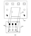
- FIG. 15 shows an image of matching between the field-of-view image and the full-view image when the change in parameters is fixed for each of the position, rotation angle, and size.
- reference numeral 2301 denotes a field-of-view image
- 2302, 2303, and 2304 denote panoramic images.
- each rectangular area indicated by 2305 is an area on the whole view image for matching with the visual field image when only the matching position is changed.
- each rectangular area indicated by 2306 is an area on the whole view image for matching with the visual field image when only the rotation angle is changed.
- each rectangular area indicated by 2307 becomes an area on the whole view image for matching with the visual field image when only the size is changed. If there are a plurality of objects having the same shape in the whole view image, marking 4501 is provided on a part of the actual apparatus and the whole view image is captured in a form including the marking 4501 as shown in FIG. Good. The positional relationship between the visual field image and the panoramic image is clarified by the marking position.
- a conversion matrix for converting the image on the full-view image to the same size as the field-of-view image is obtained based on the position, size, and rotation angle.
- the image of the region to be cut out is cut out, and the cut out image is adjusted to the same size as the view image.
- Such deformation can be easily realized by using a technique called affine transformation used for movement and deformation of figures.
- step 2204 the visual field image and the image cut out from the full view image are matched (compared) to obtain the similarity.
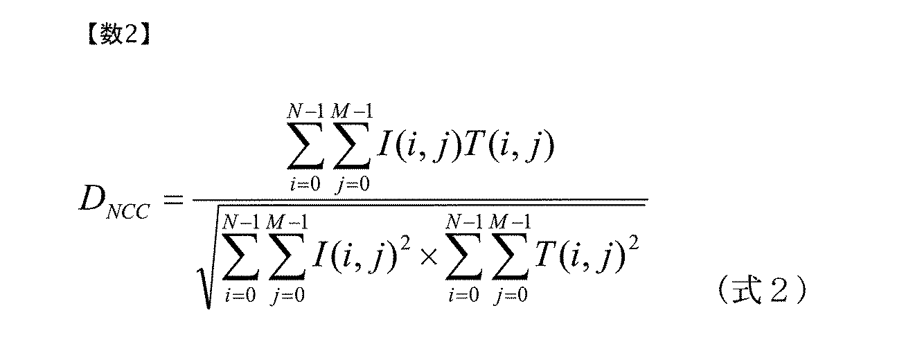
- any calculation formula can be used as long as it is various calculation formulas generally used in image recognition. For example, the following equation 1
- SSD Sum of Squared Differences
- Normalized cross-correlation defined in (1) can be used.
- step 2205 the obtained combination of similarity and parameter is stored, and the process returns to step 2201.
- step 2206 a combination of parameters having the highest similarity among the obtained similarities is selected, and an area on the whole view image determined by these parameters is determined as an area visible in the visual field image. It is set as the initial value for the processing to be performed thereafter. It should be noted that since Equation 1 takes a smaller value as the similarity is higher, and Equation 2 takes a larger value as the similarity is higher, the method for determining the degree of similarity needs to be changed in accordance with the calculation formula used.
- each vertex representing the area is changed based on the change in similarity when the vertex coordinates of the area on the set panoramic image are slightly moved. This is because, when the field of view image actually shot is not the one that was taken from the front, unlike the whole view image, the position of each vertex coordinate is adjusted for the purpose of tilting the whole view image according to the view image. It is a step. In this step, the degree of similarity between the images is calculated while changing each vertex of the rectangular area on the whole view image little by little in the X-axis and Y-axis directions, and the vertex is changed.
- step 2208 an area on the panoramic image represented by the newly determined vertex is cut out, and the size is adjusted so that it looks like the same inclination as the visual field image.
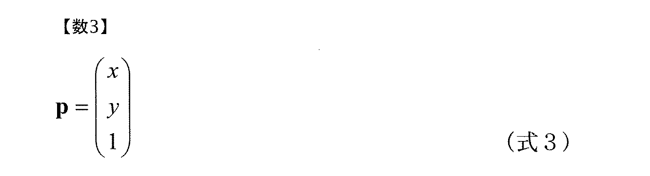
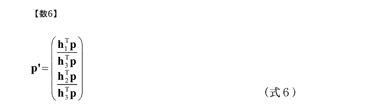
- This process can be easily realized by using a technique called projective transformation. For example, an arbitrary position on the panoramic image
- a transformation matrix H is obtained.
- s is a scalar quantity.
- the transformation matrix H in (Equation 5) is obtained from the correspondence between the vertex coordinates representing the region on the whole-view image and each vertex of the visual field image, and the whole-view image is transformed by using the obtained transformation matrix H. Then, the region on the whole view image is cut out and adjusted to the same size as the view image. Note that an arbitrary coordinate p on the panoramic image is associated with a coordinate p ′ on an image having the same size as the field-of-view image by the following expression.
- step 2209 the similarity between the image cut out from the whole view image and the visual field image is obtained as described above.
- the calculation formula for similarity may be the same as that used in step 2204, or a different calculation formula may be used.
- step 2210 the similarity between the region on the panoramic image and the visual field image before the change in step 2207 is compared with the similarity between the region on the panoramic image and the visual field image after the change in step 2207. Then, it is determined whether the difference is less than a predetermined threshold. If the difference in similarity is not less than the threshold, the process returns to step 2207.
- step 2206 a predetermined number of candidates are selected from those with the highest similarity, and the processing after step 2207 is performed on all the selected candidates. As a result, the one with the highest similarity is finally obtained. You may make it select as an appropriate matching result.
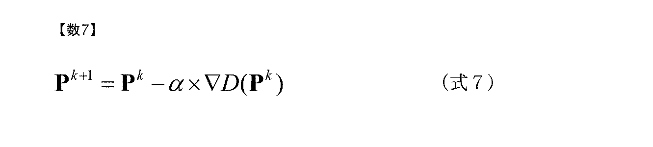
- step 2207 The processing from step 2207 to step 2210 is the same as the algorithm generally used for the optimization problem. For this reason, as a method for changing the vertex coordinates in Step 2207, various algorithms used in the optimization problem, for example, a method such as the steepest descent method and the Newton method can be used as they are. For example, when the steepest descent method is used, in step 2207, P k is an eight-dimensional vector composed of four vertex coordinates at a certain time point.
- ⁇ is a predetermined constant
- D (P k ) is the similarity between the area on the whole-view image indicated by P k and the visual field image
- ⁇ is an operator representing partial differentiation.
- step 2104 in FIG. 13 based on the correspondence relationship between the coordinates of the visual field image and the panoramic image determined in step 2103, a transformation matrix for associating the region on the panoramic image with the visual field image is obtained.
- This transformation matrix is the same as the projection transformation matrix obtained by (Equation 5) using step 2208.
- step 2105 an area on the panoramic image of the work target associated with the selected work item is acquired from the information related to the work target, and the acquired area is viewed using the transformation matrix obtained above. Convert to correspond to the area on the image.
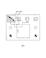
- FIG. 16 shows an example in which a work target area on the full-view image is converted into an area on the visual field image. In FIG. 16, areas 2701 and 2702 on the full-view image are converted into areas 2703 and 2704 on the view image.
- step 2106 the coordinates of the work target area converted as the area on the visual field image in step 2105 are compared with the coordinates of the work target in the full-view image registered as shown in FIG.
- the work target to be determined is determined.
- information related to the work target determined to exist on the visual field image is retrieved from the registration information in FIG. 7 and superimposed on the visual field image.
- information on the selected work item name and work content is also superimposed on the visual field image. In the case of a see-through display device, only information related to the work target, item names, and work content are displayed.
- the format shown in FIG. 5 is used.
- a work target in the field-of-view image can be specified.
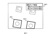
- FIG. 17 shows an example in which work target areas 2801 and 2802 and work item names and work contents 2803 are superimposed on the field-of-view image.
- FIG. 17 only the rectangle indicating the work target area is superimposed and displayed as the information related to the work target. However, details regarding each work target may be superimposed and displayed. In addition, any method can be used for the information regarding the work target as long as the method can be easily identified on the visual field image.
- the work item name and work content 2803 are displayed at the upper right of the screen, the display position may be changed based on the position of the work target.
- step 2108 in FIG. 13 it is determined whether or not the selected work item is completed. If it is not completed, the process returns to 2108 to wait until it is completed, and if completed, the process proceeds to step 2109. Information about which work item is completed is stored in the work information storage unit 108. Whether or not each work has been completed is determined by, for example, displaying a list of work items and a check column for each work item on the screen of the portable computer 204 shown in FIG. It is possible to determine whether or not the selected work item has been completed by performing a check by clicking or tapping on the touch panel. For work items that have been checked for completion by the operator, a check mark may be displayed.
- step 2109 of FIG. 13 information on the work procedure is confirmed, and it is determined whether or not all work items have been completed. If there is a work item that has not been completed, the next work item is selected in step 2110, and the process returns to step 2103. If all work items are completed, the process is terminated.
- the visual field image is taken based on the input of the worker's work start, and the visual field image and the full view image are matched. Based on the matching result, the object in the visual field image is identified, and the object in the visual field image and the symbol indicating the position of the work object corresponding to the work item, the work content, etc. are superimposed and displayed. Support the work.
- the field-of-view image is captured, the date and time when the field-of-view image is captured can also be recorded, so that it can be used later to confirm whether the administrator has actually performed the work.
- the upper limit value and the lower limit value regarding the three types of parameters, position, rotation angle, and size when matching the visual field image with the full view image. If the processing for the visual field image has already been performed, the upper limit value and the lower limit value may be determined using the history.
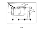
- 3103 Is expected as the next area.
- the moving distance or moving direction of the area is not expected, so for example, 3104 with a predetermined margin around 3103 as the expected range of the next area is assumed as the predicted range of the next area. From the range, the upper limit value and lower limit value of each parameter can be determined.
- the matching based on the prediction may be aborted, and the matching may be switched to the matching for the entire view image.
- step 2106 when the work target exists outside the range of the visual field image, the direction in which the work target is present may be superimposed on the visual field image.
- the region on the whole view image corresponding to the view image is a region that partially protrudes from the whole view image and the work target does not exist in the view image
- the positional relationship between the view image and the view image has already been obtained in step 2105. Therefore, by obtaining the direction of the work object viewed from the center coordinates of the field-of-view image, it is possible to indicate the relative direction in which the work object exists using arrows or the like as shown in FIG. is there.
- the panoramic image 2302 is converted around the visual field image 2301 in step 2105. Thereafter, an arrow 3203 indicating the direction in which the work target 3201 is present when viewed from the center coordinates of the visual field image 2301 may be superimposed on the visual field image 2301.
- the operator's finger can be used as a method for determining whether or not the selected work item is completed.
- the worker causes the work target area and the finger to be overlapped in the visual field image.
- the hand region can be easily extracted by detecting only the skin color region from the image, for example. If gloves are worn, the region may be extracted using the color of the gloves as a clue.
- the finger area is determined from the width of the extracted area, and the position of the tip of the finger is specified.
- the overlap between the extracted finger area and the work target area is determined on the field of view image. For example, if the overlap area size and the overlap time are equal to or greater than a predetermined threshold, It can be determined that the work has been completed.
- the overlap between the work target and the finger can also be determined by the overlap between the work target and the entire hand. If there are a plurality of work targets corresponding to the selected work item, the same process may be performed for all the corresponding work targets.
- the work target region to be determined next whether or not the work is completed is indicated on the field-of-view image by a superimposed display.
- the completed work target area can be erased from the view image, and only the uncompleted work target area can be superimposed on the view image.
- the color and shape of both ends are set to different colors and shapes, so that when one end is overlapped with the work target area, it represents the completion of the work on the work target and the other end When the edge is overlapped with the work target area, it is possible to superimpose and display the details of the work target on the visual field image.
- FIG. 20 shows an example of equipment that is a work area in which a plurality of full-view images are displayed.
- the equipment shown in FIG. 20 is different from the equipment shown in FIG. 2 in that a door 3901 is installed at the center. Further, a work target 3902 exists also inside the door.
- the whole-view image as shown in FIG. 21, two images are used: an image 4001 obtained by photographing the entire work area with the door closed, and an image 4002 obtained by photographing the interior with the door opened. To do. Further, as shown in FIG.
- the correspondence between 4001 and 4002 is represented by the correspondence between rectangles 4003 and 4004 indicating the door area.
- the reason why the door area is used for the association is that the association between the areas is clear and easy to set. Four or more points can be used.
- FIG. 22 shows a format for storing information representing the correspondence relationship between the panoramic images.
- Reference numeral 4101 denotes a file name of the panoramic image serving as the correspondence source
- numeral 4102 denotes a column of vertex coordinates representing an area on the panoramic image serving as the correspondence source.
- Reference numeral 4103 denotes a file name of a panoramic image as a correspondence destination
- reference numeral 4104 denotes a column of vertex coordinates representing an area on the panoramic image as a correspondence destination.
- the matching of the visual field image and the panoramic image in the processing of the work support control program 106 basically, all related panoramic images and the visual field image are matched, and the panoramic image having the highest similarity with the visual field image. And an area corresponding to the field-of-view image on the image.
- the range of the panoramic image to be matched with the field-of-view image can be limited by using the history. For example, when the region of the whole-view image corresponding to the field-of-view image includes the region of the door 4003, matching between the field-of-view image and the whole-view image targets both the images of the whole-view images 4001 and 4002 in FIG. . On the other hand, if the expected area does not include the door area, only the panoramic image 4001 needs to be used.
- the work area is long in the horizontal direction or the vertical direction, it is difficult to photograph the entire work area. Therefore, an image including a part of the work area and a portion overlapping each other is photographed, and the correspondence relationship between the images. Save with. In this case, an image that does not include an overlapping portion can also be used as the panoramic image.
- the work target is registered with the same name for all the panoramic images including them.
- the matching between the field-of-view image and the whole-view image is performed by using a method similar to the above-described method. It is possible to obtain the positional relationship, specify the position and object of the visual field image, and superimpose and display information necessary for work on the visual field image.
- the panoramic image corresponding to the field-of-view image is specified based only on the similarity obtained as a result of matching. For example, it is easy to distinguish from each other and to distinguish from the work target.
- a marker consisting of a color, shape, and pattern is placed on the work area, information indicating the correspondence between the marker and the panoramic image is stored, and the visual field image is supported by detecting these markers from the visual field image.
- a panoramic image to be specified may be specified.
- a single marker may be included in a single panoramic image, and a plurality of markers may be included. The marker may be placed at any location, but it is possible to efficiently switch the entire view image by installing it near the work target in the initial stage of the work performed on each view image.
- a general method used in image recognition technology can be used to detect a marker on a visual field image. For example, a marker image is prepared as a template, and the marker on the visual field image can be detected by matching the template with the visual field image.
- the camera 202 is used as the input device 102 and the monitor 205 of the HMD 203 and the portable computer 204 is used as the output device.
- the portable computer 204 equipped with a display unit is used. You can also. It is assumed that the portable computer is equipped with a display device 205 integrated with a touch panel as input means. Thereby, the operator can input to the computer directly on the screen with a finger or a pen.
- the back of the portable computer that is, the surface opposite to the display unit is equipped with a camera, and the portable computer is positioned with respect to the work area with the display unit of the portable computer facing the operator. By holding the image, the image of the work area is acquired by the camera and displayed on the display unit.
- an image acquired from a camera installed on the back of the portable computer is processed as a visual field image.
- the processing performed by the work information registration program 105 and the work support control program 106 is the same as the contents described above.
- the work support control program 106 determines that each work item has been completed due to the difference between the input device and the output device, that is, in the determination performed in step 2108 in FIG.
- Different operation methods can be used. Hereinafter, an operation method different from the above will be described.
- an image similar to that shown in FIG. 17 is displayed on the HMD, a list of work items is displayed on the screen of the portable computer, and the contents of this list are checked.
- the configuration is such that the worker notifies the work support control program of the completion of each work item.
- only a portable computer is used, only one display device can be used by the worker. If the image and the list of work items are displayed at the same time, the visibility of the screen may be reduced. Therefore, in this case, information related to the work item and the work target area are displayed in a superimposed manner, and a check field for notifying the completion of the work item is provided at the work item display location.
- the worker can notify the work support control program of the completion of the displayed work item by tapping the displayed check column with the operator's finger or pen.
- the completion of work is notified for each work target by superimposing the operator's fingers, hands, or special tools on the view image for the work target related to the selected work item. It was also possible to use this method.
- this operation can be performed by tapping the work target area superimposed on the screen with a finger or a pen.
- the work support control program determines that the work on the tapped work target is completed, and displays the next work target area in a superimposed manner. It is also possible to display the details of the work target in a superimposed manner by, for example, double-tapping (tapping twice in succession) the area to be worked on or pressing the screen for a while.
- the work support terminal described in the present embodiment includes a field of view camera that captures the worker's field of view, a first image captured by the field of view camera, and a plurality of objects to be worked.
- the second image is reflected in the first image by determining the correspondence between the first image and the second image, and a storage unit that stores information about the object.
- An image processing unit that identifies the target object; and a display unit that displays information about the target object in the first image. It is characterized by the whole being reflected.
- the work target is specified even if the work target in the field-of-view image is partially missing. be able to. Therefore, it is possible to smoothly perform work support without re-taking the field-of-view image many times.
- the field-of-view image and the panoramic image are two-dimensional information, the time and memory required for the image processing can be greatly reduced as compared with the case where image processing is performed based on the three-dimensional information.
- a second embodiment of the present invention will be described with reference to FIG.
- work performed by the work information management terminal (information processing apparatus) connected to the work support terminal via the network such as image processing and panoramic image registration performed by the work support terminal of the first embodiment.
- This is a support system and can provide the same effects as those of the first embodiment.
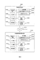
- FIG. 24 is a block diagram when the work support terminal according to the second embodiment of the present invention is realized on a commonly used computer, and the components of the work support terminal according to the first embodiment shown in FIG. Are separated into a worker terminal 5301 and a work information management terminal 5312, and the worker terminal 5301 and the work information management terminal 5312 are connected via a network 5311.
- An operator terminal 5301 in FIG. 24 includes an information processing apparatus 5302 for executing various programs, a camera for capturing a field-of-view image and inputting it as an image, and a mouse for giving instructions to the various programs by the operator.
- an input device 5303 including a touch panel, an output device 5304 using a monitor of a portable computer or an HMD, a communication device 5305 for exchanging information with the work information management terminal 5312, and various programs are stored.
- Storage device 5306 an image storage unit 5309 that is an image obtained by photographing the entire view of the work area where the worker performs the work, and information related to the work target defined on the full-view image that is information necessary for the support of the worker
- a work information storage unit 5310 that stores information on work procedures.
- the storage device 5306 also includes a work support control program 5307 for superimposing and displaying information for assisting the worker on the view image based on the result of matching the view image and the panoramic image, and a work information management terminal 5312.
- a transmission / reception program 5308 for exchanging information with the user is included.
- the work information management terminal 5312 includes an information processing device 5313 for executing various programs, a camera for inputting a panoramic image that is an image of a panoramic view of a work area where the worker performs work, Input / output device 5314 such as a keyboard, a mouse, a touch pad, etc.
- An output device 5315 such as a monitor or a speaker for displaying the screen of the user, a communication device 5316 for exchanging information with the operator terminal 5301, a storage device 5317 for storing various programs, and an operator
- An image storage unit 5320 that is an image obtained by capturing an entire view of the work area where the work is performed, and all the information that is necessary for supporting the worker.
- Work information storing section 5321 which stores information about the information and procedures relating to the work target defined on the image is included.
- the storage device 5317 is necessary for assisting the worker by defining the position and area of the work target in the real world, registering information to be presented to the worker, and setting the correspondence between them.
- a work information registration program 5318 which is a program for creating content, and a transmission / reception program 5319 for exchanging information between the worker terminal 5301 are included.
- the functions in the same components as those in the first embodiment shown in FIG. 1 are basically the same as the functions described in the first embodiment. is there. Furthermore, in the second embodiment, a function for exchanging information between the worker terminal 5301 and the work information management terminal 5312 is added to some components. Hereinafter, functions added in the second embodiment will be described.
- the worker terminal 5301 when information on a work procedure, a work target, and a panoramic image is not stored, the worker selects information on the work procedure related to the work to be performed at the start of the work. Since information related to available work procedures is stored in the work information management terminal 5312, the work support control program 5307 acquires a list of information related to work procedures from the work information management terminal 5312 using the transmission / reception program 5308. After that, a list of work procedures is displayed on the output device 5304. When information related to the work procedure corresponding to the work performed by the worker is selected, the result is transmitted from the worker terminal 5301 to the work information management terminal 5312 using the transmission / reception program 5308, and the work information management terminal 5312 selects the result.
- Information relating to the work procedure performed, information relating to the work object related thereto, and a panoramic image are extracted from the image storage unit 5320 and the work information storage unit 5321. Further, the extracted information is transmitted to the worker terminal 5301 using the transmission / reception program 5319, and the received panoramic image is received in the image storage unit 5309 in the worker terminal 5301, and information regarding the work procedure and the work target is obtained. It is stored in the work information storage unit 5310.
- the work support control program 5307 displays information related to the work being performed based on the result of matching the view images. The operator is supported by superimposing it on top.
- the worker's terminal image is transmitted to the work information management terminal, and the work information management terminal receives information on the worker's field of view image, information on the progress of the work, and the correspondence between the field image and the panoramic image.
- the contents may be displayed on the monitor.
- the visual field image may be displayed as it is on the work information management terminal as an image transmitted from the worker terminal.
- the same screen as in the first embodiment may be displayed on the work information management terminal. If the work information management terminal already stores information about work procedures, work objects, and panoramic images, only the information that identifies the work information, the work item for which work has been completed, and the work information number are displayed. It may be transmitted from the work terminal to the work information management terminal. If the work information management terminal does not store information about the work procedure or work object or the panoramic image, such information can be transmitted from the worker terminal to the work information management terminal.
- the work support system described in this embodiment is a field of view camera for photographing a worker's field of view, an image display unit, a first image photographed by the field of view camera, and a work target.
- a storage unit that stores information about the object, and the first image and the second image, the first image
- An information processing device connected to the terminal via a network, the information processing device comprising: an image processing unit that identifies the object in the image;
- the terminal transmits information related to the image and the object in the second image to the terminal, and the terminal that has received the second image is based on a matching result between the first image and the second image.
- Information received by the terminal Displayed on part, wherein the second image, characterized in that reflected their respective entireties of the object.
- the region corresponding to the field-of-view image on the whole-view image may be specified in real time, or the history of the field-of-view image region may be stored and You may make it display the locus
- the user of the work information management terminal can check the work status of the worker one by one.
Landscapes
- Engineering & Computer Science (AREA)
- Physics & Mathematics (AREA)
- Computer Hardware Design (AREA)
- General Physics & Mathematics (AREA)
- Theoretical Computer Science (AREA)
- Processing Or Creating Images (AREA)
- Image Analysis (AREA)
- Controls And Circuits For Display Device (AREA)
- Studio Devices (AREA)
Abstract
Description
図3に、作業情報登録プログラム105における全景画像および作業情報を登録する処理の流れを示す。まずステップ301において、作業領域の全景を表す全景画像を入力装置102の一つであるカメラにより取得、あるいはすでに画像記憶部107に格納されている全景画像から選択する。図2に示す構成では、カメラ202を用いて取得することができる。次にステップ302において、全景画像上における作業対象物の位置や領域を定義する。ここで、作業対象物とは、作業領域中に含まれるメータやスイッチ等、作業者が作業中に目視により確認、あるいは何らかの操作を行う対象物を指すものとする。さらにステップ303において、ステップ302で定義された作業対象に対してどのような順番でどのような作業を行うかを示す作業手順に関する情報を登録する。情報の登録が完了した全景画像は、画像記憶部107に格納される。図3に示す処理の流れでは、全景画像の登録301、作業対象の登録302および作業手順の登録303を順番に実行する形になっているが、すでに作業画像が登録された状態で作業対象の登録302から処理を開始すること、作業対象の登録までが完了した状態で作業手順の登録303から処理を開始すること、も可能である。
作業支援制御プログラム106の処理について説明する。



102 入力装置
103 出力装置
104 記憶装置
105 作業情報登録プログラム
106 作業支援制御プログラム
107 画像記憶部
108 作業情報記憶部
201 作業領域
202 カメラ
203 HMD(Head Mounted Display)
204 携帯型計算機
205 モニタおよびタッチパネル
5301 作業者用端末
5305 通信装置
5308 送受信プログラム
5311 ネットワーク
5312 作業情報管理用端末
5316 通信装置
5319 送受信プログラム
Claims (13)
- 作業者の視野を撮影する視野カメラと、
前記視野カメラで撮影された第1の画像と、付加情報を表示する対象となる対象物が写っている第2の画像と、前記付加情報とを記憶する記憶部と、
前記第1の画像と前記第2の画像との位置関係を求めることにより、前記第1の画像に写っている前記対象物を特定する画像処理部と、
前記第1の画像に写っている前記対象物についての付加情報を表示する表示部と、を有し、
前記第2の画像は、前記対象物が複数配置された作業領域を撮影した画像であることを特徴とする作業支援端末。 - 請求項1において、
前記第1の画像と前記第2の画像との位置関係は、前記第2の画像中の2次元座標で表されることを特徴とする作業支援端末。 - 請求項1において、
前記第1の画像中に前記対象物が写っていない場合には、前記画像処理部により求めた位置関係により、前記第1の画像から前記対象物への方向を示す矢印を表示することを特徴とする作業支援端末。 - 請求項1において、
前記表示部は前記第1の画像と前記付加情報とを重ねて表示することを特徴とする作業支援端末。 - 請求項1において、
前記作業支援端末は、入力装置をさらに有し、
前記入力装置に対し前記作業者の作業が開始されたことを示す入力があった場合に、前記視野カメラは前記第1の画像を撮影することを特徴とする作業支援端末。 - 請求項1において、
前記作業支援端末は、外部の情報処理装置と通信する手段をさらに有し、
前記記憶部には、さらに前記第1の画像を撮影した時刻が記憶されることを特徴とする作業支援端末。 - 作業者の視野を撮影する視野カメラと、画像表示部と、前記視野カメラで撮影された第1の画像と、付加情報を表示する対象となる対象物が写っている第2の画像と、前記付加情報とを記憶する記憶部と、前記第1の画像と前記第2の画像との位置関係を求めることにより、前記第1の画像に写っている前記対象物を特定する画像処理部とを具備する端末と、
前記端末とネットワークを介して接続される情報処理装置と、を有し、
前記情報処理装置は、前記第2の画像と前記第2の画像中の対象物についての付加情報を前記端末に送信し、
前記端末の前記画像表示部は、前記端末が受信した前記付加情報を表示し、
前記第2の画像は、前記対象物が複数配置された作業領域を撮影した画像であることを特徴とする作業支援システム。 - 請求項7において、
前記第1の画像と前記第2の画像との位置関係は、前記第2の画像中の2次元座標で表されることを特徴とする作業支援システム。 - 請求項8において、
前記第1の画像中に前記対象物が写っていない場合には、前記画像処理部により求めた位置関係により、前記第1の画像から前記対象物への方向を示す矢印を表示することを特徴とする作業支援システム。 - 請求項7において、
前記表示部は前記第1の画像と前記付加情報とを重ねて表示することを特徴とする作業支援システム。 - 請求項7において、
前記端末は、入力装置をさらに有し、
前記入力装置に対し前記作業者の作業が開始されたことを示す入力があった場合に、前記視野カメラは前記第1の画像を撮影することを特徴とする作業支援システム。 - 請求項7において、
前記端末は、外部の情報処理装置と通信する手段をさらに有し、
前記記憶部には、前記第1の画像と前記第1の画像を撮影した時刻と、が記憶され、
前記端末とネットワークを介して接続される情報処理装置に、前記第1の画像と前記時刻とを送信することを特徴とする作業支援システム。 - 作業者の視界である第1の画像を撮影する第1のステップと、
データベースに保持されている第2の画像と前記第1の画像との位置関係を求める第2のステップと、
前記第2のステップで求めた位置関係をもとに、前記第1の画像中に含まれ、付加情報を表示する対象となる対象物を特定する第3のステップと、
前記第3のステップで特定された前記対象物についての付加情報を読み出し、表示する第4のステップとを有し、
前記第2の画像は、前記対象物が複数配置された作業領域を撮影した画像であることを特徴とする作業支援方法。
Priority Applications (3)
| Application Number | Priority Date | Filing Date | Title |
|---|---|---|---|
| JP2014552805A JP6077010B2 (ja) | 2012-12-19 | 2012-12-19 | 作業支援端末および作業支援システム |
| BR112015013028A BR112015013028A2 (pt) | 2012-12-19 | 2012-12-19 | terminal, sistema e método de suporte de operação |
| PCT/JP2012/082860 WO2014097413A1 (ja) | 2012-12-19 | 2012-12-19 | 作業支援端末および作業支援システム |
Applications Claiming Priority (1)
| Application Number | Priority Date | Filing Date | Title |
|---|---|---|---|
| PCT/JP2012/082860 WO2014097413A1 (ja) | 2012-12-19 | 2012-12-19 | 作業支援端末および作業支援システム |
Publications (1)
| Publication Number | Publication Date |
|---|---|
| WO2014097413A1 true WO2014097413A1 (ja) | 2014-06-26 |
Family
ID=50977797
Family Applications (1)
| Application Number | Title | Priority Date | Filing Date |
|---|---|---|---|
| PCT/JP2012/082860 Ceased WO2014097413A1 (ja) | 2012-12-19 | 2012-12-19 | 作業支援端末および作業支援システム |
Country Status (3)
| Country | Link |
|---|---|
| JP (1) | JP6077010B2 (ja) |
| BR (1) | BR112015013028A2 (ja) |
| WO (1) | WO2014097413A1 (ja) |
Cited By (15)
| Publication number | Priority date | Publication date | Assignee | Title |
|---|---|---|---|---|
| JP2016138908A (ja) * | 2015-01-26 | 2016-08-04 | セイコーエプソン株式会社 | 表示システム、可搬型表示装置、表示制御装置、表示方法 |
| JP2017016056A (ja) * | 2015-07-06 | 2017-01-19 | セイコーエプソン株式会社 | 表示システム、表示装置、表示装置の制御方法、及び、プログラム |
| JP2017016599A (ja) * | 2015-07-07 | 2017-01-19 | セイコーエプソン株式会社 | 表示装置、表示装置の制御方法、及び、プログラム |
| JP2017091433A (ja) * | 2015-11-17 | 2017-05-25 | セイコーエプソン株式会社 | 頭部装着型表示装置、頭部装着型表示装置を制御する方法、コンピュータープログラム |
| WO2018158818A1 (ja) * | 2017-02-28 | 2018-09-07 | 日本電気株式会社 | 点検支援装置、点検支援方法および記録媒体 |
| WO2018158815A1 (ja) * | 2017-02-28 | 2018-09-07 | 日本電気株式会社 | 点検支援装置、点検支援方法および記録媒体 |
| JP2019061451A (ja) * | 2017-09-26 | 2019-04-18 | 株式会社キャプティ | 建築設備に関する情報の表示システム、表示装置およびプログラム |
| US10281976B2 (en) | 2015-07-07 | 2019-05-07 | Seiko Epson Corporation | Display device, control method for display device, and computer program |
| JP2020035280A (ja) * | 2018-08-31 | 2020-03-05 | 三菱電機株式会社 | 点検作業支援装置、点検作業支援システム、および点検作業支援方法 |
| JP2021082204A (ja) * | 2019-11-22 | 2021-05-27 | オムロン株式会社 | 作業指示システムおよび作業指示方法 |
| JP2021157781A (ja) * | 2020-03-27 | 2021-10-07 | Sppテクノロジーズ株式会社 | 保守作業支援システム、保守作業支援方法、および、保守作業支援プログラム |
| JP2023016589A (ja) * | 2021-07-21 | 2023-02-02 | 東芝デジタルエンジニアリング株式会社 | 点検作業順表示装置および点検作業支援システム |
| JP2023027650A (ja) * | 2021-08-17 | 2023-03-02 | 富士フイルムビジネスイノベーション株式会社 | 遠隔支援システム、端末装置、遠隔装置、誘導画像表示プログラム、及び遠隔支援プログラム |
| WO2023067836A1 (ja) * | 2021-10-18 | 2023-04-27 | 東芝デジタルソリューションズ株式会社 | コンテンツ表示装置、コンテンツ表示プログラム、コンテンツ表示方法、及びコンテンツ表示システム |
| JP2023060799A (ja) * | 2021-10-18 | 2023-04-28 | 東芝デジタルソリューションズ株式会社 | コンテンツ表示装置、コンテンツ表示プログラム、コンテンツ表示方法、及びコンテンツ表示システム |
Families Citing this family (1)
| Publication number | Priority date | Publication date | Assignee | Title |
|---|---|---|---|---|
| JP4745975B2 (ja) * | 2004-09-30 | 2011-08-10 | 富士フイルム株式会社 | 多層分析要素 |
Citations (2)
| Publication number | Priority date | Publication date | Assignee | Title |
|---|---|---|---|---|
| JP2006276748A (ja) * | 2005-03-30 | 2006-10-12 | Olympus Corp | 情報呈示装置、情報呈示方法、及びコンピュータプログラム |
| JP2011248748A (ja) * | 2010-05-28 | 2011-12-08 | Fujifilm Corp | 検査用携帯端末、検査システム、携帯端末用検査方法および携帯端末用検査プログラム |
Family Cites Families (9)
| Publication number | Priority date | Publication date | Assignee | Title |
|---|---|---|---|---|
| JP2002296010A (ja) * | 2001-03-29 | 2002-10-09 | Fujitsu Ltd | 画像を用いた自己位置同定方法 |
| JP2003281297A (ja) * | 2002-03-22 | 2003-10-03 | National Institute Of Advanced Industrial & Technology | 情報提示装置および情報提示方法 |
| JP2008201101A (ja) * | 2007-02-22 | 2008-09-04 | Kyocera Mita Corp | 操作案内表示装置 |
| JP5728159B2 (ja) * | 2010-02-02 | 2015-06-03 | ソニー株式会社 | 画像処理装置、画像処理方法及びプログラム |
| JP5682815B2 (ja) * | 2011-01-27 | 2015-03-11 | コニカミノルタ株式会社 | 情報処理装置、画像形成装置、およびプログラム |
| JP5707238B2 (ja) * | 2011-06-02 | 2015-04-22 | 株式会社日立製作所 | 画像検索装置及び画像検索システム |
| JP5837404B2 (ja) * | 2011-11-22 | 2015-12-24 | 株式会社日立製作所 | 画像処理装置、画像処理方法 |
| JP5837848B2 (ja) * | 2012-03-02 | 2015-12-24 | 株式会社日立製作所 | 画像処理装置、画像処理システム、画像処理方法 |
| JP2014056486A (ja) * | 2012-09-13 | 2014-03-27 | Hitachi Ltd | 画像ネットワークシステム、画像表示端末および画像処理方法 |
-
2012
- 2012-12-19 WO PCT/JP2012/082860 patent/WO2014097413A1/ja not_active Ceased
- 2012-12-19 JP JP2014552805A patent/JP6077010B2/ja not_active Expired - Fee Related
- 2012-12-19 BR BR112015013028A patent/BR112015013028A2/pt not_active Application Discontinuation
Patent Citations (2)
| Publication number | Priority date | Publication date | Assignee | Title |
|---|---|---|---|---|
| JP2006276748A (ja) * | 2005-03-30 | 2006-10-12 | Olympus Corp | 情報呈示装置、情報呈示方法、及びコンピュータプログラム |
| JP2011248748A (ja) * | 2010-05-28 | 2011-12-08 | Fujifilm Corp | 検査用携帯端末、検査システム、携帯端末用検査方法および携帯端末用検査プログラム |
Cited By (29)
| Publication number | Priority date | Publication date | Assignee | Title |
|---|---|---|---|---|
| JP2016138908A (ja) * | 2015-01-26 | 2016-08-04 | セイコーエプソン株式会社 | 表示システム、可搬型表示装置、表示制御装置、表示方法 |
| US10564919B2 (en) | 2015-07-06 | 2020-02-18 | Seiko Epson Corporation | Display system, display apparatus, method for controlling display apparatus, and program |
| JP2017016056A (ja) * | 2015-07-06 | 2017-01-19 | セイコーエプソン株式会社 | 表示システム、表示装置、表示装置の制御方法、及び、プログラム |
| US11073901B2 (en) | 2015-07-07 | 2021-07-27 | Seiko Epson Corporation | Display device, control method for display device, and computer program |
| US11301034B2 (en) | 2015-07-07 | 2022-04-12 | Seiko Epson Corporation | Display device, control method for display device, and computer program |
| JP2017016599A (ja) * | 2015-07-07 | 2017-01-19 | セイコーエプソン株式会社 | 表示装置、表示装置の制御方法、及び、プログラム |
| US10281976B2 (en) | 2015-07-07 | 2019-05-07 | Seiko Epson Corporation | Display device, control method for display device, and computer program |
| US10664044B2 (en) | 2015-07-07 | 2020-05-26 | Seiko Epson Corporation | Display device, control method for display device, and computer program |
| JP2017091433A (ja) * | 2015-11-17 | 2017-05-25 | セイコーエプソン株式会社 | 頭部装着型表示装置、頭部装着型表示装置を制御する方法、コンピュータープログラム |
| US11232530B2 (en) | 2017-02-28 | 2022-01-25 | Nec Corporation | Inspection assistance device, inspection assistance method, and recording medium |
| WO2018158818A1 (ja) * | 2017-02-28 | 2018-09-07 | 日本電気株式会社 | 点検支援装置、点検支援方法および記録媒体 |
| JP7111694B2 (ja) | 2017-02-28 | 2022-08-02 | 日本電気株式会社 | 点検支援装置、点検支援方法およびプログラム |
| JPWO2018158818A1 (ja) * | 2017-02-28 | 2019-12-12 | 日本電気株式会社 | 点検支援装置、点検支援方法およびプログラム |
| WO2018158815A1 (ja) * | 2017-02-28 | 2018-09-07 | 日本電気株式会社 | 点検支援装置、点検支援方法および記録媒体 |
| JPWO2018158815A1 (ja) * | 2017-02-28 | 2019-12-12 | 日本電気株式会社 | 点検支援装置、点検支援方法およびプログラム |
| JP2019061451A (ja) * | 2017-09-26 | 2019-04-18 | 株式会社キャプティ | 建築設備に関する情報の表示システム、表示装置およびプログラム |
| JP2020035280A (ja) * | 2018-08-31 | 2020-03-05 | 三菱電機株式会社 | 点検作業支援装置、点検作業支援システム、および点検作業支援方法 |
| JP7113702B2 (ja) | 2018-08-31 | 2022-08-05 | 三菱電機株式会社 | 点検作業支援装置、点検作業支援システム、および点検作業支援方法 |
| JP7395988B2 (ja) | 2019-11-22 | 2023-12-12 | オムロン株式会社 | 作業指示システムおよび作業指示方法 |
| JP2021082204A (ja) * | 2019-11-22 | 2021-05-27 | オムロン株式会社 | 作業指示システムおよび作業指示方法 |
| JP7149354B2 (ja) | 2020-03-27 | 2022-10-06 | Sppテクノロジーズ株式会社 | 保守作業支援システム、保守作業支援方法、および、保守作業支援プログラム |
| JP2021157781A (ja) * | 2020-03-27 | 2021-10-07 | Sppテクノロジーズ株式会社 | 保守作業支援システム、保守作業支援方法、および、保守作業支援プログラム |
| JP2023016589A (ja) * | 2021-07-21 | 2023-02-02 | 東芝デジタルエンジニアリング株式会社 | 点検作業順表示装置および点検作業支援システム |
| JP7410417B2 (ja) | 2021-07-21 | 2024-01-10 | 東芝デジタルエンジニアリング株式会社 | 点検作業順表示装置および点検作業支援システム |
| JP2023027650A (ja) * | 2021-08-17 | 2023-03-02 | 富士フイルムビジネスイノベーション株式会社 | 遠隔支援システム、端末装置、遠隔装置、誘導画像表示プログラム、及び遠隔支援プログラム |
| JP7746728B2 (ja) | 2021-08-17 | 2025-10-01 | 富士フイルムビジネスイノベーション株式会社 | 遠隔支援システム、端末装置、遠隔装置、誘導画像表示プログラム、及び遠隔支援プログラム |
| JP7330323B2 (ja) | 2021-10-18 | 2023-08-21 | 東芝デジタルソリューションズ株式会社 | コンテンツ表示装置、コンテンツ表示プログラム、コンテンツ表示方法、及びコンテンツ表示システム |
| JP2023060799A (ja) * | 2021-10-18 | 2023-04-28 | 東芝デジタルソリューションズ株式会社 | コンテンツ表示装置、コンテンツ表示プログラム、コンテンツ表示方法、及びコンテンツ表示システム |
| WO2023067836A1 (ja) * | 2021-10-18 | 2023-04-27 | 東芝デジタルソリューションズ株式会社 | コンテンツ表示装置、コンテンツ表示プログラム、コンテンツ表示方法、及びコンテンツ表示システム |
Also Published As
| Publication number | Publication date |
|---|---|
| BR112015013028A2 (pt) | 2017-07-11 |
| JPWO2014097413A1 (ja) | 2017-01-12 |
| JP6077010B2 (ja) | 2017-02-08 |
Similar Documents
| Publication | Publication Date | Title |
|---|---|---|
| JP6077010B2 (ja) | 作業支援端末および作業支援システム | |
| JP5762892B2 (ja) | 情報表示システム、情報表示方法、及び情報表示用プログラム | |
| CN105745586B (zh) | 作业辅助用数据生成程序 | |
| CN102473068B (zh) | 信息处理器、处理方法和程序 | |
| JP4137078B2 (ja) | 複合現実感情報生成装置および方法 | |
| US20090021475A1 (en) | Method for displaying and/or processing image data of medical origin using gesture recognition | |
| CN108027654B (zh) | 输入设备、输入方法和程序 | |
| JP2007531004A5 (ja) | ||
| CN109584374A (zh) | 用于使用可移动引导标记来提供交互导航辅助的方法、装置和计算机可读存储介质 | |
| CN101739722B (zh) | 信息处理装置和信息处理系统 | |
| TWI423075B (zh) | Information processing apparatus, and information processing method, and program | |
| JPWO2018025825A1 (ja) | 撮像システム | |
| CN112667179A (zh) | 一种基于混合现实的远程同步协作系统 | |
| WO2016084142A1 (ja) | 作業支援システム、及び、作業支援方法 | |
| JP2023082923A (ja) | 作業支援システム、作業対象特定装置および方法 | |
| JP7065795B2 (ja) | データ作成システム及びデータ作成方法 | |
| JP2007233971A (ja) | 画像合成方法及び装置 | |
| JP5525497B2 (ja) | プラント作業支援装置およびプラント作業支援方法 | |
| JP7531804B2 (ja) | 拡張現実表示システム | |
| JP7098473B2 (ja) | 画像処理装置、及び画像処理方法 | |
| JP7000513B1 (ja) | 構造物管理業務支援システム | |
| JP7640427B2 (ja) | 注視位置分析システム及び注視位置分析方法 | |
| WO2005096130A1 (ja) | 撮像装置の指示位置検出方法および装置、撮像装置の指示位置検出用プログラム | |
| JP7471570B2 (ja) | 建物構造物診断システム | |
| JP2005018385A (ja) | 作業情報提供装置 |
Legal Events
| Date | Code | Title | Description |
|---|---|---|---|
| 121 | Ep: the epo has been informed by wipo that ep was designated in this application |
Ref document number: 12890169 Country of ref document: EP Kind code of ref document: A1 |
|
| ENP | Entry into the national phase |
Ref document number: 2014552805 Country of ref document: JP Kind code of ref document: A |
|
| REG | Reference to national code |
Ref country code: BR Ref legal event code: B01A Ref document number: 112015013028 Country of ref document: BR |
|
| NENP | Non-entry into the national phase |
Ref country code: DE |
|
| 122 | Ep: pct application non-entry in european phase |
Ref document number: 12890169 Country of ref document: EP Kind code of ref document: A1 |
|
| ENP | Entry into the national phase |
Ref document number: 112015013028 Country of ref document: BR Kind code of ref document: A2 Effective date: 20150603 |