WO2014097405A1 - 表示装置、ナビゲーション装置、表示方法及びプログラム - Google Patents
表示装置、ナビゲーション装置、表示方法及びプログラム Download PDFInfo
- Publication number
- WO2014097405A1 WO2014097405A1 PCT/JP2012/082829 JP2012082829W WO2014097405A1 WO 2014097405 A1 WO2014097405 A1 WO 2014097405A1 JP 2012082829 W JP2012082829 W JP 2012082829W WO 2014097405 A1 WO2014097405 A1 WO 2014097405A1
- Authority
- WO
- WIPO (PCT)
- Prior art keywords
- display
- facility
- mark
- current position
- stopped
- Prior art date
- Legal status (The legal status is an assumption and is not a legal conclusion. Google has not performed a legal analysis and makes no representation as to the accuracy of the status listed.)
- Ceased
Links
Images


Classifications
-
- G—PHYSICS
- G01—MEASURING; TESTING
- G01C—MEASURING DISTANCES, LEVELS OR BEARINGS; SURVEYING; NAVIGATION; GYROSCOPIC INSTRUMENTS; PHOTOGRAMMETRY OR VIDEOGRAMMETRY
- G01C21/00—Navigation; Navigational instruments not provided for in groups G01C1/00 - G01C19/00
- G01C21/26—Navigation; Navigational instruments not provided for in groups G01C1/00 - G01C19/00 specially adapted for navigation in a road network
- G01C21/34—Route searching; Route guidance
- G01C21/36—Input/output arrangements for on-board computers
- G01C21/3679—Retrieval, searching and output of POI information, e.g. hotels, restaurants, shops, filling stations, parking facilities
- G01C21/3682—Retrieval, searching and output of POI information, e.g. hotels, restaurants, shops, filling stations, parking facilities output of POI information on a road map
Definitions
- the present invention relates to a technical field for displaying a mark indicating a facility.
- Patent Document 1 This type of technology is proposed in Patent Document 1, for example.
- Patent Document 1 in order to improve the visibility of the navigation screen, the logo mark of the facility near the running road is switched between display and non-display based on the frequency of vehicles visiting the facility in the past. Has been proposed.
- a logo mark of a facility that the user has not visited in the past may be hidden by lowering the display priority. Since such a facility may be used by a user, a logo mark may be displayed. On the other hand, for example, a facility of the same type as the facility where the user stopped by is unlikely to be used for a while after the stop, so improving the visibility of the screen by hiding the logo mark. It is considered effective.
- the main object of the present invention is to provide a display device that can appropriately control the display and non-display of a mark indicating a facility in consideration of the possibility of a user using the facility.
- the display device that moves together with the moving body includes: a display unit that displays a mark indicating a facility around a current position of the moving body; and a display control unit that controls display of the display unit.
- the display control means is of the same kind as (i) a facility where the mobile object has stopped within a predetermined time in the past from the current time, or (ii) a facility where the mobile object has stopped within a predetermined distance from the current position.
- the facility mark is not displayed on the display means.
- the navigation device that moves together with the moving body includes destination setting means for setting a destination, display means for displaying a mark indicating a facility around the current position of the moving body, Display control means for controlling the display of the display means, the display control means comprising: (i) a facility where the mobile object has stopped within a predetermined time in the past from the current time; and (ii) the mobile object is currently located.
- a mark of a facility of the same type as any one of a facility that has stopped within a predetermined distance from (iii) a facility set at the destination is not displayed on the display means.
- the display method executed by the display device that moves together with the moving body and displays a mark indicating a facility around the current position of the moving body is displayed on the display means.
- the display control step includes: (i) a facility where the mobile object has stopped within a predetermined time in the past from the current time; or (ii) the mobile object within a predetermined distance from the current position.
- the display means does not display the mark of the facility of the same kind as the facility that visited.
- a program executed by a display device that moves together with the moving object and displays a mark indicating a facility around the current position of the moving object and a computer is provided on the display means.
- the computer is caused to function as display control means for controlling display, and the display control means includes: (i) a facility where the mobile object has stopped within a predetermined time in the past from the current time, or (ii) the mobile object is currently located A mark of a facility of the same kind as a facility that has stopped within a predetermined distance is not displayed on the display means.
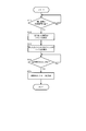
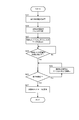
- FIG. 1 shows a schematic configuration of a navigation device according to the present embodiment. It is a flowchart which shows the display control method which concerns on 1st Example. It is a flowchart which shows the display control method which concerns on 2nd Example. It is a schematic block diagram of a head-up display.
- a display device that moves together with a moving body includes: a display unit that displays a mark indicating a facility around a current position of the moving body; and a display control unit that controls display of the display unit.
- the display control means is of the same kind as (i) a facility where the mobile object has stopped within a predetermined time in the past from the current time, or (ii) a facility where the mobile object has stopped within a predetermined distance from the current position.
- the facility mark is not displayed on the display means.
- the above display device shows a mark of a facility of the same type as the facility where the moving body stopped, for a while after the stop (until a predetermined time elapses after the stop or until the moving body travels a predetermined distance after the stop) And control to hide. That is, in such a period, the mark of the facility of the same type as the facility where the moving body stopped is not displayed, and only the mark of the facility of a different type from the facility where the moving body stopped is displayed. Thereby, the mark of the facility with a low possibility of being used by the user can be appropriately hidden and the visibility of the display screen can be improved. That is, according to the above display device, it is possible to improve the visibility of the display screen while maintaining the display of the mark of the facility that the user may use (that is, the mark desirably displayed). It becomes possible.
- the display control unit changes (i) the predetermined time or (ii) the predetermined distance according to the type of facility where the moving body has stopped. Thereby, a mark can be hidden during a period according to the type of facility.
- the display device further includes (i) the predetermined time or (ii) setting means for setting the predetermined distance for each type of facility, and the display control means includes the setting means.
- the predetermined time or (ii) the predetermined distance is changed in accordance with the setting according to. For example, the user can set a predetermined time or a predetermined distance for each type of facility.
- a head-up display can be used as the display means. According to the control by the above display control means, the number of marks to be displayed can be reduced, so that it is possible to appropriately secure the driver's front view in the head-up display.
- the display means can display the mark together with a map including a current position of the mobile object.
- the mark of the same kind of facility among the facilities visited within the distance and (iii) the facility set at the destination is not displayed on the display means.
- the display control unit is configured such that when the distance from the current position of the moving body to the destination is equal to or less than a predetermined distance, or from the current position of the moving body to the destination.
- the estimated required time is less than or equal to a predetermined time, all the marks other than the facility mark set at the destination are not displayed on the display means.
- all marks other than the facility mark set as the destination are hidden. Thereby, it becomes possible to make a user visually recognize the destination reliably.
- a display method executed by a display device that moves together with a mobile object and displays a mark indicating a facility around the current position of the mobile object is displayed on the display means.
- the display control step includes: (i) a facility where the mobile object has stopped within a predetermined time in the past from the current time; or (ii) the mobile object within a predetermined distance from the current position.
- the display means does not display the mark of the facility of the same type as the facility that visited.
- a program executed by a display device having a display unit and a computer that moves together with the mobile body and displays a mark indicating a facility around the current position of the mobile body is provided in the display unit.
- the computer is caused to function as display control means for controlling display, and the display control means includes: (i) a facility where the mobile object has stopped within a predetermined time in the past from the current time, or (ii) the mobile object is currently located
- the display means does not display the mark of the facility of the same kind as the facility that has stopped within a predetermined distance from the facility.
- the above program can be suitably handled in a state of being recorded on a recording medium.
- FIG. 1 shows a configuration of a navigation device 1 according to the present embodiment.
- the navigation device 1 can be, for example, a stationary navigation device installed in a vehicle, a portable navigation device (PND), or a mobile phone such as a smartphone.
- the navigation device 1 corresponds to an example of a “display device” in the present invention.
- the navigation device 1 mainly includes an independent positioning device 10, a GPS receiver 18, a system controller 20, a disk drive 31, a data storage unit 36, a communication interface 37, a communication device 38, and a display unit 40.
- the self-supporting positioning device 10 includes an acceleration sensor 11, an angular velocity sensor 12, and a distance sensor 13.
- the acceleration sensor 11 is made of, for example, a piezoelectric element, detects vehicle acceleration, and outputs acceleration data.
- the angular velocity sensor 12 is composed of, for example, a vibrating gyroscope, detects the angular velocity of the vehicle when the direction of the vehicle is changed, and outputs angular velocity data and relative azimuth data.
- the distance sensor 13 measures a vehicle speed pulse composed of a pulse signal generated with the rotation of the vehicle wheel.
- the GPS receiver 18 receives radio waves 19 carrying downlink data including positioning data from a plurality of GPS satellites.
- the positioning data is used to detect the absolute position (current position) of the vehicle from latitude and longitude information.
- the current position used in various controls and processes is not limited to using the value acquired from the GPS receiver 18, but the value acquired from the GPS receiver 18 and / or acquired from the autonomous positioning device 10. A value obtained based on the obtained value may be used.
- the system controller 20 includes an interface 21, a CPU (Central Processing Unit) 22, a ROM (Read Only Memory) 23, and a RAM (Random Access Memory) 24, and controls the entire navigation device 1.
- a CPU Central Processing Unit
- ROM Read Only Memory
- RAM Random Access Memory
- the interface 21 performs an interface operation with the acceleration sensor 11, the angular velocity sensor 12, the distance sensor 13, and the GPS receiver 18. From these, vehicle speed pulses, acceleration data, relative azimuth data, angular velocity data, GPS positioning data, absolute azimuth data, and the like are input to the system controller 20.
- the CPU 22 controls the entire system controller 20. For example, the CPU 22 obtains a guidance route (guidance route) to the destination based on the map data stored in the data storage unit 36, and performs route guidance based on the guidance route. Details of processing and control performed by the CPU 22 in this embodiment will be described later.
- the ROM 23 includes a nonvolatile memory (not shown) in which a control program for controlling the system controller 20 is stored.
- the RAM 24 stores various data such as route data preset by the user via the input device 60 so as to be readable, and provides a working area to the CPU 22.
- a system controller 20 a disk drive 31 such as a CD-ROM drive or a DVD-ROM drive, a data storage unit 36, a communication interface 37, a display unit 40, an audio output unit 50 and an input device 60 are mutually connected via a bus line 30. It is connected to the.
- the disk drive 31 reads and outputs content data such as music data and video data from a disk 33 such as a CD or DVD under the control of the system controller 20.
- the disk drive 31 may be either a CD-ROM drive or a DVD-ROM drive, or may be a CD and DVD compatible drive.
- the data storage unit 36 is configured by, for example, an HDD or the like, and is a unit that stores map data and the like.
- the map data includes link data, node data, facility data, and the like.
- the position (position coordinates) of the facility, the genre of the facility, a mark assigned to the genre of the facility, and the like can be cited.
- the genre of the facility includes a convenience store and a gas station, and the mark represents the genre and characteristics of the facility such as a convenience store and a gas station with characters and graphics.
- a genre of the facility a genre further subdivided for each type of store such as a convenience store or a gas station may be used, and in that case, a mark for each type of store may be used.
- the communication device 38 includes, for example, an FM tuner, a beacon receiver, a mobile phone, a dedicated communication card, and the like, and receives various types of information.
- the interface 37 performs an interface operation of the communication device 38 and inputs information received by the communication device 38 to the system controller 20 or the like.
- the display unit 40 displays various display data on a display unit such as a display under the control of the system controller 20. Specifically, the system controller 20 reads map data from the data storage unit 36. The display unit 40 displays a map image or the like corresponding to the map data read from the data storage unit 36 by the system controller 20 on the display screen.
- the display unit 40 includes a graphic controller 41 that controls the entire display unit 40 based on control data sent from the CPU 22 via the bus line 30, and image information that can be displayed immediately, such as a VRAM (Video) RAM) memory.
- a buffer memory 42 that temporarily stores, a display control unit 43 that controls display of a display 44 such as a liquid crystal based on image data output from the graphic controller 41, and a display 44 are provided.
- the display 44 is composed of, for example, a liquid crystal display device having a diagonal size of about 5 to 10 inches, and is mounted near the front panel in the vehicle.
- the display unit 40 corresponds to an example of “display means” in the present invention.
- the audio output unit 50 performs D / A (Digital-to-Analog) conversion of audio digital data sent from the CD-ROM drive 31, DVD-ROM 32, RAM 24, or the like via the bus line 30 under the control of the system controller 20.
- a D / A converter 51 to perform an amplifier (AMP) 52 that amplifies the audio analog signal output from the D / A converter 51, and a speaker 53 that converts the amplified audio analog signal into sound and outputs the sound into the vehicle. It is prepared for.
- AMP amplifier
- the input device 60 includes keys, switches, buttons, a remote controller, a voice input device, and the like for inputting various commands and data.
- the input device 60 is disposed around the front panel and the display 44 of the main body of the in-vehicle electronic system mounted in the vehicle.
- the display 44 is a touch panel system
- the touch panel provided on the display screen of the display 44 also functions as the input device 60.
- the CPU 22 controls the display 44 to display a map (map image) including the current position of the vehicle and a mark indicating a facility included in the map.
- the CPU 22 obtains the current position based on the value acquired from the GPS receiver 18 and / or the value acquired from the self-supporting positioning device 10, and the map data necessary for performing display according to the current position. Is obtained from the data storage unit 36 to perform such display control.
- the CPU 22 performs control to hide a mark indicating a facility that is unlikely to be used by the user. In other words, the CPU 22 performs control to display only marks indicating facilities that the user may use.
- the CPU 22 corresponds to an example of “display control means” in the present invention.
- the CPU 22 performs control to hide the mark of the facility of the same genre as the facility where the vehicle has stopped for a while after the stop. Specifically, the CPU 22 marks (i) a facility where the vehicle has stopped within a predetermined time in the past from the current time, or (ii) a facility where the vehicle has stopped within a predetermined distance from the current position, Is hidden.
- the CPU 22 hides all the convenience store marks. More specifically, in this example, when the vehicle resumes running after the vehicle stops at the convenience store, the CPU 22 hides all convenience store marks, and when a predetermined time elapses after resuming running or a predetermined distance. When traveling, all the convenience store marks that were hidden are displayed.
- This kind of display control is performed because it is unlikely that a facility of the same genre as the facility where the user has visited will be used for a while after the visit, and it is not necessary to display the mark. Because. In other words, if the mark of the facility of the same genre as the facility where the user stopped is hidden for a while after the stop, it is considered effective in improving the visibility of the display screen. .
- FIG. 2 is a flowchart showing the display control method according to the first embodiment. This flow is repeatedly executed by the CPU 22 in the navigation device 1. For example, the flow is executed at the start of traveling after the vehicle stops.
- step S11 the CPU 22 determines whether or not the vehicle has stopped at the same place for a predetermined time.
- the CPU 22 acquires the time measured by a sensor (which may be provided in the navigation device 1 or may be provided in a device different from the navigation device 1) that can measure the stop time of the vehicle. Then, the determination is performed.
- the CPU 22 determines that the vehicle has stopped at the facility at the place, and the process proceeds to step S12.
- step S11: No the process returns to step S11.
- step S12 the CPU 22 identifies the genre of the facility where the vehicle has stopped by referring to the map data (specifically, data related to the facility) stored in the data storage unit 36. Then, the process proceeds to step S13.
- map data specifically, data related to the facility
- step S13 the CPU 22 performs control to hide all the marks of facilities of the same genre as the genre specified in step S12. In other words, the CPU 22 performs control to display only the mark of the facility of a genre different from the genre specified in step S12. In this case, the CPU 22 performs control to display the mark by acquiring map data (for example, image data indicating the mark) stored in the data storage unit 36. Then, the process proceeds to step S14.
- map data for example, image data indicating the mark
- step S14 the CPU 22 determines whether or not it is a timing at which the display of the mark not displayed in step S13 may be permitted (hereinafter referred to as “display permission timing”).
- the CPU 22 travels a predetermined distance from the timing when a predetermined time has elapsed from the time when the mark is not displayed (corresponding to the time when the vehicle resumes running after the vehicle stops), or the time when the mark is not displayed. The determination is performed using the performed timing as the display permission timing.
- the predetermined time or the predetermined distance that defines such display permission timing may be set for each facility genre (in other words, the genre corresponding to the mark; the same shall apply hereinafter).
- “5 days” is set as a predetermined time for gas stations
- “6 hours” is set as a predetermined time for convenience stores
- “60 km” is set as a predetermined distance for service areas and parking areas. can do.
- the user may set a predetermined time or a predetermined distance that defines the display permission timing.
- the user may set a predetermined time or a predetermined distance for each genre of facility using the input device 60.
- the CPU 22 functions as “setting means” in the present invention, and applies a predetermined time or a predetermined distance set by the user.
- the presence / absence of mark display may be set for each genre of facilities. That is, depending on the genre of the facility, the mark may be set to be always displayed without switching between displaying and not displaying the mark as described above.
- step S14: Yes When it is the display permission timing (step S14: Yes), the CPU 22 displays the mark of the facility of the genre that has been hidden until then (step S15). Then, the process ends. On the other hand, when it is not the display permission timing (step S14: No), the process returns to step S14. In this case, the CPU 22 keeps the mark of the facility of the same genre as the genre specified in step S12 hidden.
- the mark of the facility of the same genre as the facility where the vehicle stopped is hidden, and only the mark of the facility of a genre different from the facility where the vehicle stopped is displayed.
- the mark of the facility with a low possibility of being used by the user can be appropriately hidden and the visibility of the display screen can be improved. That is, according to the first embodiment, it is possible to improve the visibility of the display screen while maintaining the display of the mark of the facility that the user may use (that is, the mark that is desirably displayed). It becomes possible.
- Second Example a display control method according to a second example will be described.
- the CPU 22 hides the mark of the facility of the same genre as the facility (however, the mark of the facility set as the destination is displayed). ). This is because it is considered that the user is unlikely to use other facilities of the same genre as the facility set as the destination while heading to the destination.
- the CPU 22 marks the facility set as the destination when the distance from the current position to the destination is equal to or less than a predetermined distance (that is, when the vehicle approaches the destination). Hide all marks except. That is, only the mark of the facility set as the destination is displayed. This is to make the user visually recognize the destination.
- the CPU 22 displays all the marks that have not been displayed so far. This is to make it easier for the user to select the next destination while saving the user from having to display the mark again.
- FIG. 3 is a flowchart showing a display control method according to the second embodiment. This flow is repeatedly executed by the CPU 22 in the navigation device 1. For example, the flow is executed when a facility is set as a destination by the user.
- step S21 the CPU 22 acquires data of a facility set as a destination.
- the CPU 22 refers to the map data (specifically, data relating to the facility) stored in the data storage unit 36. Then, the process proceeds to step S22.
- step S22 the CPU 22 identifies the genre of the destination facility acquired in step S21 by referring to the map data (specifically, data relating to the facility) stored in the data storage unit 36. Then, the process proceeds to step S23.
- map data specifically, data relating to the facility
- step S23 the CPU 22 performs control to hide all marks of facilities of the same genre as the genre specified in step S22. That is, the CPU 22 performs control to display only the facility mark set as the destination and the facility mark of a genre different from the genre identified in step S22. In this case, the CPU 22 performs control to display the mark by acquiring map data (for example, image data indicating the mark) stored in the data storage unit 36. Then, the process proceeds to step S24.
- map data for example, image data indicating the mark
- step S24 the CPU 22 determines whether or not the distance from the current position of the vehicle to the destination is equal to or less than a predetermined distance.
- the CPU 22 obtains the current position based on the value acquired from the GPS receiver 18 and / or the value acquired from the autonomous positioning device 10, and the route from the current position to the destination reaches the destination. This determination is made by obtaining along If the distance to the destination is equal to or smaller than the predetermined distance (step S24: Yes), the process proceeds to step S25. If the distance to the destination is not equal to or smaller than the predetermined distance (step S24: No), the process is performed. The process returns to step S24.
- step S25 the CPU 22 determines whether or not the vehicle has arrived at the destination. In this case, the CPU 22 performs the determination by comparing the current position obtained as described above with the position of the destination.
- step S26 If the vehicle has not arrived at the destination (step S25: No), the process proceeds to step S26.
- the situation where the process proceeds to step S26 is a situation where the distance to the destination is not more than the predetermined distance but has not yet arrived at the destination. That is, the vehicle is approaching the destination.
- the CPU 22 hides all marks other than the facility mark set as the destination (step S26). That is, the CPU 22 displays only the facility mark set as the destination. Then, the process returns to step S25.
- step S25 the process proceeds to step S27.
- step S27 the CPU 22 displays all the marks that have not been displayed so far. Then, the process ends.
- the mark of the facility of the same genre as the facility set as the destination is hidden, so that the mark of the facility that is unlikely to be used by the user is appropriately hidden. can do. Therefore, the visibility of the display screen can be improved. Also, according to the second embodiment, when the vehicle approaches the destination, all the marks other than the facility mark set as the destination are hidden so that the user can see the destination reliably. It becomes possible to make it.
- first embodiment and the second embodiment may be combined. That is, both the mark of the facility of the same genre as the facility where the vehicle stopped and the mark of the facility set as the destination and the facility of the same genre may be hidden.
- the combination of the first embodiment and the second embodiment can be suitably applied when the user stops at a facility on the way to the destination.
- the mark of the facility of the same genre as the facility where the vehicle stopped is switched from non-display to display when the display permission timing is reached. Alternatively, it may be switched from non-display to display when the vehicle arrives at the destination.
- the distance from the current position of the vehicle to the destination is equal to or less than a predetermined distance (see step S24 in FIG. 3). It may be determined whether or not the estimated required time to the destination is a predetermined time or less. In other words, when the estimated time from the current position of the vehicle to the destination is less than the predetermined time, it is determined that the vehicle has approached the destination and all marks other than the facility mark set as the destination are displayed. It may be hidden. In one example, the estimated required time is obtained from the distance from the current position to the destination, the speed limit of the road that forms the route from the current position to the destination, and the like.
- the present invention is not limited to being applied to the navigation device 1.
- the present invention can also be applied to a head-up display for visually recognizing a virtual image from the position (eye point) of the driver's eyes. That is, a head-up display may be applied as the “display unit” in the present invention.
- FIG. 4 is a schematic configuration diagram of the head-up display 2.
- the head-up display 2 includes a light source unit 3 and a combiner 9, and is attached to a vehicle including a front window 25, a ceiling portion 27, a bonnet 28, a dashboard 29, and the like.
- the light source unit 3 is installed on the ceiling 27 in the passenger compartment via the support members 5a and 5b, and emits light constituting an image to be displayed toward the combiner 9. Specifically, the light source unit 3 acquires an image (specifically, an image generated by display control by the CPU 22 in the navigation device 1) generated by the navigation device 1 described above, and light constituting the image. Is output to the combiner 9 to allow the driver to visually recognize the virtual image Iv through the combiner 9.
- the light source unit 3 has a light source such as a laser light source or an LCD light source, and emits light from the light source.
- the combiner 9 is configured as a half mirror.
- the combiner 9 projects the display image emitted from the light source unit 3 and reflects the display image as a virtual image Iv by reflecting the display image to the driver's eye point Pe.
- the combiner 9 has the support shaft part 8 installed in the ceiling part 27, and rotates the support shaft part 8 as a spindle.
- the support shaft portion 8 is installed, for example, in the vicinity of the ceiling portion 27 in the vicinity of the upper end of the front window 25, in other words, the position where a sun visor (not shown) for the driver is installed.
- the support shaft portion 8 may be installed instead of the above-described sun visor.
- Such a head-up display 2 displays an image superimposed on the actual scenery in the traveling direction of the vehicle. Therefore, in the head-up display 2, when a large number of marks are displayed, the driver's front view may be affected. Therefore, if the display control method according to the above-described embodiment is applied to such a head-up display 2, the number of displayed marks can be appropriately reduced. It is effective.
Landscapes
- Engineering & Computer Science (AREA)
- Radar, Positioning & Navigation (AREA)
- Remote Sensing (AREA)
- Automation & Control Theory (AREA)
- Physics & Mathematics (AREA)
- General Physics & Mathematics (AREA)
- Navigation (AREA)
Abstract
移動体と共に移動する表示装置は、移動体の現在位置周辺の施設を示すマークを表示する表示手段と、表示手段の表示を制御する表示制御手段と、を備える。表示制御手段は、(i)移動体が現在時刻から過去の所定時間内に立ち寄った施設、又は(ii)移動体が現在位置から所定距離内で立ち寄った施設、と同種の施設のマークを表示手段に表示させない。これにより、ユーザが利用する可能性が低い施設のマークを適切に非表示とすることができ、表示画面の視認性を向上させることが可能となる。
Description
本発明は、施設を示すマークを表示する技術分野に関する。
この種の技術が、例えば特許文献1に提案されている。特許文献1には、ナビゲーション画面の視認性を向上させるべく、走行している道路近傍の施設のロゴマークを、過去に当該施設を車両が訪れた頻度に基づいて表示と非表示とを切り替えることが提案されている。
上記した特許文献1に係る技術では、例えばユーザが過去に訪れたことのない施設のロゴマークが、表示優先度が下げられることで非表示にされる場合があった。そのような施設はユーザが利用する可能性があるため、ロゴマークを表示しても良いと考えられる。他方で、例えばユーザが立ち寄った施設と同種の施設などは、その立ち寄り後しばらくの間は利用される可能性が低いと言えるため、ロゴマークを非表示にすれば画面の視認性を向上させる上で効果的であると考えられる。
本発明が解決しようとする課題としては、上記のものが一例として挙げられる。本発明は、ユーザが施設を利用する可能性を考慮して、施設を示すマークの表示と非表示とを適切に制御することが可能な表示装置などを提供することを主な目的とする。
請求項に記載の発明では、移動体と共に移動する表示装置は、前記移動体の現在位置周辺の施設を示すマークを表示する表示手段と、前記表示手段の表示を制御する表示制御手段と、を備え、前記表示制御手段は、(i)前記移動体が現在時刻から過去の所定時間内に立ち寄った施設、又は(ii)前記移動体が現在位置から所定距離内で立ち寄った施設、と同種の施設のマークを前記表示手段に表示させないことを特徴とする。
また、請求項に記載の発明では、移動体と共に移動するナビゲーション装置は、目的地を設定する目的地設定手段と、前記移動体の現在位置周辺の施設を示すマークを表示する表示手段と、前記表示手段の表示を制御する表示制御手段と、を備え、前記表示制御手段は、(i)前記移動体が現在時刻から過去の所定時間内に立ち寄った施設、(ii)前記移動体が現在位置から所定距離内で立ち寄った施設、及び(iii)前記目的地に設定された施設、のうちのいずれかの施設と同種の施設のマークを前記表示手段に表示させないことを特徴とする。
また、請求項に記載の発明では、移動体と共に移動し、前記移動体の現在位置周辺の施設を示すマークを表示する表示手段を有する表示装置によって実行される表示方法は、前記表示手段の表示を制御する表示制御工程を備え、前記表示制御工程は、(i)前記移動体が現在時刻から過去の所定時間内に立ち寄った施設、又は(ii)前記移動体が現在位置から所定距離内で立ち寄った施設、と同種の施設のマークを前記表示手段に表示させないことを特徴とする。
また、請求項に記載の発明では、移動体と共に移動し、前記移動体の現在位置周辺の施設を示すマークを表示する表示手段及びコンピュータを有する表示装置によって実行されるプログラムは、前記表示手段の表示を制御する表示制御手段として前記コンピュータを機能させ、前記表示制御手段は、(i)前記移動体が現在時刻から過去の所定時間内に立ち寄った施設、又は(ii)前記移動体が現在位置から所定距離内で立ち寄った施設、と同種の施設のマークを前記表示手段に表示させないことを特徴とする。
本発明の1つの観点では、移動体と共に移動する表示装置は、前記移動体の現在位置周辺の施設を示すマークを表示する表示手段と、前記表示手段の表示を制御する表示制御手段と、を備え、前記表示制御手段は、(i)前記移動体が現在時刻から過去の所定時間内に立ち寄った施設、又は(ii)前記移動体が現在位置から所定距離内で立ち寄った施設、と同種の施設のマークを前記表示手段に表示させない。
上記の表示装置は、移動体が立ち寄った施設と同種の施設のマークを、立ち寄り後のしばらくの間(立ち寄り後から所定時間経過するまでの間、又は立ち寄り後に移動体が所定距離走行するまでの間)、非表示とする制御を行う。つまり、そのような期間において、移動体が立ち寄った施設と同種の施設のマークを非表示とし、移動体が立ち寄った施設とは異なる種類の施設のマークのみを表示させる。これにより、ユーザが利用する可能性が低い施設のマークを適切に非表示とすることができ、表示画面の視認性を向上させることが可能となる。つまり、上記の表示装置によれば、ユーザが利用する可能性がある施設のマーク(即ち表示しておくのが望ましいマーク)についての表示は維持しつつ、表示画面の視認性を向上させることが可能となる。
上記の表示装置の一態様では、前記表示制御手段は、前記移動体が立ち寄った施設の種別に応じて、(i)前記所定時間、又は(ii)前記所定距離を変化させる。これにより、施設の種別に応じた期間においてマークを非表示とすることができる。
上記の表示装置の他の一態様では、前記施設の種別ごとに、(i)前記所定時間、又は(ii)前記所定距離を設定する設定手段を更に備え、前記表示制御手段は、前記設定手段による設定に応じて、(i)前記所定時間、又は(ii)前記所定距離を変化させる。例えば、ユーザが、施設の種別ごとに所定時間又は所定距離を設定することができる。
上記の表示装置において好適には、前記表示手段として、ヘッドアップディスプレイを用いることができる。上記の表示制御手段による制御によれば表示されるマークの数を少なくすることができるため、ヘッドアップディスプレイにおいて運転者の前方視界を適切に確保することが可能となる。
また好適には、前記表示手段は、前記移動体の現在位置を含む地図と共に、前記マークを表示することができる。
本発明の他の観点では、移動体と共に移動するナビゲーション装置は、目的地を設定する目的地設定手段と、前記移動体の現在位置周辺の施設を示すマークを表示する表示手段と、前記表示手段の表示を制御する表示制御手段と、を備え、前記表示制御手段は、(i)前記移動体が現在時刻から過去の所定時間内に立ち寄った施設、(ii)前記移動体が現在位置から所定距離内で立ち寄った施設、及び(iii)前記目的地に設定された施設、のうちのいずれかの施設と同種の施設のマークを前記表示手段に表示させない。
上記の表示装置では、目的地として施設が設定されている場合に、その施設と同種の施設のマークを非表示とする制御を行う。これによっても、ユーザが利用する可能性が低い施設のマークを適切に非表示とすることができ、表示画面の視認性を向上させることが可能となる。
上記の表示装置の一態様では、前記表示制御手段は、前記移動体の現在位置から前記目的地までの距離が所定距離以下となった際、または前記移動体の現在位置から前記目的地までの予測所要時間が所定時間以下となった際に、前記目的地に設定された施設のマーク以外の全てのマークを前記表示手段に表示させない。この態様では、移動体が目的地に近付いた際に、目的地として設定された施設のマーク以外の全てのマークを非表示にする。これにより、ユーザに目的地を確実に視認させることが可能となる。
また、本発明の他の観点では、移動体と共に移動し、前記移動体の現在位置周辺の施設を示すマークを表示する表示手段を有する表示装置によって実行される表示方法は、前記表示手段の表示を制御する表示制御工程を備え、前記表示制御工程は、(i)前記移動体が現在時刻から過去の所定時間内に立ち寄った施設、又は(ii)前記移動体が現在位置から所定距離内で立ち寄った施設、と同種の施設のマークを前記表示手段に表示させない。
また、本発明の他の観点では、移動体と共に移動し、前記移動体の現在位置周辺の施設を示すマークを表示する表示手段及びコンピュータを有する表示装置によって実行されるプログラムは、前記表示手段の表示を制御する表示制御手段として前記コンピュータを機能させ、前記表示制御手段は、(i)前記移動体が現在時刻から過去の所定時間内に立ち寄った施設、又は(ii)前記移動体が現在位置から所定距離内で立ち寄った施設、と同種の施設のマークを前記表示手段に表示させない。
上記のプログラムは、記録媒体に記録した状態で好適に取り扱うことができる。
以下、図面を参照して本発明の好適な実施例について説明する。
1.装置構成
図1は、本実施例に係るナビゲーション装置1の構成を示す。ナビゲーション装置1は、例えば、車両に設置される据え置き型のナビゲーション装置や、PND(Portable Navigation Device)や、スマートフォンなどの携帯電話とすることができる。なお、ナビゲーション装置1は、本発明における「表示装置」の一例に相当する。
図1は、本実施例に係るナビゲーション装置1の構成を示す。ナビゲーション装置1は、例えば、車両に設置される据え置き型のナビゲーション装置や、PND(Portable Navigation Device)や、スマートフォンなどの携帯電話とすることができる。なお、ナビゲーション装置1は、本発明における「表示装置」の一例に相当する。
図1に示すように、ナビゲーション装置1は、主に、自立測位装置10、GPS受信機18、システムコントローラ20、ディスクドライブ31、データ記憶ユニット36、通信用インタフェース37、通信装置38、表示ユニット40、音声出力ユニット50、及び入力装置60を備える。
自立測位装置10は、加速度センサ11、角速度センサ12及び距離センサ13を備える。加速度センサ11は、例えば圧電素子からなり、車両の加速度を検出し、加速度データを出力する。角速度センサ12は、例えば振動ジャイロからなり、車両の方向変換時における車両の角速度を検出し、角速度データ及び相対方位データを出力する。距離センサ13は、車両の車輪の回転に伴って発生されているパルス信号からなる車速パルスを計測する。
GPS受信機18は、複数のGPS衛星から、測位用データを含む下り回線データを搬送する電波19を受信する。測位用データは、緯度及び経度情報等から車両の絶対的な位置(現在位置)を検出するために用いられる。なお、各種の制御や処理で用いる現在位置としては、GPS受信機18から取得された値を用いることに限定はされず、GPS受信機18から取得された値及び/又は自立測位装置10から取得された値に基づいて求めた値を用いても良い。
システムコントローラ20は、インタフェース21、CPU(Central Processing Unit)22、ROM(Read Only Memory)23及びRAM(Random Access Memory)24を含んでおり、ナビゲーション装置1全体の制御を行う。
インタフェース21は、加速度センサ11、角速度センサ12及び距離センサ13並びにGPS受信機18とのインタフェース動作を行う。そして、これらから、車速パルス、加速度データ、相対方位データ、角速度データ、GPS測位データ、絶対方位データ等をシステムコントローラ20に入力する。CPU22は、システムコントローラ20全体を制御する。例えば、CPU22は、データ記憶ユニット36に記憶された地図データなどに基づいて、目的地までの案内ルート(案内経路)を求め、その案内ルートに基づいてルート案内を行う。本実施例でCPU22が行う処理・制御については、詳細は後述する。ROM23は、システムコントローラ20を制御する制御プログラム等が格納された図示しない不揮発性メモリ等を有する。RAM24は、入力装置60を介して使用者により予め設定された経路データ等の各種データを読み出し可能に格納したり、CPU22に対してワーキングエリアを提供したりする。
システムコントローラ20、CD-ROMドライブ又はDVD-ROMドライブなどのディスクドライブ31、データ記憶ユニット36、通信用インタフェース37、表示ユニット40、音声出力ユニット50及び入力装置60は、バスライン30を介して相互に接続されている。
ディスクドライブ31は、システムコントローラ20の制御の下、CD又はDVDといったディスク33から、音楽データ、映像データなどのコンテンツデータを読み出し、出力する。なお、ディスクドライブ31は、CD-ROMドライブ又はDVD-ROMドライブのうち、いずれか一方としてもよいし、CD及びDVDコンパチブルのドライブとしてもよい。
データ記憶ユニット36は、例えばHDDなどにより構成され、地図データなどを記憶するユニットである。例えば、地図データには、リンクのデータや、ノードのデータや、施設に関するデータなどが含まれる。ここで、施設に関するデータとしては、施設の位置(位置座標)や、施設のジャンルや、施設のジャンルに割り当てられたマークなどが挙げられる。例えば、施設のジャンルとしてはコンビニエンスストアやガソリンスタンドなどが挙げられ、マークとはコンビニエンスストアやガソリンスタンドなどの施設のジャンルや特徴などを文字や図形などで表現したものである。なお、施設のジャンルとして、コンビニエンスストアやガソリンスタンドなどの店舗の種類ごとに更に細分化したジャンルを用いても良く、その場合には店舗の種類ごとのマークを用いても良い。
通信装置38は、例えば、FMチューナや、ビーコンレシーバや、携帯電話や、専用の通信カードなどにより構成され、各種情報を受信する。インタフェース37は、通信装置38のインタフェース動作を行い、通信装置38が受信した情報をシステムコントローラ20等に入力する。
表示ユニット40は、システムコントローラ20の制御の下、各種表示データをディスプレイなどの表示部に表示する。具体的には、システムコントローラ20は、データ記憶ユニット36から地図データを読み出す。表示ユニット40は、システムコントローラ20によってデータ記憶ユニット36から読み出された地図データに応じた地図画像などを表示画面上に表示する。表示ユニット40は、バスライン30を介してCPU22から送られる制御データに基づいて表示ユニット40全体の制御を行うグラフィックコントローラ41と、VRAM(Video RAM)等のメモリからなり即時表示可能な画像情報を一時的に記憶するバッファメモリ42と、グラフィックコントローラ41から出力される画像データに基づいて、液晶等のディスプレイ44を表示制御する表示制御部43と、ディスプレイ44とを備える。ディスプレイ44は、例えば対角5~10インチ程度の液晶表示装置等からなり、車内のフロントパネル付近に装着される。なお、表示ユニット40は、本発明における「表示手段」の一例に相当する。
音声出力ユニット50は、システムコントローラ20の制御の下、CD-ROMドライブ31又はDVD-ROM32、若しくはRAM24等からバスライン30を介して送られる音声デジタルデータのD/A(Digital to Analog)変換を行うD/Aコンバータ51と、D/Aコンバータ51から出力される音声アナログ信号を増幅する増幅器(AMP)52と、増幅された音声アナログ信号を音声に変換して車内に出力するスピーカ53とを備えて構成されている。
入力装置60は、各種コマンドやデータを入力するための、キー、スイッチ、ボタン、リモコン、音声入力装置等から構成されている。入力装置60は、車内に搭載された当該車載用電子システムの本体のフロントパネルやディスプレイ44の周囲に配置される。また、ディスプレイ44がタッチパネル方式の場合、ディスプレイ44の表示画面上に設けられたタッチパネルも入力装置60として機能する。
2.表示制御方法
次に、本実施例においてナビゲーション装置1内のCPU22が行う表示制御方法について説明する。基本的には、CPU22は、車両の現在位置を含む地図(地図画像)と、当該地図に含まれる施設を示すマークとを、ディスプレイ44に表示させる制御を行う。この場合、CPU22は、GPS受信機18から取得された値及び/又は自立測位装置10から取得された値に基づいて現在位置を求め、その現在位置に応じた表示を行うのに必要な地図データをデータ記憶ユニット36から取得することで、このような表示制御を行う。
次に、本実施例においてナビゲーション装置1内のCPU22が行う表示制御方法について説明する。基本的には、CPU22は、車両の現在位置を含む地図(地図画像)と、当該地図に含まれる施設を示すマークとを、ディスプレイ44に表示させる制御を行う。この場合、CPU22は、GPS受信機18から取得された値及び/又は自立測位装置10から取得された値に基づいて現在位置を求め、その現在位置に応じた表示を行うのに必要な地図データをデータ記憶ユニット36から取得することで、このような表示制御を行う。
本実施例においては、表示画面の視認性を向上させる観点から、表示しなくても良いと考えられるマークを非表示とする。具体的には、CPU22は、ユーザが利用する可能性が低い施設を示すマークを非表示とする制御を行う。言い換えると、CPU22は、ユーザが利用する可能性がある施設を示すマークのみを表示させる制御を行う。このように、CPU22は、本発明における「表示制御手段」の一例に相当する。
以下では、CPU22が行う表示制御方法の具体的な実施例(第1及び第2実施例)について説明する。
2-1.第1実施例
第1実施例では、CPU22は、車両が立ち寄った施設と同ジャンルの施設のマークを、立ち寄り後のしばらくの間は非表示とする制御を行う。具体的には、CPU22は、(i)車両が現在時刻から過去の所定時間内に立ち寄った施設、又は(ii)車両が現在位置から所定距離内で立ち寄った施設、と同ジャンルの施設のマークを非表示とする。1つの例では、車両がコンビニエンスストアに立ち寄った場合、CPU22は、全てのコンビニエンスストアのマークを非表示とする。より詳しくは、この例では、CPU22は、車両がコンビニエンスストアで停車した後に走行を再開した際に、全てのコンビニエンスストアのマークを非表示とし、そして、走行再開後に所定時間経過した際又は所定距離走行した際に、非表示としていたコンビニエンスストアのマークを全て表示させる。
第1実施例では、CPU22は、車両が立ち寄った施設と同ジャンルの施設のマークを、立ち寄り後のしばらくの間は非表示とする制御を行う。具体的には、CPU22は、(i)車両が現在時刻から過去の所定時間内に立ち寄った施設、又は(ii)車両が現在位置から所定距離内で立ち寄った施設、と同ジャンルの施設のマークを非表示とする。1つの例では、車両がコンビニエンスストアに立ち寄った場合、CPU22は、全てのコンビニエンスストアのマークを非表示とする。より詳しくは、この例では、CPU22は、車両がコンビニエンスストアで停車した後に走行を再開した際に、全てのコンビニエンスストアのマークを非表示とし、そして、走行再開後に所定時間経過した際又は所定距離走行した際に、非表示としていたコンビニエンスストアのマークを全て表示させる。
このような表示制御を行うのは、ユーザが立ち寄った施設と同ジャンルの施設は、その立ち寄り後しばらくの間は利用される可能性が低いと言え、マークを表示しなくても良いと考えられるからである。つまりは、ユーザが立ち寄った施設と同ジャンルの施設のマークを、その立ち寄り後しばらくの間は非表示にすれば、表示画面の視認性を向上させる上で効果的であると考えられるからである。
図2は、第1実施例に係る表示制御方法を示すフローチャートである。このフローは、ナビゲーション装置1内のCPU22によって繰り返し実行される。例えば、当該フローは、車両の停車後の走行開始時に実行される。
まず、ステップS11では、CPU22は、車両が同じ場所に所定時間停車していたか否かを判定する。ここでは、車両が同じ場所に所定時間停車していたか否かを判定することで、車両が施設に立ち寄ったか否かを判断している。1つの例では、CPU22は、車両の停車時間を計測可能なセンサ(ナビゲーション装置1内に設けても良いし、ナビゲーション装置1とは異なる装置に設けても良い)が計測した時間を取得することで、当該判定を行う。車両が同じ場所に所定時間停車していた場合(ステップS11:Yes)、CPU22は、その場所にある施設に車両が立ち寄っていたと判断し、処理はステップS12に進む。これに対して、車両が同じ場所に所定時間停車していなかった場合(ステップS11:No)、処理はステップS11に戻る。
ステップS12では、CPU22は、データ記憶ユニット36に記憶された地図データ(具体的には施設に関するデータ)を参照することで、車両が立ち寄った施設のジャンルを特定する。そして、処理はステップS13に進む。
ステップS13では、CPU22は、ステップS12で特定したジャンルと同ジャンルの施設のマークを全て非表示とする制御を行う。言い換えると、CPU22は、ステップS12で特定したジャンルとは異なるジャンルの施設のマークのみを表示させる制御を行う。この場合、CPU22は、データ記憶ユニット36に記憶された地図データ(例えばマークを示す画像データなど)を取得することで、マークを表示させる制御を行う。そして、処理はステップS14に進む。
ステップS14では、CPU22は、ステップS13で非表示としたマークの表示を許可して良いタイミング(以下では「表示許可タイミング」と呼ぶ。)であるか否かを判定する。CPU22は、マークを非表示とした時点(車両の停車後の走行再開時点に相当する。以下同様とする。)から所定時間経過したタイミング、又はマークを非表示とした時点から車両が所定距離走行したタイミングを表示許可タイミングとして用いて、当該判定を行う。
このような表示許可タイミングを規定する所定時間又は所定距離は、施設のジャンル(言い換えるとマークに対応するジャンルである。以下同様とする。)ごとに設定すると良い。1つの例では、ガソリンスタンドについては「5日」を所定時間に設定し、コンビニエンスストアについては「6時間」を所定時間に設定し、サービスエリアやパーキングエリアについては「60km」を所定距離に設定することができる。また、表示許可タイミングを規定する所定時間又は所定距離を、ユーザが設定することとしても良い。具体的には、ユーザは、入力装置60を用いて、施設のジャンルごとに所定時間又は所定距離を設定しても良い。この場合、CPU22は、本発明における「設定手段」として機能し、ユーザによって設定された所定時間又は所定距離を適用する。更には、上記のように施設のジャンルごとに所定時間又は所定距離を設定することに限定はされず、施設のジャンルごとにマークの表示の有無を設定しても良い。つまり、施設のジャンルによっては、上記のようにマークの表示と非表示とを切り替えずに、マークを常に表示させるように設定可能にしても良い。
表示許可タイミングである場合(ステップS14:Yes)、CPU22は、それまで非表示としていたジャンルの施設のマークを表示させる(ステップS15)。そして、処理は終了する。これに対して、表示許可タイミングでない場合(ステップS14:No)、処理はステップS14に戻る。この場合には、CPU22は、ステップS12で特定したジャンルと同ジャンルの施設のマークを非表示に維持する。
以上説明した第1実施例によれば、車両が立ち寄った施設と同ジャンルの施設のマークを非表示とし、車両が立ち寄った施設とは異なるジャンルの施設のマークのみを表示させる。これにより、ユーザが利用する可能性が低い施設のマークを適切に非表示とすることができ、表示画面の視認性を向上させることが可能となる。つまり、第1実施例によれば、ユーザが利用する可能性がある施設のマーク(即ち表示しておくのが望ましいマーク)についての表示は維持しつつ、表示画面の視認性を向上させることが可能となる。
2-2.第2実施例
次に、第2実施例に係る表示制御方法について説明する。第2実施例では、CPU22は、目的地として施設が設定されている場合に、その施設と同ジャンルの施設のマークを非表示にする(但し、目的地として設定された施設のマークは表示させる)。こうするのは、目的地として設定された施設と同ジャンルの他の施設を、目的地に向かっている最中においてユーザが利用する可能性は低いと考えられるからである。
次に、第2実施例に係る表示制御方法について説明する。第2実施例では、CPU22は、目的地として施設が設定されている場合に、その施設と同ジャンルの施設のマークを非表示にする(但し、目的地として設定された施設のマークは表示させる)。こうするのは、目的地として設定された施設と同ジャンルの他の施設を、目的地に向かっている最中においてユーザが利用する可能性は低いと考えられるからである。
また、第2実施例では、CPU22は、現在位置から目的地までの距離が所定距離以下となった際に(つまり車両が目的地に近付いた際に)、目的地として設定された施設のマーク以外の全てのマークを非表示にする。つまり、目的地として設定された施設のマークのみを表示させる。こうするのは、ユーザに目的地を確実に視認させるためである。
更に、第2実施例では、CPU22は、車両が目的地に到着した際に、それまで非表示としていたマークを全て表示させる。こうするのは、ユーザがマークを再度表示させる手間を省いて次の目的地の選択を実行し易くするためである。
図3は、第2実施例に係る表示制御方法を示すフローチャートである。このフローは、ナビゲーション装置1内のCPU22によって繰り返し実行される。例えば、当該フローは、ユーザによって目的地として施設が設定された場合に実行される。
まず、ステップS21では、CPU22は、目的地として設定された施設のデータを取得する。この場合、CPU22は、データ記憶ユニット36に記憶された地図データ(具体的には施設に関するデータ)を参照する。そして、処理はステップS22に進む。
ステップS22では、CPU22は、データ記憶ユニット36に記憶された地図データ(具体的には施設に関するデータ)を参照することで、ステップS21で取得した目的地の施設のジャンルを特定する。そして、処理はステップS23に進む。
ステップS23では、CPU22は、ステップS22で特定したジャンルと同ジャンルの施設のマークを全て非表示とする制御を行う。つまり、CPU22は、目的地として設定された施設のマーク、及びステップS22で特定したジャンルとは異なるジャンルの施設のマークのみを表示させる制御を行う。この場合、CPU22は、データ記憶ユニット36に記憶された地図データ(例えばマークを示す画像データなど)を取得することで、マークを表示させる制御を行う。そして、処理はステップS24に進む。
ステップS24では、CPU22は、車両の現在位置から目的地までの距離が所定距離以下となったか否かを判定する。この場合、CPU22は、GPS受信機18から取得された値及び/又は自立測位装置10から取得された値に基づいて現在位置を求め、その現在位置から目的地までの距離を目的地に至る経路に沿って求めることで、当該判定を行う。目的地までの距離が所定距離以下となった場合(ステップS24:Yes)、処理はステップS25に進み、目的地までの距離が所定距離以下となっていない場合(ステップS24:No)、処理はステップS24に戻る。
ステップS25では、CPU22は、車両が目的地に到着したか否かを判定する。この場合、CPU22は、上記のようにして求めた現在位置と目的地の位置とを比較することで、当該判定を行う。
車両が目的地に到着していない場合(ステップS25:No)、処理はステップS26に進む。ステップS26に進む状況は、目的地までの距離が所定距離以下となっているが、目的地に未だ到着していない状況である。つまり、車両が目的地に近付いている状況である。この場合、CPU22は、目的地として設定された施設のマーク以外の全てのマークを非表示にする(ステップS26)。つまり、CPU22は、目的地として設定された施設のマークのみを表示させる。そして、処理はステップS25に戻る。
一方で、車両が目的地に到着した場合(ステップS25:Yes)、処理はステップS27に進む。ステップS27では、CPU22は、それまで非表示としていたマークを全て表示させる。そして、処理は終了する。
以上説明した第2実施例によれば、目的地として設定された施設と同ジャンルの施設のマークを非表示にすることで、ユーザが利用する可能性が低い施設のマークを適切に非表示とすることができる。よって、表示画面の視認性を向上させることが可能となる。また、第2実施例によれば、車両が目的地に近付いた際に、目的地として設定された施設のマーク以外の全てのマークを非表示にすることで、ユーザに目的地を確実に視認させることが可能となる。
なお、第1実施例と第2実施例とを組み合わせて実施しても良い。つまり、車両が立ち寄った施設と同ジャンルの施設のマーク、及び目的地として設定された施設と同ジャンルの施設のマークの両方を非表示にしても良い。例えば、目的地に向かっている途中で施設に立ち寄った場合などに、第1実施例と第2実施例との組み合わせを好適に適用することができる。なお、第1実施例と第2実施例とを組み合わせて実施する場合、車両が立ち寄った施設と同ジャンルの施設のマークについては、上記した表示許可タイミングとなった際に非表示から表示に切り替えても良いし、車両が目的地に到着した際に非表示から表示に切り替えても良い。
なお、上記では、車両の現在位置から目的地までの距離が所定距離以下であるか否かを判定していたが(図3のステップS24参照)、当該判定の代わりに、車両の現在位置から目的地までの予測所要時間が所定時間以下であるか否かを判定しても良い。つまり、車両の現在位置から目的地までの予測所要時間が所定時間以下となった際に、車両が目的地に近付いたと判断して、目的地として設定された施設のマーク以外の全てのマークを非表示にしても良い。1つの例では、予測所要時間は、現在位置から目的地までの距離、及び現在位置から目的地までの経路を構成する道路の制限速度などから求められる。
3.変形例
上記した実施例では、本発明をナビゲーション装置1に適用した例を示したが、本発明をナビゲーション装置1に適用することに限定はされない。本発明は、運転者の目の位置(アイポイント)から虚像としての画像を視認させるヘッドアップディスプレイにも適用することができる。つまり、本発明における「表示手段」として、ヘッドアップディスプレイを適用しても良い。
上記した実施例では、本発明をナビゲーション装置1に適用した例を示したが、本発明をナビゲーション装置1に適用することに限定はされない。本発明は、運転者の目の位置(アイポイント)から虚像としての画像を視認させるヘッドアップディスプレイにも適用することができる。つまり、本発明における「表示手段」として、ヘッドアップディスプレイを適用しても良い。
図4は、ヘッドアップディスプレイ2の概略構成図である。図4に示すように、ヘッドアップディスプレイ2は、光源ユニット3と、コンバイナ9とを備え、フロントウィンドウ25、天井部27、ボンネット28、及びダッシュボード29などを備える車両に取り付けられる。
光源ユニット3は、支持部材5a、5bを介して車室内の天井部27に設置され、表示すべき画像を構成する光を、コンバイナ9に向けて出射する。具体的には、光源ユニット3は、上記したナビゲーション装置1によって生成された画像(具体的にはナビゲーション装置1内のCPU22による表示制御によって生成された画像)を取得し、その画像を構成する光をコンバイナ9へ出射することで、コンバイナ9を介して運転者に虚像Ivを視認させる。例えば、光源ユニット3は、レーザ光源やLCD光源などの光源を有しており、光源から光を出射する。
コンバイナ9は、ハーフミラーとして構成されている。コンバイナ9は、光源ユニット3から出射される表示像が投影されると共に、表示像を運転者のアイポイントPeへ反射することで当該表示像を虚像Ivとして視認させる。そして、コンバイナ9は、天井部27に設置された支持軸部8を有し、支持軸部8を支軸として回動する。支持軸部8は、例えば、フロントウィンドウ25の上端近傍の天井部27、言い換えると運転者用の図示しないサンバイザが設置される位置の近傍に設置される。なお、支持軸部8は、上述のサンバイザに代えて設置されても良い。
このようなヘッドアップディスプレイ2は、車両の進行方向の実風景に重ね合わせて画像を表示させる。そのため、ヘッドアップディスプレイ2では、多数のマークを表示させると運転者の前方視界に影響を与えてしまう場合がある。したがって、そのようなヘッドアップディスプレイ2に上記した実施例に係る表示制御方法を適用すれば、表示されるマークの数を適切に少なくすることができるため、運転者の前方視界を確保する上で効果的である。
1 ナビゲーション装置
2 ヘッドアップディスプレイ
22 CPU
36 データ記憶ユニット
44 ディスプレイ
2 ヘッドアップディスプレイ
22 CPU
36 データ記憶ユニット
44 ディスプレイ
Claims (10)
- 移動体と共に移動する表示装置であって、
前記移動体の現在位置周辺の施設を示すマークを表示する表示手段と、
前記表示手段の表示を制御する表示制御手段と、
を備え、
前記表示制御手段は、(i)前記移動体が現在時刻から過去の所定時間内に立ち寄った施設、又は(ii)前記移動体が現在位置から所定距離内で立ち寄った施設、と同種の施設のマークを前記表示手段に表示させないことを特徴とする表示装置。 - 前記表示制御手段は、前記移動体が立ち寄った施設の種別に応じて、(i)前記所定時間、又は(ii)前記所定距離を変化させることを特徴とする請求項1に記載の表示装置。
- 前記施設の種別ごとに、(i)前記所定時間、又は(ii)前記所定距離を設定する設定手段を更に備え、
前記表示制御手段は、前記設定手段による設定に応じて、(i)前記所定時間、又は(ii)前記所定距離を変化させることを特徴とする請求項2に記載の表示装置。 - 前記表示手段は、ヘッドアップディスプレイであることを特徴とする請求項1乃至3のいずれか一項に記載の表示装置。
- 前記表示手段は、前記移動体の現在位置を含む地図と共に、前記マークを表示することを特徴とする請求項1乃至4のいずれか一項に記載の表示装置。
- 移動体と共に移動するナビゲーション装置であって、
目的地を設定する目的地設定手段と、
前記移動体の現在位置周辺の施設を示すマークを表示する表示手段と、
前記表示手段の表示を制御する表示制御手段と、
を備え、
前記表示制御手段は、(i)前記移動体が現在時刻から過去の所定時間内に立ち寄った施設、(ii)前記移動体が現在位置から所定距離内で立ち寄った施設、及び(iii)前記目的地に設定された施設、のうちのいずれかの施設と同種の施設のマークを前記表示手段に表示させないことを特徴とするナビゲーション装置。 - 前記表示制御手段は、前記移動体の現在位置から前記目的地までの距離が所定距離以下となった際、または前記移動体の現在位置から前記目的地までの予測所要時間が所定時間以下となった際に、前記目的地に設定された施設のマーク以外の全てのマークを前記表示手段に表示させないことを特徴とする請求項6に記載のナビゲーション装置。
- 移動体と共に移動し、前記移動体の現在位置周辺の施設を示すマークを表示する表示手段を有する表示装置によって実行される表示方法であって、
前記表示手段の表示を制御する表示制御工程を備え、
前記表示制御工程は、(i)前記移動体が現在時刻から過去の所定時間内に立ち寄った施設、又は(ii)前記移動体が現在位置から所定距離内で立ち寄った施設、と同種の施設のマークを前記表示手段に表示させないことを特徴とする表示方法。 - 移動体と共に移動し、前記移動体の現在位置周辺の施設を示すマークを表示する表示手段及びコンピュータを有する表示装置によって実行されるプログラムであって、
前記表示手段の表示を制御する表示制御手段として前記コンピュータを機能させ、
前記表示制御手段は、(i)前記移動体が現在時刻から過去の所定時間内に立ち寄った施設、又は(ii)前記移動体が現在位置から所定距離内で立ち寄った施設、と同種の施設のマークを前記表示手段に表示させないことを特徴とするプログラム。 - 請求項9に記載のプログラムを記録したことを特徴とする記録媒体。
Priority Applications (1)
| Application Number | Priority Date | Filing Date | Title |
|---|---|---|---|
| PCT/JP2012/082829 WO2014097405A1 (ja) | 2012-12-18 | 2012-12-18 | 表示装置、ナビゲーション装置、表示方法及びプログラム |
Applications Claiming Priority (1)
| Application Number | Priority Date | Filing Date | Title |
|---|---|---|---|
| PCT/JP2012/082829 WO2014097405A1 (ja) | 2012-12-18 | 2012-12-18 | 表示装置、ナビゲーション装置、表示方法及びプログラム |
Publications (1)
| Publication Number | Publication Date |
|---|---|
| WO2014097405A1 true WO2014097405A1 (ja) | 2014-06-26 |
Family
ID=50977790
Family Applications (1)
| Application Number | Title | Priority Date | Filing Date |
|---|---|---|---|
| PCT/JP2012/082829 Ceased WO2014097405A1 (ja) | 2012-12-18 | 2012-12-18 | 表示装置、ナビゲーション装置、表示方法及びプログラム |
Country Status (1)
| Country | Link |
|---|---|
| WO (1) | WO2014097405A1 (ja) |
Cited By (1)
| Publication number | Priority date | Publication date | Assignee | Title |
|---|---|---|---|---|
| JP2018081054A (ja) * | 2016-11-18 | 2018-05-24 | ヤフー株式会社 | ナビゲーションサーバ、ナビゲーション方法、およびプログラム |
Citations (4)
| Publication number | Priority date | Publication date | Assignee | Title |
|---|---|---|---|---|
| JPH09185321A (ja) * | 1995-10-31 | 1997-07-15 | Aisin Aw Co Ltd | 建造物形状地図による情報案内装置及び記憶媒体 |
| JPH11160088A (ja) * | 1997-11-26 | 1999-06-18 | Fujitsu Ten Ltd | ナビゲーション装置 |
| JP2004317222A (ja) * | 2003-04-15 | 2004-11-11 | Alpine Electronics Inc | ナビゲーション装置およびナビゲーション装置におけるランドマークの表示方法 |
| JP2006266840A (ja) * | 2005-03-23 | 2006-10-05 | Denso Corp | 車載ナビゲーション装置 |
-
2012
- 2012-12-18 WO PCT/JP2012/082829 patent/WO2014097405A1/ja not_active Ceased
Patent Citations (4)
| Publication number | Priority date | Publication date | Assignee | Title |
|---|---|---|---|---|
| JPH09185321A (ja) * | 1995-10-31 | 1997-07-15 | Aisin Aw Co Ltd | 建造物形状地図による情報案内装置及び記憶媒体 |
| JPH11160088A (ja) * | 1997-11-26 | 1999-06-18 | Fujitsu Ten Ltd | ナビゲーション装置 |
| JP2004317222A (ja) * | 2003-04-15 | 2004-11-11 | Alpine Electronics Inc | ナビゲーション装置およびナビゲーション装置におけるランドマークの表示方法 |
| JP2006266840A (ja) * | 2005-03-23 | 2006-10-05 | Denso Corp | 車載ナビゲーション装置 |
Cited By (1)
| Publication number | Priority date | Publication date | Assignee | Title |
|---|---|---|---|---|
| JP2018081054A (ja) * | 2016-11-18 | 2018-05-24 | ヤフー株式会社 | ナビゲーションサーバ、ナビゲーション方法、およびプログラム |
Similar Documents
| Publication | Publication Date | Title |
|---|---|---|
| JP5964332B2 (ja) | 画像表示装置、画像表示方法及び画像表示プログラム | |
| WO2015128985A1 (ja) | 表示装置、制御方法、プログラム、及び記憶媒体 | |
| JP5735658B2 (ja) | 表示装置及び表示方法 | |
| JP5795386B2 (ja) | 表示装置及び制御方法 | |
| JP4926296B2 (ja) | ナビゲーション装置、制御方法、プログラム、及び記憶媒体 | |
| JP2008241652A (ja) | ナビゲーション装置 | |
| WO2015114807A1 (ja) | 虚像表示装置、制御方法、プログラム、及び記憶媒体 | |
| JP5813250B2 (ja) | 表示装置、制御方法、プログラム、及び記憶媒体 | |
| JP6568952B2 (ja) | 虚像表示装置、制御方法、プログラム、及び記憶媒体 | |
| JP2009250622A (ja) | ナビゲーション装置、ルート案内方法、及びルート案内プログラム | |
| WO2014097405A1 (ja) | 表示装置、ナビゲーション装置、表示方法及びプログラム | |
| WO2014192135A1 (ja) | 表示装置、表示方法及び表示プログラム | |
| WO2013046428A1 (ja) | ヘッドアップディスプレイ、表示装置及び表示方法 | |
| WO2013088512A1 (ja) | 表示装置及び表示方法 | |
| JP5276188B2 (ja) | ナビゲーション装置、制御方法、プログラム、及び記憶媒体 | |
| JP2010269756A (ja) | 情報表示装置、情報表示方法、及びプログラム | |
| JP2021165127A (ja) | 表示装置、制御方法、プログラム、及び記憶媒体 | |
| JP2014235054A (ja) | 表示装置、表示方法及び表示プログラム | |
| JP5339699B2 (ja) | 地図表示装置、地図表示方法、及び地図表示プログラム | |
| JP2016085092A (ja) | ナビゲーション装置、制御方法、プログラム及び記憶媒体 | |
| JP5179569B2 (ja) | ナビゲーション装置、ルート案内方法、及びルート案内プログラム | |
| WO2014002167A1 (ja) | 情報表示装置、情報表示方法、情報表示プログラム及び記録媒体 | |
| JP2014032033A (ja) | 情報提示制御装置、情報提示制御方法及びプログラム | |
| WO2014038044A1 (ja) | 表示装置、表示方法、プログラム及び記録媒体 | |
| JP5389207B2 (ja) | ナビゲーション装置、ルート案内方法、及びルート案内プログラム |
Legal Events
| Date | Code | Title | Description |
|---|---|---|---|
| 121 | Ep: the epo has been informed by wipo that ep was designated in this application |
Ref document number: 12890360 Country of ref document: EP Kind code of ref document: A1 |
|
| NENP | Non-entry into the national phase |
Ref country code: DE |
|
| 122 | Ep: pct application non-entry in european phase |
Ref document number: 12890360 Country of ref document: EP Kind code of ref document: A1 |
|
| NENP | Non-entry into the national phase |
Ref country code: JP |