WO2014097372A1 - シートスライド装置及びシート装置 - Google Patents
シートスライド装置及びシート装置 Download PDFInfo
- Publication number
- WO2014097372A1 WO2014097372A1 PCT/JP2012/082671 JP2012082671W WO2014097372A1 WO 2014097372 A1 WO2014097372 A1 WO 2014097372A1 JP 2012082671 W JP2012082671 W JP 2012082671W WO 2014097372 A1 WO2014097372 A1 WO 2014097372A1
- Authority
- WO
- WIPO (PCT)
- Prior art keywords
- seat
- lock
- restriction
- interlocking
- lever
- Prior art date
- Legal status (The legal status is an assumption and is not a legal conclusion. Google has not performed a legal analysis and makes no representation as to the accuracy of the status listed.)
- Ceased
Links
Images



Classifications
-
- B—PERFORMING OPERATIONS; TRANSPORTING
- B60—VEHICLES IN GENERAL
- B60N—SEATS SPECIALLY ADAPTED FOR VEHICLES; VEHICLE PASSENGER ACCOMMODATION NOT OTHERWISE PROVIDED FOR
- B60N2/00—Seats specially adapted for vehicles; Arrangement or mounting of seats in vehicles
- B60N2/02—Seats specially adapted for vehicles; Arrangement or mounting of seats in vehicles the seat or part thereof being movable, e.g. adjustable
- B60N2/04—Seats specially adapted for vehicles; Arrangement or mounting of seats in vehicles the seat or part thereof being movable, e.g. adjustable the whole seat being movable
- B60N2/06—Seats specially adapted for vehicles; Arrangement or mounting of seats in vehicles the seat or part thereof being movable, e.g. adjustable the whole seat being movable slidable
- B60N2/07—Slide construction
- B60N2/0702—Slide construction characterised by its cross-section
- B60N2/0705—Slide construction characterised by its cross-section omega-shaped
-
- B—PERFORMING OPERATIONS; TRANSPORTING
- B60—VEHICLES IN GENERAL
- B60N—SEATS SPECIALLY ADAPTED FOR VEHICLES; VEHICLE PASSENGER ACCOMMODATION NOT OTHERWISE PROVIDED FOR
- B60N2/00—Seats specially adapted for vehicles; Arrangement or mounting of seats in vehicles
- B60N2/02—Seats specially adapted for vehicles; Arrangement or mounting of seats in vehicles the seat or part thereof being movable, e.g. adjustable
- B60N2/04—Seats specially adapted for vehicles; Arrangement or mounting of seats in vehicles the seat or part thereof being movable, e.g. adjustable the whole seat being movable
- B60N2/06—Seats specially adapted for vehicles; Arrangement or mounting of seats in vehicles the seat or part thereof being movable, e.g. adjustable the whole seat being movable slidable
- B60N2/07—Slide construction
- B60N2/0702—Slide construction characterised by its cross-section
- B60N2/0715—C or U-shaped
-
- B—PERFORMING OPERATIONS; TRANSPORTING
- B60—VEHICLES IN GENERAL
- B60N—SEATS SPECIALLY ADAPTED FOR VEHICLES; VEHICLE PASSENGER ACCOMMODATION NOT OTHERWISE PROVIDED FOR
- B60N2/00—Seats specially adapted for vehicles; Arrangement or mounting of seats in vehicles
- B60N2/02—Seats specially adapted for vehicles; Arrangement or mounting of seats in vehicles the seat or part thereof being movable, e.g. adjustable
- B60N2/04—Seats specially adapted for vehicles; Arrangement or mounting of seats in vehicles the seat or part thereof being movable, e.g. adjustable the whole seat being movable
- B60N2/06—Seats specially adapted for vehicles; Arrangement or mounting of seats in vehicles the seat or part thereof being movable, e.g. adjustable the whole seat being movable slidable
- B60N2/08—Seats specially adapted for vehicles; Arrangement or mounting of seats in vehicles the seat or part thereof being movable, e.g. adjustable the whole seat being movable slidable characterised by the locking device
- B60N2/0812—Location of the latch
- B60N2/0818—Location of the latch inside the rail
-
- B—PERFORMING OPERATIONS; TRANSPORTING
- B60—VEHICLES IN GENERAL
- B60N—SEATS SPECIALLY ADAPTED FOR VEHICLES; VEHICLE PASSENGER ACCOMMODATION NOT OTHERWISE PROVIDED FOR
- B60N2/00—Seats specially adapted for vehicles; Arrangement or mounting of seats in vehicles
- B60N2/02—Seats specially adapted for vehicles; Arrangement or mounting of seats in vehicles the seat or part thereof being movable, e.g. adjustable
- B60N2/04—Seats specially adapted for vehicles; Arrangement or mounting of seats in vehicles the seat or part thereof being movable, e.g. adjustable the whole seat being movable
- B60N2/06—Seats specially adapted for vehicles; Arrangement or mounting of seats in vehicles the seat or part thereof being movable, e.g. adjustable the whole seat being movable slidable
- B60N2/08—Seats specially adapted for vehicles; Arrangement or mounting of seats in vehicles the seat or part thereof being movable, e.g. adjustable the whole seat being movable slidable characterised by the locking device
- B60N2/0831—Movement of the latch
- B60N2/0837—Movement of the latch pivoting
- B60N2/0843—Movement of the latch pivoting about a longitudinal axis
-
- B—PERFORMING OPERATIONS; TRANSPORTING
- B60—VEHICLES IN GENERAL
- B60N—SEATS SPECIALLY ADAPTED FOR VEHICLES; VEHICLE PASSENGER ACCOMMODATION NOT OTHERWISE PROVIDED FOR
- B60N2/00—Seats specially adapted for vehicles; Arrangement or mounting of seats in vehicles
- B60N2/24—Seats specially adapted for vehicles; Arrangement or mounting of seats in vehicles for particular purposes or particular vehicles
- B60N2/30—Non-dismountable or dismountable seats storable in a non-use position, e.g. foldable spare seats
- B60N2/3038—Cushion movements
- B60N2/304—Cushion movements by rotation only
- B60N2/3045—Cushion movements by rotation only about transversal axis
Definitions
- the present invention provides a vehicle seat slide device, and a lock mechanism capable of taking a locked state that prevents the movement of the upper rail relative to the lower rail and an unlocked state that is allowed when the upper rail is movably supported with respect to the lower rail, and its
- the present invention relates to a seat device using a seat slide device.
- a chip-up / slide-type automobile seat described in Patent Document 1 As a seat slide device used in a one-box car or the like having a plurality of rows of seats in the front-rear direction, a chip-up / slide-type automobile seat described in Patent Document 1 is disclosed.
- the upper rail is supported so as to be movable with respect to the lower rail, and the main lock plate of the main lock mechanism and the auxiliary lock plate of the auxiliary lock mechanism are supported on the upper rail.
- the lower rail is provided with a main lock hole for engaging and disengaging the main lock plate and an auxiliary lock hole for engaging and disengaging the auxiliary lock plate.
- the main lock plate is engaged with the main lock hole and the auxiliary lock plate is also engaged with the auxiliary lock hole.
- the sheet is held in a predetermined position.
- the auxiliary lock plate is located in the non-lock region, a part of the tip-up mechanism comes into contact with a part of the link mechanism and the main lock plate is in the main lock hole.
- the auxiliary lock plate is also released from the auxiliary lock hole.
- An object of the present invention is to simplify the structure of the seat slide device and the seat device by eliminating the auxiliary lock mechanism and providing a new configuration in place of the auxiliary lock mechanism.
- the seat slide device (1) is attached to the lower rail (4) fixed to the floor (3) and the seat (6), and is supported movably with respect to the lower rail (4).
- the upper rail (5), a plurality of lock portions (11) arranged in parallel with the lower rail (4) along the movement direction (X) of the upper rail (5), and a lock member (12) are provided.
- the lock member (12) is attached to the upper rail (5) and is engaged with the lock portion (11) of the lower rail (4) to restrict the movement of the upper rail (5) with respect to the lower rail (4) (P12).
- the lower rail (4) includes a restriction release portion (25) that places the restriction member (18) at the restriction release position (Q18), and a restrictable portion (P18) that places the restriction member (18) at the restrictable position (P18). 26).
- the restriction release portion (25) that places the restriction member (18) of the upper rail (5) in the restriction release position (Q18), and the restriction member (18) are arranged in the restriction possible position (P18).
- the restrictable portion (26) is simply provided on the lower rail (4), the lock member (12) is moved to the lock position (P12) and the unlock position ( Q12) or the locking member (12) can be held at the unlocking position (Q12) at the restrictable position (P18) of the restricting member (18).
- release part (25) and a regulation possible part (26) are two engagement surfaces provided in a row along the said lower rail along the moving direction (X) of an upper rail (5). (25a, 26a) which is engaged with the restricting member (18).
- the restriction release portion (25) and the restrictable portion (26) can be connected to the lower rail only by providing the lower rail (4) with the engagement surfaces (25a, 26a) engaged with the restriction member (18). (4) can be easily provided.
- the lock member (12) and the restricting member (18) have contact portions (28, 29) that can contact each other at the restrictable position (P18) of the restricting member (18). ing.
- the lock member (12) and the restricting member (18) are simply brought into contact with each other at their contact portions (28, 29), and the restricting position (P18) of the restricting member (18) is reached.
- the lock member (12) can be easily held at the unlock position (Q12).
- the lock spring (17) that biases the lock member (12) toward the lock position (P12), and the biasing member (18) toward the restrictable position (P18). And the force of the lock spring (17) overcomes the force of the restriction spring (23) at each contact portion (28, 29) of the lock member (12) and the restriction member (18).
- the lock member (12) is disposed at the lock position (P12).
- the lock member (12) is urged by the lock spring (17) to be easily disposed at the lock position (P12), and the restriction member (18) is urged by the restriction spring (23). It can be easily arranged at the restrictable position (P18).
- the force of the lock spring (17) becomes the force of the restriction spring (23).
- the restriction member (18) can be disposed at the restriction release position (Q18) against the force of the restriction spring (23), and the lock member (12) can be easily disposed at the lock position (P12). .
- the movement region of the upper rail (5) relative to the lower rail (4) includes a seatable region (A) in which the restricting member (18) can be disposed at the restriction releasing position (Q18), and the restricting member (18). And a non-sitting area (B) that can be placed at the restrictable position (P18).
- the locking member (12) can be arranged at the lock position (P12) and the lock release position (Q12) in the seatable area (A) in the movement area of the upper rail (5), and cannot be seated. In the region (B), the lock member (12) can be disposed at the unlock position (Q12).
- the seat lying state (D) that can be seated on the seat cushion (7) constituting the seat, and the seat standing state in which the seat cushion (7) is raised from the seat lying state (D)
- the seat cushion frame (9) that can be switched to U)
- the interlocking that interlocks with the restricting member and the seat cushion frame in the seat lying down state (D) and the seat upright state (U) of the seat cushion frame (9).
- the interlocking member (30) is in a seat-collapsed state (D) in the seatable area (A) of the seat cushion (7), and the regulating member (18) can be disposed at the restriction release position (Q18), and the seat cushion (
- the restricting member (18) can be placed at the restrictable position (P18) in the seat lying down state (D) in the non-sitting area (B) of 7).
- the seat cushion frame (9) and the restricting member (18) are interlocked with each other by the interlocking member (30), and the seat cushion frame (9) and the restricting member (18) are restricted in the seat lying state (D) in the seatable area (A).
- the member (18) can be placed at the restriction release position (Q18), and the restriction member (18) is brought to the restriction possible position (P18) in the seat fall-down state (D) in the non-sitting area (B) of the upper rail (5). Can be placed.
- the interlocking member (30) can rotate relative to the seat lever (33) interlocking with the seat cushion frame (9) and the seat lever (33), and the restricting member
- the interlocking arm (32) interlocked with (18) and the pressure accumulation spring (34) accumulating with relative rotation of the seat lever (33) and the interlocking arm (32) are provided.
- the regulating member (18) is rotatably supported by the upper rail, and is interlocked with the interlocking portion (21a) interlocking with the interlocking arm (32) of the interlocking member (30) and the locking member (12). And an interlocking portion (28).
- the interlocking arm of the interlocking member (30) is connected to the interlocking portion (21a) of the restricting member (18) in the restriction releasing position (Q18).
- (32) is interlocked and the pressure accumulation state (E) accumulated in the pressure accumulation spring (34) and the seat lying down state (D) in the non-sitting area (B) of the seat cushion (7) can be regulated (P18).
- the interlocking arm (32) of the interlocking member (30) rotates together with the seat lever (33) of the interlocking member (30), thereby restricting the restricting member (18). Place it in the release position (Q18) In the holding release state (G) that, it is switched the seat slide device.
- the seat slide device can be easily switched.
- the eighth aspect relates to the seat device (2).
- the seat device (2) includes the above-described seat slide device (1), and the seat (6) includes a seat back (8) together with the seat cushion (7).
- the seat back (8) is maintained in a standing state, and when the seat cushion (7) is switched to the seat standing state (U), the seat cushion (7) is overlapped with the seat back (8). Be placed.
- the present invention can simplify the structure of the seat slide device (1) and the seat device (2).
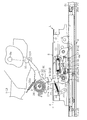
- FIG. 2 is the side view which shows the whole fall and standing state of the seat in the seatable area of the seat cushion in the seat device and its seat slide device
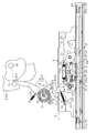
- FIG. 3 is a partially enlarged side view showing a state where the sheet is raised from the state shown in FIG. 2.
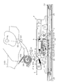
- FIG. 2 is a partially enlarged side view of the seat slide device shown in FIG.
- FIG. 5 is a partially enlarged side view showing a state in which the sheet is raised from the state shown in FIG. 4.
- (A) is a partial cross-sectional view which shows the locked state of the lock lever shown in FIG. 2,
- (b) is a partial cross-sectional view which similarly shows a lock release state.
- a seat slide device 1 shown in FIGS. 1A and 1B is employed in a second seat device 2 or a third seat device 2 provided in a station wagon or the like, and a lower rail 4 fixed to a floor 3 and a front and rear with respect to the lower rail 4. And an upper rail 5 movably attached in the direction X.
- the seat 6 attached to the upper rail 5 has a seat cushion 7 and a seat back 8.
- the seat cushion 7 incorporates a seat cushion frame 9 shown in FIGS.
- the seat cushion 7 rotates together with the seat cushion frame 9 and can take a seat lying state D and a seat standing state U.
- the seat back 8 is maintained in an upright state.
- the seat cushion 7 is switched to the seat standing state, the seat cushion 7 is disposed so as to overlap the seat back 8.
- the movement region of the upper rail 5 relative to the lower rail 4 is divided into a rear seatable region A and a front non-seatable region B along the front-rear direction X.
- the seatable area A includes a plurality of lines arranged in a line along the moving direction of the upper rail 5 (the front-rear direction X).
- a lock hole 11 (lock portion) is formed, and a plurality of lock holes 11 constituting two groups are formed in the non-sitting region B.
- a lock lever 12 (lock member) is supported on the upper rail 5 so as to be rotatable about a support shaft 13 in the vertical direction.
- the lock lever 12 includes a lock arm 14 that can be engaged with and disengaged from each lock hole 11 of the lower rail 4, and a handle arm 15 that extends from the lock arm 14 and interlocks with the handle 16.
- the lock spring 17 (torsion coil spring)
- the upper end portion 17 a is hooked on the upper rail 5
- the lower end portion 17 b is hooked on the lock lever 12.
- the lock lever 12 has a lock position P12 that restricts the movement of the upper rail 5 with respect to the lower rail 4 by the claw 14a of the lock arm 14 being engaged with the lock hole 11 by the force of the lock spring 17.
- the lock release position Q12 that allows the upper rail 5 to move with respect to the lower rail 4 when the claw 14a of the lock arm 14 is separated from the lock hole 11 against the force of the lock spring 17 is formed. I can take it.
- a restriction lever 18 (a restriction member) is supported on the upper rail 5 so as to be rotatable in the front-rear direction X about the support shaft 19.
- the restriction lever 18 includes a restriction arm 20 that extends downward from the support shaft 19 and an interlocking arm 21 that extends upward from the support shaft 19.
- the mounting plate 22 attached to the upper rail 5 and the interlocking arm 21 are connected by a regulating spring 23 (tensile coil spring).
- a guide cam 24 is formed on the lower rail 4 so as to be located on the opposite side of the lock hole 11.
- the guide cam 24 is formed along the front-rear direction X over the entire seatable area A and non-seatable area B shown in FIGS.
- the guide cam 24 is divided into a restriction release portion 25 formed in the seatable area A and a restriction capable portion 26 formed in the non-sitting area B. Engagement surfaces 25a and 26a continuously formed in the front-rear direction X across the restriction releasing portion 25 and the restrictable portion 26 are engaged at different distances from the rotation center of the support shaft 19 of the restriction lever 18.
- the distance from the rotation center of the support shaft 19 on the surface 25a is set to be larger than the distance from the rotation center of the support shaft 19 on the engagement surface 26a.
- the engaging surfaces 25a and 26a are smoothly continuous so that no step is generated at the boundary between the seatable area A and the non-sitting area B.
- a guide roller 27 (guide portion) that is engaged with the engagement surfaces 25 a and 26 a of the restriction release portion 25 and the restrictable portion 26 is attached to the lower end portion of the restriction arm 20 of the restriction lever 18.
- the abutment arm 28 (abutment portion) is located on the restriction arm 20 of the restriction lever 18 between the support shaft 19 and the guide roller 27. 14 is projected toward 14 and inserted into the lock arm 14.
- the lock arm 14 of the lock lever 12 is formed with a contact portion 29 on which the contact arm 28 of the restriction lever 18 can contact.
- an interlocking lever 30 (interlocking member) is supported above the regulating lever 18 so as to be rotatable about a support shaft 31.
- the interlocking lever 30 is in a direction R in which the interlocking arm 32 and the seat lever 33 that can rotate relative to each other about the support shaft 31 and the crossing angle between the interlocking arm 32 and the seat lever 33 are increased.
- a pressure accumulating spring 34 that biases the interlocking arm 32 is provided.
- the interlocking arm 32 stops in a state where the interlocking arm 32 is opened to the maximum from the seat lever 33 (see FIGS.
- the lever 33 is simultaneously rotated with the lever 33 opened to the maximum.
- the interlocking arm 21 of the regulating lever 18 and the interlocking arm 32 of the interlocking lever 30 can come into contact with each other at the interlocking portions 21a and 32a.
- the distal end 33t of the seat lever 33 of the interlocking lever 30 is slidably pressed by a press contact spring 33a to a press contact portion 35 that can rotate about a rotation fulcrum 9a of the seat cushion frame 9.
- the interlocking arm 32 of the interlocking lever 30 is held while the restriction lever 18 is held at the restriction release position Q18.
- the pressure accumulating spring 34 is rotated in the direction R in which the crossing angle with the seat lever 33 is enlarged by the restoring force of the pressure accumulating spring 34, and is rotated together with the seat lever 33 by the force of the pressure contact spring 33 a and is separated from the interlock arm 21 of the regulating lever 18. Therefore, in the seatable area A, the seat cushion frame 9 and the upper rail 5 in the seat standing state U can be held at an arbitrary position within the range where the lock hole 11 is formed.
- the contact arm 28 of the regulating lever 18 pushes up the contact portion 29 of the lock arm 14 and the lock lever 12 is held at the unlock position Q12.
- This state is referred to as a holding state F of the lock lever 12. Therefore, in the non-sitting area B, the seat cushion frame 9 in the seat lying state D cannot be held at an arbitrary position in the area B.
- the lock lever 12 is shown in FIG. 6 (a) only for the lock holes 11 of each group arranged at a limited position in the non-sitting area B of the lower rail 4. It is possible to switch between the lock position P12 and the lock release position Q12 shown in FIG. Therefore, the seat cushion frame 9 in the seat standing state U can be held only at a predetermined position in the non-sitting area B.
- This embodiment has the following effects.
- the lock lever 12 can be easily held at the unlocking position Q12 at the restrictable position P18 of the restriction lever 18 simply by bringing the contact portion 29 of the lock lever 12 and the contact arm 28 of the restriction lever 18 into contact with each other. Therefore, the interlocking structure between the lock lever 12 and the regulating lever 18 can be simplified.
- the lock lever 12 can be easily urged by the lock spring 17 to be easily placed at the lock position P12, and the restriction lever 18 can be urged by the restriction spring 23 to be easily placed at the restrictable position P18.
- the restriction lever 18 since the force of the lock spring 17 overcomes the force of the restriction spring 23 due to the contact between the contact portion 29 of the lock lever 12 and the contact arm 28 of the restriction lever 18, the restriction lever 18 is replaced with the force of the restriction spring 23. Accordingly, the lock lever 12 can be easily disposed at the lock position P12 by being disposed at the restriction release position Q18.
- the lock lever 12 can be selectively switched to the lock position P12 and the lock release position Q12. However, in the seat lying state D in the non-sitting area B, the lock lever 12 can be disposed at the unlock position Q12 but cannot be disposed at the lock position P12.
- the seat cushion frame 9 and the restricting lever 18 can be interlocked with each other by the interlocking lever 30 so that the restricting lever 18 can be disposed at the restricting release position Q18 in the seat lying state D in the seatable area A of the upper rail 5.
- the restriction lever 18 can be disposed at the restriction possible position P18.
- the restriction lever 18 can be disposed at the restriction release position Q18.
- the seat slide device can be easily set to the pressure accumulating state E, the holding state F, and the holding releasing state G.
- the restriction lever 18 includes the engagement surface 25 a of the restriction release portion 25 and the engagement surface 26 a of the restriction enable portion 26, the guide roller 27, and the restriction spring 23 in the guide cam 24 of the lower rail 4. Can be selectively set to the restrictable position P18 and the restriction release position Q18. However, if the guide cam is formed in a groove shape, the guide roller 27 is moved along the groove-shaped guide cam, and the position of the guide roller 27 in the height direction is restricted, the restriction spring 23 can be omitted. it can.
- interlocking arm of the interlocking lever 32a ... Interlocking part, 33 ... Seat lever of interlocking lever, 34 ... Accumulated spring of interlocking lever, P12 ... Lock position of lock lever, Q12 ... Lock release position of lock lever, 18: Restriction position of restriction lever, Q18: Restriction release position of restriction lever, A: Seatable area, B: Non-sitting area, D: Seat lying down, U: Seat standing up, E: Accumulated pressure, F: Holding State, G: Holding release state, X: Upper rail moving direction (front-rear direction).
Landscapes
- Engineering & Computer Science (AREA)
- Aviation & Aerospace Engineering (AREA)
- Transportation (AREA)
- Mechanical Engineering (AREA)
- Seats For Vehicles (AREA)
Abstract
規制レバー(18)の案内ローラ(27)が規制解除部(25)の係合面(25a)に係合している場合、アッパレール(5)の着座可能領域におけるシート倒伏状態(D)で、規制レバー(18)を規制解除位置(Q18)に配置して、ロックレバー(12)をロック位置及びロック解除位置(Q12)に選択的に配置できる。規制レバー(18)の案内ローラ(27)が規制可能部(26)の係合面(26a)に係合している場合、アッパレール(5)の着座不可領域におけるシート倒伏状態(D)で、規制レバー(18)を規制可能位置(P18)に配置して、ロックレバー(12)をロック解除位置(Q12)に保持できる。
Description
本発明は、車両のシートスライド装置において、ロアレールに対しアッパレールを移動可能に支持した際に、ロアレールに対するアッパレールの移動を阻止するロック状態と許容するロック解除状態とを取り得るロック機構、並びに、そのシートスライド装置を利用したシート装置に関するものである。
前後方向に複数列のシートを有するワンボックスカー等に使用されるシートスライド装置として、特許文献1に記載のチップアップ・スライド式自動車用シートが開示されている。この自動車用シートにおいては、ロアレールに対しアッパレールが移動可能に支持され、アッパレールには主ロック機構の主ロックプレートと補助ロック機構の補助ロックプレートとが支持されている。ロアレールには主ロックプレートが係脱される主ロック孔と補助ロックプレートが係脱される補助ロック孔とが配設されている。例えば、シートクッションが着座状態にあり、補助ロックプレートがスライドロック領域に位置している場合には、主ロックプレートが主ロック孔に係入されるとともに、補助ロックプレートも補助ロック孔に係入され、シートが所定の位置に保持される。また、シートクッションが着座状態にあり、補助ロックプレートが非ロック領域に位置している場合には、チップアップ機構の一部がリンク機構の一部に当接して、主ロックプレートが主ロック孔から離脱するとともに、補助ロックプレートも補助ロック孔から離脱する。
しかし、前述したように、主ロック機構に加えて、補助ロック機構も採用すると、シートスライド装置の構造が複雑になるという問題があった。
この発明は、上記の補助ロック機構をなくすとともに、その補助ロック機構に代わる新たな構成を提供することにより、シートスライド装置及びシート装置の構造を簡単にすることを目的としている。
次に、後述する実施形態の図面中の符号を参照して、本発明を説明する。
本願の第1の態様にかかるシートスライド装置(1)は、フロア(3)に固定されるロアレール(4)と、シート(6)に取り付けられ、ロアレール(4)に対して移動可能に支持されたアッパレール(5)と、アッパレール(5)の移動方向(X)に沿って前記ロアレール(4)に並設した複数のロック部(11)と、ロック部材(12)とを備えている。ロック部材(12)は、アッパレール(5)に取り付けられ、ロアレール(4)のロック部(11)に係合されて、ロアレール(4)に対するアッパレール(5)の移動を規制するロック位置(P12)と、ロアレール(4)のロック部(11)に対する係合が解除されてロアレール(4)に対するアッパレール(5)の移動を可能にするロック解除位置(Q12)とに切り替えられる。アッパレール(5)には、ロック部材(12)をロック位置(P12)及びロック解除位置(Q12)に選択的に切り替え可能な規制解除位置(Q18)と、ロック部材(12)をロック解除位置(Q12)に保持可能な規制可能位置(P18)とに切り替え可能な規制部材(18)を設けている。ロアレール(4)には、この規制部材(18)を規制解除位置(Q18)に配置する規制解除部(25)と、規制部材(18)を規制可能位置(P18)に配置する規制可能部(26)とを設けている。
第1の態様では、アッパレール(5)の規制部材(18)を規制解除位置(Q18)に配置する規制解除部(25)と、その規制部材(18)を規制可能位置(P18)に配置する規制可能部(26)とをロアレール(4)に設けるだけの簡単な構造により、規制部材(18)の規制解除位置(Q18)でロック部材(12)をロック位置(P12)及びロック解除位置(Q12)に切り替えたり、規制部材(18)の規制可能位置(P18)でロック部材(12)をロック解除位置(Q12)に保持したりすることができる。
第2の態様において、前記規制解除部(25)及び規制可能部(26)は、アッパレール(5)の移動方向(X)に沿って、前記ロアレールに連続して設けられた2つの係合面(25a,26a)であって、規制部材(18)と係合される。第2の態様では、規制部材(18)に係合される係合面(25a,26a)をロアレール(4)に設けるだけで、規制解除部(25)と規制可能部(26)とをロアレール(4)に容易に設けることができる。
第3の態様において、前記ロック部材(12)及び規制部材(18)は、規制部材(18)の規制可能位置(P18)にて互いに当接し得る当接部(28,29)をそれぞれ有している。第3の態様では、ロック部材(12)及び規制部材(18)をそれらの当接部(28,29)にて互いに当接させるだけで、規制部材(18)の規制可能位置(P18)でロック部材(12)をロック解除位置(Q12)に容易に保持することができる。
第4の態様において、前記ロック部材(12)をロック位置(P12)に向かって付勢するロックばね(17)と、前記規制部材(18)を規制可能位置(P18)に向かって付勢する規制ばね(23)とを有し、ロック部材(12)及び規制部材(18)の各当接部(28,29)において、ロックばね(17)の力が規制ばね(23)の力に打ち勝って、ロック部材(12)がロック位置(P12)に配置される。第4の態様では、ロックばね(17)によりロック部材(12)を付勢してロック位置(P12)に容易に配置するとともに、規制ばね(23)により規制部材(18)を付勢して規制可能位置(P18)に容易に配置することができる。さらには、ロック部材(12)の当接部(29)と規制部材(18)の当接部(28)との当接により、ロックばね(17)の力が規制ばね(23)の力に打ち勝つため、規制部材(18)を規制ばね(23)の力に抗して規制解除位置(Q18)に配置して、ロック部材(12)を容易にロック位置(P12)に配置することができる。
第5の態様において、前記ロアレール(4)に対するアッパレール(5)の移動領域は、規制部材(18)を規制解除位置(Q18)に配置可能な着座可能領域(A)と、規制部材(18)を規制可能位置(P18)に配置可能な着座不可領域(B)とを有している。第5の態様では、アッパレール(5)の移動領域のうち、着座可能領域(A)でロック部材(12)をロック位置(P12)及びロック解除位置(Q12)に配置することができ、着座不可領域(B)でロック部材(12)をロック解除位置(Q12)に配置することができる。
第6の態様においては、前記シートを構成するシートクッション(7)に着座し得るシート倒伏状態(D)と、そのシート倒伏状態(D)からシートクッション(7)を起立させたシート起立状態(U)とに切り替え可能なシートクッションフレーム(9)と、前記シートクッションフレーム(9)のシート倒伏状態(D)とシート起立状態(U)とにおいて、前記規制部材及びシートクッションフレームに連動する連動部材(30)とを備えている。この連動部材(30)は、シートクッション(7)の着座可能領域(A)におけるシート倒伏状態(D)で、規制部材(18)を規制解除位置(Q18)に配置し得るとともに、シートクッション(7)の着座不可領域(B)におけるシート倒伏状態(D)で、規制部材(18)を規制可能位置(P18)に配置し得る。第6の態様では、シートクッションフレーム(9)と規制部材(18)とを連動部材(30)によって互いに連動させ、アッパレール(5)の着座可能領域(A)におけるシート倒伏状態(D)で規制部材(18)を規制解除位置(Q18)に配置し得るとともに、アッパレール(5)の着座不可領域(B)におけるシート倒伏状態(D)で、規制部材(18)を規制可能位置(P18)に配置し得る。
第7の態様において、前記連動部材(30)は、前記シートクッションフレーム(9)に連動するシートレバー(33)と、このシートレバー(33)に対して相対回動し得るとともに、前記規制部材(18)に連動する連動腕(32)と、このシートレバー(33)と連動腕(32)との相対回動に伴って蓄圧される蓄圧ばね(34)とを有している。前記規制部材(18)は、前記アッパレールに回動可能に支持され、かつ、前記連動部材(30)の連動腕(32)に連動する連動部(21a)と、前記ロック部材(12)に連動する連動部(28)とを有している。シートクッション(7)の着座可能領域(A)におけるシート倒伏状態(D)で、規制解除位置(Q18)にある規制部材(18)の連動部(21a)に、連動部材(30)の連動腕(32)が連動し、蓄圧ばね(34)に蓄圧される蓄圧状態(E)と、シートクッション(7)の着座不可領域(B)におけるシート倒伏状態(D)で、規制可能位置(P18)にある規制部材(18)の連動部(21a)を、連動部材(30)の連動腕(32)が蓄圧ばね(34)の蓄圧により保持する保持状態(F)と、シートクッション(7)の着座不可領域(B)におけるシート起立状態(U)で、連動部材(30)の連動腕(32)が連動部材(30)のシートレバー(33)とともに回動し、規制部材(18)を規制解除位置(Q18)に配置し得る保持解除状態(G)とに、前記シートスライド装置が切り替えられる。第7の態様では、連動部材(30)のシートレバー(33)、連動腕(32)、及び蓄圧ばね(34)により、蓄圧状態(E)、保持状態(F)、及び保持解除状態(G)に、前記シートスライド装置を容易に切り替えることができる。
第8の態様はシート装置(2)に関する。そのシート装置(2)は、前述したシートスライド装置(1)を備え、前記シート(6)は前記シートクッション(7)と共にシートバック(8)を備えている。そのシートバック(8)は起立した状態に維持され、前記シートクッション(7)がシート起立状態(U)に切り替えられたとき、前記シートクッション(7)は前記シートバック(8)に重なるように配置される。
本発明は、シートスライド装置(1)及びシート装置(2)の構造を簡単にすることができる。
以下、本発明の一実施形態について図面を参照して説明する。
図1(a)(b)に示すシートスライド装置1は、ステーションワゴン等に設けられるセカンドシート装置2またはサードシート装置2に採用され、フロア3に固定されたロアレール4と、ロアレール4に対し前後方向Xへ移動可能に取り付けられたアッパレール5とを備えている。アッパレール5に取り付けられたシート6は、シートクッション7とシートバック8とを有している。シートクッション7には図2~5に示すシートクッションフレーム9が内蔵されている。シートクッション7は、シートクッションフレーム9とともに回動して、シート倒伏状態Dとシート起立状態Uとを取り得る。シートバック8は起立した状態に維持されている。前記シートクッション7がシート起立状態に切り替えられたとき、シートクッション7は前記シートバック8に重なるように配置される。
図1(a)(b)に示すように、ロアレール4に対するアッパレール5の移動領域は、前後方向Xに沿い、後側の着座可能領域Aと前側の着座不可領域Bとに区分されている。図1(a)(b)及び図6(a)(b)に示すように、ロアレール4において、着座可能領域Aにはアッパレール5の移動方向(前後方向X)に沿って一列に並ぶ複数のロック孔11(ロック部)が形成され、着座不可領域Bには2つのグループを構成する複数のロック孔11が形成されている。
図2~5及び図6(a)(b)に示すように、アッパレール5にはロックレバー12(ロック部材)が支軸13を中心に上下方向へ回動可能に支持されている。ロックレバー12は、ロアレール4の各ロック孔11に係脱し得るロック腕14と、ロック腕14から延設されてハンドル16と連動するハンドル腕15とを有している。ロックばね17(ねじりコイルばね)の両端部17a,17bのうち、上端部17aはアッパレール5に引掛けられ、下端部17bはロックレバー12に引掛けられている。ロックレバー12は、図6(a)に示すようにロックばね17の力により、ロック腕14の爪14aがロック孔11に係入されてロアレール4に対するアッパレール5の移動を規制するロック位置P12と、図6(b)に示すようにロックばね17の力に抗してロック腕14の爪14aがロック孔11から離脱してロアレール4に対するアッパレール5の移動を可能にするロック解除位置Q12とを取り得る。
図2~5に示すように、アッパレール5には規制レバー18(規制部材)が支軸19を中心に前後方向Xへ回動可能に支持されている。規制レバー18は、支軸19から下方へ延設された規制腕20と、支軸19から上方へ延設された連動腕21とを有している。アッパレール5に取着された取付板22と連動腕21とは規制ばね23(引張コイルばね)によって連結されている。
図6(a)(b)に示すように、ロック孔11に対して反対側に位置するように、ロアレール4には案内カム24が形成されている。その案内カム24は、図1(a)(b)に示す着座可能領域A及び着座不可領域Bの全体にわたり、前後方向Xに沿って形成されている。図2~5に示すように、案内カム24は、着座可能領域Aに形成された規制解除部25と、着座不可領域Bに形成された規制可能部26とに区分されている。規制解除部25及び規制可能部26にわたり、前後方向Xへ連続して形成された係合面25a,26aは、規制レバー18の支軸19の回動中心から離間する距離を異にし、係合面25aにおける支軸19の回動中心からの距離が係合面26aにおける支軸19の回動中心からの距離より大きく設定されている。それらの係合面25a,26aは、着座可能領域Aと着座不可領域Bとの間の境界部で段差が生じないように滑らかに連続している。規制レバー18の規制腕20の下端部には規制解除部25及び規制可能部26の係合面25a,26aに係合される案内ローラ27(案内部)が取着されている。
図2~5に示すように、規制レバー18の規制腕20には支軸19と案内ローラ27との間に位置するように、当接腕28(当接部)がロックレバー12のロック腕14に向けて突設され、そのロック腕14に挿入されている。ロックレバー12のロック腕14には規制レバー18の当接腕28が当接し得る当接部29が形成されている。
図2,3に示すように、規制解除部25の係合面25aに案内ローラ27が係合した状態では、案内ローラ27が規制ばね23の力に抗して下動するため、規制レバー18が規制解除位置Q18に配置され、規制腕20が下方へ回動して当接腕28が当接部29から下方へ離れる。そのため、この状態では、ロックレバー12のロック腕14を、図6(a)に示すロック位置P12と、図6(b)に示すロック解除位置Q12とに選択的に配置することができる。
一方、図4に示すように、規制可能部26の係合面26aに案内ローラ27が相対した状態では、蓄圧ばね43及び規制ばね23の合力がロックばね17の力に打ち勝つため、案内ローラ27が上動して規制レバー18が規制可能位置P18に配置される。
図2~5に示すように、規制レバー18の上方には連動レバー30(連動部材)が支軸31を中心に回動可能に支持されている。連動レバー30は、支軸31を中心に相対回動し得る連動腕32及びシートレバー33と、支軸31に巻装されて連動腕32とシートレバー33との交差角度を拡大する方向Rへ連動腕32を付勢する蓄圧ばね34とを有している。連動腕32は、交差角度の拡大方向Rへ、シートレバー33から最大に開いた状態(図3,5参照)で停止し、その拡大方向Rとは反対の方向へは、連動腕32及びシートレバー33が最大に開いた状態のまま、同時に回動する。規制レバー18の連動腕21と連動レバー30の連動腕32とはそれぞれの連動部21a,32aにおいて互いに当接し得る。連動レバー30のシートレバー33の先端33tは、シートクッションフレーム9の回動支点9aを中心に回動し得る圧接部35に対し、圧接ばね33aにより摺動可能に圧接されている。
次に、シート装置2及びそのシートスライド装置1の作用を説明する。
図1(a)及び図2に示すように、アッパレール5がロアレール4の着座可能領域Aにあってシートクッションフレーム9がシート倒伏状態Dにある場合には、規制レバー18の案内ローラ27が規制解除部25の係合面25aに係合される。そのため、規制レバー18が規制ばね23の力に抗して回動して規制解除位置Q18に配置され、規制レバー18の連動腕21が連動レバー30の連動腕32を押して蓄圧ばね34が蓄圧状態Eにセットされる。規制レバー18が規制解除位置Q18に配置された状態では、ロック腕14の当接部29と規制レバー18の当接腕28との間に隙間28aが生じ、ロアレール4の着座可能領域Aにある複数のロック孔11に対して、ロックレバー12の爪14aが係入し、ロックレバー12が図6(a)に示すロック位置P12に配置される。また、オペレータがロックばね17の力に抗してロックレバー12を回動させれば、ロックレバー12を図6(b)に示すロック解除位置Q12に切り替えることができる。従って、着座可能領域Aでは、シート倒伏状態Dにおけるシートクッションフレーム9及びアッパーレール5を、ロック孔11が形成された範囲内の任意の位置に保持することができる。
図2に示す蓄圧状態Eでシートクッションフレーム9を図3に示すようにシート起立状態Uに配置すると、規制レバー18が規制解除位置Q18に保持されたまま、連動レバー30の連動腕32は、蓄圧ばね34の復帰力により、シートレバー33との交差角度の拡大方向Rへ回動しながら、圧接ばね33aの力によりシートレバー33とともに回動し、規制レバー18の連動腕21から離間する。従って、着座可能領域Aでは、シート起立状態Uにおけるシートクッションフレーム9及びアッパーレール5を、ロック孔11が形成された範囲内の任意の位置に保持することができる。
図1(b)及び図4に示すように、アッパレール5がロアレール4の着座不可領域Bにあって、シートクッションフレーム9がシート倒伏状態Dにある場合には、規制レバー18の案内ローラ27が規制可能部26の係合面26aに係合される。そのため、連動レバー30の連動腕32は、蓄圧ばね34の復帰力により、シートレバー33に対して交差角度の拡大方向Rへ開き、規制レバー18の連動腕21を蓄圧ばね34の蓄圧により保持して、規制レバー18を規制可能位置P18に配置する。それに伴い、規制レバー18の当接腕28がロック腕14の当接部29を押し上げてロックレバー12がロック解除位置Q12に保持される。この状態をロックレバー12の保持状態Fと呼ぶ。従って、着座不可領域Bでは、シート倒伏状態Dのシートクッションフレーム9を、その領域B内の任意の位置において保持することはできない。
図4に示すロックレバー12の保持状態Fで、シートクッションフレーム9を図5に示すようにシート起立状態Uにセットすると、連動レバー30の連動腕32は、蓄圧ばね34の復帰力により、シートレバー33との交差角度の拡大方向Rへ開きながら、圧接ばね33aの力により、シートレバー33とともに回動し、規制レバー18の連動腕21から離間する。ロックばね17の力は規制ばね23の力に打ち勝つため、ロック腕14の当接部29が規制レバー18の当接腕28を押し下げ、規制レバー18が規制ばね23の力に抗して回動して規制解除位置Q18に配置される。規制レバー18の規制解除位置Q18では、ロアレール4の着座不可領域B内の限られた位置に配設された各グループのロック孔11に対してのみ、ロックレバー12を図6(a)に示すロック位置P12と図6(b)に示すロック解除位置Q12とに切り替えることができる。従って、着座不可領域Bの所定位置でのみシート起立状態Uのシートクッションフレーム9を保持することができる。
本実施形態は下記の効果を有する。
(1) 規制レバー18の案内ローラ27が規制解除部25の係合面25aに係合している場合には、規制レバー18を規制解除位置Q18に配置して、ロックレバー12をロック位置P12とロック解除位置Q12とに切り替えることができる。また、規制レバー18の案内ローラ27が規制可能部26の係合面26aに係合している場合には、規制レバー18を規制可能位置P18に配置して、ロックレバー12をロック解除位置Q12に保持することができる。その規制解除部25の係合面25a及び規制可能部26の係合面26aを有する案内カム24をアッパレール5の移動方向(前後方向X)に沿ってロアレール4に設けるだけでよいため、シートスライド装置1の構造を簡単にすることができる。
(2) ロックレバー12の当接部29と規制レバー18の当接腕28とを互いに当接させるだけで、規制レバー18の規制可能位置P18でロックレバー12をロック解除位置Q12に容易に保持することができるため、ロックレバー12と規制レバー18との連動構造を簡単にすることができる。
(3) ロックばね17によりロックレバー12を付勢して容易にロック位置P12に配置するとともに、規制ばね23により規制レバー18を付勢して容易に規制可能位置P18に配置することができる。しかし、ロックレバー12の当接部29と規制レバー18の当接腕28との当接により、ロックばね17の力が規制ばね23の力に打ち勝つため、規制レバー18を規制ばね23の力に抗して規制解除位置Q18に配置して、ロックレバー12を容易にロック位置P12に配置することができる。
(4) アッパレール5の移動領域のうち、着座可能領域Aにおけるシート倒伏状態Dでは、ロックレバー12をロック位置P12及びロック解除位置Q12に選択的に切り替えることができる。しかし、着座不可領域Bにおけるシート倒伏状態Dでは、ロックレバー12をロック解除位置Q12に配置することはできても、ロック位置P12に配置することができない。
(5) シートクッションフレーム9と規制レバー18とを、連動レバー30によって互いに連動させ、アッパレール5の着座可能領域Aにおけるシート倒伏状態Dで、規制レバー18を規制解除位置Q18に配置することができ、アッパレール5の着座不可領域Bにおけるシート倒伏状態Dで、規制レバー18を規制可能位置P18に配置することができる。また、その着座可能領域A及び着座不可領域Bにおけるシート起立状態Uでは、規制レバー18を規制解除位置Q18に配置することができる。
(6) 連動レバー30におけるシートレバー33、連動腕32、及び、蓄圧ばね34により、シートスライド装置を、蓄圧状態E、保持状態F、及び、保持解除状態Gに容易に設定することができる。
なお、前述した実施形態では、ロアレール4の案内カム24における規制解除部25の係合面25a及び規制可能部26の係合面26aと、案内ローラ27と、規制ばね23とにより、規制レバー18を、規制可能位置P18と規制解除位置Q18とに選択的に設定することができる。しかし、案内カムを溝状に形成して、案内ローラ27をその溝状の案内カムに沿って移動させ、案内ローラ27の高さ方向の位置を規制すれば、規制ばね23を省略することができる。
1…シートスライド装置、2…シート装置、3…フロア、4…ロアレール、5…アッパレール、7…シートクッション、9…シートクッションフレーム、11…ロアレールのロック孔(ロック部)、12…ロックレバー(ロック部材)、17…ロックばね、18…規制レバー(規制部材)、21a…規制レバーの連動部、23…規制ばね、25…ロアレールの規制解除部、25a…係合面、26…ロアレールの規制可能部、26a…係合面、28…規制レバーの当接部(連動部)、29…ロックレバーの当接部、30…連動レバー(連動部材)、32…連動レバーの連動腕、32a…連動部、33…連動レバーのシートレバー、34…連動レバーの蓄圧ばね、P12…ロックレバーのロック位置、Q12…ロックレバーのロック解除位置、P18…規制レバーの規制可能位置、Q18…規制レバーの規制解除位置、A…着座可能領域、B…着座不可領域、D…シート倒伏状態、U…シート起立状態、E…蓄圧状態、F…保持状態、G…保持解除状態、X…アッパレールの移動方向(前後方向)。
Claims (8)
- フロアに固定されるロアレールと、
シートに取り付けられ、前記ロアレールに対して移動可能に支持されたアッパレールと、
前記アッパレールの移動方向に沿って前記ロアレールに並設した複数のロック部と、
前記アッパレールに取り付けられ、前記ロアレールのロック部に係合されて、ロアレールに対するアッパレールの移動を規制するロック位置と、ロアレールのロック部に対する係合が解除されて、ロアレールに対するアッパレールの移動を可能にするロック解除位置とに切り替えられるロック部材とを備え、
前記アッパレールには、前記ロック部材をロック位置及びロック解除位置に選択的に切り替え可能な規制解除位置と、前記ロック部材をロック解除位置に保持可能な規制可能位置とに切り替え可能な規制部材を設け、
前記ロアレールには、この規制部材を規制解除位置に配置する規制解除部と、規制部材を規制可能位置に配置する規制可能部とを設けた
ことを特徴とするシートスライド装置。 - 前記規制解除部及び規制可能部は、前記アッパレールの移動方向に沿って、前記ロアレールに連続して設けられた2つの係合面であって、前記規制部材と係合されることを特徴とする請求項1に記載のシートスライド装置。
- 前記ロック部材及び規制部材は、前記規制部材の規制可能位置にて互いに当接し得る当接部をそれぞれ有していることを特徴とする請求項1または請求項2に記載のシートスライド装置。
- 前記ロック部材をロック位置に向かって付勢するロックばねと、前記規制部材を規制可能位置に向かって付勢する規制ばねとを有し、前記ロック部材及び規制部材の各当接部において、前記ロックばねの力が規制ばねの力に打ち勝って、ロック部材がロック位置に配置されることを特徴とする請求項3に記載のシートスライド装置。
- 前記ロアレールに対するアッパレールの移動領域は、前記規制部材を規制解除位置に配置可能な着座可能領域と、前記規制部材を規制可能位置に配置可能な着座不可領域とを有していることを特徴とする請求項1~4のいずれか一項に記載のシートスライド装置。
- 前記シートを構成するシートクッションに着座し得るシート倒伏状態と、そのシート倒伏状態からシートクッションを起立させたシート起立状態とに切り替え可能なシートクッションフレームと、
前記シートクッションフレームのシート倒伏状態とシート起立状態とにおいて、前記規制部材及びシートクッションフレームに連動する連動部材とを備え、
この連動部材は、シートクッションの着座可能領域におけるシート倒伏状態で、前記規制部材を規制解除位置に配置し得るとともに、シートクッションの着座不可領域におけるシート倒伏状態で、前記規制部材を規制可能位置に配置し得る
ことを特徴とする請求項5に記載のシートスライド装置。 - 前記連動部材は、前記シートクッションフレームに連動するシートレバーと、
このシートレバーに対して相対回動し得るとともに、前記規制部材に連動する連動腕と、このシートレバーと連動腕との相対回動に伴って蓄圧される蓄圧ばねとを有し、
前記規制部材は、前記アッパレールに回動可能に支持され、かつ、前記連動部材の連動腕に連動する連動部と、前記ロック部材に連動する連動部とを有し、
前記シートクッションの着座可能領域におけるシート倒伏状態で、規制解除位置にある規制部材の連動部に、前記連動部材の連動腕が連動し、蓄圧ばねに蓄圧される蓄圧状態と、
前記シートクッションの着座不可領域におけるシート倒伏状態で、規制可能位置にある規制部材の連動部を、前記連動部材の連動腕が蓄圧ばねの蓄圧により保持する保持状態と、
前記シートクッションの着座不可領域におけるシート起立状態で、前記連動部材の連動腕が連動部材のシートレバーとともに回動し、前記規制部材を規制解除位置に配置し得る保持解除状態とに、前記シートスライド装置が切り替えられる
ことを特徴とする請求項6に記載のシートスライド装置。 - 請求項6または請求項7に記載のシートスライド装置を備え、
前記シートは前記シートクッションと共にシートバックを備え、そのシートバックは起立した状態に維持され、前記シートクッションがシート起立状態に切り替えられたとき、前記シートクッションは前記シートバックに重なるように配置されることを特徴とするシート装置。
Priority Applications (2)
| Application Number | Priority Date | Filing Date | Title |
|---|---|---|---|
| JP2014552770A JP6113753B2 (ja) | 2012-12-17 | 2012-12-17 | シートスライド装置及びシート装置 |
| PCT/JP2012/082671 WO2014097372A1 (ja) | 2012-12-17 | 2012-12-17 | シートスライド装置及びシート装置 |
Applications Claiming Priority (1)
| Application Number | Priority Date | Filing Date | Title |
|---|---|---|---|
| PCT/JP2012/082671 WO2014097372A1 (ja) | 2012-12-17 | 2012-12-17 | シートスライド装置及びシート装置 |
Publications (1)
| Publication Number | Publication Date |
|---|---|
| WO2014097372A1 true WO2014097372A1 (ja) | 2014-06-26 |
Family
ID=50977760
Family Applications (1)
| Application Number | Title | Priority Date | Filing Date |
|---|---|---|---|
| PCT/JP2012/082671 Ceased WO2014097372A1 (ja) | 2012-12-17 | 2012-12-17 | シートスライド装置及びシート装置 |
Country Status (2)
| Country | Link |
|---|---|
| JP (1) | JP6113753B2 (ja) |
| WO (1) | WO2014097372A1 (ja) |
Cited By (1)
| Publication number | Priority date | Publication date | Assignee | Title |
|---|---|---|---|---|
| JP2021066437A (ja) * | 2021-02-04 | 2021-04-30 | テイ・エス テック株式会社 | 車両用シート |
Citations (2)
| Publication number | Priority date | Publication date | Assignee | Title |
|---|---|---|---|---|
| JP2003252089A (ja) * | 2002-02-27 | 2003-09-09 | Gifu Auto Body Industry Co Ltd | 車両の座席シートスライド装置 |
| JP2011218841A (ja) * | 2010-04-05 | 2011-11-04 | Toyota Boshoku Corp | 車両用シート |
-
2012
- 2012-12-17 WO PCT/JP2012/082671 patent/WO2014097372A1/ja not_active Ceased
- 2012-12-17 JP JP2014552770A patent/JP6113753B2/ja active Active
Patent Citations (2)
| Publication number | Priority date | Publication date | Assignee | Title |
|---|---|---|---|---|
| JP2003252089A (ja) * | 2002-02-27 | 2003-09-09 | Gifu Auto Body Industry Co Ltd | 車両の座席シートスライド装置 |
| JP2011218841A (ja) * | 2010-04-05 | 2011-11-04 | Toyota Boshoku Corp | 車両用シート |
Cited By (2)
| Publication number | Priority date | Publication date | Assignee | Title |
|---|---|---|---|---|
| JP2021066437A (ja) * | 2021-02-04 | 2021-04-30 | テイ・エス テック株式会社 | 車両用シート |
| JP7265188B2 (ja) | 2021-02-04 | 2023-04-26 | テイ・エス テック株式会社 | 車両用シート |
Also Published As
| Publication number | Publication date |
|---|---|
| JP6113753B2 (ja) | 2017-04-12 |
| JPWO2014097372A1 (ja) | 2017-01-12 |
Similar Documents
| Publication | Publication Date | Title |
|---|---|---|
| US8573674B2 (en) | Vehicle seat | |
| JP6609179B2 (ja) | 自動車用シート | |
| EP2875990B1 (en) | Vehicle seat | |
| JP4194618B2 (ja) | シートトラックスライド装置 | |
| JP5991207B2 (ja) | スライドレール | |
| JP6246927B2 (ja) | シートスライド装置 | |
| JP5933023B2 (ja) | スライドレール機構及び車両用シート | |
| JP5948946B2 (ja) | 車両用シートスライド装置 | |
| US11072263B2 (en) | Vehicle seating system | |
| JP6113753B2 (ja) | シートスライド装置及びシート装置 | |
| JP6717653B2 (ja) | 車両用シート | |
| JP5112729B2 (ja) | チップアップ・スライド式自動車用シート | |
| JP4487939B2 (ja) | 車両用シート | |
| JP5587709B2 (ja) | 車両用スライドシートのループハンドル取付構造 | |
| JP6939618B2 (ja) | 乗物用スライドレール装置 | |
| JP4555734B2 (ja) | 車両用シート構造 | |
| JP2018184026A (ja) | 乗物用スライドレール装置 | |
| WO2016171135A1 (ja) | 車両用シート | |
| WO2019112005A1 (ja) | シートスライド装置 | |
| JP2019130954A (ja) | 車両シート装置 | |
| WO2017208573A1 (ja) | 車両用シートスライド装置 | |
| JP6870535B2 (ja) | 乗物用スライドレール装置 | |
| JP4043857B2 (ja) | スライドシートの跳ね上げロック装置 | |
| JP6342490B2 (ja) | 自動車用リアシート | |
| JP6467199B2 (ja) | シートレール装置 |
Legal Events
| Date | Code | Title | Description |
|---|---|---|---|
| 121 | Ep: the epo has been informed by wipo that ep was designated in this application |
Ref document number: 12890481 Country of ref document: EP Kind code of ref document: A1 |
|
| ENP | Entry into the national phase |
Ref document number: 2014552770 Country of ref document: JP Kind code of ref document: A |
|
| NENP | Non-entry into the national phase |
Ref country code: DE |
|
| 122 | Ep: pct application non-entry in european phase |
Ref document number: 12890481 Country of ref document: EP Kind code of ref document: A1 |