WO2014092065A1 - スクロール型流体機械 - Google Patents
スクロール型流体機械 Download PDFInfo
- Publication number
- WO2014092065A1 WO2014092065A1 PCT/JP2013/083041 JP2013083041W WO2014092065A1 WO 2014092065 A1 WO2014092065 A1 WO 2014092065A1 JP 2013083041 W JP2013083041 W JP 2013083041W WO 2014092065 A1 WO2014092065 A1 WO 2014092065A1
- Authority
- WO
- WIPO (PCT)
- Prior art keywords
- scroll
- wrap
- expansion
- movable scroll
- compression
- Prior art date
- Legal status (The legal status is an assumption and is not a legal conclusion. Google has not performed a legal analysis and makes no representation as to the accuracy of the status listed.)
- Ceased
Links
Images

Classifications
-
- F—MECHANICAL ENGINEERING; LIGHTING; HEATING; WEAPONS; BLASTING
- F04—POSITIVE - DISPLACEMENT MACHINES FOR LIQUIDS; PUMPS FOR LIQUIDS OR ELASTIC FLUIDS
- F04C—ROTARY-PISTON, OR OSCILLATING-PISTON, POSITIVE-DISPLACEMENT MACHINES FOR LIQUIDS; ROTARY-PISTON, OR OSCILLATING-PISTON, POSITIVE-DISPLACEMENT PUMPS
- F04C18/00—Rotary-piston pumps specially adapted for elastic fluids
- F04C18/02—Rotary-piston pumps specially adapted for elastic fluids of arcuate-engagement type, i.e. with circular translatory movement of co-operating members, each member having the same number of teeth or tooth-equivalents
- F04C18/0207—Rotary-piston pumps specially adapted for elastic fluids of arcuate-engagement type, i.e. with circular translatory movement of co-operating members, each member having the same number of teeth or tooth-equivalents both members having co-operating elements in spiral form
- F04C18/0215—Rotary-piston pumps specially adapted for elastic fluids of arcuate-engagement type, i.e. with circular translatory movement of co-operating members, each member having the same number of teeth or tooth-equivalents both members having co-operating elements in spiral form where only one member is moving
-
- F—MECHANICAL ENGINEERING; LIGHTING; HEATING; WEAPONS; BLASTING
- F01—MACHINES OR ENGINES IN GENERAL; ENGINE PLANTS IN GENERAL; STEAM ENGINES
- F01C—ROTARY-PISTON OR OSCILLATING-PISTON MACHINES OR ENGINES
- F01C1/00—Rotary-piston machines or engines
- F01C1/02—Rotary-piston machines or engines of arcuate-engagement type, i.e. with circular translatory movement of co-operating members, each member having the same number of teeth or tooth-equivalents
-
- F—MECHANICAL ENGINEERING; LIGHTING; HEATING; WEAPONS; BLASTING
- F01—MACHINES OR ENGINES IN GENERAL; ENGINE PLANTS IN GENERAL; STEAM ENGINES
- F01C—ROTARY-PISTON OR OSCILLATING-PISTON MACHINES OR ENGINES
- F01C1/00—Rotary-piston machines or engines
- F01C1/02—Rotary-piston machines or engines of arcuate-engagement type, i.e. with circular translatory movement of co-operating members, each member having the same number of teeth or tooth-equivalents
- F01C1/0207—Rotary-piston machines or engines of arcuate-engagement type, i.e. with circular translatory movement of co-operating members, each member having the same number of teeth or tooth-equivalents both members having co-operating elements in spiral form
- F01C1/0215—Rotary-piston machines or engines of arcuate-engagement type, i.e. with circular translatory movement of co-operating members, each member having the same number of teeth or tooth-equivalents both members having co-operating elements in spiral form where only one member is moving
-
- F—MECHANICAL ENGINEERING; LIGHTING; HEATING; WEAPONS; BLASTING
- F01—MACHINES OR ENGINES IN GENERAL; ENGINE PLANTS IN GENERAL; STEAM ENGINES
- F01C—ROTARY-PISTON OR OSCILLATING-PISTON MACHINES OR ENGINES
- F01C11/00—Combinations of two or more machines or engines, each being of rotary-piston or oscillating-piston type
-
- F—MECHANICAL ENGINEERING; LIGHTING; HEATING; WEAPONS; BLASTING
- F01—MACHINES OR ENGINES IN GENERAL; ENGINE PLANTS IN GENERAL; STEAM ENGINES
- F01C—ROTARY-PISTON OR OSCILLATING-PISTON MACHINES OR ENGINES
- F01C11/00—Combinations of two or more machines or engines, each being of rotary-piston or oscillating-piston type
- F01C11/002—Combinations of two or more machines or engines, each being of rotary-piston or oscillating-piston type of similar working principle
-
- F—MECHANICAL ENGINEERING; LIGHTING; HEATING; WEAPONS; BLASTING
- F01—MACHINES OR ENGINES IN GENERAL; ENGINE PLANTS IN GENERAL; STEAM ENGINES
- F01C—ROTARY-PISTON OR OSCILLATING-PISTON MACHINES OR ENGINES
- F01C13/00—Adaptations of machines or engines for special use; Combinations of engines with devices driven thereby
- F01C13/04—Adaptations of machines or engines for special use; Combinations of engines with devices driven thereby for driving pumps or compressors
-
- F—MECHANICAL ENGINEERING; LIGHTING; HEATING; WEAPONS; BLASTING
- F01—MACHINES OR ENGINES IN GENERAL; ENGINE PLANTS IN GENERAL; STEAM ENGINES
- F01C—ROTARY-PISTON OR OSCILLATING-PISTON MACHINES OR ENGINES
- F01C21/00—Component parts, details or accessories not provided for in groups F01C1/00 - F01C20/00
- F01C21/08—Rotary pistons
-
- F—MECHANICAL ENGINEERING; LIGHTING; HEATING; WEAPONS; BLASTING
- F04—POSITIVE - DISPLACEMENT MACHINES FOR LIQUIDS; PUMPS FOR LIQUIDS OR ELASTIC FLUIDS
- F04C—ROTARY-PISTON, OR OSCILLATING-PISTON, POSITIVE-DISPLACEMENT MACHINES FOR LIQUIDS; ROTARY-PISTON, OR OSCILLATING-PISTON, POSITIVE-DISPLACEMENT PUMPS
- F04C18/00—Rotary-piston pumps specially adapted for elastic fluids
- F04C18/02—Rotary-piston pumps specially adapted for elastic fluids of arcuate-engagement type, i.e. with circular translatory movement of co-operating members, each member having the same number of teeth or tooth-equivalents
- F04C18/0207—Rotary-piston pumps specially adapted for elastic fluids of arcuate-engagement type, i.e. with circular translatory movement of co-operating members, each member having the same number of teeth or tooth-equivalents both members having co-operating elements in spiral form
- F04C18/0246—Details concerning the involute wraps or their base, e.g. geometry
- F04C18/0269—Details concerning the involute wraps
-
- F—MECHANICAL ENGINEERING; LIGHTING; HEATING; WEAPONS; BLASTING
- F04—POSITIVE - DISPLACEMENT MACHINES FOR LIQUIDS; PUMPS FOR LIQUIDS OR ELASTIC FLUIDS
- F04C—ROTARY-PISTON, OR OSCILLATING-PISTON, POSITIVE-DISPLACEMENT MACHINES FOR LIQUIDS; ROTARY-PISTON, OR OSCILLATING-PISTON, POSITIVE-DISPLACEMENT PUMPS
- F04C23/00—Combinations of two or more pumps, each being of rotary-piston or oscillating-piston type, specially adapted for elastic fluids; Pumping installations specially adapted for elastic fluids; Multi-stage pumps specially adapted for elastic fluids
- F04C23/001—Combinations of two or more pumps, each being of rotary-piston or oscillating-piston type, specially adapted for elastic fluids; Pumping installations specially adapted for elastic fluids; Multi-stage pumps specially adapted for elastic fluids of similar working principle
-
- F—MECHANICAL ENGINEERING; LIGHTING; HEATING; WEAPONS; BLASTING
- F04—POSITIVE - DISPLACEMENT MACHINES FOR LIQUIDS; PUMPS FOR LIQUIDS OR ELASTIC FLUIDS
- F04C—ROTARY-PISTON, OR OSCILLATING-PISTON, POSITIVE-DISPLACEMENT MACHINES FOR LIQUIDS; ROTARY-PISTON, OR OSCILLATING-PISTON, POSITIVE-DISPLACEMENT PUMPS
- F04C23/00—Combinations of two or more pumps, each being of rotary-piston or oscillating-piston type, specially adapted for elastic fluids; Pumping installations specially adapted for elastic fluids; Multi-stage pumps specially adapted for elastic fluids
- F04C23/02—Pumps characterised by combination with, or adaptation to, specific driving engines or motors
-
- F—MECHANICAL ENGINEERING; LIGHTING; HEATING; WEAPONS; BLASTING
- F04—POSITIVE - DISPLACEMENT MACHINES FOR LIQUIDS; PUMPS FOR LIQUIDS OR ELASTIC FLUIDS
- F04C—ROTARY-PISTON, OR OSCILLATING-PISTON, POSITIVE-DISPLACEMENT MACHINES FOR LIQUIDS; ROTARY-PISTON, OR OSCILLATING-PISTON, POSITIVE-DISPLACEMENT PUMPS
- F04C18/00—Rotary-piston pumps specially adapted for elastic fluids
- F04C18/02—Rotary-piston pumps specially adapted for elastic fluids of arcuate-engagement type, i.e. with circular translatory movement of co-operating members, each member having the same number of teeth or tooth-equivalents
-
- F—MECHANICAL ENGINEERING; LIGHTING; HEATING; WEAPONS; BLASTING
- F04—POSITIVE - DISPLACEMENT MACHINES FOR LIQUIDS; PUMPS FOR LIQUIDS OR ELASTIC FLUIDS
- F04C—ROTARY-PISTON, OR OSCILLATING-PISTON, POSITIVE-DISPLACEMENT MACHINES FOR LIQUIDS; ROTARY-PISTON, OR OSCILLATING-PISTON, POSITIVE-DISPLACEMENT PUMPS
- F04C2270/00—Control; Monitoring or safety arrangements
- F04C2270/17—Tolerance; Play; Gap
Definitions
- the present invention relates to a scroll type fluid machine, and more particularly to a scroll type fluid machine suitable for use as a compressor-integrated expander.
- a scroll type fluid machine described in Patent Document 1 includes a movable scroll in which a spiral wrap is formed, a fixed scroll in which a spiral wrap is formed that meshes with the wrap of the movable scroll, and a fixed scroll. And a support portion that supports a revolving and swinging motion, and the compression chamber and the expansion portion are formed by partitioning the working chamber between the spiral wrap of the fixed scroll and the spiral wrap of the movable scroll by a partition wall. It is configured.
- This scroll type fluid machine is, for example, a low pressure working fluid connected to a refrigeration circuit, revolving and driving the movable scroll by the expansion energy of the high pressure working fluid taken from the refrigeration circuit to the expansion portion, and taken from the refrigeration circuit to the compression portion. Is compressed by the revolving turning driving force, and the compressed working fluid is discharged to a main compressor separately provided on the refrigeration circuit side. In this way, the working fluid is expanded to recover the power, and the recovered fluid is used to compress the working fluid.
- the expansion ratio in the expansion portion is high.
- the seal clearance (hereinafter referred to as “minimum clearance”) between the movable scroll wrap and the fixed scroll wrap in the expansion portion has a greater effect on the power recovery efficiency, which may adversely affect the power recovery efficiency. is there.
- This invention is made in view of such a subject, and it aims at providing the scroll type fluid machine which reduced the influence on the power recovery efficiency of the minimum clearance in an expansion part.
- the fixed scroll and the movable scroll in which the spiral wraps are respectively formed are arranged so that the wraps face each other, and the spiral wrap of the fixed scroll and the spiral wrap of the movable scroll are arranged.
- a scroll type fluid machine that drives the compression unit with power recovered by the expansion unit, wherein a minimum clearance between the fixed scroll wrap and the movable scroll wrap in the expansion unit is set in the compression unit.
- Minimum between the fixed scroll wrap and the movable scroll wrap A configuration that is set smaller than the clearance.
- the minimum clearance between the fixed scroll wrap and the movable scroll wrap in the expansion portion is smaller than the minimum clearance between the fixed scroll wrap and the movable scroll wrap in the compression portion. Since it is set to be small, in the scroll type fluid machine that compresses the working fluid using the expansion energy of the working fluid, it is possible to reduce the influence of the minimum clearance on the power recovery efficiency in the expansion portion having a large expansion ratio.
- FIG. 5A is a partially enlarged view of a portion A shown in FIG. 5, and FIG. FIG.
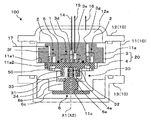
- FIG. 1 is a longitudinal sectional view of a compressor-integrated expander 100 that is a first embodiment of a scroll type fluid machine to which the present invention is applied.
- a compressor-integrated expander 100 is connected to a refrigeration circuit (evaporator and condenser) (not shown), and revolves and drives the movable scroll with respect to the fixed scroll by the expansion energy of the taken-in high-pressure refrigerant.
- the low-pressure refrigerant taken in from the refrigeration circuit is compressed by the generated turning driving force, and the compressed refrigerant is discharged to the main compressor of the refrigeration circuit.
- the expansion section 1 and the compression section 2 as working chambers And the compression unit 2 is driven by the power recovered by the expansion unit 1.
- the inflating part 1 and the compressing part 2 will be described in detail later.
- the compressor-integrated expander 100 includes a housing 10.
- the housing 10 mainly supports a scroll unit 20 including a fixed scroll 3 and a movable scroll 4, and the movable scroll 4.
- the supporting part 30 is disposed.
- the housing 10 includes a main frame 11 that fixes and supports the fixed scroll 3, a cap-shaped top shell 12 that closes the upper portion of the main frame 11, and a cap-shaped bottom shell 13 that closes the lower portion of the main frame 11.
- the main frame 11 is sandwiched between the top shell 12 and the bottom shell 13.
- an expansion side suction pipe 14 for allowing the refrigerant from the refrigeration circuit to flow into the expansion section 1 and the refrigerant expanded in the expansion section 1 are supplied to the refrigeration circuit.
- An expansion-side discharge pipe 15 that discharges toward the outlet and a compression-side discharge pipe 16 that discharges the refrigerant compressed by the compression unit 2 toward the refrigeration circuit are disposed.
- the expansion side suction pipe 14 and the expansion side discharge pipe 15 are respectively connected to the expansion side suction chamber 3d and the expansion side discharge chamber 3e formed in the fixed scroll 3, and the compression side discharge pipe 16 is connected to the top shell 12 and the main frame. 11 is connected to a compression-side discharge chamber 12a formed between them.
- a compression side suction pipe 17 for allowing the refrigerant taken in from the refrigeration circuit to flow into the compression section 2 is arranged on the outer peripheral side of the main frame 11, and the compression side suction pipe 17 is formed in the fixed scroll 3. It is connected to the compression side suction chamber 3f.
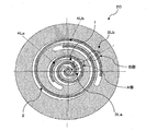
- the scroll unit 20 ensures a fixed clearance 3 and a movable scroll 4 formed with spiral wraps 3L and 4L (see FIGS. 2 and 3), respectively, so as to secure a minimum clearance described later between the wraps 3L and 4L.
- the scroll unit 20 forms an expansion portion 1 and a compression portion 2 (see FIG. 1) that constitute a working chamber for working fluid between the wrap 3L of the fixed scroll 3 and the wrap 4L of the movable scroll 4.
- the fixed scroll 3 is fixed to the uppermost seat surface 11a1 of a stepped recess 11a formed in the main frame 11 with the lap forming surface side facing downward.
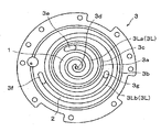
- the fixed scroll 3 is formed with an inner wrap 3La and an outer wrap 3Lb as spiral wraps 3L, and an annular intermediate partition wall 3a and an outer partition wall 3b are erected.
- the inner wrap 3La is erected more centrally than the intermediate partition wall 3a
- the outer wrap 3Lb is erected between the intermediate partition wall 3a and the outer partition wall 3b.
- the fixed scroll 3 is formed with an annular groove 3c (see FIG. 2) into which the seal ring 5 (see FIG. 1) is inserted in the end face of the intermediate partition wall 3a.
- the fixed scroll 3 has an expansion side suction chamber 3d formed in a central portion which is an inner peripheral end of the expansion portion 1, and an expansion side discharge chamber 3e is expanded inside the intermediate partition wall 3a.
- the compression side suction chamber 3f is formed at the outer peripheral end of the compression part 2 inside the outer partition wall 3b, and the compression side discharge is formed at the inner peripheral end of the compression part 2 outside the intermediate partition wall 3a.
- a hole 3g is formed therethrough.
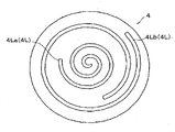
- the movable scroll 4 is placed on the intermediate pedestal surface 11a2 of the main frame 11 with the lap forming surface facing upward while being rotated by a rotation prevention mechanism 50 such as an Oldham ring. It is supported so as to be capable of revolving and turning around the axis of a fixed shaft 6 to be described later.
- the movable scroll 4 is formed with an inner wrap 4La and an outer wrap 4Lb as spiral wraps 4L.
- the wall surface of the inner wrap 4La faces the wall surface of the inner wrap 3La of the fixed scroll 3
- the wall surface of the outer wrap 4Lb faces the wall surface of the outer wrap 3Lb of the fixed scroll 3
- the wraps 4La and 4Lb have opposite spirals.
- a concave portion 4 a into which an eccentric bush 31 (described later) is inserted so as to be rotatable relative to the movable scroll 4 is formed on the surface opposite to the wrap formation surface of the movable scroll 4.
- the fixed scroll 3 and the movable scroll 4 are combined so that the wall surfaces of the respective wraps face each other, and the inflating portion 1 is provided between the inner wrap 3La of the fixed scroll 3 and the inner wrap 4La of the movable scroll 4.
- the compression portion 2 is formed between the outer wrap 3Lb of the fixed scroll 3 and the outer wrap 4Lb of the movable scroll 4.
- the scroll unit 20 is a so-called single-plate scroll in which the movable scroll 4 that forms the expansion portion 1 and the movable scroll 4 that forms the compression portion 2 are formed on the same surface of the same member. Is a unit.
- the support portion 30 is pivotally supported by the fixed shaft 6 and supports the movable scroll 4 so as to be capable of revolving around the axis X1 of the fixed shaft 6.
- the support portion 30 includes an eccentric bush 31, a needle bearing 32, a radial bearing 33, and a thrust bearing 34.
- the eccentric bush 31 is pivotally supported by the fixed shaft 6 so as to be eccentric and rotatable with respect to the axis X 1 of the fixed shaft 6, and is relatively rotated with respect to the movable scroll 4 in a recess 4 a formed in the movable scroll 4. Interpolated as possible.
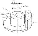
- the eccentric bush 31 includes a flange portion 31 a having a diameter larger than the inner diameter of the recess 4 a of the movable scroll 4, a columnar portion 31 b erected from the flange portion 31 a, And a balance weight 31c integrally formed on a part of the outer periphery of the portion 31a.
- the cylindrical portion 31b has a hole portion 31d having a central axis that is eccentric with respect to the axis X3 of the cylindrical portion 31b and coincides with the axis X1 of the fixed shaft 6, and is eccentric with respect to the axis X1 of the fixed shaft 6. It is formed so that it can be assembled with heart.
- a shaft portion 6a (see FIG.
- the fixed shaft 6 has a shaft portion 6 a on the upper end side, a base portion 6 b fitted into a hole portion 11 c formed so as to penetrate the bottom portion of the main frame 11, and a diameter expanded on the lower end side.
- the shaft portion 6a and the base portion 6b are formed coaxially (X1).
- the base 6b is fitted into the hole 11c and the flange 6c is bolted to the lower surface of the main frame 11 to fix the axis X1 of the fixed shaft 6 to the central axis X2 of the fixed scroll 3.
- These are fixed and fixed to the main frame 11. That is, the fixed shaft 6 only supports the eccentric bush 31 so as to be rotatable, and does not rotate itself.
- the support portion 30 including the eccentric bush 31, the needle bearing 32, the radial bearing 33, and the thrust bearing 34 fixes the cylindrical portion 31 b of the eccentric bush 31 that is pivotally supported on the fixed shaft 6 via the needle bearing 32.
- 6 is eccentric with respect to the axial center X1
- the cylindrical portion 31b is inserted into the concave portion 4a of the movable scroll 4 through the radial bearing 32 so as to be rotatable relative to the movable scroll 4, thereby moving the movable scroll. 4 is supported so as to be capable of revolving around the axis X1.
- the scroll unit 20 is configured by meshing and combining a wrap 3L of the fixed scroll 3 and a wrap 4L of the movable scroll 4.
- the expansion part 1 and the compression part 2 are set as the working chamber between the fixed scroll 3 and the movable scroll 4 during the revolution revolution of the movable scroll 4, the expansion part 1 and the compression part 2.
- This interval is called the minimum clearance.
- An oil film for lubrication is formed in the minimum clearance (in other words, the seal portion clearance), and the expansion portion 1 and the compression portion 2 as the working chamber are sealed.
- the minimum clearance is set in each of the radial direction of the scroll unit 20 and the axial direction (the height direction of each lap).
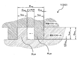
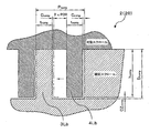
- the radial minimum clearance C is set on the expanding portion 1 side and the compressing portion 2 side, respectively, and is a partially enlarged view of the A portion and the B portion shown in FIG.
- the radial minimum clearance C exp on the expanding portion 1 side is set smaller than the radial minimum clearance C comp on the compressing portion 2 side.
- the axial minimum clearance CZ (that is, the clearance between the tip of the wrap and the groove bottom forming the wrap) is also set on the expanding portion 1 side and the compressing portion 2 side, as shown in FIG.
- the axial minimum clearance CZ exp on the expansion part 1 side is set smaller than the axial minimum clearance CZ comp on the compression part side 2. ing.
- both the radial and axial minimum clearances (C exp and CZ exp ) on the expanding portion 1 side are set smaller than the minimum clearances (C comp and CZ comp ) on the compressing portion 2 side.
- the positional relationship in the radial direction of the wrap 3L (3La, 3Lb) of the fixed scroll 3 and the wrap 4L (4La, 4Lb) of the movable scroll 4 in the expansion part 1 and the compression part 2 will be described with reference to FIGS. This will be described in detail with reference to FIG. First, the expansion part 1 side will be described. As shown in FIG. 7, the pitch of the wraps 3La and 4La of the fixed scroll 3 and the movable scroll 4 in the expanding portion 1 is P exp, and the walls of the wraps 3La and 4La of the fixed scroll 3 and the movable scroll 4 in the expanding portion 1 are used. Let the thickness be t exp . Further, as shown in FIG.
- the eccentric distance of the central axis (X1, X2 in FIG. 4) of the hole 31d with respect to the axis X3 of the cylindrical portion 31b is defined as a crank radius POR.
- the wrap 4L (4La, 4Lb) of the movable scroll 4 is cranked in the radial direction of the scroll unit 20 in the groove that forms the wrap 3L (3La, 3Lb) of the fixed scroll 3. It is possible to move by a distance twice the radius POR.
- the crank radius POR is expressed by the following formula (1).
- POR P exp / 2 ⁇ C exp ⁇ t exp (1)
- the pitch of the wraps 3Lb and 4Lb of the fixed scroll 3 and the movable scroll 4 in the compression unit 2 is P comp
- the fixed scroll 3 and the movable scroll in the expansion unit 1 are used.
- the crank radius POR is expressed by the following equation (2).
- POR P comp / 2-C comp ⁇ t comp
- the minimum radial clearances (C exp and C comp ) are specifically determined so that the pitches (P comp and P exp ) and the wall thicknesses (t comp ) are satisfied so as to satisfy Equation (5).
- t exp ) may be set.
- the pitches (P comp and P exp ) are made to coincide with each other, and the wall thickness t exp on the expansion part 1 side is formed thicker than the wall thickness t comp on the compression part 2 side, or the wall thicknesses (t comp and t exp).
- each pitch (P comp and P comp. exp ) or the wall thicknesses t comp and t exp ) do not have to coincide on the expanding portion 1 side and the compressing portion 2 side.
- the upper and lower limits of the dimensional tolerance of each pitch (P comp and P exp ) and each wall thickness (t comp and t exp ) can be expressed by the above formula (5) regardless of the size of the tolerance range. Is set to satisfy.
- the positional relationship in the axial direction of the wrap 3L (3La, 3Lb) of the fixed scroll 3 and the wrap 4L (4La, 4Lb) of the movable scroll 4 in the expansion unit 1 and the compression unit 2 will be described in detail.
- the groove depth forming the wrap 3L (inner wrap 3La) of the fixed scroll 3 in the inflating portion 1 is D exp
- the wrap 4L (inner wrap 4La) of the movable scroll 4 in the inflating portion 1 is used.
- the minimum clearances (CZ exp and CZ comp ) in the axial direction are specifically set to the groove depths (D comp and D exp ) of the fixed scroll 3 so as to satisfy the equation (8). What is necessary is just to set each lap height (h comp and h exp ) of the movable scroll 4. For example, the groove depths (D comp and D exp ) are made to coincide with each other, and the wrap height h exp of the movable scroll 4 on the expansion portion 1 side is made higher than the wrap height t comp of the movable scroll 4 on the compression portion 2 side.
- the wrap heights (h comp and h exp ) of the movable scroll 4 are made to coincide with each other, and the groove depth D exp of the fixed scroll 3 on the expansion portion 1 side is shallower than the groove depth D comp on the compression portion 2 side.
- the groove depth (D comp and D exp ) or the lap heights (h comp and h exp ) can be set to the expansion portion 1 side and the compression portion 2 if the above equation (8) is satisfied. It is not necessary to match with the side.
- the upper and lower limits of the dimensional tolerances of each groove depth (D comp and D exp ) and each lap height (h comp and h exp ) are the above formulas regardless of the dimensions of the tolerance range. Each is set so as to satisfy (8).
- the high-pressure refrigerant sucked from the expansion side suction pipe 14 is taken into the expansion section 1 through the expansion side suction chamber 3d.
- the expansion unit 1 increases the volume between the scrolls 3 and 4, and continuously orbits the movable scroll 4 around the axis X ⁇ b> 1 of the fixed scroll 3 by the expansion energy of the refrigerant.
- the refrigerant used for the revolving turning motion of the movable scroll 4 is discharged toward the refrigeration circuit via the expansion side discharge chamber 3e and the expansion side discharge pipe 15.
- the low-pressure refrigerant sucked from the compression side suction pipe 17 is taken into the compression unit 2 through the compression side suction chamber 3f.
- the compression unit 2 reduces the volume between the scrolls 3 and 4 by the revolving orbiting motion of the movable scroll 4 and compresses the refrigerant taken in along with this.
- the compressed refrigerant is discharged toward the main compressor of the refrigeration circuit through the compression side discharge hole 3g, the compression side discharge chamber 12a, and the compression side discharge pipe 16.
- the refrigerant is expanded by the expansion section 1 having a large expansion ratio, and the refrigerant is compressed by the compression section 2 having a small compression ratio using the expansion energy.
- the minimum clearance (C exp and CZ exp ) on the expansion unit 1 side is set smaller than the minimum clearance (C comp and CZ comp ) on the compression unit 2 side. Therefore, in the scroll type fluid machine that compresses the working fluid using the expansion energy of the working fluid, the influence of the clearance in the expansion portion 1 having a large expansion ratio on the power recovery efficiency can be reduced, and the expansion energy can be efficiently used. The refrigerant can be recovered and compressed.
- both the radial and axial minimum clearances (C exp and CZ exp ) on the expanding portion 1 side are set smaller than the minimum clearances (C comp and CZ comp ) on the compressing portion 2 side.
- the minimum clearance which sets not only this but the expansion part 1 side smaller than the compression part 2 side should just be at least one clearance of radial direction and an axial direction.
- the scroll unit 20 is a single-plate scroll unit in which the movable scroll 4 that forms the expanding portion 1 and the movable scroll 4 that forms the compressing portion 2 are formed on the same surface of the same member. Therefore, for example, the movable scroll 4 that forms the expanding portion 1 and the movable scroll 4 that forms the compressing portion 2 are formed on different members, and the back surfaces (that is, non-wrap forming surfaces) of the respective members are opposed to each other.
- the unit can be made compact compared to a so-called back-type scroll unit that is arranged.
- the thrust bearing is further formed with the recess 4a. You may comprise so that it may provide between the end surface of a boss
- the eccentric bush 31 itself may be a sliding bearing that receives the relative rotation of the movable scroll 4 and the shaft portion 6a.
- the fixed shaft 6 has been described as being fixed to the main frame 11 with its axis X1 substantially coincident with the center axis X2 of the fixed scroll 3, but this is not restrictive.
- X1 may be fixed while being shifted from the central axis X2 of the fixed scroll 3.
- the support portion 30 has been described as having a configuration in which the support portion 30 is supported by the fixed shaft 6 fixed to the main frame 11. You may comprise so that it may be supported by.
- the scroll unit 20 was demonstrated in the case of the single-plate type scroll unit, it is not restricted to this, although illustration is abbreviate
- the movable scroll 4 that forms the expanding portion 1 and the movable scroll 4 that forms the compressing portion 2 may be configured as an integral member provided with scrolls on both sides, or as separate members.
- both movable scrolls may be connected to each other, and a connecting shaft that transmits the rotational driving force generated in the expansion part 1 by the expansion of the working fluid to the compression part 2 may be provided.
Landscapes
- Engineering & Computer Science (AREA)
- Mechanical Engineering (AREA)
- General Engineering & Computer Science (AREA)
- Rotary Pumps (AREA)
- Applications Or Details Of Rotary Compressors (AREA)
Abstract
Description
図1は、本発明が適用されたスクロール型流体機械の第1実施形態である圧縮機一体型膨張機100の縦断面図である。
図1において、圧縮機一体型膨張機100は、図示省略した冷凍回路(蒸発器及び凝縮器)に接続され、取り込んだ高圧冷媒の膨張エネルギーによって、可動スクロールを固定スクロールに対して公転旋回駆動させ、この発生させた旋回駆動力によって、冷凍回路から取り込んだ低圧冷媒を圧縮して、冷凍回路の主圧縮機へ圧縮した冷媒を吐出するものであり、作動室としての膨張部1及び圧縮部2を備え、膨張部1で回収された動力によって圧縮部2を駆動するように構成されている。この膨張部1及び圧縮部2については、後に詳述する。
図5に示すように、スクロールユニット20は、固定スクロール3のラップ3Lと可動スクロール4のラップ4Lとを噛合わせて組合せて構成されている。ここで、可動スクロール4の公転旋回中に固定スクロール3と可動スクロール4との間の作動室としての膨張部1及び圧縮部2の気密を維持させる必要があるため、膨張部1及び圧縮部2のそれぞれにおいて、可動スクロール4のラップ4Lと固定スクロール3のラップ3Lとが最も接近する間隔を極力小さく設定する必要がある。この間隔を最小クリアランスと呼ぶ。最小クリアランス(言い換えると、シール部クリアランス)内には、潤滑用の油膜が形成されて、作動室としての膨張部1及び圧縮部2がそれぞれシールされている。
このように、膨張部1側の径方向及び軸方向の最小クリアランス(Cexp及びCZexp)のいずれも、圧縮部2側の最小クリアランス(Ccomp及びCZcomp)より小さく設定している。
まず、膨張部1側について説明する。図7に示すように、膨張部1における固定スクロール3及び可動スクロール4の各ラップ3La,4LaのピッチをPexpとし、膨張部1における固定スクロール3及び可動スクロール4の各ラップ3La,4Laの壁厚をtexpとする。また、図4に示すように、円柱部31bの軸心X3に対する孔部31dの中心軸(図4ではX1、X2)の偏心距離をクランク半径PORとする。なお、図7及び図8に示すように、可動スクロール4のラップ4L(4La,4Lb)は、固定スクロール3のラップ3L(3La,3Lb)を形成する溝内でスクロールユニット20の径方向についてクランク半径PORの2倍の距離分だけ移動可能となる。このクランク半径PORは、下記の式(1)で示される。
POR=Pexp/2-Cexp-texp・・・(1)
一方、圧縮部2側については、図8に示すように、圧縮部2における固定スクロール3及び可動スクロール4の各ラップ3Lb,4LbのピッチをPcompとし、膨張部1における固定スクロール3及び可動スクロール4の各ラップ3Lb,4Lbの壁厚をtcompとしたとき、クランク半径PORは、下記の式(2)で示される。
POR=Pcomp /2-Ccomp-tcomp・・・(2)
ここで、膨張部1及び圧縮部2におけるクランク半径PORは同じであるため、上記式(1)及び式(2)より、下記の式(3)の関係式が成立する。
Pexp/2-Cexp-texp=Pcomp /2-Ccomp-tcomp・・・(3)
また、上記式(3)より、下記の式(4)の関係が成り立つ、
Ccomp-Cexp=(Pcomp /2-tcomp )-(Pexp /2-texp )・・・(4)
ここで、上記式(4)において、Ccomp-Cexp>0(つまり、Ccomp > Cexp )と
なるためには、下記の式(5)を満足する必要がある。
Pcomp /2-tcomp >Pexp /2-texp・・・(5)
このように、径方向の最小クリアランス(Cexp及びCcomp)については、具体的には、式(5)を満足するように、各ピッチ(Pcomp及びPexp)と各壁厚(tcomp及びtexp)を設定すればよい。例えば、各ピッチ(Pcomp及びPexp)を一致させると共に、膨張部1側の壁厚texpを圧縮部2側の壁厚tcompより厚く形成したり、各壁厚(tcomp及びtexp)を一致させると共に、膨張部1側のピッチPexpを圧縮部2側のピッチPcompより短く形成したりすればよく、また、上記式(5)を満たせば、各ピッチ(Pcomp及びPexp)又は各壁厚tcomp及びtexp)を膨張部1側と圧縮部2側とで一致させなくてもよい。なお、各ピッチ(Pcomp及びPexp)及び各壁厚(tcomp及びtexp)それぞれの寸法公差の上限及び下限値は、その公差範囲のいずれの寸法であっても、上記式(5)を満足するように設定されている。
図7及び図8に示すように、膨張部1における固定スクロール3のラップ3L(内側ラップ3La)を形成する溝深さをDexpとし、膨張部1における可動スクロール4のラップ4L(内側ラップ4La)の高さをhexpとし、圧縮部2における固定スクロール3のラップ3L(外側ラップ3Lb)を形成する溝深さをDcompとし、圧縮部2における可動スクロール4のラップ4L(外側ラップ4Lb)の高さをhcompとしたとき、下記の式(4)及び式(5)の関係式が成立する。
CZexp=Dexp-hexp・・・(6)
CZcomp=Dcomp-hcomp・・・(7)
ここで、上記式(6)及び式(7)より、CZcomp>CZexpとなるためには、下記の式(8)を満足する必要がある。
Dcomp-hcomp >Dexp-hexp・・・(8)
このように、軸方向の最小クリアランス(CZexp及びCZcomp)については、具体的には、式(8)を満足するように、固定スクロール3の各溝深さ(Dcomp及びDexp)と可動スクロール4の各ラップ高さ(hcomp及びhexp)を設定すればよい。例えば、各溝深さ(Dcomp及びDexp)を一致させると共に、膨張部1側の可動スクロール4のラップ高さhexpを圧縮部2側の可動スクロール4のラップ高さtcompより高く形成したり、可動スクロール4の各ラップ高さ(hcomp及びhexp)を一致させると共に、膨張部1側の固定スクロール3の溝深さDexpを圧縮部2側の溝深さDcompより浅く形成したりすればよく、また、上記式(8)を満たせば、各溝深さ(Dcomp及びDexp)又は各ラップ高さ(hcomp及びhexp)を膨張部1側と圧縮部2側とで一致させなくてもよい。なお、各溝深さ(Dcomp及びDexp)及び各ラップ高さ(hcomp及びhexp)それぞれの寸法公差の上限及び下限値は、その公差範囲のいずれの寸法であっても、上記式(8)を満足するようにそれぞれ設定されている。
1・・・・膨張部(作動室)
2・・・・圧縮部(作動室)
3・・・・固定スクロール
3L・・・渦巻き状のラップ
4・・・・可動スクロール
4L・・・渦巻き状のラップ
6・・・・固定軸
20・・・スクロールユニット
30・・・支持部
X1・・・固定軸の軸心
X2・・・固定スクロールの中心軸
Claims (5)
- 渦巻き状のラップがそれぞれ形成された固定スクロール及び可動スクロールを互いの前記ラップを対向配置し、前記固定スクロールの渦巻きラップと前記可動スクロールの渦巻きラップとの間に、作動流体を膨張させる膨張部及び作動流体を圧縮する圧縮部を形成するスクロールユニットと、前記可動スクロールを前記固定スクロールに対して公転旋回運動可能に支持する支持部とを備え、前記膨張部で回収された動力によって前記圧縮部を駆動するスクロール型流体機械であって、
前記膨張部における前記固定スクロールのラップと前記可動スクロールのラップとの間の最小クリアランスを、前記圧縮部における前記固定スクロールのラップと前記可動スクロールのラップとの間の最小クリアランスより小さく設定した、スクロール型流体機械。 - 前記最小クリアランスは、前記スクロールユニットの径方向及び軸方向の少なくとも一方のクリアランスである、請求項1に記載のスクロール型流体機械。
- 前記膨張部を形成する可動スクロールと前記圧縮部を形成する可動スクロールとが同一部材の同一面上に形成される、請求項1又は2に記載のスクロール型流体機械。
- 前記膨張部を形成する可動スクロールと前記圧縮部を形成する可動スクロールとがそれぞれ別の部材上に形成され、前記各部材の非ラップ形成面を対向させて配置する構成とした、請求項1又は2に記載のスクロール型流体機械。
- 前記膨張部を形成する可動スクロールと前記圧縮部を形成する可動スクロールとを連結し、前記作動流体の膨張により前記膨張部で発生する回転駆動力を前記圧縮部に伝達する連結軸を設ける構成とした、請求項4に記載のスクロール型流体機械。
Priority Applications (3)
| Application Number | Priority Date | Filing Date | Title |
|---|---|---|---|
| CN201380065395.7A CN104854308A (zh) | 2012-12-14 | 2013-12-10 | 涡旋型流体设备 |
| DE112013006201.1T DE112013006201T5 (de) | 2012-12-14 | 2013-12-10 | Spiral-Fluidmaschine |
| US14/652,287 US20150322947A1 (en) | 2012-12-14 | 2013-12-10 | Scroll-Type Fluid Machine |
Applications Claiming Priority (2)
| Application Number | Priority Date | Filing Date | Title |
|---|---|---|---|
| JP2012-273926 | 2012-12-14 | ||
| JP2012273926A JP6125216B2 (ja) | 2012-12-14 | 2012-12-14 | スクロール型流体機械 |
Publications (1)
| Publication Number | Publication Date |
|---|---|
| WO2014092065A1 true WO2014092065A1 (ja) | 2014-06-19 |
Family
ID=50934353
Family Applications (1)
| Application Number | Title | Priority Date | Filing Date |
|---|---|---|---|
| PCT/JP2013/083041 Ceased WO2014092065A1 (ja) | 2012-12-14 | 2013-12-10 | スクロール型流体機械 |
Country Status (5)
| Country | Link |
|---|---|
| US (1) | US20150322947A1 (ja) |
| JP (1) | JP6125216B2 (ja) |
| CN (1) | CN104854308A (ja) |
| DE (1) | DE112013006201T5 (ja) |
| WO (1) | WO2014092065A1 (ja) |
Cited By (2)
| Publication number | Priority date | Publication date | Assignee | Title |
|---|---|---|---|---|
| WO2016124147A1 (zh) * | 2015-02-06 | 2016-08-11 | 艾默生环境优化技术(苏州)有限公司 | 涡旋组件、涡旋式压缩及膨胀一体机器和循环系统 |
| CN105986839A (zh) * | 2015-02-06 | 2016-10-05 | 艾默生环境优化技术(苏州)有限公司 | 涡旋组件、涡旋式压缩及膨胀一体机器和循环系统 |
Families Citing this family (5)
| Publication number | Priority date | Publication date | Assignee | Title |
|---|---|---|---|---|
| JP6393115B2 (ja) * | 2014-08-28 | 2018-09-19 | サンデンホールディングス株式会社 | スクロール型流体機械 |
| JP6226002B2 (ja) * | 2016-01-26 | 2017-11-08 | ダイキン工業株式会社 | スクロール圧縮機及びそれを備えた空気調和装置 |
| ES2582011B2 (es) * | 2016-05-11 | 2017-07-07 | Manuel ÁLVAREZ LÓPEZ | Máquina de fluido polivalente. |
| JP2021533303A (ja) * | 2018-08-02 | 2021-12-02 | ティアックス エルエルシーTiax Llc | 液冷媒ポンプ |
| GB2583373A (en) * | 2019-04-26 | 2020-10-28 | Edwards Ltd | Scroll pump crank sleeve |
Citations (6)
| Publication number | Priority date | Publication date | Assignee | Title |
|---|---|---|---|---|
| JPH0377083U (ja) * | 1989-11-30 | 1991-08-01 | ||
| WO2005080756A1 (ja) * | 2004-02-20 | 2005-09-01 | Toyota Jidosha Kabushiki Kaisha | ブレイトンサイクル装置及び内燃機関の排気熱エネルギ回収装置 |
| WO2006112262A1 (ja) * | 2005-04-14 | 2006-10-26 | Sanden Corporation | スクロール型流体機械 |
| JP2007045682A (ja) * | 2005-08-12 | 2007-02-22 | Sumco Corp | シリコン単結晶の育成方法およびシリコンウェーハ |
| JP2009024621A (ja) * | 2007-07-20 | 2009-02-05 | Mitsubishi Electric Corp | スクロール膨張機 |
| JP2010077885A (ja) * | 2008-09-25 | 2010-04-08 | Daikin Ind Ltd | 膨張機 |
Family Cites Families (4)
| Publication number | Priority date | Publication date | Assignee | Title |
|---|---|---|---|---|
| JP4658381B2 (ja) * | 2001-05-31 | 2011-03-23 | 三菱重工業株式会社 | スクロール圧縮機 |
| JP4031223B2 (ja) * | 2001-09-27 | 2008-01-09 | アネスト岩田株式会社 | スクロール式流体機械 |
| JP2011214484A (ja) * | 2010-03-31 | 2011-10-27 | Toyota Industries Corp | 廃熱利用装置及び廃熱利用装置における圧縮機制御方法 |
| JP5209764B2 (ja) * | 2010-08-04 | 2013-06-12 | サンデン株式会社 | スクロール型流体機械 |
-
2012
- 2012-12-14 JP JP2012273926A patent/JP6125216B2/ja active Active
-
2013
- 2013-12-10 WO PCT/JP2013/083041 patent/WO2014092065A1/ja not_active Ceased
- 2013-12-10 DE DE112013006201.1T patent/DE112013006201T5/de not_active Withdrawn
- 2013-12-10 CN CN201380065395.7A patent/CN104854308A/zh active Pending
- 2013-12-10 US US14/652,287 patent/US20150322947A1/en not_active Abandoned
Patent Citations (6)
| Publication number | Priority date | Publication date | Assignee | Title |
|---|---|---|---|---|
| JPH0377083U (ja) * | 1989-11-30 | 1991-08-01 | ||
| WO2005080756A1 (ja) * | 2004-02-20 | 2005-09-01 | Toyota Jidosha Kabushiki Kaisha | ブレイトンサイクル装置及び内燃機関の排気熱エネルギ回収装置 |
| WO2006112262A1 (ja) * | 2005-04-14 | 2006-10-26 | Sanden Corporation | スクロール型流体機械 |
| JP2007045682A (ja) * | 2005-08-12 | 2007-02-22 | Sumco Corp | シリコン単結晶の育成方法およびシリコンウェーハ |
| JP2009024621A (ja) * | 2007-07-20 | 2009-02-05 | Mitsubishi Electric Corp | スクロール膨張機 |
| JP2010077885A (ja) * | 2008-09-25 | 2010-04-08 | Daikin Ind Ltd | 膨張機 |
Cited By (2)
| Publication number | Priority date | Publication date | Assignee | Title |
|---|---|---|---|---|
| WO2016124147A1 (zh) * | 2015-02-06 | 2016-08-11 | 艾默生环境优化技术(苏州)有限公司 | 涡旋组件、涡旋式压缩及膨胀一体机器和循环系统 |
| CN105986839A (zh) * | 2015-02-06 | 2016-10-05 | 艾默生环境优化技术(苏州)有限公司 | 涡旋组件、涡旋式压缩及膨胀一体机器和循环系统 |
Also Published As
| Publication number | Publication date |
|---|---|
| CN104854308A (zh) | 2015-08-19 |
| JP6125216B2 (ja) | 2017-05-10 |
| DE112013006201T5 (de) | 2015-09-10 |
| JP2014118865A (ja) | 2014-06-30 |
| US20150322947A1 (en) | 2015-11-12 |
Similar Documents
| Publication | Publication Date | Title |
|---|---|---|
| JP6125216B2 (ja) | スクロール型流体機械 | |
| JP4490452B2 (ja) | スクロール圧縮機 | |
| JP5441982B2 (ja) | 回転圧縮機 | |
| JP5209764B2 (ja) | スクロール型流体機械 | |
| JP5138032B2 (ja) | スクロール流体機械 | |
| JP5787559B2 (ja) | 圧縮機 | |
| JPWO2006103821A1 (ja) | スクロール膨張機 | |
| US10247188B2 (en) | Scroll compressor | |
| JP5506839B2 (ja) | スクロール圧縮機及び空気調和装置 | |
| JPWO2012127719A1 (ja) | スクロール型圧縮機 | |
| JPH09126168A (ja) | 流体機械 | |
| JP2010007550A (ja) | スクロール型流体機械 | |
| JP2010133260A (ja) | スクロール型流体機械 | |
| CN103261695B (zh) | 具有分体式绕动涡盘的涡旋式压缩机 | |
| CN103270307A (zh) | 具有分体式固定涡盘的涡旋式压缩机 | |
| KR102548470B1 (ko) | 올담링을 구비한 압축기 | |
| JP6005493B2 (ja) | スクロール型流体機械 | |
| JP2008121481A (ja) | スクロール流体機械 | |
| JP7138807B2 (ja) | スクロール圧縮機 | |
| JP5119786B2 (ja) | 流体機械および冷凍サイクル装置 | |
| JP7486149B2 (ja) | スクロール圧縮機 | |
| WO2025158717A1 (ja) | スクロール圧縮機、及び冷凍装置 | |
| WO2024257266A1 (ja) | スクロール圧縮機 | |
| JP2013181487A (ja) | スクロール圧縮機 | |
| WO2025158718A1 (ja) | スクロール圧縮機、及び冷凍装置 |
Legal Events
| Date | Code | Title | Description |
|---|---|---|---|
| 121 | Ep: the epo has been informed by wipo that ep was designated in this application |
Ref document number: 13863411 Country of ref document: EP Kind code of ref document: A1 |
|
| WWE | Wipo information: entry into national phase |
Ref document number: 1120130062011 Country of ref document: DE Ref document number: 112013006201 Country of ref document: DE |
|
| NENP | Non-entry into the national phase |
Ref country code: DE |
|
| WWE | Wipo information: entry into national phase |
Ref document number: 14652287 Country of ref document: US |
|
| 122 | Ep: pct application non-entry in european phase |
Ref document number: 13863411 Country of ref document: EP Kind code of ref document: A1 |