WO2014092020A1 - アクチュエータ - Google Patents
アクチュエータ Download PDFInfo
- Publication number
- WO2014092020A1 WO2014092020A1 PCT/JP2013/082852 JP2013082852W WO2014092020A1 WO 2014092020 A1 WO2014092020 A1 WO 2014092020A1 JP 2013082852 W JP2013082852 W JP 2013082852W WO 2014092020 A1 WO2014092020 A1 WO 2014092020A1
- Authority
- WO
- WIPO (PCT)
- Prior art keywords
- pin
- cam
- housing
- holder
- lock pin
- Prior art date
- Legal status (The legal status is an assumption and is not a legal conclusion. Google has not performed a legal analysis and makes no representation as to the accuracy of the status listed.)
- Ceased
Links
Images






Classifications
-
- H—ELECTRICITY
- H02—GENERATION; CONVERSION OR DISTRIBUTION OF ELECTRIC POWER
- H02K—DYNAMO-ELECTRIC MACHINES
- H02K7/00—Arrangements for handling mechanical energy structurally associated with dynamo-electric machines, e.g. structural association with mechanical driving motors or auxiliary dynamo-electric machines
- H02K7/10—Structural association with clutches, brakes, gears, pulleys or mechanical starters
- H02K7/116—Structural association with clutches, brakes, gears, pulleys or mechanical starters with gears
- H02K7/1163—Structural association with clutches, brakes, gears, pulleys or mechanical starters with gears where at least two gears have non-parallel axes without having orbital motion
- H02K7/1166—Structural association with clutches, brakes, gears, pulleys or mechanical starters with gears where at least two gears have non-parallel axes without having orbital motion comprising worm and worm-wheel
-
- B—PERFORMING OPERATIONS; TRANSPORTING
- B60—VEHICLES IN GENERAL
- B60L—PROPULSION OF ELECTRICALLY-PROPELLED VEHICLES; SUPPLYING ELECTRIC POWER FOR AUXILIARY EQUIPMENT OF ELECTRICALLY-PROPELLED VEHICLES; ELECTRODYNAMIC BRAKE SYSTEMS FOR VEHICLES IN GENERAL; MAGNETIC SUSPENSION OR LEVITATION FOR VEHICLES; MONITORING OPERATING VARIABLES OF ELECTRICALLY-PROPELLED VEHICLES; ELECTRIC SAFETY DEVICES FOR ELECTRICALLY-PROPELLED VEHICLES
- B60L1/00—Supplying electric power to auxiliary equipment of vehicles
- B60L1/003—Supplying electric power to auxiliary equipment of vehicles to auxiliary motors, e.g. for pumps, compressors
-
- B—PERFORMING OPERATIONS; TRANSPORTING
- B60—VEHICLES IN GENERAL
- B60L—PROPULSION OF ELECTRICALLY-PROPELLED VEHICLES; SUPPLYING ELECTRIC POWER FOR AUXILIARY EQUIPMENT OF ELECTRICALLY-PROPELLED VEHICLES; ELECTRODYNAMIC BRAKE SYSTEMS FOR VEHICLES IN GENERAL; MAGNETIC SUSPENSION OR LEVITATION FOR VEHICLES; MONITORING OPERATING VARIABLES OF ELECTRICALLY-PROPELLED VEHICLES; ELECTRIC SAFETY DEVICES FOR ELECTRICALLY-PROPELLED VEHICLES
- B60L53/00—Methods of charging batteries, specially adapted for electric vehicles; Charging stations or on-board charging equipment therefor; Exchange of energy storage elements in electric vehicles
- B60L53/10—Methods of charging batteries, specially adapted for electric vehicles; Charging stations or on-board charging equipment therefor; Exchange of energy storage elements in electric vehicles characterised by the energy transfer between the charging station and the vehicle
- B60L53/14—Conductive energy transfer
- B60L53/16—Connectors, e.g. plugs or sockets, specially adapted for charging electric vehicles
-
- H—ELECTRICITY
- H02—GENERATION; CONVERSION OR DISTRIBUTION OF ELECTRIC POWER
- H02K—DYNAMO-ELECTRIC MACHINES
- H02K11/00—Structural association of dynamo-electric machines with electric components or with devices for shielding, monitoring or protection
- H02K11/30—Structural association with control circuits or drive circuits
- H02K11/38—Control circuits or drive circuits associated with geared commutator motors of the worm-and-wheel type
-
- B—PERFORMING OPERATIONS; TRANSPORTING
- B60—VEHICLES IN GENERAL
- B60L—PROPULSION OF ELECTRICALLY-PROPELLED VEHICLES; SUPPLYING ELECTRIC POWER FOR AUXILIARY EQUIPMENT OF ELECTRICALLY-PROPELLED VEHICLES; ELECTRODYNAMIC BRAKE SYSTEMS FOR VEHICLES IN GENERAL; MAGNETIC SUSPENSION OR LEVITATION FOR VEHICLES; MONITORING OPERATING VARIABLES OF ELECTRICALLY-PROPELLED VEHICLES; ELECTRIC SAFETY DEVICES FOR ELECTRICALLY-PROPELLED VEHICLES
- B60L2270/00—Problem solutions or means not otherwise provided for
- B60L2270/30—Preventing theft during charging
- B60L2270/32—Preventing theft during charging of electricity
-
- B—PERFORMING OPERATIONS; TRANSPORTING
- B60—VEHICLES IN GENERAL
- B60L—PROPULSION OF ELECTRICALLY-PROPELLED VEHICLES; SUPPLYING ELECTRIC POWER FOR AUXILIARY EQUIPMENT OF ELECTRICALLY-PROPELLED VEHICLES; ELECTRODYNAMIC BRAKE SYSTEMS FOR VEHICLES IN GENERAL; MAGNETIC SUSPENSION OR LEVITATION FOR VEHICLES; MONITORING OPERATING VARIABLES OF ELECTRICALLY-PROPELLED VEHICLES; ELECTRIC SAFETY DEVICES FOR ELECTRICALLY-PROPELLED VEHICLES
- B60L2270/00—Problem solutions or means not otherwise provided for
- B60L2270/30—Preventing theft during charging
- B60L2270/34—Preventing theft during charging of parts
-
- Y—GENERAL TAGGING OF NEW TECHNOLOGICAL DEVELOPMENTS; GENERAL TAGGING OF CROSS-SECTIONAL TECHNOLOGIES SPANNING OVER SEVERAL SECTIONS OF THE IPC; TECHNICAL SUBJECTS COVERED BY FORMER USPC CROSS-REFERENCE ART COLLECTIONS [XRACs] AND DIGESTS
- Y02—TECHNOLOGIES OR APPLICATIONS FOR MITIGATION OR ADAPTATION AGAINST CLIMATE CHANGE
- Y02T—CLIMATE CHANGE MITIGATION TECHNOLOGIES RELATED TO TRANSPORTATION
- Y02T10/00—Road transport of goods or passengers
- Y02T10/60—Other road transportation technologies with climate change mitigation effect
- Y02T10/64—Electric machine technologies in electromobility
-
- Y—GENERAL TAGGING OF NEW TECHNOLOGICAL DEVELOPMENTS; GENERAL TAGGING OF CROSS-SECTIONAL TECHNOLOGIES SPANNING OVER SEVERAL SECTIONS OF THE IPC; TECHNICAL SUBJECTS COVERED BY FORMER USPC CROSS-REFERENCE ART COLLECTIONS [XRACs] AND DIGESTS
- Y02—TECHNOLOGIES OR APPLICATIONS FOR MITIGATION OR ADAPTATION AGAINST CLIMATE CHANGE
- Y02T—CLIMATE CHANGE MITIGATION TECHNOLOGIES RELATED TO TRANSPORTATION
- Y02T10/00—Road transport of goods or passengers
- Y02T10/60—Other road transportation technologies with climate change mitigation effect
- Y02T10/70—Energy storage systems for electromobility, e.g. batteries
-
- Y—GENERAL TAGGING OF NEW TECHNOLOGICAL DEVELOPMENTS; GENERAL TAGGING OF CROSS-SECTIONAL TECHNOLOGIES SPANNING OVER SEVERAL SECTIONS OF THE IPC; TECHNICAL SUBJECTS COVERED BY FORMER USPC CROSS-REFERENCE ART COLLECTIONS [XRACs] AND DIGESTS
- Y02—TECHNOLOGIES OR APPLICATIONS FOR MITIGATION OR ADAPTATION AGAINST CLIMATE CHANGE
- Y02T—CLIMATE CHANGE MITIGATION TECHNOLOGIES RELATED TO TRANSPORTATION
- Y02T10/00—Road transport of goods or passengers
- Y02T10/60—Other road transportation technologies with climate change mitigation effect
- Y02T10/7072—Electromobility specific charging systems or methods for batteries, ultracapacitors, supercapacitors or double-layer capacitors
-
- Y—GENERAL TAGGING OF NEW TECHNOLOGICAL DEVELOPMENTS; GENERAL TAGGING OF CROSS-SECTIONAL TECHNOLOGIES SPANNING OVER SEVERAL SECTIONS OF THE IPC; TECHNICAL SUBJECTS COVERED BY FORMER USPC CROSS-REFERENCE ART COLLECTIONS [XRACs] AND DIGESTS
- Y02—TECHNOLOGIES OR APPLICATIONS FOR MITIGATION OR ADAPTATION AGAINST CLIMATE CHANGE
- Y02T—CLIMATE CHANGE MITIGATION TECHNOLOGIES RELATED TO TRANSPORTATION
- Y02T90/00—Enabling technologies or technologies with a potential or indirect contribution to GHG emissions mitigation
- Y02T90/10—Technologies relating to charging of electric vehicles
- Y02T90/14—Plug-in electric vehicles
Definitions
- the present invention relates to an actuator.
- the storage battery When charging a storage battery mounted on a vehicle such as an electric vehicle or a hybrid vehicle, the storage battery is powered by attaching the charging connector of the charging cable to the power receiving connector provided on the vehicle body.
- a lock mechanism for preventing the charging connector from being detached from the power receiving connector a hook provided on the charging connector so as to be tiltable, an engagement protrusion provided on the power receiving connector, and an actuator provided around the power receiving connector;
- the actuator has a resin housing in which a drive mechanism is accommodated.
- the lock pin protruding from the housing can be moved back and forth with respect to the housing.
- the housing is attached to the inner surface of the wall portion of the charging port of the vehicle body.
- the lock pin protrudes outward through the insertion hole in the wall portion of the charging port.
- the hook of the charging connector is engaged with the engaging protrusion of the power receiving connector. Further, the lock pin of the actuator advances to a position where the tilt of the hook is restricted. Thereby, since the hook is fixed in a state of being engaged with the engaging protrusion, it is possible to prevent the charging connector from being detached from the power receiving connector.
- the present invention provides an actuator that solves the above-described problems and can reduce the installation space of two detection means for detecting the position of the pin in the forward and backward direction of the pin, and can reduce the size of the housing. This is the issue.
- the present invention is an actuator including a hollow housing and a pin protruding from the outer surface of the housing.
- a drive mechanism that moves the pin back and forth in the front-rear direction
- a detected member that moves in the front-rear direction in conjunction with the pin
- a pin detection device that detects the position of the pin.
- the pin detection device includes an advancing-side detection means for detecting the detected member when the pin has advanced to a predetermined position on the advancing side, and the pin detection device when the pin has retracted to a predetermined position on the retreating side.
- a retreat-side detection means for detecting the detection member. And both the said detection means are arranged in parallel in the left-right direction.
- the length in the front-rear direction of the installation space for both detection means (the length in the forward and backward direction of the pin) can be reduced. Therefore, the length of the housing in the front-rear direction can be reduced, and the housing can be downsized. Note that it is not necessary for both detection means to be arranged side by side in the left-right direction.
- the drive mechanism includes a holder that holds the pin, and a cam member having a cam that contacts the holder, and the cam member rotates so that the holder is moved back and forth by the cam. You may comprise so that it may be extruded. In this case, it is preferable that the advancing side detecting means detect the detected member provided on the cam member.
- the drive mechanism may include a holder that holds the pin, and both detection means may include a detection unit that detects the detected member provided in the holder.
- both the detection means are disposed in the front-reverse direction, the detection portions of the detection means are disposed at an interval in the front-rear direction, and the detected member is disposed between the detection portions. It is desirable to do.
- both detection means are comprised so that one to-be-detected member may be detected, the movement area
- both the detection means are attached to one surface of the substrate accommodated in the housing, the detected member is disposed on one side of the substrate, and the detected member is connected to the both detection means. You may comprise so that it may contact. In this case, it is desirable to form a support protrusion for supporting the other surface of the substrate in the housing.
- the installation space for the two detection means can be reduced in the forward and backward direction of the pin, and the housing can be reduced in size.
- the actuator 10 constitutes a lock mechanism 5 that is installed in a charging port 2 a of a vehicle 1 such as an electric vehicle or a hybrid vehicle.
- the lock mechanism 5 prevents the charging connector 4 from being detached from the power receiving connector 3 when charging a storage battery (not shown) mounted on the vehicle 1.
- FIG. 1 shows a state in which the actuator 10 of the first embodiment is mounted on a vehicle. As shown in FIG. 1, the actuator 10 of the first embodiment has a rear side facing downward about 30 degrees with respect to a horizontal plane. It is attached to the vehicle in a tilted state.
- the charging port 2a of the vehicle body 2 is a space in which the leading end of the power receiving connector 3 is accommodated.
- the power receiving connector 3 is inserted through the opening of the wall 2b of the charging port 2a, and the tip of the power receiving connector 3 projects into the charging port 2a.
- the power receiving connector 3 is electrically connected to a storage battery (not shown) via a cable (not shown).
- the power receiving connector 3 is inclined about 30 degrees with respect to the horizontal plane so that the power receiving connector 3 is lowered from the front end side toward the vehicle inner side.
- the charging cable 4a is provided in a charging device (not shown) such as a charging station.
- a charging connector 4 is provided at the tip of the charging cable 4a. By attaching the charging connector 4 to the power receiving connector 3, power can be supplied from the charging device to the storage battery (not shown) through the charging cable 4a.
- the lock mechanism 5 includes a hook 4 b provided at the front end of the charging connector 4, an engagement protrusion 3 b formed at the front end of the power receiving connector 3, and an actuator 10 provided above the power receiving connector 3.
- the hook 4b can tilt up and down.
- the hook 4b in contact with the engaging protrusion 3b tilts upward.
- the hook 4b gets over the engaging protrusion 3b, the hook 4b tilts downward, and the hook 4b and the engaging protrusion 3b are engaged.
- the hook 4 b is hooked on the engaging protrusion 3 b, so that the charging connector 4 cannot be pulled out from the power receiving connector 3.
- the actuator 10 regulates the tilt of the hook 4b in a state where the hook 4b is engaged with the engagement protrusion 3b.
- the actuator 10 includes a housing 20 in which a drive mechanism is accommodated, and a lock pin 50 protruding from the front surface of the housing 20.
- the housing 20 is arranged on the vehicle interior side of the wall 2b of the charging port 2a.
- the lock pin 50 is movable back and forth in the front-rear direction with respect to the housing 20, and protrudes into the charging port 2a through an insertion hole formed in the wall 2b.
- the housing lower 30 is a box-shaped member having an opening 32 formed on the upper surface.
- the housing lower 30 includes a flat bottom portion 33 and a peripheral wall portion 34 erected on the outer peripheral edge portion of the bottom portion 33.
- the peripheral wall portion 34 is a frame surrounding the accommodation space 31 and is formed in a substantially rectangular shape in plan view.
- the bottom 33 is formed in a substantially square shape in plan view (see FIG. 4).
- a male connector 35 protrudes downward from the right rear portion of the bottom 33.
- the male connector 35 is fitted with a female connector (not shown) for supplying power to the drive mechanism.
- the female connector is electrically connected to a control device (not shown) mounted on the vehicle 1 (see FIG. 1).
- a mounting portion 36a attached to the inner surface of the wall portion 2b (see FIG. 1) of the charging port 2a is projected from the front surface 34a of the peripheral wall portion 34 of the housing lower 30.
- two left and right housing support portions 36b attached to the power receiving connector 3 (see FIG. 1) are formed on the lower surface of the housing lower 30, two left and right housing support portions 36b attached to the power receiving connector 3 (see FIG. 1) are formed.
- the opening edge portion 37 of the housing lower 30 protrudes outwardly from the outer surface of the peripheral wall portion 34 in a flange shape.
- a seal groove 37a into which an endless seal member (not shown) is fitted is formed on the upper surface of the opening edge 37 (see FIG. 4).
- the housing upper 40 is a flat lid member for closing the opening 32 of the housing lower 30.
- the outer peripheral shape of the housing upper 40 is formed in the same shape as the outer peripheral shape of the opening edge portion 37 of the housing lower 30.
- the outer peripheral edge of the housing upper 40 is engaged with the opening edge 37 of the housing lower 30 and is bonded to the opening edge 37 with an adhesive such as hot melt. Further, the space between the housing lower 30 and the housing upper 40 is liquid-tightly sealed by a seal member (not shown) provided at the opening edge 37 of the housing lower 30.
- a plate-like plate inner 45 is fitted into the opening 32 of the housing lower 30.
- the plate inner 45 supports the lock pin 50, components of the drive mechanism 100, and the substrate 300, which will be described later, and is supported by a support portion protruding from the inner surface of the peripheral wall portion 34.
- a notch 45a for inserting switches 210 and 220, which will be described later, in the vertical direction is formed in the right front portion of the plate inner 45.
- the lock pin 50 is a shaft member having a circular cross section, and the axial direction is arranged in the front-rear direction.
- the front end portion of the lock pin 50 is formed in a hemispherical surface.
- the rear portion of the lock pin 50 is housed in the housing space 31 of the housing lower 30 and is inserted into a bearing hole 45 b (see FIG. 3) formed in the plate inner 45. Further, the front portion of the lock pin 50 protrudes outward from the front surface 34 a of the peripheral wall portion 34.
- a drive mechanism 100 that moves the lock pin 50 back and forth (axial direction), a pin detection device 200 that detects the position of the lock pin 50, and a substrate 300 are accommodated.
- the drive mechanism 100 includes a holder 60 that holds the lock pin 50, a cam member 70 having a cam gear 72 on which a cam 73 projects, an electric motor 80, an output shaft 81 of the electric motor 80, and the cam gear 72. And an intervening drive transmission member 90.
- the cam member 70 is a member for moving the holder 60 in the front-rear direction.
- the cam member 70 includes a rotation shaft 71 whose axial direction is arranged in the vertical direction, a cam gear 72 that is a spur gear having the rotation shaft 71 as a central axis, and a cam 73 that projects from the lower surface of the cam gear 72. ing.
- the cam 73 is eccentric with respect to the rotation center of the cam gear 72.
- the lower part of the rotating shaft 71 is inserted into a cam housing frame 62 described later (see FIG. 4).
- the lower end portion of the rotation shaft 71 is rotatably supported on the bottom surface 33 a of the housing lower 30.
- the upper part of the rotating shaft 71 is rotatably supported by the plate inner 45.
- the upper end portion of the rotating shaft 71 protrudes outside through the through hole of the housing upper 40.
- the cam 73 is a part that pushes out a holder 60 to be described later in the front-rear direction (see FIGS. 5 and 6), and protrudes from the lower surface of the cam gear 72. As shown in FIG. 4, the cam 73 is formed in a substantially triangular outer peripheral shape in plan view. The center position of the cam 73 is eccentric to the right side with respect to the rotation shaft 71.
- the rotation angle of the cam gear 72 is set so that the cam member 70 reciprocates in the range of about 1 / rotation around the axis of the rotation shaft 71 in the region where the center position of the cam 73 is on the right side of the rotation shaft 71. ing.
- the cam gear 72 is formed with a rod 74 ("detected member" in the claims) protruding outward in the radial direction (see FIG. 3).
- the output shaft 81 of the electric motor 80 protrudes from the motor housing 82.
- a cylindrical screw gear 81 a is fitted on the output shaft 81.
- the drive transmission member 90 includes a rotary shaft 91 whose axial direction is arranged in the vertical direction, a lower gear 92 that is a helical gear with the rotary shaft 91 as a central axis, and a rotary shaft 91. And an upper gear 93 that is a spur gear serving as a central axis.
- the lower end portion of the rotation shaft 91 is rotatably supported on the bottom surface 33 a of the housing lower 30.
- An upper end portion of the rotation shaft 91 is rotatably supported by the plate inner 45.
- the lower gear 92 is connected to the screw gear 81 a of the electric motor 80.
- the upper gear 93 is connected to the cam gear 72.
- the holder 60 is mounted on the bottom surface 33a of the housing lower 30 so as to be movable in the front-rear direction.
- a rear portion of the lock pin 50 is attached to the front end surface of the holder 60, and a cam housing frame 62 in which the cam 73 is housed is opened at the rear portion of the holder 60.
- the cam housing frame 62 opens in the vertical direction, and the cam 73 is inserted from above.
- the inner peripheral surface of the cam housing frame 62 is a cam receiving surface with which the cam surface of the cam 73 abuts.
- a rod 64 (a “detected member” in the claims) that protrudes rightward is formed on the front portion of the right side surface of the holder 60 (see FIG. 3).
- An elastic member 51 is interposed between the front end surface of the holder 60 and the inner surface of the peripheral wall portion 34.
- the elastic member 51 is a coil spring, and the lock pin 50 is inserted therethrough.
- the elastic member 51 is not limited to a coil spring, and various elastic members such as rubber and a disc spring can be used.
- marks 33b and 33c for determining the position and orientation of the holder 60 and the cam member 70 are provided on the bottom surface 33a of the housing lower 30, as shown in FIG. 8, when assembling the holder 60 and the cam member 70 to the bottom surface 33a, marks 33b and 33c for determining the position and orientation of the holder 60 and the cam member 70 are provided. Is formed.
- the mark 33b on the cam member 70 side is a line (thick line portion indicated by reference numeral 33b in FIG. 8) that is an outline of the rod 74 of the cam gear 72.
- the mark 33c on the holder 60 side is a line (thick line portion indicated by the reference numeral 33c in FIG. 8) that is a copy of the outline of the rear portion of the holder 60.
- the holder 60 and the cam member 70 When assembling the holder 60 and the cam member 70 to the bottom surface 33a, first, the holder 60 is assembled to the bottom surface 33a according to the mark 33c. Thereafter, when the cam member 70 is assembled to the upper surface of the holder 60 with the rod 74 of the cam member 70 aligned with the mark 33 b, the cam 73 enters the cam housing frame 62. Thus, by using both marks 33b and 33c, the cam member 70 and the holder 60 can be smoothly assembled to the bottom surface 33a.
- the outer peripheral shape of the cam 73 is formed with an arc-shaped region having a constant radius with respect to the center of rotation.
- the section where the above-described region is in contact with the cam housing frame 62 is a stop angle (dead zone) where the holder 60 is not pushed forward even if the cam 73 rotates clockwise.
- the pin 50 is in a stopped state.
- the lock pin 50 when the lock pin 50 is retracted, the holder 60 and the lock pin 50 are stabilized by maintaining the state in which the inner peripheral surface on the front side of the cam housing frame 62 is in contact with the cam 73. Therefore, the lock pin 50 can be accurately stopped at the predetermined retraction position.
- the lock pin 50 retreats with respect to the housing 20, and the front portion of the lock pin 50 retreats from above the hook 4 b of the charging connector 4. To do.
- the hook 4 b can be tilted, the hook 4 b can be detached from the engagement protrusion 3 b of the power receiving connector 3, and the charging connector 4 can be pulled out from the power receiving connector 3.
- the pin detection apparatus 200 of 1st embodiment is demonstrated. As shown in FIG. 5, the pin detection device 200 detects the position of the lock pin 50 in the front-rear direction.
- the pin detection device 200 includes an advance-side switch 210 (“detection means” in claims) and a retreat-side switch 220 (“detection means” in claims).
- Both switches 210 and 220 are juxtaposed in the left-right direction, and are attached to the front right side of the lower surface 300b of the substrate 300 (see FIGS. 7A and 7C). Both switches 210 and 220 are electrically connected to the substrate 300.
- the front part of the advancing switch 210 arranged on the left side and the rear part of the retreating switch 220 arranged on the right side are juxtaposed in the left-right direction.
- Both switches 210 and 220 protrude to the lower side of the plate inner 45 through the notch 45 a of the plate inner 45. Both switches 210 and 220 are arranged on the right side of the lock pin 50, the holder 60 and the cam gear 72.
- a detection pin 210c (a “detection portion” in the claims) that can be moved back and forth in the vertical direction protrudes from a front portion of the lower surface of the switch body 210a.
- the detection pin 210c is urged downward.
- the inclined plate 210b has a front end abutted against the lower end of the detection pin 210c, and a rear end connected to the lower surface of the switch body 210a so as to be tiltable in the vertical direction.
- the inclined plate 210b is urged upward, and the upper surface of the inclined plate 210 is always in contact with the lower end portion of the detection pin 210c.
- the advance-side switch 210 outputs a detection signal to the substrate 300 when the inclined plate 210b is pushed up and the detection pin 210c is pushed into the switch body 210a to a predetermined amount. It is configured as follows.
- the retreat-side switch 220 has the same structure as the advancing-side switch 210, as shown in FIGS. 7 (c) and 7 (d).
- the retreat-side switch 220 includes a switch main body 220a attached to the lower surface 300b of the substrate 300, and an inclined plate 210b provided on the lower surface of the switch main body 220a.
- the advance-side switch 210 is configured to detect the rod 74 of the cam member 70, as shown in FIGS. Further, the retreat-side switch 220 is configured to detect the rod 64 of the holder 60.
- the switch 210 on the advance side detects when the lock pin 50 is in the most advanced state, and when the rotation angle of the cam 73 reaches an intermediate position of the stop angle (dead zone). It is set to output a signal. In this way, when the pin detection device 200 detects that the lock pin 50 has advanced to a predetermined position on the advance side, a detection signal is sent from the advance side switch 210 via the substrate 300 (not shown). ) Is output. Then, the control device stops the rotation of the output shaft 81.
- the switch 210 on the advancing side detects the rod 74 of the cam gear 72, and when the cam 73 pushes the holder 60 to the advancing side, the rotation angle of the cam 73 Based on the (displacement amount), the position of the lock pin 50 is detected.
- the position of the lock pin 50 can be detected with high accuracy.
- the substrate 300 is supported by the support protrusion 310 of the plate inner 45. Therefore, when the inclined plates 210b and 220b of the switches 210 and 220 are pushed up by the rods 74 and 64, the substrate 300 can be prevented from being bent upward by the pressing force. Further, the rod 74 of the cam member 70 and the rod 64 of the holder 60 are supported by both guide rails 38 b and 38 c that project from the bottom surface 33 a of the housing lower 30. Therefore, when the rods 74 and 64 push up the inclined plates 210b and 220b of the switches 210 and 220, it is possible to prevent the rods 74 and 64 from being bent downward by the reaction force.
- the switch 210 on the advancing side detects the rod 74 of the cam member 70
- the switch 220 on the retreating side detects the rod 64 of the holder 60.
- two rods may be formed on the cam member 70 so that both switches 210 and 220 detect both rods of the cam member 70, respectively.
- the shapes of the rods 74 and 64 of the holder 60 and the cam member 70 are not limited.
- a rod may be formed on the lock pin 50.
- the switch bodies 210a and 220a of both the switches 210 and 220 are arranged in opposite directions, but the switch bodies 210a and 220a of both switches 210 and 220 may be arranged in the same direction. Good.
- the support protrusion 310 for supporting the substrate 300 protrudes from the lower surface 45c of the plate inner 45, but the support protrusion protrudes from the lower surface of the housing upper 40 (see FIG. 3). May be.
- the actuator of the present invention is applied to the lock mechanism 5 for preventing the charging connector 4 from being detached from the power receiving connector 3. It can be applied to various actuators.
- the actuator of the second embodiment has substantially the same configuration as the actuator 10 (see FIG. 3) of the first embodiment described above, and as shown in FIGS. 9A and 9B, the advance-side switch 210 and The difference is that both the retreat side switches 220 detect the rod 64 of the holder 60.
- the rod moving region can be made smaller than when both switches 210 and 220 detect two rods, respectively.
- the housing can be reduced in size.
Landscapes
- Engineering & Computer Science (AREA)
- Power Engineering (AREA)
- Transportation (AREA)
- Mechanical Engineering (AREA)
- Electric Propulsion And Braking For Vehicles (AREA)
- Connection Of Motors, Electrical Generators, Mechanical Devices, And The Like (AREA)
- Details Of Connecting Devices For Male And Female Coupling (AREA)
Abstract
ハウジングから突出したロックピン(50)を備えているアクチュエータであって、ハウジング内には、ロックピン(50)の駆動機構(100)と、ロックピン(50)に連動するロッド(74,64)と、ピン検出装置(200)と、が収容され、ピン検出装置(200)は、ロックピン(50)が所定位置まで進出したときにロッド(74)を検出するスイッチ(210)と、ロックピン(50)が所定位置まで退行したときにロッド(64)を検出するスイッチ(220)と、を備え、両スイッチ(210,220)が左右方向に並設されている。この構成では、両スイッチ(210,220)の設置スペースをロックピン(50)の進退方向に小さくすることができ、ハウジングを小型化することができる。
Description
本発明は、アクチュエータに関する。
電気自動車やハイブリッド自動車等の車両に搭載された蓄電池を充電する場合には、車体に設けられた受電コネクタに、充電ケーブルの充電コネクタを装着することで、充電ケーブルから蓄電池に給電している。
受電コネクタから充電コネクタが外れるのを防ぐためのロック機構としては、充電コネクタに傾動自在に設けられたフックと、受電コネクタに設けられた係合突起と、受電コネクタの周囲に設けられたアクチュエータと、を備えているものがある(例えば、特許文献1参照)。
アクチュエータは、駆動機構が収容された樹脂製のハウジングを有している。このハウジングから突出したロックピンはハウジングに対して進退自在となっている。
ハウジングは、車体の充電口の壁部の内面に取り付けられている。また、ロックピンは充電口の壁部の挿通穴を通じて外側に突出している。
アクチュエータは、駆動機構が収容された樹脂製のハウジングを有している。このハウジングから突出したロックピンはハウジングに対して進退自在となっている。
ハウジングは、車体の充電口の壁部の内面に取り付けられている。また、ロックピンは充電口の壁部の挿通穴を通じて外側に突出している。
前記したロック機構では、受電コネクタに充電コネクタが装着されると、充電コネクタのフックが受電コネクタの係合突起に係合される。また、アクチュエータのロックピンはフックの傾動を規制する位置まで進出する。これにより、フックは係合突起に係合した状態に固定されるため、受電コネクタから充電コネクタが外れるのを防ぐことができる。
前記した従来のアクチュエータでは、ロックピンを所定位置まで確実に進出させるとともに、ロックピンを確実に退行させる必要がある。そこで、ロックピンを進退させたときにロックピンの位置を検出し、その検出結果に基づいて、ロックピンを停止させることが望ましい。
ロックピンの位置を検出する方法としては、進出側および退行側の二つのスイッチをロックピンの移動方向に直列に並べて配置し、ロックピンに連動して移動する被検出部材を両スイッチがそれぞれ検出することで、ロックピンの位置を検出する方法がある。しかしながら、前記した検出方法では、両スイッチの設置スペースが、ロックピンの移動方向に大きくなるため、ハウジングの小型化を妨げる要因になっている。
本発明は、前記した問題を解決し、ピンの位置を検出するための二つの検出手段の設置スペースをピンの進退方向に小さくすることができ、ハウジングを小型化することができるアクチュエータを提供することを課題とする。
前記課題を解決するため、本発明は、中空なハウジングと、前記ハウジングの外面から突出したピンと、を備えているアクチュエータである。前記ハウジング内には、前記ピンを前後方向に進退させる駆動機構と、前記ピンに連動して前後方向に移動する被検出部材と、前記ピンの位置を検出するピン検出装置と、が収容されている。前記ピン検出装置は、前記ピンが進出側の所定位置まで進出したときに、前記被検出部材を検出する進出側の検出手段と、前記ピンが退行側の所定位置まで退行したときに、前記被検出部材を検出する退行側の検出手段と、を備えている。そして、前記両検出手段は左右方向に並設されている。
前記したように、二つの検出手段を左右方向に並設すると、両検出手段の設置スペースの前後方向の長さ(ピンの進退方向の長さ)を小さくすることができる。したがって、ハウジングの前後方向の長さも小さくすることができ、ひいては、ハウジングを小型化することができる。
なお、両検出手段全体が左右方向に並設されている必要はなく、両検出手段の少なくとも一部が左右方向に並設されていればよい。
なお、両検出手段全体が左右方向に並設されている必要はなく、両検出手段の少なくとも一部が左右方向に並設されていればよい。
前記したアクチュエータにおいて、前記駆動機構は、前記ピンを保持するホルダと、前記ホルダに当接するカムを有するカム部材と、を備え、前記カム部材が回転することで、前記カムによって前記ホルダが前後方向に押し出されるように構成してもよい。この場合には、前記進出側の検出手段が前記カム部材に設けられた前記被検出部材を検出するように構成することが望ましい。
この構成では、カムがホルダを進出側に押し出したときに、カムの回転角度(変位量)に基づいて、ピンの位置を検出するため、ピンを進出させたときに、ピンの位置を精度良く検出することができる。
前記したアクチュエータにおいて、前記駆動機構は、前記ピンを保持するホルダを備え、前記両検出手段が前記ホルダに設けられた前記被検出部材を検出する検出部を有するように構成してもよい。この場合には、前記両検出手段を前後反対向きに配置するとともに、前記両検出手段の前記検出部を前後方向に間隔を空けて配置し、前記両検出部の間に前記被検出部材を配置することが望ましい。このように、両検出手段が一つの被検出部材を検出するように構成した場合には、被検出部材の移動領域を小さくすることができ、ハウジングを小型化することができる。
前記したアクチュエータにおいて、前記両検出手段を前記ハウジング内に収容された基板の一方の面に取り付け、前記被検出部材を前記基板の一方側に配置し、かつ前記被検出部材は前記両検出手段に接触するように構成してもよい。この場合には、前記ハウジング内に前記基板の他方の面を支持する支持突起を形成することが望ましい。
この構成では、基板が支持突起に支持されているため、被検出部材によって検出手段が押し込まれたときに、その押圧力によって基板が撓むのを防ぐことができる。これにより、被検出部材によって検出手段を確実に押し込むことができるため、ピン検出装置の検出精度を高めることができる。
本発明のアクチュエータでは、二つの検出手段の設置スペースをピンの進退方向に小さくすることができ、ハウジングを小型化することができる。
本発明の実施形態について、適宜図面を参照しながら詳細に説明する。
なお、各実施形態の説明において、同一の構成要素に関しては同一の符号を付し、重複した説明は省略するものとする。
なお、各実施形態の説明において、同一の構成要素に関しては同一の符号を付し、重複した説明は省略するものとする。
[第一実施形態]
第一実施形態のアクチュエータ10は、図1に示すように、電気自動車やハイブリッド自動車等の車両1の充電口2aに装備されるロック機構5を構成するものである。ロック機構5は、車両1に搭載された蓄電池(図示せず)を充電するときに、受電コネクタ3から充電コネクタ4が外れるのを防ぐものである。
第一実施形態のアクチュエータ10は、図1に示すように、電気自動車やハイブリッド自動車等の車両1の充電口2aに装備されるロック機構5を構成するものである。ロック機構5は、車両1に搭載された蓄電池(図示せず)を充電するときに、受電コネクタ3から充電コネクタ4が外れるのを防ぐものである。
なお、以下の説明において、アクチュエータ10の「上下」、「前後」、「左右」は、アクチュエータ10の構造を説明する上で便宜上設定したものであり、アクチュエータ10の向き等を限定するものではない。図1は、第一実施形態のアクチュエータ10を車両に搭載した状態を示したものであり、図1に示すように、第一実施形態のアクチュエータ10は、水平面に対して後側が約30度下向きに傾いた状態で車両に取り付けられる。
車体2の充電口2aは、受電コネクタ3の先端部が収容されている空間である。充電口2aの壁部2bの開口部には、受電コネクタ3が挿通されており、受電コネクタ3の先端部が充電口2a内に突出している。受電コネクタ3は、ケーブル(図示せず)を介して蓄電池(図示せず)に電気的に接続されている。なお、受電コネクタ3は、先端側から車内側に向かうに従って下がるように、水平面に対して軸線が約30度傾斜している。
充電ケーブル4aは、充電ステーション等の充電装置(図示せず)に設けられている。充電ケーブル4aの先端部には充電コネクタ4が設けられている。受電コネクタ3に充電コネクタ4を装着することで、充電装置から充電ケーブル4aを通じて蓄電池(図示せず)に給電することができる。
ロック機構5は、充電コネクタ4の先端部に設けられたフック4bと、受電コネクタ3の先端部に形成された係合突起3bと、受電コネクタ3の上方に設けられたアクチュエータ10と、によって構成されている。フック4bは上下方向に傾動自在である。
受電コネクタ3に充電コネクタ4を差し込んでいくと、係合突起3bに当接したフック4bが上向きに傾動する。そして、フック4bは、係合突起3bを乗り越えると、下向きに傾動して、フック4bと係合突起3bとが係合した状態となる。このように、フック4bが係合突起3bに引っ掛かることで、受電コネクタ3から充電コネクタ4を引き抜くことができない状態となる。
アクチュエータ10は、フック4bが係合突起3bに係合した状態で、フック4bの傾動を規制するものである。アクチュエータ10は、駆動機構が収容されたハウジング20と、ハウジング20の前面に突出したロックピン50と、を備えている。
ハウジング20は、充電口2aの壁部2bの車内側に配置されている。ロックピン50は、ハウジング20に対して前後方向に進退自在であり、壁部2bに形成された挿通穴を通じて充電口2a内に突出している。
ハウジング20は、充電口2aの壁部2bの車内側に配置されている。ロックピン50は、ハウジング20に対して前後方向に進退自在であり、壁部2bに形成された挿通穴を通じて充電口2a内に突出している。
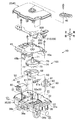
ハウジング20は、図2に示すように、樹脂製の箱体であり、前面34aからロックピン50が突出している。ハウジング20は、図3に示すように、内部空間が収容空間31になるハウジングロア30と、ハウジングロア30の開口部32を閉塞するハウジングアッパー40と、を備えている。ハウジングロア30とハウジングアッパー40とを組み合わせることで、ハウジング20内に収容空間31が形成される。
ハウジングロア30は、上面に開口部32が形成された箱状の部材である。ハウジングロア30は、平板状の底部33と、底部33の外周縁部に立設された周壁部34と、を有している。周壁部34は収容空間31を囲む枠であり、平面視で略四角形に形成されている。
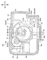
底部33は、平面視で略四角形に形成されている(図4参照)。底部33の右後部には、雄コネクタ35が下方に向けて突出している。雄コネクタ35には、駆動機構に電力を供給するための雌コネクタ(図示せず)が装着される。雌コネクタは、車両1(図1参照)に搭載された制御装置(図示せず)に電気的に接続される。
底部33は、平面視で略四角形に形成されている(図4参照)。底部33の右後部には、雄コネクタ35が下方に向けて突出している。雄コネクタ35には、駆動機構に電力を供給するための雌コネクタ(図示せず)が装着される。雌コネクタは、車両1(図1参照)に搭載された制御装置(図示せず)に電気的に接続される。
ハウジングロア30の周壁部34の前面34aには、充電口2aの壁部2b(図1参照)の内面に取り付けられる取付部36aが突設されている。また、ハウジングロア30の下面には、受電コネクタ3(図1参照)に取り付けられる左右二つのハウジング支持部36bが形成されている。
ハウジングロア30の開口縁部37(周壁部34の上端縁部)は、周壁部34の外面よりも外側にフランジ状に突出している。開口縁部37の上面には、無端状のシール部材(図示せず)が嵌め込まれるシール溝37aが全周に亘って形成されている(図4参照)。
ハウジングアッパー40は、ハウジングロア30の開口部32を閉塞するための平板状の蓋部材である。ハウジングアッパー40の外周形状は、ハウジングロア30の開口縁部37の外周形状と同じ形状に形成されている。
ハウジングアッパー40の外周縁部は、ハウジングロア30の開口縁部37に係合されるとともに、ホットメルト等の接着材によって開口縁部37に接着される。
また、ハウジングロア30の開口縁部37に設けられたシール部材(図示せず)によって、ハウジングロア30とハウジングアッパー40との間が液密にシールされる。
ハウジングアッパー40の外周縁部は、ハウジングロア30の開口縁部37に係合されるとともに、ホットメルト等の接着材によって開口縁部37に接着される。
また、ハウジングロア30の開口縁部37に設けられたシール部材(図示せず)によって、ハウジングロア30とハウジングアッパー40との間が液密にシールされる。
ハウジングロア30の開口部32には、板状のプレートインナー45が嵌め合わされる。プレートインナー45は、後記するロックピン50、駆動機構100の各部品および基板300を支持するものであり、周壁部34の内面に突設された支持部に支持される。
プレートインナー45の右側前部には、後記するスイッチ210,220を上下方向に挿通させるための切り欠き部45aが形成されている。
プレートインナー45の右側前部には、後記するスイッチ210,220を上下方向に挿通させるための切り欠き部45aが形成されている。
ロックピン50は、円形断面の軸部材であり、軸線方向が前後方向に配置されている。ロックピン50の前端部は半球面に形成されている。
図4に示すように、ロックピン50の後部は、ハウジングロア30の収容空間31に収容され、プレートインナー45に形成された軸受穴45b(図3参照)に挿通されている。また、ロックピン50の前部は、周壁部34の前面34aから外側に突出している。
図4に示すように、ロックピン50の後部は、ハウジングロア30の収容空間31に収容され、プレートインナー45に形成された軸受穴45b(図3参照)に挿通されている。また、ロックピン50の前部は、周壁部34の前面34aから外側に突出している。
ハウジングロア30の収容空間31には、図3に示すように、ロックピン50を前後方向(軸線方向)に進退させる駆動機構100と、ロックピン50の位置を検出するピン検出装置200と、基板300と、が収容される。
駆動機構100は、ロックピン50を保持するホルダ60と、カム73が突設されたカムギヤ72を有するカム部材70と、電動モータ80と、電動モータ80の出力軸81とカムギヤ72との間に介設される駆動伝達部材90と、を備えている。
カム部材70は、ホルダ60を前後方向に移動させるための部材である。カム部材70は、軸方向が上下方向に配置された回転軸71と、回転軸71を中心軸とする平歯車であるカムギヤ72と、カムギヤ72の下面に突設されたカム73と、を備えている。カム73は、カムギヤ72の回転中心に対して偏心している。
回転軸71の下部は、後記するカム収容枠62内に挿通されている(図4参照)。回転軸71の下端部は、ハウジングロア30の底面33aに回転自在に支持される。回転軸71の上部は、プレートインナー45に回転自在に支持されている。回転軸71の上端部は、ハウジングアッパー40の貫通穴を通じて外部に突出する。
カム73は、後記するホルダ60を前後方向に押し出す部位であり(図5および図6参照)、カムギヤ72の下面に突設されている。
カム73は、図4に示すように、平面視で略三角形の外周形状に形成されている。カム73の中心位置は回転軸71に対して右側に偏心している。
カム73は、図4に示すように、平面視で略三角形の外周形状に形成されている。カム73の中心位置は回転軸71に対して右側に偏心している。
カム部材70は、カム73の中心位置が回転軸71よりも右側の領域で、回転軸71の軸回りに約1/3回転の範囲で往復動するように、カムギヤ72の回転角度が設定されている。
カムギヤ72には、径方向の外方に突出したロッド74(特許請求の範囲における「被検出部材」)が形成されている(図3参照)。
カムギヤ72には、径方向の外方に突出したロッド74(特許請求の範囲における「被検出部材」)が形成されている(図3参照)。
電動モータ80は、モータハウジング82から出力軸81が突出している。出力軸81には円筒状のねじ歯車81aが外嵌される。
駆動伝達部材90は、図3に示すように、軸方向が上下方向に配置された回転軸91と、回転軸91を中心軸とするはすば歯車である下部ギヤ92と、回転軸91を中心軸とする平歯車である上部ギヤ93と、を備えている。
回転軸91の下端部は、ハウジングロア30の底面33aに回転自在に支持されている。回転軸91の上端部は、プレートインナー45に回転自在に支持される。
図4に示すように、下部ギヤ92は電動モータ80のねじ歯車81aに連結される。また、上部ギヤ93はカムギヤ72に連結される。
回転軸91の下端部は、ハウジングロア30の底面33aに回転自在に支持されている。回転軸91の上端部は、プレートインナー45に回転自在に支持される。
図4に示すように、下部ギヤ92は電動モータ80のねじ歯車81aに連結される。また、上部ギヤ93はカムギヤ72に連結される。
電動モータ80のねじ歯車81aを回転させると、その駆動力が下部ギヤ92に伝達され、駆動伝達部材90が軸回りに回転する。これにより、上部ギヤ93からカムギヤ72に駆動力が伝達される。そして、カムギヤ72が軸回りに回転することで、カム73が回転軸71の軸回りに回転するように構成されている。
ホルダ60は、ハウジングロア30の底面33a上に前後方向に移動自在に取り付けられている。
ホルダ60の前端面にロックピン50の後部が取り付けられ、ホルダ60の後部にはカム73が収容されるカム収容枠62が開口している。
カム収容枠62は、上下方向に開口しており、上側からカム73が挿入される。カム収容枠62の内周面は、カム73のカム面が当接するカム受け面となっている。
ホルダ60の右側面の前部には、右方に向けて突出したロッド64(特許請求の範囲における「被検出部材」)が形成されている(図3参照)。
ホルダ60の前端面にロックピン50の後部が取り付けられ、ホルダ60の後部にはカム73が収容されるカム収容枠62が開口している。
カム収容枠62は、上下方向に開口しており、上側からカム73が挿入される。カム収容枠62の内周面は、カム73のカム面が当接するカム受け面となっている。
ホルダ60の右側面の前部には、右方に向けて突出したロッド64(特許請求の範囲における「被検出部材」)が形成されている(図3参照)。
ホルダ60の前端面と周壁部34の内面との間には、弾性部材51が介設されている。弾性部材51はコイルばねであり、ロックピン50が挿通されている。なお、弾性部材51は、コイルばねに限定されるものではなく、ゴムや皿ばね等の各種の弾性部材を用いることができる。
また、ハウジングロア30の底面33aには、図8に示すように、ホルダ60およびカム部材70を底面33aに組み付けるときに、ホルダ60およびカム部材70の位置や向きを定めるためのマーク33b,33cが形成されている。
カム部材70側のマーク33bは、カムギヤ72のロッド74の輪郭を模写した線(図8において符号33bが指している太線部)である。また、ホルダ60側のマーク33cは、ホルダ60の後部の輪郭を模写した線(図8において符号33cが指している太線部)である。
両マーク33b,33cに合わせて、カム部材70およびホルダ60を底面33aに組み付けると、ホルダ60のカム収容枠62内に、カム部材70のカム73が収まるように構成されている。
カム部材70側のマーク33bは、カムギヤ72のロッド74の輪郭を模写した線(図8において符号33bが指している太線部)である。また、ホルダ60側のマーク33cは、ホルダ60の後部の輪郭を模写した線(図8において符号33cが指している太線部)である。
両マーク33b,33cに合わせて、カム部材70およびホルダ60を底面33aに組み付けると、ホルダ60のカム収容枠62内に、カム部材70のカム73が収まるように構成されている。
ホルダ60およびカム部材70を底面33aに組み付けるときには、まず、ホルダ60をマーク33cに合わせて底面33aに組み付ける。その後、カム部材70のロッド74をマーク33bに合わせて、カム部材70をホルダ60の上面に組み付けると、カム73がカム収容枠62内に入り込む。このように、両マーク33b,33cを利用することで、カム部材70およびホルダ60をスムーズに底面33aに組み付けることができる。
基板300は、図3に示すように、左右方向に幅広に形成されており(図5参照)、プレートインナー45の上面に載置される。本実施形態の基板300は、ハウジングロア30の開口部32内の前部および右側部に配置される。
基板300は、電動モータ80の駆動を制御するものであり、後記する二つのスイッチ210,220、電動モータ80および雄コネクタ35が電気的に接続される。
なお、図5および図6では、駆動機構100と両スイッチ210,220との位置関係を分かり易く示すために、プレートインナー45の図示を省略している。
基板300は、電動モータ80の駆動を制御するものであり、後記する二つのスイッチ210,220、電動モータ80および雄コネクタ35が電気的に接続される。
なお、図5および図6では、駆動機構100と両スイッチ210,220との位置関係を分かり易く示すために、プレートインナー45の図示を省略している。
アクチュエータ10では、図4に示すように、電動モータ80のねじ歯車81aを回転させると、その駆動力が駆動伝達部材90を介してカムギヤ72に伝達される。
図6に示すように、カムギヤ72を右回り(時計回り)に回転させると、カム73がカム収容枠62の前側の内周面に当接した状態で、カム73が前方に向けて回転移動し、カム73によってカム収容枠62が前方に押し出される。
これにより、ホルダ60が前方に移動し、ロックピン50が前方に進出して、ハウジング20に対するロックピン50の突出量が増加する。
このとき、弾性部材51(図4参照)が、ホルダ60と周壁部34との間で収縮し、ホルダ60に弾性部材51の弾発力が作用する。これにより、カム収容枠62の前側の内周面がカム73に接触した状態が保たれることで、ホルダ60およびロックピン50が安定するため、ロックピン50を所定の進出位置に精度良く停止させることができる。
図6に示すように、カムギヤ72を右回り(時計回り)に回転させると、カム73がカム収容枠62の前側の内周面に当接した状態で、カム73が前方に向けて回転移動し、カム73によってカム収容枠62が前方に押し出される。
これにより、ホルダ60が前方に移動し、ロックピン50が前方に進出して、ハウジング20に対するロックピン50の突出量が増加する。
このとき、弾性部材51(図4参照)が、ホルダ60と周壁部34との間で収縮し、ホルダ60に弾性部材51の弾発力が作用する。これにより、カム収容枠62の前側の内周面がカム73に接触した状態が保たれることで、ホルダ60およびロックピン50が安定するため、ロックピン50を所定の進出位置に精度良く停止させることができる。
なお、カム73の外周形状には、回転中心に対して一定の半径に形成された円弧状の領域が形成されている。カム73の回転角度において、前記した領域がカム収容枠62に接触している区間は、カム73が右回りに回転してもホルダ60が前方に押し出されない停留角(不感帯)であり、ロックピン50は停止した状態となる。
また、アクチュエータ10では、ロックピン50を進出させた状態から、図5に示すように、カムギヤ72を左回り(反時計回り)に回転させると、カム73が後方に向けて回転移動し、カム73がカム収容枠62の内周面を後方に押し出す。これにより、ロックピン50が後方に退行して、ハウジング20に対するロックピン50の突出量を減少させることができる。
第一実施形態では、カム73が後方に向けて回転したときに、弾性部材51(図4参照)の弾発力がホルダ60に作用し、カム収容枠62の前側の内周面がカム73に当接した状態で、カム73の回転に伴ってホルダ60が後方に移動する。このように、ロックピン50を退行させるときに、カム収容枠62の前側の内周面がカム73に接触した状態が保たれることで、ホルダ60およびロックピン50が安定する。そのため、ロックピン50を所定の退行位置に精度良く停止させることができる。
第一実施形態では、カム73が後方に向けて回転したときに、弾性部材51(図4参照)の弾発力がホルダ60に作用し、カム収容枠62の前側の内周面がカム73に当接した状態で、カム73の回転に伴ってホルダ60が後方に移動する。このように、ロックピン50を退行させるときに、カム収容枠62の前側の内周面がカム73に接触した状態が保たれることで、ホルダ60およびロックピン50が安定する。そのため、ロックピン50を所定の退行位置に精度良く停止させることができる。
図1に示すように、受電コネクタ3に充電コネクタ4が装着されたことを制御装置(図示せず)が検出した場合には、ロックピン50がハウジング20に対して進出し、ロックピン50の前部が充電コネクタ4のフック4bの上方に配置される。
これにより、フック4bの傾動がロックピン50によって規制され、フック4bは受電コネクタ3の係合突起3bに係合した状態に固定されるため、受電コネクタ3から充電コネクタ4が外れるのを防ぐことができる。
そして、ロックピン50の進出が停止した後に、充電装置(図示せず)から蓄電池(図示せず)への充電が開始される。
これにより、フック4bの傾動がロックピン50によって規制され、フック4bは受電コネクタ3の係合突起3bに係合した状態に固定されるため、受電コネクタ3から充電コネクタ4が外れるのを防ぐことができる。
そして、ロックピン50の進出が停止した後に、充電装置(図示せず)から蓄電池(図示せず)への充電が開始される。
また、充電後にロック解除信号が制御装置(図示せず)に入力されると、ロックピン50がハウジング20に対して退行し、ロックピン50の前部が充電コネクタ4のフック4bの上方から退去する。
これにより、フック4bが傾動可能となり、フック4bを受電コネクタ3の係合突起3bから離脱させて、受電コネクタ3から充電コネクタ4を引き抜くことができる。
これにより、フック4bが傾動可能となり、フック4bを受電コネクタ3の係合突起3bから離脱させて、受電コネクタ3から充電コネクタ4を引き抜くことができる。
また、図3に示すように、ハウジングアッパー40の上面には、カム部材70の回転軸71の上端部に取り付けられたロック解除用レバー42が設けられている(図2参照)。ロック解除用レバー42を回転させることで、カム部材70を手動で強制的に回転させ、ロックピン50を退行させることができる。
次に、第一実施形態のピン検出装置200について説明する。
ピン検出装置200は、図5に示すように、ロックピン50の前後方向の位置を検出するものである。ピン検出装置200は、進出側のスイッチ210(特許請求の範囲における「検出手段」)と、退行側のスイッチ220(特許請求の範囲における「検出手段」)と、を備えている。
ピン検出装置200は、図5に示すように、ロックピン50の前後方向の位置を検出するものである。ピン検出装置200は、進出側のスイッチ210(特許請求の範囲における「検出手段」)と、退行側のスイッチ220(特許請求の範囲における「検出手段」)と、を備えている。
両スイッチ210,220は、左右方向に並設されており、基板300の下面300b(図7(a)および(c)参照)の右側前部に取り付けられている。両スイッチ210,220は、基板300に対して電気的に接続されている。
第一実施形態では、左側に配置された進出側のスイッチ210の前部と、右側に配置された退行側のスイッチ220の後部とが左右方向に並設されている。
第一実施形態では、左側に配置された進出側のスイッチ210の前部と、右側に配置された退行側のスイッチ220の後部とが左右方向に並設されている。
両スイッチ210,220は、プレートインナー45の切り欠き部45aを通じて、プレートインナー45の下側に突出している。両スイッチ210,220は、ロックピン50、ホルダ60およびカムギヤ72の右方に配置されている。
進出側のスイッチ210は、図7(a)に示すように、基板300の下面300bに取り付けられる箱状のスイッチ本体210aと、スイッチ本体210aの下面に設けられた傾斜板210bと、を備えている。
スイッチ本体210aの下面の前部には、上下方向に進退自在な検出ピン210c(特許請求の範囲における「検出部」)が突出している。検出ピン210cは下方に向けて付勢されている。
傾斜板210bは、前端部が検出ピン210cの下端部に当接し、後端部はスイッチ本体210aの下面に対して上下方向に傾動自在に連結されている。傾斜板210bは上方に向けて付勢されており、傾斜板210の上面が検出ピン210cの下端部に常に接触している。
傾斜板210bは、前端部が検出ピン210cの下端部に当接し、後端部はスイッチ本体210aの下面に対して上下方向に傾動自在に連結されている。傾斜板210bは上方に向けて付勢されており、傾斜板210の上面が検出ピン210cの下端部に常に接触している。
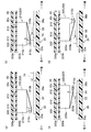
進出側のスイッチ210は、図7(b)に示すように、傾斜板210bが押し上げられて、検出ピン210cがスイッチ本体210aに対して所定量まで押し込まれると、基板300に検出信号を出力するように構成されている。
退行側のスイッチ220は、図7(c)および(d)に示すように、進行側のスイッチ210と同じ構造である。退行側のスイッチ220は、基板300の下面300bに取り付けられるスイッチ本体220aと、スイッチ本体220aの下面に設けられた傾斜板210bと、を備えている。
図5に示すように、進行側のスイッチ210と退行側のスイッチ220とは、スイッチ本体210a,220aが前後反対向きに配置されている。さらに、進行側のスイッチ210は、スイッチ本体210aの前部に検出ピン210cが配置されている。また、退行側のスイッチ220は、スイッチ本体220aの後部に検出ピン220cが配置されている。このように、両スイッチ210,220の検出ピン210c,220cが前後方向に間隔を空けて配置されている。また、両スイッチ210,220の検出ピン210c,220cは左右方向に並設されている。
ピン検出装置200では、図5および図6に示すように、進出側のスイッチ210はカム部材70のロッド74を検出するように構成されている。また、退行側のスイッチ220はホルダ60のロッド64を検出するように構成されている。
退行側のスイッチ220は、スイッチ本体220aの長手方向が前後方向となるように配置されている。
進行側のスイッチ210は、スイッチ本体210aの長手方向が、カム部材70のロッド74の移動軌跡の接線方向となるように、スイッチ本体220aは前部から後部に向かうに従って右側に傾斜している。そして、進行側のスイッチ210の右側後部が退行側のスイッチ220の後方に配置されている。
進行側のスイッチ210は、スイッチ本体210aの長手方向が、カム部材70のロッド74の移動軌跡の接線方向となるように、スイッチ本体220aは前部から後部に向かうに従って右側に傾斜している。そして、進行側のスイッチ210の右側後部が退行側のスイッチ220の後方に配置されている。
図6に示すように、カムギヤ72が右回り(時計回り)に回転し、ロッド74が前方に向けて移動したときには、図7(b)に示すように、ロッド74が進出側のスイッチ210の傾斜板210bの下面を前方に向けて摺動する。そして、ロッド74が前方に向かうに従って、ロッド74によって傾斜板210bが押し上げられ、検出ピン210cが押し込まれる。このとき、図7(d)に示すように、ホルダ60のロッド64は前方に向けて移動し、ロッド64は退行側のスイッチ220から離れた位置に配置される。
進出側のスイッチ210は、図6に示すように、ロックピン50が最も進出した状態となり、さらに、カム73の回転角度が停留角(不感帯)の中間位置に達したときに、基板300に検出信号を出力するように設定されている。このようにして、ピン検出装置200によって、ロックピン50が進出側の所定位置まで進出したことが検出されると、進出側のスイッチ210から検出信号が基板300を介して制御装置(図示せず)に出力される。そして、制御装置は出力軸81の回転を停止する。
図5に示すように、カムギヤ72が左回り(反時計回り)に回転し、ホルダ60が後方に向けて移動したときには、図7(c)に示すように、ロッド64が退行側のスイッチ220の傾斜板220bの下面を後方に向けて摺動する。そして、ロッド64が後方に向かうに従って、ロッド64によって傾斜板220bが押し上げられ、検出ピン220cが押し込まれる。
退行側のスイッチ220は、図5に示すように、ロックピン50が最も退行した状態となる位置まで移動したときに、基板300に検出信号を出力するように設定されている。このようにして、ピン検出装置200によって、ロックピン50が退行側の所定位置まで退行したことが検出されると、検出信号が退行側のスイッチ220から基板300を介して制御装置(図示せず)に出力される。そして、制御装置は出力軸81の回転を停止する。
プレートインナー45の下面45cには、図7(a)から(d)に示すように、基板300の上面300aを支持する複数の支持突起310が形成されている。
支持突起310は、スイッチ210,220の傾斜板210b,220bがロッド74,64によって押し上げられたときに、その押圧力によって基板300が上向きに撓むのを防ぐものである。
支持突起310の数や配置は限定されるものではなく、基板300の撓みを効果的に防ぐように、基板300の形状やスイッチ210,220の位置などを考慮して適宜に設定される。
支持突起310は、スイッチ210,220の傾斜板210b,220bがロッド74,64によって押し上げられたときに、その押圧力によって基板300が上向きに撓むのを防ぐものである。
支持突起310の数や配置は限定されるものではなく、基板300の撓みを効果的に防ぐように、基板300の形状やスイッチ210,220の位置などを考慮して適宜に設定される。
ハウジングロア30の底面33aには、カム部材70のロッド74を支持するガイドレール38aおよびホルダ60のロッド64を支持するガイドレール38bが突設されている(図4参照)。
カム部材70のロッド74を支持するガイドレール38aは、図4に示すように、ロッド74の移動軌跡に合わせて円弧状に湾曲している。そして、カム部材70が回転したときに、ロッド74がガイドレール38aの上面を摺動するように構成されている。
ホルダ60のロッド64を支持するガイドレール38bは、ロッド64の移動軌跡に合わせて前後方向に直線状に形成されている。そして、ホルダ60が前後方向に移動したときに、ロッド64がガイドレール38bの上面を摺動するように構成されている。
カム部材70のロッド74を支持するガイドレール38aは、図4に示すように、ロッド74の移動軌跡に合わせて円弧状に湾曲している。そして、カム部材70が回転したときに、ロッド74がガイドレール38aの上面を摺動するように構成されている。
ホルダ60のロッド64を支持するガイドレール38bは、ロッド64の移動軌跡に合わせて前後方向に直線状に形成されている。そして、ホルダ60が前後方向に移動したときに、ロッド64がガイドレール38bの上面を摺動するように構成されている。
以上のようなアクチュエータ10では、図5に示すように、二つのスイッチ210,220を左右方向に並設されているため、両スイッチ210,220の設置スペースの前後方向の長さ(ロックピン50の進退方向の長さ)を小さくすることができる。したがって、ハウジングロア30の前後方向の長さも小さくすることができ、ひいては、ハウジング20(図2参照)を小型化することができる。
また、アクチュエータ10では、図6に示すように、進出側のスイッチ210は、カムギヤ72のロッド74を検出しており、カム73がホルダ60を進出側に押し出したときに、カム73の回転角度(変位量)に基づいて、ロックピン50の位置を検出している。この構成では、ロックピン50を進出させたときに、ロックピン50の位置を精度良く検出することができる。
さらに、アクチュエータ10では、カム73の回転角度が停留角(不感帯)に達して、ロックピン50が最も進出した状態となった後に、カム73の回転角度が停留角の中間位置に達すると、進出側のスイッチ210がロッド74を検出するように構成されている。これにより、ロックピン50の位置の検出精度を容易に高めることができる。
また、図7(a)から(d)に示すように、基板300はプレートインナー45の支持突起310に支持されている。したがって、ロッド74,64によってスイッチ210,220の傾斜板210b,220bが押し上げられたときに、その押圧力によって基板300が上向きに撓むのを防ぐことができる。
さらに、カム部材70のロッド74およびホルダ60のロッド64は、ハウジングロア30の底面33aに突設された両ガイドレール38b,38cに支持されている。したがって、ロッド74,64がスイッチ210,220の傾斜板210b,220bを押し上げたときに、その反力によってロッド74,64が下向きに撓むのを防ぐことができる。
このように、基板300およびロッド74,64は、支持突起310およびガイドレール38a,38bによって支持されている。そのため、ロッド74,64によって、スイッチ210,220の傾斜板210b,220bを確実に押し上げることができ、ピン検出装置200の検出精度を高めることができる。
さらに、カム部材70のロッド74およびホルダ60のロッド64は、ハウジングロア30の底面33aに突設された両ガイドレール38b,38cに支持されている。したがって、ロッド74,64がスイッチ210,220の傾斜板210b,220bを押し上げたときに、その反力によってロッド74,64が下向きに撓むのを防ぐことができる。
このように、基板300およびロッド74,64は、支持突起310およびガイドレール38a,38bによって支持されている。そのため、ロッド74,64によって、スイッチ210,220の傾斜板210b,220bを確実に押し上げることができ、ピン検出装置200の検出精度を高めることができる。
以上、本発明の第一実施形態について説明したが、本発明は前記実施形態に限定されることなく、その趣旨を逸脱しない範囲で適宜に変更が可能である。
第一実施形態では、図6に示すように、進出側のスイッチ210はカム部材70のロッド74を検出し、退行側のスイッチ220はホルダ60のロッド64を検出している。しかし、カム部材70に二つのロッドを形成し、両スイッチ210,220がカム部材70の両ロッドをそれぞれ検出するように構成してもよい。
また、ホルダ60およびカム部材70のロッド74,64の形状は限定されるものではない。さらに、ロックピン50にロッドを形成してもよい。
第一実施形態では、図6に示すように、進出側のスイッチ210はカム部材70のロッド74を検出し、退行側のスイッチ220はホルダ60のロッド64を検出している。しかし、カム部材70に二つのロッドを形成し、両スイッチ210,220がカム部材70の両ロッドをそれぞれ検出するように構成してもよい。
また、ホルダ60およびカム部材70のロッド74,64の形状は限定されるものではない。さらに、ロックピン50にロッドを形成してもよい。
また、第一実施形態のスイッチ210,220は、図7(a)から(d)に示すように、傾斜板210b,220bによって、検出ピン210c,220cが押し込まれるように構成されているが、スイッチ210,220の構成は限定されるものではない。例えば、ロッド74,64によって検出ピン210c,220cを直接押し込むように構成してもよい。さらに、ロッド74,64(被検出部材)を検出する検出手段は、接触型のスイッチ210,220に限定されるものではなく、各種の検出手段を用いることができる。例えば、光センサ等の非接触型の検出手段を用いてもよい。
また、第一実施形態では、両スイッチ210,220のスイッチ本体210a,220aを前後反対向きに配置しているが、両スイッチ210,220のスイッチ本体210a,220aを前後同じ向きに配置してもよい。
また、第一実施形態では、基板300を支持するための支持突起310が、プレートインナー45の下面45cに突設されているが、ハウジングアッパー40(図3参照)の下面に支持突起を突設してもよい。
また、第一実施形態では、図1に示すように、受電コネクタ3から充電コネクタ4が外れるのを防ぐためのロック機構5に、本発明のアクチュエータを適用しているが、本発明のアクチュエータは各種のアクチュエータに適用可能である。
[第二実施形態]
第二実施形態のアクチュエータは、前記した第一実施形態のアクチュエータ10(図3参照)と略同様の構成であり、図9(a)および(b)に示すように、進出側のスイッチ210および退行側のスイッチ220の両方が、ホルダ60のロッド64を検出する点が異なっている。
第二実施形態のアクチュエータは、前記した第一実施形態のアクチュエータ10(図3参照)と略同様の構成であり、図9(a)および(b)に示すように、進出側のスイッチ210および退行側のスイッチ220の両方が、ホルダ60のロッド64を検出する点が異なっている。
第二実施形態のピン検出装置200Aでは、両スイッチ210,220のスイッチ本体210a,220a全体が左右方向に並設されている。また、スイッチ本体210a,220aは前後反対向きに配置されるとともに、両検出ピン210c,220cが前後方向に間隔を空けて配置されている。そして、前後の検出ピン210c,220cの間に、ホルダ60のロッド64が配置されている。
ピン検出装置200Aでは、図9(b)に示すように、ホルダ60が前方に移動したときには、進出側のスイッチ210によってロッド64が検出される。また、図9(a)に示すように、ホルダ60が後方に移動したときには、退行側のスイッチ220によってロッド64が検出される。
第二実施形態のアクチュエータでは、両スイッチ210,220が一つのロッド64を検出するため、二つのロッドを両スイッチ210,220がそれぞれ検出する場合に比べて、ロッドの移動領域を小さくすることができ、ハウジングを小型化することができる。
1 車両
2a 充電口
3 受電コネクタ
3b 係合突起
4 充電コネクタ
4b フック
5 ロック機構
10 アクチュエータ
20 ハウジング
30 ハウジングロア
31 収容空間
33a 底面
33b カム部材側のマーク
33c ホルダ側のマーク
34 周壁部
38a ガイドレール
38b ガイドレール
40 ハウジングアッパー
45 プレートインナー
50 ロックピン
60 ホルダ
62 カム収容枠
64 ロッド(被検出部材)
70 カム部材
72 カムギヤ
73 カム
74 ロッド(被検出部材)
90 駆動伝達部材
100 駆動機構
200 ピン検出装置(第一実施形態)
200A ピン検出装置(第二実施形態)
210 進出側のスイッチ(検出手段)
210a スイッチ本体
210b 傾斜板
210c 検出ピン(検出部)
220 退行側のスイッチ(検出手段)
220a スイッチ本体
220b 傾斜板
220c 検出ピン(検出部)
300 基板
310 支持突起
2a 充電口
3 受電コネクタ
3b 係合突起
4 充電コネクタ
4b フック
5 ロック機構
10 アクチュエータ
20 ハウジング
30 ハウジングロア
31 収容空間
33a 底面
33b カム部材側のマーク
33c ホルダ側のマーク
34 周壁部
38a ガイドレール
38b ガイドレール
40 ハウジングアッパー
45 プレートインナー
50 ロックピン
60 ホルダ
62 カム収容枠
64 ロッド(被検出部材)
70 カム部材
72 カムギヤ
73 カム
74 ロッド(被検出部材)
90 駆動伝達部材
100 駆動機構
200 ピン検出装置(第一実施形態)
200A ピン検出装置(第二実施形態)
210 進出側のスイッチ(検出手段)
210a スイッチ本体
210b 傾斜板
210c 検出ピン(検出部)
220 退行側のスイッチ(検出手段)
220a スイッチ本体
220b 傾斜板
220c 検出ピン(検出部)
300 基板
310 支持突起
Claims (4)
- 中空なハウジングと、前記ハウジングの外面から突出したピンと、を備えているアクチュエータであって、
前記ハウジング内には、
前記ピンを前後方向に進退させる駆動機構と、
前記ピンに連動して前後方向に移動する被検出部材と、
前記ピンの位置を検出するピン検出装置と、が収容され、
前記ピン検出装置は、
前記ピンが進出側の所定位置まで進出したときに、前記被検出部材を検出する進出側の検出手段と、
前記ピンが退行側の所定位置まで退行したときに、前記被検出部材を検出する退行側の検出手段と、を備え、
前記両検出手段は左右方向に並設されていることを特徴とするアクチュエータ。 - 前記駆動機構は、
前記ピンを保持するホルダと、
前記ホルダに当接するカムを有するカム部材と、を備え、
前記カム部材が回転することで、前記カムによって前記ホルダが前後方向に押し出されるように構成されており、
前記進出側の検出手段は、前記カム部材に設けられた前記被検出部材を検出することを特徴とする請求の範囲第1項に記載のアクチュエータ。 - 前記駆動機構は、前記ピンを保持するホルダを備え、
前記両検出手段は、前記ホルダに設けられた前記被検出部材を検出する検出部を有し、
前記両検出手段が前後反対向きに配置されるとともに、前記両検出手段の前記検出部が前後方向に間隔を空けて配置されており、
前記両検出部の間に前記被検出部材が配置されていることを特徴とする請求の範囲第1項に記載のアクチュエータ。 - 前記両検出手段は、前記ハウジング内に収容された基板の一方の面に取り付けられ、
前記被検出部材は、前記基板の一方側に配置され、かつ前記被検出部材は前記両検出手段に接触するように構成されており、
前記ハウジング内には、前記基板の他方の面を支持する支持突起が形成されていることを特徴とする請求の範囲第1項から請求の範囲第3項のいずれか一項に記載のアクチュエータ。
Applications Claiming Priority (2)
| Application Number | Priority Date | Filing Date | Title |
|---|---|---|---|
| JP2012269372A JP6082583B2 (ja) | 2012-12-10 | 2012-12-10 | アクチュエータ |
| JP2012-269372 | 2012-12-10 |
Publications (1)
| Publication Number | Publication Date |
|---|---|
| WO2014092020A1 true WO2014092020A1 (ja) | 2014-06-19 |
Family
ID=50934311
Family Applications (1)
| Application Number | Title | Priority Date | Filing Date |
|---|---|---|---|
| PCT/JP2013/082852 Ceased WO2014092020A1 (ja) | 2012-12-10 | 2013-12-06 | アクチュエータ |
Country Status (2)
| Country | Link |
|---|---|
| JP (1) | JP6082583B2 (ja) |
| WO (1) | WO2014092020A1 (ja) |
Cited By (2)
| Publication number | Priority date | Publication date | Assignee | Title |
|---|---|---|---|---|
| JP2017108614A (ja) * | 2015-11-25 | 2017-06-15 | ジョンソン エレクトリック ソシエテ アノニム | モータ駆動組立体 |
| EP3252879A1 (en) * | 2016-05-31 | 2017-12-06 | TE Connectivity Germany GmbH | Actuator module for charge inlets |
Families Citing this family (1)
| Publication number | Priority date | Publication date | Assignee | Title |
|---|---|---|---|---|
| JP7105557B2 (ja) | 2017-11-27 | 2022-07-25 | Ntn株式会社 | 電動アクチュエータ |
Citations (3)
| Publication number | Priority date | Publication date | Assignee | Title |
|---|---|---|---|---|
| JP2009228274A (ja) * | 2008-03-21 | 2009-10-08 | Hi-Lex Corporation | アクチュエータ |
| JP2011238530A (ja) * | 2010-05-12 | 2011-11-24 | Tokai Rika Co Ltd | 給電プラグロック装置 |
| JP2012181985A (ja) * | 2011-03-01 | 2012-09-20 | Aisin Seiki Co Ltd | 充電ケーブルユニットのロック装置 |
Family Cites Families (5)
| Publication number | Priority date | Publication date | Assignee | Title |
|---|---|---|---|---|
| JPS54103505A (en) * | 1978-02-01 | 1979-08-15 | Daikoku Denki Kk | Power transmitter for motor |
| JPH0736220Y2 (ja) * | 1986-06-09 | 1995-08-16 | 株式会社三協精機製作所 | モ−タ式アクチユエ−タ |
| JPH01105668U (ja) * | 1988-01-08 | 1989-07-17 | ||
| WO2003077410A1 (en) * | 2002-03-11 | 2003-09-18 | Seiko Epson Corporation | Rotation/movement converting actuator |
| JP5535602B2 (ja) * | 2009-12-01 | 2014-07-02 | 株式会社ミツバ | リニアアクチュエータ |
-
2012
- 2012-12-10 JP JP2012269372A patent/JP6082583B2/ja active Active
-
2013
- 2013-12-06 WO PCT/JP2013/082852 patent/WO2014092020A1/ja not_active Ceased
Patent Citations (3)
| Publication number | Priority date | Publication date | Assignee | Title |
|---|---|---|---|---|
| JP2009228274A (ja) * | 2008-03-21 | 2009-10-08 | Hi-Lex Corporation | アクチュエータ |
| JP2011238530A (ja) * | 2010-05-12 | 2011-11-24 | Tokai Rika Co Ltd | 給電プラグロック装置 |
| JP2012181985A (ja) * | 2011-03-01 | 2012-09-20 | Aisin Seiki Co Ltd | 充電ケーブルユニットのロック装置 |
Cited By (3)
| Publication number | Priority date | Publication date | Assignee | Title |
|---|---|---|---|---|
| JP2017108614A (ja) * | 2015-11-25 | 2017-06-15 | ジョンソン エレクトリック ソシエテ アノニム | モータ駆動組立体 |
| EP3252879A1 (en) * | 2016-05-31 | 2017-12-06 | TE Connectivity Germany GmbH | Actuator module for charge inlets |
| US10220714B2 (en) | 2016-05-31 | 2019-03-05 | Te Connectivity Germany Gmbh | Actuator module for charge inlets |
Also Published As
| Publication number | Publication date |
|---|---|
| JP2014117074A (ja) | 2014-06-26 |
| JP6082583B2 (ja) | 2017-02-15 |
Similar Documents
| Publication | Publication Date | Title |
|---|---|---|
| JP5953221B2 (ja) | アクチュエータ | |
| CN109987063B (zh) | 水平装取电池的换电设备及电池拆卸、安装方法 | |
| CN109072643B (zh) | 进退移动装置 | |
| US9132060B2 (en) | Medicine feeder | |
| US9350118B2 (en) | Charging port locking device | |
| US8098042B2 (en) | Charging system for walking robot and charging method therefor | |
| CN103596819B (zh) | 电池更换机器人 | |
| CN108631122B (zh) | 致动器 | |
| CN212685310U (zh) | 解锁装置及包含其的换电设备 | |
| CN107109873A (zh) | 进退移动装置 | |
| CN106054382A (zh) | 抬头显示装置 | |
| JP6082583B2 (ja) | アクチュエータ | |
| WO2022007812A1 (zh) | 解锁装置、包含其的换电设备、解锁控制方法 | |
| CN113895287B (zh) | 解锁装置及包含其的换电设备 | |
| JP6811128B2 (ja) | アクチュエータ | |
| US20250172022A1 (en) | Lid opening and closing device | |
| CN107531185A (zh) | 车辆用电动收纳式视觉辨认装置 | |
| CN213705146U (zh) | 锁基座和锁止机构 | |
| WO2014098090A1 (ja) | アクチュエータ | |
| CN113400915B (zh) | 锁止装置、托架总成、电动汽车及电池箱的锁止方法 | |
| JP2020122335A (ja) | 進退移動装置 | |
| JP4245451B2 (ja) | 車載機器用のパネル駆動装置 | |
| JP2020186608A (ja) | リッドロック装置 | |
| CN104648315B (zh) | 电动转向锁定装置 | |
| US20190077317A1 (en) | Vehicle visual recognition device |
Legal Events
| Date | Code | Title | Description |
|---|---|---|---|
| 121 | Ep: the epo has been informed by wipo that ep was designated in this application |
Ref document number: 13861628 Country of ref document: EP Kind code of ref document: A1 |
|
| NENP | Non-entry into the national phase |
Ref country code: DE |
|
| 122 | Ep: pct application non-entry in european phase |
Ref document number: 13861628 Country of ref document: EP Kind code of ref document: A1 |