WO2014091577A1 - 光通信装置、および電子部品装着装置 - Google Patents
光通信装置、および電子部品装着装置 Download PDFInfo
- Publication number
- WO2014091577A1 WO2014091577A1 PCT/JP2012/082167 JP2012082167W WO2014091577A1 WO 2014091577 A1 WO2014091577 A1 WO 2014091577A1 JP 2012082167 W JP2012082167 W JP 2012082167W WO 2014091577 A1 WO2014091577 A1 WO 2014091577A1
- Authority
- WO
- WIPO (PCT)
- Prior art keywords
- inclination
- light intensity
- optical axis
- sensor
- optical
- Prior art date
- Legal status (The legal status is an assumption and is not a legal conclusion. Google has not performed a legal analysis and makes no representation as to the accuracy of the status listed.)
- Ceased
Links
Images




Classifications
-
- G—PHYSICS
- G01—MEASURING; TESTING
- G01C—MEASURING DISTANCES, LEVELS OR BEARINGS; SURVEYING; NAVIGATION; GYROSCOPIC INSTRUMENTS; PHOTOGRAMMETRY OR VIDEOGRAMMETRY
- G01C9/00—Measuring inclination, e.g. by clinometers, by levels
- G01C9/02—Details
- G01C9/06—Electric or photoelectric indication or reading means
-
- G—PHYSICS
- G01—MEASURING; TESTING
- G01C—MEASURING DISTANCES, LEVELS OR BEARINGS; SURVEYING; NAVIGATION; GYROSCOPIC INSTRUMENTS; PHOTOGRAMMETRY OR VIDEOGRAMMETRY
- G01C25/00—Manufacturing, calibrating, cleaning, or repairing instruments or devices referred to in the other groups of this subclass
-
- H—ELECTRICITY
- H04—ELECTRIC COMMUNICATION TECHNIQUE
- H04B—TRANSMISSION
- H04B10/00—Transmission systems employing electromagnetic waves other than radio-waves, e.g. infrared, visible or ultraviolet light, or employing corpuscular radiation, e.g. quantum communication
- H04B10/11—Arrangements specific to free-space transmission, i.e. transmission through air or vacuum
- H04B10/114—Indoor or close-range type systems
- H04B10/1143—Bidirectional transmission
-
- H—ELECTRICITY
- H05—ELECTRIC TECHNIQUES NOT OTHERWISE PROVIDED FOR
- H05K—PRINTED CIRCUITS; CASINGS OR CONSTRUCTIONAL DETAILS OF ELECTRIC APPARATUS; MANUFACTURE OF ASSEMBLAGES OF ELECTRICAL COMPONENTS
- H05K13/00—Apparatus or processes specially adapted for manufacturing or adjusting assemblages of electric components
- H05K13/08—Monitoring manufacture of assemblages
- H05K13/0882—Control systems for mounting machines or assembly lines, e.g. centralized control, remote links, programming of apparatus and processes as such
Definitions
- the present invention relates to an optical communication device and an electronic component mounting device, and more particularly to drift correction of a tilt sensor provided in the optical communication device.
- an angle sensor is fixed to one end of a rotating shaft of a holder so that the inclination of a half mirror can be detected, and an actuator is fixed to the other end, The inclination of the half mirror can be varied by driving.
- an angle sensor is built in, and a technique is disclosed in which the position can be controlled based on not only the output signal of the position detection element but also the detection result of the angle sensor, and the irradiation position can be corrected. (Patent Document 1, etc.).
- an optical communication device is a device that performs signal transmission between a mobile device and a control device by wireless transmission using an optical signal.
- One is movably provided in a mobile device such as a slide mechanism, and the other is provided in a control device. It is done.
- the optical communication device on the mobile device side is provided with an actuator for adjusting the inclination.
- an inclination sensor for detecting the inclination of the optical communication device is provided to control the actuator. This tilt sensor outputs a sensor tilt value indicating the tilt as a tilt reference value when the tilt is 0 degree.
- the sensor tilt value can be obtained even when communication light deviates from the optical axis.
- the optical axis can be made to coincide again by driving the actuator according to the above.
- the inclination reference value varies due to temperature drift and other factors. For example, when the characteristics of the tilt sensor fluctuate due to the temperature difference of the tilt sensor, there is a problem that an accurate sensor tilt value cannot be obtained.
- the background art described in Patent Document 1 merely discloses a technique that can control the angle based on the detection result of the angle sensor. That is, the background art described in Patent Document 1 has no description regarding the temperature drift of the inclination reference value applied to the inclination sensor provided in the optical communication apparatus. Therefore, in the background art described in Patent Document 1, there is no description regarding correction of temperature drift, and when the tilt reference value varies due to temperature drift, an accurate sensor tilt value cannot be obtained after the variation. There are challenges.
- an object of the present invention is to provide an optical communication device and an electronic component mounting device capable of adjusting the optical axis of communication light in optical wireless communication.
- the optical communication device includes a light receiving unit, a tilt sensor, a light intensity decrease detection unit, an optical axis tilt detection unit, And drift correction means.
- the light receiving unit receives the communication light and detects the light intensity of the communication light.
- the tilt sensor detects the tilt of the optical axis of the communication light received by the light receiving unit.
- the light intensity decrease detecting means detects that the light intensity detected by the light receiving unit has decreased below a predetermined light intensity.
- the optical axis inclination detecting means detects that the inclination of the optical axis detected by the inclination sensor is inclined more than a predetermined angle.
- the drift correction means is not detected when the light intensity drop detection means detects that the light intensity is less than or equal to a predetermined light intensity, and the optical axis inclination detection means detects that the inclination of the optical axis is greater than or equal to a predetermined angle (first detection state). Drift correction is performed on the tilt sensor.
- the optical communication device is the optical communication device according to claim 1, wherein the light intensity is detected to be equal to or less than a predetermined light intensity by the light intensity decrease detection unit, and the optical axis inclination detection unit detects the optical axis.
- the inclination is detected to be equal to or greater than a predetermined angle (second detection state)
- drift correction is performed on the inclination sensor.
- the optical communication device is the optical communication device according to claim 2, wherein the drift detection unit continues the drift correction for a predetermined time, and the first detection state or the second When the detection state continues, the communication light emission is stopped.
- the optical communication device is the optical communication device according to any one of claims 1 to 3, wherein the drift correction means is an average value of the inclination of the optical axis sampled every predetermined period. , And the drift correction is performed using the difference between the calculated average value and the inclination reference value as a fluctuation value due to temperature drift.
- an optical communication device is the optical communication device according to any one of claims 1 to 4, further comprising an actuator for adjusting an inclination of an optical axis.
- the actuator is driven.
- the light intensity of the communication light received by the light receiving unit is greater than the predetermined light intensity, but the inclination of the optical axis of the communication light is predetermined.
- drift correction is performed on the tilt sensor. If the light intensity is greater than the predetermined light intensity, the optical axis of the communication light is adjusted to a normal angle range.
- the optical axis tilt is detected to be greater than or equal to a predetermined angle despite the optical axis angle being in the normal angle range (first detection state)
- the output value of the tilt sensor varies due to temperature drift. It shows that.
- the drift due to the temperature drift of the tilt sensor can be eliminated by correcting the temperature drift by the drift correcting means.
- the optical communication device when the light intensity of the communication light received by the light receiving unit is detected to be equal to or lower than the predetermined light intensity and the inclination of the optical axis of the communication light is smaller than the predetermined angle (second detection state) ), Drift correction is performed on the tilt sensor. If the light intensity is less than or equal to the predetermined light intensity, the optical axis of the communication light is out of the normal angular range. When it is detected that the tilt of the optical axis is smaller than the predetermined angle even though the angle of the optical axis is outside the normal angle range (second detection state), the output value of the tilt sensor varies due to temperature drift. It shows that you are doing. When the second detection state is detected, the drift due to the temperature drift of the tilt sensor can be eliminated by correcting the temperature drift by the drift correcting means.
- the first and second detection states which are abnormal states, are not resolved despite the temperature drift correction for the tilt sensor. In this case, it is determined that some abnormality has occurred in the apparatus, and the emission of communication light is stopped. Thereby, the operation of the apparatus in an abnormal state can be prevented.
- the average value of the inclination of the optical axis sampled every predetermined period is calculated.
- the average value indicates the inclination of the optical axis in the stationary state.
- the tilt reference value indicates the tilt of the optical axis when the apparatus is stationary with no temperature drift. Therefore, the difference between the calculated average value and the inclination reference value can be a fluctuation value due to temperature drift, and drift correction can be performed based on this. Even in a state where the device vibrates during operation, it can be adjusted to a state where there is no fluctuation due to temperature drift.
- the actuator is driven to adjust the inclination of the optical axis.
- the optical intensity of the communication light can be adjusted to be equal to or higher than the predetermined optical intensity to maintain optical radio.
- FIG. 3 is a diagram schematically showing the optical communication device 1 when an X-axis slider 54 is viewed from the + Y direction in FIG. 2. It is a graph which shows together the correlation of light intensity (P), the inclination of optical axis AX, and the sensor output value (R) which shows the shift
- 5 is a flowchart showing a startup process of the optical communication device 1, an inclination adjustment process of the optical axis AX, and a drift correction process. It is a flowchart of the subroutine of step S32.
- mounting apparatus an electronic component mounting apparatus (hereinafter sometimes referred to as “mounting apparatus”) will be described as an example of an apparatus to which the optical communication apparatus of the present application is applied.
- the mounting device 10 includes a device main body 11, a pair of display devices 13 provided integrally with the device main body 11, and supply devices 15 and 16 provided detachably with respect to the device main body 11. Is provided.
- the mounting device 10 is an electronic component (not shown) with respect to the circuit board 100 transported by the transport device 21 housed in the device body 11 based on the control of the control device 80 shown in FIG. It is an apparatus which implements mounting work.
- the direction in which the circuit board 100 is transported by the transport device 21 (the left-right direction in FIG. 2) is the X-axis direction
- the horizontal direction in the transport direction of the circuit board 100 is the X-axis direction.
- a direction perpendicular to the direction is referred to as a Y-axis direction and will be described.
- the device body 11 includes display devices 13 at both ends in the Y-axis direction on one end side in the X-axis direction. Each display device 13 is a touch panel display device, and displays information related to the mounting operation of the electronic component. Further, the apparatus main body 11 includes supply devices 15 and 16 that are mounted so as to be sandwiched from both sides in the Y-axis direction.
- the supply device 15 is a feeder-type supply device, and includes a plurality of tape feeders 15A that are housed in a state where various electronic components are taped and wound on a reel.
- the supply device 16 is a tray-type supply device, and has a plurality of component trays 16A (see FIG. 2) on which a plurality of electronic components are placed.
- FIG. 2 is a schematic plan view showing the mounting apparatus 10 from the upper (upper side in FIG. 1) viewpoint with the upper cover 11A (see FIG. 1) of the apparatus main body 11 removed.
- the apparatus main body 11 includes the transport device 21, a mounting head 22 for mounting electronic components on the circuit board 100, and a moving device 23 for moving the mounting head 22. Prepare for the top.
- the transfer device 21 is provided in a substantially central portion of the base 20 in the Y-axis direction, and moves the pair of conveyor belts 31, the substrate holding device 32 held on the conveyor belt 31, and the substrate holding device 32. And an electromagnetic motor 33.
- the substrate holding device 32 holds the circuit board 100.
- the output shaft of the electromagnetic motor 33 is drivingly connected to the conveyor belt 31.
- the electromagnetic motor 33 is, for example, a servo motor that can control the rotation angle.
- the circuit board 100 moves in the X-axis direction together with the substrate holding device 32 when the conveyor belt 31 rotates around based on the driving of the electromagnetic motor 33.
- the mounting head 22 has a suction nozzle 41 that sucks electronic components on the lower surface facing the circuit board 100.
- the suction nozzle 41 communicates with the negative pressure air and the positive pressure air passage via a positive / negative pressure supply device 42 (see FIG. 3), sucks and holds the electronic component with the negative pressure, and supplies a slight positive pressure.
- the held electronic component is removed.
- the mounting head 22 has a nozzle lifting device 43 (see FIG. 3) that lifts and lowers the suction nozzle 41 and a nozzle rotation device 44 (see FIG. 3) that rotates the suction nozzle 41 about its axis. The vertical position of the electronic component to be held and the holding posture of the electronic component are changed.
- the nozzle lifting / lowering device 43 includes, for example, an electromagnetic motor 43A (see FIG. 3) as a drive source.
- the mounting head 22 has a position detection sensor 45 (see FIG. 3) for detecting the position of the electronic component to be held in the vertical direction. Further, a mark camera 47 for photographing the circuit board 100 is fixed to the mounting head 22 in a state of facing downward.
- the suction nozzle 41 is detachable from the mounting head 22 and can be changed according to the size and shape of the electronic component.
- the mounting head 22 is moved to an arbitrary position on the base 20 by the moving device 23.
- the moving device 23 includes an X-axis direction slide mechanism 50 for moving the mounting head 22 in the X-axis direction, and a Y-axis direction slide mechanism 52 for moving the mounting head 22 in the Y-axis direction.
- the X-axis direction slide mechanism 50 has an X-axis slider 54 provided on the base 20 so as to be movable in the X-axis direction, and an electromagnetic motor 56 as a drive source.
- the X-axis slider 54 moves to an arbitrary position in the X-axis direction based on driving of the electromagnetic motor 56.
- the X-axis slider 54 includes an actuator 7 described later and an active mass damper 9.
- the Y-axis direction slide mechanism 52 has a Y-axis slider 58 provided on the side surface of the X-axis slider 54 so as to be movable in the Y-axis direction, and an electromagnetic motor 60 as a drive source.
- the Y-axis slider 58 moves to an arbitrary position in the Y-axis direction based on driving of the electromagnetic motor 60.
- the mounting head 22 is attached to the Y-axis slider 58 and moves to an arbitrary position on the base 20 as the moving device 23 is driven. Thereby, the mark camera 47 can image the surface of an arbitrary position of the circuit board 100 by moving the mounting head 22. Image data photographed by the mark camera 47 is processed by the image processing device 71 (see FIG. 3) and output to the control device 80.
- the mounting head 22 is attached to the Y-axis slider 58 via the connector 48 and can be attached and detached with a single touch, and can be changed to a different type of work head, for example, a dispenser head.
- the base 20 has supply devices 15 and 16 connected to side portions provided on both sides in the Y-axis direction.
- the supply devices 15 and 16 can be attached to and detached from the base 20 in order to cope with a shortage of electronic components to be supplied, changes in the types of electronic components, and the like.
- the base 20 is provided with a parts camera 73 at a substantially central portion in the X-axis direction at a portion to which the supply devices 15 and 16 are connected.
- Each part camera 73 is provided in a state of facing upward, and images the electronic component sucked and held by the suction nozzle 41 of the mounting head 22 from each of the supply devices 15 and 16.
- the parts camera 73 outputs the captured image data to the image processing device 71 (see FIG. 3).
- the image processing device 71 outputs the processed data to the control device 80.
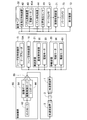
- the mounting apparatus 10 uses optical wireless multiplexed communication for data communication between the control apparatus 80 of the mounting apparatus 10 and parts (various apparatuses) other than the control apparatus 80. Is used.
- the configuration of the mounting apparatus 10 illustrated in FIG. 3 is an example in the case where the optical communication apparatuses 1 and 3 are applied, and is appropriately changed according to the type and number of apparatuses provided in the mounting apparatus 10.
- the optical communication devices 1 and 3 of the present application are systems that can be applied to an automatic machine operating in various production lines in addition to the electronic component mounting device exemplified by the mounting device 10.
- the control device 80 includes a controller 82 mainly composed of a computer having a CPU, ROM, RAM, and the like, an image board 84, a drive control board 85, and an I / O board 86.
- the controller 82 communicates with various devices via the boards 84, 85, 86.
- Each board 84, 85, 86 is connected to one end of the transmission path 2 via the optical communication device 3, and the other end of the transmission path 2 is connected to various devices (camera, motor, sensor, etc.) via the optical communication device 1. ) Is connected.
- Data input / output between the boards 84, 85, 86 and various devices is transmitted via the optical communication devices 1, 3 by optical wireless communication in the transmission path 2.
- the moving device 23 is provided with the optical communication device 1 facing the optical communication device 3 connected to the control device 80. Thereby, various communications are possible between the optical communication apparatuses 1 and 3.
- the image board 84 shown in FIG. 3 is a board that controls input / output of image data.
- the controller 82 uses the image board 84 to hold information (type, shape, etc.) on the circuit board 100 detected by the image processing apparatus 71 from processing of the image data of the mark camera 47 and hold the circuit board 100 by the board holding device 32. Receive information such as position error.
- the drive control board 85 is a board that controls input / output of operation commands for the electromagnetic motor and information fed back from the electromagnetic motor in real time.
- the controller 82 receives servo control information such as torque information and position information (vertical position of the electronic component held by the suction nozzle 41) acquired by the electromagnetic motor 43A via the drive control board 85.
- the I / O board 86 is a board that controls input / output of an output signal of the position detection sensor 45, for example.
- Data input from these devices to the control device 80 is multiplexed by the optical communication device 1 and then transmitted through the transmission path 2 as an optical wireless signal.
- the optical communication device 3 performs a process of demultiplexing the transmitted multiplexed signal and separating it into individual data. Of the separated data, the optical communication device 3 transfers the image data to the image board 84, the servo control information to the drive control board 85, and the I / O signal to the I / O board 86.
- the controller 82 processes each data received by the optical communication device 3. For example, the controller 82 outputs a control signal for the electromagnetic motor 43 ⁇ / b> A based on the processing result to the optical communication device 3 via the drive control board 85.
- the optical communication device 1 transfers the control signal transmitted from the optical communication device 3 to the nozzle lifting / lowering device 43.
- the electromagnetic motor 43A operates based on the control signal.
- the controller 82 outputs a control signal for changing the display of the display device 13 to the display device 13 via the I / O board 86, the optical communication device 3, and the optical communication device 1.
- control device 80 various types of information transmitted / received between the control device 80 and each device other than the control device 80 are transmitted / received as data multiplexed on the transmission line 2, for example, time division multiplexing (TDM) frame data.
- TDM time division multiplexing
- only part of the communication between the control device 80 and another device may be performed by optical wireless communication.
- an electronic component is mounted on the circuit board 100 held by the substrate holding device 32 by the mounting head 22.
- the controller 82 drives the transport device 21 to transport the circuit board 100 to the working position, stops the electromagnetic motor 33, and holds the circuit board 100 in a fixed manner.
- the controller 82 drives the moving device 23 to move the mounting head 22 onto the circuit board 100 and images the circuit board 100 with the mark camera 47.
- the controller 82 determines the type of the circuit board received from the image processing apparatus 71 and the error in the holding position of the circuit board 100.
- the controller 82 drives the supply devices 15 and 16 having electronic components in accordance with the determination result for the type of board, and performs control to send the corresponding electronic components to the supply position to the mounting head 22.
- the controller 82 drives the moving device 23 to suck and hold the electronic component conveyed at the supply position by the suction nozzle 41 of the mounting head 22.
- the controller 82 moves the mounting head 22 holding the electronic component onto the parts camera 73 to image the state of the electronic component. At this time, the controller 82 acquires an error in the holding position of the electronic component based on the imaging result. Next, the controller 82 moves the mounting head 22 to the mounting position on the circuit board 100 and rotates the suction nozzle 41 based on the holding position error between the circuit board and the electronic component, and then mounts the electronic component on the circuit board 100. .
- FIG. 4 is a diagram schematically showing the optical communication apparatus 1 when the X-axis slider 54 is viewed from the ⁇ Y direction of FIG.
- the Z direction is the vertical direction of the apparatus.
- the optical communication device 1, the tilt sensor 5, the actuator 7, and the active mass damper 9 are provided on the X-axis slider 54. Since the optical communication device 1 is provided in the X-axis slider 54, in the operating state, the displacement of the optical axis AX from the optical communication device 3 and the vibration of the optical communication device 1 due to the movement of the X-axis slider 54 are caused. It may occur.
- the optical axis AX that connects the optical communication device 1 and the optical communication device 3 is such that the communication light received and emitted by the light emitting and receiving unit 1A of the optical communication device 1 has sufficient light intensity for communication.
- the tilt sensor 5, the actuator 7, and the active mass damper 9 are used so that the tilt can be secured.
- the optical communication device 1 includes a light emitting / receiving element 1A and a control unit 1B.
- the light emitting / receiving element 1A includes a light receiving element such as a photodiode that receives communication light and a light emitting element such as a laser diode that emits communication light.
- the inclination of the optical axis AX is adjusted so that the light intensity of the communication light that is received and emitted is sufficient to ensure reliable communication.
- the photodiode which is a light receiving element, passes a current having an amount corresponding to the light intensity (P) of communication light (FIG. 5).
- the control unit 1B detects the light intensity (P) of incident communication light from the amount of flowing current.
- the control unit 1B processes signals input from the light emitting / receiving element 1A and the tilt sensor 5, and controls the actuator 7 and the active mass damper 9 based on the processing result. Further, the control unit 1B includes a nonvolatile memory (not shown) such as a flash memory, a light intensity threshold value PL1 (FIG. 5) that is a threshold value of light intensity (P) described later, and a sensor output described later.
- a nonvolatile memory such as a flash memory
- a light intensity threshold value PL1 (FIG. 5) that is a threshold value of light intensity (P) described later
- An inclination threshold value RL (FIG. 5), which is a threshold value of value (R) (FIG. 5), is stored.
- the tilt sensor 5 detects displacement caused by vibration in the Z direction of the X-axis slider 54.
- the tilt sensor 5 includes a gyro sensor (not shown).
- the gyro sensor detects the angular velocity.
- the tilt sensor 5 detects a sensor output value (R) by time-integrating a voltage value indicating an angular velocity, which is an output from the gyro sensor.
- the gyro sensor can also detect angular velocities in three directions of X, Y, and Z.
- the control unit 1B detects displacement due to vibration in each direction.
- the sensor output value (R) has a temperature drift as described later in FIG. 5 (sensor output value characteristic lines RA, RB, RC).
- the actuator 7 adjusts the inclination of the optical axis AX by adjusting the attitude of the optical communication device 1 under the control of the control unit 1B, so that communication light with sufficient light intensity enters the light emitting / receiving surface of the light emitting / receiving element 1A. Driven to output.
- the active mass damper 9 relieves vibration generated in the X-axis slider 54 under the control of the control unit 1B.
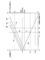
- FIG. 5 is a graph showing the correlation between the light intensity (P) and the inclination ( ⁇ ) of the optical axis AX, and the correlation between the sensor output value (R) indicating the deviation in the Z direction and the inclination ( ⁇ ) of the optical axis AX. is there.
- the former will be described as the light intensity characteristic line PW, and the latter as the sensor output value characteristic lines RA, RB, RC.
- the X axis is the inclination ( ⁇ ) of the optical axis AX, which is an inclination generated in accordance with the displacement in the Z direction shown in FIG.
- the Y1 axis indicates the light intensity (P) of communication light received by the light emitting / receiving element 1A.
- the light intensity characteristic line PW shows a correlation in which the light intensity (P) decreases as the inclination ( ⁇ ) of the optical axis AX increases.
- the light intensity value P0 is the value with the highest light intensity (P).
- the light intensity value when the inclination ( ⁇ ) of the optical axis AX is zero is shown.
- optical radio is performed with the normal light intensity (P).
- the light intensity threshold value PL2 is a minimum light intensity (P) that satisfies a predetermined communication quality in optical radio.
- the Y2 axis indicates the sensor output value (R) detected by the tilt sensor 5.
- the sensor output value characteristic line RA does not include temperature drift, and the sensor output value characteristic lines RB and RC include temperature drift.
- the sensor output value characteristic line RB includes a positive temperature drift, and the sensor output value characteristic line RC includes a negative temperature drift.
- the inclination reference value R0 is the inclination ( ⁇ ) of the optical axis AX when the optical communication apparatus 1 is stationary in a state where there is no temperature drift, and is a reference value of the sensor output value stored in the control unit 1B.
- the inclination reference values RA0, RB0, RC0 indicate sensor output values output by the inclination sensor 5 at the respective sensor output value characteristic lines RA, RB, RC when the actual inclination ( ⁇ ) of the optical axis AX is zero. .
- the slope reference value RA0 matches the slope reference value R0.
- the inclination reference value RB0 is output with a larger inclination than the inclination reference value R0
- the inclination reference value RC0 is output with a slope smaller than the slope reference value R0.
- the light intensity of the communication light received and emitted by the light emitting / receiving unit 1A of the optical communication device 1 is normal required for optical radio under the condition that there is no temperature drift It is assumed that the slope is within the range of the strong intensity.
- the inclination sensor 5 shows the characteristic of the sensor output value characteristic line RA.
- the inclination ( ⁇ ) of the optical axis AX at the intersection point X1 between the light intensity characteristic line PW and the light intensity threshold value PL1 and at the intersection point X2 between the sensor output value characteristic line RA and the inclination threshold value RL coincides with the inclination ⁇ 0.
- the sensor output value characteristic line RA is a characteristic line with no temperature drift, so that the light intensity threshold value PL1 coincides with the actual inclination threshold value RL.
- the light intensity characteristic line PW is in a range larger than the light intensity threshold value PL1, and sufficient light intensity is ensured for optical radio (light intensity). ⁇ ). Further, it is detected that the sensor output value characteristic line RA is in the range smaller than the inclination threshold value RL and the sensor output value (R) output from the inclination sensor 5 is within the allowable range (sensor output value ⁇ ). When detecting the light intensity ⁇ and the sensor output value ⁇ , optical radio is performed with the normal light intensity and the sensor output value.
- the control unit 1B drives the actuator 7 to adjust the inclination ( ⁇ ) of the optical axis AX, thereby receiving and receiving the light emitting / receiving element 1A. Communication light with sufficient light intensity is input to and output from the light emitting surface.
- the inclination sensor 5 shows the characteristic of the sensor output value characteristic line RB.
- the inclination ( ⁇ ) of the optical axis AX at the intersection X3 between the sensor output value characteristic line RB and the inclination threshold value RL is the inclination ⁇ 1.
- the light intensity characteristic line PW is in a range larger than the light intensity threshold value PL1, and sufficient light intensity is ensured for optical radio (light intensity).
- the sensor output value characteristic line RB is in a range smaller than the inclination threshold value RL and the sensor output value (R) output from the inclination sensor 5 is within the allowable range (sensor output value ⁇ ).
- the light intensity ⁇ and the sensor output value ⁇ are detected, and optical radio is performed with the normal light intensity and the sensor output value.
- the light intensity characteristic line PW is in a range larger than the light intensity threshold value PL1, and sufficient light intensity is ensured for optical radio (light intensity). ⁇ ).
- the sensor output value RB is equal to or greater than the inclination threshold value RL (sensor output value ⁇ ). Therefore, when detecting the light intensity ⁇ and the sensor output value ⁇ (first detection state), the control unit 1B performs drift correction, which will be described later, assuming that the tilt sensor 5 has a temperature drift.
- the control unit 1B drives the actuator 7 to adjust the inclination ( ⁇ ) of the optical axis AX, thereby receiving and receiving the light emitting / receiving element 1A. Communication light with sufficient light intensity is input to and output from the light emitting surface.
- the inclination sensor 5 shows the characteristic of the sensor output value characteristic line RC.
- the inclination ( ⁇ ) of the optical axis AX at the intersection X4 between the sensor output value characteristic line RC and the inclination threshold value RL is the inclination ⁇ 2.
- the light intensity characteristic line PW is in a range larger than the light intensity threshold value PL1, and sufficient light intensity is ensured for optical radio (light intensity). ⁇ ).
- the sensor output value characteristic line RC is in the range smaller than the inclination threshold value RL and the sensor output value (R) output from the inclination sensor 5 is within the allowable range (sensor output value ⁇ ). In this case, the light intensity ⁇ and the sensor output value ⁇ are detected, and optical radio is performed with the normal light intensity and the sensor output value.
- the light intensity characteristic line PW is detected to be equal to or less than the light intensity threshold value PL1 (light intensity ⁇ ).
- the sensor output value RC is in the range smaller than the inclination threshold value RL and the sensor output value (R) output from the inclination sensor 5 is within the allowable range (sensor output value ⁇ ). Therefore, when detecting the light intensity ⁇ and the sensor output value ⁇ (second detection state), the control unit 1B performs drift correction, which will be described later, assuming that there is a temperature drift in the tilt sensor 5.
- the control unit 1B drives the actuator 7 to adjust the inclination ( ⁇ ) of the optical axis AX, thereby receiving and receiving the light emitting / receiving element 1A. Communication light with sufficient light intensity is input to and output from the light emitting surface.
- the optical communication device 1 vibrates in the ⁇ Z direction due to the movement of the X-axis slider 54 provided in the optical communication device 1, and vibration in the ⁇ Z direction is generated on the optical axis AX. Therefore, the sensor output value (R) detected in the operating state is a value including a deviation of the inclination ( ⁇ ) of the optical axis AX due to vibration. However, it is considered that the vibration in the operating state of the mounting apparatus 10 is evenly shaken in the + Z direction and the ⁇ Z direction when viewed in a sufficiently long time width.
- the sensor output value (R) is detected by a plurality of times of monitoring sampling, and the average value of each sensor output value (R) is calculated, whereby the inclination ( ⁇ ) of the optical axis AX in a pseudo stationary state. Can be derived.
- the average value of the sensor output values (R) thus obtained substantially coincides with the position of the pseudo stationary state in the operating state, that is, the center position of the vibration of the optical communication device 1 in the Z-axis direction.
- the inclination sensor 5 includes a temperature drift in the sensor output value (R) output according to the temperature. Therefore, the drift correction can be performed by adjusting the average value of the calculated sensor output values (R) to the inclination reference value R0 that is the reference value of the sensor output value.
- the inclination reference value R0 is a value measured in advance at the time of factory shipment or calibration of the mounting apparatus 10, and is stored in a storage unit (not shown) or the like.
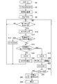
- FIG. 6 is a flowchart showing a starting process of the mounting apparatus 10, an inclination adjustment process of the optical axis AX, and a drift correction process.
- the counter C1 is a counter for counting the continuation of (light intensity ⁇ , sensor output value ⁇ (first detection state)) described later, and the counter C2 is described later (light intensity ⁇ , sensor output value ⁇ (second output) It is a counter that counts the continuation of the detection state)).
- initialization processing for reading the light intensity threshold value PL1 and the inclination threshold value RL from a nonvolatile memory is performed (S4).
- a timer for measuring the monitoring timing is started, and optical wireless communication between the optical communication apparatuses 1 and 3 is started (S6).
- the predetermined period has elapsed and the monitoring timing is reached (S8: YES)
- the light intensity (P) and the sensor output value (R) are monitored (S10).
- step S16 When the control unit 1B detects that the light intensity (P) is larger than the light intensity threshold value PL1 and the sensor output value (R) is smaller than the inclination threshold value RL (light intensity ⁇ , sensor output) (Value o) (S12: YES), the counter C1 is reset (S14), and the process returns to step S8. If it is not the light intensity ⁇ or the sensor output value ⁇ (S12: NO), the process proceeds to step S16.
- the counter C2 is reset (S18).
- communication light having sufficient light intensity is input / output to / from the light emitting / receiving surface of the light emitting / receiving element 1A (S20).
- the count value of the counter C3 is incremented by 1 (S22), and then it is determined whether or not the count value of the counter C3 is equal to or greater than a predetermined value C3X (S24).
- the count of the counter C3 detects (light intensity ⁇ , sensor output value ⁇ (third detection state)) (S16: YES)
- the actuator 7 is driven (S20), and the third detection state is It is a value that defines the timeout for resolving.
- the driving of the actuator 7 is performed at every monitoring timing, and it is defined that the driving of the actuator 7 in step S20 is continuously performed a predetermined number of times C3X.
- the number of continuous corrections is counted by counting the predetermined value C3X by the counter C3, and a timeout is set.
- the process returns to step S8.
- the counter C3 is reset in step S14.
- the counter C3 is reset in step S30.
- the counter C3 is reset.
- the value of the counter C3 reaches the predetermined value C3X (S24: YES)
- the predetermined value C3X which is the specified number of times
- the light intensity ⁇ , the sensor output value ⁇ This indicates that the (third detection state) is not resolved.
- failure of the light emitting / receiving element 1A, the tilt sensor 5, and the actuator 7 can be considered.
- the laser that is the light source of communication light is stopped, and an error signal indicating that the light intensity ⁇ , the sensor output value ⁇ (third detection state) is not resolved is output to the outside ( S26), the optical wireless communication between the optical communication devices 1 and 3 is terminated (S28).
- step S32 If neither the light intensity ⁇ , the sensor output value ⁇ , or the light intensity ⁇ , the sensor output value ⁇ (third detection state) (S12: NO, S16: NO), the process proceeds to step S32 to perform temperature drift correction processing. (S32).
- FIG. 7 is a flowchart of the subroutine of step S32.
- the control unit 1B detects that the light intensity (P) is greater than the light intensity threshold value PL1, and detects that the sensor output value (R) is equal to or greater than the inclination threshold value RL (light intensity ⁇ , sensor output value ⁇ (First detection state) (S102: YES), drift correction in step S104 is performed.
- the drift correction in step S104 is completed, the count value of the counter C1 is incremented by one (S108), and then it is determined whether or not the count value of the counter C1 is equal to or greater than a predetermined value C1X (S112).
- the count of the counter C1 detects (light intensity ⁇ , sensor output value ⁇ (first detection state)) (S102: YES)
- drift correction is performed (S104), and the first detection state is canceled. It is a value that defines the timeout for This correction operation is performed at every monitoring timing, and it is defined that the drift correction in step S104 is continuously performed a predetermined number of times C1X. The number of continuous corrections is counted by counting the predetermined value C1X by the counter C1, and a timeout is set.
- step S32 in FIG. 7 When the count value of the counter C1 is smaller than the predetermined value C1X (S112: NO), the subroutine of step S32 in FIG. 7 is terminated (S120), and the process returns to step S8. If the light intensity ⁇ and the sensor output value ⁇ are detected by subsequent monitoring (S10) (S12: YES), the counter C1 is reset in step S14. When the first detection state is canceled, the counter C1 is reset.
- the value of the counter C1 reaches the predetermined value C1X (S112: YES)
- the drift correction in step S104 is repeated a predetermined number of times C1X, which is the specified number of times, the light intensity ⁇ , the sensor output value ⁇ (first Indicates that the detection state is not resolved.
- the drift correction (S104) is performed continuously for the specified number of times, the sensor output value (R) of the tilt sensor 5 does not show a normal value, and there is a lack of drift correction, failure of the light emitting / receiving element 1A or the tilt sensor 5, etc. Conceivable.
- step S116 the optical wireless communication between the optical communication apparatuses 1 and 3 is terminated (S118).
- step S102 when it is detected that the light intensity (P) is less than or equal to the light intensity threshold value PL1 and the sensor output value (R) is smaller than the inclination threshold value RL (light intensity x, sensor output value). (Second detection state)) (S102: NO), drift correction in step S106 is performed. When the drift correction in step S106 is completed, the count value of the counter C2 is incremented by one (S110), and then it is determined whether or not the count value of the counter C2 is equal to or greater than a predetermined value C2X (S114).
- step S106 when the count of the counter C2 detects (light intensity ⁇ , sensor output value ⁇ (second detection state)) (S102: NO), drift correction is performed (S106), and the second detection state is canceled. It is a value that defines the timeout for This correction operation is performed at every monitoring timing, and it is defined that the drift correction in step S106 is continuously performed a predetermined number of times C2X. The number of continuous corrections is counted by counting the predetermined value C2X by the counter C2, and a timeout is set.
- step S32 in FIG. 7 When the count value of the counter C2 is smaller than the predetermined value C2X (S114: NO), the subroutine of step S32 in FIG. 7 is terminated (S120), and the process returns to step S8.
- the subsequent monitoring (S10) detects light intensity ⁇ , sensor output value ⁇ (third detection state) (S16: YES), the counter C2 is reset in step S18.
- the second detection state is canceled, the counter C2 is reset.
- the value of the counter C2 reaches the predetermined value C2X (S114: YES)
- the drift correction in step S106 is repeated a predetermined number of times C2X, which is the specified number of times, the light intensity ⁇ , the sensor output value ⁇ (second Indicates that the detection state is not resolved.
- the drift correction (S106) is performed continuously for the specified number of times, the sensor output value (R) of the tilt sensor 5 does not indicate a normal value, and the communication light output from the optical communication device 3 is blocked, Inadequate drift correction, failure of the light emitting / receiving element 1A, the tilt sensor 5, etc. are conceivable.
- step S116 the optical wireless communication between the optical communication apparatuses 1 and 3 is terminated (S118).
- the light intensity (P) is detected by the light emitting / receiving element 1A, and the sensor output value (R) is detected by the tilt sensor 5.
- the control unit 1B detects that the light intensity (P) is greater than the light intensity threshold value PL1 and detects that the sensor output value (R) is equal to or greater than the inclination threshold value RL in step S102. If it is (light intensity ⁇ , sensor output value ⁇ (first detection state)), the light intensity ⁇ , the inclination ( ⁇ ) of the optical axis AX is adjusted to a normal angle range.
- the sensor output value ⁇ which is the output value of the tilt sensor 5
- the sensor output value (R) which is the output value of the tilt sensor 5
- This shift is considered to be caused by temperature drift, and drift correction is performed (S104).
- drift correction is performed (S104).
- the control unit 1B detects that the light intensity (P) is equal to or less than the light intensity threshold value PL1 at every monitoring timing in step S8, and the sensor output value (R) is less than the inclination. If it is detected that the value is smaller than the value RL (light intensity ⁇ , sensor output value ⁇ (second detection state)), the inclination ( ⁇ ) of the optical axis AX may be out of the normal angle range from the light intensity ⁇ . Detected.
- the sensor output value is ⁇
- the sensor output value (R) which is the output value of the tilt sensor 5
- fluctuates due to temperature drift and is normally within the normal range even though it is out of the normal tilt range.
- a sensor output value (R) indicating that it is within is output. In this case, fluctuation due to temperature drift of the tilt sensor 5 can be eliminated by performing drift correction.
- the control unit 1B counts the value of the counter C1 to the predetermined value C1X (S112), thereby correcting drift from the light intensity ⁇ , the sensor output value ⁇ (first detection state). Timeout in Further, by counting the value of the counter C2 to the predetermined value C2X (S114), it is possible to set a timeout in drift correction from the light intensity ⁇ and the sensor output value ⁇ (second detection state).
- the average value of the sensor output value (R) is calculated, so that the inclination of the optical axis AX in the quasi-stationary state in the operating state. ( ⁇ ) can be derived.
- the drift correction is performed by adjusting the average value of the sensor output value (R) including the temperature drift to the inclination reference value R0 that is the reference value of the sensor output value.
- the optical communication device 1 when the light intensity (P) is detected to be not more than the light intensity threshold value PL1 and the sensor output value (R) is detected to be not less than the inclination threshold value RL in step S16. (Light intensity ⁇ , sensor output value ⁇ (third detection state)), the actuator 7 is driven (S20), and the light intensity (P) of the communication light is adjusted by adjusting the inclination ( ⁇ ) of the optical axis AX.
- the optical wireless can be maintained by adjusting to a state (light intensity ⁇ ) larger than the predetermined light intensity.
- this invention is not limited to the said embodiment, It is possible to implement in the various aspect which gave various change and improvement based on the knowledge of those skilled in the art.
- the inclination sensor 5 has been described on the assumption that the inclination of the posture is output as a sensor output value (R). It can also be used.
- the angular velocity detected by the angular velocity sensor is input to the control unit 1B. It is only necessary that the angular velocity is integrated by the control unit 1B so that the sensor output value (R) is detected. Further, the number of monitoring samplings for obtaining the average value of the sensor output values (R) is, for example, 4096 times.
- the sensor output value (R) By averaging the sensor output value (R) obtained by sampling 4096 times, it is possible to obtain the sensor output value (R) in a pseudo stationary state in the operating state. Note that the number of samplings is not limited to 4096. What is necessary is just to average the sensor output value (R) by sampling the number of times that the sensor output value (R) can be assumed to swing equally in the + Z direction and the ⁇ Z direction.
- the gyro sensor provided in the tilt sensor 5 may not be able to detect an accurate angular velocity during sudden acceleration / stop due to its nature. Therefore, when the magnitude of the change amount of the sensor output value (R) exceeds a predetermined value, the sensor output value (R) may be excluded from the calculation of averaging.
- produces in an average value can be reduced.
- an angular velocity sensor such as a gyro sensor
- the threshold value of the sensor output value may be set for sensor output values of a plurality of axes instead of one axis in the Z direction.
- a threshold value of the sensor output value for the three axis directions of the X, Y, and Z axes may be provided. Further, the case where only the threshold value in the + Z direction is provided as the inclination threshold value RL with respect to the Z direction has been described, but the present application is not limited to this, and a threshold value is provided in each direction of the ⁇ Z direction, Each value may be a different value.
- the drift correction method described in the embodiment can correct the tilt sensor 5 not only when temperature drift occurs but also when fluctuations occur due to other factors such as time drift. Further, the driving of the actuator 7 in step S20 (FIG.
- step S104 may be performed after it is determined that the value of the counter C1 is less than the predetermined value C1X (S112: NO).
- the drift correction in step S106 may be performed after it is determined that the value of the counter C2 is less than the predetermined value C2X (S114: NO).
- the present invention can be applied to an apparatus that includes a tilt sensor and uses sensor output values for motion control, posture control, and direction control in addition to the aspects of the optical communication device and the electronic component mounting device. These tilt sensors are used, for example, for detecting vibrations of a transported object carried by a crane, detecting postures of vehicles, ships, aircraft, robots, and the like.
- the light emitting / receiving element 1A is an example of a light receiving unit
- the control unit 1B is an example of a light intensity decrease detecting unit and an optical axis inclination detecting unit
- steps S104 and S106 are drift correcting units. It is an example.
- Optical communication device 1A Light emitting / receiving element 1B: Control unit 5: Tilt sensor 7: Actuator 9: Active mass damper AX: Optical axis
Landscapes
- Engineering & Computer Science (AREA)
- Physics & Mathematics (AREA)
- General Physics & Mathematics (AREA)
- Manufacturing & Machinery (AREA)
- Radar, Positioning & Navigation (AREA)
- Remote Sensing (AREA)
- Microelectronics & Electronic Packaging (AREA)
- Operations Research (AREA)
- Automation & Control Theory (AREA)
- Electromagnetism (AREA)
- Computer Networks & Wireless Communication (AREA)
- Signal Processing (AREA)
- Optical Communication System (AREA)
- Supply And Installment Of Electrical Components (AREA)
Abstract
傾きセンサの特性に温度ドリフトにより変動が生じた場合においても、温度ドリフトによる変動を補正して正確なセンサ傾き値を検出することで、光無線通信における通信光の光軸を調整することが可能な光通信装置、電子部品装着装置を提供することを目的とする。光通信装置(1)は、受発光素子(1A)、制御部(1B)を備える。光通信装置と傾きセンサ(5)とは、共にX軸スライダ(54)に備えられる。光強度(P)は、受発光素子によって検出される。センサ傾き値(R)は、傾きセンサによって検出される。制御部は、モニタリングタイミングで、光強度(P)が光強度しきい値PL1より高いと検出され、センサ傾き値(R)が傾きしきい値RL以上であること(光強度○、センサ傾き値×(第1検出状態))を検出し、ドリフト補正を行うことで傾きセンサの温度ドリフトによる変動を解消することができる。
Description
本発明は、光通信装置、および電子部品装着装置に関するものであり、特に光通信装置に備えられる傾きセンサのドリフト補正に関するものである。
従来より、光空間伝送装置においては、ホルダの回動軸の一端に角度センサが固定され、これによりハーフミラーの傾きを検出し得るようになされ、残りの一端にアクチュエータが固定され、当該アクチュエータを駆動してハーフミラーの傾きを可変し得るようになされている。アクチュエータにおいては、角度センサを内蔵するようになされ、位置検出素子の出力信号だけでなく、角度センサの検出結果を基準にして位置制御し得るようになされ、照射位置を補正し得る技術が開示されている(特許文献1など)。
ところで、光通信装置は、移動装置と制御装置間の信号伝送を光信号による無線伝送で行う装置であり、一方は、スライド機構等の移動装置に移動可能に備えられ、他方は制御装置に備え付けられる。通信光の光軸を一致させるため、移動装置側の光通信装置には、傾きを調整するアクチュエータが備えられる。さらに、アクチュエータを制御するために、光通信装置の傾きを検出する傾きセンサが備えられる。この傾きセンサは、傾きを示すセンサ傾き値を、傾きが0度のときの値を傾き基準値として出力する。光軸が一致している状態を傾きが0度とし、このときのセンサ傾き値の出力が傾き基準値となるように設定すれば、通信光が光軸から外れた場合においても、センサ傾き値に応じてアクチュエータを駆動することで、再度光軸を一致させることができる。しかしながら、この傾き基準値は、温度ドリフトや、その他の要因により変動が生じる。例えば、傾きセンサの温度の違いによって傾きセンサの特性が変動する場合、正確なセンサ傾き値が得られない問題がある。
これに対し、上記特許文献1に記載の背景技術は、角度センサの検出結果を基準にして角度を制御し得る技術が開示されているに過ぎない。つまり、上記特許文献1に記載の背景技術は、光通信装置に備えられる傾きセンサにかかる傾き基準値の温度ドリフトに関しては何ら記載がない。よって、上記特許文献1に記載の背景技術では、温度ドリフトの補正に関しては何ら記載がなく、傾き基準値が温度ドリフトにより変動した場合に、変動後、正確なセンサ傾き値が得ることができないという課題がある。
本発明は、このような実情に鑑みてなされたものであり、傾きセンサの特性に温度ドリフトにより変動が生じた場合においても、温度ドリフトによる変動を補正して正確なセンサ傾き値を検出することで、光無線通信における通信光の光軸を調整することが可能な光通信装置、および電子部品装着装置を提供することを目的とする。
上記課題を鑑みてなされた本願の請求項1に記載の光通信装置、および請求項6に記載の電子部品装着装置は、受光部、傾きセンサ、光強度低下検出手段、光軸傾き検出手段、およびドリフト補正手段を備える。受光部は、通信光を受光し、通信光の光強度を検出する。傾きセンサは、受光部により受光される通信光の光軸の傾きを検出する。光強度低下検出手段は、受光部により検出される光強度が所定光強度以下に低下したことを検出する。光軸傾き検出手段は、傾きセンサにより検出される光軸の傾きが所定角度以上に傾いたことを検出する。ドリフト補正手段は、光強度低下検出手段により光強度が所定光強度以下と検出されず、光軸傾き検出手段により光軸の傾きが所定角度以上と検出される場合に(第1検出状態)、傾きセンサに対してドリフト補正を行う。
また、請求項2に記載の光通信装置は、請求項1に記載の光通信装置において、光強度低下検出手段により光強度が所定光強度以下と検出され、光軸傾き検出手段により光軸の傾きが所定角度以上と検出される場合に(第2検出状態)、傾きセンサに対してドリフト補正を行う。
また、請求項3に記載の光通信装置は、請求項2に記載の光通信装置において、ドリフト補正手段がドリフト補正を所定時間継続して行った後においても、第1検出状態、もしくは第2検出状態が継続する場合に、通信光の発光を停止する。
また、請求項4に記載の光通信装置は、請求項1から3の何れか1項に記載の光通信装置において、ドリフト補正手段は、所定期間ごとにサンプリングされた光軸の傾きの平均値を算出し、算出された平均値と傾き基準値との差異を温度ドリフトによる変動値としてドリフト補正を行う。
また、本願の請求項5に記載の光通信装置は、請求項1から4の何れか1項に記載の光通信装置において、光軸の傾きを調整するアクチュエータを備える。光強度低下検出手段により光強度が所定光強度以下と検出され、光軸傾き検出手段により光軸の傾きが所定角度以上と検出される場合に(第3検出状態)、アクチュエータを駆動する。
請求項1に記載の光通信装置、および請求項6に記載の電子部品装着装置では、受光部により受光される通信光の光強度が所定光強度より大きいが通信光の光軸の傾きが所定角度以上の場合(第1検出状態)に、ドリフト補正を傾きセンサに対して行う。光強度が所定光強度より大きいならば通信光の光軸は正常な角度範囲に調整されていることとなる。光軸の角度が正常な角度範囲にあるにも拘らず光軸の傾きが所定角度以上であると検出される場合(第1検出状態)とは、傾きセンサの出力値が温度ドリフトにより変動していることを示している。第1検出状態を検出した場合に、ドリフト補正手段により温度ドリフトの補正を行うことにより傾きセンサの温度ドリフトによる変動を解消することができる。
請求項2に記載の光通信装置では、受光部により受光される通信光の光強度が所定光強度以下と検出され、通信光の光軸の傾きが所定角度より小さい場合に(第2検出状態)、ドリフト補正を傾きセンサに対して行う。光強度が所定光強度以下ならば通信光の光軸は正常な角度範囲から外れていることとなる。光軸の角度が正常な角度範囲から外れているにも拘らず光軸の傾きが所定角度より小さいと検出される場合(第2検出状態)とは、傾きセンサの出力値が温度ドリフトにより変動していることを示している。第2検出状態を検出した場合に、ドリフト補正手段により温度ドリフトの補正を行うことにより傾きセンサの温度ドリフトによる変動を解消することができる。
請求項3に記載の光通信装置では、傾きセンサに対する温度ドリフト補正にも拘わらず、異常な状態である第1、第2検出状態が解消されない状態である。この場合、装置に何らかの異常が発生したものと判断して通信光の発光を停止する。これにより、異常な状態での装置の稼働を防止することができる。
請求項4に記載の光通信装置では、所定期間ごとにサンプリングされた光軸の傾きの平均値を算出する。稼働状態において装置が静止状態での位置を中心として振動する場合に、平均値は静止状態での光軸の傾きを示す。傾き基準値とは、温度ドリフトがない状態での装置の静止状態での光軸の傾きを示す。したがって、算出された平均値の傾き基準値からの差異が温度ドリフトによる変動値であるとすることができ、これに基づいてドリフト補正を行うことができる。稼働時において装置が振動する状態においても、温度ドリフトによる変動がない状態に合わせることができる。
請求項5に記載の光通信装置では、第3検出状態を検出した場合には、光軸の傾きにより光強度が確保できないと判断されるので、アクチュエータを駆動して光軸の傾きを調整することで、通信光の光強度を所定光強度以上に調整し光無線を維持することができる。
以下、本発明の実施形態について図を参照して説明する。初めに、本願の光通信装置を適用する装置の一例として電子部品装着装置(以下、「装着装置」とする場合がある)について説明する。
(装着装置10の構成)
図1に示すように、装着装置10は、装置本体11と、装置本体11に一体的に設けられる一対の表示装置13と、装置本体11に対して着脱可能に設けられる供給装置15、16とを備える。本実施形態の装着装置10は、図3に示す制御装置80の制御に基づいて、装置本体11内に収容される搬送装置21にて搬送される回路基板100に対して電子部品(図示略)の装着作業を実施する装置である。なお、本実施形態では、図1に示すように、搬送装置21により回路基板100が搬送される方向(図2における左右方向)をX軸方向、回路基板100の搬送方向に水平でX軸方向に対して直角な方向をY軸方向と称し、説明する。
図1に示すように、装着装置10は、装置本体11と、装置本体11に一体的に設けられる一対の表示装置13と、装置本体11に対して着脱可能に設けられる供給装置15、16とを備える。本実施形態の装着装置10は、図3に示す制御装置80の制御に基づいて、装置本体11内に収容される搬送装置21にて搬送される回路基板100に対して電子部品(図示略)の装着作業を実施する装置である。なお、本実施形態では、図1に示すように、搬送装置21により回路基板100が搬送される方向(図2における左右方向)をX軸方向、回路基板100の搬送方向に水平でX軸方向に対して直角な方向をY軸方向と称し、説明する。
装置本体11は、X軸方向の一端側でY軸方向における両端部に表示装置13を各々備える。各表示装置13は、タッチパネル式の表示装置であり、電子部品の装着作業に関する情報を表示する。また、装置本体11は、Y軸方向の両側から挟むようにして装着される供給装置15、16を備える。供給装置15は、フィーダ型の供給装置であり、各種の電子部品がテーピング化されリールに巻回させた状態で収容されるテープフィーダ15Aを複数有している。供給装置16は、トレイ型の供給装置であり、複数の電子部品が載置された部品トレイ16A(図2参照)を複数有している。
図2は、装置本体11の上部カバー11A(図1参照)を取り除いた状態で装着装置10を上方(図1における上側)からの視点において示した概略平面図である。図2に示すように、装置本体11は、上記搬送装置21と、回路基板100に対して電子部品を装着する装着ヘッド22と、その装着ヘッド22を移動させる移動装置23とを基台20の上に備える。
搬送装置21は、基台20におけるY軸方向の略中央部に設けられており、1対のコンベアベルト31と、コンベアベルト31に保持された基板保持装置32と、基板保持装置32を移動させる電磁モータ33とを有している。基板保持装置32は回路基板100を保持する。電磁モータ33は、出力軸がコンベアベルト31に駆動連結されている。電磁モータ33は、例えば、回転角度を制御可能なサーボモータである。搬送装置21は、電磁モータ33の駆動に基づいてコンベアベルト31が周回動作を行うことで、基板保持装置32とともに回路基板100がX軸方向に移動する。
装着ヘッド22は、回路基板100と対向する下面に電子部品を吸着する吸着ノズル41を有する。吸着ノズル41は、正負圧供給装置42(図3参照)を介して負圧エア、正圧エア通路に通じており、負圧にて電子部品を吸着保持し、僅かな正圧が供給されることで保持した電子部品を離脱する。また、装着ヘッド22は、吸着ノズル41を昇降させるノズル昇降装置43(図3参照)及び吸着ノズル41をそれの軸心回りに自転させるノズル自転装置44(図3参照)を有しており、保持する電子部品の上下方向の位置及び電子部品の保持姿勢を変更する。ノズル昇降装置43は、駆動源として例えば電磁モータ43A(図3参照)を備える。また、装着ヘッド22は、保持する電子部品の上下方向の位置を検出するための位置検出センサ45(図3参照)を有している。また、装着ヘッド22には、回路基板100を撮影するためのマークカメラ47が下方を向いた状態で固定されている。なお、吸着ノズル41は、装着ヘッド22に対し着脱可能であり、電子部品のサイズ、形状等に応じて変更できる。
また、装着ヘッド22は、移動装置23によって基台20上の任意の位置に移動する。詳述すると、移動装置23は、装着ヘッド22をX軸方向に移動させるためのX軸方向スライド機構50と、装着ヘッド22をY軸方向に移動させるためのY軸方向スライド機構52とを備える。X軸方向スライド機構50は、X軸方向に移動可能に基台20上に設けられたX軸スライダ54と、駆動源として電磁モータ56とを有している。X軸スライダ54は、電磁モータ56の駆動に基づいてX軸方向の任意の位置に移動する。X軸スライダ54は、後述するアクチュエータ7と、アクティブマスダンパ9とを備える。
また、Y軸方向スライド機構52は、Y軸方向に移動可能にX軸スライダ54の側面に設けられたY軸スライダ58と、駆動源としての電磁モータ60とを有している。Y軸スライダ58は、電磁モータ60の駆動に基づいて、Y軸方向の任意の位置に移動する。そして、装着ヘッド22は、Y軸スライダ58に取り付けらており、移動装置23の駆動にともなって基台20上の任意の位置に移動する。これにより、マークカメラ47は、装着ヘッド22が移動させられることで回路基板100の任意の位置の表面が撮像可能となる。マークカメラ47により撮影された画像データは、画像処理装置71(図3参照)により処理され制御装置80に出力される。また、装着ヘッド22は、Y軸スライダ58にコネクタ48を介して取り付けられワンタッチで着脱可能であり、種類の異なる作業ヘッド、例えば、ディスペンサヘッド等に変更できる。
また、基台20は、Y軸方向の両側に設けられた各側面部に供給装置15、16が接続されている。各供給装置15、16は、供給する電子部品の不足や電子部品の種類の変更等に対応するべく、基台20に着脱可能とされている。また、基台20には、各供給装置15、16が接続される部分におけるX軸方向の略中央部にパーツカメラ73が各々設けられている。各パーツカメラ73は、上方を向いた状態で設けられており、各供給装置15、16から装着ヘッド22の吸着ノズル41に吸着保持された電子部品を撮像する。パーツカメラ73は、撮影された画像データを画像処理装置71(図3参照)に出力する。画像処理装置71は、処理したデータを制御装置80に出力する。
(装着装置10に適用される光通信装置1、3)
ここで、図3に示すように、本実施形態の装着装置10は、装着装置10の制御装置80と制御装置80以外の部分(各種装置)との間のデータ通信に光無線の多重化通信を用いる。なお、図3に示す装着装置10の構成は、光通信装置1、3を適用する場合の一例であり、装着装置10が備える装置の種類や数等に応じて適宜変更する。また、本願の光通信装置1、3は、装着装置10に例示される電子部品装着装置の他に、様々な製造ラインにおいて稼働する自動機などに適用可能なシステムである。
ここで、図3に示すように、本実施形態の装着装置10は、装着装置10の制御装置80と制御装置80以外の部分(各種装置)との間のデータ通信に光無線の多重化通信を用いる。なお、図3に示す装着装置10の構成は、光通信装置1、3を適用する場合の一例であり、装着装置10が備える装置の種類や数等に応じて適宜変更する。また、本願の光通信装置1、3は、装着装置10に例示される電子部品装着装置の他に、様々な製造ラインにおいて稼働する自動機などに適用可能なシステムである。
図3に示すように、制御装置80は、CPU、ROM、RAM等を備えたコンピュータを主体とするコントローラ82と、画像ボード84と、駆動制御ボード85と、I/Oボード86とを備える。コントローラ82は、各ボード84、85、86を介して各種装置と通信を行う。各ボード84、85、86は、光通信装置3を介して伝送路2の一端に接続され、その伝送路2の他端には光通信装置1を介して各種装置(カメラ、モータ、センサ等)が接続されている。各ボード84、85、86と各種装置とが入出力するデータは、光通信装置1、3を介して伝送路2において光無線による通信で伝送される。例えば、図2に示すように、移動装置23には、制御装置80に接続される光通信装置3に対向して、光通信装置1が設けられている。これにより、光通信装置1、3間で各種通信が可能とされている。
図3に示す画像ボード84は、画像データの入出力を制御するボードである。例えば、コントローラ82は、画像ボード84を介して画像処理装置71がマークカメラ47の画像データに対する処理から検出した回路基板100に関する情報(種類・形状等)や回路基板100の基板保持装置32による保持位置の誤差等の情報を受信する。駆動制御ボード85は、電磁モータに対する動作指令や電磁モータからリアルタイムでフィードバックされる情報等の入出力を制御するボードである。例えば、コントローラ82は、駆動制御ボード85を介して電磁モータ43Aにより取得されるトルク情報や位置情報(吸着ノズル41に保持される電子部品の上下位置)などのサーボ制御情報を受信する。I/Oボード86は、例えば位置検出センサ45の出力信号等の入出力を制御するボードである。これら制御装置80に各装置から入力されるデータは、光通信装置1により多重化された上で光無線信号として伝送路2を伝送される。光通信装置3は、伝送された多重化信号の多重化を解除し個々のデータに分離する処理を行う。光通信装置3は、分離されたデータのうち、画像データを画像ボード84に、サーボ制御情報を駆動制御ボード85に、I/O信号をI/Oボード86に転送する。
一方で、コントローラ82は、光通信装置3により受信された各データを処理する。コントローラ82は、例えば処理結果に基づいた電磁モータ43Aに対する制御信号を、駆動制御ボード85を介して光通信装置3に出力する。光通信装置1は、光通信装置3から伝送される制御信号をノズル昇降装置43に転送する。これにより、電磁モータ43Aが制御信号に基づいて動作する。また、コントローラ82は、例えば表示装置13の表示を変更する制御信号をI/Oボード86、光通信装置3、光通信装置1を介して表示装置13に出力する。このように、制御装置80と制御装置80以外の各装置とで送受信される各種情報は、伝送路2上を多重化されたデータ、例えば時分割多重(TDM)方式のフレームデータとして送受信される。なお、制御装置80と他の装置間の通信は、その一部だけを光無線通信にて実施してよい。
上述した装着装置10では、基板保持装置32に保持された回路基板100に対して装着ヘッド22によって電子部品の装着作業を行う。具体的には、コントローラ82は、搬送装置21を駆動して回路基板100を作業位置まで搬送し、電磁モータ33を停止させて回路基板100を固定的に保持させる。次に、コントローラ82は、移動装置23を駆動して装着ヘッド22を回路基板100上に移動させマークカメラ47により回路基板100を撮像する。この際に、コントローラ82は、画像処理装置71から受信した回路基板の種類及び回路基板100の保持位置の誤差を判定する。次に、コントローラ82は、基板の種類に対する判定結果に応じた電子部品を有する供給装置15、16を駆動し、該当する電子部品を装着ヘッド22への供給位置に送り出す制御を行う。次に、コントローラ82は、移動装置23を駆動して供給位置の搬送された電子部品を装着ヘッド22の吸着ノズル41により吸着保持させる。
次に、コントローラ82は、電子部品を保持した装着ヘッド22をパーツカメラ73上に移動させて電子部品の状態を撮像させる。この際に、コントローラ82は、撮像結果に基づいて電子部品の保持位置の誤差を取得する。次に、コントローラ82は、装着ヘッド22を回路基板100上の装着位置に移動させ回路基板及び電子部品の保持位置誤差に基づいて吸着ノズル41を自転させた後に電子部品を回路基板100に装着させる。
図4は、X軸スライダ54を図2の-Y方向から見た光通信装置1を模式的に示す図である。図4においてZ方向は装置の上下方向である。X軸スライダ54の上部には、光通信装置1、傾きセンサ5、アクチュエータ7、アクティブマスダンパ9が備えられる。光通信装置1は、X軸スライダ54に備えられているため、稼働状態において、X軸スライダ54の移動による、光通信装置3との間の光軸AXのずれや光通信装置1の振動が生ずる恐れがある。よって、このような場合においても、光通信装置1と光通信装置3とを結ぶ光軸AXが、光通信装置1の受発光部1Aで受発光される通信光が通信に十分な光強度を確保できるような傾きに保持されるように、傾きセンサ5、アクチュエータ7、およびアクティブマスダンパ9が用いられる。
また、光通信装置1には、受発光素子1A、制御部1Bが備えられる。受発光素子1Aは、通信光の受光を行うフォトダイオード等の受光素子、および通信光の発光を行うレーザダイオード等の発光素子を備える。受発光される通信光の光強度が、確実な通信が可能である十分な強度となるように、光軸AXの傾きが調整される。受光素子であるフォトダイオードは、通信光の光強度(P)(図5)に応じた電流量の電流を流す。制御部1Bは、流れる電流の電流量から入射される通信光の光強度(P)を検出する。流れる電流の温度によるばらつきは、後述する傾きセンサ5の出力のばらつきと比べ、十分に小さいものである。制御部1Bは、受発光素子1A、および傾きセンサ5から入力される信号を処理し、処理結果に基づいてアクチュエータ7、およびアクティブマスダンパ9の制御を行う。また、制御部1Bは、フラッシュメモリ等の不揮発性メモリ(不図示)を備え、後述する光強度(P)のしきい値である光強度しきい値PL1(図5)、および後述するセンサ出力値(R)(図5)のしきい値である傾きしきい値RL(図5)を記憶する。
傾きセンサ5は、X軸スライダ54のZ方向の振動による変位を検出するものである。傾きセンサ5は、図示しないジャイロセンサを備える。ジャイロセンサは角速度を検出する。傾きセンサ5では、ジャイロセンサからの出力である角速度を示す電圧値を時間積分することでセンサ出力値(R)を検出する。ジャイロセンサは、X、Y、Zの3方向の角速度を検出することもでき、この場合には制御部1Bは、各方向に対する振動による変位を検出する。センサ出力値(R)は、図5において後述するように温度ドリフトを有している(センサ出力値特性線RA、RB、RC)。
アクチュエータ7は、制御部1Bの制御により、光通信装置1の姿勢を調整することで光軸AXの傾きを調整して、受発光素子1Aの受発光面に十分な光強度の通信光が入出力されるように駆動される。アクティブマスダンパ9は、制御部1Bの制御により、X軸スライダ54に発生する振動を緩和する。
図5は、光強度(P)と光軸AXの傾き(θ)、およびZ方向のずれを示すセンサ出力値(R)と光軸AXの傾き(θ)の相関関係を併せて示すグラフである。以下の説明では、前者を光強度特性線PW、後者をセンサ出力値特性線RA、RB、RCとして説明する。ここで、X軸は光軸AXの傾き(θ)であり、図4に示すZ方向への変位に応じて生ずる傾きである。
Y1軸は、受発光素子1Aに受光される通信光の光強度(P)を示す。光強度特性線PWは、光軸AXの傾き(θ)が増加するほど、光強度(P)は低減する相関関係を示す。光強度値P0は、光強度(P)が最も高い値である。光軸AXの傾き(θ)がゼロのときの光強度値を示す。光強度(P)が光強度しきい値PL1より高いときには、正常な光強度(P)により光無線が行われる。光強度しきい値PL2は、光無線において、所定の通信品質を満たす最低限の光強度(P)である。
Y2軸は、傾きセンサ5が検出するセンサ出力値(R)を示す。センサ出力値特性線RAは温度ドリフトを含まない場合であり、センサ出力値特性線RB、RCは温度ドリフトを含む場合である。センサ出力値特性線RBは正の温度ドリフトを含み、センサ出力値特性線RCは負の温度ドリフトを含む。傾き基準値R0は、温度ドリフトがない状態での光通信装置1の静止状態における、光軸AXの傾き(θ)であり、制御部1Bに記憶されるセンサ出力値の基準値である。傾き基準値RA0、RB0、RC0は、実際の光軸AXの傾き(θ)がゼロの場合に、各々のセンサ出力値特性線RA、RB、RCにおいて傾きセンサ5が出力するセンサ出力値を示す。温度ドリフトがないセンサ出力値特性線RAでは、傾き基準値RA0が傾き基準値R0に一致する。正の温度ドリフトを有するセンサ出力値特性線RBでは、傾き基準値RB0は傾き基準値R0より大きな傾きを有して出力され、負の温度ドリフトを有するセンサ出力値特性線RCでは、傾き基準値RC0は傾き基準値R0より小さな傾きを有して出力される。センサ出力値(R)が傾きしきい値RL以下の場合に、温度ドリフトがない条件で、光通信装置1の受発光部1Aで受発光される通信光の光強度が光無線に必要な正常な強度の範囲内にある傾きであるとされる。
先ず、傾きセンサ5に温度ドリフトがない場合について説明する。この場合、傾きセンサ5はセンサ出力値特性線RAの特性を示す。光強度特性線PWと光強度しきい値PL1との交点X1、およびセンサ出力値特性線RAと傾きしきい値RLとの交点X2における光軸AXの傾き(θ)は、傾きθ0で一致する。センサ出力値特性線RAが温度ドリフトがない特性線であるので、実際の傾きしきい値RLにおいて光強度しきい値PL1が一致するからである。
光軸AXの傾き(θ)がゼロから傾きθ0までの領域では、光強度特性線PWが光強度しきい値PL1より大きい範囲にあり光無線には十分な光強度が確保される(光強度○)。またセンサ出力値特性線RAが傾きしきい値RLより小さい範囲にあり傾きセンサ5から出力されるセンサ出力値(R)は許容範囲内にあると検出される(センサ出力値○)。光強度○、センサ出力値○を検出する場合は、正常な光強度、センサ出力値により光無線が行われる。
光軸AXの傾きが、傾きθ0を越える領域では、光強度特性線PWが光強度しきい値PL1以下と検出され(光強度×)、かつセンサ出力値特性線RAが傾きしきい値RL以上と検出される(センサ出力値×)。制御部1Bは、光強度×およびセンサ出力値×(第3検出状態)を検出すると、アクチュエータ7を駆動して、光軸AXの傾き(θ)を調整することで、受発光素子1Aの受発光面に十分な光強度の通信光が入出力されるようにする。
次に、傾きセンサ5に正の温度ドリフトがある場合について説明する。この場合、傾きセンサ5はセンサ出力値特性線RBの特性を示す。センサ出力値特性線RBと傾きしきい値RLとの交点X3における光軸AXの傾き(θ)は、傾きθ1である。光強度特性線PWと光強度しきい値PL1との交点X1における光軸AXの傾き(θ)と不一致となる。傾きセンサ5における正の温度ドリフトにより、交点X3での光軸AXの傾き(θ=θ1)は、交点X1での光軸AXの傾き(θ=θ0)より小さな傾きとなる(θ1<θ0)。
光軸AXの傾き(θ)がゼロから傾きθ1までの領域では、光強度特性線PWが光強度しきい値PL1より大きい範囲にあり光無線には十分な光強度が確保される(光強度○)。またセンサ出力値特性線RBが傾きしきい値RLより小さい範囲にあり傾きセンサ5から出力されるセンサ出力値(R)は許容範囲内にあると検出される(センサ出力値○)。光強度○、センサ出力値○を検出する場合であり、正常な光強度、センサ出力値により光無線が行われる。
光軸AXの傾き(θ)が傾きθ1からθ0までの領域では、光強度特性線PWが光強度しきい値PL1より大きい範囲にあり光無線には十分な光強度が確保される(光強度○)。一方、センサ出力値RBが傾きしきい値RL以上と検出される(センサ出力値×)。よって、制御部1Bは、光強度○およびセンサ出力値×(第1検出状態)を検出すると、傾きセンサ5に温度ドリフトがあるとして後述するドリフト補正を行う。
光軸AXの傾き(θ)が傾きθ0を越える領域では、光強度特性線PWが光強度しきい値PL1以下と検出され(光強度×)、かつセンサ出力値特性線RAが傾きしきい値RL以上と検出される(センサ出力値×)。制御部1Bは、光強度×およびセンサ出力値×(第3検出状態)を検出すると、アクチュエータ7を駆動して、光軸AXの傾き(θ)を調整することで、受発光素子1Aの受発光面に十分な光強度の通信光が入出力されるようにする。
次に、傾きセンサ5に負の温度ドリフトがある場合について説明する。この場合、傾きセンサ5はセンサ出力値特性線RCの特性を示す。センサ出力値特性線RCと傾きしきい値RLとの交点X4における光軸AXの傾き(θ)は、傾きθ2である。光強度特性線PWと光強度しきい値PL1との交点X1における光軸AXの傾き(θ)と不一致となる。傾きセンサ5における負の温度ドリフトにより、交点X4での光軸AXの傾き(θ=θ2)は、交点X1での光軸AXの傾き(θ=θ0)より大きな傾きとなる(θ2>θ0)。
光軸AXの傾き(θ)がゼロから傾きθ0までの領域では、光強度特性線PWが光強度しきい値PL1より大きい範囲にあり光無線には十分な光強度が確保される(光強度○)。またセンサ出力値特性線RCが傾きしきい値RLより小さい範囲にあり傾きセンサ5から出力されるセンサ出力値(R)は許容範囲内にあると検出される(センサ出力値○)。光強度○、センサ出力値○を検出する場合であり、正常な光強度、センサ出力値により光無線が行われる。
光軸AXの傾き(θ)が、傾きθ0からθ2までの領域では、光強度特性線PWが光強度しきい値PL1以下と検出される(光強度×)。一方、センサ出力値RCが傾きしきい値RLより小さい範囲にあり傾きセンサ5から出力されるセンサ出力値(R)は許容範囲内にあると検出される(センサ出力値○)。よって、制御部1Bは、光強度×およびセンサ出力値○(第2検出状態)を検出すると、傾きセンサ5に温度ドリフトがあるとて後述するドリフト補正を行う。
光軸AXの傾き(θ)が傾きθ2を越える領域では、光強度特性線PWが光強度しきい値PL1以下と検出され(光強度×)、かつセンサ出力値特性線RCが傾きしきい値RL以上と検出される(センサ出力値×)。制御部1Bは、光強度×およびセンサ出力値×(第3検出状態)を検出すると、アクチュエータ7を駆動して、光軸AXの傾き(θ)を調整することで、受発光素子1Aの受発光面に十分な光強度の通信光が入出力されるようにする。
装着装置10の稼働状態において、光通信装置1が備えられるX軸スライダ54の移動により光通信装置1が±Z方向に振動し、光軸AXに±Z方向の振動が発生する。よって、稼働状態において検出されるセンサ出力値(R)は、振動による光軸AXの傾き(θ)のずれを含んだ値となる。しかしながら、装着装置10の稼働状態における振動は、十分に長い時間幅で見ると、+Z方向と-Z方向とに均等に振れていると考えられる。つまり、センサ出力値(R)を複数回数のモニタリングサンプリングにより検出し、各々のセンサ出力値(R)の平均値を算出することで、擬似的な静止状態での光軸AXの傾き(θ)を導き出すことができる。こうして得られたセンサ出力値(R)の平均値は、稼働状態における擬似的な静止状態の位置、すなわちZ軸方向の光通信装置1の振動の中心位置に略一致する。ここで、傾きセンサ5は、温度に応じて出力されるセンサ出力値(R)に温度ドリフトを含んだものとなる。したがって、算出されたセンサ出力値(R)の平均値を、センサ出力値の基準値である傾き基準値R0に調整することによりドリフト補正を行うことができる。稼働時において装置が振動する状態においても、温度ドリフトによる変動がない状態に合わせることができる。なお、傾き基準値R0は、あらかじめ、装着装置10の工場出荷時やキャリブレーション時などに計測された値であり、図示しない記憶部などに記憶されているものとする。
図6は、装着装置10の起動処理、光軸AXの傾き調整処理、ドリフト補正処理を示すフローチャートである。まず、ステップS0で、装着装置10の起動が開始され、制御部1Bは、カウンタC1、C2、C3を初期化する(C1=C2=C3=0)(S2)。ここで、カウンタC1は後述する(光強度○、センサ出力値×(第1検出状態))の継続を計数するカウンタであり、カウンタC2は後述する(光強度×、センサ出力値○(第2検出状態))の継続を計数するカウンタである。そして、光強度しきい値PL1、傾きしきい値RLを不揮発性メモリ(不図示)から読み出す初期化処理を行う(S4)。次に、モニタリングタイミングを計時するタイマを起動し、光通信装置1、3の間での光無線を開始する(S6)。所定期間経過しモニタリングタイミングに達すると(S8:YES)、光強度(P)、センサ出力値(R)をモニタリングする(S10)。
制御部1Bが、光強度(P)が光強度しきい値PL1より大きいと検出され、かつセンサ出力値(R)が傾きしきい値RLより小さいと検出されると(光強度○、センサ出力値○)(S12:YES)、カウンタC1をリセットして(S14)、ステップS8に戻る。光強度○、センサ出力値○ではない場合は(S12:NO)、ステップS16に進む。光強度(P)が光強度しきい値PL1以下と検出され、かつセンサ出力値(R)が傾きしきい値RL以上と検出されると(光強度×、センサ出力値×(第3検出状態))(S16:YES)、カウンタC2をリセットする(S18)。次に、アクチュエータ7を駆動し、光軸AXの傾き(θ)を調整することで、受発光素子1Aの受発光面に十分な光強度の通信光が入出力されるようにする(S20)。
ステップS20のアクチュエータ7の駆動が完了すると、カウンタC3のカウント値を1つ加算し(S22)、次に、カウンタC3のカウント値が所定値C3X以上か否かを判定する(S24)。ここで、カウンタC3のカウントは、(光強度×、センサ出力値×(第3検出状態))を検出した際に(S16:YES)アクチュエータ7の駆動を行い(S20)、第3検出状態が解消するためのタイムアウトを規定する値である。このアクチュエータ7の駆動はモニタリングタイミングごとに行われるところ、ステップS20のアクチュエータ7の駆動を連続して所定値C3Xの回数行うとして規定されている。カウンタC3による所定値C3Xのカウントにより連続補正回数を計数してタイムアウトとする。
カウンタC3のカウント値が所定値C3Xより小さい場合には(S24:NO)、ステップS8に戻る。その後のモニタリングにより(S10)、光強度○、センサ出力値○が検出されると(S12:YES)、ステップS14においてカウンタC3がリセットされる。又は、光強度○、センサ出力値○、および光強度×、センサ出力値×(第3検出状態)のどちらでもない場合(S12:NO、S16:NO)、ステップS30においてカウンタC3がリセットされる。第3検出状態が解消されることによりカウンタC3がリセットされる。一方、カウンタC3の値が所定値C3Xに達することにより(S24:YES)、ステップS20のアクチュエータ7の駆動が規定回数である所定値C3X回繰り返されても、光強度×、センサ出力値×(第3検出状態)が解消しないことを示す。この場合、受発光素子1Aや傾きセンサ5、アクチュエータ7の故障等が考えられる。このような場合には、通信光の発光源であるレーザーを停止し、外部に、光強度×、センサ出力値×(第3検出状態)が解消しないことを示すエラー信号を出力してから(S26)、光通信装置1、3間での光無線を終了する(S28)。
光強度○、センサ出力値○、もしくは光強度×、センサ出力値×(第3検出状態)のどちらでもない場合(S12:NO、S16:NO)、ステップS32に移り温度ドリフトの補正処理を行う(S32)。
図7は、ステップS32のサブルーチンのフローチャートである。制御部1Bが、光強度(P)が光強度しきい値PL1より大きいと検出され、センサ出力値(R)が傾きしきい値RL以上と検出されると(光強度○、センサ出力値×(第1検出状態))(S102:YES)、ステップS104のドリフト補正を行う。ステップS104のドリフト補正が完了すると、カウンタC1のカウント値を1つ加算し(S108)、次に、カウンタC1のカウント値が所定値C1X以上か否かを判定する(S112)。ここで、カウンタC1のカウントは、(光強度○、センサ出力値×(第1検出状態))を検出した際に(S102:YES)ドリフト補正を行い(S104)、第1検出状態が解消するためのタイムアウトを規定する値である。この補正動作はモニタリングタイミングごとに行われるところ、ステップS104のドリフト補正を連続して所定値C1Xの回数行うとして規定されている。カウンタC1による所定値C1Xのカウントにより連続補正回数を計数してタイムアウトとする。
カウンタC1のカウント値が所定値C1Xより小さい場合には(S112:NO)、図7のステップS32のサブルーチンを終了し(S120)、ステップS8に戻る。その後のモニタリングにより(S10)、光強度○、センサ出力値○が検出されると(S12:YES)、ステップS14においてカウンタC1がリセットされる。第1検出状態が解消されることによりカウンタC1がリセットされる。一方、カウンタC1の値が所定値C1Xに達することにより(S112:YES)、ステップS104のドリフト補正が規定回数である所定値C1X回繰り返されても、光強度○、センサ出力値×(第1検出状態)が解消しないことを示す。規定回数連続してドリフト補正(S104)を行っても、傾きセンサ5のセンサ出力値(R)が正常な値を示さず、ドリフト補正の不備、受発光素子1Aや傾きセンサ5の故障等が考えられる。このような場合には、通信光の発光源であるレーザーを停止し、外部に、光強度○、センサ出力値×(第1検出状態)が解消しないことを示すエラー信号を出力してから(S116)、光通信装置1、3間での光無線を終了する(S118)。
また、ステップS102において、光強度(P)が光強度しきい値PL1以下と検出され、センサ出力値(R)が傾きしきい値RLより小さいと検出されると(光強度×、センサ出力値○(第2検出状態))(S102:NO)、ステップS106のドリフト補正を行う。ステップS106のドリフト補正が完了すると、カウンタC2のカウント値を1つ加算し(S110)、次に、カウンタC2のカウント値が所定値C2X以上か否かを判定する(S114)。ここで、カウンタC2のカウントは、(光強度×、センサ出力値○(第2検出状態))を検出した際に(S102:NO)ドリフト補正を行い(S106)、第2検出状態が解消するためのタイムアウトを規定する値である。この補正動作はモニタリングタイミングごとに行われるところ、ステップS106のドリフト補正を連続して所定値C2Xの回数行うとして規定されている。カウンタC2による所定値C2Xのカウントにより連続補正回数を計数してタイムアウトとする。
カウンタC2のカウント値が所定値C2Xより小さい場合には(S114:NO)、図7のステップS32のサブルーチンを終了し(S120)、ステップS8に戻る。その後のモニタリングにより(S10)、光強度×、センサ出力値×(第3検出状態)が検出されると(S16:YES)、ステップS18においてカウンタC2がリセットされる。第2検出状態が解消されることによりカウンタC2がリセットされる。一方、カウンタC2の値が所定値C2Xに達することにより(S114:YES)、ステップS106のドリフト補正が規定回数である所定値C2X回繰り返されても、光強度×、センサ出力値○(第2検出状態)が解消しないことを示す。規定回数連続してドリフト補正(S106)を行っても、傾きセンサ5のセンサ出力値(R)が正常な値を示さず、光通信装置3から出力される通信光が遮断されたことや、ドリフト補正の不備、受発光素子1A、傾きセンサ5の故障等が考えられる。このような場合には、通信光の発光源であるレーザーを停止し、外部に、光強度×、センサ出力値○(第2検出状態)が解消しないことを示すエラー信号を出力してから(S116)、光通信装置1、3間での光無線を終了する(S118)。
以上、詳細に説明した通り、本実施形態の光通信装置1によれば、受発光素子1Aによって光強度(P)が検出され、傾きセンサ5によってセンサ出力値(R)が検出される。制御部1Bは、ステップS8のモニタリングタイミングごとに、ステップS102により、光強度(P)が光強度しきい値PL1より大きいと検出され、センサ出力値(R)が傾きしきい値RL以上と検出されると(光強度○、センサ出力値×(第1検出状態))、光強度○であるので、光軸AXの傾き(θ)は正常な角度範囲に調整されていることとなる。その一方、センサ出力値×であることから、傾きセンサ5の出力値であるセンサ出力値(R)が本来の光軸AXの傾き(θ)からずれた値を出力していることとなる。このずれは温度ドリフトにより生じているものと考え、ドリフト補正を行う(S104)。これにより、傾きセンサ5のセンサ出力値(R)における温度ドリフトによる変動を解消することができる。
また、光通信装置1によれば、制御部1Bは、ステップS8のモニタリングタイミングごとに、光強度(P)が光強度しきい値PL1以下と検出され、センサ出力値(R)が傾きしきい値RLより小さいと検出されると(光強度×、センサ出力値○(第2検出状態))、光強度×から、光軸AXの傾き(θ)が正常な角度範囲から外れていることが検出される。一方、センサ出力値○であることから、傾きセンサ5の出力値であるセンサ出力値(R)が温度ドリフトにより変動して、本来なら正常な傾き範囲から外れているにもかかわらず正常の範囲内にあるとのセンサ出力値(R)を出力する。この場合に、ドリフト補正を行うことで傾きセンサ5の温度ドリフトによる変動を解消することができる。
また、光通信装置1によれば、制御部1Bは、カウンタC1の値を所定値C1Xまでカウントすることで(S112)、光強度○、センサ出力値×(第1検出状態)からのドリフト補正におけるタイムアウトとすることができる。また、カウンタC2の値を所定値C2Xまでカウントすることで(S114)、光強度×、センサ出力値○(第2検出状態)からのドリフト補正におけるタイムアウトとすることができる。これらのタイムアウトまでカウンタC1、C2がカウントされることで、ドリフト補正(S104、S106)での補正動作が規定回数繰り返されてもセンサ出力値(R)のずれが解消できなければ、装置上の何らかの不具合があるものとして通信光の発光を停止し、外部に、第1検出状態、もしくは第2検出状態が解消しないことを示すエラー信号を出力してから(S116)、光通信装置1、3間での光無線を終了する(S118)。これにより、異常な状態での光無線の継続を回避することができる。
また、光通信装置1によれば、ステップS104、S106のドリフト補正において、センサ出力値(R)の平均値を算出することで、稼働状態において、擬似的に静止状態での光軸AXの傾き(θ)を導き出すことができる。温度ドリフトを含んだセンサ出力値(R)の平均値を、センサ出力値の基準値である傾き基準値R0に調整することによりドリフト補正がされる。これにより、稼働時において装置が振動する状態においても、温度ドリフトを相殺してドリフト変動がない状態に合わせることができる。
また、光通信装置1によれば、ステップS16において、光強度(P)が光強度しきい値PL1以下と検出され、かつセンサ出力値(R)が傾きしきい値RL以上と検出された時(光強度×、センサ出力値×(第3検出状態))、アクチュエータ7を駆動して(S20)、光軸AXの傾き(θ)を調整することで、通信光の光強度(P)を所定光強度より大きな状態(光強度○)に調整し、光無線を維持することができる。
なお、本発明は、上記実施形態に限定されるものではなく、当業者の知識に基づいて種々の変更、改良を施した種々の態様で実施することが可能である。
また、傾きセンサ5は、姿勢の傾きをセンサ出力値(R)を出力するとして説明したが、傾きセンサはこれに限定されるものではなく、傾きセンサ5に代えて角速度を検出する角速度センサを利用することもできる。この場合、角速度センサが検出する角速度は、制御部1Bに入力される。制御部1Bによって角速度の積分処理がされ、センサ出力値(R)が検出されるようにすれば良い。
また、センサ出力値(R)の平均値を求めるモニタリングサンプリングの回数は、例えば4096回である。4096回のサンプリングで得られたセンサ出力値(R)を平均化することにより、稼動状態において擬似的な静止状態でのセンサ出力値(R)を求めることができる。なお、サンプリングの回数は、4096回に限定されない。センサ出力値(R)が+Z方向と-Z方向とに均等に振れるみなすことができる回数のサンプリングによるセンサ出力値(R)を平均化してやればよい。
また、傾きセンサ5に備えられるジャイロセンサは、性質上、急加速・急停止のとき、正確な角速度を検出できない恐れがある。よって、センサ出力値(R)の変化量の大きさが所定値を越える場合に、このセンサ出力値(R)を平均化の算出から除外してもよい。これにより、平均値に発生する誤差を低減することができる。
また、ジャイロセンサなどの角速度センサを用いる場合において、角速度センサが検出する角速度から、急加速・急停止が発生したことを検出してもよい。この場合、角速度が所定の値を超える時点に対応するセンサ出力値(R)は、サンプリングデータから除外することが好ましい。これにより、検出される傾きの精度を向上させることができる。
また、センサ出力値のしきい値として、Z方向の1軸に代えて複数軸のセンサ出力値に対して設定しても良い。例えば、X、Y、Z軸の3軸方向に対するセンサ出力値のしきい値を設けてもよい。また、Z方向に対する傾きしきい値RLとして+Z方向のしきい値のみを備える場合について説明したが、本願はこれに限定されるものではなく、±Z方向のそれぞれの方向にしきい値を設け、またそれぞれの値が異なる値であっても構わない。
また、実施形態において説明したドリフト補正方法は、温度ドリフトだけでなく、経時ドリフトなど、その他の要因により変動が生じた場合にも、傾きセンサ5について補正することができる。
また、ステップS20(図6)のアクチュエータ7の駆動は、カウンタC3の値が所定値C3X未満と判断された後に(S24:NO)行っても構わない。この場合、カウンタC3の値が所定値C3Xに達すると(S24:YES)、次にレーザーを停止し、エラー信号を出力してから(S26)、光通信装置1、3間での光無線を終了する(S28)。これにより、アクチュエータ7の駆動を省いて、速やかに、光通信装置1、3間での光無線を終了することができる。
同様に、ステップS104(図7)のドリフト補正は、カウンタC1の値が所定値C1X未満と判断された後に(S112:NO)行っても構わない。また、ステップS106(図7)のドリフト補正は、カウンタC2の値が所定値C2X未満と判断された後に(S114:NO)行っても構わない。
また、本発明は、光通信装置、および電子部品装着装置の態様の他に、傾きセンサを備え、センサ出力値を運動制御、姿勢制御、方向制御に用いる装置に適用できる。これら傾きセンサは、例えばクレーンによって運ばれる運搬物の振れ検出や、車両、船舶、航空機、ロボット等の姿勢検出等に用いられる。
また、傾きセンサ5は、姿勢の傾きをセンサ出力値(R)を出力するとして説明したが、傾きセンサはこれに限定されるものではなく、傾きセンサ5に代えて角速度を検出する角速度センサを利用することもできる。この場合、角速度センサが検出する角速度は、制御部1Bに入力される。制御部1Bによって角速度の積分処理がされ、センサ出力値(R)が検出されるようにすれば良い。
また、センサ出力値(R)の平均値を求めるモニタリングサンプリングの回数は、例えば4096回である。4096回のサンプリングで得られたセンサ出力値(R)を平均化することにより、稼動状態において擬似的な静止状態でのセンサ出力値(R)を求めることができる。なお、サンプリングの回数は、4096回に限定されない。センサ出力値(R)が+Z方向と-Z方向とに均等に振れるみなすことができる回数のサンプリングによるセンサ出力値(R)を平均化してやればよい。
また、傾きセンサ5に備えられるジャイロセンサは、性質上、急加速・急停止のとき、正確な角速度を検出できない恐れがある。よって、センサ出力値(R)の変化量の大きさが所定値を越える場合に、このセンサ出力値(R)を平均化の算出から除外してもよい。これにより、平均値に発生する誤差を低減することができる。
また、ジャイロセンサなどの角速度センサを用いる場合において、角速度センサが検出する角速度から、急加速・急停止が発生したことを検出してもよい。この場合、角速度が所定の値を超える時点に対応するセンサ出力値(R)は、サンプリングデータから除外することが好ましい。これにより、検出される傾きの精度を向上させることができる。
また、センサ出力値のしきい値として、Z方向の1軸に代えて複数軸のセンサ出力値に対して設定しても良い。例えば、X、Y、Z軸の3軸方向に対するセンサ出力値のしきい値を設けてもよい。また、Z方向に対する傾きしきい値RLとして+Z方向のしきい値のみを備える場合について説明したが、本願はこれに限定されるものではなく、±Z方向のそれぞれの方向にしきい値を設け、またそれぞれの値が異なる値であっても構わない。
また、実施形態において説明したドリフト補正方法は、温度ドリフトだけでなく、経時ドリフトなど、その他の要因により変動が生じた場合にも、傾きセンサ5について補正することができる。
また、ステップS20(図6)のアクチュエータ7の駆動は、カウンタC3の値が所定値C3X未満と判断された後に(S24:NO)行っても構わない。この場合、カウンタC3の値が所定値C3Xに達すると(S24:YES)、次にレーザーを停止し、エラー信号を出力してから(S26)、光通信装置1、3間での光無線を終了する(S28)。これにより、アクチュエータ7の駆動を省いて、速やかに、光通信装置1、3間での光無線を終了することができる。
同様に、ステップS104(図7)のドリフト補正は、カウンタC1の値が所定値C1X未満と判断された後に(S112:NO)行っても構わない。また、ステップS106(図7)のドリフト補正は、カウンタC2の値が所定値C2X未満と判断された後に(S114:NO)行っても構わない。
また、本発明は、光通信装置、および電子部品装着装置の態様の他に、傾きセンサを備え、センサ出力値を運動制御、姿勢制御、方向制御に用いる装置に適用できる。これら傾きセンサは、例えばクレーンによって運ばれる運搬物の振れ検出や、車両、船舶、航空機、ロボット等の姿勢検出等に用いられる。
上記実施形態において、受発光素子1Aは受光部の一例であり、また、制御部1Bは光強度低下検出手段、および光軸傾き検出手段の一例であり、また、ステップS104、S106はドリフト補正手段の一例である。
1、3:光通信装置 1A:受発光素子 1B:制御部 5:傾きセンサ 7:アクチュエータ 9:アクティブマスダンパ AX:光軸
Claims (6)
- 通信光を受光し、前記通信光の光強度を検出する受光部と、
前記受光部により受光される前記通信光の光軸の傾きを検出する傾きセンサと、
前記受光部により検出される前記光強度が所定光強度以下に低下したことを検出する光強度低下検出手段と、
前記傾きセンサにより検出される前記光軸の傾きが所定角度以上に傾いたことを検出する光軸傾き検出手段と、
前記光強度低下検出手段により前記光強度が前記所定光強度以下と検出されず、前記光軸傾き検出手段により前記光軸の傾きが前記所定角度以上と検出される場合に(第1検出状態)、前記傾きセンサに対してドリフト補正を行うドリフト補正手段とを備えることを特徴とする光通信装置。 - 前記ドリフト補正手段は、
前記光強度低下検出手段により前記光強度が前記所定光強度以下と検出され、前記光軸傾き検出手段により前記光軸の傾きが所定角度以上と検出されない場合に(第2検出状態)、前記傾きセンサに対してドリフト補正を行うことを特徴とする請求項1に記載の光通信装置。 - 前記ドリフト補正手段が前記ドリフト補正を所定時間継続して行った後においても、前記第1検出状態、もしくは前記第2検出状態が継続する場合に、前記通信光の発光を停止することを特徴とする請求項2に記載の光通信装置。
- 前記ドリフト補正手段は、所定期間ごとにサンプリングされた前記光軸の傾きの平均値を算出し、算出された前記平均値と傾き基準値との差異を温度ドリフトによる変動値としてドリフト補正を行うことを特徴とする請求項1から3の何れか1項に記載の光通信装置。
- 前記光軸の傾きを調整するアクチュエータと、
前記光強度低下検出手段により前記光強度が前記所定光強度以下と検出され、前記光軸傾き検出手段により前記光軸の傾きが前記所定角度以上と検出される場合に(第3検出状態)、前記アクチュエータを駆動することを特徴とする請求項1から4の何れか1項に記載の光通信装置。 - 電子部品の基板への実装作業に係る各種のデータを通信光により伝送する電子部品装着装置であって、
前記通信光を受光し、前記通信光の光強度を検出する受光部と
前記受光部により受光される前記通信光の光軸の傾きを検出する傾きセンサと、
前記受光部により検出される前記光強度が前記所定光強度以下に低下したことを検出する光強度低下検出手段と、
前記傾きセンサにより前記光軸の傾きが所定角度以上に傾いたことを検出する光軸傾き検出手段と、
前記光強度低下検出手段により前記光強度が所定光強度以下と検出されず、前記光軸傾き検出手段により検出される前記光軸の傾きが前記所定角度以上と検出される場合に(第1検出状態)前記傾きセンサに対してドリフト補正を行うドリフト補正手段とを備えることを特徴とする電子部品装着装置。
Priority Applications (2)
| Application Number | Priority Date | Filing Date | Title |
|---|---|---|---|
| PCT/JP2012/082167 WO2014091577A1 (ja) | 2012-12-12 | 2012-12-12 | 光通信装置、および電子部品装着装置 |
| JP2014551785A JP5976841B2 (ja) | 2012-12-12 | 2012-12-12 | 光通信装置、および電子部品装着装置 |
Applications Claiming Priority (1)
| Application Number | Priority Date | Filing Date | Title |
|---|---|---|---|
| PCT/JP2012/082167 WO2014091577A1 (ja) | 2012-12-12 | 2012-12-12 | 光通信装置、および電子部品装着装置 |
Publications (1)
| Publication Number | Publication Date |
|---|---|
| WO2014091577A1 true WO2014091577A1 (ja) | 2014-06-19 |
Family
ID=50933900
Family Applications (1)
| Application Number | Title | Priority Date | Filing Date |
|---|---|---|---|
| PCT/JP2012/082167 Ceased WO2014091577A1 (ja) | 2012-12-12 | 2012-12-12 | 光通信装置、および電子部品装着装置 |
Country Status (2)
| Country | Link |
|---|---|
| JP (1) | JP5976841B2 (ja) |
| WO (1) | WO2014091577A1 (ja) |
Cited By (4)
| Publication number | Priority date | Publication date | Assignee | Title |
|---|---|---|---|---|
| JP2016031975A (ja) * | 2014-07-28 | 2016-03-07 | 富士機械製造株式会社 | 通信システム、実装機及び通信データ処理方法 |
| CN112740852A (zh) * | 2018-10-31 | 2021-04-30 | 株式会社富士 | 对基板作业机及移动头 |
| WO2021157068A1 (ja) * | 2020-02-07 | 2021-08-12 | 株式会社Fuji | 光通信装置および部品実装機 |
| CN117692064A (zh) * | 2024-01-30 | 2024-03-12 | 陕西旋星电子科技有限公司 | 一种带挡光圈的非接触光通信滑环及其光器件布置方法 |
Citations (5)
| Publication number | Priority date | Publication date | Assignee | Title |
|---|---|---|---|---|
| JP2000031910A (ja) * | 1998-07-07 | 2000-01-28 | Sony Corp | 光空間伝送装置 |
| JP2000349719A (ja) * | 1999-06-04 | 2000-12-15 | Sanyo Electric Co Ltd | 光通信装置 |
| JP2006220490A (ja) * | 2005-02-09 | 2006-08-24 | Kubota Corp | 傾斜角度計測装置 |
| JP2007225334A (ja) * | 2006-02-21 | 2007-09-06 | National Institute Of Occupation Safety & Health Japan | 斜面崩壊予知システム |
| JP2010151448A (ja) * | 2008-12-24 | 2010-07-08 | Toshiba Corp | 可視光通信装置及び光軸調整方法 |
-
2012
- 2012-12-12 WO PCT/JP2012/082167 patent/WO2014091577A1/ja not_active Ceased
- 2012-12-12 JP JP2014551785A patent/JP5976841B2/ja active Active
Patent Citations (5)
| Publication number | Priority date | Publication date | Assignee | Title |
|---|---|---|---|---|
| JP2000031910A (ja) * | 1998-07-07 | 2000-01-28 | Sony Corp | 光空間伝送装置 |
| JP2000349719A (ja) * | 1999-06-04 | 2000-12-15 | Sanyo Electric Co Ltd | 光通信装置 |
| JP2006220490A (ja) * | 2005-02-09 | 2006-08-24 | Kubota Corp | 傾斜角度計測装置 |
| JP2007225334A (ja) * | 2006-02-21 | 2007-09-06 | National Institute Of Occupation Safety & Health Japan | 斜面崩壊予知システム |
| JP2010151448A (ja) * | 2008-12-24 | 2010-07-08 | Toshiba Corp | 可視光通信装置及び光軸調整方法 |
Cited By (11)
| Publication number | Priority date | Publication date | Assignee | Title |
|---|---|---|---|---|
| JP2016031975A (ja) * | 2014-07-28 | 2016-03-07 | 富士機械製造株式会社 | 通信システム、実装機及び通信データ処理方法 |
| CN112740852A (zh) * | 2018-10-31 | 2021-04-30 | 株式会社富士 | 对基板作业机及移动头 |
| EP3876690A4 (en) * | 2018-10-31 | 2021-11-03 | Fuji Corporation | SUBSTRATE PROCESSING MACHINE AND MOVABLE HEAD |
| CN112740852B (zh) * | 2018-10-31 | 2022-04-05 | 株式会社富士 | 对基板作业机及移动头 |
| WO2021157068A1 (ja) * | 2020-02-07 | 2021-08-12 | 株式会社Fuji | 光通信装置および部品実装機 |
| JPWO2021157068A1 (ja) * | 2020-02-07 | 2021-08-12 | ||
| EP4102742A4 (en) * | 2020-02-07 | 2023-03-29 | Fuji Corporation | OPTICAL COMMUNICATION DEVICE AND PLACEMENT MACHINE |
| JP7474789B2 (ja) | 2020-02-07 | 2024-04-25 | 株式会社Fuji | 部品実装機 |
| US12009856B2 (en) | 2020-02-07 | 2024-06-11 | Fuji Corporation | Optical communication equipment and component mounting machine |
| CN117692064A (zh) * | 2024-01-30 | 2024-03-12 | 陕西旋星电子科技有限公司 | 一种带挡光圈的非接触光通信滑环及其光器件布置方法 |
| CN117692064B (zh) * | 2024-01-30 | 2024-04-30 | 陕西旋星电子科技有限公司 | 一种带挡光圈的非接触光通信滑环及其光器件布置方法 |
Also Published As
| Publication number | Publication date |
|---|---|
| JP5976841B2 (ja) | 2016-08-24 |
| JPWO2014091577A1 (ja) | 2017-01-05 |
Similar Documents
| Publication | Publication Date | Title |
|---|---|---|
| EP2528425B1 (en) | Electronic component mounting apparatus | |
| JP5976841B2 (ja) | 光通信装置、および電子部品装着装置 | |
| CN103609209A (zh) | 激光高度测定装置及元件安装机 | |
| TWI721860B (zh) | 基板對映裝置、其對映方法及對映教示方法 | |
| CN110918388B (zh) | 点胶装置及点胶方法 | |
| CN104137666B (zh) | 基板搬运装置 | |
| US8598556B2 (en) | Substrate positioning device | |
| WO2007015561A1 (en) | Electronic component mounter and mounting method | |
| JP6343199B2 (ja) | 通信システム、実装機及び通信データ処理方法 | |
| US20230403836A1 (en) | Imaging device and mounting apparatus | |
| JP2017010300A (ja) | 作業装置及びその制御方法 | |
| CN110918389B (zh) | 点胶装置及点胶方法 | |
| JP6446282B2 (ja) | 部品実装装置、及び部品実装方法 | |
| WO2017029730A1 (ja) | 測定装置 | |
| WO2016046932A1 (ja) | 実装装置及び実装方法 | |
| WO2020170328A1 (ja) | 部品装着機 | |
| JP7307546B2 (ja) | 基板作業装置 | |
| JP2018049963A (ja) | 部品実装機 | |
| JP6571360B2 (ja) | 部品実装機 | |
| JP4494933B2 (ja) | 電子部品実装装置 | |
| JP7337997B2 (ja) | 測定装置及び部品実装機 | |
| JP2006210705A (ja) | 電子部品実装装置 | |
| JP6001441B2 (ja) | 電子部品実装装置及び電子部品実装方法 | |
| EP2978297B1 (en) | Component mounting device | |
| JP4707607B2 (ja) | 部品認識データ作成用画像取得方法及び部品実装機 |
Legal Events
| Date | Code | Title | Description |
|---|---|---|---|
| 121 | Ep: the epo has been informed by wipo that ep was designated in this application |
Ref document number: 12889882 Country of ref document: EP Kind code of ref document: A1 |
|
| ENP | Entry into the national phase |
Ref document number: 2014551785 Country of ref document: JP Kind code of ref document: A |
|
| NENP | Non-entry into the national phase |
Ref country code: DE |
|
| 122 | Ep: pct application non-entry in european phase |
Ref document number: 12889882 Country of ref document: EP Kind code of ref document: A1 |