WO2014091569A1 - 光情報記録再生システムおよびピックアップ状態管理方法 - Google Patents
光情報記録再生システムおよびピックアップ状態管理方法 Download PDFInfo
- Publication number
- WO2014091569A1 WO2014091569A1 PCT/JP2012/082124 JP2012082124W WO2014091569A1 WO 2014091569 A1 WO2014091569 A1 WO 2014091569A1 JP 2012082124 W JP2012082124 W JP 2012082124W WO 2014091569 A1 WO2014091569 A1 WO 2014091569A1
- Authority
- WO
- WIPO (PCT)
- Prior art keywords
- state
- optical information
- pickup
- information recording
- recording
- Prior art date
- Legal status (The legal status is an assumption and is not a legal conclusion. Google has not performed a legal analysis and makes no representation as to the accuracy of the status listed.)
- Ceased
Links
Images






Classifications
-
- G—PHYSICS
- G11—INFORMATION STORAGE
- G11B—INFORMATION STORAGE BASED ON RELATIVE MOVEMENT BETWEEN RECORD CARRIER AND TRANSDUCER
- G11B7/00—Recording or reproducing by optical means, e.g. recording using a thermal beam of optical radiation by modifying optical properties or the physical structure, reproducing using an optical beam at lower power by sensing optical properties; Record carriers therefor
- G11B7/12—Heads, e.g. forming of the optical beam spot or modulation of the optical beam
- G11B7/125—Optical beam sources therefor, e.g. laser control circuitry specially adapted for optical storage devices; Modulators, e.g. means for controlling the size or intensity of optical spots or optical traces
- G11B7/126—Circuits, methods or arrangements for laser control or stabilisation
-
- G—PHYSICS
- G11—INFORMATION STORAGE
- G11B—INFORMATION STORAGE BASED ON RELATIVE MOVEMENT BETWEEN RECORD CARRIER AND TRANSDUCER
- G11B7/00—Recording or reproducing by optical means, e.g. recording using a thermal beam of optical radiation by modifying optical properties or the physical structure, reproducing using an optical beam at lower power by sensing optical properties; Record carriers therefor
- G11B7/004—Recording, reproducing or erasing methods; Read, write or erase circuits therefor
- G11B7/0065—Recording, reproducing or erasing by using optical interference patterns, e.g. holograms
-
- G—PHYSICS
- G11—INFORMATION STORAGE
- G11B—INFORMATION STORAGE BASED ON RELATIVE MOVEMENT BETWEEN RECORD CARRIER AND TRANSDUCER
- G11B7/00—Recording or reproducing by optical means, e.g. recording using a thermal beam of optical radiation by modifying optical properties or the physical structure, reproducing using an optical beam at lower power by sensing optical properties; Record carriers therefor
- G11B7/08—Disposition or mounting of heads or light sources relatively to record carriers
- G11B7/09—Disposition or mounting of heads or light sources relatively to record carriers with provision for moving the light beam or focus plane for the purpose of maintaining alignment of the light beam relative to the record carrier during transducing operation, e.g. to compensate for surface irregularities of the latter or for track following
- G11B7/0945—Methods for initialising servos, start-up sequences
Definitions
- the present invention relates to an optical information recording / reproducing system for recording information using holography and a pickup state management method.
- the hologram recording technique is a method in which a signal light having page data information two-dimensionally modulated by a spatial light modulator and a reference light are superimposed inside the recording medium, and an interference fringe pattern generated at that time causes the inside of the recording medium.
- This is a technique for recording information by causing refractive index modulation in the optical disk.
- the hologram recorded in the recording medium acts like a diffraction grating to generate diffracted light. This diffracted light is reproduced as the same light including the recorded signal light and phase information.
- Regenerated signal light is detected two-dimensionally at high speed using a photodetector such as a CMOS or CCD.
- a photodetector such as a CMOS or CCD.
- a recording / reproducing method using interference fringes such as holographic recording is easily affected by a change in wavelength. Therefore, a gas laser that can easily maintain wavelength stability and coherency is used as a recording / reproducing laser.
- solid-state lasers are used as light sources, these light sources have a problem that the apparatus is large and the manufacturing cost is high, and therefore, a semiconductor laser may be used as a light source.
- a semiconductor laser may be used as a light source.
- wavelength stability and coherency are inferior, and it takes time until the light beam emitted from the laser reaches an optimum wavelength after the start of the reproducing apparatus. Has been pointed out (for example, JP-A-2005-116063 (Patent Document 1)).
- Patent Document 1 discloses that “the wavelength information of the laser beam at the time of recording is recorded as a wavelength address hologram, and based on this recording, the temperature of the semiconductor laser is controlled at the time of information reproduction. It is described that a laser beam for reproduction with any wavelength can be used.
- Patent Document 1 describes a technique for quickly starting a reproduction operation and using a reproduction laser beam having an optimum wavelength corresponding to each recording medium. Since time is required, no technology for solving the problem that the optical information recording / reproducing apparatus cannot perform recording / reproducing at the timing when the control apparatus instructs recording / reproducing is not described.
- FIG. 2 is a block diagram showing a recording / reproducing apparatus of an optical information recording medium for recording and / or reproducing digital information using holography.
- the optical information recording / reproducing device 10 is connected to a control device 91 via an input / output control unit 90.
- the optical information recording / reproducing apparatus 10 receives the information signal to be recorded from the control device 91 by the input / output control unit 90.
- the optical information recording / reproducing apparatus 10 transmits the reproduced information signal to the control apparatus 91 by the input / output control unit 90.
- the control device 91 may be a device that is directly connected to the optical information recording / reproducing device 10, or may be a device that is indirectly connected via another device on the higher level side. .
- the pickup 11 includes a light source, and plays a role of irradiating the optical information recording medium 1 with reference light and signal light to record digital information on the recording medium using holography.
- the information signal to be recorded is sent by the controller 89 to the spatial light modulator in the pickup 11 via the signal generator 86, and the signal light is modulated by the spatial light modulator.
- the reproduction reference light optical system 12 When reproducing the information recorded on the optical information recording medium 1, the reproduction reference light optical system 12 generates a light wave that causes the reference light emitted from the pickup 11 to enter the optical information recording medium in a direction opposite to that during recording. Generate.
- the reproduction light reproduced by the reproduction reference light is detected by a photodetector (to be described later) in the pickup 11, and the signal is reproduced by the signal processing unit 85.
- the irradiation time of the reference light and the signal light applied to the optical information recording medium 1 can be adjusted by controlling the opening / closing time of the shutter in the pickup 11 via the shutter control unit 87 by the controller 89.
- the cure optical system 13 plays a role of generating a light beam used for pre-cure and post-cure of the optical information recording medium 1.
- Precure is a pre-process for irradiating a predetermined light beam in advance before irradiating the desired position with reference light and signal light when recording information at a desired position in the optical information recording medium 1.
- Post-cure is a post-process for irradiating a predetermined light beam after recording information at a desired position in the optical information recording medium 1 so that additional recording cannot be performed at the desired position.
- the disk rotation angle detection optical system 14 is used to detect the rotation angle of the optical information recording medium 1.
- a signal corresponding to the rotation angle is detected by the disk rotation angle detection optical system 14, and a disk rotation motor control unit is detected by the controller 89 using the detected signal.
- the rotation angle of the optical information recording medium 1 can be controlled via 88.
- a predetermined light source supply current is supplied from the light source driving unit 82 to the light sources in the pickup 11, the cure optical system 13, and the disk rotation angle detection optical system 14, and each light source emits a light beam with a predetermined amount of light. Can do.
- the pickup 11 and the disc cure optical system 13 are provided with a mechanism capable of sliding the position in the radial direction of the optical information recording medium 1, and position control is performed via the access control unit 81.
- the recording technology using the principle of angle multiplexing of holography tends to have a very small tolerance for the deviation of the reference beam angle.
- FIG. 3 shows a recording principle in an example of a basic optical system configuration of the pickup 11 in the optical information recording / reproducing apparatus 10.
- the light beam emitted from the light source 301 passes through the collimator lens 302 and enters the shutter 303.
- the shutter 303 When the shutter 303 is open, after the light beam passes through the shutter 303, the optical ratio of the p-polarized light and the s-polarized light becomes a desired ratio by the optical element 304 composed of, for example, a half-wave plate.
- the optical element 304 composed of, for example, a half-wave plate.
- the light is incident on a PBS (Polarization Beam Splitter) prism 305.
- PBS Polarization Beam Splitter
- the light beam that has passed through the PBS prism 305 functions as signal light 306, and after the light beam diameter is expanded by the beam expander 308, the light beam passes through the phase mask 309, the relay lens 310, and the PBS prism 311 and passes through the spatial light modulator 312. Is incident on.
- the signal light to which information is added by the spatial light modulator 312 reflects the PBS prism 311 and propagates through the relay lens 313 and the spatial filter 314. Thereafter, the signal light is condensed on the optical information recording medium 1 by the objective lens 315.
- the light beam reflected from the PBS prism 305 functions as reference light 307 and is set to a predetermined polarization direction according to recording or reproduction by the polarization direction conversion element 316 and then galvano- lated via the mirror 317 and the mirror 318. Incident on the mirror 319. Since the angle of the galvanometer mirror 319 can be adjusted by the actuator 320, the incident angle of the reference light incident on the optical information recording medium 1 after passing through the lens 321 and the lens 322 can be set to a desired angle. In order to set the incident angle of the reference light, an element that converts the wavefront of the reference light may be used instead of the galvanometer mirror.
- the signal light and the reference light are incident on the optical information recording medium 1 so as to overlap each other, whereby an interference fringe pattern is formed in the recording medium, and information is recorded by writing this pattern on the recording medium.
- the incident angle of the reference light incident on the optical information recording medium 1 can be changed by the galvanometer mirror 319, recording by angle multiplexing is possible.
- FIG. 4 shows a reproduction principle in an example of a basic optical system configuration of the pickup 11 in the optical information recording / reproducing apparatus 10.
- the reference light is incident on the optical information recording medium 1 as described above, and the light beam transmitted through the optical information recording medium 1 is reflected by the galvanometer mirror 324 whose angle can be adjusted by the actuator 323. By doing so, the reproduction reference light is generated.
- Fig. 1 shows the blocks necessary for the explanation from Figs. 2 and 3 and the blocks necessary for solving the problem. Those already described in FIGS. 2 and 3 are omitted, and the newly added block will be described in FIG.
- Reference numeral 101 denotes a light source state determination unit that determines whether or not the light beam 301 necessary for the light source 301 provided in the pickup 11 to stably perform recording and reproduction is possible.
- An example of one condition for performing stable recording and reproduction is whether a light beam can be irradiated with a stable wavelength. For example, in a recording / reproducing method using holography, the higher the coherency (coherence) in the light source 301 is, the more stable recording and reproduction is possible.
- the method for determining whether or not the light beam can be irradiated with a stable wavelength is not limited to this method as long as it can be determined that the light source is in a laser state in which recording and reproduction can be performed.
- the condition for determining whether or not the light beam irradiation necessary for performing recording and reproduction stably is not limited to wavelength stability, and may be determined based on other conditions.
- the 102 denotes a pickup state determination unit that determines a corresponding state in a state machine related to the light source of the controller 89 based on information from the light source driving unit 82, the shutter control unit 87, and the light source state determination unit 101.
- the three information sources for determining the state are “the amount of current that the light source driving unit 82 supplies to the light source”, “the open / closed state of the shutter 303 controlled by the shutter control unit 87”, and “the light source state determination unit 101 “The stability of the light source determined”.
- FIG. 5 is a state transition diagram showing states that the controller 89 can control or the pickup state determination unit 102 can determine.
- a solid line arrow 507 indicates a transition by command control
- a dotted line arrow 508 indicates a state transition by opening / closing the shutter
- a dotted line arrow 509 indicates a stay and transition by turning on / off the power supply to the recording / reproducing apparatus. ing.
- 501 is an OFF state, which is a state in which no power is supplied to the recording / reproducing apparatus. Therefore, unless power is supplied to the apparatus, a transition to another state cannot be made.
- Reference numeral 502 denotes a SLEEP state that can be shifted by supplying power from the OFF state 501, in which only power is supplied to the apparatus and no current is supplied to the light source. Since no current is supplied, light beam irradiation is not performed, and the shutter may be opened or closed, but is normally closed. For the same reason, there is no need to worry about the stability of the light source. If there is no plan to perform recording or playback for a while, it is advantageous in terms of power consumption because the current is not supplied to the light source by shifting to the SLEEP state. Various states are assumed in the SLEEP state.
- the SLEEP state immediately after the transition from the READY state and the SLEEP state immediately after the transition from the OFF state are the same in that no current is supplied to the light source.
- the temperature of the light source is related, the temperature is different between the former and the latter, so that the time until the transition to the READY state where the wavelength of the light source is stable is surely faster in the former. Therefore, when shifting from the SLEEP state to the READY state via the WAIT state, the time required for WAIT is not constant. The same can be said for the transition from the STANBY state to the READY state described later.
- the library device control circuit 605 needs to monitor the amount of data stored in the data storage device 604, but the server 602 supplies the data necessary for the prediction, or the data storage device By monitoring the increase speed of the data 604, the same prediction as in the plan 1 can be performed.
- step 801d the capacity (Y bytes) before the time T1 is estimated from the estimated arrival time of X bytes.
- the expected arrival time is X byte arrival expected time -T1.
- a command is issued (step 811d), and the process ends. If it is not in the recording stop state, the predicted arrival time is corrected by recalculating the estimated arrival time of Y bytes based on the current transfer speed, the scheduled recording data amount, and the like (step 809d). After instructing the transition to the READY state in step 803d, it is determined whether or not the X byte has been reached in step 804d. If the X byte has been reached, it is determined in step 805d whether or not it is in the READY state. If the optical information recording / reproducing apparatus is not yet in the READY state, it waits until it enters the READY state.
- the control device issues a recording command at the timing at which recording is desired without being aware of the time required for the WAIT state. It can be issued (step 806d). Further, as shown in FIG. 8e, an instruction to shift to the READY state may be issued when the X byte is reached (804a) without using the prediction.
- FIG. 8e is the same operation as the YES path of step 804d in FIG. 8d, but when data is recorded from the data storage device to the optical information recording medium, data encryption, parity addition, and other necessary processing are performed. If processing of data to be performed takes time, it is effective because processing can be executed in parallel with the time required for the WAIT state.
- FIG. 9 is a diagram for explaining how to determine the next transition state when recording is completed.
- the state is the RUN state (902), and the state is shifted from the RUN state to the READY state by closing the shutter.
- the time periods T1 to T3 from 903 to 905 are defined.
- Reference numeral 903 denotes a time from the SLEEP state to the READY state through the WAIT state in the state transition diagram of FIG.
- Reference numeral 904 denotes the time required to complete the transition from the STANBY state to the READY state via the WAIT state in the state transition diagram of FIG. As described with reference to FIG. 5, T1 and T2 are variable depending on the state of the light source, but here, a maximum time is assumed.
- Reference numeral 905 denotes a waiting time from the end of the recording 901 to the start of the next recording.
- the time width of the READY state that shifts from the RUN state 902 when the shutter is closed differs depending on the timing of the next state transition instruction.
- the control device can start recording without waiting time.
- the optical information recording / reproducing apparatus side cuts off the supply current to the light source, thereby contributing to the extension of the life of the light source and the reduction of power consumption.
- the state is in the SLEEP state until the next schedule is determined by the recording start prediction described with reference to FIG. In some cases, it may be possible to turn off the power of the apparatus and shift to the OFF state.
- a case 908 is a case where the time of T3 is shorter than T1 and longer than T2.
- the preparation for recording of the light source is not in time until the start of the next recording.
- the control device can start recording without waiting time.
- the optical information recording / reproducing apparatus side realizes a long life of the light source and a reduction in power consumption by suppressing the supply current to the light source.
- the case of 909 is a case where the time of T3 is shorter than T1 than T2.
- the controller can start recording without waiting time by instructing to maintain the READY state. It becomes.
- FIG. 10 shows a state transition instruction method when paying attention to the replacement operation of the optical information recording medium such as loading and ejecting of the optical information recording medium.
- Reference numeral 1004 denotes a definition of a START STOP UNIT command (Operation Code (1Bh)) of an existing ATAPI (AT Attachment Packet Interface) packet command, and an ATAPI compatible device loads and ejects using this command.
- a black frame indicated by Rsv is an undefined area at present, and there are cases where there are undefined bits in the definition of an existing command. Consider using this undefined to instruct state transition.
- Using 2 bits in the area indicated by Rsv for example, 1005 is defined using 2 bits of bits 3 and 4 of Byte5.
- a case 1001 is a case where the library apparatus control circuit 605 newly loads the optical information recording medium 1 to the optical information recording medium exchanging apparatus 606 and the optical information recording / reproducing apparatus 10.
- the library apparatus control circuit 605 loads the optical information recording medium 1
- the optical information recording medium exchange apparatus 606 is instructed to load with a single command instruction.
- the optical information recording / reproducing apparatus 10 can be instructed to shift to the READY state.
- Examples 1002 and 1003 are cases where the optical information recording medium 1 loaded in the optical information recording / reproducing apparatus 10 is ejected. Although both are the same in that they are ejected, the contents specified in 1005 differ depending on whether or not a new optical information recording medium is loaded after ejection. In the case of 1002, since a new optical information recording medium is loaded and scheduled to be recorded after ejection, the READY state is instructed.
- the method for indicating the state to be shifted to after the completion of recording 901 in FIG. 9 can also be performed using the empty bits of the recording command as in the cases 1004 and 1005 in FIG.
- a recording command is often issued multiple times in succession, and the command is queued, and there is a time difference between the recording command issuance timing and the end of data recording on the actual optical information recording medium corresponding to the recording command. is there. Therefore, the transition to the state specified by the empty bit is not at the time of command reception, but after data recording on the optical information recording medium for the recording command is completed.
- the control apparatus side that manages the recording / reproduction schedule performs the optical information.
- the control apparatus side that manages the recording / reproduction schedule performs the optical information.
- this invention is not limited to the above-mentioned Example, Various modifications are included.
- the above-described embodiments have been described in detail for easy understanding of the present invention, and are not necessarily limited to those having all the configurations described.
- a part of the configuration of one embodiment can be replaced with the configuration of another embodiment, and the configuration of another embodiment can be added to the configuration of one embodiment.
- control lines and information lines indicate what is considered necessary for the explanation, and not all the control lines and information lines on the product are necessarily shown. Actually, it may be considered that almost all the components are connected to each other.
- SYMBOLS 1 Optical information recording medium, 10 ... Optical information recording / reproducing apparatus, 11 ... Pickup, 12 ... Reference light optical system for reproduction, 13 ... Disc Cure optical system, 14 ... Optical system for detecting disk rotation angle, 81 ... Access control unit, 82... Light source drive unit, 83... Servo signal generation unit, 84: Servo control unit, 85: Signal processing unit, 86: Signal generation unit, 87... Shutter control unit, 88... Disk rotation motor control unit, 89 ... Controller, 90 ... Input / output control unit, 91 ... Control device, 301 ... light source, 303 ... shutter, 306 ... signal light, 307 ...
Landscapes
- Physics & Mathematics (AREA)
- Optics & Photonics (AREA)
- Optical Recording Or Reproduction (AREA)
Abstract
光源から照射される光ビームが記録再生に最適な状態となるまでに時間を要する光情報記録再生装置を用いて制御装置が記録再生を指示するシステムにおいて、上記問題を解決する光情報記録再生システムおよびピックアップ状態管理方法を提供する。 光情報記録媒体のデータ記録再生を行う光情報記録再生装置と、前記光情報記録再生装置の制御装置とを有した光情報記録再生システムにおいて、前記光情報記録再生装置が具備するピックアップの状態遷移を前記光情報記録再生装置に対して指示するピックアップ状態指示部を前記制御装置に備え、前記制御装置の指示に従いピックアップの状態遷移を制御するコントローラ部を前記光情報記録再生装置に備える。
Description
本発明は、ホログラフィを用いて情報を記録する光情報記録再生システムおよびピックアップ状態管理方法に関するものである。
次世代のストレージ技術に関する研究が行われる中、ホログラフィを利用してデジタル情報を記録するホログラム記録技術が注目を集めている。
ホログラム記録技術とは、空間光変調器により2次元的に変調されたページデータの情報を有する信号光と、参照光とを記録媒体の内部で重ね合わせ、その時に生じる干渉縞パターンによって記録媒体内に屈折率変調を生じさせることで情報を記録する技術である。また、情報の再生時には、記録時に用いた参照光を同じ配置で記録媒体に照射すると、記録媒体中に記録されているホログラムが回折格子のように作用して回折光を生じる。この回折光が記録した信号光と位相情報を含めて同一の光として再生される。
再生された信号光は、CMOSやCCDなどの光検出器を用いて2次元的に高速に検出される。このようにホログラム記録では、1つのホログラムで2次元的な情報を同時に記録/再生され、また同じ場所に複数のページデータを重ね書きすることができるため、大容量かつ高速な情報の記録再生に有効である。
また、ホログラフィック記録のような干渉縞を利用する記録再生方法は波長の変化の影響を受けやすいため、記録再生用のレーザには、波長安定性及び可干渉性(コヒーレンシー)を維持しやすいガスレーザや固体レーザが光源として用いられているが、これらの光源は装置が大きく、且つ製造コストが高くなるという課題があるため、半導体レーザを光源とする場合もある。しかし、半導体レーザを光源とした場合、波長安定性とコヒーレンシーが劣るという課題があり、再生装置の立ち上がりから、レーザから照射される光ビームが最適な波長となるまでに時間がかかってしまうという課題が指摘されている(例えば特開2005-116063号公報(特許文献1))。
この課題を解決する技術として、特許文献1では「記録時のレーザ光の波長情報を波長アドレスホログラムとして記録しておき、この記録に基づき、情報再生時に半導体レーザの温度を制御することにより、最適な波長の再生用レーザ光を利用できる」と記載されている。
前記特許文献1には、再生動作を早く立ち上げると共に、個々の記録媒体に対応した最適な波長の再生用レーザ光を利用するための技術は記載されているが、最適な状態となるまでに時間を要するため、制御装置が記録再生を指示したタイミングにて光情報記録再生装置で記録再生が行えない、という課題を解決する技術については記載されていなかった。
そこで、本発明の目的は光源から照射される光ビームが記録再生に最適な状態となるまでに時間を要する光情報記録再生装置を用いて制御装置が記録再生を指示するシステムにおいて、上記問題を解決する光情報記録再生システムおよびピックアップ状態管理方法を提供することである。
上記課題を解決するために、その一例としてピックアップの状態を制御するコントローラを用いることで解決できる。
本発明によれば、光源から照射される光ビームが記録再生に最適な状態となるまでに時間を要する光情報記録再生装置とその制御装置を用いた光情報記録再生システムにおいても、制御装置が記録再生を指示したタイミングにて光情報記録再生装置で記録再生を行うことが可能となる。
上記した以外の課題、構成及び効果は、以下の実施形態の説明により明らかにされる。
以下、図面を用いて実施例を説明する。
発明の実施形態を添付図面にしたがって説明する。図2はホログラフィを利用してデジタル情報を記録および/または再生する光情報記録媒体の記録再生装置を示すブロック図である。
光情報記録再生装置10は、入出力制御部90を介して制御装置91と接続されている。記録する場合には、光情報記録再生装置10は制御装置91から記録する情報信号を入出力制御部90により受信する。再生する場合には、光情報記録再生装置10は再生した情報信号を入出力制御部90により制御装置91に送信する。
制御装置91は、光情報記録再生装置10と直接的に接続される機器であっても良いし、更に上位側で他の機器を経由して間接的に接続されている機器であっても良い。
光情報記録再生装置10は、ピックアップ11、再生用参照光光学系12、キュア光学系13、ディスク回転角度検出用光学系14、及び回転モータ50を備えており、光情報記録媒体1は回転モータ50によって回転可能な構成となっている。
ピックアップ11は光源を備え、参照光と信号光を光情報記録媒体1に照射してホログラフィを利用してデジタル情報を記録媒体に記録する役割を果たす。この際、記録する情報信号はコントローラ89によって信号生成部86を介してピックアップ11内の空間光変調器に送られ、信号光は空間光変調器によって変調される。
光情報記録媒体1に記録した情報を再生する場合は、ピックアップ11から出射された参照光を記録時とは逆の向きに光情報記録媒体に入射させる光波を再生用参照光光学系12にて生成する。再生用参照光によって再生される再生光をピックアップ11内の後述する光検出器によって検出し、信号処理部85によって信号を再生する。
光情報記録媒体1に照射する参照光と信号光の照射時間は、ピックアップ11内のシャッタの開閉時間をコントローラ89によってシャッタ制御部87を介して制御することで調整できる。
キュア光学系13は、光情報記録媒体1のプリキュアおよびポストキュアに用いる光ビームを生成する役割を果たす。プリキュアとは、光情報記録媒体1内の所望の位置に情報を記録する際、所望位置に参照光と信号光を照射する前に予め所定の光ビームを照射する前工程である。ポストキュアとは、光情報記録媒体1内の所望の位置に情報を記録した後、該所望の位置に追記不可能とするために所定の光ビームを照射する後工程である。
ディスク回転角度検出用光学系14は、光情報記録媒体1の回転角度を検出するために用いられる。光情報記録媒体1を所定の回転角度に調整する場合は、ディスク回転角度検出用光学系14によって回転角度に応じた信号を検出し、検出された信号を用いてコントローラ89によってディスク回転モータ制御部88を介して光情報記録媒体1の回転角度を制御する事が出来る。
光源駆動部82からは所定の光源供給電流がピックアップ11、キュア光学系13、ディスク回転角度検出用光学系14内の光源に供給され、各々の光源からは所定の光量で光ビームを発光することができる。
また、ピックアップ11、そして、ディスクキュア光学系13は、光情報記録媒体1の半径方向に位置をスライドできる機構が設けられており、アクセス制御部81を介して位置制御がおこなわれる。
ところで、ホログラフィの角度多重の原理を利用した記録技術は、参照光角度のずれに対する許容誤差が極めて小さくなる傾向がある。
従って、ピックアップ11内に、参照光角度のずれ量を検出する機構を設けて、サーボ信号生成部83にてサーボ制御用の信号を生成し、サーボ制御部84を介して該ずれ量を補正するためのサーボ機構を光情報記録再生装置10内に備えることが必要となる。
また、ピックアップ11、キュア光学系13、ディスク回転角度検出用光学系14は、いくつかの光学系構成または全ての光学系構成をひとつに纏めて簡素化しても構わない。
図3は、光情報記録再生装置10におけるピックアップ11の基本的な光学系構成の一例における記録原理を示したものである。光源301を出射した光ビームはコリメートレンズ302を透過し、シャッタ303に入射する。シャッタ303が開いている時は、光ビームはシャッタ303を通過した後、例えば2分の1波長板などで構成される光学素子304によってp偏光とs偏光の光量比が所望の比になるようになど偏光方向が制御された後、PBS(Polarization Beam Splitter)プリズム305に入射する。
PBSプリズム305を透過した光ビームは、信号光306として働き、ビームエキスパンダ308によって光ビーム径が拡大された後、位相マスク309、リレーレンズ310、PBSプリズム311を透過して空間光変調器312に入射する。
空間光変調器312によって情報が付加された信号光は、PBSプリズム311を反射し、リレーレンズ313ならびに空間フィルタ314を伝播する。その後、信号光は対物レンズ315によって光情報記録媒体1に集光する。
一方、PBSプリズム305を反射した光ビームは参照光307として働き、偏光方向変換素子316によって記録時または再生時に応じて所定の偏光方向に設定された後、ミラー317ならびにミラー318を経由してガルバノミラー319に入射する。ガルバノミラー319はアクチュエータ320によって角度を調整可能のため、レンズ321とレンズ322を通過した後に光情報記録媒体1に入射する参照光の入射角度を、所望の角度に設定することができる。なお、参照光の入射角度を設定するために、ガルバノミラーに代えて、参照光の波面を変換する素子を用いても構わない。
このように信号光と参照光とを光情報記録媒体1において、互いに重ね合うように入射させることで、記録媒体内には干渉縞パターンが形成され、このパターンを記録媒体に書き込むことで情報を記録する。また、ガルバノミラー319によって光情報記録媒体1に入射する参照光の入射角度を変化させることができるため、角度多重による記録が可能である。
以降、同じ領域に参照光角度を変えて記録されたホログラムにおいて、1つ1つの参照光角度に対応したホログラムをページと呼ぶことにする。
図4は、光情報記録再生装置10におけるピックアップ11の基本的な光学系構成の一例における再生原理を示したものである。記録した情報を再生する場合は、前述したように参照光を光情報記録媒体1に入射し、光情報記録媒体1を透過した光ビームを、アクチュエータ323によって角度調整可能なガルバノミラー324にて反射させることで、その再生用参照光を生成する。
この再生用参照光によって再生された再生光は、対物レンズ315、リレーレンズ313ならびに空間フィルタ314を伝播する。その後、再生光はPBSプリズム311を透過して光検出器325に入射し、記録した信号を再生することができる。光検出器325としては例えばCMOSイメージセンサーやCCDイメージセンサーなどの撮像素子を用いることができるが、ページデータを再生可能であれば、どのような素子であっても構わない。
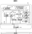
ここで、実施例について図1、5を用いて詳細に説明を加える。
図1は図2と図3から説明に必要なブロックを抜き出して、課題の解決のために必要なブロックを追加したものである。図2と図3で説明済みのものは省略し、図1で新たに追加したブロックの説明を行う。101はピックアップ11が備える光源301が記録や再生を安定して行うために必要な光ビーム照射が可能かどうかの判断を行う光源状態判断部である。安定した記録や再生を行う為の一つの条件の例として、安定した波長で光ビームを照射可能かどうか、ということが挙げられる。例えば、ホログラフィを用いた記録再生方法においては、光源301内のコヒーレンシー(可干渉性) が高いほど安定した記録や再生が可能となるが、このコヒーレンシーのレベルを測定する方法の一つとして、ウェッジプリズムを利用したコントラスト比(Contrast Ratio)を測定するという手法がある。光ビームの直進する成分と、ウェッジプリズムを通して僅かに角度をずらした成分とに分け、2つを干渉させることにより干渉縞を作り出し、干渉縞ができる箇所にラインセンサーを配置し、この干渉縞の変調度を算出してコントラスト比を算出する。この変調度の数値が高いほどコヒーレンシーが高いことを示す。なお、安定した波長で光ビーム照射が可能かどうかを判断する方法は、光源が記録や再生が行えるレーザ状態であることが判断出来る方法であれば、この方法に限定されるものではない。また、記録や再生を安定して行うために必要な光ビーム照射が可能かどうかを判断する条件も、波長の安定性に限らず、その他の条件で判断しても構わない。
102はピックアップ状態判定部であり、光源駆動部82と、シャッタ制御部87と、光源状態判断部101からの情報を元に、コントローラ89が持つ光源に関するステートマシンにおける該当するステートを判定する。ステートを判断する3つの情報源は、「光源駆動部82が光源に供給している電流量」、「シャッタ制御部87が制御しているシャッタ303の開閉状態」、「光源状態判断部101が判断した光源の安定度」、である。次にこれらの3つの情報源と図5に示した状態遷移図のステートの関係を説明する。
図5はコントローラ89が制御可能、もしくはピックアップ状態判定部102が判定可能なステートを示した状態遷移図である。なお、実線矢印507はコマンド制御での移行を示しており、点線矢印508は、シャッタ開閉によるステート移行を示しており、点線矢印509は記録再生装置への供給電源のオンオフによるステーと移行を示している。
501はOFFステートであり、記録再生装置に電力が供給されていない状態であるため、装置への電力が供給されない限り、他のステートへ移行することは出来ない。
502はOFFステート501から電力を供給することで移行可能なSLEEPステートであり、装置への電力供給がされているだけの状態で、光源への電流は供給されていない状態である。電流が供給されていない状態であるため、光ビーム照射は行われておらず、シャッタの開閉状態はどちらでも構わないが、通常は閉じている状態である。また同様の理由で光源の安定度も気にする必要がない。しばらく記録や再生を行う予定がない場合はこのSLEEPステートに移行させておくと、光源に電流が供給されていない為、消費電力の面でメリットがある。なお、SLEEPステートの中でも色々な状態が想定される。例えば、READYステートから移行した直後のSLEEPステート状態と、OFFステートから移行した直後のSLEEPステート状態では、光源への電流が供給されていないという点では同じであるが、例えば光源の波長安定性に光源の温度が関係していた場合、前者と後者ではその温度は異なるため、光源の波長が安定するREADYステートへ移行完了するまでの時間は前者の方が確実に早い。従って、SLEEPステートからWAITステートを経由してREADYステートへ移行する際、WAITに要する時間は一定ではない、ということになる。これは後述するSTANBYステートからREADYステートの移行でも同様のことが言える。
503は504のREADYステートへ移行する際に必ず経由する過渡状態のWAITステートである。WAITステートは、光源へ供給する電流量はREADYステートと同じであるが、温度などの周辺環境によって光源が安定していない可能性がある状態であり、記録や再生を行うには適さない光源状態であることを示している。安定して記録や再生が可能な光源の状態と判断されたら504のREADYステートへと移行する。なお、WAIT ステートは、過渡状態(光源安定待ち)のステートであるため、制御装置からWAITステート移行の指示は出来ない。また、WAITステートからREADYステートへ移行する条件も、記録と再生で条件が異なる場合がある。例えば、記録と比較して再生の方が光源の安定度に求められる条件が低い場合、記録と比較すると早い時間でREADYステートへ移行可能できる可能性もある。
504のREADYステートは、いつでも記録や再生が可能なステートであるが、シャッタが閉じている状態であるため、光情報記録媒体1への光ビーム照射はされていない状態である。シャッタの開閉だけですぐにRUNステートへ移行可能なため、READYステートで待機しておくとすぐに記録や再生を行うことが可能であるが、常に光源に電流が供給されている状態であるため、レーザ寿命、消費電力という観点から、このステートに留まるのは好ましくない。このステートで待機する時間を必要最小限にすることでレーザ長寿命化、低消費電力化を行うことが出来る。
505のRUNステートは、シャッタが開いている状態で、光情報記録媒体1への光ビーム照射が行われている状態、つまり記録や再生が行われている状態である。記録再生が終了した場合、シャッタを閉じれば光情報記録媒体への光ビーム照射は行われなくなる(504のREADYステート)。光源への供給電流をオンオフしてレーザをオンオフするのではなく、シャッタの開閉で光情報記録媒体への照射のオンオフを行う理由は、光源が持つWAITステートの存在である。例えば、光源に供給する電流をゼロにしてSLEEPステートに移行させてから再度RUNステートへ移行させたい場合、必ずWAITステートを経由する必要があり、WAITステートでの待ち時間が時間的に無駄となる。従って、制御装置が待ち時間なく記録や再生を行うためには、WAITステートでの時間を限りなくなしにするか、すぐにRUNステートへ移行可能なREADYステートで待機しておく必要がある。なお、
506のSTANBYステートは、RUNステート、READYステート、WAITステート、SLEEPステートから移行可能なステートであり、シャッタは閉じられており、光源には電流が供給されている状態である。READYステートとの違いは、光源への電流量である。供給電流量は、READYステートでの電流量未満でSLEEPステートより大きい、という範囲である。電流量を少なくすることで、光源で消費する電力を節約することが可能である。設定する供給電流量は幾つか考えられ、例えば記録や再生は行えないかもしれないが、安定した波長が保てるような温度状態となるような電流量としてもよいし、低消費電力となるように電流量を減らしてもよいし、READYへの移行時間を重視して電流量を増やしても良い。このようにSTANBYステートで供給する電流量を複数選択可能なようにしてもよい。
506のSTANBYステートは、RUNステート、READYステート、WAITステート、SLEEPステートから移行可能なステートであり、シャッタは閉じられており、光源には電流が供給されている状態である。READYステートとの違いは、光源への電流量である。供給電流量は、READYステートでの電流量未満でSLEEPステートより大きい、という範囲である。電流量を少なくすることで、光源で消費する電力を節約することが可能である。設定する供給電流量は幾つか考えられ、例えば記録や再生は行えないかもしれないが、安定した波長が保てるような温度状態となるような電流量としてもよいし、低消費電力となるように電流量を減らしてもよいし、READYへの移行時間を重視して電流量を増やしても良い。このようにSTANBYステートで供給する電流量を複数選択可能なようにしてもよい。
なお、STANBYステートからREADYステートへ移行する際も、WAITステートは必ず経由する。また、STANBYステートは、光源に供給する電流量を所望の設定値で設定可能なときにのみ設定されるステートであり、必ず設定可能なステートではない。
READYステートから、STANBYステート、SLEEPステートへの移行は、接続される制御装置から発行されるコマンドで可能である。WAITステートからのSLEEPステート、STANBYステートの移行も、制御装置からのコマンド指令などで可能である。つまり制御装置からコマンドで指示可能なステートは、SLEEPステート、READYステート、STANBYステートの3つとなる。OFFステートへの移行は、SLEEPステートを介さずに移行する方法もあるし、SLEEPを必ず経由して移行する方法もある。以上の説明を纏めたものが510の表である。
このように、光源の状態が安定しないと記録や再生が行えないシステムにおいて、制御装置が記録再生を指示したタイミングで記録や再生を行うためには光源に供給する電流量を常に記録や再生可能なレベルに保つ必要があるため、記録再生の停止や再開はシャッタ開閉で光情報記録媒体への記録再生を制御することが考えられる。シャッタを用いて制御した場合の問題点は常に光源に対して、記録や再生が可能なレベルの電流を供給しているので、記録再生装置の消費電力が増加するという点と、光源の寿命が早まってしまう点が挙げられる。一方、消費電力と寿命を重視し、光源に供給する電流を停止すると、光源の状態が安定するまでに時間を要する、という時間的な問題が発生する。相反するこれらの問題点を解決する為、図5で示したような状態遷移図のステートを用いて制御する。こうすることで、消費電力の面と時間的な面のバランスが取れた光源への供給電流制御が可能となる。
このステートを指示するのが制御装置91である。以下、外制御装置91のピックアップのステートの制御方法の事例を説明する。
図6は図1の光情報記録再生装置を複数台用いてデータライブラリシステムを構成し、光情報記録再生装置に接続された上位接続の機器が、複数の光情報記録媒体の記録再生制御を行うシステムである。図6において制御装置91に相当する箇所はサーバ602及びライブラリ装置制御回路605である。図1におけるスケジュール策西部103、ピックアップ状態決定部104、動作指示部105は、サーバ602及びライブラリ装置制御回路のどちらに含まれていても構わない。
データライブラリシステム601は、サーバ602を介してネットワーク603からデータ貯蔵用装置604に蓄積されたデータを光情報記録媒体に記録する。あるいは光情報記録媒体からデータを再生し、サーバ602を介してネットワーク603に送る。データライブラリシステム601は複数台の光情報記録再生装置を内蔵しており、また光情報記録媒体はデータライブラリシステム601に複数枚格納されている。ライブラリ装置制御回路605は、光情報記録媒体交換装置606と光情報記録再生装置10、10a、10b、10cを制御可能であり、光情報記録媒体のデータの記録再生指示、光情報記録媒体のロード、イジェクトなどの交換指示を行う。サーバ602は、データ貯蔵用装置604とデータライブラリシステム601を制御してネットワーク603から送られたデータを管理する。データ貯蔵用装置604は、サーバ602に制御されてネットワーク603から送られたデータの記録再生を行う。また、ライブラリ装置制御回路605は、サーバ602からの要求からだけではなく、ネットワーク603を経由での要求によって制御されてもよい。
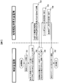
なお、想定するシステムの一例として、データ貯蔵用装置が記録用のデータを蓄積し、ある一定量に到達した場合に、光情報記録再生媒体へデータを記録する、というシステムを想定する。次に図7を用いてはスケジュール作成を前提とした光情報記録媒体への記録動作例を示したシーケンスの一例の説明を行う。最初に全ステップの流れを説明し、詳細な説明が必要な箇所については後で個別に説明を加える。
ステップ701で、図1における制御装置のスケジュール作成部103では記録スケジュールの作成を行う。スケジュールとは、制御装置が光情報記録再生装置に装着された光情報記録媒体に対してデータの記録や再生、ロードやイジェクトなどの動作をどの順序で、どのタイミングで行うか、の計画である。なお、スケジューリングの具体例については、図6、図8を用いて後で説明を加える。
ステップ701で、図1における制御装置のスケジュール作成部103では記録スケジュールの作成を行う。スケジュールとは、制御装置が光情報記録再生装置に装着された光情報記録媒体に対してデータの記録や再生、ロードやイジェクトなどの動作をどの順序で、どのタイミングで行うか、の計画である。なお、スケジューリングの具体例については、図6、図8を用いて後で説明を加える。
ステップ702で、作成した記録スケジュールに従い、制御装置のピックアップ状態決定部104で移行すべき光源ステートを決定して動作指示部105に伝達する。ここでは光情報記録再生装置に対し、図5の状態遷移図におけるSLEEPステートからREADYステートへの移行を指示する。なお、指示タイミングの事例については図8を用いて後で説明を加える。
ステップ703で、光情報記録再生装置はREADYステートの移行指示を受けたことにより、WAITステートに入り、光源が記録可能に状態になるのを待つ。
ステップ704で、制御装置の動作指示部105は、光情報記録再生装置のピックアップのステートをポーリングなどでモニタリングし、READYステートへ移行するのを待つ。光情報記録再生装置の入出力制御部90は現在の光源ステートを制御装置の動作指示部105へ返却可能である。制御装置はREADYステートへの移行が確認出来たら、記録コマンドを動作指示部105経由で光情報記録再生装置へ発行し、記録指示を出す。
ステップ705で、光情報記録再生装置は記録コマンドを受け、光情報記録媒体へ記録するデータの準備が整い次第、シャッタを開き光情報記録媒体へ光ビームを照射することで記録動作を開始し、RUNステートへ移行する。
ステップ706で、記録終了後シャッタを閉じて記録動作を終了し、READYステートへ移行する。
ステップ707で、スケジュール作成部103で作成した次のスケジュールに従ったステート選択をピックアップ状態決定部104で行う。なお、このステップ707のスケジュール作成事例については図9、図10を用いて後で説明を加える。以上が、全ステップの流れを説明で、以降は説明が必要な箇所について個別に説明を行う。
まずは、ステップ701におけるスケジューリングの具体例について図6、図8を用いて説明を加える。想定するシステムの一例として、データ貯蔵用装置604に記録されたデータ量がある一定量(Xバイト)に到達した場合に、光情報記録再生媒体へデータを記録する、というシステムを想定する。このようなシステムの記録スケジュールの作成例はいくつか考えられるが、例えばデータ貯蔵用装置604に蓄積済みのデータ量と、サーバが管理しているこれから記録するデータの記録予定量や、キューイングされている記録スケジュールなどから、データ貯蔵用装置に蓄積されるデータ量は予測がある程度可能である。また再生スケジュールについても、同様の考え方で予測が可能である。記録スケジュールを作成可能な装置は、サーバ602(案1)、ライブラリ装置制御回路(案2)の2つが考えられる。案1から説明を加える。案1では、サーバ602がデータ貯蔵用装置604へデータを記録する際、予定記録データ量と実記録速度から「今回の記録でXバイトに到達しそうかどうか」、「Xバイトに到達するのはいつか」、などは、サーバ602である程度予測可能である。
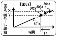
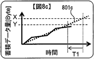
これについて図8aを用いて説明する。縦軸に蓄積データ量、横軸に時間を取ると、蓄積データ量を時間毎にプロットした線が801aの実線部分である。予定されている記録データ量から一定量(Xバイト)に到達するか否かは単純な加算で予測可能であり、また記録速度が一定であった場合の予想到達時間も801aの実線の線形補間した点線部分などから予測可能である。また図8bのように、データ蓄積量の変化をリアルタイムに検知し、Xバイト予測到達時間を更新する手法も考えられる。変化前が801aで変化後は801bである。もちろん線形補間以外の予測方法で予測してもよく、例えば図8cのように線形補間ではなく、各データ増加量の傾きを平均するように補間してもよく、その予測方法は問わない。
これについて図8aを用いて説明する。縦軸に蓄積データ量、横軸に時間を取ると、蓄積データ量を時間毎にプロットした線が801aの実線部分である。予定されている記録データ量から一定量(Xバイト)に到達するか否かは単純な加算で予測可能であり、また記録速度が一定であった場合の予想到達時間も801aの実線の線形補間した点線部分などから予測可能である。また図8bのように、データ蓄積量の変化をリアルタイムに検知し、Xバイト予測到達時間を更新する手法も考えられる。変化前が801aで変化後は801bである。もちろん線形補間以外の予測方法で予測してもよく、例えば図8cのように線形補間ではなく、各データ増加量の傾きを平均するように補間してもよく、その予測方法は問わない。
次に案2について説明を加える。案2では、ライブラリ装置制御回路605が、データ貯蔵用装置604に蓄積されるデータ量の監視を行う必要があるが、サーバ602から予測に必要なデータを供給してもらうか、データ貯蔵用装置604のデータの増加スピードを監視することにより、案1と同様の予測が可能である。
次に、ステップ702における指示タイミングについて図8を用いて説明を加える。
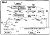
図8は、図7の702におけるSLEEPステートからREADYステートへの移行の指示を行うタイミングの事例である。図8aの一部は上記で説明したので省略し、説明していない箇所のみ説明を加える。一定の蓄積データ量のYバイトとは、線形補間した線での予測において、Xバイトから時間T1だけ前に到達するであろう蓄積データ量である。時間T1とはSLEEPステートから、WAITステートを経由して最終的にREADYステートになるまでの時間である。つまり、光情報記録再生装置を使用側からみた時の記録再生可能となるまでの待ち時間となる。図8dを用いてさらに説明を加える。ステップ801dで、Xバイト到達予測時間から時間T1より前の容量(Yバイト)を推定する。またその予想到達時間はXバイト到達予想時間-T1となる。ステップ802dでは蓄積データ量が、予測したYバイトに到達したか否かを判断する(802a)。Yバイトに到達した場合は、SLEEPステートまたはSTANBYステートからREADYステートへ移行を指示する(ステップ803d)。
予定時間においてYバイトに到達していない場合、記録が停止状態(=蓄積データの増加がない場合)かどうかを判断し(ステップ807d)、記録停止状態の場合は、SLEEPまたはSTANBYステートへの移行コマンドを発行し(ステップ811d)、処理終了となる。記録停止状態ではない場合は、現在の転送速度や予定記録データ量などを元にYバイトの到達予測時間を再計算して予測時間を補正する(ステップ809d)。ステップ803dでREADYステートへの移行指示を行った後、ステップ804dでXバイトに到達したかどうか判断する。Xバイトに到達した場合は、ステップ805dにてREADYステート状態かどうかを判断する。光情報記録再生装置がまだREADYステートではない場合、READYステートになるまで待つ。READYステートであった場合は、制御装置は、記録コマンドを光情報記録再生装置に対して発行し(ステップ806d)、処理終了となる。予定時間においてXバイトに到達していない場合(803a)、記録が停止状態(=蓄積データの増加がない場合)かどうかを判断し(ステップ808d)、記録停止状態の場合は、SLEEPステートまたはSTANBYステートへの移行コマンドを発行し(ステップ811d)、処理終了となる。記録停止状態ではない場合は、現在の転送速度や予定記録データ量などを元にXバイトの到達予測時間を再計算して予測時間を予測する(ステップ810d)。このように、Xバイト到達予測時間より、時間T1だけ早い時間にステップ803dでREADY移行指示を出すことにより、WAITステートに要する時間を意識することなく制御装置は記録を行いたいタイミングで記録コマンドを発行することが可能となる(ステップ806d)。また図8eのように予測を使用せず、Xバイト到達時(804a)の時点でREADYステート移行の指示を出しても良い。図8eは、図8dでステップ804dのYESのパスと同じ動作となるが、データ貯蔵用装置から光情報記録媒体へデータを記録する際、データの暗号化やパリティの付加、その他必要な処理を行うためのデータの加工に時間を要する場合、WAITステートに要する時間と平行して処理を実行できるため有効である。
図8は、図7の702におけるSLEEPステートからREADYステートへの移行の指示を行うタイミングの事例である。図8aの一部は上記で説明したので省略し、説明していない箇所のみ説明を加える。一定の蓄積データ量のYバイトとは、線形補間した線での予測において、Xバイトから時間T1だけ前に到達するであろう蓄積データ量である。時間T1とはSLEEPステートから、WAITステートを経由して最終的にREADYステートになるまでの時間である。つまり、光情報記録再生装置を使用側からみた時の記録再生可能となるまでの待ち時間となる。図8dを用いてさらに説明を加える。ステップ801dで、Xバイト到達予測時間から時間T1より前の容量(Yバイト)を推定する。またその予想到達時間はXバイト到達予想時間-T1となる。ステップ802dでは蓄積データ量が、予測したYバイトに到達したか否かを判断する(802a)。Yバイトに到達した場合は、SLEEPステートまたはSTANBYステートからREADYステートへ移行を指示する(ステップ803d)。
予定時間においてYバイトに到達していない場合、記録が停止状態(=蓄積データの増加がない場合)かどうかを判断し(ステップ807d)、記録停止状態の場合は、SLEEPまたはSTANBYステートへの移行コマンドを発行し(ステップ811d)、処理終了となる。記録停止状態ではない場合は、現在の転送速度や予定記録データ量などを元にYバイトの到達予測時間を再計算して予測時間を補正する(ステップ809d)。ステップ803dでREADYステートへの移行指示を行った後、ステップ804dでXバイトに到達したかどうか判断する。Xバイトに到達した場合は、ステップ805dにてREADYステート状態かどうかを判断する。光情報記録再生装置がまだREADYステートではない場合、READYステートになるまで待つ。READYステートであった場合は、制御装置は、記録コマンドを光情報記録再生装置に対して発行し(ステップ806d)、処理終了となる。予定時間においてXバイトに到達していない場合(803a)、記録が停止状態(=蓄積データの増加がない場合)かどうかを判断し(ステップ808d)、記録停止状態の場合は、SLEEPステートまたはSTANBYステートへの移行コマンドを発行し(ステップ811d)、処理終了となる。記録停止状態ではない場合は、現在の転送速度や予定記録データ量などを元にXバイトの到達予測時間を再計算して予測時間を予測する(ステップ810d)。このように、Xバイト到達予測時間より、時間T1だけ早い時間にステップ803dでREADY移行指示を出すことにより、WAITステートに要する時間を意識することなく制御装置は記録を行いたいタイミングで記録コマンドを発行することが可能となる(ステップ806d)。また図8eのように予測を使用せず、Xバイト到達時(804a)の時点でREADYステート移行の指示を出しても良い。図8eは、図8dでステップ804dのYESのパスと同じ動作となるが、データ貯蔵用装置から光情報記録媒体へデータを記録する際、データの暗号化やパリティの付加、その他必要な処理を行うためのデータの加工に時間を要する場合、WAITステートに要する時間と平行して処理を実行できるため有効である。
次に、ステップ707における指示タイミングについて図9、図10を用いて説明を加える。図9は記録が終了した際、次に移行するステートをどのようにして決定するかを説明するための図である。記録901が実行中はステートはRUNステート(902)であり、シャッタを閉じることでRUNステートからREADYステートへ移行する。その後、予定されている記録スケジュールに応じて、ステートを制御する事例を説明する。まず903~905のT1~T3の時間の定義を行う。903は図5の状態遷移図におけるSLEEPステートからWAITステートを経由して、READYステートへ以降完了するまでの時間である。904は図5の状態遷移図におけるSTANBYステートからWAITステートを経由して、READYステートに移行完了するまでに要する時間である。なお、図5で説明した通り、T1やT2は光源の状態により可変となるが、ここでは最大でかかる時間を想定する。905は記録901が終了してから次の記録が開始されるまでの待ち時間である。なお、902のRUNステートからシャッタ閉で移行するREADYステートの時間幅は、次のステート移行指示のタイミングによって異なる。まず906と907のSLEEPステートに移行する事例から説明を加える。
906の事例は、T3の時間がT1よりも長い場合である。この場合は次の記録までの時間に余裕があるため、記録開始T1前までにREADYステートへの移行を指示すれば、再度WAITステートを経由しても、次の記録開始タイミングまでにはREADYステートへ復帰が可能であり、制御装置側は待ち時間なく記録開始が可能となる。また光情報記録再生装置側は、光源への供給電流を断つことで、光源の長寿命化と消費電力の低減に貢献する。
907の事例は、SLEEPステートへ移行した後は、次の記録の予定がないため、図8で説明した記録開始予測などで次のスケジュールが決定するまでは、ずっとSLEEPステートの状態である。場合によっては、装置の電源をオフにしてOFFステートへ移行することも考えられるが、光源の視点から言うとどちらも供給電流はゼロであるので差異はない。
908の事例は、T3の時間がT1よりも短く、T2よりも長い場合である。この場合は、SLEEPステートへ移行すると次の記録開始までに光源の記録の準備が間に合わないが、STANBYステートへの移行ならば、記録開始T2前までにREADYステートへの移行を指示すれば、再度WAITステートを経由しても、次の記録開始タイミングまでにはREADYステートへ復帰が可能であり、制御装置側は待ち時間なく記録開始が可能となる。また光情報記録再生装置側は、光源への供給電流を抑えることで、光源の長寿命化と消費電力の低減を実現する。
909の事例は、T3の時間がT1よりもT2よりも短い場合である。この場合は、SLEEPステートや、STANBYステートに移行すると次の記録開始までに光源の記録の準備が間に合わないため、READYステートの維持を指示することで、制御装置側は待ち時間なく記録開始が可能となる。
906の事例は、T3の時間がT1よりも長い場合である。この場合は次の記録までの時間に余裕があるため、記録開始T1前までにREADYステートへの移行を指示すれば、再度WAITステートを経由しても、次の記録開始タイミングまでにはREADYステートへ復帰が可能であり、制御装置側は待ち時間なく記録開始が可能となる。また光情報記録再生装置側は、光源への供給電流を断つことで、光源の長寿命化と消費電力の低減に貢献する。
907の事例は、SLEEPステートへ移行した後は、次の記録の予定がないため、図8で説明した記録開始予測などで次のスケジュールが決定するまでは、ずっとSLEEPステートの状態である。場合によっては、装置の電源をオフにしてOFFステートへ移行することも考えられるが、光源の視点から言うとどちらも供給電流はゼロであるので差異はない。
908の事例は、T3の時間がT1よりも短く、T2よりも長い場合である。この場合は、SLEEPステートへ移行すると次の記録開始までに光源の記録の準備が間に合わないが、STANBYステートへの移行ならば、記録開始T2前までにREADYステートへの移行を指示すれば、再度WAITステートを経由しても、次の記録開始タイミングまでにはREADYステートへ復帰が可能であり、制御装置側は待ち時間なく記録開始が可能となる。また光情報記録再生装置側は、光源への供給電流を抑えることで、光源の長寿命化と消費電力の低減を実現する。
909の事例は、T3の時間がT1よりもT2よりも短い場合である。この場合は、SLEEPステートや、STANBYステートに移行すると次の記録開始までに光源の記録の準備が間に合わないため、READYステートの維持を指示することで、制御装置側は待ち時間なく記録開始が可能となる。
以上のように、次の記録開始までの時間とREADYステート移行に要する時間を考慮して、記録終了時に移行するステートを指示することで、制御装置側から見ると待ち時間なく記録開始が可能というメリットがあり、また光情報記録再生装置側から見ると、光源への供給電流を断つことで、光源の長寿命化と消費電力の低減を実現できる、というメリットある。なお、記録の事例を例に挙げて説明を行ったが、これが再生の事例であっても、記録や再生が混在する事例でも同様に考えることが可能で同じ効果を得ることが出来る。
図10は光情報記録媒体のロード、イジェクトといった光情報記録媒体の交換動作に着目した時のステート移行の指示方法である。最初に1004と1005の説明を行う。1004は既存のATAPI(AT Attachment Packet Interface)のパケットコマンドの
START STOP UNITコマンド(Operation Code(1Bh))の定義を示しており、ATAPI対応機器はこのコマンドを用いてロード、イジェクトを行う。Rsvで示した黒枠は現時点で未定義の領域であり、このように既存のコマンドの定義の中で未定義ビットがある場合がある。この未定義を利用してステートを移行の指示を行うことを考える。Rsvで示した領域の中の2ビットを使用して、例えばByte5のbit3,4の2ビットを用いて1005のような定義を行う。00は現在のステートを維持、01はSLEEPステートへ移行、10はSTANBYステートへ移行、11はREADYステートへ移行、の指示内容となる。なお、この定義は未定義の場所であればどこであっても構わない。なお、本事例ではシャッタ制御は制御装置ではなく、光情報記録再生装置で行うことを考えるため、RUNステートへの移行指示は含まれていないが、シャッタ制御を制御装置で行うことを考えた場合は、3ビットを用いて、RUNステートへ移行する定義を追加しても良い。
1001の事例は、ライブラリ装置制御回路605が光情報記録媒体交換装置606と光情報記録再生装置10に対して、新規に光情報記録媒体1のロードを行う場合である。ライブラリ装置制御回路605が、光情報記録媒体1のロードを行う場合、1004と1005で定義されたコマンドを用いれば、1回のコマンド指示で光情報記録媒体交換装置606に対してはロード指示を与え、光情報記録再生装置10に対しては、READYステートへの移行を指示可能となる。1002と1003の事例は光情報記録再生装置10にロード済みの光情報記録媒体1のイジェクトを行う場合である。共にイジェクトを行うという点では同じであるが、イジェクト後に新たな光情報記録媒体をロードするか否かで1005で指定する内容が異なる。1002の事例はイジェクト後も新たな光情報記録媒体のロードを行い記録の予定があるため、READYステート維持を指示し、1003の事例ではイジェクト後は新たな光情報記録媒体のロード予定がないため、SLEEPステートを指示する。現在装着されている光情報記録媒体のイジェクト指示と同時にピックアップのステート指示を行うことで、ライブラリ装置制御回路から見た記録再生制御の効率化と光情報記録再生装置の省電力化、長寿命化をすばやく指示することが可能となる。
START STOP UNITコマンド(Operation Code(1Bh))の定義を示しており、ATAPI対応機器はこのコマンドを用いてロード、イジェクトを行う。Rsvで示した黒枠は現時点で未定義の領域であり、このように既存のコマンドの定義の中で未定義ビットがある場合がある。この未定義を利用してステートを移行の指示を行うことを考える。Rsvで示した領域の中の2ビットを使用して、例えばByte5のbit3,4の2ビットを用いて1005のような定義を行う。00は現在のステートを維持、01はSLEEPステートへ移行、10はSTANBYステートへ移行、11はREADYステートへ移行、の指示内容となる。なお、この定義は未定義の場所であればどこであっても構わない。なお、本事例ではシャッタ制御は制御装置ではなく、光情報記録再生装置で行うことを考えるため、RUNステートへの移行指示は含まれていないが、シャッタ制御を制御装置で行うことを考えた場合は、3ビットを用いて、RUNステートへ移行する定義を追加しても良い。
1001の事例は、ライブラリ装置制御回路605が光情報記録媒体交換装置606と光情報記録再生装置10に対して、新規に光情報記録媒体1のロードを行う場合である。ライブラリ装置制御回路605が、光情報記録媒体1のロードを行う場合、1004と1005で定義されたコマンドを用いれば、1回のコマンド指示で光情報記録媒体交換装置606に対してはロード指示を与え、光情報記録再生装置10に対しては、READYステートへの移行を指示可能となる。1002と1003の事例は光情報記録再生装置10にロード済みの光情報記録媒体1のイジェクトを行う場合である。共にイジェクトを行うという点では同じであるが、イジェクト後に新たな光情報記録媒体をロードするか否かで1005で指定する内容が異なる。1002の事例はイジェクト後も新たな光情報記録媒体のロードを行い記録の予定があるため、READYステート維持を指示し、1003の事例ではイジェクト後は新たな光情報記録媒体のロード予定がないため、SLEEPステートを指示する。現在装着されている光情報記録媒体のイジェクト指示と同時にピックアップのステート指示を行うことで、ライブラリ装置制御回路から見た記録再生制御の効率化と光情報記録再生装置の省電力化、長寿命化をすばやく指示することが可能となる。
なお、図9の901の記録終了後に移行するステートの指示方法も図10の1004、1005の事例のように記録コマンドの空きビットを利用して行うことが出来る。通常、記録コマンドは連続で複数回発行されることが多く、そのコマンドはキューイングされ、記録コマンド発行タイミングとその記録コマンドに対応した実際の光情報記録媒体へのデータ記録終了までには時間差がある。従って、空きビットで指定されたステートへの移行は、コマンド受け付け時ではなく、当該の記録コマンドに対する光情報記録媒体へのデータ記録が終了後となる。
このように、光源が実際に最適な状態となるまでに時間を要する光情報記録再生装置を用いて制御装置が記録再生を行う場合において、記録や再生スケジュールを管理している制御装置側が光情報記録再生装置のピックアップのステート制御を行うことで、制御装置側からみた記録再生をタイミングよく行うことが可能で、更に光情報記録再生装置側からみた光情報記録再生装置の省電力化、光源の長寿命化を実現可能である。
最後にピックアップ状態を決定する際の処理フローを図11aに纏めた。「光源駆動部82が光源に供給している電流量」を判断するステップ1101a、「シャッタ制御部87が制御しているシャッタ303の開閉状態」を判断するステップ1102a、「光源状態判断部101が判断した光源の安定度」を判断するステップ1103a、これらの情報を元に「ピックアップ11の状態」を判定するステップ1104aの各ステップを実行することでピックアップ状態が判定可能である。図11bは制御装置の指示で光源への電流が供給されるまでのフローである。記録再生スケジュールを作成し(ステップ1101b)、スケジュールに応じたピックアップ状態の移行ステートを指示し(ステップ1102b)、移行ステートに応じた光源へ電流を供給する(ステップ1103b)。
なお、本発明は上記した実施例に限定されるものではなく、様々な変形例が含まれる。例えば、上記した実施例は本発明を分かりやすく説明するために詳細に説明したものであり、必ずしも説明した全ての構成を備えるものに限定されるものではない。また、ある実施例の構成の一部を他の実施例の構成に置き換えることが可能であり、また、ある実施例の構成に他の実施例の構成を加えることも可能である。また、各実施例の構成の一部について、他の構成の追加・削除・置換をすることが可能である。
また、上記の各構成、機能、処理部、処理手段等は、それらの一部又は全部を、例えば集積部で設計する等によりハードウェアで実現してもよい。また、上記の各構成、機能等は、プロセッサがそれぞれの機能を実現するプログラムを解釈し、実行することによりソフトウェアで実現してもよい。各機能を実現するプログラム、テーブル、ファイル等の情報は、メモリや、ハードディスク、SSD(Solid State Drive)等の記録装置、または、ICカード、SDカード等の記録媒体に置くことができる。
また、制御線や情報線は説明上必要と考えられるものを示しており、製品上必ずしも全ての制御線や情報線を示しているとは限らない。実際には殆ど全ての構成が相互に接続されていると考えてもよい。
1・・・光情報記録媒体、10・・・光情報記録再生装置、11・・・ピックアップ、
12・・・再生用参照光光学系、13・・・ディスクCure光学系、
14・・・ディスク回転角度検出用光学系、81・・・アクセス制御部、
82・・・光源駆動部、83・・・サーボ信号生成部、
84・・・サーボ制御部、85・・・信号処理部、86・・・信号生成部、
87・・・シャッタ制御部、88・・・ディスク回転モータ制御部、
89・・・コントローラ、90・・・入出力制御部、91・・・制御装置、
301・・・光源、303・・・シャッタ、306・・・信号光、307・・・参照光、
308・・・ビームエキスパンダ、309・・・フェーズ(位相)マスク、
310・・・リレーレンズ、311・・・PBSプリズム、
312・・・空間光変調器、313・・・リレーレンズ、314・・・空間フィルタ、
315・・・対物レンズ、316・・・偏光方向変換素子、320・・・アクチュエータ、
321・・・レンズ、322・・・レンズ、323・・・アクチュエータ、
324・・・ミラー、325・・・光検出器、406・・・回折された信号光
12・・・再生用参照光光学系、13・・・ディスクCure光学系、
14・・・ディスク回転角度検出用光学系、81・・・アクセス制御部、
82・・・光源駆動部、83・・・サーボ信号生成部、
84・・・サーボ制御部、85・・・信号処理部、86・・・信号生成部、
87・・・シャッタ制御部、88・・・ディスク回転モータ制御部、
89・・・コントローラ、90・・・入出力制御部、91・・・制御装置、
301・・・光源、303・・・シャッタ、306・・・信号光、307・・・参照光、
308・・・ビームエキスパンダ、309・・・フェーズ(位相)マスク、
310・・・リレーレンズ、311・・・PBSプリズム、
312・・・空間光変調器、313・・・リレーレンズ、314・・・空間フィルタ、
315・・・対物レンズ、316・・・偏光方向変換素子、320・・・アクチュエータ、
321・・・レンズ、322・・・レンズ、323・・・アクチュエータ、
324・・・ミラー、325・・・光検出器、406・・・回折された信号光
Claims (18)
- ホログラフィを用いて情報を記録する光情報記録再生システムであって、
光情報記録媒体のデータ記録再生を行う光情報記録再生装置と、
前記光情報記録再生装置を制御するの制御装置と、を有し、
前記光情報記録再生装置は、レーザ光源を有するピックアップと、該ピックアップを制御するコントローラを備え、
前記制御装置は、前記コントローラに対し前記ピックアップの状態遷移を指示するピックアップ状態指示部を備える
こと特徴とする光情報記録再生システム。 - 請求項1に記載の光情報記録再生システムであって、
前記コントローラは、
前記ピックアップが具備するレーザ光源の発光安定度、
前記レーザ光源への電流供給状態、
および、前記ピックアップが具備し、前記レーザ光源より発光される光ビームを遮る役割を果たすシャッタの開閉状態
に基づき前記ピックアップの状態遷移を制御する
ことを特徴とする光情報記録再生システム。 - 請求項2に記載の光情報記録再生システムであって、
前記コントローラは、
前記制御装置のピックアップ状態指示部が指示したピックアップ状態に対応した量の電流が前記レーザ光源へ供給されるように制御する
ことを特徴とする光情報記録再生システム。 - 請求項3に記載の光情報記録再生システムであって、
前記コントローラは、
前記レーザ光源に対する電流の供給が停止され、かつ前記シャッタが閉じられた状態にあるSLEEPステート、
前記レーザ光源に対して記録又は再生に必要な電流が供給され、かつ前記レーザ光源状態が安定した記録または再生を行うための条件を満足している状態にあり、さらに前記シャッタが閉じられた状態にあるREADYステート、
前記レーザ光源に対して記録又は再生に必要な電流が供給され、かつ前記レーザ光源状態が記録または再生を行うための条件を満足していない状態にあり、さらに前記シャッタが閉じられた状態にあるWAITステート、
および前記レーザ光源に対して記録又は再生に必要な電流が供給され、かつ前記レーザ光源状態が安定した記録または再生を行うための条件を満足している状態にあり、さらに前記シャッタが開かれ状態にあるRUNステートを、
前記ピックアップの状態遷移を管理するためのステートに含む
ことを特徴とした光情報記録再生システム。 - 請求項4に記載の光情報記録再生システムであって、
前記コントローラは、
前記レーザ光源に対して記録又は再生を行うには十分ではない電流が供給され、かつ前記シャッタが閉じられた状態にあるSTANBYステートを
前記ピックアップの状態遷移を管理するためのステートに含む
ことを特徴とした光情報記録再生システム。 - 請求項5に記載の光情報記録再生システムであって、
前記コントローラは、
前記STANBYステートにおける前記レーザ光源への供給電流量を複数設定可能な
ことを特徴とする光情報記録再生システム。 - 請求項6に記載の光情報記録再生システムであって、
前記制御装置から前記光情報記録再生装置に対して発行される
記録を指示するコマンド1、
再生を指示するコマンド2、
前記光情報記録媒体のロードを指示するコマンド3、
前記光情報記録媒体のイジェクトを指示するコマンド4、
ステート移行指示専用のオペレーションコードを持つコマンド5、
のうちいずれか、または、すべてのコマンドに、
ピックアップの状態指示情報が含まれる
ことを特徴とする光情報記録再生システム。 - 請求項7に記載の光情報記録再生システムであって、
前記コントローラが前記ピックアップの状態を制御するタイミングが、
コマンド1、2に対しては、前記光情報記録媒体に指示したデータ長分の記録再生が終了後、
コマンド3、4、5に対しては、コマンドが発行されると同時、である
ことを特徴とする光情報記録再生システム。 - 請求項1に記載の光情報記録再生システムであって、
前記ピックアップの状態を判定するピックアップ状態判定部を前記光情報記録再生装置に備え、
前記ピックアップ状態判定部は、
前記ピックアップが具備するレーザ光源の発光安定度、
前記レーザ光源への電流供給状態、
および、前記シャッタの開閉状態
に基づき前記ピックアップの状態遷移を判定する
ことを特徴とする光情報記録再生システム。 - 光情報記録媒体のデータ記録再生をピックアップを用いて行う光情報記録再生装置と、前記光情報記録再生装置の制御装置とを有した光情報記録再生システムにおけるピックアップ状態管理方法において、
前記制御装置が前記光情報記録再生装置へピックアップの状態遷移を指示し、前記光情報記録再生装置は前記指示に従いピックアップの状態遷移を制御すること
を特徴とするピックアップ状態管理方法。 - 請求項10に記載のピックアップ状態管理方法であって、
前記ピックアップは光ビームの照射を行う為の光源と、光ビームを遮る役割を果たすシャッタを用いてデータの記録と再生を行う場合、
前記ピックアップの状態遷移を、光源の発光安定度、光源への電流供給状態、およびシャッタの開閉状態
に基づき制御すること
を特徴とするピックアップ状態管理方法。 - 請求項11に記載のピックアップ状態管理方法であって、
前記制御装置が指示したピックアップ状態に対応した電流量を光源へ供給するように制御する
ことを特徴とするピックアップ状態管理方法。 - 請求項12に記載のピックアップ状態管理方法であって、
前記ピックアップの状態遷移を管理するためのステートは、
前記光源に対する電流の供給が停止され、かつ前記シャッタが閉じられた状態にあるSLEEPステート、
前記光源に対して記録又は再生に必要な電流が供給され、かつ前記光源状態が安定した記録または再生を行うための条件を満足している状態にあり、さらに前記シャッタが閉じられた状態にあるREADYステート、
前記光源に対して記録又は再生に必要な電流が供給され、かつ前記光源状態が記録または再生を行うための条件を満足していない状態にあり、さらに前記シャッタが閉じられた状態にあるWAITステート、
および前記光源に対して記録又は再生に必要な電流が供給され、かつ前記光源状態が安定した記録または再生を行うための条件を満足している状態にあり、さらに前記シャッタが開かれ状態にあるRUNステートを、
含むことを特徴としたピックアップ状態管理方法。 - 請求項13に記載のピックアップ状態管理方法であって、
前記ピックアップの状態遷移を管理するためのステートは、
前記光源に対して記録又は再生を行うには十分ではない電流が供給され、かつ前記シャッタが閉じられた状態にあるSTANBYステートを
含むことを特徴としたピックアップ状態管理方法。 - 請求項14に記載のピックアップ状態管理方法であって、
前記STANBYステートにおける前記光源への供給電流量を複数設定可能なこと
を特徴とするピックアップ状態管理方法。 - 請求項15に記載のピックアップ状態管理方法であって、
前記制御装置から前記光情報記録再生装置に対して発行される
記録を指示するコマンド1、
再生を指示するコマンド2、
前記光情報記録媒体のロードを指示するコマンド3、
前記光情報記録媒体のイジェクトを指示するコマンド4、
ステート移行指示専用のオペレーションコードを持つコマンド5、
のうちいずれか、または、すべてのコマンドに、
ピックアップの状態指示情報が含まれること
を特徴とするピックアップ状態管理方法。 - 請求項16に記載のピックアップ状態管理方法であって、
前記ピックアップの状態を制御するタイミングが、
コマンド1、2に対しては、前記光情報記録媒体に指示したデータ長分の記録再生が終了後、
コマンド3、4、5に対しては、コマンドが発行されると同時、であること
を特徴とするピックアップ状態管理方法。 - 請求項10に記載のピックアップ状態管理方法であって、
前記ピックアップは光ビームの照射を行う為の光源と、光ビームを遮る役割を果たすシャッタを用いてデータの記録と再生を行う場合、
前記ピックアップの状態を、光源の発光安定度、光源への電流供給状態、およびシャッタの開閉状態
に基づき判定すること
を特徴とするピックアップ状態管理方法。
Priority Applications (1)
| Application Number | Priority Date | Filing Date | Title |
|---|---|---|---|
| PCT/JP2012/082124 WO2014091569A1 (ja) | 2012-12-12 | 2012-12-12 | 光情報記録再生システムおよびピックアップ状態管理方法 |
Applications Claiming Priority (1)
| Application Number | Priority Date | Filing Date | Title |
|---|---|---|---|
| PCT/JP2012/082124 WO2014091569A1 (ja) | 2012-12-12 | 2012-12-12 | 光情報記録再生システムおよびピックアップ状態管理方法 |
Publications (1)
| Publication Number | Publication Date |
|---|---|
| WO2014091569A1 true WO2014091569A1 (ja) | 2014-06-19 |
Family
ID=50933893
Family Applications (1)
| Application Number | Title | Priority Date | Filing Date |
|---|---|---|---|
| PCT/JP2012/082124 Ceased WO2014091569A1 (ja) | 2012-12-12 | 2012-12-12 | 光情報記録再生システムおよびピックアップ状態管理方法 |
Country Status (1)
| Country | Link |
|---|---|
| WO (1) | WO2014091569A1 (ja) |
Citations (5)
| Publication number | Priority date | Publication date | Assignee | Title |
|---|---|---|---|---|
| JPH046636A (ja) * | 1990-04-25 | 1992-01-10 | Nippon Telegr & Teleph Corp <Ntt> | 光記録再生装置 |
| JPH0982039A (ja) * | 1995-09-18 | 1997-03-28 | Sony Corp | 情報記録方法および追記型光ディスク記録方法 |
| JP2006106322A (ja) * | 2004-10-05 | 2006-04-20 | Sony Corp | ホログラム記録装置及びホログラム記録方法 |
| JP2007004041A (ja) * | 2005-06-27 | 2007-01-11 | Sony Corp | ホログラム装置 |
| JP2007027517A (ja) * | 2005-07-19 | 2007-02-01 | Sanyo Electric Co Ltd | 半導体レーザー装置及びそれを用いたホログラム装置。 |
-
2012
- 2012-12-12 WO PCT/JP2012/082124 patent/WO2014091569A1/ja not_active Ceased
Patent Citations (5)
| Publication number | Priority date | Publication date | Assignee | Title |
|---|---|---|---|---|
| JPH046636A (ja) * | 1990-04-25 | 1992-01-10 | Nippon Telegr & Teleph Corp <Ntt> | 光記録再生装置 |
| JPH0982039A (ja) * | 1995-09-18 | 1997-03-28 | Sony Corp | 情報記録方法および追記型光ディスク記録方法 |
| JP2006106322A (ja) * | 2004-10-05 | 2006-04-20 | Sony Corp | ホログラム記録装置及びホログラム記録方法 |
| JP2007004041A (ja) * | 2005-06-27 | 2007-01-11 | Sony Corp | ホログラム装置 |
| JP2007027517A (ja) * | 2005-07-19 | 2007-02-01 | Sanyo Electric Co Ltd | 半導体レーザー装置及びそれを用いたホログラム装置。 |
Similar Documents
| Publication | Publication Date | Title |
|---|---|---|
| JP5358530B2 (ja) | 光情報記録再生装置及び再生装置 | |
| JP5487057B2 (ja) | 再生装置及び再生方法 | |
| JP5096191B2 (ja) | 光ピックアップおよび、それを用いた光情報再生装置および光情報記録再生装置 | |
| JP6134738B2 (ja) | 光情報記録再生装置、光情報記録再生方法 | |
| JP2016038480A (ja) | ホログラフィックメモリ装置 | |
| JP4969558B2 (ja) | 光情報再生装置、光情報記録再生装置 | |
| JPWO2013175525A1 (ja) | 光情報記録再生装置、記録条件調整方法及び光情報記録媒体 | |
| WO2014091569A1 (ja) | 光情報記録再生システムおよびピックアップ状態管理方法 | |
| JP5277009B2 (ja) | 光情報記録方法および記録装置 | |
| CN104103294A (zh) | 光信息记录再现装置 | |
| JP2014229131A (ja) | データ記録再生システム及びデータ記録制御方法 | |
| CN103123792A (zh) | 光信息记录再现装置和方法、光信息记录介质 | |
| JP5557787B2 (ja) | 光情報再生装置、光情報記録再生装置 | |
| JP5222524B2 (ja) | 光情報記録媒体、光情報記録再生装置、及び光情報記録再生方法 | |
| JP2006344278A (ja) | ホログラム装置及びホログラム記録再生方法 | |
| JP4357557B2 (ja) | 光ヘッド,および光ディスク装置 | |
| JP5647965B2 (ja) | 光情報記録再生装置、光情報記録装置、光情報記録再生方法、光情報記録媒体 | |
| JP2012069207A (ja) | ホログラフィを用いたホログラフィックメモリ | |
| JP2017004576A (ja) | 光情報記録再生装置および光情報記録再生方法 | |
| JP2015130215A (ja) | 光情報記録装置および光情報記録方法 | |
| JP5542739B2 (ja) | ホログラフィックメモリ再生装置、およびホログラフィックメモリ再生方法 | |
| JP2012243355A (ja) | 光情報記録再生装置および光情報記録再生方法 | |
| JP2014203484A (ja) | 光情報記録再生装置、および光情報記録再生方法 | |
| WO2014112028A1 (ja) | 光情報記録再生装置および光情報記録再生システムおよび光情報記録再生方法 | |
| WO2020012551A1 (ja) | 光記録装置、導光板及び光記録方法 |
Legal Events
| Date | Code | Title | Description |
|---|---|---|---|
| 121 | Ep: the epo has been informed by wipo that ep was designated in this application |
Ref document number: 12889915 Country of ref document: EP Kind code of ref document: A1 |
|
| NENP | Non-entry into the national phase |
Ref country code: DE |
|
| 122 | Ep: pct application non-entry in european phase |
Ref document number: 12889915 Country of ref document: EP Kind code of ref document: A1 |
|
| NENP | Non-entry into the national phase |
Ref country code: JP |