WO2014090115A1 - 一种用于微动台重力补偿的负刚度系统 - Google Patents
一种用于微动台重力补偿的负刚度系统 Download PDFInfo
- Publication number
- WO2014090115A1 WO2014090115A1 PCT/CN2013/088753 CN2013088753W WO2014090115A1 WO 2014090115 A1 WO2014090115 A1 WO 2014090115A1 CN 2013088753 W CN2013088753 W CN 2013088753W WO 2014090115 A1 WO2014090115 A1 WO 2014090115A1
- Authority
- WO
- WIPO (PCT)
- Prior art keywords
- stiffness
- spring
- negative
- negative stiffness
- positive
- Prior art date
- Legal status (The legal status is an assumption and is not a legal conclusion. Google has not performed a legal analysis and makes no representation as to the accuracy of the status listed.)
- Ceased
Links
Classifications
-
- F—MECHANICAL ENGINEERING; LIGHTING; HEATING; WEAPONS; BLASTING
- F16—ENGINEERING ELEMENTS AND UNITS; GENERAL MEASURES FOR PRODUCING AND MAINTAINING EFFECTIVE FUNCTIONING OF MACHINES OR INSTALLATIONS; THERMAL INSULATION IN GENERAL
- F16F—SPRINGS; SHOCK-ABSORBERS; MEANS FOR DAMPING VIBRATION
- F16F15/00—Suppression of vibrations in systems; Means or arrangements for avoiding or reducing out-of-balance forces, e.g. due to motion
- F16F15/02—Suppression of vibrations of non-rotating, e.g. reciprocating systems; Suppression of vibrations of rotating systems by use of members not moving with the rotating systems
- F16F15/04—Suppression of vibrations of non-rotating, e.g. reciprocating systems; Suppression of vibrations of rotating systems by use of members not moving with the rotating systems using elastic means
- F16F15/06—Suppression of vibrations of non-rotating, e.g. reciprocating systems; Suppression of vibrations of rotating systems by use of members not moving with the rotating systems using elastic means with metal springs
- F16F15/067—Suppression of vibrations of non-rotating, e.g. reciprocating systems; Suppression of vibrations of rotating systems by use of members not moving with the rotating systems using elastic means with metal springs using only wound springs
-
- G—PHYSICS
- G03—PHOTOGRAPHY; CINEMATOGRAPHY; ANALOGOUS TECHNIQUES USING WAVES OTHER THAN OPTICAL WAVES; ELECTROGRAPHY; HOLOGRAPHY
- G03F—PHOTOMECHANICAL PRODUCTION OF TEXTURED OR PATTERNED SURFACES, e.g. FOR PRINTING, FOR PROCESSING OF SEMICONDUCTOR DEVICES; MATERIALS THEREFOR; ORIGINALS THEREFOR; APPARATUS SPECIALLY ADAPTED THEREFOR
- G03F7/00—Photomechanical, e.g. photolithographic, production of textured or patterned surfaces, e.g. printing surfaces; Materials therefor, e.g. comprising photoresists; Apparatus specially adapted therefor
- G03F7/70—Microphotolithographic exposure; Apparatus therefor
-
- G—PHYSICS
- G03—PHOTOGRAPHY; CINEMATOGRAPHY; ANALOGOUS TECHNIQUES USING WAVES OTHER THAN OPTICAL WAVES; ELECTROGRAPHY; HOLOGRAPHY
- G03F—PHOTOMECHANICAL PRODUCTION OF TEXTURED OR PATTERNED SURFACES, e.g. FOR PRINTING, FOR PROCESSING OF SEMICONDUCTOR DEVICES; MATERIALS THEREFOR; ORIGINALS THEREFOR; APPARATUS SPECIALLY ADAPTED THEREFOR
- G03F7/00—Photomechanical, e.g. photolithographic, production of textured or patterned surfaces, e.g. printing surfaces; Materials therefor, e.g. comprising photoresists; Apparatus specially adapted therefor
- G03F7/70—Microphotolithographic exposure; Apparatus therefor
- G03F7/70691—Handling of masks or workpieces
- G03F7/70716—Stages
-
- G—PHYSICS
- G03—PHOTOGRAPHY; CINEMATOGRAPHY; ANALOGOUS TECHNIQUES USING WAVES OTHER THAN OPTICAL WAVES; ELECTROGRAPHY; HOLOGRAPHY
- G03F—PHOTOMECHANICAL PRODUCTION OF TEXTURED OR PATTERNED SURFACES, e.g. FOR PRINTING, FOR PROCESSING OF SEMICONDUCTOR DEVICES; MATERIALS THEREFOR; ORIGINALS THEREFOR; APPARATUS SPECIALLY ADAPTED THEREFOR
- G03F7/00—Photomechanical, e.g. photolithographic, production of textured or patterned surfaces, e.g. printing surfaces; Materials therefor, e.g. comprising photoresists; Apparatus specially adapted therefor
- G03F7/70—Microphotolithographic exposure; Apparatus therefor
- G03F7/708—Construction of apparatus, e.g. environment aspects, hygiene aspects or materials
- G03F7/70808—Construction details, e.g. housing, load-lock, seals or windows for passing light in or out of apparatus
- G03F7/70816—Bearings
-
- G—PHYSICS
- G03—PHOTOGRAPHY; CINEMATOGRAPHY; ANALOGOUS TECHNIQUES USING WAVES OTHER THAN OPTICAL WAVES; ELECTROGRAPHY; HOLOGRAPHY
- G03F—PHOTOMECHANICAL PRODUCTION OF TEXTURED OR PATTERNED SURFACES, e.g. FOR PRINTING, FOR PROCESSING OF SEMICONDUCTOR DEVICES; MATERIALS THEREFOR; ORIGINALS THEREFOR; APPARATUS SPECIALLY ADAPTED THEREFOR
- G03F7/00—Photomechanical, e.g. photolithographic, production of textured or patterned surfaces, e.g. printing surfaces; Materials therefor, e.g. comprising photoresists; Apparatus specially adapted therefor
- G03F7/70—Microphotolithographic exposure; Apparatus therefor
- G03F7/708—Construction of apparatus, e.g. environment aspects, hygiene aspects or materials
- G03F7/70858—Environment aspects, e.g. pressure of beam-path gas, temperature
- G03F7/709—Vibration, e.g. vibration detection, compensation, suppression or isolation
-
- F—MECHANICAL ENGINEERING; LIGHTING; HEATING; WEAPONS; BLASTING
- F16—ENGINEERING ELEMENTS AND UNITS; GENERAL MEASURES FOR PRODUCING AND MAINTAINING EFFECTIVE FUNCTIONING OF MACHINES OR INSTALLATIONS; THERMAL INSULATION IN GENERAL
- F16F—SPRINGS; SHOCK-ABSORBERS; MEANS FOR DAMPING VIBRATION
- F16F2228/00—Functional characteristics, e.g. variability, frequency-dependence
- F16F2228/06—Stiffness
- F16F2228/063—Negative stiffness
Definitions
- the invention relates to a lithography masking table system, in particular to a gravity balancing system for a micro-motion table mover, which is mainly used in a semiconductor lithography machine and belongs to the field of semiconductor manufacturing equipment.
- the commonly used permanent magnet non-contact gravity compensation structure has the advantages of simple structure, no need for precision machining of the surface of the component, and application in a vacuum environment.
- the non-contact permanent magnet gravity compensation structure it is required to have a small rigidity and a large bearing capacity in the axial direction between the fixed portion and the support portion.
- the large-moving motion table of the maglev workpiece stage contains a large array of rudach magnets, which generates a strong magnetic field, which has a great influence on the gravity balance effect of the micro-motion mover in the working state.
- the object of the present invention is to provide a gravity compensation structure of a negative stiffness system, wherein the gravity support force between the mover and the stator is close to zero along the axial direction, and has a large bearing capacity, and the structure is simple, and is convenient for processing and maintain.
- a negative stiffness system for gravity compensation of a micro-motion table characterized in that: the negative stiffness system comprises at least three sets of quasi-zero stiffness units; each set of quasi-zero stiffness units consists of a pair of negative stiffness
- the spring is combined with a positive stiffness spring, the one positive stiffness spring is vertically arranged, and the pair of negative stiffness springs are inclined and symmetrically arranged on both sides of the positive stiffness spring, the negative stiffness spring and the positive stiffness spring
- the upper ends are connected together and fixed to the bottom surface of the micro mover mover, and the negative stiffness spring and the lower end of the positive stiffness spring 3 are respectively connected to the base;
- a negative stiffness system for gravity compensation of a micro-motion table is characterized in that: a negative stiffness system of three sets of said quasi-zero stiffness elements is used, arranged according to a triangle; - The negative stiffness system of the zero stiffness unit, arranged in a rectangular shape.
- the invention has the following advantages and outstanding effects: With the development of the magnetic floating silicon wafer stage of the lithography machine, the micro-motion stage of the silicon wafer stage adopts the magnetic floating mode, and the structural design of the micro-motion stage becomes thinner and thinner. Therefore, the invention can avoid the influence of the magnetic steel array on the magnetic field of the six-degree-of-freedom micro-motion Lorentz motor, thereby improving the motion precision; the application of the negative stiffness system reduces the rigidity of the gravity compensation structure and improves the bearing capacity. To the role of vibration isolation.
- FIG. 1 is a three-dimensional schematic diagram of a negative stiffness system for gravity compensation of the micro-motion table of the present invention.
- Figure 2 shows the negative stiffness characteristic curve.
- Figure 3 is a combined spring made up of parallel positive and negative stiffness springs.
- Figure 4 shows the characteristics of the positive and negative stiffness springs and the combined spring.
- Figure 5 is a simplified schematic diagram of the quasi-zero stiffness unit of the negative stiffness system of the present invention.
- a negative stiffness system for gravity compensation of a micro-motion table comprising at least three sets of quasi-zero stiffness units; each set of quasi-zero stiffness units consisting of a pair of negative stiffness springs 2 and a positive stiffness spring 3 is combined, a positive stiffness spring 3 is vertically arranged, a pair of negative stiffness springs 2 are inclined and symmetrically arranged on both sides of the positive stiffness spring 3, and the negative stiffness spring 2 and the upper end of the positive stiffness spring 3 are connected together, and The bottom of the movable mover 1 is fixed, and the lower ends of the negative stiffness spring 2 and the positive stiffness spring 3 are respectively connected to the base 4, as shown in FIG.
- a negative stiffness system for gravity compensation of a micro-motion table using three sets of said quasi-zero stiffness unit negative stiffness system, arranged according to a triangle; using four sets of said quasi-zero stiffness unit negative stiffness system, Arranged according to the rectangle.
- the quasi-zero stiffness unit is a combination of a linear elastic element (such as a spring, a pressure bar, etc.) whose total stiffness can reach or approach zero when the external load cell reaches the equilibrium position (quasi-zero stiffness point).
- a linear elastic element such as a spring, a pressure bar, etc.
- stiffness is the rate of change of the load experienced by the elastic element against the deformation it causes, expressed as ⁇ , ie: Where: P represents the load; represents the rate of change of the deformation;
- FIG. 2 is a load deformation curve of an elastic member having a negative stiffness region.
- a resilient element of this nature is called a negative stiffness spring.
- a negative stiffness spring is an unstable elastic element, and the vibration system must be a stable system. Therefore, in a vibration system, a negative stiffness spring cannot be used as a separate elastic element, which must be used in parallel with a positive stiffness spring.
- Figure 3 is a combined spring in which a positive stiffness spring A and a negative stiffness spring B are connected in parallel. The deformation of the spring caused by the external force F is that the elastic forces of the positive and negative stiffness springs are ( and ( ), respectively, and then the elastic force of the combined spring is:
- the stiffness of the system can be reduced by the parallel connection of the positive and negative stiffness springs. It can also be seen from Fig. 4 that in the negative stiffness region of the negative stiffness spring, the total stiffness of the two springs is smaller than the stiffness of the positive stiffness spring, but the total elastic force, ie the total load carrying capacity, is better than the positive stiffness alone.
- the spring is big. Therefore, the parallel connection of the positive and negative stiffness springs can be an elastic element with a small rigidity and a large bearing capacity.
- ⁇ 0 the initial angle between the negative stiffness spring and the horizontal position, ie the initial inclination of the negative stiffness spring
- ⁇ the angle between the deformation of the negative stiffness spring and the horizontal position, that is, the inclination of the negative stiffness spring
- ⁇ The displacement of the quasi-zero stiffness unit in the vertical direction after the system is stressed.
- the external load of the quasi-zero stiffness unit is generally vertical.
- the ABAQUS is simulated according to the design parameters, and the small ball is a rigid body, the vertical spring stiffness is 226.3 N/m, and the oblique spring stiffness is 113.15 N/m.
- the length of the spring is 0. 2m, and the inclination angle of the oblique spring is 60 degrees.
Landscapes
- Engineering & Computer Science (AREA)
- Physics & Mathematics (AREA)
- General Physics & Mathematics (AREA)
- Health & Medical Sciences (AREA)
- General Engineering & Computer Science (AREA)
- Environmental & Geological Engineering (AREA)
- Public Health (AREA)
- Epidemiology (AREA)
- Aviation & Aerospace Engineering (AREA)
- Mechanical Engineering (AREA)
- Acoustics & Sound (AREA)
- Atmospheric Sciences (AREA)
- Toxicology (AREA)
- Life Sciences & Earth Sciences (AREA)
- Exposure And Positioning Against Photoresist Photosensitive Materials (AREA)
- Vibration Prevention Devices (AREA)
Abstract
一种用于微动台重力补偿的负刚度系统,主要用于光刻机承片台微动台系统中。负刚度系统包括至少三组准-零刚度单元。每一组准-零刚度单元由一对负刚度弹簧(2)与一个正刚度弹簧(3)组合而成,正刚度弹簧(3)竖直布置,一对负刚度弹簧(2)倾斜并对称布置在正刚度弹簧(3)的两侧,负刚度弹簧(2)和正刚度弹簧(3)的上端连接在一起,并与微动台动子(1)底面固定,负刚度弹簧(2)和正刚度弹簧(3)的下端分别连接在基座(4)上。这种重力补偿的负刚度系统大大降低在重力作用方向上的系统刚度,又可以避免采用永磁体作为重力补偿结构的磁路对所在环境周围元器件的影响,同时提高承载能力。
Description
一种用于微动台重力补偿的负刚度系统
技术领域
本发明涉及光刻机掩膜台系统, 特别涉及微动台动子的重力平衡系统, 该系统主要应用 于半导体光刻机中, 属于半导体制造装备领域。
背景技术
在很多工业设备中, 需要驱动工件或工件台进行多自由度运动, 并对其进行精确定位, 例如光刻机中的硅片台、 掩模台等设备。 为实现多自由度运动及其精确定位, 如果直接使用 驱动电机来提供支承, 就会使得驱动电机负载增加, 造成电机发热增大。 在很多超精密工作 台中, 电机发热过大, 就会影响环境温度, 造成非接触式测量误差, 最终影响定位精度。 采 用重力补偿结构可减少驱动电机的负载, 从而减少电机发热。
通常采用的永磁非接触式的重力补偿结构具有结构简单、 零组件表面无需精密加工、 适 用于真空环境中应用等优点。 但对于非接触式永磁重力补偿结构, 需要固定部分和支承部分 之间沿轴线方向具有较小的刚度和较大的承载力。 随着磁浮工件台的发展, 磁浮工件台大行 程运动台含有大的 halbach磁钢阵列, 产生强磁场, 会对工作状态的微动台动子的重力平衡 效果产生较大的影响。
发明内容
本发明的目的是提供一种负刚度系统的重力补偿结构, 其动子与定子之间的重力支撑力 沿轴线方向的刚度接近为零, 并具有较大承载力, 同时结构简单, 便于加工和维护。
本发明的技术方案如下:
一种用于微动台重力补偿的负刚度系统, 其特征在于: 所述的负刚度系统包括至少三组 准-零刚度单元;所述的每一组准 -零刚度单元由一对负刚度弹簧与一个正刚度弹簧组合而成, 所述的一个正刚度弹簧竖直布置, 所述的一对负刚度弹簧倾斜并对称布置在正刚度弹簧的两 侧, 所述的负刚度弹簧和正刚度弹簧的上端连接在一起, 并与微动台动子底面固定, 所述的 负刚度弹簧和所述的正刚度弹簧 3的下端分别连接在基座上;
设稳定的准 -零刚度点的每一个负刚度弹簧和水平位置之间的初始夹角的锐角,即负刚度 弹簧的初始倾角&, 都对应着一个特定的准零刚度点的负弹簧与正弹簧刚度比, 用 表 示;
γ
aQZS ~ 2(\ - γ) 上述式中: a = k^ 为刚度比;
L。: 负刚度弹簧的原始长度;
负刚度弹簧变形后的长度;
γ ·. 负刚度弹簧初始倾角的余弦值, 定义为 y = cose。 ;
a 负刚度弹簧在水平方向的投影长度, 定义为 a = L COs 0 ;
负刚度弹簧的刚度;
: 正刚度弹簧的刚度;
本发明所述的一种用于微动台重力补偿的负刚度系统, 其特征在于: 采用三组所述的准 -零刚度单元的负刚度系统, 按照三角形布置; 采用四组所述的准-零刚度单元的负刚度系统, 按照矩形来布置。
本发明具有以下优点及突出性效果: 随着光刻机磁浮硅片台的研制, 硅片台微动台采用 磁浮方式, 且微动台的结构设计越来越薄。 因此采用本发明可避免磁钢阵列对六自由度微动 台洛伦兹电机磁场产生的影响, 从而提高了运动精度; 负刚度系统的应用降低了重力补偿结 构的刚度, 提高了承载能力, 起到隔振的作用。
图附说明
图 1是本发明所述微动台重力补偿的负刚度系统的三维示意图。
图 2 显示了负刚度特性曲线。
图 3 是由正、 负刚度弹簧并联而成的组合弹簧。
图 4 是正、 负刚度弹簧及组合弹簧的特性曲线。
图 5 是本发明负刚度系统的准 -零刚度单元的简化模型示意图。
图中: 1 微动台动子; 2 负刚度单元; 3 正刚度单元; 4 基座。
具体实施方式
下面结合附图对本发明的具体结构、 机理和工作过程作进一步的说明。
一种用于微动台重力补偿的负刚度系统, 负刚度系统包括至少三组准-零刚度单元; 所述 的每一组准-零刚度单元由一对负刚度弹簧 2与一个正刚度弹簧 3组合而成, 一个正刚度弹簧 3 竖直布置,一对负刚度弹簧 2倾斜并对称布置在正刚度弹簧 3的两侧, 负刚度弹簧 2和正刚度弹 簧 3的上端连接在一起, 并与微动台动子 1底面固定, 负刚度弹簧 2和正刚度弹簧 3的下端分别 连接在基座 4上, 如图 1所示。
一种用于微动台重力补偿的负刚度系统, 采用三组所述的准-零刚度单元的负刚度系统, 按照三角形布置; 采用四组所述的准-零刚度单元的负刚度系统, 按照矩形来布置。
准零刚度单元, 是指当受到外部载荷单元达到平衡位置 (准零刚度点) 时, 单元的总刚 度能达到或接近于零的一种线弹性原件 (如弹簧、 压杆等) 的组合。 本发明所述的负刚度系 统理论基础如下:
刚度的一般定义是弹性元件所承受的载荷对它引起的变形的变化率, 用 ^表示, 即:
其中: P表示载荷; 表示变形的变化率;
当载荷随变形增加而增加时, 刚度为正; 载荷不因变形增加而变化时, 刚度为零; 载荷 随变形增加反而减少时,则刚度为负。 图 2为有负刚度区的某弹性元件的载荷变形曲线。 这类 性质的弹性元件称为负刚度弹簧。 物理上, 负刚度弹簧是一种不稳定的弹性元件, 而振动系 统必须是稳定的系统. 因此, 在振动系统中, 不能用负刚度弹簧作独立的弹性元件, 它必须 与正刚度弹簧并联使用。 图 3是由正刚度弹簧 A和负刚度弹簧 B 并联而成的组合弹簧。 设弹簧 在外力 F 作用产生的变形为 , 正、 负刚度弹簧的弹性力分别为 ( 和 ( ), 于是, 组合 弹簧的弹性力为:
P(S) = PU (S) + P0 (S) = F ( 2 ) 由(2)式可得到弹性力与变形之间的关系曲线, 如图 4所示。
将 (2) 式对 求导得,
K = U 二 k。 + k。 ( 3 ) άδ άδ άδ
式中, 、 分别为正刚度弹簧 Α和负刚度弹簧 B 的刚度; K为两种弹簧并联后的总刚度。 由图 4 及公式 (3)可见, 在负刚度弹簧的负刚度区, 由于 2 < 0, 故两种弹簧并联后的总 刚度, 在负刚度弹簧的负刚度区为两种弹簧刚度的代数和。 这说明, 两种弹簧并联后的总刚 度, 在负刚度弹簧的负刚度区比正刚度弹簧的刚度要小, 其减少的部分是由负刚度弹簧抵消 的, 这就是正负刚度并联相消原理。 因此,通过正、负刚度弹簧的并联,可以降低系统的刚度。 由图 4 还可看出,在负刚度弹簧的负刚度区, 两种弹簧的总刚度虽比正刚度弹簧的刚度还小, 但总的弹性力,即总的承载能力却比只用正刚度弹簧的要大。 因此,正、 负刚度弹簧并联可成 为一种刚度小承载能力大的弹性元件。
另外, 由图 5中几何关系可求得弹簧反力 /为:
f = kvx + 2 k0 (L0 - L) sin Θ ( 4 ) 其中, L。 = ^h0 2 + a2 , L = j(h0 - xf + a2 ,
在公式中,
L : 负刚度弹簧变形后的长度;
θ0 : 负刚度弹簧和水平位置之间的初始夹角, 即负刚度弹簧的初始倾角;
Θ : 负刚度弹簧变形后和水平位置之间的夹角, 即负刚度弹簧的倾角;
Ύ : 负刚度弹簧初始倾角的余弦值, 定义为 y = C0Se。 ;
a : 负刚度弹簧在水平方向的投影长度, 定义为 α =∑ ^ Θ , 因系统只在竖直方向位移, 所以此参数为常数;
K : 初始状态下, 负刚度弹簧在竖直方向上的投影长度, 即 Α。= £。8ήΐ ;
χ : 系统受力后, 准零刚度单元在竖直方向的位移。
负刚度弹簧的刚度;
kv
正刚度弹簧的刚度;
K 准零刚度单元的总刚度;
a 刚度比, 定义为《 = ;
f 准零刚度单元所受外部载荷, 一般为竖直方向。
于《 = / L0, L展开后代入公式 (4) , 并且由 sin

(5)
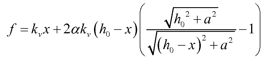
式 5)两边除以 L0kv无量纲化后可得 = x + la i-γ (6)

上式两边各除以位 可得 度的无量纲表达形式:
(7)

由上式可以得到, 当系统刚度 f最小 (等于零) 时, H ^/T^ 此时, 若确定了 初始倾角, 令上式等于零, 则可解出唯一的准零刚度的刚度比《。7 , 解得 a, 7
ezs~2(i-r) 并且, 该准-零刚度点的位置位于 = ^=VT ,即 = ^/1^ 处。
同理, 可以知道, 在系统的刚度比已知的情况下, 同样可以得出系统初始倾角的大小, 关系式如下:
2a
2a + l 同样的, 准-零刚度点的位置位于 c =
 。 在本实施例中,简化模型如图 5所示。拟定《 = 0.5,可得 jezs=0.5, = l- 2 =0.866处。 取小球质量为 4 KG, 重力加速度为 9.8N/kg, 则小球所受重力为 39.2N, 将值代入式 (6) 中, 可求得 。 = 45.26N, 假定弹簧长度3为 0.2m, 则可求得竖直弹簧刚度为 kv = 226.3N / ,则 斜弹簧为 113.15 N/mo
采用 ABAQUS依照设计参数进行仿真模拟, 设小球为刚体, 竖直弹簧刚度 226. 3N/m, 斜弹 簧刚度为 113. 15N/m。 弹簧长度为 0. 2m, 斜弹簧倾斜角为 60度。将集中荷载 100N施加在刚体参 考点上, 利用静力分析步计算得到力 -时间曲线, 位移 -时间曲线, 并与时间-力曲线合并可得 力 -位移曲线, 可以看到, 当荷载加至 39N时, 曲线斜率趋于 0, 意味着刚度接近于 0, 此刻弹 簧位移值为 0. 152m,荷载增至 40N时,小球位移值为 0. 207m,荷载增加 IN而位移值增加 0. 055m, 可以确定在位移为 0. 152~0. 207m的范围内, 系统刚度非常小, 并且解析解 = 0.173m, 也落于此区间内, 证明了数值模拟计算的正确性, 并且可以确定仅在重力作用下小球可处于 准-零刚度状态。 根据计算可得负刚度弹簧及正刚度弹簧的反力曲线, 通过其变化趋势可知, 当负刚度弹簧在 t=0. 39s的时刻反力迅速减小,而此时刻正刚度弹簧反力则迅速增大从而保持 小球静力平衡, 从而竖向位移在 0. 39s处呈跳跃式增长。 由此可以确定该结构可以应用于微动 台重力补偿结构之中。
。 在本实施例中,简化模型如图 5所示。拟定《 = 0.5,可得 jezs=0.5, = l- 2 =0.866处。 取小球质量为 4 KG, 重力加速度为 9.8N/kg, 则小球所受重力为 39.2N, 将值代入式 (6) 中, 可求得 。 = 45.26N, 假定弹簧长度3为 0.2m, 则可求得竖直弹簧刚度为 kv = 226.3N / ,则 斜弹簧为 113.15 N/mo
采用 ABAQUS依照设计参数进行仿真模拟, 设小球为刚体, 竖直弹簧刚度 226. 3N/m, 斜弹 簧刚度为 113. 15N/m。 弹簧长度为 0. 2m, 斜弹簧倾斜角为 60度。将集中荷载 100N施加在刚体参 考点上, 利用静力分析步计算得到力 -时间曲线, 位移 -时间曲线, 并与时间-力曲线合并可得 力 -位移曲线, 可以看到, 当荷载加至 39N时, 曲线斜率趋于 0, 意味着刚度接近于 0, 此刻弹 簧位移值为 0. 152m,荷载增至 40N时,小球位移值为 0. 207m,荷载增加 IN而位移值增加 0. 055m, 可以确定在位移为 0. 152~0. 207m的范围内, 系统刚度非常小, 并且解析解 = 0.173m, 也落于此区间内, 证明了数值模拟计算的正确性, 并且可以确定仅在重力作用下小球可处于 准-零刚度状态。 根据计算可得负刚度弹簧及正刚度弹簧的反力曲线, 通过其变化趋势可知, 当负刚度弹簧在 t=0. 39s的时刻反力迅速减小,而此时刻正刚度弹簧反力则迅速增大从而保持 小球静力平衡, 从而竖向位移在 0. 39s处呈跳跃式增长。 由此可以确定该结构可以应用于微动 台重力补偿结构之中。
Claims
1. 一种用于微动台重力补偿的负刚度系统, 其特征在于: 所述的负刚度系统包括至少三 组准-零刚度单元;所述的每一组准-零刚度单元由一对负刚度弹簧(2)与一个正刚度弹簧(3) 组合而成, 所述的一个正刚度弹簧 (3) 竖直布置, 所述的一对负刚度弹簧 (2) 倾斜并对称 布置在正刚度弹簧(3) 的两侧, 所述的负刚度弹簧 (2)和正刚度弹簧 (3) 的上端连接在一 起, 并与微动台动子 (1 )底面固定, 所述的负刚度弹簧(2)和所述的正刚度弹簧 (3) 的下 端分别连接在基座 (4) 上;
设稳定的准 -零刚度点的每一个负刚度弹簧和水平位置之间的初始夹角的锐角,即负刚度 弹簧的初始倾角^都对应着一个特定的准零刚度点的负弹簧与正弹簧刚度比,用《ezs 表示;
γ
aQZS ~ 2(\ - γ) 上述式中: a = k。lk。 为刚度比;
L。: 负刚度弹簧的原始长度;
L -. 负刚度弹簧变形后的长度;
7: 负刚度弹簧初始倾角的余弦值, 定义为 y = cose。 ;
a 负刚度弹簧在水平方向的投影长度, 定义为 a = L COs 0 ;
负刚度弹簧的刚度;
: 正刚度弹簧的刚度 。
2. 按照权利要求 1所述的一种用于微动台重力补偿的负刚度系统, 其特征在于: 采用三 组所述的准-零刚度单元的负刚度系统, 按照三角形布置; 采用四组所述的准-零刚度单元的 负刚度系统, 按照矩形来布置。
Priority Applications (1)
| Application Number | Priority Date | Filing Date | Title |
|---|---|---|---|
| US14/652,055 US9752643B2 (en) | 2012-12-12 | 2013-12-06 | Negative stiffness system for gravity compensation of micropositioner |
Applications Claiming Priority (2)
| Application Number | Priority Date | Filing Date | Title |
|---|---|---|---|
| CN2012105377861A CN103116249A (zh) | 2012-12-12 | 2012-12-12 | 一种用于微动台重力补偿的负刚度系统 |
| CN201210537786.1 | 2012-12-12 |
Publications (1)
| Publication Number | Publication Date |
|---|---|
| WO2014090115A1 true WO2014090115A1 (zh) | 2014-06-19 |
Family
ID=48414669
Family Applications (1)
| Application Number | Title | Priority Date | Filing Date |
|---|---|---|---|
| PCT/CN2013/088753 Ceased WO2014090115A1 (zh) | 2012-12-12 | 2013-12-06 | 一种用于微动台重力补偿的负刚度系统 |
Country Status (3)
| Country | Link |
|---|---|
| US (1) | US9752643B2 (zh) |
| CN (1) | CN103116249A (zh) |
| WO (1) | WO2014090115A1 (zh) |
Cited By (7)
| Publication number | Priority date | Publication date | Assignee | Title |
|---|---|---|---|---|
| CN111911576A (zh) * | 2020-09-09 | 2020-11-10 | 吉林大学 | 一种悬臂片弹簧准零刚度隔振器 |
| CN112747061A (zh) * | 2020-12-29 | 2021-05-04 | 西安交通大学 | 一种基于双稳态曲梁的隔振结构 |
| CN115789149A (zh) * | 2022-11-17 | 2023-03-14 | 北京无线电测量研究所 | 一种新型准零刚度隔振器及设计方法 |
| CN115899133A (zh) * | 2022-10-20 | 2023-04-04 | 天津电气科学研究院有限公司 | 一种用于大负载微振动的负刚度弹簧结构 |
| CN116292750A (zh) * | 2023-04-03 | 2023-06-23 | 上海大学 | 准零刚度车载隔振器 |
| CN118705312A (zh) * | 2024-07-08 | 2024-09-27 | 武汉理工大学 | 一种二维准零刚度点阵装置及其设计方法 |
| CN119467593A (zh) * | 2024-12-11 | 2025-02-18 | 广东工业大学 | 高静低动刚度特性的纳米云台 |
Families Citing this family (22)
| Publication number | Priority date | Publication date | Assignee | Title |
|---|---|---|---|---|
| CN103116249A (zh) | 2012-12-12 | 2013-05-22 | 清华大学 | 一种用于微动台重力补偿的负刚度系统 |
| BR112017006186B8 (pt) * | 2014-10-17 | 2023-02-14 | Nuovo Pignone Srl | Sistema de montagem para apoiar maquinaria rotativa e método de montagem de uma armação de base |
| CN105587974A (zh) * | 2014-10-21 | 2016-05-18 | 无锡利博科技有限公司 | 机床的斜支撑式张紧支撑结构 |
| CN105583682A (zh) * | 2014-10-21 | 2016-05-18 | 无锡利博科技有限公司 | 便调式斜弹簧支撑的支撑机构 |
| WO2017043230A1 (ja) * | 2015-09-07 | 2017-03-16 | 国立大学法人埼玉大学 | 弾性機構 |
| WO2017177231A1 (en) * | 2016-04-08 | 2017-10-12 | Ohio University | Passive variable negative stiffness device and methods of use thereof |
| CN105889385B (zh) * | 2016-06-14 | 2017-09-12 | 西安交通大学 | 一种压缩弹簧式六自由度准零刚度隔振器及其设计方法 |
| IT201600127545A1 (it) * | 2016-12-16 | 2018-06-16 | Nuovo Pignone Tecnologie Srl | Sistema di montaggio per macchine rotanti |
| CN106742091B (zh) * | 2016-12-27 | 2018-07-06 | 哈尔滨工业大学 | 一种具有零频隔振特征的零重力或微重力悬浮方法及装置 |
| CN108757803A (zh) * | 2018-07-13 | 2018-11-06 | 浙江睿思自动化技术有限公司 | 六自由度准零刚度隔振装置 |
| CN109185377A (zh) * | 2018-11-07 | 2019-01-11 | 苗改燕 | 一种精密减振组件及由其构成的减振平台 |
| CN110081264B (zh) * | 2019-05-08 | 2021-02-09 | 中国船舶科学研究中心(中国船舶重工集团公司第七0二研究所) | 基于准零刚度的管路支撑隔振装置 |
| CN111853126B (zh) * | 2020-07-24 | 2021-08-27 | 郑州轻工业大学 | 基于三对斜弹簧的高线性共振频率的准零刚隔振装置 |
| CN112527027B (zh) * | 2020-12-18 | 2025-03-07 | 湖南大学 | 一种被动超低频角振动控制系统及其振动控制方法 |
| CN113586660B (zh) * | 2021-08-12 | 2022-05-03 | 重庆大学 | 一种模块化准零刚度隔振结构 |
| CN113700795A (zh) * | 2021-09-03 | 2021-11-26 | 山东汽车制造有限公司 | 一种具有准零度刚度特性的轻卡驾驶室隔振方法及装置 |
| CN114061881B (zh) * | 2021-11-30 | 2022-09-16 | 华南农业大学 | 一种准零刚度振动试验台 |
| CN114294322B (zh) * | 2021-12-30 | 2022-10-04 | 哈尔滨工业大学 | 一种基于被动补偿结构的准零刚度柔性导向机构 |
| CN114278703B (zh) * | 2021-12-30 | 2024-03-15 | 哈尔滨工程大学 | 一种双几何非线性结构集成的低频准零刚度隔振器 |
| CN116792460B (zh) * | 2022-03-15 | 2025-11-28 | 安徽美芝制冷设备有限公司 | 准零刚度脚垫、压缩机及制冷制热设备 |
| CN117329268A (zh) * | 2023-10-20 | 2024-01-02 | 天津电气科学研究院有限公司 | 一种降低负刚度弹簧刚度变化的负刚度并联结构 |
| CN120406055B (zh) * | 2025-05-20 | 2025-12-09 | 同济大学 | 重力补偿装置、微动台及半导体设备 |
Citations (7)
| Publication number | Priority date | Publication date | Assignee | Title |
|---|---|---|---|---|
| CN85109107A (zh) * | 1985-11-01 | 1987-05-06 | 杭州电子工业学院 | 正负刚度弹性元件并联的减振装置 |
| JPH08166043A (ja) * | 1994-10-11 | 1996-06-25 | Nikon Corp | 防振装置 |
| CN202132428U (zh) * | 2011-06-29 | 2012-02-01 | 湖南大学 | 具有准零刚度的非线性磁力隔振器 |
| CN102410337A (zh) * | 2011-10-25 | 2012-04-11 | 清华大学 | 一种基于负刚度原理的永磁低频多自由度隔振度机构 |
| CN102734377A (zh) * | 2011-03-31 | 2012-10-17 | 上海微电子装备有限公司 | 负刚度装置及应用所述负刚度装置的减振系统 |
| CN202520846U (zh) * | 2012-03-26 | 2012-11-07 | 湖南大学 | 一种针对基础激励的低频隔振器 |
| CN103116249A (zh) * | 2012-12-12 | 2013-05-22 | 清华大学 | 一种用于微动台重力补偿的负刚度系统 |
Family Cites Families (3)
| Publication number | Priority date | Publication date | Assignee | Title |
|---|---|---|---|---|
| DE19809545C1 (de) * | 1998-03-05 | 1999-05-12 | Deutsch Zentr Luft & Raumfahrt | Dynamisches System mit einem Aktuator zur dynamischen Anregung einer Struktur und Verfahren zur Vergrößerung der dabei erzielbaren dynamischen Verformung der Struktur |
| JP4157393B2 (ja) * | 2003-02-18 | 2008-10-01 | 毅 水野 | 除振装置 |
| CN102506110B (zh) * | 2011-10-25 | 2013-10-30 | 清华大学 | 一种基于负刚度原理的永磁低频单自由度隔振机构 |
-
2012
- 2012-12-12 CN CN2012105377861A patent/CN103116249A/zh active Pending
-
2013
- 2013-12-06 US US14/652,055 patent/US9752643B2/en active Active
- 2013-12-06 WO PCT/CN2013/088753 patent/WO2014090115A1/zh not_active Ceased
Patent Citations (7)
| Publication number | Priority date | Publication date | Assignee | Title |
|---|---|---|---|---|
| CN85109107A (zh) * | 1985-11-01 | 1987-05-06 | 杭州电子工业学院 | 正负刚度弹性元件并联的减振装置 |
| JPH08166043A (ja) * | 1994-10-11 | 1996-06-25 | Nikon Corp | 防振装置 |
| CN102734377A (zh) * | 2011-03-31 | 2012-10-17 | 上海微电子装备有限公司 | 负刚度装置及应用所述负刚度装置的减振系统 |
| CN202132428U (zh) * | 2011-06-29 | 2012-02-01 | 湖南大学 | 具有准零刚度的非线性磁力隔振器 |
| CN102410337A (zh) * | 2011-10-25 | 2012-04-11 | 清华大学 | 一种基于负刚度原理的永磁低频多自由度隔振度机构 |
| CN202520846U (zh) * | 2012-03-26 | 2012-11-07 | 湖南大学 | 一种针对基础激励的低频隔振器 |
| CN103116249A (zh) * | 2012-12-12 | 2013-05-22 | 清华大学 | 一种用于微动台重力补偿的负刚度系统 |
Cited By (7)
| Publication number | Priority date | Publication date | Assignee | Title |
|---|---|---|---|---|
| CN111911576A (zh) * | 2020-09-09 | 2020-11-10 | 吉林大学 | 一种悬臂片弹簧准零刚度隔振器 |
| CN112747061A (zh) * | 2020-12-29 | 2021-05-04 | 西安交通大学 | 一种基于双稳态曲梁的隔振结构 |
| CN115899133A (zh) * | 2022-10-20 | 2023-04-04 | 天津电气科学研究院有限公司 | 一种用于大负载微振动的负刚度弹簧结构 |
| CN115789149A (zh) * | 2022-11-17 | 2023-03-14 | 北京无线电测量研究所 | 一种新型准零刚度隔振器及设计方法 |
| CN116292750A (zh) * | 2023-04-03 | 2023-06-23 | 上海大学 | 准零刚度车载隔振器 |
| CN118705312A (zh) * | 2024-07-08 | 2024-09-27 | 武汉理工大学 | 一种二维准零刚度点阵装置及其设计方法 |
| CN119467593A (zh) * | 2024-12-11 | 2025-02-18 | 广东工业大学 | 高静低动刚度特性的纳米云台 |
Also Published As
| Publication number | Publication date |
|---|---|
| US9752643B2 (en) | 2017-09-05 |
| US20150369331A1 (en) | 2015-12-24 |
| CN103116249A (zh) | 2013-05-22 |
Similar Documents
| Publication | Publication Date | Title |
|---|---|---|
| WO2014090115A1 (zh) | 一种用于微动台重力补偿的负刚度系统 | |
| CN103438142B (zh) | 一种六自由度主动隔振装置 | |
| CN104678711B (zh) | 运动台反力抵消装置 | |
| CN102189413A (zh) | 一种超精密工作台 | |
| CN105889385B (zh) | 一种压缩弹簧式六自由度准零刚度隔振器及其设计方法 | |
| JP5206709B2 (ja) | 可動体を備えている装置 | |
| CN103226295A (zh) | 一种光刻机硅片台微动工作台 | |
| WO2019019718A1 (zh) | 集传感单元和约束元件于一体的二维快速偏转台及方法 | |
| TWI616725B (zh) | 位置測量設備,圖案轉移設備及製造一裝置的方法 | |
| CN102927183A (zh) | 一种低频两自由度水平隔振机构 | |
| CN202317689U (zh) | 一种带气浮支承和电磁驱动的超精密工作台 | |
| CN112984044B (zh) | 精密设备搭载用除振装置 | |
| US20090241719A1 (en) | Six-degree-of-freedom precision positioning system | |
| Ahn | Eddy current damper type reaction force compensation mechanism for linear motor motion stage | |
| CN105915105B (zh) | 一种惯性压电驱动器 | |
| Lei et al. | Modeling and analysis of a 3-DOF Lorentz-force-driven planar motion stage for nanopositioning | |
| CN203275876U (zh) | 一种光刻机硅片台微动工作台 | |
| CN106059377B (zh) | 一种步进压电驱动器 | |
| JP4997511B2 (ja) | 振動絶縁装置 | |
| CN106871887B (zh) | 振动模组以及陀螺仪 | |
| CN205666764U (zh) | 一种步进压电驱动器 | |
| JP2014177152A (ja) | 移動装置及びプログラム | |
| CN203951388U (zh) | 一种六自由度磁悬浮运动台 | |
| Jun et al. | Development of a novel uniaxial force sensor with two-stage force resolutions | |
| CN105526306A (zh) | 一种宽频带柔性浮筏隔振系统及其设计方法 |
Legal Events
| Date | Code | Title | Description |
|---|---|---|---|
| 121 | Ep: the epo has been informed by wipo that ep was designated in this application |
Ref document number: 13862634 Country of ref document: EP Kind code of ref document: A1 |
|
| NENP | Non-entry into the national phase |
Ref country code: DE |
|
| WWE | Wipo information: entry into national phase |
Ref document number: 14652055 Country of ref document: US |
|
| 122 | Ep: pct application non-entry in european phase |
Ref document number: 13862634 Country of ref document: EP Kind code of ref document: A1 |