WO2014084017A1 - リークテスト方法 - Google Patents
リークテスト方法 Download PDFInfo
- Publication number
- WO2014084017A1 WO2014084017A1 PCT/JP2013/080129 JP2013080129W WO2014084017A1 WO 2014084017 A1 WO2014084017 A1 WO 2014084017A1 JP 2013080129 W JP2013080129 W JP 2013080129W WO 2014084017 A1 WO2014084017 A1 WO 2014084017A1
- Authority
- WO
- WIPO (PCT)
- Prior art keywords
- communication path
- space
- amount
- leakage
- leakage amount
- Prior art date
- Legal status (The legal status is an assumption and is not a legal conclusion. Google has not performed a legal analysis and makes no representation as to the accuracy of the status listed.)
- Ceased
Links
Images




Classifications
-
- G—PHYSICS
- G01—MEASURING; TESTING
- G01M—TESTING STATIC OR DYNAMIC BALANCE OF MACHINES OR STRUCTURES; TESTING OF STRUCTURES OR APPARATUS, NOT OTHERWISE PROVIDED FOR
- G01M3/00—Investigating fluid-tightness of structures
- G01M3/02—Investigating fluid-tightness of structures by using fluid or vacuum
- G01M3/26—Investigating fluid-tightness of structures by using fluid or vacuum by measuring rate of loss or gain of fluid, e.g. by pressure-responsive devices, by flow detectors
-
- G—PHYSICS
- G01—MEASURING; TESTING
- G01M—TESTING STATIC OR DYNAMIC BALANCE OF MACHINES OR STRUCTURES; TESTING OF STRUCTURES OR APPARATUS, NOT OTHERWISE PROVIDED FOR
- G01M3/00—Investigating fluid-tightness of structures
- G01M3/02—Investigating fluid-tightness of structures by using fluid or vacuum
- G01M3/025—Details with respect to the testing of engines or engine parts
-
- G—PHYSICS
- G01—MEASURING; TESTING
- G01M—TESTING STATIC OR DYNAMIC BALANCE OF MACHINES OR STRUCTURES; TESTING OF STRUCTURES OR APPARATUS, NOT OTHERWISE PROVIDED FOR
- G01M3/00—Investigating fluid-tightness of structures
- G01M3/02—Investigating fluid-tightness of structures by using fluid or vacuum
- G01M3/26—Investigating fluid-tightness of structures by using fluid or vacuum by measuring rate of loss or gain of fluid, e.g. by pressure-responsive devices, by flow detectors
- G01M3/32—Investigating fluid-tightness of structures by using fluid or vacuum by measuring rate of loss or gain of fluid, e.g. by pressure-responsive devices, by flow detectors for containers, e.g. radiators
- G01M3/3236—Investigating fluid-tightness of structures by using fluid or vacuum by measuring rate of loss or gain of fluid, e.g. by pressure-responsive devices, by flow detectors for containers, e.g. radiators by monitoring the interior space of the containers
- G01M3/3263—Investigating fluid-tightness of structures by using fluid or vacuum by measuring rate of loss or gain of fluid, e.g. by pressure-responsive devices, by flow detectors for containers, e.g. radiators by monitoring the interior space of the containers using a differential pressure detector
Definitions
- the present invention relates to a technique of a leak test method, and more specifically, in a work having three divided gaps, the amount of leakage in each gap is quantitatively determined, and whether or not there is a leak in each gap accurately.
- the present invention relates to a technique for determining
- a cylinder block that is a member constituting an engine includes a space (hereinafter, referred to as a first space) including a crankcase in which a crankshaft is stored, a cylinder bore, and the like, and a space (hereinafter, referred to as a cooling water). And a space through which engine oil flows (hereinafter referred to as a third space).
- circulates these each space formed in a cylinder block must not leak (leak) to other space.
- the casting hole forms a path that communicates each space, and leakage may occur between each space and the outside.
- a substitute characteristic value of the channel resistance is calculated from the flow rate change and pressure change behavior during pressure filling.
- the substitute characteristic value is evaluated to determine the presence or absence of leakage.
- Patent Document 1 it has been impossible to accurately determine the amount of leakage by separating how much leakage has occurred from each space to which space. For this reason, even if there is a minute leak that does not pose a problem when considering the pressure and pressure difference acting on each space, the workpiece is judged as a defective product, and there is no problem in actual use. There was a case that was discarded.
- the present invention has been made in view of such a current problem, and in a work having a space that is a space defined by three sections, the amount of leakage from each space is separated and grasped, and a good or defective product is accurately obtained.
- An object of the present invention is to provide a leak test method capable of determining a non-defective product.
- the first invention includes a first space, a second space, and a third space, which are divided three gaps, and the first outer space communicates with the first space.
- a work leak test method that may comprise: a first gas that is press-fitted into the first space at a predetermined pressure, and the first internal communication path and the third internal communication path.
- a first total leakage amount that is a total amount of the gas leaking from the path and the first external communication path; The total amount of the gas leaked from the first internal communication path, the second internal communication path, and the second external communication path after the gas is pressed into the second space at a predetermined pressure.
- a second step of acquiring a second total leakage amount, and injecting a gas into the third space at a predetermined pressure, the second internal communication path, the third internal communication path, and the third A third step of obtaining a third total leakage amount that is a total amount of the gas leaking from the external communication path, and gas at a predetermined pressure in the first space, the second space, and the third space;
- a sixth step of acquiring a sixth total leakage amount that is a total amount of the gas that leaks, and a predetermined pressure of the gas with respect to the workpiece based on the acquired first to sixth total leakage amounts In the case of press-fitting in, a first leakage amount that is a leakage amount from the first external communication path, a second leakage amount that is a leakage amount from the second external communication path, and the third The third leakage amount, which is the leakage amount from the external communication path, and the first internal communication path A fourth leakage amount that is a leakage amount, a fifth leakage amount that is a leakage amount from the second internal communication path, and a sixth leakage amount that is a leakage amount from the third internal communication path. , And a step of determining the quality of the workpiece based on the calculated first to sixth leakage amounts.
- a second invention includes a first space, a second space, and a third space, which are divided three gap portions, and a first external communication path that communicates the first space with the outside.
- a second external communication path that communicates the second space with the outside, a third external communication path that communicates the third space with the outside, the first space, and the second space.
- a first internal communication path that communicates, a second internal communication path that communicates the second space and the third space, and a third interior that communicates the third space and the first space.
- a work leakage test method that may comprise a communication path, wherein a gas is pressed into the first space at a predetermined pressure, and the first internal communication path and the third internal communication path are A first step of obtaining a first total leakage amount which is a total amount of the gas leaking from the first external communication path; A second gas which is a total amount of the gas leaked from the first internal communication path, the second internal communication path, and the second external communication path by injecting gas into the second space at a predetermined pressure. A second step of acquiring a total leakage amount, and a gas is injected into the third space at a predetermined pressure, and the second internal communication path, the third internal communication path, and the third external communication path.
- the leak test is terminated.
- the first determination process is further performed. Space, the second space and the third space.
- a fourth total leakage amount that is a total amount of the gas that leaks from the first external communication path, the second external communication path, and the third external communication path.
- a fourth step injecting gas into the first space and the third space at a predetermined pressure, the first external communication path, the third external communication path, and the first internal communication path;
- a fifth step of obtaining a fifth total leakage amount which is a total amount of the gas leaking from the second internal communication path, and injecting gas into the first space and the second space at a predetermined pressure;
- obtaining a sixth total leakage amount that is a total amount of the gas leaking from the first external communication path, the second external communication path, the second internal communication path, and the third internal communication path.
- a first leakage amount that is a leakage amount from the first external communication path and a second leakage amount that is a leakage amount from the second external communication path A leakage amount, a third leakage amount that is a leakage amount from the third external communication path, a fourth leakage amount that is a leakage amount from the first internal communication path, and the second internal communication
- the first aspect of the present invention it is possible to separate the leakage amount between the partitioned spaces and the leakage amount from each space to the outside and accurately grasp the leakage amount. As a result, it is possible to improve the accuracy of determination of non-defective / defective products by the leak test, and it is possible to reduce the number of workpieces that are determined to be defective even though they are non-defective.
- FIG. 5 is a schematic diagram showing an implementation status of the leak test method according to the first embodiment of the present invention, (a) a schematic diagram showing an acquisition status of the first total leak amount T 1 , and (b) a second total leak amount T 2.
- FIG. 5 is a schematic diagram showing an implementation status of the leak test method according to the first embodiment of the present invention, (a) a schematic diagram showing an acquisition status of the third total leak amount T 3 , and (b) a fourth total leak amount T 4.
- FIG. 6 is a schematic diagram showing an implementation status of a leak test method according to the first embodiment of the present invention, (a) a schematic diagram showing an acquisition status of a fifth total leak amount T 5 , and (b) a sixth total leak amount T 6.
- the flowchart which shows the flow of the leak test method (when changing test
- the inspection apparatus 1 used in the leak test method according to an embodiment of the present invention causes leakage (leakage) in three gap portions formed in the workpiece 10 that is an inspection object. It is an apparatus for inspecting the presence / absence of a path that communicates with each other or communicates between each cavity and the outside, and is configured to include a leak tester 2, an arithmetic device 4, and the like.
- the leak tester 2 is a differential pressure detection type leak tester and includes a master 3.
- the master 3 is a container that is guaranteed to have no leakage for generating the reference pressure, and the leak tester 2 detects the pressure difference in the master 3 and the pressure in the work 10 by detecting the pressure in the work 10. It is possible to detect the presence or absence of leakage, the amount of leakage from the work 10 at the pressure, and the like.
- the leak tester 2 shown in the present embodiment is configured to employ air as a fluid used for detecting the differential pressure, and the leak tester 2 is connected to an air pipe 6 serving as an air supply source via a pressure regulating valve 5. It is assumed to be configured. In the present embodiment, a case where a differential pressure type leak tester is employed as a leak tester for detecting the presence or absence of leakage in each space is illustrated, but the leak tester constituting the inspection apparatus according to the present invention The configuration is not limited to this.
- the specification of the leak tester used in the leak test method according to the present invention is not limited to this, for example, helium or A configuration using a leak tester using other inert gas or the like may be used.
- the arithmetic device 4 is a device for calculating the presence / absence of leakage in each space and the amount of leakage from each space by calculation from the measurement result of the leak tester 2, and is connected to the leak tester 2.
- arithmetic unit 4 a general-purpose personal computer that includes arithmetic means (CPU), storage means (ROM or RAM), external storage means (HDD), etc., and in which a predetermined arithmetic program is installed is used. it can.
- FIG. 1 schematically represents a cylinder block for constituting the engine.
- the workpiece 10 illustrated here includes a series of spaces (hereinafter referred to as C / C) formed by a crankcase, a cylinder bore, and a chain case as a first space, and a circulation path of engine oil as a second space ( Hereinafter, it is referred to as O / H) and a cooling water circulation path (hereinafter referred to as W / J) as a third space.
- C / C a series of spaces
- O / H a circulation path of engine oil
- W / J cooling water circulation path
- the leakage amount from the first path R 1 defines an outer leak amount Q 1
- outer leak amount Q 2 defines the amount of leakage from the third path R 3 and the outer leak amount Q 3.
- the leakage amount from the fourth path R 4 is defined as the internal leakage amount q 1
- the leakage amount from the fifth path R 5 is defined as the internal leakage amount q 2.
- an opening other than a connection port for supplying a gas necessary for the leak test is provided with a predetermined sealing jig (see FIG. 2). It seals using (not shown) (STEP-101).
- the work 10 is prepared so that the gas used for the leak test does not leak out from the opening portion closed with the sealing jig.
- the pipe 7 connected to the leak tester 2 is branched into three systems, and a valve is provided in each pipe 7 of each system after branching.
- a pipe 7 of a system including a first valve (hereinafter referred to as VL1) is connected to W / J, and a second valve (hereinafter referred to as VL2) is connected to C / C.
- VL1 a first valve
- VL2 a second valve
- VL3 the piping 7 of the system provided with the third valve
- the total leakage amount T 1 measured at this time is an amount expressed by the following Equation 1, and an external leakage amount Q 1 leaking to the outside from the C / C through the route R 1 and the C / C through the route R 4. This is the sum of the amount of internal leakage q 1 leaking from C to O / H and the amount of internal leakage q 3 leaking from C / C to W / J through the route R 6 .
- the total leak rate T 2 to be measured at this time is an amount represented by Equation 2 below, the outer leak amount Q 2 to which leaks to the outside from O / H over path R 2, through a path R 4 O / This is the sum of the amount of internal leakage q 1 leaking from H to C / C and the amount of internal leakage q 2 leaking from O / H to W / J through the route R 5 .
- the leakage amount Q 3 leaks to the outside through the path R 3 from the W / J and the W / J through the path R 5. This is the sum of the amount of internal leakage q 2 leaking from J to O / H and the amount of internal leakage q 3 leaking from W / J to C / C through the path R 6 .
- the non-defective product or defective product of the workpiece 10 is determined based on the total leakage amounts T 1 to T 3 measured so far by the arithmetic unit 4. (STEP-108).
- the leakage test is ended here.
- the leak test is further continued.
- the total leakage amount T 4 to be measured at this time is an amount represented by Equation 4 below, the outer leak amount Q 1 which leaks to the outside of the workpiece 10 through the path R 1 from C / C, O / H It has an outer leak amount Q 2 to which leaks to the outside of the workpiece 10 through the route R 2, and the amount obtained by summing the external leak amount Q 3 which leaks to the outside of the workpiece 10 through the path R 3 from W / J from.
- the total leakage amount T 5 to be measured at this time is an amount represented by Equation 5 below, the outer leak amount Q 1 which leaks to the outside of the workpiece 10 through the path R 1 from C / C, W / J
- the amount of external leakage Q 3 leaking to the outside of the workpiece 10 through the route R 3 the amount of internal leakage q 1 leaking from C / C to O / H through the route R 4 , and W / J to O / through the route R 5. It has a quantity obtained by summing the amount of leakage q 2 inner leak to H.
- the total leakage amount T 6 to be measured at this time is an amount represented by Equation 6 below, the outer leak amount Q 1 which leaks to the outside of the workpiece 10 through the path R 1 from C / C, O / H
- the amount of outside leakage Q 2 leaking to the outside of the workpiece 10 through the route R 2 the amount of internal leakage q 2 leaking from O / H to W / J through the route R 5 , and C / C to W / through the route R 6 This is the sum of the amount of internal leakage q 3 leaking to J.
- the following separation is performed by the arithmetic unit 4 based on the total leak amounts T 1 to T 6 measured so far. Calculation based on the algorithm is performed to calculate the respective leakage amounts Q 1 , Q 2 , Q 3 , q 1 , q 2 , q 3 (STEP-115).
- the arithmetic unit 4 is previously introduced separation algorithm which will be described later, by the arithmetic unit 4, Leak Tester second measurements (i.e., the total leak rate T 1 ⁇ T 6) on the basis of, the amount of leakage (Q 1 , Q 2 , Q 3 , q 1 , q 2 , q 3 ) are calculated separately.
- the total sum of the measured total leakage amounts T 1 to T 3 is defined as S Qq , as shown in Equation 7 below. Then, the total sum S Qq of each total leakage amount T 1 to T 3 is calculated.
- the total amount of internal leaks (ie, q 1 + q 2 + q 3 ) is defined as S q as shown in the following Equation 8.
- the calculation device 4 calculates the total amount S q of the internal leakage amount.
- the internal leakage amount q 3 from the route R 6 is calculated by the arithmetic device 4 based on the following formula 9.
- the internal leak amount q 1 from the route R 4 is calculated by the arithmetic device 4 based on the following formula 10.
- the internal leakage amount q 2 from the route R 5 is calculated by the arithmetic device 4 based on the following formula 11.
- the computation device 4 calculates an outside leakage amount Q 1 from the route R 1 based on the following formula 12.
- the computation device 4 calculates the amount of outside leakage Q 2 from the route R 2 based on the following Equation 13.
- the computing device 4 calculates an outside leakage amount Q 3 from the route R 3 based on the following formula 14.
- each of the leak amounts Q 1 , Q 2 , Q 3 , q 1 , q 2 , the q 3 can be quantitatively calculated (STEP-116). Then, based on the calculated leakage amounts Q 1 , Q 2 , Q 3 , q 1 , q 2 , q 3 , the arithmetic device 4 determines whether the workpiece 10 is a good product or a defective product (STEP- 117).
- the spaces C / C, O / H, and W / J in the workpiece 10 have different fluids flowing through them, and also have different internal pressures in use.
- internal pressures in use are O / H, W / J, and C / C in descending order of pressure.
- each leak amount Q 1 , Q 2 , Q 3 , q 1 , q 2 , q 3 in the workpiece 10 can be quantitatively calculated.
- the first space (C / C) and the second space (O / H), which are the three divided voids, and the third space It includes a space (W / J), and a path R 1 first serving one external communication path communicating the C / C and the outside, and the second external communication path serving path R 2 which communicates the O / H and external , Path R 3 as a third external communication path for communicating W / J and the outside, path R 4 as a first internal communication path for communicating C / C and O / H, and O / H and W / J
- a leak test method for a workpiece 10 that may include a path R 5 that is a second internal communication path that communicates with the C / C and a path R 6 that is a third internal communication path that communicates W / J and C / C.
- a third step of obtaining (sTEP-107), press-fitting the gas at a predetermined pressure P to the C / C and O / H and W / J, leakage from the route R 1 and a route R 2 and the route R 3 leaving the total amount of the gas (i.e., Q 1 + Q 2 + Q 3) is a fourth step of obtaining a fourth total leakage amount T 4 (ST And P-110), press-fitting the gas at a predetermined pressure P to the C / C and W / J, the total amount of the gas leaking from the route R 1 and a route R 3 and the route R 4 and route R 5 (i.e., Q
- a fifth total leak amount T 6 is obtained which is a total amount of the gas leaking from the route R 1
- the first leakage which is the leakage amount from the path R 1 when the gas is pressed into the workpiece 10 at a predetermined pressure P
- Calculating a fifth leakage amount (inner leakage amount q 2 ) that is the amount of leakage and a sixth leakage amount (inner leakage amount q 3 ) that is a leakage amount from the path R 6 (STEP-116);
- the step of determining the quality of the workpiece 10 based on the calculated first to sixth leakage amounts (that is, the respective leakage amounts Q 1 , Q 2 , Q
- the amounts of internal leakage q 1 , q 2 , q 3 between the partitioned spaces (C / C, O / H, W / J) and the spaces (C / C, O / H, W / J) from each of the outside leakage amounts Q 1 , Q 2 , Q 3 can be separated and the leakage amount can be accurately grasped.
- the second step (STEP-105), and the third step (STEP-107) are performed.
- the first determination step (STEP-108) for determining the quality of the workpiece 10 is performed based on the acquired first to third total leakage amounts T 1 to T 3 to obtain the first determination.
- step (STEP-108) when the workpiece 10 is determined to be a non-defective product, the leak test is terminated, and when the workpiece 10 is not determined to be a non-defective product, the fourth step (STEP-110) and the fifth step (STEP-108) STEP-112) and the sixth step (STEP-114) are carried out, and a predetermined pressure is applied to the workpiece 10 based on the acquired first to sixth total leakage amounts T 1 to T 6.
- each leakage amount of the sixth from the first Q 1, Q 2, Q 3 , q 1, q 2, q 3 and step of calculating (STEP-116) each of the leakage quantity Q 1 is calculated, Q 2,
- a second determination step (STEP-117) for determining the quality of the workpiece 10 based on Q 3 , q 1 , q 2 , q 3 is performed.
- the leak test method according to the first embodiment of the present invention is applied to suppress the time required for the leak test as it becomes possible to appropriately determine whether or not there is a leak. can do.
- each space (C / C, O / H, W / J) provided in the workpiece 10 shown in the present embodiment the fluid flowing inside is different, and the internal pressure in the use state is also different. Is different. For this reason, it is desirable to give each space (C / C, O / H, W / J) a test pressure corresponding to the internal pressure in the state of use. Therefore, in the second embodiment of the present invention described below, a leak test method in the case where different test pressures are applied to each space (C / C, O / H, W / J) will be described. .
- the leak test method according to the second embodiment can be realized using the same inspection apparatus 1 as the leak test method according to the first embodiment of the present invention described above. Moreover, the workpiece
- an opening other than a connection port for supplying a gas necessary for the leak test is provided with a predetermined sealing jig (FIG. 6). It seals using (not shown) (STEP-201).
- the work 10 is prepared so that the gas for leak test does not leak from the opening portion closed with the sealing jig. Then, the workpiece 10 is connected to the leak tester 2.
- the non-defective product or defective product of the workpiece 10 is determined based on the total leakage amounts T 1 to T 3 measured so far by the arithmetic unit 4. (STEP-208).
- the leakage test is ended here.
- the leak test is further continued.
- the total leakage amount T 4 to be measured at this time is an amount that is expressed by Equation 4 described above.
- the predetermined pressure P 4 at this time, each space (C / C, O / H , W / J) of, it is desirable to pressure corresponding to the operating pressure in the most used pressure is high space, the In the case of the embodiment, the pressure P 4 is set based on the use pressure of O / H.
- the leak test method according to the second embodiment of the present invention as shown in FIG. 6 and FIG. 5A, only VL3 is “closed” and VL1 and VL2 are “open” (STEP- 211).
- gas is supplied at a predetermined pressure P 5 in the C / C and W / J, the leakage tester 2 to measure the total leakage amount T 5 (STEP-212).
- information of the total leak rate T 5 measured this time is sent to the arithmetic unit 4 and stored in the arithmetic unit 4.
- the total leakage amount T 5 to be measured at this time is an amount that is expressed by Equation 5 described above.
- the predetermined pressure P 5 at this time is preferably a pressure corresponding to the use pressure in a space where the use pressure is high, among C / C and W / J. to set the pressure P 5 relative to the working pressure of J.
- the leak test method according to the second embodiment of the present invention as shown in FIGS. 6 and 5B, only VL1 is “closed” and VL2 and VL3 are “open” (STEP- 213).
- gas is supplied at a predetermined pressure P 6 in the C / C and O / H, due to a leakage tester 2 to measure the total leakage amount T 6 (STEP-214).
- the information on the total leakage amount T 6 measured at this time is sent to the calculation device 4 and stored in the calculation device 4.
- the predetermined pressure P 6 at this time is preferably a pressure corresponding to a use pressure in a space where the use pressure is high, of C / C and O / H. to set the pressure P 6 relative to the working pressure of the H.
- the total leak amounts T 1 to T 6 measured so far by the arithmetic unit 4 are used as the representative test pressure P 0.
- the total amount of leakage at (STEP-215).
- the calculation device 4 performs an operation based on the following separation algorithm to obtain each leakage amount Q 1 , Q 2 , Q 3 , q 1 , q 2 , q 3 are calculated (STEP-216).
- the representative inspection pressure P 0 at this time is preferably a pressure corresponding to the working pressure in the space having the highest working pressure among the spaces (C / C, O / H, W / J).
- the representative inspection pressure P 0 is set based on the use pressure of O / H.
- the separation algorithm in the leak test method according to the second embodiment of the present invention is the same as the separation algorithm in the leak test method according to the first embodiment of the present invention, and based on Equations 7 to 14 described above,
- the leakage amount Q 1 , Q 2 , Q 3 , q 1 , q 2 , q 3 is quantitatively calculated by the arithmetic device 4 (STEP-217). Then, based on the calculated leakage amounts Q 1 , Q 2 , Q 3 , q 1 , q 2 , q 3 , the arithmetic device 4 determines whether the workpiece 10 is a good product or a defective product (STEP- 218).
- the amount of leakage Q 1 , Q 2 , Q 3 , q 1 , q 2 , q in the workpiece 10 is considered in consideration of the pressure in the use state. 3 can be calculated quantitatively, and a non-defective product and a defective product can be determined more appropriately.
- the present invention can be widely applied not only to a work constituting an engine represented by a cylinder block, a cylinder head, etc., but also to a work having a gap section divided into three. If applied, it is possible to easily and accurately perform a leak test on a workpiece having four or more gaps.
Landscapes
- Physics & Mathematics (AREA)
- General Physics & Mathematics (AREA)
- Examining Or Testing Airtightness (AREA)
Abstract
【課題】三つの区画された空隙部たる空間を有するワークにおいて、各空間からの漏れ量を分離して把握し、精度よく良品あるいは不良品の判定を行うことができるリークテスト方法を提供する。 【解決手段】各総漏れ量T1~T6を取得する各工程(STEP-103、105、107、110、112、114)と、取得した各総漏れ量T1~T6に基づいて、ワーク10に対して気体を所定の圧力Pで圧入した場合における、経路R1からの漏れ量である第一の漏れ量(外漏れ量Q1)と、経路R2からの漏れ量である第二の漏れ量(外漏れ量Q2)と、経路R3からの漏れ量である第三の漏れ量(外漏れ量Q3)と、経路R4からの漏れ量である第四の漏れ量(内漏れ量q1)と、経路R5からの漏れ量である第五の漏れ量(内漏れ量q2)と、経路R6からの漏れ量である第六の漏れ量(内漏れ量q3)と、を算出する工程(STEP-116)を備えるリークテスト方法。
Description
本発明は、リークテスト方法の技術に関し、より詳しくは、三つに区画された空隙部を有するワークにおいて、各空隙部における漏れ量を定量的に求めて、精度よく各空隙部における漏れの有無を判定するための技術に関する。
例えば、エンジンを構成する部材であるシリンダブロックには、クランクシャフトが格納されるクランクケース、およびシリンダボア等からなる空間(以下、第一の空間と呼ぶ)と、冷却水が流通する空間(以下、第二の空間と呼ぶ)と、エンジンオイルが流通する空間(以下、第三の空間と呼ぶ)が形成されている。
そして、エンジンの機能を確保するためには、シリンダブロックに形成されるこれらの各空間を流通する流体が、他の空間に漏れる(リークする)ことがあってはならない。
しかしながら、シリンダブロックに鋳巣等の欠陥が存在すると、その鋳巣が各空間を連通させる経路を形成することとなって、各空間や外部との間で漏れが生じる場合がある。
しかしながら、シリンダブロックに鋳巣等の欠陥が存在すると、その鋳巣が各空間を連通させる経路を形成することとなって、各空間や外部との間で漏れが生じる場合がある。
そこで従来、例えばシリンダブロック、シリンダヘッド等に代表される三つに区画された空隙部を有するワークでは、第一から第三の各空間における漏れの有無を検査してから(即ち、リークテストを実施してから)次工程に供給するようにしている。
そして、このようなリークテストを精度よく行うための技術が種々検討されており、例えば、以下に示す特許文献1にその技術が開示され公知となっている。
そして、このようなリークテストを精度よく行うための技術が種々検討されており、例えば、以下に示す特許文献1にその技術が開示され公知となっている。
特許文献1に開示されている従来技術では、複数(例えば3系統)系統の空間を有するワークに対するリークテストにおいて、圧力充填時の流量変化と圧力変化の挙動から流路抵抗の代用特性値を算出し、この代用特性値を評価して漏れの有無を判定する構成としている。
しかしながら、特許文献1に開示されている従来技術では、各空間からどの空間へどれだけの漏れが生じているかを分離して、精度よく漏れ量を把握することができなかった。
このため、各空間に作用する圧力や圧力差を考慮する場合に問題とならないような微小な漏れがある場合でも、そのワークは不良品と判定されてしまい、実際の使用上は問題がないワークが廃棄されてしまうケースがあった。
このため、各空間に作用する圧力や圧力差を考慮する場合に問題とならないような微小な漏れがある場合でも、そのワークは不良品と判定されてしまい、実際の使用上は問題がないワークが廃棄されてしまうケースがあった。
本発明は、斯かる現状の課題を鑑みてなされたものであり、三つの区画された空隙部たる空間を有するワークにおいて、各空間からの漏れ量を分離して把握し、精度よく良品あるいは不良品の判定を行うことができるリークテスト方法を提供することを目的としている。
本発明の解決しようとする課題は以上の如くであり、次にこの課題を解決するための手段を説明する。
即ち、第一の発明は、区画された三つの空隙部である第一の空間と第二の空間と第三の空間と、を備え、前記第一の空間と外部を連通する第一の外部連通経路と、前記第二の空間と外部を連通する第二の外部連通経路と、前記第三の空間と外部を連通する第三の外部連通経路と、前記第一の空間と前記第二の空間を連通する第一の内部連通経路と、前記第二の空間と前記第三の空間を連通する第二の内部連通経路と、前記第三の空間と前記第一の空間を連通する第三の内部連通経路と、を備える可能性があるワークのリークテスト方法であって、前記第一の空間に所定の圧力で気体を圧入し、前記第一の内部連通経路と前記第三の内部連通経路と前記第一の外部連通経路から漏れ出る前記気体の総量である第一の総漏れ量を取得する第一の工程と、前記第二の空間に所定の圧力で気体を圧入し、前記第一の内部連通経路と前記第二の内部連通経路と前記第二の外部連通経路から漏れ出る前記気体の総量である第二の総漏れ量を取得する第二の工程と、前記第三の空間に所定の圧力で気体を圧入し、前記第二の内部連通経路と前記第三の内部連通経路と前記第三の外部連通経路から漏れ出る前記気体の総量である第三の総漏れ量を取得する第三の工程と、前記第一の空間と前記第二の空間と前記第三の空間に所定の圧力で気体を圧入し、前記第一の外部連通経路と前記第二の外部連通経路と前記第三の外部連通経路から漏れ出る前記気体の総量である第四の総漏れ量を取得する第四の工程と、前記第一の空間と前記第三の空間に所定の圧力で気体を圧入し、前記第一の外部連通経路と前記第三の外部連通経路と前記第一の内部連通経路と前記第二の内部連通経路から漏れ出る前記気体の総量である第五の総漏れ量を取得する第五の工程と、前記第一の空間と前記第二の空間に所定の圧力で気体を圧入し、前記第一の外部連通経路と前記第二の外部連通経路と前記第二の内部連通経路と前記第三の内部連通経路から漏れ出る前記気体の総量である第六の総漏れ量を取得する第六の工程と、取得した前記第一から第六の総漏れ量に基づいて、前記ワークに対して前記気体を所定の圧力で圧入した場合における、前記第一の外部連通経路からの漏れ量である第一の漏れ量と、前記第二の外部連通経路からの漏れ量である第二の漏れ量と、前記第三の外部連通経路からの漏れ量である第三の漏れ量と、前記第一の内部連通経路からの漏れ量である第四の漏れ量と、前記第二の内部連通経路からの漏れ量である第五の漏れ量と、前記第三の内部連通経路からの漏れ量である第六の漏れ量を、算出する工程と、算出した前記第一から第六の漏れ量に基づいて、前記ワークの良否を判定する工程と、を備えるものである。
第二の発明は、区画された三つの空隙部である第一の空間と第二の空間と第三の空間と、を備え、前記第一の空間と外部を連通する第一の外部連通経路と、前記第二の空間と外部を連通する第二の外部連通経路と、前記第三の空間と外部を連通する第三の外部連通経路と、前記第一の空間と前記第二の空間を連通する第一の内部連通経路と、前記第二の空間と前記第三の空間を連通する第二の内部連通経路と、前記第三の空間と前記第一の空間を連通する第三の内部連通経路と、を備える可能性があるワークのリークテスト方法であって、前記第一の空間に所定の圧力で気体を圧入し、前記第一の内部連通経路と前記第三の内部連通経路と前記第一の外部連通経路から漏れ出る前記気体の総量である第一の総漏れ量を取得する第一の工程と、前記第二の空間に所定の圧力で気体を圧入し、前記第一の内部連通経路と前記第二の内部連通経路と前記第二の外部連通経路から漏れ出る前記気体の総量である第二の総漏れ量を取得する第二の工程と、前記第三の空間に所定の圧力で気体を圧入し、前記第二の内部連通経路と前記第三の内部連通経路と前記第三の外部連通経路から漏れ出る前記気体の総量である第三の総漏れ量を取得する第三の工程と、を実施したあとに、取得した前記第一から前記第三の総漏れ量に基づいて、前記ワークの良否を判定する第一の判定工程を実施し、前記第一の判定工程において、前記ワークを良品と判定するときには、リークテストを終了し、前記ワークを良品と判定しないときには、さらに、前記第一の空間と前記第二の空間と前記第三の空間に所定の圧力で気体を圧入し、前記第一の外部連通経路と前記第二の外部連通経路と前記第三の外部連通経路から漏れ出る前記気体の総量である第四の総漏れ量を取得する第四の工程と、前記第一の空間と前記第三の空間に所定の圧力で気体を圧入し、前記第一の外部連通経路と前記第三の外部連通経路と前記第一の内部連通経路と前記第二の内部連通経路から漏れ出る前記気体の総量である第五の総漏れ量を取得する第五の工程と、前記第一の空間と前記第二の空間に所定の圧力で気体を圧入し、前記第一の外部連通経路と前記第二の外部連通経路と前記第二の内部連通経路と前記第三の内部連通経路から漏れ出る前記気体の総量である第六の総漏れ量を取得する第六の工程と、取得した前記第一から第六の総漏れ量に基づいて、前記ワークに対して前記気体を所定の圧力で圧入した場合における、前記第一の外部連通経路からの漏れ量である第一の漏れ量と、前記第二の外部連通経路からの漏れ量である第二の漏れ量と、前記第三の外部連通経路からの漏れ量である第三の漏れ量と、前記第一の内部連通経路からの漏れ量である第四の漏れ量と、前記第二の内部連通経路からの漏れ量である第五の漏れ量と、前記第三の内部連通経路からの漏れ量である第六の漏れ量を、算出する工程と、算出した前記第一から第六の漏れ量に基づいて、前記ワークの良否を判定する第二の判定工程と、を実施するものである。
本発明の効果として、以下に示すような効果を奏する。
第一の発明によれば、区画された各空間間での漏れ量と、各空間から外部への漏れ量を分離して精度よく漏れ量を把握することできる。
これにより、リークテストによる良品・不良品の判定精度を向上させることができ、良品であるにも関わらず、不良品と判定されるワークの数量を低減させることができる。
これにより、リークテストによる良品・不良品の判定精度を向上させることができ、良品であるにも関わらず、不良品と判定されるワークの数量を低減させることができる。
第二の発明によれば、リークテストに要する時間が長くなるのを抑制することができる。
次に、発明の実施の形態を説明する。
まず始めに、本発明の一実施形態に係るリークテスト方法に使用する検査装置の全体構成について、図1を用いて説明をする。
図1に示す如く、本発明の一実施形態に係るリークテスト方法に使用する検査装置1は、検査対象物たるワーク10に形成されている三つの空隙部において漏れ(リーク)の原因となる、各空隙部間を相互に連通する、あるいは、各空隙部と外部を連通する経路の有無を検査するための装置であり、リークテスター2、演算装置4等を備える構成としている。
まず始めに、本発明の一実施形態に係るリークテスト方法に使用する検査装置の全体構成について、図1を用いて説明をする。
図1に示す如く、本発明の一実施形態に係るリークテスト方法に使用する検査装置1は、検査対象物たるワーク10に形成されている三つの空隙部において漏れ(リーク)の原因となる、各空隙部間を相互に連通する、あるいは、各空隙部と外部を連通する経路の有無を検査するための装置であり、リークテスター2、演算装置4等を備える構成としている。
リークテスター2は、差圧検出式のリークテスターであって、マスター3を備えている。
マスター3は、基準圧を生成するための漏れのないことが保障されている容体であり、リークテスター2で、該マスター3内の圧力とワーク10内の圧力差を検出することによって、ワーク10における漏れの有無や当該圧力におけるワーク10からの漏れ量等を検出することができる。
マスター3は、基準圧を生成するための漏れのないことが保障されている容体であり、リークテスター2で、該マスター3内の圧力とワーク10内の圧力差を検出することによって、ワーク10における漏れの有無や当該圧力におけるワーク10からの漏れ量等を検出することができる。
また、本実施形態に示すリークテスター2は、差圧の検出に用いる流体としてエアを採用する構成としており、リークテスター2は、調圧弁5を介して、エアの供給源たるエア配管6に接続される構成としている。
尚、本実施形態では、各空間における漏れの有無を検出するためのリークテスターとして、差圧式のリークテスターを採用する場合を例示しているが、本発明に係る検査装置を構成するリークテスターの構成をこれに限定するものではない。
また、本実施形態では、リークテスターにおいて用いる流体がエアである場合を例示しているが、本発明に係るリークテスト方法に用いるリークテスターの仕様をこれに限定するものではなく、例えば、ヘリウムやその他の不活性ガス等を用いるリークテスターを用いる構成であってもよい。
尚、本実施形態では、各空間における漏れの有無を検出するためのリークテスターとして、差圧式のリークテスターを採用する場合を例示しているが、本発明に係る検査装置を構成するリークテスターの構成をこれに限定するものではない。
また、本実施形態では、リークテスターにおいて用いる流体がエアである場合を例示しているが、本発明に係るリークテスト方法に用いるリークテスターの仕様をこれに限定するものではなく、例えば、ヘリウムやその他の不活性ガス等を用いるリークテスターを用いる構成であってもよい。
演算装置4は、リークテスター2の測定結果から、各空間における漏れの有無や、各空間からの漏れ量を演算により算出するための装置であり、リークテスター2と接続されている。
尚、演算装置4としては、演算手段(CPU)、記憶手段(ROMやRAM)、外部記憶手段(HDD)等を備え、所定の演算プログラムがインストールされている汎用的なパーソナルコンピュータを用いることができる。
尚、演算装置4としては、演算手段(CPU)、記憶手段(ROMやRAM)、外部記憶手段(HDD)等を備え、所定の演算プログラムがインストールされている汎用的なパーソナルコンピュータを用いることができる。
次に、本発明の第一の実施形態に係るリークテスト方法によるリークテストの実施状況について、図1~図5を用いて説明をする。
本発明の第一の実施形態では、図1に示すようなワーク10について、検査装置1を用いてリークテストを行う場合を例示して説明をする。
尚、図1に示すワーク10は、エンジンを構成するためのシリンダブロックを模式的に表したものである。
本発明の第一の実施形態では、図1に示すようなワーク10について、検査装置1を用いてリークテストを行う場合を例示して説明をする。
尚、図1に示すワーク10は、エンジンを構成するためのシリンダブロックを模式的に表したものである。
ここで例示するワーク10は、第一の空間たるクランクケース、シリンダボア、およびチェーンケースにより形成される一連の空間(以下、C/Cと呼ぶ)と、第二の空間たるエンジンオイルの循環経路(以下、O/Hと呼ぶ)と、第三の空間たる冷却水の循環経路(以下、W/Jと呼ぶ)を備えている。
そして、ワーク10においては、鋳巣等の欠陥に起因して、C/Cと外部を連通する第一の経路R1と、O/Hと外部を連通する第二の経路R2と、W/Jと外部を連通する第三の経路R3が形成されている可能性がある。
さらに、ワーク10においては、鋳巣等に起因して、C/CとO/Hを連通する第四の経路R4と、O/HとW/Jを連通する第五の経路R5と、W/JとC/Cを連通する第六の経路R6が形成されている可能性がある。
さらに、ワーク10においては、鋳巣等に起因して、C/CとO/Hを連通する第四の経路R4と、O/HとW/Jを連通する第五の経路R5と、W/JとC/Cを連通する第六の経路R6が形成されている可能性がある。
そして以下では、図1に示すように、第一の経路R1からの漏れ量を外漏れ量Q1と規定し、第二の経路R2からの漏れ量を外漏れ量Q2と規定し、第三の経路R3からの漏れ量を外漏れ量Q3と規定する。
また以下では、図1に示すように、第四の経路R4からの漏れ量を内漏れ量q1と規定し、第五の経路R5からの漏れ量を内漏れ量q2と規定し、第六の経路R6からの漏れ量を内漏れ量q3と規定する。
また以下では、図1に示すように、第四の経路R4からの漏れ量を内漏れ量q1と規定し、第五の経路R5からの漏れ量を内漏れ量q2と規定し、第六の経路R6からの漏れ量を内漏れ量q3と規定する。
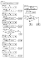
図2に示す如く、本発明の第一の実施形態に係るリークテスト方法では、まず始めに、リークテストに必要な気体を供給するための接続口以外の開口部を所定のシール治具(図示せず)を用いて封止する(STEP-101)。
これによって、ワーク10を、シール治具を用いて塞いだ開口部からはリークテストに用いる気体が漏れ出ることがないように準備しておく。
これによって、ワーク10を、シール治具を用いて塞いだ開口部からはリークテストに用いる気体が漏れ出ることがないように準備しておく。
そして、ワーク10をリークテスター2に接続する。
このとき、リークテスター2と接続する配管7を3系統に分岐し、分岐後の各系統の配管7にそれぞれバルブを設けておく。
図1に示すように、W/Jには、第一のバルブ(以下、VL1と記載する)を備える系統の配管7が接続され、C/Cには、第二のバルブ(以下、VL2と記載する)を備える系統の配管7が接続され、O/Hには、第三のバルブ(以下、VL3と記載する)を備える系統の配管7が接続されている。
このとき、リークテスター2と接続する配管7を3系統に分岐し、分岐後の各系統の配管7にそれぞれバルブを設けておく。
図1に示すように、W/Jには、第一のバルブ(以下、VL1と記載する)を備える系統の配管7が接続され、C/Cには、第二のバルブ(以下、VL2と記載する)を備える系統の配管7が接続され、O/Hには、第三のバルブ(以下、VL3と記載する)を備える系統の配管7が接続されている。
次に、本発明の第一の実施形態に係るリークテスト方法では、図2および図3(a)に示す如く、VL2のみを「開」として、VL1およびVL3を「閉」とする(STEP-102)。
そしてこの状態で、C/Cに所定の圧力Pで気体を供給し、リークテスター2によって、C/Cからリークするエアの総漏れ量T1を計測する(STEP-103)。
そして、このとき測定した総漏れ量T1の情報は、演算装置4に送られ、該演算装置4において記憶される。
尚、このとき測定する総漏れ量T1は、以下の数式1で表される量であり、C/Cから経路R1を通じて外部にリークする外漏れ量Q1と、経路R4を通じてC/CからO/Hにリークする内漏れ量q1と、経路R6を通じてC/CからW/Jにリークする内漏れ量q3を合算した量となっている。
そしてこの状態で、C/Cに所定の圧力Pで気体を供給し、リークテスター2によって、C/Cからリークするエアの総漏れ量T1を計測する(STEP-103)。
そして、このとき測定した総漏れ量T1の情報は、演算装置4に送られ、該演算装置4において記憶される。
尚、このとき測定する総漏れ量T1は、以下の数式1で表される量であり、C/Cから経路R1を通じて外部にリークする外漏れ量Q1と、経路R4を通じてC/CからO/Hにリークする内漏れ量q1と、経路R6を通じてC/CからW/Jにリークする内漏れ量q3を合算した量となっている。

次に、本発明の第一の実施形態に係るリークテスト方法では、図2および図3(b)に示す如く、VL3のみを「開」として、VL1およびVL2を「閉」とする(STEP-104)。
そしてこの状態で、O/Hに所定の圧力Pで気体を供給し、リークテスター2によって、O/Hからリークするエアの総漏れ量T2を計測する(STEP-105)。
そして、このとき測定した総漏れ量T2の情報は、演算装置4に送られ、該演算装置4において記憶される。
尚、このとき測定する総漏れ量T2は、以下の数式2で表される量であり、O/Hから経路R2を通じて外部にリークする外漏れ量Q2と、経路R4を通じてO/HからC/Cにリークする内漏れ量q1と、経路R5を通じてO/HからW/Jにリークする内漏れ量q2を合算した量となっている。
そしてこの状態で、O/Hに所定の圧力Pで気体を供給し、リークテスター2によって、O/Hからリークするエアの総漏れ量T2を計測する(STEP-105)。
そして、このとき測定した総漏れ量T2の情報は、演算装置4に送られ、該演算装置4において記憶される。
尚、このとき測定する総漏れ量T2は、以下の数式2で表される量であり、O/Hから経路R2を通じて外部にリークする外漏れ量Q2と、経路R4を通じてO/HからC/Cにリークする内漏れ量q1と、経路R5を通じてO/HからW/Jにリークする内漏れ量q2を合算した量となっている。

次に、本発明の第一の実施形態に係るリークテスト方法では、図2および図4(a)に示す如く、VL1のみを「開」として、VL2およびVL3を「閉」とする(STEP-106)。
そしてこの状態で、W/Jに所定の圧力Pで気体を供給し、リークテスター2によって、W/Jからリークするエアの総漏れ量T3を計測する(STEP-107)。
そして、このとき測定した総漏れ量T3の情報は、演算装置4に送られ、該演算装置4において記憶される。
尚、このとき測定する総漏れ量T3は、以下の数式3で表される量であり、W/Jから経路R3を通じて外部にリークする外漏れ量Q3と、経路R5を通じてW/JからO/Hにリークする内漏れ量q2と、経路R6を通じてW/JからC/Cにリークする内漏れ量q3を合算した量となっている。
そしてこの状態で、W/Jに所定の圧力Pで気体を供給し、リークテスター2によって、W/Jからリークするエアの総漏れ量T3を計測する(STEP-107)。
そして、このとき測定した総漏れ量T3の情報は、演算装置4に送られ、該演算装置4において記憶される。
尚、このとき測定する総漏れ量T3は、以下の数式3で表される量であり、W/Jから経路R3を通じて外部にリークする外漏れ量Q3と、経路R5を通じてW/JからO/Hにリークする内漏れ量q2と、経路R6を通じてW/JからC/Cにリークする内漏れ量q3を合算した量となっている。

そして、本発明の第一の実施形態に係るリークテスト方法では、演算装置4によって、ここまでで測定をした各総漏れ量T1~T3に基づいて、ワーク10の良品あるいは不良品の判定をする(STEP-108)。
ここでは、各総漏れ量T1~T3が全て閾値以下であれば、ワーク10は良品であると判定し、ここでリークテストを終了する。
一方、各総漏れ量T1~T3のうち閾値を超える項目があれば、さらにリークテストを継続する。
ここでは、各総漏れ量T1~T3が全て閾値以下であれば、ワーク10は良品であると判定し、ここでリークテストを終了する。
一方、各総漏れ量T1~T3のうち閾値を超える項目があれば、さらにリークテストを継続する。
次に、本発明の第一の実施形態に係るリークテスト方法では、上記(STEP-108)でワーク10が良品と判定されなかった場合には、図2および図4(b)に示す如く、全てのバルブ(VL1~VL3)を「開」とする(STEP-109)。
そしてこの状態で、各空間(C/C、O/H、W/J)に所定の圧力Pで気体を供給し、リークテスター2によって、ワーク10からリークするエアの総漏れ量T4を計測する(STEP-110)。
そして、このとき測定した総漏れ量T4の情報は、演算装置4に送られ、該演算装置4において記憶される。
尚、このとき測定する総漏れ量T4は、以下の数式4で表される量であり、C/Cから経路R1を通じてワーク10の外部にリークする外漏れ量Q1と、O/Hから経路R2を通じてワーク10の外部にリークする外漏れ量Q2と、W/Jから経路R3を通じてワーク10の外部にリークする外漏れ量Q3を合算した量となっている。
そしてこの状態で、各空間(C/C、O/H、W/J)に所定の圧力Pで気体を供給し、リークテスター2によって、ワーク10からリークするエアの総漏れ量T4を計測する(STEP-110)。
そして、このとき測定した総漏れ量T4の情報は、演算装置4に送られ、該演算装置4において記憶される。
尚、このとき測定する総漏れ量T4は、以下の数式4で表される量であり、C/Cから経路R1を通じてワーク10の外部にリークする外漏れ量Q1と、O/Hから経路R2を通じてワーク10の外部にリークする外漏れ量Q2と、W/Jから経路R3を通じてワーク10の外部にリークする外漏れ量Q3を合算した量となっている。

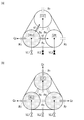
次に、本発明の第一の実施形態に係るリークテスト方法では、図2および図5(a)に示す如く、VL3のみを「閉」として、VL1およびVL2を「開」とする(STEP-111)。
そしてこの状態で、C/CとW/Jに所定の圧力Pで気体を供給し、リークテスター2によって、総漏れ量T5を計測する(STEP-112)。
そして、このとき測定した総漏れ量T5の情報は、演算装置4に送られ、該演算装置4において記憶される。
尚、このとき測定する総漏れ量T5は、以下の数式5で表される量であり、C/Cから経路R1を通じてワーク10の外部にリークする外漏れ量Q1と、W/Jから経路R3を通じてワーク10の外部にリークする外漏れ量Q3と、経路R4を通じてC/CからO/Hにリークする内漏れ量q1と、経路R5を通じてW/JからO/Hにリークする内漏れ量q2を合算した量となっている。
そしてこの状態で、C/CとW/Jに所定の圧力Pで気体を供給し、リークテスター2によって、総漏れ量T5を計測する(STEP-112)。
そして、このとき測定した総漏れ量T5の情報は、演算装置4に送られ、該演算装置4において記憶される。
尚、このとき測定する総漏れ量T5は、以下の数式5で表される量であり、C/Cから経路R1を通じてワーク10の外部にリークする外漏れ量Q1と、W/Jから経路R3を通じてワーク10の外部にリークする外漏れ量Q3と、経路R4を通じてC/CからO/Hにリークする内漏れ量q1と、経路R5を通じてW/JからO/Hにリークする内漏れ量q2を合算した量となっている。

次に、本発明の第一の実施形態に係るリークテスト方法では、図2および図5(b)に示す如く、VL1のみを「閉」として、VL2およびVL3を「開」とする(STEP-113)。
そしてこの状態で、C/CとO/Hに所定の圧力Pで気体を供給し、リークテスター2によって、総漏れ量T6を計測する(STEP-114)。
そして、このとき測定した総漏れ量T6の情報は、演算装置4に送られ、該演算装置4において記憶される。
尚、このとき測定する総漏れ量T6は、以下の数式6で表される量であり、C/Cから経路R1を通じてワーク10の外部にリークする外漏れ量Q1と、O/Hから経路R2を通じてワーク10の外部にリークする外漏れ量Q2と、経路R5を通じてO/HからW/Jにリークする内漏れ量q2と、経路R6を通じてC/CからW/Jにリークする内漏れ量q3を合算した量となっている。
そしてこの状態で、C/CとO/Hに所定の圧力Pで気体を供給し、リークテスター2によって、総漏れ量T6を計測する(STEP-114)。
そして、このとき測定した総漏れ量T6の情報は、演算装置4に送られ、該演算装置4において記憶される。
尚、このとき測定する総漏れ量T6は、以下の数式6で表される量であり、C/Cから経路R1を通じてワーク10の外部にリークする外漏れ量Q1と、O/Hから経路R2を通じてワーク10の外部にリークする外漏れ量Q2と、経路R5を通じてO/HからW/Jにリークする内漏れ量q2と、経路R6を通じてC/CからW/Jにリークする内漏れ量q3を合算した量となっている。

そして、本発明の第一の実施形態に係るリークテスト方法では、図2に示す如く、ここまでで測定をした各総漏れ量T1~T6に基づいて、演算装置4によって、以下の分離アルゴリズムに基づく演算を行って、各漏れ量Q1、Q2、Q3、q1、q2、q3を算出する(STEP-115)。
ここで、本発明の第一の実施形態に係るリークテスト方法において採用している各漏れ量(Q1、Q2、Q3、q1、q2、q3)の分離アルゴリズムについて説明をする。
演算装置4には、後述する分離アルゴリズムが予め導入されており、演算装置4によって、リークテスター2の測定結果(即ち、各総漏れ量T1~T6)に基づいて、各漏れ量(Q1、Q2、Q3、q1、q2、q3)を分離して算出するようにしている。
演算装置4には、後述する分離アルゴリズムが予め導入されており、演算装置4によって、リークテスター2の測定結果(即ち、各総漏れ量T1~T6)に基づいて、各漏れ量(Q1、Q2、Q3、q1、q2、q3)を分離して算出するようにしている。
本発明の第一の実施形態に係るリークテスト方法における分離アルゴリズムでは、以下の数式7に示すように、測定した総漏れ量T1~T3の総和をSQqと規定し、演算装置4によって、各総漏れ量T1~T3の総和SQqを算出する。

また、本発明の第一の実施形態に係るリークテスト方法における分離アルゴリズムでは、以下の数式8に示すように、内漏れ量の総和(即ち、q1+q2+q3)をSqと規定し、演算装置4によって、内漏れ量の総和Sqを算出する。

次に、演算装置4によって、以下の数式9に基づいて、経路R6からの内漏れ量q3を算出する。

次に、演算装置4によって、以下の数式10に基づいて、経路R4からの内漏れ量q1を算出する。

次に、演算装置4によって、以下の数式11に基づいて、経路R5からの内漏れ量q2を算出する。

次に、演算装置4によって、以下の数式12に基づいて、経路R1からの外漏れ量Q1を算出する。

次に、演算装置4によって、以下の数式13に基づいて、経路R2からの外漏れ量Q2を算出する。

次に、演算装置4によって、以下の数式14に基づいて、経路R3からの外漏れ量Q3を算出する。

このように本発明の第一の実施形態に係るリークテスト方法では、上記分離アルゴリズムを採用することで、演算装置4によって、各漏れ量Q1、Q2、Q3、q1、q2、q3を定量的に算出することができる(STEP-116)。
そして、算出した各漏れ量Q1、Q2、Q3、q1、q2、q3に基づいて、演算装置4によって、ワーク10が良品か不良品であるかの判定を行う(STEP-117)。
そして、算出した各漏れ量Q1、Q2、Q3、q1、q2、q3に基づいて、演算装置4によって、ワーク10が良品か不良品であるかの判定を行う(STEP-117)。
ここでは、算出した各漏れ量Q1、Q2、Q3、q1、q2、q3が、全て所定の閾値以下であれば、ワーク10は良品であると判定し、一つでも閾値を超えるものがある場合には、ワーク10は不良品であると判定する構成としている。
ワーク10における各空間C/C、O/H、W/Jは、内部を流通する流体が異なっており、また、使用状態における内部の圧力も異なっている。
一般的なシリンダブロックでは、使用状態における内部の圧力は、圧力が高い方から順に、O/H、W/J、C/Cとなっている。
一般的なシリンダブロックでは、使用状態における内部の圧力は、圧力が高い方から順に、O/H、W/J、C/Cとなっている。
このため、ワーク10における各漏れ量Q1、Q2、Q3、q1、q2、q3の良否判定のための閾値は、それぞれ別途設定することが望ましいが、従来は、各漏れ量Q1、Q2、Q3、q1、q2、q3を定量的に算出することができなかったため、使用状態における圧力差を考慮した適切な良品および不良品の判定を行うことができなかった。
一方、本発明の第一の実施形態に係るリークテスト方法では、ワーク10における各漏れ量Q1、Q2、Q3、q1、q2、q3を定量的に算出することが可能であり、算出した各漏れ量Q1、Q2、Q3、q1、q2、q3に基づいて、使用状態における圧力差を考慮して、適切な良品および不良品の判定を行うことができる。
即ち、本発明の第一の実施形態に係るリークテスト方法によれば、使用上は問題が無いにも関わらず、従来は不良品と判定されていたようなワークを、適切に良品と判定することが可能になり、ワークの廃棄コストを低減し、ひいては、シリンダブロック等のワークの製造コストの低減や製造効率の向上に寄与することができる。
即ち、本発明の第一の実施形態に係るリークテスト方法によれば、使用上は問題が無いにも関わらず、従来は不良品と判定されていたようなワークを、適切に良品と判定することが可能になり、ワークの廃棄コストを低減し、ひいては、シリンダブロック等のワークの製造コストの低減や製造効率の向上に寄与することができる。
即ち、本発明の第一の実施形態に係るリークテスト方法は、区画された三つの空隙部である第一の空間(C/C)と第二の空間(O/H)とおよび第三の空間(W/J)と、を備え、C/Cと外部を連通する第一の外部連通経路たる経路R1と、O/Hと外部を連通する第二の外部連通経路たる経路R2と、W/Jと外部を連通する第三の外部連通経路たる経路R3と、C/CとO/Hを連通する第一の内部連通経路たる経路R4と、O/HとW/Jを連通する第二の内部連通経路たる経路R5と、W/JとC/Cを連通する第三の内部連通経路たる経路R6と、を備える可能性があるワーク10のリークテスト方法であって、C/Cに所定の圧力Pで気体を圧入し、経路R1と経路R4と経路R6から漏れ出る前記気体の総量(即ち、Q1+q1+q3)である第一の総漏れ量T1を取得する第一の工程(STEP-103)と、O/Hに所定の圧力Pで気体を圧入し、経路R2と経路R4と経路R5とから漏れ出る前記気体の総量(即ち、Q2+q1+q2)である第二の総漏れ量T2を取得する第二の工程(STEP-105)と、W/Jに所定の圧力Pで気体を圧入し、経路R3と経路R5と経路R6とから漏れ出る前記気体の総量(即ち、Q3+q2+q3)である第三の総漏れ量T3を取得する第三の工程(STEP-107)と、C/CとO/HとW/Jに所定の圧力Pで気体を圧入し、経路R1と経路R2と経路R3から漏れ出る前記気体の総量(即ち、Q1+Q2+Q3)である第四の総漏れ量T4を取得する第四の工程(STEP-110)と、C/CとW/Jに所定の圧力Pで気体を圧入し、経路R1と経路R3と経路R4と経路R5から漏れ出る前記気体の総量(即ち、Q1+Q3+q1+q2)である第五の総漏れ量T5を取得する第五の工程(STEP-112)と、C/CとO/Hに所定の圧力Pで気体を圧入し、経路R1と経路R2と経路R5と経路R6から漏れ出る前記気体の総量(即ち、Q1+Q2+q2+q3)である第六の総漏れ量T6を取得する第五の工程(STEP-114)と、取得したT1~T6に基づいて、ワーク10に対して前記気体を所定の圧力Pで圧入した場合における、経路R1からの漏れ量である第一の漏れ量(外漏れ量Q1)と、経路R2からの漏れ量である第二の漏れ量(外漏れ量Q2)と、経路R3からの漏れ量である第三の漏れ量(外漏れ量Q3)と、経路R4からの漏れ量である第四の漏れ量(内漏れ量q1)と、経路R5からの漏れ量である第五の漏れ量(内漏れ量q2)と、経路R6からの漏れ量である第六の漏れ量(内漏れ量q3)を算出する工程(STEP-116)と、算出した第一から第六の漏れ量(即ち、各漏れ量Q1、Q2、Q3、q1、q2、q3)に基づいて、ワーク10の良否を判定する工程(STEP-117)と、を備えるものである。
このような構成により、区画された各空間(C/C、O/H、W/J)間での各内漏れ量q1、q2、q3と、各空間(C/C、O/H、W/J)からの各外漏れ量Q1、Q2、Q3を分離して精度よく漏れ量を把握することできる。
これにより、リークテストによる良品・不良品の判定精度を向上させることができ、良品であるにも関わらず、不良品と判定されるワーク10の数量を低減させることができる。
これにより、リークテストによる良品・不良品の判定精度を向上させることができ、良品であるにも関わらず、不良品と判定されるワーク10の数量を低減させることができる。
また、本発明の第一の実施形態に係るリークテスト方法では、第一の工程(STEP-103)と第二の工程(STEP-105)と第三の工程(STEP-107)を実施したあとに、取得した第一から前記第三の各総漏れ量T1~T3に基づいて、ワーク10の良否を判定する第一の判定工程(STEP-108)を実施して、第一の判定工程(STEP-108)において、ワーク10を良品と判定するときには、リークテストを終了し、ワーク10を良品と判定しないときには、さらに、第四の工程(STEP-110)と、第五の工程(STEP-112)と、第六の工程(STEP-114)を実施して、取得した第一から第六の総漏れ量T1~T6に基づいて、ワーク10に対して気体を所定の圧力Pで圧入した場合における、第一から第六の各漏れ量Q1、Q2、Q3、q1、q2、q3を算出する工程(STEP-116)と、算出した各漏れ量Q1、Q2、Q3、q1、q2、q3に基づいて、ワーク10の良否を判定する第二の判定工程(STEP-117)と、を実施するものである。
このような構成により、本発明の第一の実施形態に係るリークテスト方法を適用し、漏れの有無を適切に判断できるようになるのに伴って、リークテストに要する時間が長くなるのを抑制することができる。
次に、本発明の第二の実施形態に係るリークテスト方法によるリークテストの実施状況について、図6を用いて説明をする。
前述したように、本実施形態に示すワーク10が備える各空間(C/C、O/H、W/J)は、内部を流通する流体が異なっており、また、使用状態における内部の圧力も異なっている。
このため、各空間(C/C、O/H、W/J)に対しては、その使用状態における内部の圧力に応じた試験圧力を付与することが望ましい。
そこで、以下に示す本発明の第二の実施形態では、各空間(C/C、O/H、W/J)に対して、異なる試験圧力を付与する場合の、リークテスト方法について説明をする。
尚、この第二の実施形態に係るリークテスト方法は、前述した本発明の第一の実施形態に係るリークテスト方法と同じ検査装置1を用いて実現することができる。
また、第二の実施形態における検査対象たるワークは、第一の実施形態において例示したワーク10と同じである。
前述したように、本実施形態に示すワーク10が備える各空間(C/C、O/H、W/J)は、内部を流通する流体が異なっており、また、使用状態における内部の圧力も異なっている。
このため、各空間(C/C、O/H、W/J)に対しては、その使用状態における内部の圧力に応じた試験圧力を付与することが望ましい。
そこで、以下に示す本発明の第二の実施形態では、各空間(C/C、O/H、W/J)に対して、異なる試験圧力を付与する場合の、リークテスト方法について説明をする。
尚、この第二の実施形態に係るリークテスト方法は、前述した本発明の第一の実施形態に係るリークテスト方法と同じ検査装置1を用いて実現することができる。
また、第二の実施形態における検査対象たるワークは、第一の実施形態において例示したワーク10と同じである。
図6に示す如く、本発明の第二の実施形態に係るリークテスト方法では、まず始めに、リークテストに必要な気体を供給するための接続口以外の開口部を所定のシール治具(図示せず)を用いて封止する(STEP-201)。
これによって、ワーク10を、シール治具を用いて塞いだ開口部からはリークテスト用の気体が漏れ出ることがないように準備しておく。
そして、ワーク10をリークテスター2に接続する。
これによって、ワーク10を、シール治具を用いて塞いだ開口部からはリークテスト用の気体が漏れ出ることがないように準備しておく。
そして、ワーク10をリークテスター2に接続する。
次に、本発明の第二の実施形態に係るリークテスト方法では、図6および図3(a)に示す如く、VL2のみを「開」として、VL1およびVL3を「閉」とする(STEP-202)。
そしてこの状態で、C/Cの使用圧力に対応する所定の圧力P1で気体を供給し、リークテスター2によって、C/Cからリークするエアの総漏れ量T1を計測する(STEP-203)。
そして、このとき測定した総漏れ量T1の情報は、演算装置4に送られ、該演算装置4において記憶される。
尚、このとき測定する総漏れ量T1は、前述した数式1で表される量である。
そしてこの状態で、C/Cの使用圧力に対応する所定の圧力P1で気体を供給し、リークテスター2によって、C/Cからリークするエアの総漏れ量T1を計測する(STEP-203)。
そして、このとき測定した総漏れ量T1の情報は、演算装置4に送られ、該演算装置4において記憶される。
尚、このとき測定する総漏れ量T1は、前述した数式1で表される量である。
次に、本発明の第二の実施形態に係るリークテスト方法では、図6および図3(b)に示す如く、VL3のみを「開」として、VL1およびVL2を「閉」とする(STEP-204)。
そしてこの状態で、O/Hの使用圧力に対応する所定の圧力P2で気体を供給し、リークテスター2によって、O/Hからリークするエアの総漏れ量T2を計測する(STEP-205)。
そして、このとき測定した総漏れ量T2の情報は、演算装置4に送られ、該演算装置4において記憶される。
尚、このとき測定する総漏れ量T2は、前述した数式2で表される量である。
そしてこの状態で、O/Hの使用圧力に対応する所定の圧力P2で気体を供給し、リークテスター2によって、O/Hからリークするエアの総漏れ量T2を計測する(STEP-205)。
そして、このとき測定した総漏れ量T2の情報は、演算装置4に送られ、該演算装置4において記憶される。
尚、このとき測定する総漏れ量T2は、前述した数式2で表される量である。
次に、本発明の第二の実施形態に係るリークテスト方法では、図6および図4(a)に示す如く、VL1のみを「開」として、VL2およびVL3を「閉」とする(STEP-206)。
そしてこの状態で、W/Jの使用圧力に対応する所定の圧力P3で気体を供給し、リークテスター2によって、W/Jからリークするエアの総漏れ量T3を計測する(STEP-207)。
そして、このとき測定した総漏れ量T3の情報は、演算装置4に送られ、該演算装置4において記憶される。
尚、このとき測定する総漏れ量T3は、前述した数式3で表される量である。
そしてこの状態で、W/Jの使用圧力に対応する所定の圧力P3で気体を供給し、リークテスター2によって、W/Jからリークするエアの総漏れ量T3を計測する(STEP-207)。
そして、このとき測定した総漏れ量T3の情報は、演算装置4に送られ、該演算装置4において記憶される。
尚、このとき測定する総漏れ量T3は、前述した数式3で表される量である。
そして、本発明の第二の実施形態に係るリークテスト方法では、演算装置4によって、ここまでで測定をした各総漏れ量T1~T3に基づいて、ワーク10の良品あるいは不良品の判定をする(STEP-208)。
ここでは、各総漏れ量T1~T3が全て閾値以下であれば、ワーク10は良品であると判定し、ここでリークテストを終了する。
一方、各総漏れ量T1~T3のうち閾値を超える項目があれば、さらにリークテストを継続する。
ここでは、各総漏れ量T1~T3が全て閾値以下であれば、ワーク10は良品であると判定し、ここでリークテストを終了する。
一方、各総漏れ量T1~T3のうち閾値を超える項目があれば、さらにリークテストを継続する。
次に、本発明の第二の実施形態に係るリークテスト方法では、上記(STEP-208)でワーク10が良品と判定されなかった場合には、図6および図4(b)に示す如く、全てのバルブ(VL1~VL3)を「開」とする(STEP-209)。
そしてこの状態で、各空間(C/C、O/H、W/J)に所定の圧力P4で気体を供給し、リークテスター2によって、ワーク10からリークするエアの総漏れ量T4を計測する(STEP-210)。
そして、このとき測定した総漏れ量T4の情報は、演算装置4に送られ、該演算装置4において記憶される。
尚、このとき測定する総漏れ量T4は、前述した数式4で表される量である。
また、このときの所定の圧力P4は、各空間(C/C、O/H、W/J)のうち、最も使用圧力が高い空間における使用圧力に対応した圧力とすることが望ましく、本実施形態の場合には、O/Hの使用圧力を基準に圧力P4を設定する。
そしてこの状態で、各空間(C/C、O/H、W/J)に所定の圧力P4で気体を供給し、リークテスター2によって、ワーク10からリークするエアの総漏れ量T4を計測する(STEP-210)。
そして、このとき測定した総漏れ量T4の情報は、演算装置4に送られ、該演算装置4において記憶される。
尚、このとき測定する総漏れ量T4は、前述した数式4で表される量である。
また、このときの所定の圧力P4は、各空間(C/C、O/H、W/J)のうち、最も使用圧力が高い空間における使用圧力に対応した圧力とすることが望ましく、本実施形態の場合には、O/Hの使用圧力を基準に圧力P4を設定する。
次に、本発明の第二の実施形態に係るリークテスト方法では、図6および図5(a)に示す如く、VL3のみを「閉」として、VL1およびVL2を「開」とする(STEP-211)。
そしてこの状態で、C/CとW/Jに所定の圧力P5で気体を供給し、リークテスター2によって、総漏れ量T5を計測する(STEP-212)。
そして、このとき測定した総漏れ量T5の情報は、演算装置4に送られ、該演算装置4において記憶される。
尚、このとき測定する総漏れ量T5は、前述した数式5で表される量である。
また、このときの所定の圧力P5は、C/CとW/Jのうち、使用圧力が高い空間における使用圧力に対応した圧力とすることが望ましく、本実施形態の場合には、W/Jの使用圧力を基準に圧力P5を設定する。
そしてこの状態で、C/CとW/Jに所定の圧力P5で気体を供給し、リークテスター2によって、総漏れ量T5を計測する(STEP-212)。
そして、このとき測定した総漏れ量T5の情報は、演算装置4に送られ、該演算装置4において記憶される。
尚、このとき測定する総漏れ量T5は、前述した数式5で表される量である。
また、このときの所定の圧力P5は、C/CとW/Jのうち、使用圧力が高い空間における使用圧力に対応した圧力とすることが望ましく、本実施形態の場合には、W/Jの使用圧力を基準に圧力P5を設定する。
次に、本発明の第二の実施形態に係るリークテスト方法では、図6および図5(b)に示す如く、VL1のみを「閉」として、VL2およびVL3を「開」とする(STEP-213)。
そしてこの状態で、C/CとO/Hに所定の圧力P6で気体を供給し、リークテスター2によって、総漏れ量T6を計測する(STEP-214)。
そして、このとき測定した総漏れ量T6の情報は、演算装置4に送られ、該演算装置4において記憶される。
尚、このとき測定する総漏れ量T6は、前述した数式6で表される量である。
また、このときの所定の圧力P6は、C/CとO/Hのうち、使用圧力が高い空間における使用圧力に対応した圧力とすることが望ましく、本実施形態の場合には、O/Hの使用圧力を基準に圧力P6を設定する。
そしてこの状態で、C/CとO/Hに所定の圧力P6で気体を供給し、リークテスター2によって、総漏れ量T6を計測する(STEP-214)。
そして、このとき測定した総漏れ量T6の情報は、演算装置4に送られ、該演算装置4において記憶される。
尚、このとき測定する総漏れ量T6は、前述した数式6で表される量である。
また、このときの所定の圧力P6は、C/CとO/Hのうち、使用圧力が高い空間における使用圧力に対応した圧力とすることが望ましく、本実施形態の場合には、O/Hの使用圧力を基準に圧力P6を設定する。
そして、本発明の第二の実施形態に係るリークテスト方法では、図6に示す如く、演算装置4によって、ここまでで測定をした各総漏れ量T1~T6を、代表検査圧P0における各総漏れ量に換算する(STEP-215)。
そして、代表検査圧P0における漏れ量に換算した後の各総漏れ量T1~T6に基づいて、演算装置4によって、以下の分離アルゴリズムに基づく演算を行って、各漏れ量Q1、Q2、Q3、q1、q2、q3を算出する(STEP-216)。
尚、このときの代表検査圧P0は、各空間(C/C、O/H、W/J)のうち、最も使用圧力が高い空間における使用圧力に対応した圧力とすることが望ましく、本実施形態の場合には、O/Hの使用圧力を基準に代表検査圧P0を設定する。
そして、代表検査圧P0における漏れ量に換算した後の各総漏れ量T1~T6に基づいて、演算装置4によって、以下の分離アルゴリズムに基づく演算を行って、各漏れ量Q1、Q2、Q3、q1、q2、q3を算出する(STEP-216)。
尚、このときの代表検査圧P0は、各空間(C/C、O/H、W/J)のうち、最も使用圧力が高い空間における使用圧力に対応した圧力とすることが望ましく、本実施形態の場合には、O/Hの使用圧力を基準に代表検査圧P0を設定する。
本発明の第二の実施形態に係るリークテスト方法における分離アルゴリズムは、本発明の第一の実施形態に係るリークテスト方法における分離アルゴリズムと同様であり、前述した数式7から数式14に基づいて、演算装置4によって、各漏れ量Q1、Q2、Q3、q1、q2、q3を定量的に算出する(STEP-217)。
そして、算出した各漏れ量Q1、Q2、Q3、q1、q2、q3に基づいて、演算装置4によって、ワーク10が良品か不良品であるかの判定を行う(STEP-218)。
そして、算出した各漏れ量Q1、Q2、Q3、q1、q2、q3に基づいて、演算装置4によって、ワーク10が良品か不良品であるかの判定を行う(STEP-218)。
このように、本発明の第二の実施形態に係るリークテスト方法では、使用状態における圧力を考慮して、ワーク10における各漏れ量Q1、Q2、Q3、q1、q2、q3を定量的に算出することが可能であり、より適切に良品および不良品の判定を行うことができる。
本発明は、シリンダブロック、シリンダヘッド等に代表されるエンジンを構成するワークのみならず、三つに区画された空隙部を有するワークに対して広く適用することが可能であり、また本発明を応用すれば、四つ以上に区画された空隙部を有するワークに対するリークテストを容易に精度よく行うことができる。
Claims (2)
- 区画された三つの空隙部である第一の空間と第二の空間と第三の空間と、
を備え、
前記第一の空間と外部を連通する第一の外部連通経路と、
前記第二の空間と外部を連通する第二の外部連通経路と、
前記第三の空間と外部を連通する第三の外部連通経路と、
前記第一の空間と前記第二の空間を連通する第一の内部連通経路と、
前記第二の空間と前記第三の空間を連通する第二の内部連通経路と、
前記第三の空間と前記第一の空間を連通する第三の内部連通経路と、
を備える可能性があるワークのリークテスト方法であって、
前記第一の空間に所定の圧力で気体を圧入し、
前記第一の内部連通経路と前記第三の内部連通経路と前記第一の外部連通経路から漏れ出る前記気体の総量である第一の総漏れ量を取得する第一の工程と、
前記第二の空間に所定の圧力で気体を圧入し、
前記第一の内部連通経路と前記第二の内部連通経路と前記第二の外部連通経路から漏れ出る前記気体の総量である第二の総漏れ量を取得する第二の工程と、
前記第三の空間に所定の圧力で気体を圧入し、
前記第二の内部連通経路と前記第三の内部連通経路と前記第三の外部連通経路から漏れ出る前記気体の総量である第三の総漏れ量を取得する第三の工程と、
前記第一の空間と前記第二の空間と前記第三の空間に所定の圧力で気体を圧入し、
前記第一の外部連通経路と前記第二の外部連通経路と前記第三の外部連通経路から漏れ出る前記気体の総量である第四の総漏れ量を取得する第四の工程と、
前記第一の空間と前記第三の空間に所定の圧力で気体を圧入し、
前記第一の外部連通経路と前記第三の外部連通経路と前記第一の内部連通経路と前記第二の内部連通経路から漏れ出る前記気体の総量である第五の総漏れ量を取得する第五の工程と、
前記第一の空間と前記第二の空間に所定の圧力で気体を圧入し、
前記第一の外部連通経路と前記第二の外部連通経路と前記第二の内部連通経路と前記第三の内部連通経路から漏れ出る前記気体の総量である第六の総漏れ量を取得する第六の工程と、
取得した前記第一から第六の総漏れ量に基づいて、
前記ワークに対して前記気体を所定の圧力で圧入した場合における、前記第一の外部連通経路からの漏れ量である第一の漏れ量と、前記第二の外部連通経路からの漏れ量である第二の漏れ量と、前記第三の外部連通経路からの漏れ量である第三の漏れ量と、前記第一の内部連通経路からの漏れ量である第四の漏れ量と、前記第二の内部連通経路からの漏れ量である第五の漏れ量と、前記第三の内部連通経路からの漏れ量である第六の漏れ量を、算出する工程と、
算出した前記第一から第六の漏れ量に基づいて、
前記ワークの良否を判定する工程と、
を備える、
ことを特徴とするリークテスト方法。 - 区画された三つの空隙部である第一の空間と第二の空間と第三の空間と、
を備え、
前記第一の空間と外部を連通する第一の外部連通経路と、
前記第二の空間と外部を連通する第二の外部連通経路と、
前記第三の空間と外部を連通する第三の外部連通経路と、
前記第一の空間と前記第二の空間を連通する第一の内部連通経路と、
前記第二の空間と前記第三の空間を連通する第二の内部連通経路と、
前記第三の空間と前記第一の空間を連通する第三の内部連通経路と、
を備える可能性があるワークのリークテスト方法であって、
前記第一の空間に所定の圧力で気体を圧入し、
前記第一の内部連通経路と前記第三の内部連通経路と前記第一の外部連通経路から漏れ出る前記気体の総量である第一の総漏れ量を取得する第一の工程と、
前記第二の空間に所定の圧力で気体を圧入し、
前記第一の内部連通経路と前記第二の内部連通経路と前記第二の外部連通経路から漏れ出る前記気体の総量である第二の総漏れ量を取得する第二の工程と、
前記第三の空間に所定の圧力で気体を圧入し、
前記第二の内部連通経路と前記第三の内部連通経路と前記第三の外部連通経路から漏れ出る前記気体の総量である第三の総漏れ量を取得する第三の工程と、
を実施したあとに、
取得した前記第一から前記第三の総漏れ量に基づいて、
前記ワークの良否を判定する第一の判定工程を実施し、
前記第一の判定工程において、
前記ワークを良品と判定するときには、
リークテストを終了し、
前記ワークを良品と判定しないときには、
さらに、
前記第一の空間と前記第二の空間と前記第三の空間に所定の圧力で気体を圧入し、
前記第一の外部連通経路と前記第二の外部連通経路と前記第三の外部連通経路から漏れ出る前記気体の総量である第四の総漏れ量を取得する第四の工程と、
前記第一の空間と前記第三の空間に所定の圧力で気体を圧入し、
前記第一の外部連通経路と前記第三の外部連通経路と前記第一の内部連通経路と前記第二の内部連通経路から漏れ出る前記気体の総量である第五の総漏れ量を取得する第五の工程と、
前記第一の空間と前記第二の空間に所定の圧力で気体を圧入し、
前記第一の外部連通経路と前記第二の外部連通経路と前記第二の内部連通経路と前記第三の内部連通経路から漏れ出る前記気体の総量である第六の総漏れ量を取得する第六の工程と、
取得した前記第一から第六の総漏れ量に基づいて、
前記ワークに対して前記気体を所定の圧力で圧入した場合における、前記第一の外部連通経路からの漏れ量である第一の漏れ量と、前記第二の外部連通経路からの漏れ量である第二の漏れ量と、前記第三の外部連通経路からの漏れ量である第三の漏れ量と、前記第一の内部連通経路からの漏れ量である第四の漏れ量と、前記第二の内部連通経路からの漏れ量である第五の漏れ量と、前記第三の内部連通経路からの漏れ量である第六の漏れ量を、算出する工程と、
算出した前記第一から第六の漏れ量に基づいて、
前記ワークの良否を判定する第二の判定工程と、
を実施する、
ことを特徴とするリークテスト方法。
Priority Applications (2)
| Application Number | Priority Date | Filing Date | Title |
|---|---|---|---|
| CN201380068950.1A CN104903694B (zh) | 2012-11-30 | 2013-11-07 | 泄漏试验方法 |
| US14/647,288 US9551626B2 (en) | 2012-11-30 | 2013-11-07 | Leak testing method |
Applications Claiming Priority (2)
| Application Number | Priority Date | Filing Date | Title |
|---|---|---|---|
| JP2012262486A JP5742824B2 (ja) | 2012-11-30 | 2012-11-30 | リークテスト方法 |
| JP2012-262486 | 2012-11-30 |
Publications (1)
| Publication Number | Publication Date |
|---|---|
| WO2014084017A1 true WO2014084017A1 (ja) | 2014-06-05 |
Family
ID=50827663
Family Applications (1)
| Application Number | Title | Priority Date | Filing Date |
|---|---|---|---|
| PCT/JP2013/080129 Ceased WO2014084017A1 (ja) | 2012-11-30 | 2013-11-07 | リークテスト方法 |
Country Status (4)
| Country | Link |
|---|---|
| US (1) | US9551626B2 (ja) |
| JP (1) | JP5742824B2 (ja) |
| CN (1) | CN104903694B (ja) |
| WO (1) | WO2014084017A1 (ja) |
Citations (2)
| Publication number | Priority date | Publication date | Assignee | Title |
|---|---|---|---|---|
| JPH09159566A (ja) * | 1995-12-08 | 1997-06-20 | Mitsubishi Motors Corp | エンジンのリークテスト方法 |
| JP2000121485A (ja) * | 1998-10-19 | 2000-04-28 | Nissan Motor Co Ltd | 気密性検査方法 |
Family Cites Families (5)
| Publication number | Priority date | Publication date | Assignee | Title |
|---|---|---|---|---|
| CN1241717A (zh) * | 1999-05-10 | 2000-01-19 | 唐山爱信齿轮有限责任公司 | 一种干式密封检测方法及装置 |
| FI119702B (fi) * | 2003-10-17 | 2009-02-13 | Waertsilae Finland Oy | Polttomoottorin laitteisto korkeapaineputken vuotoja varten |
| CN2819199Y (zh) * | 2005-09-21 | 2006-09-20 | 上海大众汽车有限公司 | 燃油系统密封测试装置 |
| JP2007218122A (ja) * | 2006-02-14 | 2007-08-30 | Denso Corp | 漏れ診断装置 |
| KR100857348B1 (ko) * | 2006-12-14 | 2008-09-05 | 현대자동차주식회사 | 실린더블록의 크랙 검지장치 및 그 방법 |
-
2012
- 2012-11-30 JP JP2012262486A patent/JP5742824B2/ja not_active Expired - Fee Related
-
2013
- 2013-11-07 US US14/647,288 patent/US9551626B2/en not_active Expired - Fee Related
- 2013-11-07 CN CN201380068950.1A patent/CN104903694B/zh not_active Expired - Fee Related
- 2013-11-07 WO PCT/JP2013/080129 patent/WO2014084017A1/ja not_active Ceased
Patent Citations (2)
| Publication number | Priority date | Publication date | Assignee | Title |
|---|---|---|---|---|
| JPH09159566A (ja) * | 1995-12-08 | 1997-06-20 | Mitsubishi Motors Corp | エンジンのリークテスト方法 |
| JP2000121485A (ja) * | 1998-10-19 | 2000-04-28 | Nissan Motor Co Ltd | 気密性検査方法 |
Also Published As
| Publication number | Publication date |
|---|---|
| JP5742824B2 (ja) | 2015-07-01 |
| CN104903694A (zh) | 2015-09-09 |
| US20150308918A1 (en) | 2015-10-29 |
| CN104903694B (zh) | 2018-04-24 |
| US9551626B2 (en) | 2017-01-24 |
| JP2014109446A (ja) | 2014-06-12 |
Similar Documents
| Publication | Publication Date | Title |
|---|---|---|
| Ostasz et al. | Quality management of aluminum pistons with the use of quality control points | |
| KR102093571B1 (ko) | 누설 검사 장치 및 방법 | |
| TWI494554B (zh) | Method and device for differential pressure measurement | |
| Rieger et al. | Fatigue crack growth in full-scale railway axles–Influence of secondary stresses and load sequence effects | |
| CN103410892A (zh) | 液压盘式制动器泄漏及液压油混入空气故障在线诊断方法 | |
| JP2009092585A (ja) | リーク検査装置 | |
| CN106441851A (zh) | 一种机械零件疲劳寿命的检测方法 | |
| JP5742824B2 (ja) | リークテスト方法 | |
| JP2018009955A (ja) | リーク検査方法 リーク検査装置 | |
| Bodyakina et al. | Diagnostics of hydraulic density of plunger couple of tractor diesel | |
| CN106202740B (zh) | 一种轴承盖与轴承座接触面摩擦系数的试验确定法 | |
| CN104742894B (zh) | 一种基于解析模型的气制动系统故障检测方法 | |
| CN104234775B (zh) | 一种润滑系统关键压力测量方法 | |
| JP2007108102A (ja) | 流量式性能検査装置及び検査方法 | |
| JP2007183261A (ja) | エンジンオイル漏れ試験システム及び方法 | |
| Mysiuk et al. | Determining the Place of Depressurization of Underground Pipelines (Gas Pipelines): New Solutions in Industry based on Thermal Image Analysis Using Computer Vision | |
| JP3559893B2 (ja) | 気密性検査方法 | |
| JP4756602B2 (ja) | オイルホールの漏れ検査方法 | |
| CN108475797A (zh) | 用于诊断泄漏的方法以及燃料电池系统 | |
| US8788219B2 (en) | Method of determining an edge of an anomaly, method of determining interaction, method of aligning, computer program product, and data carrier | |
| JP4355933B2 (ja) | 漏洩試験方法及び装置 | |
| JP2003021570A (ja) | 漏れ計測方法 | |
| CN103575473A (zh) | 发动机水循环漏油检测系统及应用该系统进行漏油检测的方法 | |
| EP3785002A1 (en) | Method of testing an integrity of a structure separating a chamber from an adjacent environment, and related apparatus | |
| CN116446978A (zh) | 发动机润滑系统的工况检测方法、电子设备和存储介质 |
Legal Events
| Date | Code | Title | Description |
|---|---|---|---|
| 121 | Ep: the epo has been informed by wipo that ep was designated in this application |
Ref document number: 13858034 Country of ref document: EP Kind code of ref document: A1 |
|
| WWE | Wipo information: entry into national phase |
Ref document number: 14647288 Country of ref document: US |
|
| NENP | Non-entry into the national phase |
Ref country code: DE |
|
| 122 | Ep: pct application non-entry in european phase |
Ref document number: 13858034 Country of ref document: EP Kind code of ref document: A1 |