WO2014084014A1 - 流体制御装置 - Google Patents
流体制御装置 Download PDFInfo
- Publication number
- WO2014084014A1 WO2014084014A1 PCT/JP2013/080074 JP2013080074W WO2014084014A1 WO 2014084014 A1 WO2014084014 A1 WO 2014084014A1 JP 2013080074 W JP2013080074 W JP 2013080074W WO 2014084014 A1 WO2014084014 A1 WO 2014084014A1
- Authority
- WO
- WIPO (PCT)
- Prior art keywords
- fluid control
- control device
- pipe
- control devices
- support member
- Prior art date
- Legal status (The legal status is an assumption and is not a legal conclusion. Google has not performed a legal analysis and makes no representation as to the accuracy of the status listed.)
- Ceased
Links
Images


Classifications
-
- F—MECHANICAL ENGINEERING; LIGHTING; HEATING; WEAPONS; BLASTING
- F16—ENGINEERING ELEMENTS AND UNITS; GENERAL MEASURES FOR PRODUCING AND MAINTAINING EFFECTIVE FUNCTIONING OF MACHINES OR INSTALLATIONS; THERMAL INSULATION IN GENERAL
- F16K—VALVES; TAPS; COCKS; ACTUATING-FLOATS; DEVICES FOR VENTING OR AERATING
- F16K27/00—Construction of housing; Use of materials therefor
-
- F—MECHANICAL ENGINEERING; LIGHTING; HEATING; WEAPONS; BLASTING
- F16—ENGINEERING ELEMENTS AND UNITS; GENERAL MEASURES FOR PRODUCING AND MAINTAINING EFFECTIVE FUNCTIONING OF MACHINES OR INSTALLATIONS; THERMAL INSULATION IN GENERAL
- F16K—VALVES; TAPS; COCKS; ACTUATING-FLOATS; DEVICES FOR VENTING OR AERATING
- F16K49/00—Means in or on valves for heating or cooling
- F16K49/002—Electric heating means
-
- F—MECHANICAL ENGINEERING; LIGHTING; HEATING; WEAPONS; BLASTING
- F16—ENGINEERING ELEMENTS AND UNITS; GENERAL MEASURES FOR PRODUCING AND MAINTAINING EFFECTIVE FUNCTIONING OF MACHINES OR INSTALLATIONS; THERMAL INSULATION IN GENERAL
- F16K—VALVES; TAPS; COCKS; ACTUATING-FLOATS; DEVICES FOR VENTING OR AERATING
- F16K27/00—Construction of housing; Use of materials therefor
- F16K27/003—Housing formed from a plurality of the same valve elements
-
- F—MECHANICAL ENGINEERING; LIGHTING; HEATING; WEAPONS; BLASTING
- F16—ENGINEERING ELEMENTS AND UNITS; GENERAL MEASURES FOR PRODUCING AND MAINTAINING EFFECTIVE FUNCTIONING OF MACHINES OR INSTALLATIONS; THERMAL INSULATION IN GENERAL
- F16K—VALVES; TAPS; COCKS; ACTUATING-FLOATS; DEVICES FOR VENTING OR AERATING
- F16K49/00—Means in or on valves for heating or cooling
-
- Y—GENERAL TAGGING OF NEW TECHNOLOGICAL DEVELOPMENTS; GENERAL TAGGING OF CROSS-SECTIONAL TECHNOLOGIES SPANNING OVER SEVERAL SECTIONS OF THE IPC; TECHNICAL SUBJECTS COVERED BY FORMER USPC CROSS-REFERENCE ART COLLECTIONS [XRACs] AND DIGESTS
- Y10—TECHNICAL SUBJECTS COVERED BY FORMER USPC
- Y10T—TECHNICAL SUBJECTS COVERED BY FORMER US CLASSIFICATION
- Y10T137/00—Fluid handling
- Y10T137/6416—With heating or cooling of the system
Definitions
- the present invention relates to a fluid control device used in a semiconductor manufacturing apparatus or the like, and more particularly to a fluid control device having a heating means and formed by integrating a plurality of fluid control devices.
- a plurality of fluid control devices are arranged in series, and a plurality of lines formed by connecting them without using pipes or joints are arranged in parallel on a base member. Integration is progressing in the area.
- a heating means may be required, and downsizing including the heating means is an issue.
- a laminated block is used, and the laminated block is installed so as to cover the piping, and a fixing portion for fixing a lower flow path block on which a part of the fluid control device is placed is laminated block. It is disclosed that heat transfer is performed when heated by a heater.
- the laminated block is used regardless of the presence or absence of the heater to support the lower flow path block (passage block), and the laminated block (pipe heating member in the case of having a heater) There was a problem that attachment and removal could not be performed freely. Further, in the fluid control device disclosed in Patent Document 1, when a plurality of one line composed of a plurality of fluid control devices arranged in series is installed on the base member, each passage block is directly attached to the base member. There was also a problem that it took time and effort to add and change units.
- the object of the present invention is to allow the pipe heating member to be freely attached and detached, and to easily add or change one line consisting of a plurality of fluid control devices arranged in series as a unit.
- the object is to provide a fluid control device.
- the fluid control device includes a plurality of fluid control devices arranged in series, a plurality of passage blocks arranged below the plurality of fluid control devices and supporting the plurality of fluid control devices, and a plurality of fluids
- a fluid control device comprising a control device and heaters arranged on both sides of some of the plurality of passage blocks, and pipes passed below the plurality of passage blocks.
- 1 comprises a plate-like support member to which the support member is detachably attached, a hollow metal attachment member to which the support member is fixed to the upper surface and detachably attached to the base member, a bottom wall and a pair of side walls.
- a pipe heating member is provided that accommodates the pipe between the pair of side walls and is fitted into the mounting member so as to contact the mounting member.
- This fluid control device constitutes one line of a fluid control device (integrated fluid control device) composed of a plurality of lines.
- the fluid control device constituting one line is obtained by fixing the support member to which the fluid control device and the passage block are attached to the upper surface of the attachment member.
- the fluid control device is attached to the base member in the housing to form a plurality of lines.
- the required fluid control device and the passage block can be attached to the support member in advance outside the housing. Installation work can be performed easily.
- one line can be installed on the base member in one operation, and therefore, addition or change can be easily performed in units of one line composed of a plurality of fluid control devices arranged in series. .
- the pipe heating member is, for example, an aluminum block-like member, and is close to the pipe, so that heat from the heater can be efficiently transferred to the pipe. Even if this is omitted, the pipe heating member is a part that does not affect the attachment of the fluid control device and the passage block, and can be freely attached and detached.
- the mounting member includes a pair of side walls and end walls that connect the end portions of the side walls, and through holes are formed in each side wall, and the male screw inserted into the through holes is a pipe heating member. It is preferable that the pipe heating member is detachably attached to the attachment member by being screwed to the screw portion because it is provided on the side wall of the pipe. If it does in this way, attachment and detachment to the attachment member of a piping heating member will become easy.
- the mounting member further includes an upper protruding edge portion provided on the upper surface of the end wall so as to protrude inward and to which both ends of the support member are fixed. If it does in this way, attachment and detachment to the attachment member of a support member will become easy.
- the mounting member further includes a lower protruding edge portion that is provided on the lower surface of the end wall so as to protrude outward and is fixed to the base member. If it does in this way, attachment and detachment to a base member of an attachment member will become easy.
- Support members and mounting members can be used on lines where no heater is used. In this case, the pipe heating member may be omitted.
- the pipe heating member can be freely attached and detached, and one line consisting of a plurality of fluid control devices arranged in series can be added as a unit. Changes can be made easily.
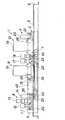
- FIG. 1 is a side view of an embodiment of a fluid control apparatus according to the present invention.
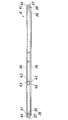
- FIG. 2 is a plan view of FIG.
- FIG. 3 is a cross-sectional view of FIG.
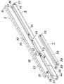
- FIG. 4 is an exploded perspective view of a main part of FIG.
- FIG. 5 is a plan view showing the mounting member.
- FIG. 1 the upper and lower sides in FIG. 1 are referred to as upper and lower sides
- the right in FIG. 1 is referred to as front
- the left is referred to as rear
- the left and right are referred to rearward.
- This front / rear / up / down / left / right is convenient, and the front / rear may be reversed or the top / bottom may be left / right.
- one embodiment of a fluid control device (1) includes a plurality of fluid control devices (11), (12), (13) arranged in series in the front-rear direction. 14) (15) (16) (17) (18) (19) (20) (21) having an upper layer (2) and a plurality of fluid control devices (11) (12) (13) (14) ( 15) (16) (17) (18) (19) (20) (21) lower layer (3) having a plurality of passage blocks (22) (23) supporting upper layer (2) and lower layer (3) a plate-like heater (4) for heating the required part, a support member (5) for supporting the passage block (22) (23) of the lower layer (3), and the lower side of the support member (5) And a pipe heating member (7) accommodated in the mounting member (6).
- a plurality of passage blocks (22) and (23) as lower layer constituent elements are detachably attached to the support member (5) at a required interval by male screws (25), and the passage blocks (22) (23 (11) (12) (13) (14) (15) (16) (17) (18) (19) (20) (21) Removably attached to the corresponding passage blocks (22) and (23) with male screws (26).
- a support member (5) supporting a plurality of fluid control devices (11) (12) (13) (14) (15) (16) (17) (18) (19) (20) (21) is attached.
- a fluid control unit (for example, a gas supply device for semiconductor manufacturing) having a plurality of fluid control devices (lines) (1) formed by 16) (17) (18) (19) (20) (21) is formed. .
- a second flow rate controller (19), a filter (20), and an outlet portion (10) having a gas outlet joint (21) are provided.
- the I-shaped passage (not shown) in the passage block (23) arranged at the outlet of the pressure detector (14) and a passage block (23) arranged in the second gas inlet of the third on-off valve (18) is communicated with a pipe (24).
- the pipe (24) extends below the plurality of passage blocks (22) and (23) from the inlet side to the outlet side, and both ends of the pipe (24) extend upward and open upward. Yes.
- the third on-off valve (18) is a three-way valve. By operating the third on-off valve (18), the gas from the first gas inlet (8) is shut off and opened.
- the heater (4) is in the form of a plate called a panel heater, and a plurality of fluid control devices (11) (12) (13) (14) (15) (16) (17) (18) (19), (20), (21), a plurality of passage blocks (22), (23), a support member (5), and an attachment member (6) are provided so as to be sandwiched from both sides.
- a predetermined interval in the front-rear direction is provided between the pressure detector (14) and the second gas inlet joint (15), and a plate-like interval holding member (45) is provided to fill this interval.
- the heater (4) is in contact with the spacing member (45), thereby preventing the heater (4) from twisting. This interval may not be present, and in this case, the interval holding member (45) can be omitted.
- the support member (5) is made of a flat plate made of stainless steel.
- the support member (5) is arranged along the arrangement direction of the plurality of fluid control devices (11) (12) (13) (14) (15) (16) (17) (18) (19) (20) (21).
- the length is larger than the total length (in the front-rear direction), and both front and rear ends thereof are detachably attached to the attachment member (6) with external screws (27).
- the support member (5) is divided into two at the exact center in the width direction. Accordingly, the support member (5) can be attached to the attachment member (6) so as to sandwich both ends of the pipe (24) from both sides in the left-right direction.
- the mounting member (6) is hollow so that the pipe heating member (7) can be accommodated therein, and heat generated by the heater (4) is efficiently transmitted to the pipe heating member (7). It is made of metal such as stainless steel.
- the front and rear ends of the attachment member (6) are detachably attached to the base member by external screws (28).
- the pipe heating member (7) is a block member made of aluminum having a U-shaped cross section, and includes a bottom wall (29) and a pair of side walls (30) as shown in FIG.
- the pipe (24) is accommodated between the pair of side walls (30) so that the side wall (30) and the pipe (24) are close to or in contact with each other, and the outer surface of each side wall (30) is attached to the mounting member ( It is fitted in the mounting member (6) so as to contact the inner surface of 6).
- the pipe heating member (7) is in contact with the mounting member (6) that is in contact with the heater (4), and is close to or in contact with the pipe (24), so that heat from the heater (4) is obtained. Is efficiently transmitted to the pipe (24).
- the support member (5) includes a through hole (31) for inserting a male screw (27) for attaching the support member (5) to the attachment member (6), and A plurality of female screws (32) to which male screws (25) for fixing the plurality of passage blocks (22) (23) to the support member (5) are screwed together, and a pipe communicated with the passage block (23) A through hole (33) for inserting the end of (24) is provided.
- the mounting member (6) protrudes inward in the front-rear direction on a pair of side walls (34), an end wall (35) connecting the end portions of the side walls (34), and an upper surface of the end wall (35).
- An upper front and rear projecting edge portion (36) that is provided and fixed to both front and rear end portions of the support member (5), and is provided on the lower surface of the end wall (35) so as to protrude outward in the front and rear direction and is fixed to the base member.
- a through hole (38) for attaching the pipe heating member (7) is formed in each side wall (34) of the attachment member (6).
- a female thread portion (39) is formed on the side wall (30) of the pipe heating member (7) so as to correspond to the through hole (38) of the side wall (34) of the mounting member (6).
- the male screw (40) shown in FIG. 1 is inserted into the through hole (38) of the side wall (34) of the mounting member (6), and is inserted into the female screw part (39) of the side wall (30) of the pipe heating member (7).
- the pipe heating member (7) is detachably attached to the attachment member (6) by being screwed together.
- a female thread portion (41) to which a male screw (27) for attaching the support member (5) to the attachment member (6) is screwed is formed on the upper front and rear protruding edge portion (36) of the attachment member (6). .
- protrusions (42) protruding in the left-right direction are provided at a predetermined interval in the front-rear direction, and these protrusions (42) are also supporting members.
- a female screw portion (43) is formed in which a male screw (27) for attaching (5) to the attachment member (6) is screwed together.
- a through hole (44) through which a male screw (not shown) for fixing the mounting member (6) to the base member is inserted is formed in the lower front and rear protruding edge (37) of the mounting member (6). Yes.
- the fluid control device (1) constitutes one line of one device (integrated fluid control device), and a plurality of lines (1) are arranged in parallel on the base member at a predetermined interval.
- the integrated fluid control device is used as a gas supply device for semiconductor manufacturing in combination with other devices, so the area of the base member is limited, and it is desired to reduce the installation area. Yes.
- the fluid control device (1) of this embodiment since the pipe (24) is arranged below the passage blocks (22) and (23), the installation area can be reduced. Since the pipe heating member (7) for heating the pipe (24) is housed in the mounting member (6), the installation area is not increased by the pipe heating member (7).
- the fluid control device (1) is attached to the base member in the housing to form a required line.
- the required fluid control device (11) (12) (13) (14) (15) ( 16) (17) (18) (19) (20) (21) and passage block (22) (23) can be attached to the support member (5) in advance outside the housing, making this installation work easy. It can be carried out.
- the attachment of the support member (5) to the attachment member (6) may be performed before the attachment member (6) is attached to the base member, and the support member (6) attached to the base member is attached to the support member (6). 5) may be attached. In any case, one line can be installed on the base member in one operation.
- the pipe heating member (7) is composed of other members (multiple fluid control devices (11) (12) (13) (14) (15) (16) (17) (18) (19) (20) (21) Also, with the passage blocks (22) and (23)) being left as they are, they can be mounted and removed independently, and can be freely mounted and removed.
- each fluid control device (11) (12) (13) (14) (15) (16) (17) (18) (19) (20) (21) can be taken out independently Since there are no parts configured by attaching a plurality of fluid control devices to one block, each fluid control device (11) (12) (13) (14) (15) (16) (17 ) (18) (19) (20) (21) are easy to maintain and change. Moreover, since both ends of the pipe (24) extend upward and open upward, it is easy to connect to the passage block (23) sandwiched between the passage blocks (22) on both sides, The length in the front-rear direction can be shortened compared to the case where the end of the pipe (24) is open forward or rearward and the front and rear ends are welded to the passage block.
- the pipe (24) is connected to the pressure detector (14) on the rear side (inlet side) of the first flow rate controller (16) and the rear side (inlet side) of the second flow rate controller (19).
- the third on-off valve (18) is provided so as to be connected, so that two flow controllers (a thermal mass flow controller such as a mass flow controller and a pressure flow controller) (16) (19 ) Is easy to install on one line.
- the fluid control device connected by the pipe (24) is not limited to the illustrated example.
- the configuration above the support member (5) that is, the configuration of the fluid control device and the passage block is not limited to the illustrated one, and various configurations can be adopted.
- the present invention is suitable for use in a fluid control device provided with a pipe heating member.
- the pipe heating member can be freely attached and detached, and addition or change can be easily performed in units of one line composed of a plurality of fluid control devices arranged in series. Therefore, the ease of manufacturing the fluid control device can be improved.
Landscapes
- Engineering & Computer Science (AREA)
- General Engineering & Computer Science (AREA)
- Mechanical Engineering (AREA)
- Valve Housings (AREA)
- Details Of Valves (AREA)
- Chemical & Material Sciences (AREA)
- Feeding, Discharge, Calcimining, Fusing, And Gas-Generation Devices (AREA)
- Organic Chemistry (AREA)
- Chemical Kinetics & Catalysis (AREA)
- Physics & Mathematics (AREA)
- Thermal Sciences (AREA)
- Combustion & Propulsion (AREA)
Abstract
Description
Claims (4)
- 直列状に配された複数の流体制御機器と、複数の流体制御機器の下側に配されて複数の流体制御機器を支持する複数の通路ブロックと、複数の流体制御機器および複数の通路ブロックのいくつかにまたがってその両側に配置されたヒータと、複数の通路ブロックの下側に通された配管とを備えている流体制御装置であって、
複数の通路ブロックが着脱可能に取り付けられている板状の支持部材と、支持部材が上面に固定されてベース部材に着脱可能に取り付けられる中空状の金属製取付部材と、底壁および1対の側壁からなり1対の側壁間に配管を収納して取付部材内に取付部材に当接するように嵌め入れられる配管加熱部材とを備えていることを特徴とする流体制御装置。 - 取付部材は、1対の側壁と、側壁の端部同士を連結する端壁とを備えており、各側壁に貫通孔が形成されており、該貫通孔に挿通されたおねじが配管加熱部材の側壁に設けられためねじ部にねじ合わされることで、配管加熱部材が取付部材に着脱可能に取り付けられていることを特徴とする請求項1の流体制御装置。
- 取付部材は、端壁上面に内方に突出するように設けられて支持部材の両端部が固定される上側突出縁部をさらに備えていることを特徴とする請求項1の流体制御装置。
- 取付部材は、端壁下面に外方に突出するように設けられてベース部材に固定される下側突出縁部をさらに備えていることを特徴とする請求項1から3までのいずれかに記載の流体制御装置。
Priority Applications (4)
| Application Number | Priority Date | Filing Date | Title |
|---|---|---|---|
| KR1020157011434A KR101674849B1 (ko) | 2012-11-29 | 2013-11-07 | 유체 제어 장치 |
| US14/648,258 US9869405B2 (en) | 2012-11-29 | 2013-11-07 | Fluid control apparatus |
| CN201380062674.8A CN104822979B (zh) | 2012-11-29 | 2013-11-07 | 流体控制装置 |
| SG11201503890WA SG11201503890WA (en) | 2012-11-29 | 2013-11-07 | Fluid control apparatus |
Applications Claiming Priority (2)
| Application Number | Priority Date | Filing Date | Title |
|---|---|---|---|
| JP2012260586A JP5753831B2 (ja) | 2012-11-29 | 2012-11-29 | 流体制御装置 |
| JP2012-260586 | 2012-11-29 |
Publications (1)
| Publication Number | Publication Date |
|---|---|
| WO2014084014A1 true WO2014084014A1 (ja) | 2014-06-05 |
Family
ID=50827660
Family Applications (1)
| Application Number | Title | Priority Date | Filing Date |
|---|---|---|---|
| PCT/JP2013/080074 Ceased WO2014084014A1 (ja) | 2012-11-29 | 2013-11-07 | 流体制御装置 |
Country Status (7)
| Country | Link |
|---|---|
| US (1) | US9869405B2 (ja) |
| JP (1) | JP5753831B2 (ja) |
| KR (1) | KR101674849B1 (ja) |
| CN (1) | CN104822979B (ja) |
| SG (1) | SG11201503890WA (ja) |
| TW (1) | TWI554705B (ja) |
| WO (1) | WO2014084014A1 (ja) |
Cited By (1)
| Publication number | Priority date | Publication date | Assignee | Title |
|---|---|---|---|---|
| EP4523248A4 (en) * | 2022-05-09 | 2026-04-08 | Watlow Electric Mfg | HEATING SYSTEM FOR GAS PROCESSING COMPONENTS |
Families Citing this family (6)
| Publication number | Priority date | Publication date | Assignee | Title |
|---|---|---|---|---|
| JP6475950B2 (ja) * | 2014-10-29 | 2019-02-27 | 株式会社フジキン | 流体制御器用加熱装置および流体制御装置 |
| CN108779867B (zh) * | 2016-01-28 | 2020-02-28 | 株式会社富士金 | 流体控制装置以及气体管线部的装卸方法 |
| US10888943B2 (en) * | 2016-02-08 | 2021-01-12 | Fuji Corporation | Viscous fluid supply device |
| CN113892005A (zh) * | 2019-06-28 | 2022-01-04 | 株式会社富士金 | 流体控制装置 |
| US12140241B2 (en) * | 2021-05-24 | 2024-11-12 | Festo Se & Co. Kg | Fluid control system |
| US20260071690A1 (en) * | 2022-11-28 | 2026-03-12 | Fujikin Incorporated | Fluid control apparatus and heater |
Citations (3)
| Publication number | Priority date | Publication date | Assignee | Title |
|---|---|---|---|---|
| JP2003065462A (ja) * | 2001-08-28 | 2003-03-05 | Ckd Corp | 集積弁 |
| JP2005322797A (ja) * | 2004-05-10 | 2005-11-17 | Ckd Corp | ガス供給集積ユニット |
| JP2010053907A (ja) * | 2008-08-26 | 2010-03-11 | Eagle Ind Co Ltd | 流体供給系加熱装置 |
Family Cites Families (11)
| Publication number | Priority date | Publication date | Assignee | Title |
|---|---|---|---|---|
| US3733459A (en) * | 1971-02-09 | 1973-05-15 | C Lengstorf | Internal heating device for air valves |
| JPH07122500A (ja) * | 1993-10-28 | 1995-05-12 | Fujitsu Ltd | ガス機器及びこれを利用したガス供給装置 |
| CN1289851C (zh) * | 1998-03-05 | 2006-12-13 | 斯瓦戈洛克公司 | 歧管系统 |
| US7036528B2 (en) * | 1998-05-18 | 2006-05-02 | Swagelok Company | Modular surface mount manifold assemblies |
| JP3482601B2 (ja) * | 2000-06-30 | 2003-12-22 | 東京エレクトロン株式会社 | 流体制御装置 |
| JP4487135B2 (ja) * | 2001-03-05 | 2010-06-23 | 東京エレクトロン株式会社 | 流体制御装置 |
| CN100422569C (zh) * | 2002-11-26 | 2008-10-01 | 斯瓦戈洛克公司 | 模块化表面安装的流体系统 |
| JP4677805B2 (ja) * | 2005-03-22 | 2011-04-27 | 株式会社フジキン | 流体制御装置 |
| JP4753173B2 (ja) * | 2005-06-17 | 2011-08-24 | 株式会社フジキン | 流体制御装置 |
| US7604217B2 (en) * | 2005-10-07 | 2009-10-20 | Grundfos Pumps Corporation | Electrolysis-resistant coupling assembly for valves |
| JP4355724B2 (ja) * | 2006-12-25 | 2009-11-04 | シーケーディ株式会社 | ガス集積ユニット |
-
2012
- 2012-11-29 JP JP2012260586A patent/JP5753831B2/ja not_active Expired - Fee Related
-
2013
- 2013-11-07 KR KR1020157011434A patent/KR101674849B1/ko not_active Expired - Fee Related
- 2013-11-07 WO PCT/JP2013/080074 patent/WO2014084014A1/ja not_active Ceased
- 2013-11-07 CN CN201380062674.8A patent/CN104822979B/zh not_active Expired - Fee Related
- 2013-11-07 US US14/648,258 patent/US9869405B2/en not_active Expired - Fee Related
- 2013-11-07 SG SG11201503890WA patent/SG11201503890WA/en unknown
- 2013-11-28 TW TW102143377A patent/TWI554705B/zh not_active IP Right Cessation
Patent Citations (3)
| Publication number | Priority date | Publication date | Assignee | Title |
|---|---|---|---|---|
| JP2003065462A (ja) * | 2001-08-28 | 2003-03-05 | Ckd Corp | 集積弁 |
| JP2005322797A (ja) * | 2004-05-10 | 2005-11-17 | Ckd Corp | ガス供給集積ユニット |
| JP2010053907A (ja) * | 2008-08-26 | 2010-03-11 | Eagle Ind Co Ltd | 流体供給系加熱装置 |
Cited By (1)
| Publication number | Priority date | Publication date | Assignee | Title |
|---|---|---|---|---|
| EP4523248A4 (en) * | 2022-05-09 | 2026-04-08 | Watlow Electric Mfg | HEATING SYSTEM FOR GAS PROCESSING COMPONENTS |
Also Published As
| Publication number | Publication date |
|---|---|
| JP2014105817A (ja) | 2014-06-09 |
| TWI554705B (zh) | 2016-10-21 |
| CN104822979A (zh) | 2015-08-05 |
| TW201430259A (zh) | 2014-08-01 |
| KR101674849B1 (ko) | 2016-11-09 |
| KR20150059794A (ko) | 2015-06-02 |
| CN104822979B (zh) | 2016-12-28 |
| JP5753831B2 (ja) | 2015-07-22 |
| US20150337985A1 (en) | 2015-11-26 |
| US9869405B2 (en) | 2018-01-16 |
| SG11201503890WA (en) | 2015-06-29 |
Similar Documents
| Publication | Publication Date | Title |
|---|---|---|
| JP5753831B2 (ja) | 流体制御装置 | |
| JP4753173B2 (ja) | 流体制御装置 | |
| EP3143850B1 (en) | Fluid manifold | |
| JP6240661B2 (ja) | 流体制御装置および流体制御装置へのサーマルセンサ設置構造 | |
| TWI484312B (zh) | 流體控制裝置 | |
| TWI672459B (zh) | 流體控制裝置 | |
| JP4677805B2 (ja) | 流体制御装置 | |
| KR101602230B1 (ko) | 교환시에 설치가 용이한 보일러에 연결되는 난방 분배기 | |
| JP4070503B2 (ja) | パイプ式ラジエータ | |
| JP6093240B2 (ja) | 熱交換装置 | |
| ITPR20130022A1 (it) | Scambiatore modulare con doppio rubinetto | |
| KR100760759B1 (ko) | 파이프 고정장치 | |
| TWD130955S1 (zh) | 流量控制器 | |
| JP2013137055A (ja) | 流体制御機器の固定方法およびこれに使用されるベースブロック回転防止治具 |
Legal Events
| Date | Code | Title | Description |
|---|---|---|---|
| 121 | Ep: the epo has been informed by wipo that ep was designated in this application |
Ref document number: 13859353 Country of ref document: EP Kind code of ref document: A1 |
|
| ENP | Entry into the national phase |
Ref document number: 20157011434 Country of ref document: KR Kind code of ref document: A |
|
| WWE | Wipo information: entry into national phase |
Ref document number: 14648258 Country of ref document: US |
|
| NENP | Non-entry into the national phase |
Ref country code: DE |
|
| 122 | Ep: pct application non-entry in european phase |
Ref document number: 13859353 Country of ref document: EP Kind code of ref document: A1 |