WO2014077405A1 - 照明光学系及び照明方法、並びに露光方法及び装置 - Google Patents
照明光学系及び照明方法、並びに露光方法及び装置 Download PDFInfo
- Publication number
- WO2014077405A1 WO2014077405A1 PCT/JP2013/081125 JP2013081125W WO2014077405A1 WO 2014077405 A1 WO2014077405 A1 WO 2014077405A1 JP 2013081125 W JP2013081125 W JP 2013081125W WO 2014077405 A1 WO2014077405 A1 WO 2014077405A1
- Authority
- WO
- WIPO (PCT)
- Prior art keywords
- light
- polarization
- optical
- illumination
- control unit
- Prior art date
- Legal status (The legal status is an assumption and is not a legal conclusion. Google has not performed a legal analysis and makes no representation as to the accuracy of the status listed.)
- Ceased
Links
Images


Classifications
-
- G—PHYSICS
- G02—OPTICS
- G02B—OPTICAL ELEMENTS, SYSTEMS OR APPARATUS
- G02B27/00—Optical systems or apparatus not provided for by any of the groups G02B1/00 - G02B26/00, G02B30/00
- G02B27/28—Optical systems or apparatus not provided for by any of the groups G02B1/00 - G02B26/00, G02B30/00 for polarising
- G02B27/286—Optical systems or apparatus not provided for by any of the groups G02B1/00 - G02B26/00, G02B30/00 for polarising for controlling or changing the state of polarisation, e.g. transforming one polarisation state into another
-
- G—PHYSICS
- G02—OPTICS
- G02B—OPTICAL ELEMENTS, SYSTEMS OR APPARATUS
- G02B26/00—Optical devices or arrangements for the control of light using movable or deformable optical elements
- G02B26/08—Optical devices or arrangements for the control of light using movable or deformable optical elements for controlling the direction of light
- G02B26/0816—Optical devices or arrangements for the control of light using movable or deformable optical elements for controlling the direction of light by means of one or more reflecting elements
- G02B26/0833—Optical devices or arrangements for the control of light using movable or deformable optical elements for controlling the direction of light by means of one or more reflecting elements the reflecting element being a micromechanical device, e.g. a MEMS mirror, DMD
-
- G—PHYSICS
- G03—PHOTOGRAPHY; CINEMATOGRAPHY; ANALOGOUS TECHNIQUES USING WAVES OTHER THAN OPTICAL WAVES; ELECTROGRAPHY; HOLOGRAPHY
- G03F—PHOTOMECHANICAL PRODUCTION OF TEXTURED OR PATTERNED SURFACES, e.g. FOR PRINTING, FOR PROCESSING OF SEMICONDUCTOR DEVICES; MATERIALS THEREFOR; ORIGINALS THEREFOR; APPARATUS SPECIALLY ADAPTED THEREFOR
- G03F7/00—Photomechanical, e.g. photolithographic, production of textured or patterned surfaces, e.g. printing surfaces; Materials therefor, e.g. comprising photoresists; Apparatus specially adapted therefor
- G03F7/70—Microphotolithographic exposure; Apparatus therefor
- G03F7/70058—Mask illumination systems
- G03F7/70075—Homogenization of illumination intensity in the mask plane by using an integrator, e.g. fly's eye lens, facet mirror or glass rod, by using a diffusing optical element or by beam deflection
-
- G—PHYSICS
- G03—PHOTOGRAPHY; CINEMATOGRAPHY; ANALOGOUS TECHNIQUES USING WAVES OTHER THAN OPTICAL WAVES; ELECTROGRAPHY; HOLOGRAPHY
- G03F—PHOTOMECHANICAL PRODUCTION OF TEXTURED OR PATTERNED SURFACES, e.g. FOR PRINTING, FOR PROCESSING OF SEMICONDUCTOR DEVICES; MATERIALS THEREFOR; ORIGINALS THEREFOR; APPARATUS SPECIALLY ADAPTED THEREFOR
- G03F7/00—Photomechanical, e.g. photolithographic, production of textured or patterned surfaces, e.g. printing surfaces; Materials therefor, e.g. comprising photoresists; Apparatus specially adapted therefor
- G03F7/70—Microphotolithographic exposure; Apparatus therefor
- G03F7/70058—Mask illumination systems
- G03F7/70091—Illumination settings, i.e. intensity distribution in the pupil plane or angular distribution in the field plane; On-axis or off-axis settings, e.g. annular, dipole or quadrupole settings; Partial coherence control, i.e. sigma or numerical aperture [NA]
- G03F7/70116—Off-axis setting using a programmable means, e.g. liquid crystal display [LCD], digital micromirror device [DMD] or pupil facets
-
- G—PHYSICS
- G03—PHOTOGRAPHY; CINEMATOGRAPHY; ANALOGOUS TECHNIQUES USING WAVES OTHER THAN OPTICAL WAVES; ELECTROGRAPHY; HOLOGRAPHY
- G03F—PHOTOMECHANICAL PRODUCTION OF TEXTURED OR PATTERNED SURFACES, e.g. FOR PRINTING, FOR PROCESSING OF SEMICONDUCTOR DEVICES; MATERIALS THEREFOR; ORIGINALS THEREFOR; APPARATUS SPECIALLY ADAPTED THEREFOR
- G03F7/00—Photomechanical, e.g. photolithographic, production of textured or patterned surfaces, e.g. printing surfaces; Materials therefor, e.g. comprising photoresists; Apparatus specially adapted therefor
- G03F7/70—Microphotolithographic exposure; Apparatus therefor
- G03F7/70483—Information management; Active and passive control; Testing; Wafer monitoring, e.g. pattern monitoring
- G03F7/7055—Exposure light control in all parts of the microlithographic apparatus, e.g. pulse length control or light interruption
- G03F7/70566—Polarisation control
Definitions
- the present invention relates to an illumination technique for illuminating an irradiated surface, a polarization unit for controlling the distribution of the polarization state of a light beam, an exposure technique using the illumination technique, and a device manufacturing method using the exposure technique.
- light emitted from a light source is a secondary light source (illumination pupil) as a substantial surface light source composed of a large number of small light sources via, for example, a fly-eye lens as an optical integrator.
- a light intensity distribution The surface on which the illumination pupil is formed (illumination pupil surface) is illuminated by the action of the optical system between the illumination pupil surface and the illuminated surface (reticle (mask) pattern surface in the case of an exposure apparatus). It can also be defined as a position where the plane is the Fourier transform plane of the illumination pupil plane.
- the light from the illumination pupil forms an image of a reticle pattern on the surface of a photosensitive substrate such as a wafer via the optical system, reticle, and projection optical system.
- the light intensity distribution on the illumination pupil plane or a plane conjugate thereto is also referred to as a pupil intensity distribution.
- the present invention has been made in view of the above-described problems, and an object thereof is to obtain a high degree of freedom with respect to changing the polarization state.
- an illumination optical system that illuminates a surface to be irradiated with light from a light source, a spatial light modulator having a plurality of individually controlled optical elements, and the plurality of optical elements
- a first polarization control unit that changes a polarization state of at least a part of the light that travels toward the irradiated surface, and at least one of the light that travels toward the first polarization control unit via the plurality of optical elements
- a second polarization control unit configured to change a polarization state of a part of the light into linear polarization in a first direction, and the light from the second polarization control unit is the first polarization in the first direction.
- An illumination optical system having a direction obliquely intersecting with an incident surface of light incident on the control unit is provided.
- the spatial light modulator having a plurality of individually controlled optical elements and the plurality of optical elements are used.
- a first polarization control unit that changes a polarization direction of at least a part of the first light out of the light toward the irradiated surface, and among the light toward the first polarization control unit through the plurality of optical elements
- a second polarization control unit configured to change the polarization state of at least a part of the second light into linearly polarized light in the first direction, and the second polarization control unit passes through the first polarization control unit.
- an illumination optical system that sets the first direction so that the degree of polarization of the first light is improved as compared with the case where the first light does not pass through the second polarization controller.
- the illumination optical system according to the first or second aspect for illuminating a predetermined pattern is provided, and the predetermined pattern is formed on the photosensitive substrate using light from the illumination optical system.
- an exposure apparatus for performing exposure is provided.
- the light from the light source is guided to the spatial light modulator having a plurality of individually controlled optical elements;
- the polarization state of at least a part of the light traveling toward the irradiated surface through the plurality of optical elements is set to a linearly polarized light in the first direction, and the linearly polarized light in the first direction Changing the polarization state of at least a portion of the light, wherein the first direction is relative to an incident surface when light from the second polarization control unit is incident on the first polarization control unit
- Illumination methods that are diagonally intersecting directions are provided.
- the illumination method for illuminating the irradiated surface with the light from the light source the light from the light source is guided to a plurality of individually controlled optical elements, and the plurality of optical elements
- the polarization state of at least part of the first light out of the light traveling toward the irradiated surface via the second light is changed to the second light of the linearly polarized light in the first direction, and the second of the linearly polarized light in the first direction.
- Changing the polarization state of at least a portion of the third light of the light, and changing the polarization state of the third light changes the degree of polarization of the second light and changes the polarization state of the third light.
- an exposure method for illuminating the pattern using the illumination method of the fourth or fifth aspect is provided.
- the exposure pattern of the third aspect or the exposure method of the sixth aspect is used to expose a predetermined pattern on the photosensitive substrate, and the predetermined pattern is transferred.
- a device manufacturing method is provided.
- the cooperative action of the first polarization controller and the spatial light modulator provides a high degree of freedom with respect to changing the polarization state without exchanging the optical member. Furthermore, since the polarization state of the light traveling toward the first polarization control unit can be corrected by the second polarization control unit, an optical member (optical rotator) formed of an optical material having optical activity is used as the first polarization control unit. Even if it is used, the polarization state can be controlled with high accuracy.
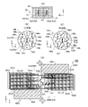
- FIG. 1 is a figure which shows schematic structure of the exposure apparatus which concerns on 1st Embodiment.
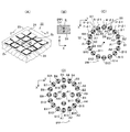
- A is an enlarged perspective view showing a part of mirror elements of an SLM (spatial light modulator)
- B is a diagram showing a polarization state of a light beam incident on the SLM
- C is a distribution of polarization states of an illumination pupil.
- D is a figure which shows another example of distribution of the polarization state of an illumination pupil.
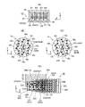
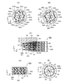
- A is a diagram showing an array of mirror elements of the SLM in FIG.
- (B) is a diagram showing a first optical rotator plate
- (C) is a diagram showing a second optical rotator plate
- (D) is a diagram showing It is a figure which shows a polarization control system.
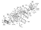
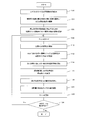
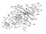
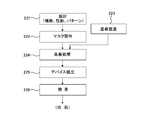
- (A) is a perspective view which shows the principal part of an illumination optical system. It is a flowchart which shows an example of the illumination method and the exposure method.
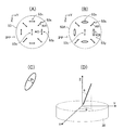
- (A) is a diagram showing an example of a preferred polarization state on the illumination pupil plane
- (B) is a diagram showing an example of a change in the polarization state of FIG. 6
- (C) is a diagram showing an example of elliptical polarization
- (D) is a figure which shows an example of the incident angle with respect to an optical rotator.
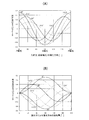
- (A) is a figure which shows an example of the relationship between the polarization direction of the incident light in a rotator, and the Stokes parameter S3 of an emitted light
- (B) is the relationship between the rotation amount of the polarization direction by an rotator, and the Stokes parameter S3 of an emitted light. It is a figure which shows an example. It is a perspective view which shows the principal part of the illumination optical system of a modification.
- (A) is a diagram showing a first optical rotator plate in FIG. 8,
- (B) is a diagram showing a second optical rotator plate,
- (C) is a diagram showing a polarization control system, and
- (D) is a polarization control system.
- FIG. 10A is a diagram showing an array of mirror elements of the SLM in FIG. 10
- FIG. 10B is a diagram showing the polarization state of light incident on the optical rotator plate in FIG. 10
- FIG. 11D is a diagram illustrating a polarization control system in FIG. 10. It is a flowchart which shows the manufacturing process of a semiconductor device.
- FIG. 1 shows a schematic configuration of an exposure apparatus EX according to the present embodiment.
- the exposure apparatus EX includes a projection optical system PL.
- the Z-axis is taken in parallel to the optical axis AX of the projection optical system PL
- the X-axis is taken in a direction perpendicular to the plane of FIG.
- the description will be made by taking the Y axis in a direction parallel to the paper surface.
- the exposure apparatus EX illuminates the pattern surface (here, the lower surface) Ra of the reticle R using a light source 10 that generates exposure illumination light (exposure light) IL and the illumination light IL from the light source 10.
- Illumination optical system ILS and reticle stage RST that moves while holding reticle R are provided.
- the exposure apparatus EX includes a projection optical system PL that forms an image of the pattern of the reticle R on the surface of a semiconductor wafer (hereinafter simply referred to as a wafer) W as a photosensitive substrate, and a wafer that holds and moves the wafer W.
- a stage WST, a main control unit 38 comprising a computer that controls the overall operation of the apparatus, and an illumination control unit 36 that controls the illumination conditions of the illumination optical system ILS under the control of the main control unit 38 are provided. ing.
- the illumination optical system ILS of the present embodiment cooperates with a spatial light modulator (SLM) 22 for controlling the pupil intensity distribution of illumination light, and the spatial light modulator 22, and the illumination pupil of illumination light
- SLM spatial light modulator
- the polarization unit 8 controls the distribution of the polarization state in
- an ArF excimer laser light source that supplies pulsed light having a wavelength of 193 nm is used.
- a KrF excimer laser light source that supplies light with a wavelength of 248 nm a solid-state laser light source (such as a YAG laser or a semiconductor laser), or a harmonic generator for laser light can also be used.
- the illumination light IL emitted from the light source 10 has a polarization state in which linearly polarized light along a certain direction according to the configuration of the light source 10 is a main component.
- a polarization state mainly composed of linearly polarized light along a certain direction is a state in which the ratio of the intensity of the linearly polarized light in that direction to the total light intensity (degree of polarization) is 80% or more. Can do.
- linearly polarized light in a certain direction includes light in a polarization state whose main component is linearly polarized light along that direction.
- the linearly polarized illumination light IL emitted from the light source 10 in the + Y direction is incident on the illumination optical system ILS, and first passes through the beam transmission system 12 to be in a desired polarization state and in a desired cross-sectional shape.
- a light beam is incident on the mirror MR1.
- the beam transmission system 12 adjusts the cross-sectional shape of the incident light, and sets the polarization state of the incident light as a whole, for example, linearly polarized light in the X direction or Z direction, circularly polarized light, or non-polarized light (random polarized light). Eject.
- the beam transmission system 12 can also adjust the degree of polarization of incident light.
- the beam transmission system 12 is a transmission optical system disclosed in US Patent Publication No. 2012/0028197, which can smooth the intensity distribution of light emitted from a light source and guide it to a spatial light modulator. Can be used.
- the illumination light IL incident on the mirror MR1 from the beam transmission system 12 has, as an example, a substantially rectangular cross section 50 elongated in the X direction, as shown in FIG. It shall be linearly polarized.
- the polarization state is also referred to as longitudinal polarization DV
- the polarization state Is also referred to as horizontally polarized light DH.
- illumination light IL of longitudinally polarized light DV enters the mirror MR1 from the beam transmission system 12.
- the illumination light IL of the laterally polarized light DH may be emitted from the beam transmission system 12.
- Illumination light IL emitted from the beam transmission system 12 is reflected obliquely upward (in the ⁇ Y direction and + Z direction) by the mirror MR1 and is reflected on a plurality of mirror elements 24 of the spatial light modulator (hereinafter referred to as SLM) 22.
- SLM spatial light modulator
- Illumination light IL reflected by the plurality of mirror elements 24 in the direction centered on the + Y direction enters the polarization control system 28 via the front lens group 26a, the first optical rotator plate 16, and the rear lens group 26b.
- a first relay optical system 26 is configured by the front lens group 26a and the rear lens group 26b.
- the direction of the optical axis AXI of the illumination optical system ILS is parallel to the Y axis (Y direction) between the beam transmission system 12 and the mirror MR1 and between the SLM 22 and the polarization control system 28, respectively. is there.
- the rear lens group disposed between the first optical rotator plate 16 and the polarization control system 28 is disposed between the first polarization control unit and the second polarization control unit, and the second It may be regarded as a condensing optical system that condenses light from the polarization controller.
- the region (array region) in which each mirror element 24 and the plurality of mirror elements 24 of the SLM 22 are arranged is more than the actual shape. It expresses greatly. Actually, the width of the region where the mirror elements 24 are arranged is considerably smaller than the maximum diameter of the optical system such as the front lens group 26a. For this reason, it may be considered that the region where the mirror elements 24 are arranged is substantially in the vicinity of the optical axis AXI of the illumination optical system ILS.
- the SLM 22 is a main body having a support surface parallel to an array surface P1 which is a plane rotated by a predetermined small angle clockwise around an axis parallel to the X axis with respect to a surface perpendicular to the Y axis. And a plurality of mirror elements 24 that are supported on the supporting surface of the main body 23 and arranged on the arrangement plane P1 in the X direction and in a direction perpendicular to the X direction (substantially in the Z direction) at predetermined intervals and individually controlled. And have.
- the SLM 22 is tilted around two axes orthogonal to each other (may be crossed obliquely) in the array plane P ⁇ b> 1 as the postures of the plurality of mirror elements 24 based on the control signal from the illumination control unit 36.
- a drive unit 25 that individually controls the angles ⁇ x and ⁇ z (see FIG. 2A) is provided.
- the number of arrangements of the mirror elements 24 in the X direction and the direction orthogonal to the X direction is, for example, several tens to several hundreds, for example.
- the mirror elements 24 are, for example, square (or rectangular) and are dense so that the gap is as small as possible. It is arranged. Note that the mirror element 24 does not necessarily have to be square (or rectangular).
- the arrangement plane P1 is assumed to be a plane on which the centers of the plurality of mirror elements 24 are arranged as an example.
- the normal direction of the array plane P1 intersects the optical axis of the light incident on the SLM 22 and the optical axis AXI of the light reflected and emitted from the SLM 22 (parallel to the Y axis in this portion) at the same angle.
- the illumination light IL of longitudinally polarized light DV consisting of parallel light beams reflected by the mirror MR1 is irradiated on the irradiation area 50A (see FIG. 3A) that is substantially rectangular in the X direction on the arrangement plane P1 of the SLM 22.
- the light is incident on the array plane P1 in the state of P-polarized PP.
- the irradiation region 50A is actually set on the array of mirror elements 24.
- the P-polarized light is defined as an incident surface including a light beam incident obliquely on the array surface P1 and a normal line of the array surface P1 passing through the incident point of the light beam.
- each mirror element 24 in the irradiation region 50A enters the relay optical system 26 in the state of longitudinally polarized light DV (P-polarized light with respect to the array plane P1) polarized in the Z direction.
- the illumination light IL may be incident on the arrangement surface P1 of the SLM 22 in the state of S-polarized light SP (which is also laterally polarized light DH).
- the S-polarized light in this case means that the light beam incident obliquely on the array plane P1 is linearly polarized light having a polarization direction in a direction perpendicular to the incident surface.
- the light incident on the array plane P1 in the S-polarized state enters the relay optical system 26 in the state of laterally polarized light DH (S-polarized with respect to the array plane P1) that is reflected in the X direction after being reflected by each mirror element 24.
- each mirror element 24 changes with respect to the direction parallel to the array plane P1, but the amount of change is substantially smaller than the incident angle of the illumination light IL with respect to the array plane P1, so
- light incident as S-polarized light can be considered to be incident as approximately P-polarized light or S-polarized light on each mirror element 24.
- the reflectance and phase are slightly different between the P-polarized light and the S-polarized light with respect to the obliquely incident light beam, and the difference in the reflectance and the like varies depending on the incident angle. .
- the polarization direction of the reflected light may change or the polarization state may change to elliptically polarized light.
- the light incident on the arrangement plane P1 of the SLM 22 is P-polarized light or S-polarized light, and the polarization state of the reflected light is almost the same as that at the time of incidence. Can be controlled with high accuracy to the target distribution.
- each mirror element 24 of the SLM 22 may be continuously changed, but discretely, for example, a plurality of angles (for example, an angle that changes in units of 0.5 degrees in each of two orthogonal axes, etc.) ) May be switched.
- SLM 22 spatial light modulator
- the SLM 22 (spatial light modulator) of the present embodiment for example, European Patent Publication No. 779530, US Pat. No. 5,867,302, US Pat. No. 6,600,591, US Pat. No. 900,915, US Pat. No. 7,295,726, US Pat. No. 7,567,375, US Patent Publication No. 2005/046921, US Patent Publication No. 2008/309901, US Patent Use of a spatial light modulator disclosed in Japanese Patent Publication No.
- Such a spatial light modulator can also be manufactured using, for example, a so-called MEMS (Microelectromechanical Systems) technique.
- MEMS Microelectromechanical Systems
- the light reflected by the plurality of mirror elements 24 of the SLM 22 is a circular flat plate disposed at the position of the pupil plane P ⁇ b> 2 of the relay optical system 26 via the front lens group 26 a of the relay optical system 26.
- the front lens group 26a is set so that its front focal position substantially coincides with the center of the arrangement surface P1 of the SLM 22, and its rear focal position substantially coincides with the center of the pupil plane P2.
- each mirror element 24 The light reflected by each mirror element 24 is incident on the position in the X direction and the Z direction on the pupil plane P ⁇ b> 2 determined according to the inclination angle (posture) around two orthogonal axes of each mirror element 24. For this reason, the light intensity distribution according to the distribution of the individual inclination angles of the plurality of mirror elements 24 of the SLM 22 is variably formed on the entire surface of the optical rotator plate 16 installed on the pupil plane P2.
- the eight-part optical rotator plate 16 is arranged in close contact with each other in the circumferential direction so as to surround the central region 16a and a small circular central region 16a centered on the optical axis AXI.
- the centers of the first and fifth partial regions 16b and 16f are arranged on the ⁇ X direction side along a straight line passing through the optical axis AXI and parallel to the X axis, respectively, and the second and sixth partial regions 16c,
- the center of 16g is arranged along an oblique axis that passes through the optical axis AXI and intersects the X axis counterclockwise at 45 degrees, and the centers of the third and seventh partial regions 16d and 16h are respectively the optical axis AXI.
- the optical rotator plate 16 is an optical element (optical rotator) having individual (same or different) optical rotatory power in each of nine regions including the central region 16a and the partial regions 16b to 16i. It is formed from the optical material which has property.
- a crystal material having optical activity for example, a crystal that is a uniaxial crystal can be used.
- the quartz crystal either a left-rotating left crystal or a right-handing dextrorotatory right crystal can be used.
- the front surface of the optical rotator plate 16 on which the light beam is incident (and hence the rear surface from which the light beam is emitted) is substantially orthogonal to the optical axis AXI, and its crystal optical axis is substantially coincident with the direction of the optical axis AXI (that is, Y is the traveling direction of incident light). Almost coincides with the direction).
- a surface (an installation surface of the optical rotator plate 16) between the front surface and the rear surface of the optical rotator plate 16 is on the pupil plane P2.
- an optical rotatory member In a member made of an optical rotator or an optical material having optical rotatory power (hereinafter referred to as an optical rotatory member), the incident linearly polarized light is rotated by an angle corresponding to the thickness of the optical rotator (optical rotator). It is injected in the state.
- the rotation angle in the polarization direction by the optical rotator (optical rotator) of linearly polarized light is referred to as an angle of rotation (or angle of rotation).
- the optical rotation angle with a sign of + (positive) represents a counterclockwise (counterclockwise) angle with respect to the light traveling direction
- the optical rotation angle with a sign of ⁇ (negative) is It shall represent a clockwise (clockwise) angle with respect to the traveling direction of light.
- an optical rotation angle without a sign in which the rotation direction is not particularly defined means that it may be either a counterclockwise or clockwise direction.
- the thickness of the four partial regions 16c, 16g, 16e, and 16i arranged in the direction of 45 degrees obliquely with respect to the central region 16a and the central region 16a is such that the optical rotation angle of these portions is 0 degree. (Or 0 degrees + n1 ⁇ 180 degrees (n1 is an integer of 0 or more)), that is, the polarization direction of linearly polarized light incident in the + Y direction is set to be emitted as it is.
- the luminous flux of longitudinally polarized light DV polarized in the Z direction is incident on the optical rotator plate 16 from the SLM 22, longitudinally polarized light is emitted from the central region 16a and the partial regions 16c, 16g, 16e, and 16i. DV light is emitted.
- the polarization direction of the emitted light is the same regardless of whether the optical rotation angle is ⁇ a or “ ⁇ a + n1 ⁇ 180 degrees (n1 is an arbitrary integer greater than or equal to 0)”, and therefore the central region 16a and the partial regions 16c and 16g. , 16e, 16i may be set so that the optical rotation angle is 180 degrees, 360 degrees,.
- the central region 16a and the partial regions 16c, 16g, 16e, and 16i only need to have a rotation angle of the polarization direction of 0 degrees. Therefore, the central region 16a and the partial regions 16c, 16g, 16e, and 16i are simply subjected to light as they are.
- a glass substrate that does not transmit optical rotation may be disposed, or may be a window (opening).
- the thickness of the pair of partial regions 16b and 16f sandwiching the central region 16a in the X direction and the pair of partial regions 16d and 16h sandwiching the Z direction is an example of the optical rotation angle of those portions.
- the polarization direction of light incident as longitudinally polarized light DV is 45 degrees clockwise with respect to the Z axis.
- clockwise 45-degree polarized DSB an example of the polarization direction of the incident light is indicated by a dotted arrow, and the polarization direction when the incident light is emitted is indicated by a solid line. It is represented by an arrow.
- the optical rotator plate 16 When the polarization direction of the light incident on the optical rotator plate 16 is laterally polarized light DH parallel to the X direction, the light that has passed through the partial regions 16b, 16f, 16d, and 16h is 45 in the counterclockwise direction about the Z axis. In this case, the optical rotator plate 16 is effective as will be described later.
- the optical rotation angles in the partial areas 16b, 16f, 16d, and 16h may be set to “ ⁇ 45 degrees + (n2 + 1) 180 degrees” counterclockwise (the same applies hereinafter).
- the optical rotator plate 16 is obtained by processing the central region 16a and the partial regions 16b to 16i of a disk-shaped member made of a crystal material having optical activity into a thickness corresponding to each optical rotation angle by etching or the like. It can be manufactured.
- the optical rotator plate 16 can be thickened, so that the optical rotator plate 16 may be easily manufactured and supported.
- the central region 16a and the oblique partial regions 16c, 16g, 16e, and 16i may have the same thickness, and the other four partial regions 16b, 16f, 16d, and 16h have the same thickness. Good.
- the central region 16a and the oblique partial regions 16c, 16g, 16e, and 16i are cut out from the same optical rotation member (or glass substrate) having a predetermined thickness, and the other partial regions 16b, 16f, 16d,
- the optical rotator plate 16 may be formed by cutting 16h from the same optical rotation member having a predetermined thickness and bonding the formed central region 16a and partial regions 16b to 16i together by bonding or the like. Further, the central region 16a and the partial regions 16c, 16g, 16e, and 16i are used as transparent portions, and the other partial regions 16b, 16f, 16d, and 16h are supported from the outside, and substantially the same operation as the optical rotator plate 16 is achieved.
- An optical member may be formed and used instead of the optical rotator plate 16.
- the optical rotation angle in the partial regions 16b, 16f, 16d, and 16h of the optical rotator plate 16 may be set to “45 degrees + n2 ⁇ 180 degrees” (n2 is an integer of 0 or more) (hereinafter the same). Further, the optical rotation angle (and thus the rotation angle of the polarization direction) in the partial areas 16b, 16f, 16d, and 16h is set to an arbitrary angle within the range of 20 degrees to 70 degrees (+ n2 ⁇ 180 degrees) clockwise or counterclockwise. It is also possible (details are described later).
- the polarization direction of the incident light is usually the longitudinal polarization DV or the lateral polarization DH
- the polarization direction of the incident light is changed using, for example, a half-wave plate instead of the optical rotator plate 16.
- An optical member for conversion can also be used.
- the illumination light IL that forms a light intensity distribution on the pupil plane P2 and passes through the first optical rotator plate 16 passes the X direction in the longitudinal direction to the polarization control system 28 via the rear lens group 26b of the relay optical system 26.
- the incident light is incident on a rectangular cross section 50B (see FIG. 3D).
- the polarization control system 28 (first polarization control unit) includes first, second, third, and third rectangular plate-shaped plates that are larger than the cross-section 50B formed from an optical material having optical rotation.
- the fourth optical rotation member 30A, 30B, 30C, 30D, and the optical rotation member 30A-30D are individually provided with a drive unit DR1 that moves across the illumination optical path.
- the optical rotation members 30A to 30D are arranged in the + Y direction in the order of the optical rotation members 30D, 30C, 30B, and 30A.
- the arrangement order is arbitrary.
- a crystal material having optical activity for example, quartz (left quartz or right quartz) can be used as with the optical rotator plate 16.
- Each of the optical rotation members 30A to 30D can also be called an optical rotator.
- the optical rotatory members 30A to 30D can be manufactured by processing a crystal material having optical rotatory power to a thickness corresponding to each optical rotation angle.
- each of the optical rotation members 30A to 30D are substantially orthogonal to the optical axis AXI, and the crystal optical axes thereof are substantially coincident with the direction of the optical axis AXI (that is, incident). And substantially coincides with the Y direction which is the traveling direction of light).
- a surface between the central optical rotation members 30C and 30B (or a surface between the front surface of the optical rotation member 30D and the rear surface of the optical rotation member 30A, or a surface in the vicinity of these surfaces) may be used.
- the installation surface P3 is 30D
- the installation surface P3 is substantially perpendicular to the optical axis AXI. Since the thickness of the optical rotation members 30A to 30D is actually considerably smaller than the focal length of the rear lens group 26b, etc., the optical rotation members 30A to 30D can be regarded as being almost at the position of the installation surface P3. it can.
- the rear focal position of the front lens group 26a of the relay optical system 26 and the front focal position of the rear lens group 26b substantially coincide with each other, and the rear focal position of the rear lens group 26b is substantially the optical rotation member 30A ⁇ . It is located at the center of the installation surface P3 of 30D. Accordingly, the installation surface P3 and the arrangement surface P1 of the SLM 22 are substantially conjugate with respect to the relay optical system 26, and the rectangular cross section 50B of the illumination light IL in FIG. 3D is an arrangement surface of the SLM 22 in FIG. It is almost conjugate with the irradiation region 50A of the illumination light IL in P1.
- the drive unit DR1 of the polarization control system 28 translates the optical rotation member 30A in the Z direction (short side direction) as an example with respect to the cross section 50B of the illumination light IL, and the other three.
- the optical rotatory members 30B to 30D are translated in the X direction (long side direction) independently of each other.
- the edge portion in the Z direction (movement direction) in the cross section 50B of the optical rotation member 30A is substantially parallel to the edge portion in the Z direction (linear shape substantially parallel to the X axis) of the outline of the cross section 50B, and the optical rotation member 30B.
- the edge portion in the X direction (movement direction) in the cross section 50B of ⁇ 30D is substantially parallel to the edge portion in the X direction of the contour of the cross section 50B (a straight line substantially parallel to the Z axis).
- the drive unit DR1 includes four actuators for individually moving the optical rotation members 30A to 30D and four encoders for individually detecting the movement amounts of the optical rotation members 30A to 30D.
- the optical rotation members 30A to 30D are moved based on the control signal from.
- the support and drive mechanism of the optical rotation members 30A to 30D can be simplified.
- the plane conjugate to the arrangement plane P1 is also slightly different from the plane perpendicular to the optical axis. It may be inclined.
- the installation surface P3 of the polarization control system 28 is set to be inclined along a plane conjugate to the arrangement plane P1, and the optical rotation members 30A to 30D are moved along the inclined surface. You may do it.
- the optical rotator plate 16 may be installed along the inclined plane.
- a portion where the optical rotatory members 30A to 30D do not overlap (through portions) is the first partial region C1, a portion where only the optical rotatory member 30B is present, the second partial region C2, and the optical rotatory members 30B, 30C.
- a portion where only the optical rotation members 30B to 30D overlap, a portion where only the optical rotation members 30B to 30D overlap, a portion where only the optical rotation member 30A overlaps, a portion where only the optical rotation member 30A overlaps, and a portion where only the optical rotation members 30A and 30B overlap Is a sixth partial region C6, a portion where only the optical rotation members 30A to 30C overlap is called a seventh partial region C7, and a portion where all of the optical rotation members 30A to 30D overlap is called an eighth partial region C8.
- the light incident on the partial areas C1 to C8 is continuously subjected to an optical rotation action by the optical rotatory members 30A to 30D arranged in the partial areas.
- the second partial region C2 is a region in which, for example, incident light of longitudinally polarized light DV is subjected to an optical rotation action only once by the optical rotation member 30B. This is a region that continuously receives the optical rotation.
- the polarization direction of the light incident on the cross section 50B is 45-degree polarized DSB (or DSA) in addition to longitudinally polarized light DV (or laterally polarized light DH).
- DSA longitudinally polarized light DV
- the cross section 50B of the illumination light IL in the polarization control system 28 and the irradiation region 50A of the illumination light IL for the SLM 22 in FIG. 3A are conjugate. Therefore, the regions in the irradiation region 50A conjugate with the eight partial regions C1, C2, C3, C4, C5, C6, C7, and C8 in the cross section 50B are respectively represented as partial array regions D1, D2, D3, and D3. Called D4, D5, D6, D7, and D8.
- the area ratio of the eight partial regions C1 to C8 (and thus the ratio of the cross-sectional area of light passing through the partial regions C1 to C8) can be changed in a wide range. .
- the area ratio of the partial regions C1 to C8 is changed, the area ratio of the partial array regions D1 to D8 in the SLM 22 (and thus the ratio of the number of mirror elements 24 in these array regions) is also changed at the same rate. .
- the illumination optical system ILS of the present embodiment has a polarization state distribution at the illumination pupil that is 180 degrees ( ⁇ (rad) with respect to the polarization direction of light, for example, with reference to longitudinally polarized light DV (or laterally polarized light DH). )) Of 1 / N (N is an integer of 2 or more), and the angle ⁇ 1 can be set as a unit.
- N is an integer of 2 or more
- the angle ⁇ 1 can be set as a unit.
- N is an integer of 2 or more
- N 4
- N 8
- the directions rotated by degrees, 22.5 degrees, 45 degrees, 67.5 degrees, 90 degrees, 112.5 degrees, 135 degrees, and 157.5 degrees are directions A1, A2, A3, and A4 in FIG. , A5, A6, A7, A8.
- a polarization state with a very high degree of freedom can be set by setting the polarization directions of a plurality of local regions in the illumination pupil to any combination of directions A1 to A8.
- the thickness of the optical rotation members 30A, 30B, 30C, and 30D is the light incident in the + Y direction, respectively.
- n3, n4, n5, and n6 are each an integer of 0 or more, and n3 to n6 may be different from each other.
- the optical rotation angle in the optical rotation member 30A is 90 degrees counterclockwise, and the optical rotation angles in the optical rotation members 30B to 30D are commonly 22.5 degrees counterclockwise.
- the optical rotation angle in the optical rotation member 30A is 270 degrees counterclockwise
- the optical rotation angles in the optical rotation members 30B to 30D are commonly 205.5 degrees counterclockwise.
- the polarization direction of the emitted light is the same.
- the optical rotation angle is set between the optical rotation members 30A to 30D so that the optical rotation angle is set counterclockwise in the optical rotation members 30A and 30C, and the optical rotation angle is set clockwise in the optical rotation members 30B and 30D. (Clockwise) may be different.
- the integers n3 to n6 that define the optical rotation angle are increased, the optical rotation members 30A to 30D can be thickened, and thus the optical rotation members 30A to 30D may be easily manufactured and supported.
- the angle of the optical rotation member when the optical rotation angle of the optical rotation member is ⁇ a counterclockwise or clockwise, the angle includes “ ⁇ a + n ⁇ 180 degrees” (n is an integer of 0 or more).
- the polarization direction of the light incident on the partial areas C1 to C8 changes by the sum of the optical rotation angles by the optical rotation members 30A to 30D in the partial areas.
- the polarization direction after rotating at an angle ⁇ a is the same as the polarization direction after rotating at an angle “ ⁇ a + na ⁇ 180 degrees” (na is an integer). For this reason, in FIG.
- the polarization state having the polarization direction changed by ⁇ 45 degrees with respect to the longitudinal polarization DV is 45 degree polarization DSA and DSB
- the polarization state having the polarization direction changed by ⁇ 22.5 degrees with respect to the longitudinal polarization DV is 45 degree polarization DSA and DSB
- the polarization state having the polarization direction changed by ⁇ 22.5 degrees with respect to the 22.5 degree polarizations DV1 and DV2 and the lateral polarization DH will be referred to as 22.5 degree polarizations DH1 and DH2.
- the polarization state of the illumination light after passing through the partial regions C1, C2, C3, C4, C5, C6, C7, and C8 in the cross section 50B is DV, DV1, DSA, DH2, DH, DH1, DSB, respectively.
- the polarization directions of these polarization states DV to DV2 correspond to the polarization directions A1 to A8 in FIG.
- the partial areas C1 to C8 in the cross section 50B are conjugate with the partial array areas D1 to D8 in the irradiation area 50A of the SLM 22, the polarization directions of the light after passing through the partial areas C1 to C8 are different from each other.
- the light reflected by the eight partial array regions D1 to D8 having variable area ratios in the irradiation region 50A of the SLM 22 is linearly polarized light having different polarization directions.
- the angle of one or a plurality of mirror elements 24 in the partial array regions D1 to D8 the light intensity distribution in the illumination pupil is a distribution having eight polarization directions in an arbitrary arrangement. Can be set.
- the optical rotation angle at 30D can be arbitrarily combined. For example, even if the optical rotation angles in the optical rotation members 30A, 30B, 30C, and 30D are respectively set to 22.5 degrees, 90 degrees, 45 degrees, and 90 degrees in the counterclockwise direction, the polarization directions of the light after passing through these are 8 You can set the direction. Furthermore, the optical rotation angles in the optical rotation members 30A, 30B, 30C, and 30D may be 90 degrees, 22.5 degrees, 22.5 degrees, and 22.5 degrees clockwise.
- all of the optical rotation members 30 ⁇ / b> B, 30 ⁇ / b> C, 30 ⁇ / b> D and the like are arranged on the downstream side of the mirror element 24. For this reason, the illumination light with which the mirror element 24 is irradiated can be only P-polarized light or S-polarized light with respect to the mirror element 24. Therefore, the polarization generated when the mirror element 24 is irradiated with light that is neither P-polarized light nor S-polarized light State fluctuation can be prevented.
- the polarization control system 28 is used to form the distribution of the polarization state in the illumination pupil.
- the optical rotation members 30A to 30D constituting the polarization control system 28 have, for example, a crystal optical axis parallel to the optical axis AXI.
- linearly polarized light incident obliquely on the optical rotator may be emitted as elliptically polarized light depending on the incident angle and the polarization direction at the time of incidence.
- the above-described first optical rotator plate 16 is used to suppress elliptical polarization (decrease in the degree of polarization) of light obliquely incident on the optical rotation members 30A to 30D (details will be described later).
- the array of mirror elements 24 of the SLM 22 is actually disposed near the front focal position of the front lens group 26a, and the first optical rotator plate 16 is substantially behind the front lens group 26a. It is arranged on the side focal plane (pupil plane P2 of the relay optical system 26). For this reason, the illumination light IL (typically showing three lights IL1, IL2, and IL3) that is reflected by the array of mirror elements 24 of the SLM 22 and enters the optical rotator plate 16 via the front lens group 26a is substantially light. It is parallel to the axis AXI and substantially perpendicularly enters the entire surface of the optical rotator plate 16.
- the optical rotator plate 16 is formed by using an optical rotator having a crystal optical axis parallel to the optical axis AXI, the optical rotator plate 16 is not substantially elliptically polarized.
- the light IL1 in FIG. 1 is different from the light IL1 in FIG. 4 described later.
- the illumination light IL that has passed through the polarization control system 28 enters the mirror MR2 via the front lens group 32a, the second optical rotator plate 18, and the rear lens group 32b.
- a second relay optical system 32 is configured by the front lens group 32a and the rear lens group 32b.
- a polarization unit 8 for controlling the polarization state distribution of the illumination pupil is constituted by the optical rotator plate 16, the polarization control system 28, and the optical rotator plate 18.
- the illumination light IL that has passed through the polarization control system 28 passes through the front lens group 32a of the relay optical system 32, and the second plate-shaped second plate 8 arranged at the position of the pupil plane P4 of the relay optical system 32.
- the light enters the divided optical rotator plate 18 (third polarization controller).
- the front lens group 26a is set so that its front focal position substantially coincides with the center of the installation surface P3 of the polarization control system 28, and its rear focal position substantially coincides with the center of the pupil plane P4.
- the pupil plane P2 on which the first optical rotator plate 16 is installed and the pupil plane P4 on which the second optical rotator plate 18 is installed are conjugate with respect to the optical system including the lens group 26b and the lens group 32a. is there. Therefore, a distribution obtained by inverting the light intensity distribution formed on the pupil plane P2 over the entire surface of the optical rotator plate 18 installed on the pupil plane P4, that is, a distribution of individual inclination angles of the plurality of mirror elements 24 of the SLM 22.
- the corresponding light intensity distribution is variably formed.
- first and fifth partial regions 18b and 18f and the third and seventh partial regions 18d and 18h are arranged so as to sandwich the central region 18a in the X direction and the Z direction, respectively, and the second and sixth portions
- the regions 18c and 18g and the fourth and eighth partial regions 18e and 18i are respectively arranged so as to sandwich the central region 18a from the oblique 45 degree direction.
- the optical rotator plate 18 is an optical element (optical rotation) having a predetermined optical rotation (same or different) in each of nine regions including the central region 18 a and the partial regions 18 b to 18 i. As an example, it is made of an optical material having optical rotation as a whole.
- a crystal material having optical activity for example, a uniaxial crystal (left crystal or right crystal) can be used.
- the front surface and the rear surface on which the light beam of the optical rotator plate 18 enters and exits are substantially orthogonal to the optical axis AXI, and the crystal optical axis thereof substantially coincides with the direction of the optical axis AXI.
- a surface (an installation surface of the optical rotator plate 18) between the front surface and the rear surface of the optical rotator plate 18 is on the pupil plane P4.
- the optical rotation angles (rotational angles of the polarization direction of incident light) in the central region 18a and the eight partial regions 18b to 18i of the second optical rotator plate 18 are respectively corresponding (conjugated) to the first optical rotator plate 16. It is set so as to cancel the optical rotation angles in the central region 16a and the partial regions 16b to 16i. That is, if the optical rotation angle in a certain region (for example, the partial region 16f) of the first optical rotator plate 16 is ⁇ a clockwise, the optical rotation angle in the corresponding region (for example, the partial region 18f) of the second optical rotator plate 18 is It becomes ⁇ a counterclockwise.
- the optical rotation angle in the central region 16a of the first optical rotator plate 16 and the four partial regions 16c, 16g, 16e, and 16i in the oblique 45 degree direction is 0 degree
- the central region 16a is in the X direction
- the optical rotation angles in the four partial regions 16b, 16f and 16d, 16h sandwiched in the Y direction are set to 45 degrees ( ⁇ 45 degrees) clockwise.
- the optical rotation angle in the central region 18a of the second optical rotator plate 18 and the four partial regions 18c, 18g, 18e, and 18i in the oblique 45 degree direction is 0 degree
- the central region 18a is sandwiched in the X and Y directions.
- the optical rotation angles in the four partial regions 18b, 18f and 18d, 18h are set to 45 degrees (+45 degrees) counterclockwise. As shown in FIG. 3C, for example, when light of longitudinally polarized light DV enters the optical rotator plate 18, the light that has passed through the central region 18a remains the vertically polarized light DV, and the light that has passed through the partial region 18f is left Around 45 degree polarization DSA.
- the optical rotator plate 18 can be manufactured in the same manner as the optical rotator plate 16.
- the polarization direction is returned counterclockwise by the angle ⁇ a after passing through the central region 18a or the partial regions 18b to 18i of the plate 18, and the state is the same as when the polarization direction of the optical rotator plate 16 is not rotated.
- the polarization state of the illumination light IL incident on the optical system after the optical rotator plate 18 is the same as the polarization state when the two optical rotator plates 16 and 18 are not present. Therefore, in FIG.
- the longitudinally polarized light DV (or the laterally polarized light DH) is obtained as in the case where the optical rotator plate 16 is not present. However, it is assumed that the light is incident. In this way, the action of the second optical rotator plate 18 cancels (compensates) the change in the polarization direction of the illumination light IL by the first optical rotator plate 16.
- the installation surface of the second optical rotator plate 18 (substantially the pupil plane P4) and the installation surface of the first optical rotator plate 16 (substantially the pupil plane P2) are substantially conjugate and rotate through the front lens group 32a.
- the illumination light IL incident on the daughter plate 18 is also substantially perpendicularly incident on the entire surface of the optical rotator plate 18. For this reason, even if the optical rotator plate 18 is formed using an optical rotator having a crystal optical axis parallel to the optical axis AXI, the optical rotator plate 18 is not substantially elliptically polarized.
- the illumination light IL that has passed through the optical rotator plate 18 is reflected by the mirror MR2 in the direction centered on the ⁇ Z direction through the lens group 32b, and then the microlens array (through the condensing optical system 33). Or it may be a fly-eye lens).
- the second relay optical system 32 forms a surface P6 that is substantially conjugate with the installation surface P3 of the polarization control system 28 (and thus the arrangement surface P1 of the SLM 22).
- the lens group 32b and the condensing optical system 33 set the pupil plane P4 (and hence the pupil plane P2) and the incident plane P5 of the microlens array 34 to be optically conjugate.
- the illumination light IL that has passed through the array of mirror elements 24 of the SLM 22 has a light intensity distribution similar to the light intensity distribution formed on the pupil plane P2 on the incident surface P5 of the microlens array 34, and the polarization unit 8 Forming a light intensity distribution having a polarization state distribution controlled by.
- the microlens array 34 is an optical element composed of microlenses having a large number of positive refracting powers, for example, which are arranged vertically and horizontally and densely. It can be formed by forming.
- the microlens array is a wavefront division type optical integrator similar to the fly-eye lens in that the lens elements are arranged vertically and horizontally.
- a rear focal plane of the microlens array 34 or a plane in the vicinity thereof becomes an illumination pupil plane IPP, and an illumination pupil is formed on this plane.
- the linearly polarized light in the Y direction corresponds to the longitudinally polarized light DV
- the linearly polarized light in the X direction corresponds to the laterally polarized light DH.
- An illumination aperture stop having an opening (light transmission part) having a shape corresponding to a secondary light source to be described later may be disposed at or near the illumination pupil plane IPP.
- the rectangular minute refracting surface as the unit wavefront dividing surface in the microlens array 34 is similar to the shape of the illumination field (illumination region) to be formed on the reticle R (and thus the shape of the exposure region to be formed on the wafer W). Rectangular shape.
- a cylindrical micro fly's eye lens can be used as the microlens array 34. The configuration and operation of the cylindrical micro fly's eye lens are disclosed in, for example, US Pat. No. 6,913,373.
- the overall light intensity distribution formed on the incident surface P5 of the microlens array 34 and the overall light intensity distribution of the entire secondary light source on the illumination pupil plane IPP. shows a high correlation.
- the light intensity distribution on the incident surface P5 of the microlens array 34 and the surfaces optically conjugate with the incident surface P5 can also be substantially referred to as pupil intensity distribution.
- the relay optical systems 26 and 32, the condensing optical system 32, and the microlens array 34 constitute a distribution forming system that forms a pupil intensity distribution on the illumination pupil IPP immediately after the microlens array 34 based on the light beam that has passed through the SLM 22. ing.
- the first lens group 46a of the condensing optical system 32 and the microlens array 34, or the condensing optical system 32, the microlens array 34, the condenser optical system 42, and the imaging optical system 46 is connected via the first polarization control system.
- the light from the SLM 22 may be regarded as a distribution forming optical system that distributes the light to the illumination pupil of the illumination optical system.
- the illumination light IL incident on the microlens array 34 is two-dimensionally divided by a large number of microlenses and incident on the illumination pupil plane IPP.
- the illumination pupil plane IPP has substantially the same light intensity distribution as that formed on the incident plane P5.
- a secondary light source (pupil intensity distribution as a substantial surface light source made up of a large number of small light sources) having a light intensity distribution and substantially the same polarization state distribution is formed.
- the light beam from the secondary light source formed on the illumination pupil plane IPP illuminates the reticle blind 44 as an illumination field stop via the condenser optical system 42 in a superimposed manner.
- the light beam that has passed through the rectangular opening (light transmitting portion) of the reticle blind 44 is condensed by the second lens group 46b through the first lens group 46a, and the pattern of the reticle R on which a transfer pattern is formed.
- the illumination area of the surface Ra (the lower surface here) is illuminated in a superimposed manner.
- the imaging optical system 46 including the lens groups 46 a and 46 b forms an image of the rectangular opening of the reticle blind 44 on the pattern surface Ra of the reticle R.
- An illumination optical system ILS is configured including the imaging optical system 46.
- the pattern surface Ra (irradiated surface) of the reticle R is an optical Fourier transform surface with respect to the illumination pupil plane IPP by the condenser optical system 42 and the imaging optical system 46 of the illumination optical system ILS.
- the pupil intensity distribution is a light intensity distribution (luminance distribution) on the illumination pupil plane IPP or a plane optically conjugate with the illumination pupil plane IPP.
- the illumination light IL transmitted through the illumination area of the reticle R held on the reticle stage RST is exposed to the surface of the wafer W held on the wafer stage WST via the projection optical system PL (an area conjugate with the illumination area). Then, an image of the reticle pattern is formed.
- the pupil plane of the projection optical system PL (a plane conjugate with the entrance pupil) is conjugate with the illumination pupil plane IPP, and an aperture stop AS is installed at a position near or in the pupil plane of the projection optical system PL.
- the wafer W includes a substrate in which a photoresist (photosensitive agent) is applied to a thickness of about several tens to 200 nm on the surface of a semiconductor disk-shaped base material such as silicon.
- the exposure apparatus EX of the present embodiment is a liquid immersion type
- an apparatus (not shown) that supplies and recovers liquid as disclosed in, for example, US Patent Application Publication No. 2007/242247, etc.
- a liquid that transmits the illumination light IL is supplied to a local region between the lens at the tip of the projection optical system PL and the wafer W.
- reticle stage RST is placed on an upper surface of a reticle base (not shown) so as to be movable at least in the XY plane. At least a two-dimensional position of the reticle stage RST is measured by a laser interferometer (not shown).
- the main controller 38 Based on this measurement information, the main controller 38 detects the position of the reticle stage RST via a drive system DRR including a linear motor and the like. Control the speed. Wafer stage WST is placed on the upper surface of a base member (not shown) so as to be movable at least within the XY plane. At least a two-dimensional position of wafer stage WST is measured by a laser interferometer or an encoder (not shown). Based on this measurement information, main controller 38 of wafer stage WST passes through drive system DRW including a linear motor and the like. Control position and speed.
- the exposure apparatus EX of the present embodiment based on the illumination light IL via the illumination optical system ILS and the projection optical system PL, determines the pupil intensity distribution and the polarization state on the illumination pupil plane IPP or the pupil plane of the projection optical system PL.
- a measuring device 40 for measuring the distribution is provided.
- the measurement device 40 includes a first measurement unit that measures the pupil intensity distribution and a second measurement unit that measures the distribution of the polarization state (for example, a polarization state represented by a Stokes parameter or a Jones matrix).
- the measurement result of the measuring device 40 is supplied to the main control device 38.
- a measurement device similar to the measurement device 40 may be provided on the reticle stage RST so that the pupil intensity distribution and the polarization state distribution of only the illumination optical system ILS can be measured.
- a measurement apparatus that can be used as a pupil intensity distribution measurement unit is disclosed in, for example, US 2010/0020302.
- the wafer W is collectively exposed or scanned through the projection optical system PL while the reticle R is illuminated with the illumination light IL from the illumination optical system ILS.
- the image of the pattern of the reticle R is exposed on all shot areas of the wafer W.
- the Y direction in FIG. 1 can be set to the scanning direction of the reticle R and the wafer W.
- each of the optical rotation members 30A to 30D constituting the polarization control system 28 is, for example, a crystal plate (crystal rotator) as a uniaxial crystal having a crystal optical axis parallel to the optical axis AXI
- the crystal plate is It acts purely as an optical rotator for light incident perpendicularly to it, and emits incident linearly polarized light as linearly polarized light whose polarization direction is rotated by a target optical rotation angle.
- FIG. 6A shows an example of a pupil intensity distribution 53 having a preferable polarization state distribution on the illumination pupil plane IPP.
- the distribution of the polarization direction in the pupil intensity distribution 53 is the X direction in the central portion 53c centered on the optical axis, and the circumferential direction AC (longitudinal polarization DV or horizontal in the regions 53x and 53y adjacent to the central portion in the X direction and Y direction.
- the region 53s adjacent to the central portion in the oblique direction is the radial direction AR (45-degree polarized light).
- each of the optical rotation members 30A to 30D having an optical Fourier transform relationship with respect to the illumination pupil plane IPP is a quartz plate, and the polarization direction of incident light incident thereon is uniformly vertical polarization DV (polarization direction). Is in the Y direction), as shown in FIG. 6B, in the regions 53x and 53y in the X direction and the Y direction, the polarization state is changed to elliptically polarized ACE.
- the light incident on the central portion 53c in FIG. 6B is the light that is almost perpendicularly incident on the quartz plate, and the region 53x.
- the light incident on (or 53y) is light that is inclined in the X direction (or the direction corresponding to the Y direction) on the quartz plate and is incident as S-polarized light (or P-polarized light) and enters the region 53s.
- Incident light is inclined in a direction substantially intersecting the X-axis (or the direction corresponding to the Y-axis) with the crystal plate at about 45 degrees and inclined at about 45 degrees with respect to the incident surface (Y direction).
- the light was polarized. Therefore, light incident in a P-polarized or S-polarized state obliquely with respect to the quartz plate changes to elliptically polarized ACE at the time of emission.
- the degree of elliptically polarized light (for example, the characteristic represented by the ratio of the short radius b to the long radius of the locus of the electric vector of elliptically polarized light shown in FIG. 6C) is four Stokes parameters S0, S1, S2. , S3 among the Stokes vectors.
- the Stokes parameters S0 and S3 are defined as follows, and when the Stokes parameter S0 is normalized so that the Stokes parameter S0 is 1, the value of the Stokes parameter S3 (hereinafter also referred to as parameter S3) is in the range of ⁇ 1 to +1. Obviously, the Stokes parameter S0 is normalized so that the Stokes parameter S0 is 1, the value of the Stokes parameter S3 (hereinafter also referred to as parameter S3) is in the range of ⁇ 1 to +1. Become.
- S0 total intensity of luminous flux (3)
- FIG. 6D shows a quartz plate (quartz rotator) 30 on which light is incident at an incident angle ⁇ .
- the Z axis is set parallel to the optical axis of the crystal crystal which is a uniaxial crystal, and the orthogonal coordinate system of the plane perpendicular to the Z axis is the X axis and the Y axis.
- the light incident surface (upper surface) and the light exit surface (lower surface) of the quartz plate 30 coincide with a plane (XY plane) perpendicular to the optical axis.
- FIGS. 7A and 7B show emission light (transmission) when linearly polarized light having an incident angle ( ⁇ ) of 10 degrees and a wavelength of 193 nm is obliquely incident on the quartz plate 30 of FIG. 6C.
- Light S3 parameter. Note that since the crystal is a uniaxial crystal, the polarization state of the emitted light does not change depending on the incident direction of the incident light (angle ⁇ in FIG. 6D). Further, the horizontal axis of FIG. 7A is “polarization direction (°) of linearly polarized incident light”, and the vertical axis is the S3 parameter of emitted light (transmitted light).
- ⁇ incident angle
- the six curves have rotation amounts (rotation angles) in the polarization direction of 22.5 degrees, 45 degrees, 67.5 degrees, 90 degrees, 112.5 degrees, and 135 degrees, respectively. It represents the S3 parameter of the emitted light determined for the optical rotator of thickness.
- the state where the value of the horizontal axis (polarization direction of incident light of linearly polarized light) in FIG. 7A is 0 degrees and 180 degrees is a so-called P-polarized state, and the value of 90 degrees is a so-called S-polarized light. It is a state. From the curve in FIG. 7A, the polarization direction of the linearly polarized light incident on the quartz crystal plate 30 (optical rotator) is in the vicinity of 0 degree or 180 degrees (approximately P-polarized light) and in the vicinity of 90 degrees (approximately S-polarized light). In particular, when the polarization direction is rotated by 90 degrees, it can be seen that the absolute value of the S3 parameter of the emitted light is large, that is, the degree of elliptical polarization is large.
- the polarization direction of the linearly polarized light incident on the quartz plate 30 is about 45 degrees or 135 degrees ( ⁇ 45 degrees) with respect to the incident surface, even if the polarization rotation is performed at an arbitrary angle, the S3 of the emitted light It can be seen that the absolute value of the parameter is relatively small, that is, the degree of elliptical polarization is small.
- the horizontal axis of FIG. 7B is “the amount of rotation in the polarization direction (rotation angle) (°) by the optical rotator (crystal plate 30)”, that is, the horizontal axis corresponds to the thickness of the optical rotator,
- the vertical axis represents the S3 parameter of the emitted light (transmitted light).
- the seven curves in FIG. 7B indicate that the “polarization direction of the incident linearly polarized light” is 0 degree (P-polarized light), 22.5 degrees, 45 degrees, 67.5 degrees with respect to the incident surface, respectively. It represents the value of the S3 parameter of the emitted light obtained for the cases of 90 degrees (S-polarized light), 112.5 degrees, and 135 degrees.
- S-polarized light when light close to P-polarized light or S-polarized light is incident on the rotator, the absolute value of the S3 parameter of the emitted light is large when the rotation angle in the polarization direction is close to 90 degrees, and elliptical polarization is achieved. It can be seen that the degree of is large.
- the polarization state of the linearly polarized light incident on the optical rotator is a state that is neither P-polarized light nor S-polarized light, for example, a state polarized in a direction inclined by 45 degrees or 135 degrees on the incident surface (hereinafter referred to as 45-degree polarized light) or Assuming a state close to 45 degree polarization, it can be seen that the absolute value of the S3 parameter is relatively small and the degree of elliptical polarization is small even after rotation of the polarization direction at an arbitrary angle by the optical rotator.
- FIG. 4 shows a main part of the illumination optical system ILS in FIG.
- the array (irradiation region 50A) of the mirror elements 24 of the SLM 22 and the region (cross section 50B) where the illumination light IL of the polarization control system 28 is incident are substantially near the optical axis AXI of the illumination optical system.
- the lights IL1, IL5, IL4, and IL8 reflected by the mirror elements 24A, 24B, 24G, and 24H are in the state of longitudinally polarized light DV through the front lens group 26a, respectively.
- the light is incident on the partial region 16e in the oblique direction, the partial region 16d in the Z direction, the central region 16a, and the partial region 16b in the X direction.
- the reflected light from the plurality of mirror elements 24 is independent from each other according to the inclination angle of the mirror element 24. It can be incident on any of 16 positions, and thus on any position of the illumination pupil plane IPP.
- the light IL4 and IL1 that have passed through the central region 16a (rotation angle is 0 degree) and the oblique partial region 16e (rotation angle is 0 degree) of the optical rotator plate 16 remain as the longitudinally polarized light DV.
- the light enters the partial areas C4 and C1 of the polarization control system 28 through the lens group 26b.
- the light IL4 that has passed through the central region 16a enters the partial region C4 through the rear lens group 26b substantially perpendicularly, elliptical polarization is not performed after passing through the optical rotation members 30B to 30D in the partial region C4. Does not occur.
- the light is reflected by the mirror element 24 at an arbitrary position in the SLM 22 and passes through the central region 16a to a corresponding position of the polarization control system 28 (a position conjugate with the mirror element 24 in the cross section 50B, and so on). Since the incident light is also substantially perpendicularly incident on the cross section 50B, elliptical polarization does not occur.
- the incident surface is substantially the ZY plane (a plane parallel to the optical axis AXI (Y axis) and the Z axis). It is a surface rotated 45 degrees counterclockwise toward (+ Y direction), and the polarization direction of the light IL1 of the vertically polarized light DV that has passed through the partial region 16e is approximately 45 degrees with respect to its incident surface (polarization direction of P-polarized light). It becomes the direction which crosses at. Accordingly, the light IL1 is incident on the partial region C1 of the polarization control system 28 with a polarization direction changed by approximately 45 degrees from the direction of P-polarization or S-polarization.
- the mirror element 24 is reflected by the mirror element 24 at an arbitrary position in the SLM 22 and passes through the partial region 16e (or the other partial regions 16c, 16g, 16i in the other 45 degrees direction in FIG.
- the light incident on the corresponding position of the polarization control system 28 by DV is also polarized in the direction crossing the cross section 50B at approximately 45 degrees with respect to the direction of P-polarized light or S-polarized light. Little elliptical polarization occurs after passing.
- the lights IL5 and IL8 that have passed through the Z-direction partial region 16d (the optical rotation angle is ⁇ 45 degrees) and the X-direction partial area 16b (the optical rotation angle is ⁇ 45 degrees) of the optical rotator plate 16 are It is converted into a surrounding 45-degree polarized light DSB and enters the partial regions C5 and C8 of the polarization control system 28 through the rear lens group 26b.
- the incident surface when the light IL5 that has passed through the partial region 16d is incident on the partial region C5 is substantially the ZY plane, and the polarization direction of the light IL5 of 45-degree polarized DSB that has passed through the partial region 16d is on the incident surface.
- the direction intersects at approximately 45 degrees. Accordingly, the light IL5 is incident on the partial region C5 with a polarization direction changed by approximately 45 degrees from the direction of P-polarized light. Similarly, the light is reflected by the mirror element 24 at an arbitrary position in the SLM 22 and passes through the partial region 16d (or the partial region 16h in the ⁇ Z direction in FIG. 3B), and is a polarization control system with 45-degree polarization DSB. The light incident on the corresponding position 28 is also polarized in a direction that intersects at approximately 45 degrees with respect to the direction of P-polarized light, so that elliptical polarization hardly occurs after passing through the optical rotation members 30A to 30D. .
- the incident surface when the light IL8 that has passed through the partial region 16b is incident on the partial region C8 is substantially an XY plane (a plane parallel to the optical axis AXI and the X axis), and the 45-degree polarized light that has passed through the partial region 16b.
- the polarization direction of the DSB light IL8 is approximately 45 degrees with respect to the direction perpendicular to the incident plane (direction of S-polarized light). Accordingly, the light IL8 is incident on the partial region C8 with a polarization direction changed by approximately 45 degrees from the direction of S-polarized light.
- the light is reflected by the mirror element 24 at an arbitrary position in the SLM 22 and passes through the partial region 16d (or the partial region 16f in the ⁇ X direction in FIG. 3B), and is a polarization control system with 45-degree polarization DSB.
- the light incident on the corresponding position 28 is also polarized in a direction intersecting at approximately 45 degrees with respect to the direction of S-polarized light, so that elliptical polarization hardly occurs after passing through the optical rotation members 30A to 30D. .
- the polarization direction of the linearly polarized light incident on the optical rotation members 30A to 30D is relative to the direction of P-polarized light or S-polarized light with respect to the incident surface. It can be seen that the absolute value of the S3 parameter of the light after passing through the optical rotator is relatively small and the degree of elliptical polarization is small even if it is changed within the range of about 20 to 70 degrees. For this reason, in this embodiment, in the first optical rotator plate 16 of FIG. 3B, when the incident light is longitudinally polarized light DV or laterally polarized light DH, the optical rotation in the partial regions 16b, 16f, 16d, and 16h. The angle (and thus the rotation angle of the polarization direction) may be set to any angle within the range of 20 degrees to 70 degrees (+ n2 ⁇ 180 degrees, n2 is an integer of 0 or more) clockwise or counterclockwise. .
- the lights IL4, IL8, IL5, and IL1 that have passed through the central region 16a and the partial regions 16b, 16d, and 16e of the first optical rotator plate 16 are the rear lens group 26b, the polarization control system 28, and the front lens group 32a.
- the optical rotation angles in the corresponding conjugate regions 18a to 18i of the second optical rotator plate 18 are set so as to cancel the optical rotation angles in the regions 16a to 16i of the first optical rotator plate 16. .
- the light IL4, IL8, IL5, and IL1 that have passed through the central region 18a and the partial regions 18b, 18d, and 18e of the second optical rotator plate 18 do not have the first and second optical rotator plates 16 and 18.
- the light enters the illumination pupil plane IPP through the rear lens group 32b in FIG.
- the light reflected by the mirror element 24 at an arbitrary position in the SLM 22 and passing through the arbitrary regions 16a to 16i of the first optical rotator plate 16 is also transmitted to the corresponding position of the polarization control system 28 and the second position.
- the illumination pupil plane IPP is set so that the illumination light IL of the vertically polarized light DV enters the cross section 50B of the polarization control system 28.
- a pupil intensity distribution in a polarization state combining eight polarization directions is set with high accuracy.
- FIG. 5 An example of an illumination method for illuminating the reticle R by controlling the light intensity distribution and the polarization state distribution on the illumination pupil plane IPP in the exposure apparatus EX of the present embodiment, and an example of an exposure method using this illumination method are shown in FIG. This will be described with reference to a flowchart.
- the operation of this method is controlled by the main controller 38.
- reticle R is loaded onto reticle stage RST in FIG.
- the main controller 38 reads the illumination conditions (including pupil intensity distribution and polarization state distribution) of the reticle R from the exposure data file in the internal storage device, and outputs information on the illumination conditions to the illumination controller 36.
- the polarized light DH2 and DV2 having a polarization direction of 22.5 degrees after passing through the central region 18a and the partial regions 18b, 18d and 18e of the second optical rotator plate 18 of FIG. It is assumed that the pupil intensity distribution including the state of polarization DH and longitudinal polarization DV is set.
- the polarizations DH2, DV2, DH, DV correspond to the linear polarizations in the directions A4, A8, A5, A1 in FIG. In addition to this, it is assumed that the portions that are linearly polarized in the other directions A2, A3, A6, and A7 of FIG.
- the illumination control unit 36 sets a target area of the pupil regions (regions on the illumination pupil plane IPP, and consequently regions on the arrangement plane (pupil plane P2) of the first optical rotator plate 16) for each of the polarization directions A1 to A8.
- the polarization control system 28 is driven according to the ratio (step 104). In this case, as shown in FIG. 3D, the position of the optical rotation member 30A in the Z direction so that the areas of the eight partial regions C1 to C8 in the cross section 50B of the illumination light IL are the same. , And the positions of the optical rotation members 30B to 30D in the X direction are controlled.
- the illumination control unit 36 belongs to each of the eight partial array regions D1 to D8 (see FIG.
- the angles (inclination angles around two orthogonal axes) of the plurality of mirror elements 24 are individually set (step 106).
- a plurality of mirrors belonging to the region are so reflected that the reflected light is substantially uniformly incident in the pupil region having the illumination pupil plane IPP and the polarization direction A5 (laterally polarized light DH).
- the angles of the elements 24 are set individually.
- wafer W is loaded onto wafer stage WST (step 108), and irradiation of illumination light IL from light source 10 is started (step 110).
- the illumination light IL enters the SLM 22 and is reflected by each mirror element 24 of the SLM 22 in a direction corresponding to the angle set in step 106 (step 112).
- the illumination light IL reflected by the SLM 22 enters the first optical rotator plate 16, and the polarization direction of the light incident on the partial regions 16b, 16d, 16f, and 16h is rotated 45 degrees clockwise (step 114). .
- the illumination light IL that has passed through the optical rotator plate 16 enters the polarization control system 28 (optical rotation members 30A to 30D) in a state where it does not become P-polarized light or S-polarized light, and is set for each of the eight partial areas C1 to C8.
- the light is converted into light having a component of polarization direction (at least a part of which is further rotated by 45 degrees by the optical rotator plate 16) (step 116).
- the illumination light IL that has passed through the polarization control system 28 enters the second optical rotator plate 18, and the polarization direction of the light incident on the partial regions 18b, 18d, 18f, and 18h is rotated 45 degrees counterclockwise,
- the eight polarization directions set for each of the partial regions C1 to C8 of the polarization control system 28 are returned to the correct directions (step 118).
- the illumination light IL that has passed through the second optical rotator plate 18 passes through the rear lens group 32b, the mirror MR2, and the condensing optical system 33, and enters at least 8 of the incident surface P5 of the microlens array 34, and hence the illumination pupil plane IPP.
- Each of the pupil regions (regions including regions corresponding to the central region 18a and the partial regions 18b, 18d, and 18e of the optical rotator plate 18 in FIG. 4) is incident as linearly polarized light having polarization directions A1 to A8 (step 120).
- a pupil intensity distribution (illumination pupil) having a desired light intensity distribution and polarization state distribution is formed on the illumination pupil plane IPP.
- the reticle surface Ra of the reticle R is illuminated by the illumination optical system ILS with the illumination light IL from the illumination pupil. Then, the wafer W is exposed with the illumination light IL (step 122). Thereafter, the irradiation of the illumination light IL is stopped, and the exposed wafer W is unloaded. Further, when the next wafer is exposed (step 124), the operation moves to step 108, and the formation and exposure of the illumination pupil are repeated.
- the illumination method and the exposure method of the present embodiment under the illumination condition including the polarization state distribution optimized with high accuracy with respect to the pattern of the reticle R by the cooperative action of the SLM 22 and the polarization unit 8. Since the reticle R can be illuminated, the pattern of the reticle R can be exposed onto the wafer W with high accuracy.
- the circumferential polarization state is set so that the polarization directions in the regions B1 to B8 are A1 to A8 and the polarization directions in the pupil regions B9 to B16 are A1 to A8, a portion of the SLM 22 in FIG.
- the reflected light from the array regions D1 to D8 may be distributed to the pupil regions B1 to B8 and B9 to B16, respectively.
- the polarization direction in the pupil regions B1 to B16 in the radial direction (radial polarization state) with respect to the optical axis AXI as shown by the pupil intensity distribution 52A in FIG.
- the reflected light from the partial array regions D5, D6, D7, D8, D1, D2, D3, and D4 may be distributed to the pupil regions B1 to B8 and B9 to B16, respectively.
- the polarization direction is the direction A1 (vertical polarization) in the pupil region B17 on the optical axis
- the circumferential direction polarization having the polarization direction is the direction A5 in the four surrounding pupil regions B18.
- the reflected light from the mirror elements 24 in the corresponding partial array regions D1 and D5 of the SLM 22 may be distributed to the pupil regions B17 and B18, respectively.
- the illumination optical system ILS of this embodiment is an optical system that illuminates the reticle surface Ra (irradiated surface) with the illumination light IL from the light source 10.
- the illumination optical system ILS has a plurality of mirror elements 24 arranged in the arrangement plane P1 (predetermined plane) and individually controlled, and variably forms a light intensity distribution on the illumination pupil of the illumination optical system ILS.
- SLM 22 spatial light modulator
- the polarization control system 28 (first polarization control unit) to be changed is disposed between the array plane P1 of the plurality of mirror elements 24 and the installation plane P3 of the polarization control system 28 (pupil plane P2 of the relay optical system 26).
- the polarization state of the light traveling toward the polarization control system 28 via the plurality of mirror elements 24 is approximately oblique to the incident surface (incident surface for the optical rotation members 30A to 30D, the first incident surface) with respect to the polarization control system 28. 45 degrees (or almost 20 degrees)
- the first rotator plate 16 to linearly polarized light in a direction intersecting at 70 degrees) and (second polarization control unit), and a.
- the illumination optical system ILS also includes a polarization unit 8, and the polarization unit 8 controls the polarization control system 28 and the first optical rotator in order to control the distribution of the polarization state of the light beam emitted through the SLM 22.
- a plate 16 is provided.
- the illumination method using the illumination optical system ILS is an illumination method that illuminates the reticle surface Ra with light from the light source 10.
- the illumination method uses a first optical rotator plate 16 disposed between an SLM 22 (spatial light modulator) having a plurality of mirror elements 24 arranged on the arrangement plane P1 and the polarization control system 28, and a plurality of illumination methods are used.
- the polarization state of a part of the light traveling toward the polarization control system 28 via the mirror element 24 is linearly polarized in a direction intersecting with the incident plane of the light incident on the polarization control system 28 at approximately 45 degrees.
- Step 114 using the polarization control system 28, changing the polarization state of at least part of the light traveling toward the reticle surface Ra via the SLM 22 and the first optical rotator plate 16, and the polarization control And 120 variably forming a light intensity distribution on the illumination pupil plane IPP using the light that has passed through the system 28.
- the shape of the pupil intensity distribution (a wide concept including the size) is obtained. It can be easily set to an almost arbitrary shape, and the degree of freedom in changing the shape of the pupil intensity distribution is high. Further, the polarization state of the light reflected by the SLM 22 is changed by the polarization control system 28 in eight polarization directions in which the ratio of the cross-sectional areas (ratio of the number of mirror elements 24 in the corresponding partial array regions D1 to D8 of the SLM 22) is variable. Distribution is set.
- the cooperative action of the SLM 22 and the polarization control system 28 allows the light intensity distribution (pupil intensity distribution) of the illumination pupil to be set to an almost arbitrary distribution without exchanging optical members,
- the polarization state of the illumination light IL can be easily set to a distribution of almost any combination of the eight polarization directions. Therefore, an extremely high degree of freedom can be obtained with respect to changing the light intensity distribution and the polarization state distribution.
- the polarization direction of the light incident on the optical rotation members 30A to 30D of the polarization control system 28 is approximately 45 degrees (or approximately 20 degrees to 70 degrees) with respect to P-polarized light or S-polarized light. )
- the optical rotation members 30A to 30D are used. Polarization direction can be controlled with high accuracy by suppressing elliptical polarization even for obliquely incident light. Therefore, the polarization state in the illumination pupil can be controlled with high accuracy.
- the polarization unit 8 of the present embodiment is disposed between the polarization control system 28 and the reticle surface Ra, and the first optical rotator with respect to the light whose polarization state has been changed by the first optical rotator plate 16.
- a second optical rotator plate 18 (third polarization control unit) that changes the polarization state so as to cancel the change in polarization state caused by the plate 16 is provided. Therefore, even if an optical rotator is used as the optical rotators 30A to 30D of the polarization control system 28, the polarization state can be controlled with high accuracy, and the polarization state distribution by the first optical rotator plate 16 changes in the polarization state distribution in the illumination pupil. The effects of no appear.
- the illumination optical system ILS having a high degree of freedom with respect to the change of the shape and polarization state of the pupil intensity distribution is provided, and the reticle R and projection are performed with the illumination light IL from the illumination optical system ILS.
- the wafer W is exposed through the optical system PL. For this reason, the fine pattern can be transferred to the wafer W with high accuracy under appropriate illumination conditions realized in accordance with the pattern characteristics of the reticle R to be transferred.
- the polarization state of the light incident on the polarization control system 28 can be corrected with high accuracy.
- the action of the optical rotatory member 16 is to change the polarization direction of the light of the longitudinally polarized light DV (or the laterally polarized light DH) incident on the partial regions 16b, 16f, 16d, and 16h and to emit the light by changing it by 45 degrees.
- the direction of the fast axis (or slow axis) is 22.5 degrees in the X direction or Z direction, for example, in the regions corresponding to the partial regions 16b, 16f, 16d, and 16h.
- An optical member in which a half-wave plate set in the intersecting direction is disposed can also be used.
- the polarization unit 8 of the present embodiment includes the polarization control system 28 having four optical rotation members 30A to 30D, it is possible to set the distribution of eight polarization directions on the illumination pupil.
- the optical rotation angle of the optical rotation member 30A of the polarization control system 28 is set, for example.
- the angle of rotation of the optical rotation member 30B may be 45 degrees, and the other optical rotation members 30C and 30D may be omitted.
- the optical rotation member 30A that moves in the Z direction of the polarization control system 28 may be omitted, and the optical rotation angles of the other three optical rotation members 30B to 30D that move in the X direction may be 45 degrees clockwise, for example.
- an eight-part optical rotator plate is used as the first optical rotator plate 16, so that all light incident on the optical rotatory members 30A to 30D of the polarization control system 28 can be polarized with a simple configuration.
- the direction can be set to a direction deviated by approximately 45 degrees from the P-polarized light or S-polarized light.
- a region surrounding the central region 16a is provided instead of the optical rotator plate 16.
- optical member that is composed of 16 divided regions and whose optical rotation angles are set so that the polarization direction of the emitted light intersects the incident surface at 45 degrees.
- a 16-divided optical member is used instead of the optical rotator plate 16 in this way, each optical rotation angle in the 16-divided optical member is canceled instead of the second optical rotator plate 18.
- a 16-divided optical member having an optical rotation angle is used. Therefore, the number of divisions of the partial areas in the optical rotator plates 16 and 18 is arbitrary.
- the second optical rotator plate 18 is installed at the pupil plane P4 of the second relay optical system 32 or at a position in the vicinity thereof.
- the second optical rotator plate 18 may be installed in the vicinity of the incident surface P5 of the microlens array 34 conjugate with the pupil plane P4 of FIG.
- the lens group 32b and the condensing optical system 33 may be omitted, and the incident surface P5 of the microlens array 34 may be disposed at the position of the pupil plane P4.
- the four optical rotation members 30A to 30D of the polarization control system 28 are arranged close to the installation surface P3.
- the two optical rotation members 30A and 30B of the polarization control system 28 are disposed in the vicinity of the installation surface P3, and the other two optical rotation members 30C and 30D are surfaces conjugate to the installation surface P3.
- At least a part of the optical rotation members 30A to 30D may be arranged in the vicinity of different surfaces that are substantially conjugate with the arrangement surface P1 of the SLM 22 so as to be arranged in the vicinity of P6.
- the first optical rotator plate 16 changes the polarization direction of the incident light in the partial regions in the X direction and the Y direction by 45 degrees.
- the first optical rotator plate 16A is a partial region surrounding the central region 16Aa centered on the optical axis AXI. 16Ab, etc., using an optical member that sets the polarization direction of incident illumination light IL (referred to as longitudinally polarized light DV) to be rotated 45 degrees in the same direction (for example, clockwise) with respect to the circumferential polarization direction. May be.
- FIG. 8 and FIGS. 9A to 9E referred to below, portions corresponding to FIG. 2C, FIG. 3A to FIG. Detailed description thereof will be omitted.
- the polarization unit 8A includes a first eight-divided optical rotator plate 16A, a polarization control system 28A, and a second eight-divided optical rotator plate 18A.
- the positional relationship between the optical rotator plates 16A and 18A and the polarization control system 28A is the same as that of the above embodiment, and the configuration of the illumination optical system other than the polarization unit 8A is the same as that of the above embodiment.
- the second optical rotator plate 18A can be retracted to a position P4a outside the illumination optical path by the drive unit DR2 controlled by the illumination control unit 36 of FIG.
- the eight-divided optical rotator plate 16A in FIG. 8 has a center region 16Aa and 8 of the same opening angle arranged in close contact with each other in the circumferential direction so as to surround the center region 16Aa.
- the fan-shaped partial areas 16Ab, 16Ac, 16Ad, 16Ae, 16Af, 16Ag, 16Ah, and 16Ai are divided.
- the optical rotator plate 16 ⁇ / b> A is an optical element (optical rotator) having optical rotatory power independently (same or different) in nine regions as in the optical rotator plate 16, and can be manufactured in the same manner as the optical rotator plate 16. .
- the optical rotator plate 16A it is possible to use an optical member that combines the wave plates and has the same action (the action of changing the polarization direction by the same angle as the optical rotation angle).
- the thickness of the central region 16a and the two partial regions 16Ac and 16Ag arranged in a 45 ° oblique direction clockwise with respect to the central region 16a is such that the optical rotation angle of these portions is 0 degree ( Or it is set so that it may become 0 degree
- the central region 16a and the partial regions 16Ac and 16Ag may be a glass substrate or an opening having no optical rotation.
- the thickness of the pair of partial regions 16Ab and 16Af sandwiching the central region 16Aa of the optical rotator plate 16A in the X direction is set so that the optical rotation angle of these portions is, for example, 45 degrees clockwise, and the central region 16Aa
- the thickness of the pair of partial areas 16Ad and 16Ah sandwiching the Z in the Z direction is set so that the optical rotation angle of these parts is 45 degrees counterclockwise, and is arranged in the 45 degree direction counterclockwise with respect to the central area 16Aa
- the thicknesses of the paired partial regions 16Ae and 16Ai are set so that the optical rotation angle of these portions is 90 degrees counterclockwise (or may be clockwise, the same applies hereinafter).
- the polarization direction of the light that has passed through the central region 16Aa of the optical rotator plate 16A is longitudinally polarized light DV. Furthermore, the polarization direction of the light that has passed through the partial regions 16Ab, 16Ac, 16Ad, 16Ae, 16Af, 16Ag, 16Ah, and 16Ai is clockwise with respect to the counterclockwise circumferential polarization state centered on the optical axis AXI. The directions are tilted by 45 degrees DC1, DC2, DC3, DC4, DC5, DC6, DC7, and DC8.
- the polarization control system 28A in FIG. 8 includes an optical rotation member that moves in the Z direction with respect to the cross section 50B of the illumination light IL when the optical rotation angle is 22.5 degrees counterclockwise.
- 30E optical rotation members 30F and 30H that rotate 90 degrees counterclockwise and move independently in the X direction with respect to the cross section 50B, and an optical rotation angle 45 degrees counterclockwise and move in the X direction with respect to the cross section 50B
- the optical rotation member 30G and the drive unit (not shown) that individually moves the optical rotation members 30E to 30H across the illumination optical path.
- the optical rotators 30E to 30H are formed of a crystal material having optical activity, for example, quartz (left quartz or right quartz), similar to the optical rotators 30A to 30D.
- a portion where the optical rotatory members 30E to 30H do not overlap is the first partial region C1, a portion where only the optical rotatory member 30E is present, the second partial region C2, and the optical rotatory members 30F to 30H.
- a portion where only the sixth partial region C6 and the optical rotation members 30F and 30G overlap is referred to as a seventh partial region C7, and a portion where only the optical rotation members 30E, 30F and 30G overlap is referred to as an eighth partial region C8.
- the light incident on the partial areas C2 to C8 is continuously subjected to an optical rotation action by the optical rotatory members 30E to 30H arranged in the partial areas, so that the polarization direction upon incidence changes at the time of emission.
- the polarization state of the illumination light after passing through the partial areas C1 to C8 in the cross section 50B is after passing through the partial areas C1 to C8 in FIG.
- the polarizations DV, DV1, DSA, DH2, DH, DH1, DSB, and DV2 parallell to the polarization directions A1 to A8 in FIG. 2C).
- the second optical rotator plate 18A in FIG. 8 includes a central region 16Aa of the first optical rotator plate 16A and eight partial regions 16Ab, 16Ac, 16Ad surrounding the central region 16Aa. , 16Ae, 16Af, 16Ag, 16Ah, and 16Ai, which are optically conjugate with each other, a central region 18Aa centered on the optical axis AXI and eight fan-shaped partial regions 18Ab, 18Ac, 18Ad, 18Ae, 18Af, It is divided into 18Ag, 18Ah, and 18Ai.
- the optical rotator plate 18A is an optical element (optical rotator) having a predetermined optical rotatory power independently (same or different) in nine regions, like the optical rotator plate 16A, and similarly to the optical rotator plate 16A, It can be formed from a crystal material having optical rotation, for example, a uniaxial crystal (left crystal or right crystal).
- optical rotation angles rotational angles of the polarization direction of incident light
- the optical rotation angles of the central region 18Aa and the two partial regions 18Ac and 18Ag arranged in a 45 ° oblique direction clockwise with respect to the central region 18Aa are 0 degrees (or 0 degrees). + N1 ⁇ 180 degrees (n1 is an integer of 0 or more), and so on.
- the central region 18Aa and the partial regions 18Ac and 18Ag may be a glass substrate or an opening having no optical rotation.
- the optical rotation angle of the pair of partial regions 18Ab and 18Af sandwiching the central region 18Aa in the X direction is set to 45 degrees counterclockwise, and the optical rotation angle of the pair of partial regions 18Ad and 18Ah sandwiching the central region 18Aa in the Z direction is right
- the optical rotation angle of a pair of partial areas 18Ae and 18Ai set to 45 degrees around and arranged in the 45 degree direction counterclockwise with respect to the center area 18Aa is 90 degrees clockwise (or counterclockwise, and so on). It is set to be.
- the polarization direction of the light that has passed through the central region 18Aa is longitudinally polarized light DV.
- the polarization direction of the light passing through the partial regions 18Ab, 18Ad, 18Af, 18Ah is a direction DE1, which is inclined 45 degrees counterclockwise with respect to the counterclockwise circumferential polarization state centered on the optical axis AXI. DE3, DE5, DE7.
- the polarization directions of the light beams that have passed through the partial regions 18Ac, 18Ae, 18Ag, and 18Ai are directions DC2, DC4, DC6, and DC8 that are inclined 45 degrees clockwise relative to the circumferential polarization state.
- the optical rotation members 30E to 30H are inclined at approximately 45 degrees with respect to the direction perpendicular to the incident surface (direction of S-polarized light). Therefore, as in the above-described embodiment, the optical rotation members 30E to 30H hardly cause elliptical polarization even with respect to obliquely incident light, so that polarization control can be performed with high accuracy.
- the partial regions C1 to C8 of the polarization control system 28A have different directions as in the above embodiment.
- the driving unit DR2 retracts the second optical rotator plate 18A to the position P4a, and the polarization control system 28A has an illumination optical path (as shown in FIG. 9D). Only the optical rotation member 30G whose optical rotation angle is 45 degrees counterclockwise may be installed in the cross section 50B).
- FIG. 9D Only the optical rotation member 30G whose optical rotation angle is 45 degrees counterclockwise may be installed in the cross section 50B).
- the distribution of the polarization direction of light in the pupil intensity distribution 52B of the illumination pupil plane IPP shown in FIG. 9 (E) is vertically polarized in the central pupil region 52Ba corresponding to the central region 16Aa in FIG. 9 (A).
- the direction A1, A3, A5 coincides with the polarization direction in the circumferential direction. , A7. Therefore, according to this modification, the circumferential polarization state can be easily and highly accurately formed on the illumination pupil only by using the first optical rotator plate 16A and the single optical rotation member 30G of the polarization control system 28A. .
- FIG. 10 shows a main part of an illumination optical system provided with the polarization unit 8B of the present embodiment.
- FIG. 10 and FIGS. 11A to 11D referred to below, portions corresponding to those in FIGS. 3A to 3D and FIG. Description is omitted.
- the polarization unit 8B includes an eight-part optical rotator plate 16B (second polarization control unit) and a polarization control system 28B (first polarization control unit).
- the positional relationship between the optical rotator plate 16B and the polarization control system 28B is the same as in the above embodiment, but in this embodiment, no optical rotator plate is provided on the pupil plane P4.
- the polarization control system 28B includes a first set of optical rotation members 28B1 that control the distribution of the polarization direction of light passing through the first cross-sectional area 50B1 in the ⁇ X direction in the cross section 50B of the illumination light IL, and the + X direction in the cross section 50B.
- a second set of optical rotatory members 28B2 for controlling the distribution of the polarization direction of the light passing through the second cross-sectional area 50B2.
- the area ratio (ratio of the width in the X direction) of the two cross-sectional regions 50B1 and 50B2 is variable by driving the two sets of optical rotation members 28B1 and 28B2.
- the array region of the mirror elements 24 of the SLM 22 includes a first irradiation region 50A1 on the + X direction side substantially conjugate with the first sectional region 50B1 and a ⁇ X direction substantially conjugate with the second sectional region 50B2. And the second irradiation region 50A2 on the side (see FIG. 11A).
- the area ratio (length ratio in the X direction) of the irradiation areas 50A1 and 50A2 is variable following the area ratio of the cross-sectional areas 50B1 and 50B2.
- the polarization state of the illumination light ILA and ILB reflected by the mirror MR1 and incident on the irradiation areas 50A1 and 50A2 of the SLM 22 is longitudinally polarized light DV (P-polarized PP with respect to the mirror element arrangement surface).
- the illumination light incident on the SLM 22 may be laterally polarized light DH (S-polarized light).
- the eight-part optical rotator plate 16B in FIG. 10 is arranged in close contact with the center region 16Ba and the circumferential direction so as to surround the center region 16Ba. It is divided into eight fan-shaped partial regions 16Bb, 16Bc, 16Bd, 16Be, 16Bf, 16Bg, 16Bh, and 16Bi having the same opening angle.
- the optical rotator plate 16B is an optical element (optical rotator) having optical rotatory power independently (identical or different) in nine regions, like the optical rotator plate 16 of FIG. It can be manufactured similarly. It is to be noted that an optical member that combines the wave plates and has the same action (an action of changing the polarization direction by the same angle as the optical rotation angle) can be used as the optical rotator plate 16B.
- the illumination light ILA (the polarization direction is indicated by a white arrow) reflected by the plurality of mirror elements 24 in the first irradiation region 50A1 of the SLM 22 is changed to the center region 16Ba of the optical rotator plate 16B in the X direction and the Z direction.
- Illumination light ILB (the polarization direction is represented by black arrows) that is incident on four partial regions 16Bb, 16Bd, 16Bf, and 16Bh sandwiched in the direction and reflected by the plurality of mirror elements 24 in the second irradiation region 50A2 is rotated.
- FIG. 11B shows the distribution of the polarization direction of the illumination light incident on the optical rotator plate 16B (all longitudinally polarized light DV), and FIG. 11C shows the polarization of the illumination light emitted from the optical rotator plate 16B. It represents the distribution of directions.
- the distribution of the optical rotation angle (rotation angle of the polarization direction) in the optical rotator plate 16B is the same as that of the optical rotator plate 16 in FIG. That is, the thickness of the central region 16Ba of the optical rotator plate 16B and the four partial regions 16Bc, 16Be, 16Bg, 16Bi in the oblique direction (regions where the illumination light ILA from the first irradiation region 50A1 is incident)
- the optical rotation angle of the portion is set to be 0 degree (or 0 degree + n1 ⁇ 180 degrees (n1 is an integer of 0 or more), and so on).
- the central region 16Ba, the partial region 16Bc, and the like may be a glass substrate or an opening having no optical rotation.
- the thickness of the four partial regions 16Bb, 16Bd, 16Bf, and 16Bh (regions where the illumination light ILB from the second irradiation region 50A2 is incident) sandwiching the central region 16Ba in the X direction and the Z direction is the thickness of those portions.
- the optical rotation angle is set to 45 degrees clockwise.
- the illumination light ILA reflected by the plurality of mirror elements 24 in the irradiation areas 50A1 and 50A2 of the SLM 22 and The ILB is incident on the cross-sectional areas 50B1 and 50B2 regardless of the passing position in the optical rotator plate 16B.
- FIG. 10 as an example, light ILA1 and ILA2 reflected by the two mirror elements 24 in the irradiation area 50A1 of the SLM 22 pass through the partial areas 16Bd and 16Bb of the optical rotator plate 16B, respectively, and rotate 45 degrees clockwise.
- the polarization DSB is incident on the cross-sectional area 50B1 of the polarization control system 28B. Further, the lights ILB1 and ILB2 reflected by the two mirror elements 24 in the irradiation area 50A2 of the SLM 22 pass through the partial areas 16Be and 16Bc of the optical rotator plate 16B, respectively, and remain in the longitudinally polarized light DV while remaining in the polarization control system 28B. It is incident on the cross-sectional area 50B2.
- the distribution of the polarization direction of the light after passing through the optical rotator plate 16B is the same as the distribution after passing through the optical rotator plate 16 of FIG.
- the illumination light that has passed through 16Bb to 16Bi is incident on the cross-sectional area 50B1 or 50B2 as linearly polarized light in a direction inclined by approximately 45 degrees from P-polarized light or S-polarized light. Therefore, similarly to the above embodiment, elliptical polarization of the illumination light passing through the optical rotation member (optical rotator) in the polarization control system 28B is suppressed.
- the first set of optical rotation members 28B1 in the polarization control system 28B of FIG. 10 has an optical rotation angle of 90 degrees clockwise (or counterclockwise) as an example.
- An optical rotation member 30IA that moves two-dimensionally in the Z direction and the X direction with respect to the first cross-sectional area 50B1, and an optical rotation angle of 22.5 degrees clockwise, respectively, and independently moves in the X direction with respect to the cross-sectional area 50B1.
- the optical rotation members 30JA, 30KA, and 30LA, and a drive unit (not shown) that individually moves the optical rotation members 30IA to 30LA across the illumination optical path.
- the second set of optical rotation members 28B2 has an optical rotation angle of 90 degrees clockwise (or counterclockwise) as an example, and the Z direction and the X direction with respect to the second cross-sectional area 50B2 of the illumination light ILB.
- Optically rotating member 30IB that moves two-dimensionally, optically rotating members 30JB, 30KB, and 30LB that independently move in the X direction with respect to the cross-sectional area 50B1 at an angle of optical rotation of 22.5 degrees clockwise, and optically rotating members 30IB to It has a drive unit (not shown) that individually moves 30 LB so as to cross the illumination optical path.
- the optical rotators 30IA, 30IB to 30LA, and 30LB are each formed of a crystal material having optical activity, for example, quartz (left quartz or right quartz), similar to the optical rotators 30A to 30D of FIG.
- the edge portion parallel to the Z axis on the + X direction side of the optical rotation member 30IA and the edge portion parallel to the Z axis on the ⁇ X direction side of the optical rotation member 30IB are the same boundary line 50B3 (cross section) Area ratio of the cross-sectional areas 50B1 and 50B2 by adjusting the position of the boundary line 50B3 in the X direction by simultaneously changing the position in the X direction of the optical rotation members 30IA and 30IB.
- the area ratio of the irradiation regions 50A1 and 50A2 of the SLM 22 (ratio of the number of mirror elements 24 among them) can be adjusted.
- the optical rotation members 30IA and 30IB are arranged in a positional relationship that is almost rotationally symmetric with respect to a point on the boundary line 50B3, and the other optical rotation members 30JA to 30LA and 30JB to 30LB are almost symmetrical about the boundary line 50B3. They are arranged in a positional relationship. Accordingly, the optical rotation members 30IA to 30LA and the corresponding 30IB to 30LB can be arranged on the same plane, so that the thickness of the polarization control system 28B in the optical axis direction does not increase.
- the illumination light ILA that has passed through the partial regions 16Bb, 16Bd, 16Bf, and 16Bh of the optical rotator plate 16B to become the clockwise 45-degree polarized DSB enters the first cross-sectional region 50B1 of the polarization control system 28B.
- Incident light passes through another region of the optical rotator plate 16B, and the illumination light ILB in the state of longitudinally polarized light DV enters the second cross-sectional region 50B2. Therefore, the polarization state of the illumination light incident on the cross-sectional areas 50B1 and 50B2 is constant and known. Further, in FIG.
- the second cross-sectional area 50B2 has a polarization direction at the time of emission, similar to the partial areas C1 to C8 of FIG. 3D, by the four optical rotation members 30IB, 30JB, 30KB, and 30LB. Divided into eight partial regions having different area ratios. With the light that has passed through these eight partial regions, the distribution of the eight polarization directions A1 to A8 in FIG. 2C can be formed on the illumination pupil plane IPP.
- the first cross-sectional area 50B1 in FIG. 11D is polarized by the four optical rotation members 30IA, 30JA, 30KA, and 30LA as in the case of the partial areas C1 to C8 in FIG. 3D.
- the polarization direction of the light emitted from the eight partial areas of the first cross-sectional area 50B1 is rotated 45 degrees clockwise as a whole, the illumination pupil is affected by the light that has passed through these eight partial areas. It is the same in that the distribution of eight polarization directions A1 to A8 can be formed on the surface IPP.
- optical rotation angles (rotation angles in the polarization direction) of the four optical rotation members 30IA, 30JA, 30KA, 30LA of the first set of optical rotation members 28B1 are illumination in the partial regions 16Bb, 16Bd, 16Bf, 16Bh of the optical rotator plate 16B. It can also be considered that the rotation angle of the polarization direction of the light ILA is set to cancel.
- the polarization control system 28B of the present embodiment has the functions of the polarization control system 28 and the second optical rotator plate 18 of the first embodiment. Then, the irradiation positions on the illumination pupil plane IPP of the light in the eight polarization directions passing through the eight partial regions in the first cross-sectional region 50B1 in FIG.
- the pupil intensity distribution on the illumination pupil plane IPP can be set to an almost arbitrary distribution, and the illumination light within the pupil luminance distribution is combined.
- the polarization state of the IL can be easily set to a distribution of almost any combination of the eight polarization directions. Therefore, an extremely high degree of freedom can be obtained with respect to changing the light intensity distribution and the polarization state distribution.
- the two sets of optical rotation members 28B1 and 28B2 of the polarization control system 28B are installed in the vicinity of the same installation surface.
- the second optical rotation member 28B2 may be installed in the vicinity of the surface P6 after the lens group 32b in FIG.
- the optical rotation members 16, 18 and the optical rotation members 30A to 30C are formed of quartz.
- the present invention is not limited to this, and the optical rotatory member can be formed using other appropriate optical material having optical rotatory power.
- various forms are possible with respect to the outer shape, number, arrangement, optical characteristics, and the like of the optical elements (optical rotation members, etc.) constituting the polarization control systems 28, 28A, 28B.
- the angles of the plurality of two-dimensionally arranged reflecting surfaces can be individually controlled.
- a spatial light modulator is used.
- the present invention is not limited to this.
- a spatial light modulator that can individually control the height (position) of a plurality of two-dimensionally arranged reflecting surfaces can be used.
- the spatial light modulator disclosed in FIG. 1d of US Pat. No. 5,312,513 and US Pat. No. 6,885,493 can be used.
- the SLM 22 includes a plurality of mirror elements 24 arranged two-dimensionally within a predetermined plane.
- the present invention is not limited to this, and the SLM 22 is arranged within the predetermined plane and individually controlled. It is also possible to use a transmissive spatial light modulator including a plurality of transmissive optical elements.
- the optical rotation members 30A to 30C and the like rotate the polarization direction of the incident linearly polarized light in units of 22.5 degrees or 45 degrees, but the rotation angle of the polarization direction is 22.5 degrees or It may be set not in units of 45 degrees but in units of finer angles.
- the electronic device has a function / performance design of the electronic device as shown in FIG. Step 221 for performing a step, Step 222 for fabricating a reticle (mask) based on this design step, Step 223 for fabricating a substrate (wafer) as a base material of the device and applying a resist, and the exposure apparatus (
- Substrate processing step 224 including a step of exposing a reticle pattern to a substrate (photosensitive substrate) by an exposure method), a step of developing the exposed substrate, a heating (curing) and etching step of the developed substrate, and a device assembly step (dicing) Process, bonding process, packaging process, etc.) 5, and an inspection step 226, and the like.
- the device manufacturing method transfers the reticle pattern image onto the substrate (wafer) using the exposure apparatus EX (exposure method) of the above-described embodiment, and the pattern image transferred to the substrate (wafer). Processing the substrate based on the image of the pattern (development, etching, etc. in step 224).
- the illumination condition of the reticle including the polarization state can be optimized with high accuracy, and the reticle pattern can be exposed to the substrate with high accuracy, so that the electronic device can be manufactured with high accuracy.
- the present invention is not limited to application to an exposure apparatus for manufacturing a semiconductor device, for example, an exposure apparatus for a display device such as a liquid crystal display element formed on a square glass plate or a plasma display, It can also be widely applied to an exposure apparatus for manufacturing various devices such as an image sensor (CCD, etc.), micromachine, thin film magnetic head, and DNA chip. Furthermore, the present invention can also be applied to an exposure process (exposure apparatus) when manufacturing a mask (photomask, reticle, etc.) on which mask patterns of various devices are formed using a photolithography process.
- an exposure apparatus for manufacturing a semiconductor device for example, an exposure apparatus for a display device such as a liquid crystal display element formed on a square glass plate or a plasma display
- various devices such as an image sensor (CCD, etc.), micromachine, thin film magnetic head, and DNA chip.
- the present invention can also be applied to an exposure process (exposure apparatus) when manufacturing a mask (photomask, reticle, etc.) on which mask patterns of various
- the present invention is applied to the illumination optical system that illuminates the mask (wafer) in the exposure apparatus.
- the present invention is not limited to this, and the irradiated surface other than the mask (wafer) is used.
- the present invention can also be applied to a general illumination optical system that illuminates the light.
- the exposure apparatus of the above embodiment includes an illumination optical system and a projection optical system composed of a polarization unit and a plurality of lenses, etc., incorporated in the exposure apparatus main body, optically adjusted,
- the wafer stage can be manufactured by attaching the wafer stage to the exposure apparatus body, connecting wiring and piping, and further performing general adjustment (electrical adjustment, operation check, etc.).
- the exposure apparatus is preferably manufactured in a clean room where the temperature, cleanliness, etc. are controlled.
- Claim 1 In the illumination optical system that illuminates the illuminated surface with light from the light source, A spatial light modulator having a plurality of optical elements arranged in a predetermined plane and individually controlled, and variably forming a light intensity distribution on the illumination pupil plane of the illumination optical system; A first polarization controller disposed between the predetermined surface and the irradiated surface and changing a polarization state of at least a part of the light traveling toward the irradiated surface via the plurality of optical elements; , A polarization state of at least a part of light that is disposed between the spatial light modulator and the first polarization controller and travels toward the first polarization controller via the plurality of optical elements.
- a second polarization control unit configured as linearly polarized light in a direction obliquely intersecting the first incident surface of the light incident on the first polarization control unit;
- An illumination optical system comprising: Claim 2 The second polarization control unit is characterized in that the polarization state of the at least part of light is linearly polarized light in a direction intersecting with the first incident surface at an angle of 20 degrees to 70 degrees.
- Claim 3 The illumination optical system according to claim 1, wherein the first polarization control unit is installed on a surface optically conjugate with the predetermined surface.
- Claim 4 The first polarization controller controls the area ratio of a plurality of linearly polarized light components having different polarization directions in a plane perpendicular to the optical axis of the illumination optical system to be variable.
- Claim 5 The first polarization control unit includes a member that can be installed in an optical path of light from the light source, and a drive unit that inserts and removes the member into the optical path.
- the illumination optical system according to one item.
- Claim 6 The illumination optical system according to any one of claims 1 to 5, wherein the first polarization controller includes an optical rotation member formed of an optical material having optical activity.
- Claim 7 Change in polarization state by the second polarization control unit with respect to light that is disposed between the first polarization control unit and the irradiated surface and whose polarization state has been changed by the second polarization control unit.
- Claim 8 A relay optical system that optically conjugates the predetermined surface of the spatial light modulator and the installation surface of the first polarization controller; The illumination optical system according to any one of claims 1 to 7, wherein the second polarization control unit is disposed on a pupil plane of the relay optical system.
- Claim 9 9. The light from the light source is linearly polarized in a direction parallel to or perpendicular to a second incident surface when entering the predetermined surface of the spatial light modulator.
- the second polarization control unit includes a plurality of polarization control members that are arranged around the optical axis of the illumination optical system and each include an optical element or a wave plate having optical activity that changes the polarization direction of incident light.
- the illumination optical system according to any one of claims 1 to 9, wherein: Claim 11
- the second polarization control unit includes a polarization state of incident light in at least eight partial regions formed by dividing a light passage region around the optical axis at equal angular intervals around the optical axis.
- the illumination optical system according to any one of claims 1 to 10, wherein each of the illumination optical systems is controlled.
- the first polarization controller is In the installation surface, the first and second movement directions intersecting each other in a plane perpendicular to the optical axis of the illumination optical system are arranged to be movable in the first or second movement direction.
- a first optical rotation member that rotates a polarization direction of at least a part of light from the optical element by a first angle;
- a surface in the vicinity of the installation surface is disposed so as to be movable in the first movement direction, and at least some of the polarization directions of the light from the plurality of optical elements are changed to the second, third, and fourth directions.
- the illumination optical system according to any one of claims 1 to 11, further comprising second, third, and fourth optical rotation members that rotate by an angle.
- the plurality of optical elements of the spatial light modulator are arranged in first and second arrangement regions,
- the second polarization control unit obliquely intersects the polarization state of light traveling toward the first polarization control unit via the optical element in the first arrangement region with respect to the first incident surface.
- the first polarization control unit includes a first partial polarization control unit that changes a polarization state of at least a part of light traveling toward the irradiated surface via the optical element in the first arrangement region.
- a second partial polarization controller that changes a polarization state of at least a part of the light traveling toward the irradiated surface via the optical element in the second arrangement region.
- Claim 14 The position of the boundary between the first and second partial polarization controllers in the first polarization controller is variable, The illumination optical system according to claim 13, wherein an area ratio between the first and second arrangement regions in which the plurality of optical elements are arranged is variable according to a position of the boundary portion.
- the first and second partial polarization controllers are Each of the installation surfaces is arranged to be movable in the first and second movement directions among the first and second movement directions intersecting each other in a plane perpendicular to the optical axis of the illumination optical system, and A first optical rotation member that rotates a polarization direction of at least a part of light from the optical element by a first angle; A surface in the vicinity of the installation surface is disposed so as to be movable in the first movement direction, and at least some of the polarization directions of the light from the plurality of optical elements are changed to the second, third, and fourth directions.
- the second polarization control unit is configured to change a polarization state of light traveling toward the first polarization control unit via the optical element at 45 degrees with respect to a circumferential direction around the optical axis of the illumination optical system. Having a plurality of polarization control members for linearly polarized light in the direction of contact;
- the first polarization control unit includes a single optical rotation member that rotates the polarization direction of light directed to the irradiated surface via the second polarization control unit by 45 degrees.
- the illumination optical system according to claim 6.
- Claim 17 With an optical integrator, The first and second polarization control units are arranged on an optical path between the spatial light modulator and the optical integrator, according to any one of claims 1 to 16. Illumination optical system.
- Claim 18 The illumination optical system according to any one of claims 1 to 17, wherein a light intensity distribution can be set by combining light linearly polarized in at least eight directions different from each other on the illumination pupil plane.
- Claim 19 The spatial light modulator includes a plurality of mirror elements arranged two-dimensionally within the predetermined plane, and a drive unit that individually controls and drives the postures of the plurality of mirror elements.
- the illumination optical system according to any one of 1 to 18.
- Claim 20 A group of mirror elements located in a first region on the predetermined surface of the plurality of mirror elements is defined as a first mirror element group on the predetermined surface different from the first region of the plurality of mirror elements.
- the drive unit is configured such that the light passing through the first mirror element group is a first on the optical Fourier transform plane of the predetermined plane.
- the first mirror element group is controlled and driven so as to be guided to the pupil area, and the light passing through the second mirror element group is guided to the second pupil area on the optical Fourier transform plane of the predetermined plane.
- the first polarization control unit is configured to change the polarization state of the second partial light beam that has passed through the second mirror element group without affecting the first partial light beam that has passed through the first mirror element group.
- the illumination optical system according to claim 20, further comprising an optical rotation member formed of an optical material having Claim 22 The illumination optical system according to any one of claims 1 to 21 for illuminating a predetermined pattern, and exposing the predetermined pattern onto a photosensitive substrate using light from the illumination optical system. A featured exposure apparatus.
- Claim 23 Using the exposure apparatus according to claim 22, exposing the predetermined pattern to the photosensitive substrate; Developing the photosensitive substrate having the predetermined pattern transferred thereon, and forming a mask layer having a shape corresponding to the predetermined pattern on the surface of the photosensitive substrate; Processing the surface of the photosensitive substrate through the mask layer.
- a device manufacturing method comprising: Claim 24 A polarization unit that controls a distribution of polarization states of light emitted through a spatial light modulator having a plurality of optical elements that are arranged in a predetermined plane and individually controlled, A first polarization controller disposed in an optical path of light from the plurality of optical elements, and changing a polarization state of at least some of the light; A polarization state of at least a part of light that is disposed between the spatial light modulator and the first polarization controller and travels toward the first polarization controller via the plurality of optical elements.
- a second polarization control unit configured as linearly polarized light in a direction obliquely intersecting the first incident surface of the light incident on the first polarization control unit;
- a polarization unit comprising: Claim 25
- the second polarization control unit is characterized in that the polarization state of the at least part of light is linearly polarized light in a direction intersecting with the first incident surface at an angle of 20 degrees to 70 degrees.
- Claim 26 The polarization unit according to claim 24 or 25, wherein the first polarization control unit is installed on a surface optically conjugate with the predetermined surface.
- Claim 27 The first polarization control unit controls the area ratio of a plurality of linearly polarized light components having different polarization directions within a cross section of an optical path of light from the plurality of optical elements to be variable.
- the polarizing unit according to any one of claims 24 to 26.
- Claim 28 The first polarization controller includes a member that can be installed in an optical path of light from the plurality of optical elements, and a drive unit that inserts and removes the member into the optical path.
- the polarization unit according to any one of the above.
- Claim 29 The polarization unit according to any one of claims 24 to 28, wherein the first polarization control unit includes an optical rotation member formed of an optical material having optical activity.
- Claim 30 The change in the polarization state by the second polarization control unit is canceled with respect to the light whose polarization state has been changed by the second polarization control unit, which is arranged in the optical path of the light that has passed through the first polarization control unit.
- Claim 31 The second polarization control unit is disposed on a pupil plane of a relay optical system that optically conjugates the predetermined surface of the spatial light modulator and an installation surface of the first polarization control unit.
- the polarizing unit according to any one of claims 24 to 30.
- the second polarization control section includes a plurality of polarization control members made of optical elements or wave plates having optical rotation that respectively change the polarization direction of incident light.
- the polarizing unit according to Item.
- the second polarization control unit controls the polarization states of incident light independently of each other in at least eight partial regions arranged at equiangular intervals around a predetermined center.
- Claim 34 The first polarization controller is Among the first and second movement directions orthogonal to each other in the installation surface along the cross-section of the optical path of light from the plurality of optical elements, the plurality of the plurality of optical elements are arranged to be movable in the first or second movement direction.
- a first optical rotation member that rotates a polarization direction of at least a part of light from the optical element by a first angle;
- a surface in the vicinity of the installation surface is disposed so as to be movable in the first movement direction, and at least some of the polarization directions of the light from the plurality of optical elements are changed to the second, third, and fourth directions.
- the polarization unit according to any one of claims 24 to 33, comprising second, third, and fourth optical rotation members that rotate by an angle.
- Claim 35 In the illumination method of illuminating the illuminated surface with light from the light source, Using the second polarization controller disposed between the spatial light modulator having a plurality of optical elements arranged in a predetermined plane and individually controlled, and the first polarization controller, the plurality of optics The polarization state of at least a part of the light traveling toward the first polarization control unit via the element obliquely intersects the first incident surface of the light incident on the first polarization control unit.
- Directional linear polarization Changing the polarization state of at least part of the light traveling toward the irradiated surface via the plurality of optical elements and the second polarization control unit using the first polarization control unit; Variably forming a light intensity distribution on an illumination pupil plane with respect to the irradiated surface, using light that has passed through the first polarization controller;
- the lighting method characterized by including.
- Claim 36 The second polarization control unit is characterized in that the polarization state of the at least part of light is linearly polarized light in a direction intersecting with the first incident surface at an angle of 20 degrees to 70 degrees.
- the illumination method according to claim 35 is characterized in that the polarization state of the at least part of light is linearly polarized light in a direction intersecting with the first incident surface at an angle of 20 degrees to 70 degrees.
- Claim 37 The first polarization control unit controls the area ratio of a plurality of linearly polarized light components having different polarization directions within a cross section of an optical path of light from the plurality of optical elements to be variable.
- Claim 38 The illumination method according to any one of claims 35 to 37, wherein the first polarization control unit inserts and removes a member that can be installed in an optical path of light from the light source into the optical path.
- Claim 39 The illumination method according to any one of claims 35 to 38, wherein the first polarization control unit includes an optical rotation member formed of an optical material having optical activity.
- Claim 40 Using the third polarization controller disposed between the first polarization controller and the irradiated surface, the second polarization controller changes the second polarization state with respect to the light whose polarization state has been changed by the second polarization controller.
- Claim 41 The light from the light source is supplied in a state of being linearly polarized in a direction parallel or perpendicular to a second incident surface when entering the predetermined surface of the spatial light modulator.
- the illumination method according to any one of 35 to 40.
- the second polarization control section includes a plurality of polarization control members each made of an optical element or a wave plate having optical rotation that changes the polarization direction of incident light, respectively.
- Claim 43 The second polarization control unit controls the polarization state of incident light independently of each other in at least eight partial regions formed by dividing a light passage region around a predetermined center at equal angular intervals.
- the first polarization controller is On the installation surface, the plurality of optical elements are arranged so as to be movable in the first or second movement direction among the first and second movement directions orthogonal to each other in a cross section of an optical path of light from the plurality of optical elements.
- a first optical rotation member that rotates the polarization direction of at least some of the light from the optical element by a first angle;
- a surface in the vicinity of the installation surface is disposed so as to be movable in the first movement direction, and the polarization directions of at least some of the light from the plurality of optical elements are set to second, third, and fourth angles.
- Claim 45 In an exposure method for exposing a photosensitive substrate through a predetermined pattern, An exposure method comprising illuminating the predetermined pattern using the illumination method according to any one of claims 35 to 44.
- Claim 46 Using the exposure method according to claim 45, exposing the predetermined pattern to the photosensitive substrate; Developing the photosensitive substrate to which the predetermined pattern is transferred, and forming a mask layer having a shape corresponding to the predetermined pattern on the surface of the photosensitive substrate; Processing the surface of the photosensitive substrate through the mask layer; A device manufacturing method including:
- EX ... exposure apparatus, ILS ... illumination optical system, PL ... projection optical system, R ... reticle, 8 ... polarization unit, 10 ... light source, 16 ... first optical rotator plate, 18 ... second optical rotator plate, 22 ... Spatial light modulator (SLM), 26, 32 ... relay optical system, 28 ... polarization control system, 30A to 30D ... optical rotation member, 34 ... microlens array, 36 ... illumination control unit
- SLM Spatial light modulator
Landscapes
- Physics & Mathematics (AREA)
- General Physics & Mathematics (AREA)
- Optics & Photonics (AREA)
- Polarising Elements (AREA)
- Exposure And Positioning Against Photoresist Photosensitive Materials (AREA)
Abstract
光源からの照明光によりレチクル面を照明する照明光学系であって、複数のミラー要素を有する空間光変調器と、ミラー要素の配列面とレチクル面との間に配置されて、複数のミラー要素を介してレチクル面に向かう光の偏光状態を変える偏光制御系と、その配列面と偏光制御系との間に配置されて、偏光制御系に向かう光の偏光状態を入射面に対して斜めに交差する方向の直線偏光とする旋光子板と、を備える。偏光状態の変更に関して高い自由度を持つことができる。
Description
本発明は、被照射面を照明する照明技術、光束の偏光状態の分布を制御する偏光ユニット、照明技術を用いる露光技術、及び露光技術を用いるデバイス製造方法に関する。
この種の典型的な露光装置においては、光源から射出された光が、オプティカルインテグレータとしての例えばフライアイレンズを介して、多数の小さい光源からなる実質的な面光源としての二次光源(照明瞳における光強度分布)を形成する。また、照明瞳が形成される面(照明瞳面)は、照明瞳面と被照射面(露光装置の場合にはレチクル(マスク)のパターン面)との間の光学系の作用によって、被照射面が照明瞳面のフーリエ変換面となるような位置として定義することもできる。その照明瞳からの光は、その光学系、レチクル、及び投影光学系を介してウェハ等の感光性基板の表面にレチクルパターンの像を形成する。以下、照明瞳面又はこれと共役な面における光強度分布を瞳強度分布ともいう。
従来、レチクルのパターンに応じて照明条件の一つである照明瞳内での偏光状態の分布を制御するために、輪帯状又は複数極状の照明瞳を形成し、波長板付きの開口絞りを用いて、その照明瞳を通過する光束の偏光状態を、光軸に対してほぼ周方向を偏光方向とする直線偏光状態(以下、周方向偏光状態ともいう)に設定する技術が提案されている(例えば、特許文献1を参照)。
最近は、様々な形態の微細パターンを忠実に転写するのに適した照明条件を実現するために、瞳強度分布の形状(大きさを含む広い概念)及び偏光状態の変更に関する自由度の向上が望まれている。しかしながら、特許文献1に記載された従来技術では、偏光変換ユニットを交換しない限り、瞳強度分布の形状や偏光状態を変化させることができなかった。
本発明は、前述の課題に鑑みてなされたものであり、偏光状態の変更に関して高い自由度を得ることができるようにすることを目的とする。
本発明の第1の態様によれば、光源からの光により被照射面を照明する照明光学系において、個別に制御される複数の光学要素を有する空間光変調器と、その複数の光学要素を介してその被照射面に向かう光のうち少なくとも一部の光の偏光状態を変える第1の偏光制御部と、その複数の光学要素を介してその第1の偏光制御部に向かう光のうち少なくとも一部の光の偏光状態を、第1方向の直線偏光とする第2の偏光制御部と、を備え、前記第1方向は、その第2の偏光制御部からの光がその第1の偏光制御部に入射する光の入射面に対して斜めに交差する方向である照明光学系が提供される。
また、第2の態様によれば、光源からの光により被照射面を照明する照明光学系において、個別に制御される複数の光学要素を有する空間光変調器と、その複数の光学要素を介してその被照射面に向かう光のうち少なくとも一部の第1光の偏光方向を変える第1の偏光制御部と、その複数の光学要素を介してその第1の偏光制御部に向かう光のうち少なくとも一部の第2光の偏光状態を、第1方向の直線偏光とする第2の偏光制御部と、を備え、その第2の偏光制御部は、その第1の偏光制御部を通過するその第1光の偏光度を、その第1光がその第2偏光制御部を通過しない場合と比べて向上させるように、その第1方向を設定する照明光学系が提供される。
また、第3の態様によれば、所定のパターンを照明するための第1又は第2の態様の照明光学系を備え、その照明光学系からの光を用いてその所定のパターンを感光性基板に露光する露光装置が提供される。
また、第3の態様によれば、所定のパターンを照明するための第1又は第2の態様の照明光学系を備え、その照明光学系からの光を用いてその所定のパターンを感光性基板に露光する露光装置が提供される。
また、第4の態様によれば、光源からの光により被照射面を照明する照明方法において、個別に制御される複数の光学要素を有する空間光変調器に前記光源からの光を導くことと、前記複数の光学要素を介して前記被照射面へ向かう光のうち少なくとも一部の光の偏光状態を、第1方向の直線偏光とすることと、前記第1方向の直線偏光の光のうち少なくとも一部の光の偏光状態を変えることと、を含み、前記第1方向は、前記第2の偏光制御部からの光が前記第1の偏光制御部に入射するときの入射面に対して斜めに交差する方向である照明方法が提供される。
また、第5の態様によれば、光源からの光により被照射面を照明する照明方法において、個別に制御される複数の光学要素にその光源からの光を導くことと、その複数の光学要素を介してその被照射面へ向かう光のうち少なくとも一部の第1光の偏光状態を、第1方向の直線偏光の第2光にすることと、その第1方向の直線偏光のその第2光のうち少なくとも一部の第3光の偏光状態を変えることと、を含み、その第3光の偏光状態を変えることは、その第2光の偏光度を、その第3光の偏光状態を変えない場合と比べて向上させるように、その第1方向を設定する照明方法が提供される。
また、第5の態様によれば、光源からの光により被照射面を照明する照明方法において、個別に制御される複数の光学要素にその光源からの光を導くことと、その複数の光学要素を介してその被照射面へ向かう光のうち少なくとも一部の第1光の偏光状態を、第1方向の直線偏光の第2光にすることと、その第1方向の直線偏光のその第2光のうち少なくとも一部の第3光の偏光状態を変えることと、を含み、その第3光の偏光状態を変えることは、その第2光の偏光度を、その第3光の偏光状態を変えない場合と比べて向上させるように、その第1方向を設定する照明方法が提供される。
また、第6の態様によれば、所定のパターンを介して感光性基板を露光する露光方法において、第4又は第5の態様の照明方法を用いてそのパターンを照明する露光方法が提供される。
また、第7の態様によれば、第3の態様の露光装置又は第6の態様の露光方法を用いて、所定のパターンをその感光性基板に露光することと、その所定のパターンが転写されたその感光性基板を現像し、その所定のパターンに対応する形状のマスク層をその感光性基板の表面に形成することと、そのマスク層を介してその感光性基板の表面を加工することと、を含むデバイス製造方法が提供される。
また、第7の態様によれば、第3の態様の露光装置又は第6の態様の露光方法を用いて、所定のパターンをその感光性基板に露光することと、その所定のパターンが転写されたその感光性基板を現像し、その所定のパターンに対応する形状のマスク層をその感光性基板の表面に形成することと、そのマスク層を介してその感光性基板の表面を加工することと、を含むデバイス製造方法が提供される。
本発明の態様によれば、第1の偏光制御部と空間光変調器との協働作用によって、光学部材の交換を行うことなく、偏光状態の変更に関して高い自由度が得られる。さらに、第1の偏光制御部に向かう光の偏光状態を第2の偏光制御部で補正できるため、第1の偏光制御部として旋光性を有する光学材料により形成された光学部材(旋光子)を使用しても偏光状態の制御を高精度に行うことができる。
以下、第1の実施形態につき図1~図7(B)を参照して説明する。図1は、本実施形態に係る露光装置EXの概略構成を示す。露光装置EXは投影光学系PLを備えており、以下、投影光学系PLの光軸AXに平行にZ軸を取り、Z軸に垂直な平面で図1の紙面に垂直な方向にX軸を、その紙面に平行な方向にY軸を取って説明する。
図1において、露光装置EXは、露光用の照明光(露光光)ILを発生する光源10と、光源10からの照明光ILを用いてレチクルRのパターン面(ここでは下面)Raを照明する照明光学系ILSと、レチクルRを保持して移動するレチクルステージRSTと、を備えている。さらに、露光装置EXは、レチクルRのパターンの像を感光性基板としての半導体ウェハ(以下、単にウェハという。)Wの表面に形成する投影光学系PLと、ウェハWを保持して移動するウェハステージWSTと、装置全体の動作を統括的に制御するコンピュータよりなる主制御装置38と、主制御装置38の制御のもとで照明光学系ILSの照明条件を制御する照明制御部36とを備えている。本実施形態の照明光学系ILSは、照明光の瞳強度分布を制御するための空間光変調器(spatial light modulator: SLM)22、及び空間光変調器22と協働して照明光の照明瞳における偏光状態の分布を制御する偏光ユニット8を備えている。
図1において、露光装置EXは、露光用の照明光(露光光)ILを発生する光源10と、光源10からの照明光ILを用いてレチクルRのパターン面(ここでは下面)Raを照明する照明光学系ILSと、レチクルRを保持して移動するレチクルステージRSTと、を備えている。さらに、露光装置EXは、レチクルRのパターンの像を感光性基板としての半導体ウェハ(以下、単にウェハという。)Wの表面に形成する投影光学系PLと、ウェハWを保持して移動するウェハステージWSTと、装置全体の動作を統括的に制御するコンピュータよりなる主制御装置38と、主制御装置38の制御のもとで照明光学系ILSの照明条件を制御する照明制御部36とを備えている。本実施形態の照明光学系ILSは、照明光の瞳強度分布を制御するための空間光変調器(spatial light modulator: SLM)22、及び空間光変調器22と協働して照明光の照明瞳における偏光状態の分布を制御する偏光ユニット8を備えている。
光源10としては波長193nmのパルス光を供給するArFエキシマレーザ光源が使用されている。ただし、光源10としては、波長248nmの光を供給するKrFエキシマレーザ光源、固体レーザ光源(YAGレーザ、半導体レーザ等)、又はレーザ光の高調波発生装置等も用いることができる。光源10から射出される照明光ILは、光源10の構成に応じたある方向に沿った直線偏光を主成分とする偏光状態となっている。ここで、ある方向に沿った直線偏光を主成分とする偏光状態とは、その方向の直線偏光の光の強度の全体の光強度に対する割合(偏光度)が80%以上である状態とすることができる。本明細書では、ある方向に直線偏光の光は、その方向に沿った直線偏光を主成分とする偏光状態の光を含むものとする。
光源10から+Y方向に射出された直線偏光の照明光ILは、照明光学系ILSに入射して、まずビーム送光系12を通過して所望の偏光状態で、かつ所望の断面形状を持つ平行光束となってミラーMR1に入射する。ビーム送光系12は、入射光の断面形状を調整し、入射光全体としての偏光状態を例えばX方向若しくはZ方向等の直線偏光、円偏光、又は非偏光(ランダム偏光)等に設定して射出する。さらに、ビーム送光系12は入射光の偏光度の調整も行うことができる。そのように偏光状態及び/又は偏光度を制御可能な光学系として、例えば米国特許第7,423,731号明細書に開示される偏光状態切換部を使用できる。また、ビーム送光系12としては、光源から射出された光の強度分布を平滑化して空間光変調器に導くことが可能である米国特許公開第2012/0028197号公報に開示される伝送光学系を使用することができる。
本実施形態では、ビーム送光系12からミラーMR1に入射する照明光ILは、一例として図2(B)に示すように、X方向に細長いほぼ長方形状の断面50を有し、Z方向に直線偏光しているものとする。また、以下では説明の便宜上、ほぼY方向に進行する光の偏光方向がZ方向であるとき、その偏光状態を縦偏光DVとも呼び、その光の偏光方向がX方向であるとき、その偏光状態を横偏光DHとも呼ぶこととする。本実施形態では、ビーム送光系12からミラーMR1に縦偏光DVの照明光ILが入射する。なお、ビーム送光系12から横偏光DHの照明光ILを射出させるようにしてもよい。
ビーム送光系12から射出された照明光ILは、ミラーMR1で斜め上方(-Y方向でかつ+Z方向)に反射されて空間光変調器(以下、SLMという)22の複数のミラー要素24に入射する。複数のミラー要素24で+Y方向を中心とする方向に反射された照明光ILは、前側レンズ群26a、第1の旋光子板16、後側レンズ群26bを介して偏光制御系28に入射する(詳細後述)。前側レンズ群26a及び後側レンズ群26bより第1のリレー光学系26が構成されている。本実施形態では、照明光学系ILSの光軸AXIの方向は、ビーム送光系12とミラーMR1との間、及びSLM22と偏光制御系28との間でそれぞれY軸に平行(Y方向)である。なお、第1の旋光子板16と偏光制御系28との間に配置される後側レンズ群を、第1の偏光制御部と第2の偏光制御部との間に配置されて、第2の偏光制御部からの光を集光する集光光学系と見なしても良い。
なお、説明の便宜上、図1、後述の図3(A)、及び図4等では、SLM22の各ミラー要素24及び複数のミラー要素24が配列された領域(アレイ領域)を実際の形状よりも大きく表現している。実際には、ミラー要素24が配列された領域の幅は、前側レンズ群26a等の光学系の最大の直径に比べてかなり小さい値である。このため、ミラー要素24が配列された領域は、ほぼ照明光学系ILSの光軸AXIの近傍にあると考えてよい。
図1において、SLM22は、Y軸に垂直な面に対してX軸に平行な軸を中心として右回りに、所定の小さい角度だけ回転した平面である配列面P1に平行な支持面を有する本体部23と、本体部23のその支持面に支持されて配列面P1にX方向及びX方向に直交する方向(ほぼZ方向)に所定間隔で配列されて個別に制御される複数のミラー要素24とを有する。さらに、SLM22は、照明制御部36からの制御信号に基づいて、複数のミラー要素24の姿勢としての配列面P1内の直交する(斜めに交差していてもよい)2つの軸の回りの傾斜角θx,θz(図2(A)参照)を個別に制御する駆動部25を有する。ミラー要素24のX方向、及びX方向に直交する方向の配列数はそれぞれ例えば数10~数100であり、ミラー要素24は例えば正方形状(又は長方形状)でできるだけ隙間が少なくなるように密に配列されている。なお、ミラー要素24は必ずしも正方形状(又は長方形状)でなくともよい。各ミラー要素24の角度は変化するため、配列面P1とは、一例として複数のミラー要素24の中心が配列される面であるとする。配列面P1の法線方向は、SLM22に入射する光の光軸及びSLM22で反射して射出される光の光軸AXI(この部分ではY軸に平行)に互いに同じ角度で交差する。
本実施形態では、ミラーMR1で反射された平行光束よりなる縦偏光DVの照明光ILは、SLM22の配列面P1上のほぼX方向に長方形の照射領域50A(図3(A)参照)に、配列面P1に対してP偏光PPの状態で入射する。なお、照射領域50Aは、実際にはミラー要素24のアレイ上に設定されている。この場合のP偏光とは、配列面P1に斜めに入射する光束とこの光束の入射点を通る配列面P1の法線とを含む面を入射面と定義すると、その光束がその入射面に対して平行な方向に偏光方向を有する直線偏光(入射面に平行な方向に電気ベクトルが振動している偏光)となっていることを意味する。そして、照射領域50A内の各ミラー要素24で反射される光は、Z方向に偏光した縦偏光DV(配列面P1に関してP偏光)の状態でリレー光学系26に入射する。
なお、照明光ILを、SLM22の配列面P1に対してS偏光SP(本実施形態では横偏光DHでもある)の状態で入射させてもよい。この場合のS偏光とは、配列面P1に斜めに入射する光束がその入射面に対して垂直な方向に偏光方向を有する直線偏光となっていることを意味する。配列面P1にS偏光の状態で入射した光は、各ミラー要素24で反射されてからX方向に偏光した横偏光DH(配列面P1に関してS偏光)の状態でリレー光学系26に入射する。
また、各ミラー要素24の角度は配列面P1に平行な方向に対して変化するが、その変化量は配列面P1に対する照明光ILの入射角に比べてほぼ小さいため、配列面P1にP偏光又はS偏光で入射する光は、各ミラー要素24に対してもほぼP偏光又はS偏光で入射するとみなすことができる。
一般にミラー要素24のような反射部材では、斜めに入射する光束に対してP偏光とS偏光とで反射率及び位相が僅かに異なるとともに、その反射率等の相違は入射角に応じて変化する。このため、その反射部材に斜めにP偏光及びS偏光以外の直線偏光の光が入射すると、反射光の偏光方向が変化するか、又は偏光状態が楕円偏光に変化する恐れがある。これに対して、本実施形態では、SLM22の配列面P1に入射する光はP偏光又はS偏光であり、反射光の偏光状態は入射時とほぼ同じであるため、照明瞳における偏光状態の分布を目標とする分布に高精度に制御できる。
一般にミラー要素24のような反射部材では、斜めに入射する光束に対してP偏光とS偏光とで反射率及び位相が僅かに異なるとともに、その反射率等の相違は入射角に応じて変化する。このため、その反射部材に斜めにP偏光及びS偏光以外の直線偏光の光が入射すると、反射光の偏光方向が変化するか、又は偏光状態が楕円偏光に変化する恐れがある。これに対して、本実施形態では、SLM22の配列面P1に入射する光はP偏光又はS偏光であり、反射光の偏光状態は入射時とほぼ同じであるため、照明瞳における偏光状態の分布を目標とする分布に高精度に制御できる。
なお、SLM22の各ミラー要素24の角度は連続的に変化させてもよいが、離散的に例えば複数の角度(直交する2軸の回りのそれぞれにおいて、例えば0.5度単位で変化する角度等)で切り換え制御してもよい。
本実施形態のSLM22(空間光変調器)としては、例えば欧州特許公開第779530号公報、米国特許第5,867,302号公報、米国特許第6,600,591号公報、米国特許第6,900,915号公報、米国特許第7,295,726号公報、米国特許第7,567,375号公報、米国特許公開第2005/046921号公報、米国特許公開第2008/309901号公報、米国特許公開第2012/008121号公報、国際特許公開第2010/037476号パンフレット、国際特許公開第2013/027400号パンフレット、又は国際特許公開第2013/027405号パンフレット等に開示される空間光変調器を用いることができる。また、このような空間光変調器は、例えばいわゆるMEMS(Microelectromechanical Systems:微小電気機械システム)技術を用いて製造することもできる。
本実施形態のSLM22(空間光変調器)としては、例えば欧州特許公開第779530号公報、米国特許第5,867,302号公報、米国特許第6,600,591号公報、米国特許第6,900,915号公報、米国特許第7,295,726号公報、米国特許第7,567,375号公報、米国特許公開第2005/046921号公報、米国特許公開第2008/309901号公報、米国特許公開第2012/008121号公報、国際特許公開第2010/037476号パンフレット、国際特許公開第2013/027400号パンフレット、又は国際特許公開第2013/027405号パンフレット等に開示される空間光変調器を用いることができる。また、このような空間光変調器は、例えばいわゆるMEMS(Microelectromechanical Systems:微小電気機械システム)技術を用いて製造することもできる。
図1において、SLM22の複数のミラー要素24で反射された光は、リレー光学系26の前側レンズ群26aを介して、リレー光学系26の瞳面P2の位置に配置されている円形の平板状の第1の8分割の旋光子板16(第2の偏光制御部)に入射する。前側レンズ群26aは、その前側焦点位置がSLM22の配列面P1の中心とほぼ一致し且つその後側焦点位置が瞳面P2の中心とほぼ一致するように設定されている。各ミラー要素24で反射された光は、各ミラー要素24の直交する2軸の回りの傾斜角(姿勢)に応じて定まる瞳面P2上のX方向及びZ方向の位置に入射する。このため、瞳面P2に設置されている旋光子板16の全面には、SLM22の複数のミラー要素24の個別の傾斜角の分布に応じた光強度分布が可変的に形成される。
図3(B)に示すように、8分割の旋光子板16は、光軸AXIを中心とする小さい円形の中心領域16aと、中心領域16aを囲むように円周方向に密着して配列された互いに同じ開き角45度(=360度/8)の8個の扇型の部分領域16b,16c,16d,16e,16f,16g,16h,16iとに分かれている。そして、第1及び第5の部分領域16b,16fの中心は、それぞれ光軸AXIを通りX軸に平行な直線に沿って±X方向側に配置され、第2及び第6の部分領域16c,16gの中心は、それぞれ光軸AXIを通りX軸に左回りに45度で交差する斜めの軸に沿って配置され、第3及び第7の部分領域16d,16hの中心は、それぞれ光軸AXIを通りZ軸に平行な直線に沿って±Z方向側に配置され、第4及び第8の部分領域16e,16iの中心は、それぞれ光軸AXIを通りZ軸に左回りに45度で交差する斜めの軸に沿って配置されている。
また、旋光子板16は、中心領域16a及び部分領域16b~16iよりなる9個の領域でそれぞれ個々の(同一又は異なる)旋光性を有する光学素子(旋光子)であり、一例として全体として旋光性を有する光学材料より形成されている。旋光子板16の光学材料としては、旋光性を有する結晶材料、例えば一軸結晶である水晶が使用できる。水晶としては、左旋光性(levorotatory)の左水晶又は右旋光性(dextrorotatory)の右水晶のいずれでも使用できる。旋光子板16の光束が入射する前面(ひいては光束が射出する後面)は光軸AXIとほぼ直交し、その結晶光学軸は光軸AXIの方向とほぼ一致(すなわち入射光の進行方向であるY方向とほぼ一致)している。旋光子板16の前面から後面までの間の面(旋光子板16の設置面)が瞳面P2上にある。
旋光子又は旋光性を有する光学材料より形成された部材(以下、旋光部材という)では、入射する直線偏光の光は、偏光方向がその旋光子(旋光部材)の厚さに応じた角度だけ回転した状態で射出される。以下では、直線偏光の光の旋光子(旋光部材)による偏光方向の回転角を旋光角(又は旋光度)(angle of rotation)と呼ぶ。また、旋光角を数値のみで表す場合、符号が+(正)の旋光角は光の進行方向に対して左回り(反時計回り)の角度を表し、符号が-(負)の旋光角は光の進行方向に対して右回り(時計回り)の角度を表すものとする。また、特に回転方向が定められていない符号のない旋光角は、左回りか又は右回りのいずれの角度でもよいことを意味する。
旋光子板16において、中心領域16a及び中心領域16aに対して斜め45度方向に配置された4個の部分領域16c,16g,16e,16iの厚さは、それらの部分の旋光角が0度(又は0度+n1・180度(n1は0以上の整数))になるように、すなわち+Y方向に入射する直線偏光の光の偏光方向をそのままの状態で射出させるように設定されている。本実施形態では、一例としてSLM22から旋光子板16に対してZ方向に偏光した縦偏光DVの光束が入射しているため、中心領域16a及び部分領域16c,16g,16e,16iからは縦偏光DVの光が射出される。なお、旋光角をφaとしても、「φa+n1・180度(n1は0以上の任意の整数)」としても、射出される光の偏光方向は同じであるため、中心領域16a及び部分領域16c,16g,16e,16iの厚さはそれぞれ旋光角が180度、360度、…等となるように設定してもよい。
なお、中心領域16a及び部分領域16c,16g,16e,16iは偏光方向の回転角が0度であればよいため、中心領域16a及び部分領域16c,16g,16e,16iには、単に光をそのまま透過する旋光性のないガラス基板を配置するか、又は窓部(開口部)としてもよい。
一方、旋光子板16において、中心領域16aをX方向に挟む1対の部分領域16b,16f及びZ方向に挟む1対の部分領域16d,16hの厚さは、それらの部分の旋光角が一例として右回りに45度(又は45度+n2・180度(n2は整数)、以下同様)になるように、すなわち縦偏光DVで入射する光の偏光方向をZ軸に対して右回りに45度で交差する方向に偏光した状態(以下、右回りの45度偏光DSBという。)で射出させるように設定されている。なお、図3(B)及び後述の図3(C)、(D)等では、入射光の偏光方向の一例を点線の矢印で表し、その入射光が射出されるときの偏光方向を実線の矢印で表している。また、旋光子板16に入射する光の偏光方向がX方向に平行な横偏光DHである場合には、部分領域16b,16f,16d,16hを通過した光は、Z軸に左回りに45度で交差する方向に偏光した状態(以下、左回りの45度偏光DSAという。)になるが、この場合でも後述のように旋光子板16は有効である。
一方、旋光子板16において、中心領域16aをX方向に挟む1対の部分領域16b,16f及びZ方向に挟む1対の部分領域16d,16hの厚さは、それらの部分の旋光角が一例として右回りに45度(又は45度+n2・180度(n2は整数)、以下同様)になるように、すなわち縦偏光DVで入射する光の偏光方向をZ軸に対して右回りに45度で交差する方向に偏光した状態(以下、右回りの45度偏光DSBという。)で射出させるように設定されている。なお、図3(B)及び後述の図3(C)、(D)等では、入射光の偏光方向の一例を点線の矢印で表し、その入射光が射出されるときの偏光方向を実線の矢印で表している。また、旋光子板16に入射する光の偏光方向がX方向に平行な横偏光DHである場合には、部分領域16b,16f,16d,16hを通過した光は、Z軸に左回りに45度で交差する方向に偏光した状態(以下、左回りの45度偏光DSAという。)になるが、この場合でも後述のように旋光子板16は有効である。
なお、偏光方向を右回りにある角度φaだけ回転しても、偏光方向を左回りに(180度-φa)だけ回転しても、射出される光の偏光方向は同じである。そこで、部分領域16b,16f,16d,16hにおける旋光角を左回りに「-45度+(n2+1)180度」に設定してもよい(以下、同様)。
旋光子板16は、一例として旋光性を有する結晶材料よりなる円板状部材の中心領域16a及び部分領域16b~16iを、例えばエッチング等によってそれぞれの旋光角に応じた厚さに加工することで製造可能である。この際に、旋光角を規定する上述の整数n1,n2が大きくなると、旋光子板16を厚くできるため、旋光子板16の製造及び支持が容易になることもある。なお、旋光子板16において、中心領域16a及び斜め方向の部分領域16c,16g,16e,16iは同じ厚さでよく、他の4個の部分領域16b,16f,16d,16hも同じ厚さでよい。そこで、中心領域16a及び斜め方向の部分領域16c,16g,16e,16iを所定の厚さの同じ旋光部材(又はガラス基板でもよい)から切り出して形成し、他の部分領域16b,16f,16d,16hを所定の厚さの同じ旋光部材から切り出して形成し、形成された中心領域16a及び部分領域16b~16iを接着等で貼り合わせて旋光子板16を形成してもよい。さらに、中心領域16a及び部分領域16c,16g,16e,16iを素通しの部分として、他の部分領域16b,16f,16d,16hを外側から支持して、実質的に旋光子板16と同じ作用を持つ光学部材を形成し、この光学部材を旋光子板16の代わりに使用してもよい。
旋光子板16は、一例として旋光性を有する結晶材料よりなる円板状部材の中心領域16a及び部分領域16b~16iを、例えばエッチング等によってそれぞれの旋光角に応じた厚さに加工することで製造可能である。この際に、旋光角を規定する上述の整数n1,n2が大きくなると、旋光子板16を厚くできるため、旋光子板16の製造及び支持が容易になることもある。なお、旋光子板16において、中心領域16a及び斜め方向の部分領域16c,16g,16e,16iは同じ厚さでよく、他の4個の部分領域16b,16f,16d,16hも同じ厚さでよい。そこで、中心領域16a及び斜め方向の部分領域16c,16g,16e,16iを所定の厚さの同じ旋光部材(又はガラス基板でもよい)から切り出して形成し、他の部分領域16b,16f,16d,16hを所定の厚さの同じ旋光部材から切り出して形成し、形成された中心領域16a及び部分領域16b~16iを接着等で貼り合わせて旋光子板16を形成してもよい。さらに、中心領域16a及び部分領域16c,16g,16e,16iを素通しの部分として、他の部分領域16b,16f,16d,16hを外側から支持して、実質的に旋光子板16と同じ作用を持つ光学部材を形成し、この光学部材を旋光子板16の代わりに使用してもよい。
なお、旋光子板16の部分領域16b,16f,16d,16hにおける旋光角を左回りに「45度+n2・180度」(n2は0以上の整数)としてもよい(以下、同様)。さらに、部分領域16b,16f,16d,16hにおける旋光角(ひいては偏光方向の回転角)を右回り又は左回りに20度~70度(+n2・180度)の範囲内の任意の角度に設定することも可能である(詳細後述)。さらに、旋光子板16では、入射する光の偏光方向が通常は縦偏光DV又は横偏光DHであるため、旋光子板16の代わりに例えば1/2波長板を用いて入射光の偏光方向を変換する光学部材も使用できる。
瞳面P2に光強度分布を形成して第1の旋光子板16を通過した照明光ILは、リレー光学系26の後側レンズ群26bを介して、偏光制御系28にX方向を長手方向とする長方形状の断面50B(図3(D)参照)で入射する。偏光制御系28(第1の偏光制御部)は、一例として、それぞれ旋光性を有する光学材料より形成された断面50Bよりも大きい長方形の平行平面板状の第1、第2、第3、及び第4の旋光部材30A,30B,30C,30D、及び旋光部材30A~30Dを個別に照明光路を横切るように移動させる駆動部DR1を有する。旋光部材30A~30Dは、一例として旋光部材30D,30C,30B,30Aの順に+Y方向に配置されているが、この配置の順序は任意である。旋光部材30A~30Dの光学材料としては、旋光子板16と同様に旋光性を有する結晶材料、例えば水晶(左水晶又は右水晶)が使用できる。旋光部材30A~30Dはそれぞれ旋光子と呼ぶこともできる。旋光部材30A~30Dは、旋光性を有する結晶材料をそれぞれの旋光角に応じた厚さに加工することで製造できる。
旋光部材30A~30Dの光が入射する面(前面)及び光が射出する面(後面)はそれぞれ光軸AXIとほぼ直交し、その結晶光学軸はそれぞれ光軸AXIの方向とほぼ一致(すなわち入射光の進行方向であるY方向とほぼ一致)している。一例として、中央の旋光部材30C,30Bとの間の面(又は旋光部材30Dの前面から旋光部材30Aの後面までの間の面、若しくはこれらの面の近傍の面でもよい)を旋光部材30A~30Dの設置面P3とすると、設置面P3は光軸AXIにほぼ垂直である。なお、旋光部材30A~30Dの厚さは実際には後側レンズ群26b等の焦点距離に比べてかなり小さいため、旋光部材30A~30Dは全部がほぼ設置面P3の位置にあるとみなすことができる。
また、リレー光学系26の前側レンズ群26aの後側焦点位置と後側レンズ群26bの前側焦点位置とはほぼ一致しており、後側レンズ群26bの後側焦点位置がほぼ旋光部材30A~30Dの設置面P3の中心に位置している。従って、設置面P3とSLM22の配列面P1とはリレー光学系26に関してほぼ共役であり、図3(D)の照明光ILの長方形状の断面50Bは、図3(A)のSLM22の配列面P1内の照明光ILの照射領域50Aとほぼ共役である。
偏光制御系28の駆動部DR1は、図3(D)に示すように照明光ILの断面50Bに対して、一例として旋光部材30AをZ方向(短辺方向)に平行移動し、他の3枚の旋光部材30B~30DをX方向(長辺方向)に互いに独立に平行移動する。また、旋光部材30Aの断面50B内のZ方向(移動方向)のエッジ部は、断面50Bの輪郭のZ方向のエッジ部(X軸にほぼ平行な直線状)にほぼ平行であり、旋光部材30B~30Dの断面50B内のX方向(移動方向)のエッジ部は、断面50Bの輪郭のX方向のエッジ部(Z軸にほぼ平行な直線状)にほぼ平行である。駆動部DR1は、旋光部材30A~30Dを個別に移動させるための4つのアクチュエータと、旋光部材30A~30Dの移動量を個別に検知するための4つのエンコーダとを備えており、照明制御部36からの制御信号に基づいて旋光部材30A~30Dを移動させる。本実施形態では、旋光部材30A~30Dはそれぞれ1次元方向に移動する構成であるため、旋光部材30A~30Dの支持及び駆動機構を簡素化できる。
なお、本実施形態ではSLM22の配列面P1は光軸に垂直な面に対して僅かに傾斜しているため、配列面P1に対して共役な面も光軸に垂直な面に対して僅かに傾斜している場合がある。このような場合には、偏光制御系28の設置面P3をその配列面P1に対して共役な面に沿って傾斜させて設定し、旋光部材30A~30Dをその傾斜した面に沿って移動するようにしてもよい。同様に、瞳面P2がわずかに傾斜している場合には、その傾斜した面に沿って旋光子板16を設置してもよい。
また、一例として、断面50B内で、旋光部材30A~30Dが重ならない部分(素通しの部分)を第1部分領域C1、旋光部材30Bだけがある部分を第2部分領域C2、旋光部材30B,30Cだけが重なる部分を第3部分領域C3、旋光部材30B~30Dだけが重なる部分を第4部分領域C4、旋光部材30Aだけがある部分を第5部分領域C5、旋光部材30A,30Bだけが重なる部分を第6部分領域C6、旋光部材30A~30Cだけが重なる部分を第7部分領域C7、旋光部材30A~30Dの全部が重なる部分を第8部分領域C8と呼ぶ。
このとき、部分領域C1~C8に入射する光は、その部分領域に配置されている旋光部材30A~30Dによって連続して旋光作用を受けるため、入射時の偏光方向CH1が射出時には偏光方向CH2に変化する。例えば第2部分領域C2は、例えば縦偏光DVの入射光が旋光部材30Bによって1回だけ旋光作用を受ける領域であり、第4部分領域C4は、その入射光が旋光部材30B~30Cによって3回の旋光作用を連続して受ける領域である。なお、本実施形態では、第1の旋光子板16があるために、断面50Bに入射する光の偏光方向は縦偏光DV(又は横偏光DH)の他に45度偏光DSB(又はDSA)もあるが、説明の便宜上、図3(D)では断面50Bの全面に縦偏光DVの光が入射しているものとしている。
また、偏光制御系28における照明光ILの断面50Bと図3(A)のSLM22に対する照明光ILの照射領域50Aとは共役である。そこで、断面50B内の8個の部分領域C1,C2,C3,C4,C5,C6,C7,C8と共役な照射領域50A内の領域をそれぞれミラー要素24の部分アレイ領域D1,D2,D3,D4,D5,D6,D7,D8と呼ぶ。偏光制御系28の旋光部材30A~30Dの駆動によって、8個の部分領域C1~C8の面積比(ひいては部分領域C1~C8を通過する光の断面積の比)は広い範囲で変更可能である。部分領域C1~C8の面積比が変更されるのに応じてSLM22における部分アレイ領域D1~D8の面積比(ひいてはこれらのアレイ領域内のミラー要素24の数の比)も同じ割合で変更される。
また、本実施形態の照明光学系ILSは、一例として、照明瞳における偏光状態の分布を、光の偏光方向に関して例えば縦偏光DV(又は横偏光DHでもよい)を基準として180度(π(rad))の1/N(Nは2以上の整数)の角度φ1を単位として設定可能とするものとする。この場合、照明瞳の任意の光強度分布内で同時に設定可能な複数の偏光方向はN個であり、その偏光方向は、ある基準となる方向に関して以下のN個の角度のうちいずれかの角度だけずれている。
偏光方向=i・φ1,(i=0,1,2,…,N-1) …(1)
φ1=180度/N …(2)
一例として、N=4とすると、偏光方向の設定単位の角度φ1は45度(=180度/4)となる。また、N=8とすると、角度φ1は22.5度(=180度/8)となる。
以下では、N=8の場合について説明する。このとき、照明瞳が形成される面である照明瞳面IPP(詳細後述)において、偏光方向が縦偏光DVに対して左回りにi・22.5度(i=0~7)、すなわち0度、22.5度、45度、67.5度、90度、112.5度、135度、及び157.5度回転した方向をそれぞれ図2(C)の方向A1,A2,A3,A4,A5,A6,A7,A8とする。このとき、偏光方向が縦偏光DVに対して右回りにi・22.5度(i=0~7)回転した方向は方向A8~A1となる。照明瞳内で局所的な複数の領域の偏光方向を方向A1~A8の任意の組み合わせとすることで、極めて自由度の高い偏光状態を設定できる。
N=8(角度φ1=22.5度)の場合、図3(D)に示すように、一例として、旋光部材30A,30B,30C,及び30Dの厚さは、それぞれ+Y方向に入射する光に対する旋光角(偏光方向の回転角)を左回りに「90度+n3・180度」、「22.5度+n4・180度」、「22.5度+n5・180度」、及び「22.5度+n6・180度」とするように設定されている。なお、n3,n4,n5,n6はそれぞれ0以上の整数であり、n3~n6は互いに異なっていてもよい。仮にn3=n4=n5=n6=0とすると、旋光部材30Aにおける旋光角は左回りに90度となり、旋光部材30B~30Dにおける旋光角は共通に左回りに22.5度となる。また、n3=n4=n5=n6=1とすると、旋光部材30Aにおける旋光角は左回りに270度となり、旋光部材30B~30Dにおける旋光角は共通に左回りに205.5度となる。
また、偏光方向を左回りにある角度φaだけ回転しても、偏光方向を右回りに(180度-φa)だけ回転しても、射出される光の偏光方向は同じであるため、旋光部材30A,30B,30C,30Dの厚さを、それぞれ入射光に対する旋光角を右回りに「90度+n3・180度」、「157.5度(=180度-22.5度)+n4・180度」、「157.5度+n4・180度」、及び「157.5度+n4・180度」とするように設定してもよい(以下、同様)。さらに、例えば旋光部材30A,30Cでは旋光角を左回りに設定し、旋光部材30B,30Dでは旋光角を右回りに設定するように、旋光部材30A~30D間で旋光角の符号(左回り又は右回り)を異ならせてもよい。旋光角を規定する整数n3~n6が大きくなると、旋光部材30A~30Dを厚くできるため、旋光部材30A~30Dの製造及び支持が容易になることもある。
なお、以下では、説明の便宜上、旋光部材における旋光角が左回り又は右回りにφaであるときには、その角度は「φa+n・180度」(nは0以上の整数)の場合を含むものとする。
本実施形態において、部分領域C1~C8に入射する光の偏光方向は、当該部分領域内にある旋光部材30A~30Dによる旋光角の和の角度だけ変化する。また、ある角度φaで回転した後の偏光方向と、角度「φa+na・180度」(naは整数)で回転した後の偏光方向とは同じである。このため、図3(D)において、断面50B内の部分領域C1,C2,C3,C4,C5,C6,C7,及びC8を通過した後の照明光ILの偏光方向は、基準となる縦偏光DVに対してそれぞれ左回りに0度、22.5度、45度、67.5度、90度、112.5度、135度、及び157.5度だけ回転している。従って、偏光制御系28を通過した後の照明光ILは、8個の互いに偏光方向が22.5度(=180度/8)ずつ異なる直線偏光の成分を有する。
本実施形態において、部分領域C1~C8に入射する光の偏光方向は、当該部分領域内にある旋光部材30A~30Dによる旋光角の和の角度だけ変化する。また、ある角度φaで回転した後の偏光方向と、角度「φa+na・180度」(naは整数)で回転した後の偏光方向とは同じである。このため、図3(D)において、断面50B内の部分領域C1,C2,C3,C4,C5,C6,C7,及びC8を通過した後の照明光ILの偏光方向は、基準となる縦偏光DVに対してそれぞれ左回りに0度、22.5度、45度、67.5度、90度、112.5度、135度、及び157.5度だけ回転している。従って、偏光制御系28を通過した後の照明光ILは、8個の互いに偏光方向が22.5度(=180度/8)ずつ異なる直線偏光の成分を有する。
ここで、縦偏光DVに対して±45度変化した偏光方向を持つ偏光状態は45度偏光DSA及びDSBであり、縦偏光DVに対して±22.5度変化した偏光方向を持つ偏光状態を22.5度の偏光DV1及びDV2、横偏光DHに対して±22.5度変化した偏光方向を持つ偏光状態を22.5度の偏光DH1及びDH2と呼ぶこととする。このとき、断面50B内の部分領域C1,C2,C3,C4,C5,C6,C7,及びC8を通過した後の照明光の偏光状態はそれぞれDV,DV1,DSA,DH2,DH,DH1,DSB,及びDV2となる。これらの偏光状態DV~DV2の偏光方向が図2(C)の偏光方向A1~A8に平行となって対応している。
また、断面50B内の部分領域C1~C8はSLM22の照射領域50A内の部分アレイ領域D1~D8と共役であるため、部分領域C1~C8を通過した後の光の偏光方向が互いに異なることは、実質的にSLM22の照射領域50A内の8個の面積比が可変の部分アレイ領域D1~D8で反射された光が互いに偏光方向の異なる直線偏光になっているのと等価である。このため、部分アレイ領域D1~D8内の一つ又は複数のミラー要素24の角度を個別に制御することによって、照明瞳内の光強度分布を任意の配置で8個の偏光方向を持つ分布に設定できる。
なお、要は断面50B内の8個の部分領域を通過した後の光の偏光方向が22.5度単位で異なる8個の方向になればよいため、この条件を満たす範囲で旋光部材30A~30Dにおける旋光角は任意の組み合わせが可能である。例えば、旋光部材30A,30B,30C,30Dにおける旋光角をそれぞれ左回りに22.5度、90度、45度、及び90度としても、これらを通過した後の光の偏光方向を8個の方向に設定できる。さらに、旋光部材30A,30B,30C,30Dにおける旋光角をそれぞれ右回りに90度、22.5度、22.5度、及び22.5度としてもよい。
なお、本実施形態では、旋光部材30B、30C、30D等の全てを、ミラー要素24よりも下流側に配置している。このため、ミラー要素24に照射される照明光を、ミラー要素24に対するP偏光又はS偏光のみとすることができるので、ミラー要素24にP偏光でもS偏光でもない光が照射した際に生じる偏光状態の変動を防止できる。
なお、本実施形態では、旋光部材30B、30C、30D等の全てを、ミラー要素24よりも下流側に配置している。このため、ミラー要素24に照射される照明光を、ミラー要素24に対するP偏光又はS偏光のみとすることができるので、ミラー要素24にP偏光でもS偏光でもない光が照射した際に生じる偏光状態の変動を防止できる。
このように偏光制御系28は照明瞳における偏光状態の分布を形成するために使用されるが、偏光制御系28を構成する旋光部材30A~30Dが例えば光軸AXIに平行な結晶光学軸を持つ一軸結晶よりなる旋光子である場合、その旋光子に斜めに入射した直線偏光の光は入射角及び入射時の偏光方向に応じて楕円偏光化して射出されることがある。本実施形態では、上述の第1の旋光子板16を用いて、旋光部材30A~30Dに斜めに入射した光の楕円偏光化(偏光度の低下)を抑制する(詳細後述)。
なお、図1において、SLM22のミラー要素24のアレイは、実際には前側レンズ群26aの前側焦点位置付近に配置されているとともに、第1の旋光子板16は、ほぼ前側レンズ群26aの後側焦点面(リレー光学系26の瞳面P2)に配置されている。このため、SLM22のミラー要素24のアレイで反射されて前側レンズ群26aを介して旋光子板16に入射する照明光IL(代表的に3つの光IL1,IL2,IL3を示す)は、ほぼ光軸AXIに平行であり、旋光子板16の全面にほぼ垂直入射する。このため、旋光子板16が光軸AXIに平行な結晶光学軸を持つ旋光子を用いて形成されていても、旋光子板16においては実質的に楕円偏光化が生じることはない。なお、図1における光IL1は後述の図4における光IL1とは異なる光である。
図1において、偏光制御系28を経た照明光ILは、前側レンズ群32a、第2の旋光子板18、後側レンズ群32bを介してミラーMR2に入射する。前側レンズ群32a及び後側レンズ群32bより第2のリレー光学系32が構成されている。本実施形態では、旋光子板16、偏光制御系28、及び旋光子板18より、照明瞳の偏光状態の分布を制御するための偏光ユニット8が構成されている。
すなわち、偏光制御系28を経た照明光ILは、リレー光学系32の前側レンズ群32aを介して、リレー光学系32の瞳面P4の位置に配置されている円形の平板状の第2の8分割の旋光子板18(第3の偏光制御部)に入射する。前側レンズ群26aは、その前側焦点位置が偏光制御系28の設置面P3の中心とほぼ一致し、且つその後側焦点位置が瞳面P4の中心とほぼ一致するように設定されている。この場合、第1の旋光子板16が設置される瞳面P2と、第2の旋光子板18が設置される瞳面P4とは、レンズ群26b及びレンズ群32aよりなる光学系に関して共役である。従って、瞳面P4に設置されている旋光子板18の全面には、瞳面P2に形成される光強度分布を反転した分布、すなわちSLM22の複数のミラー要素24の個別の傾斜角の分布に応じた光強度分布が可変的に形成される。
図3(C)に示すように、第2の8分割の旋光子板18は、第1の8分割の旋光子板16の中心領域16a及びこれを囲む8個の部分領域16b,16c,16d,16e,16f,16g,16h,16iとそれぞれ光学的に共役な、光軸AXIを中心とする中心領域18a及びこれを囲む開き角45度(=360度/8)の8個の扇型の部分領域18b,18c,18d,18e,18f,18g,18h,18iに分かれている。従って、第1及び第5の部分領域18b,18f及び第3及び第7の部分領域18d,18hはそれぞれ中心領域18aをX方向及びZ方向に挟むように配置され、第2及び第6の部分領域18c,18g及び第4及び第8の部分領域18e,18iはそれぞれ中心領域18aを斜め45度方向から挟むように配置されている。
また、旋光子板18は、旋光子板16と同様に、中心領域18a及び部分領域18b~18iよりなる9個の領域でそれぞれ個々の(同一又は異なる)所定の旋光性を有する光学素子(旋光子)であり、一例として全体として旋光性を有する光学材料より形成されている。旋光子板18の光学材料としても、旋光子板16と同様に旋光性を有する結晶材料、例えば一軸結晶である水晶(左水晶又は右水晶)が使用できる。旋光子板18の光束が入射及び射出する前面及び後面は光軸AXIとほぼ直交し、その結晶光学軸は光軸AXIの方向とほぼ一致している。旋光子板18の前面から後面までの間の面(旋光子板18の設置面)が瞳面P4上にある。
第2の旋光子板18の中心領域18a及び8個の部分領域18b~18iにおける旋光角(入射光の偏光方向の回転角)は、それぞれ対応する(共役な)第1の旋光子板16の中心領域16a及び部分領域16b~16iにおける旋光角を相殺するように設定される。すなわち、第1の旋光子板16のある領域(例えば部分領域16f)における旋光角を右回りにφaとすると、第2の旋光子板18の対応する領域(例えば部分領域18f)における旋光角は左回りにφaとなる。
本実施形態では、一例として第1の旋光子板16の中心領域16a及び斜め45度方向の4個の部分領域16c,16g,16e,16iにおける旋光角は0度、中心領域16aをX方向及びY方向に挟む4個の部分領域16b,16f及び16d,16hにおける旋光角は右回りに45度(-45度)に設定されている。この場合、第2の旋光子板18の中心領域18a及び斜め45度方向の4個の部分領域18c,18g,18e,18iにおける旋光角は0度、中心領域18aをX方向及びY方向に挟む4個の部分領域18b,18f及び18d,18hにおける旋光角は左回りに45度(+45度)に設定される。図3(C)に示すように、例えば旋光子板18に縦偏光DVの光が入射すると、中心領域18aを通過した光は縦偏光DVのままであり、部分領域18fを通過した光は左回りの45度偏光DSAになる。旋光子板18は旋光子板16と同様に製造できる。
そして、瞳面P2上で旋光子板16の中心領域16a又は部分領域16b~16iを通過して偏光方向が例えば右回りに角度φaだけ変化した光束は、それぞれ瞳面P4上で対応する旋光子板18の中心領域18a又は部分領域18b~18iを通過して偏光方向が左回りに角度φaだけ戻されて、旋光子板16における偏光方向の回転が無かった場合と同じ状態になる。このことは、旋光子板18より後の光学系に入射する照明光ILの偏光状態は、2つの旋光子板16,18が存在しない場合の偏光状態と同じになっていることを意味する。このため、図3(D)において、偏光制御系28の部分領域C1~C8の偏光方向の変化を求める場合には、旋光子板16が存在しない場合と同様に縦偏光DV(又は横偏光DHでもよい)の光が入射する場合を想定していたものである。このように第2の旋光子板18の作用によって、第1の旋光子板16による照明光ILの偏光方向の変化が相殺(補償)される。
また、第2の旋光子板18の設置面(ほぼ瞳面P4)と第1の旋光子板16の設置面(ほぼ瞳面P2)とはほぼ共役であり、前側レンズ群32aを介して旋光子板18に入射する照明光ILも旋光子板18の全面にほぼ垂直入射する。このため、旋光子板18が光軸AXIに平行な結晶光学軸を持つ旋光子を用いて形成されていても、旋光子板18においては実質的に楕円偏光化が生じることはない。
図1において、旋光子板18を通過した照明光ILは、レンズ群32bを経てミラーMR2によって-Z方向を中心とする方向に反射された後、集光光学系33を介してマイクロレンズアレイ(又はフライアイレンズでもよい)34に入射する。後側レンズ群32bと集光光学系33との間には、第2のリレー光学系32によって偏光制御系28の設置面P3(ひいてはSLM22の配列面P1)とほぼ共役な面P6が形成される。さらに、レンズ群32b及び集光光学系33は、瞳面P4(ひいては瞳面P2)とマイクロレンズアレイ34の入射面P5とを光学的に共役に設定している。従って、SLM22のミラー要素24のアレイを経た照明光ILは、マイクロレンズアレイ34の入射面P5に、瞳面P2に形成された光強度分布と相似の光強度分布を有し、かつ偏光ユニット8によって制御された偏光状態の分布を有する光強度分布を形成する。
マイクロレンズアレイ34は、例えば縦横に且つ稠密に配列された多数の正屈折力を有する断面が長方形状の微小レンズからなる光学素子であり、例えば平行平面板にエッチング処理を施して微小レンズ群を形成することによって形成可能である。レンズ要素が縦横に配置されている点でマイクロレンズアレイはフライアイレンズと同じ波面分割型のオプティカルインテグレータである。マイクロレンズアレイ34の後側焦点面又はその近傍の面が照明瞳面IPPとなり、この面に照明瞳が形成される。照明瞳面IPPにおいては、Y方向の直線偏光が縦偏光DVに、X方向の直線偏光が横偏光DHに対応する。なお、照明瞳面IPP又はその近傍に、後述の二次光源に対応した形状の開口部(光透過部)を有する照明開口絞りを配置してもよい。
マイクロレンズアレイ34における単位波面分割面としての長方形状の微小屈折面は、レチクルR上において形成すべき照野(照明領域)の形状(ひいてはウェハW上において形成すべき露光領域の形状)と相似な長方形状である。なお、マイクロレンズアレイ34として、例えばシリンドリカルマイクロフライアイレンズを用いることもできる。シリンドリカルマイクロフライアイレンズの構成及び作用は、例えば米国特許第6913373号明細書に開示されている。
マイクロレンズアレイ34による波面分割数は比較的大きいため、マイクロレンズアレイ34の入射面P5に形成される大局的な光強度分布と、照明瞳面IPPにおける二次光源全体の大局的な光強度分布(瞳強度分布)とが高い相関を示す。このため、マイクロレンズアレイ34の入射面P5及び当該入射面P5と光学的に共役な面(瞳面P2及びP4)における光強度分布についても実質的に瞳強度分布と称することができる。リレー光学系26,32、集光光学系32、及びマイクロレンズアレイ34は、SLM22を経た光束に基づいてマイクロレンズアレイ34の直後の照明瞳IPPに瞳強度分布を形成する分布形成系を構成している。なお、集光光学系32及びマイクロレンズアレイ34、或いは集光光学系32、マイクロレンズアレイ34、コンデンサー光学系42、結像光学系46の第1レンズ群46aを、第1偏光制御系を介したSLM22からの光を照明光学系の照明瞳に分布させる分布形成光学系と見なしても良い。
マイクロレンズアレイ34に入射した照明光ILは多数の微小レンズにより二次元的に分割されて照明瞳面IPPに入射し、照明瞳面IPPには入射面P5に形成される光強度分布とほぼ同じ光強度分布でほぼ同じ偏光状態の分布を有する二次光源(多数の小さい光源からなる実質的な面光源としての瞳強度分布)が形成される。照明瞳面IPPに形成された二次光源からの光束は、コンデンサー光学系42を介して、照明視野絞りとしてのレチクルブラインド44を重畳的に照明する。
レチクルブラインド44の長方形状の開口部(光透過部)を介した光束は、第1レンズ群46aを経て第2レンズ群46bによって集光されて、転写用のパターンが形成されたレチクルRのパターン面Ra(ここでは下面)の照明領域を重畳的に照明する。このとき、レンズ群46a及び46bよりなる結像光学系46は、レチクルブラインド44の長方形状開口部の像をレチクルRのパターン面Raに形成する。上述のように、ビーム送光系12、ミラーMR1,MR2、リレー光学系26,32、SLM22、偏光ユニット8、集光光学系33、マイクロレンズアレイ34、コンデンサー光学系42、レチクルブラインド44、及び結像光学系46を含んで照明光学系ILSが構成されている。また、レチクルRのパターン面Ra(被照射面)は、照明光学系ILSのコンデンサー光学系42及び結像光学系46によって照明瞳面IPPに対して光学的なフーリエ変換面となっている。なお、瞳強度分布とは、照明瞳面IPP又は照明瞳面IPPと光学的に共役な面における光強度分布(輝度分布)である。
レチクルステージRSTに保持されたレチクルRの照明領域を透過した照明光ILは、投影光学系PLを介して、ウェハステージWSTに保持されたウェハWの表面の露光領域(照明領域と共役な領域)にレチクルパターンの像を形成する。投影光学系PLの瞳面(入射瞳と共役な面)は照明瞳面IPPと共役であり、投影光学系PLの瞳面又はその近傍の位置に開口絞りASが設置されている。ウェハWは、例えばシリコン等の半導体の円板状の基材の表面にフォトレジスト(感光剤)を数10~200nm程度の厚さで塗布した基板を含む。
本実施形態の露光装置EXが液浸型である場合には、例えば米国特許出願公開第2007/242247号明細書等に開示されるように液体の供給及び回収を行う装置(不図示)によって、露光中に投影光学系PLの先端のレンズとウェハWとの間の局所的な領域に照明光ILを透過する液体が供給される。
また、レチクルステージRSTは、不図示のレチクルベースの上面に、少なくともXY平面内で移動可能に載置されている。レチクルステージRSTの少なくとも2次元的な位置は不図示のレーザ干渉計によって計測され、この計測情報に基づいて、主制御装置38がリニアモータ等を含む駆動系DRRを介してレチクルステージRSTの位置及び速度を制御する。また、ウェハステージWSTは、不図示のベース部材の上面に少なくともXY平面内で移動可能に載置されている。ウェハステージWSTの少なくとも2次元的な位置は不図示のレーザ干渉計又はエンコーダによって計測され、この計測情報に基づいて、主制御装置38がリニアモータ等を含む駆動系DRWを介してウェハステージWSTの位置及び速度を制御する。
また、レチクルステージRSTは、不図示のレチクルベースの上面に、少なくともXY平面内で移動可能に載置されている。レチクルステージRSTの少なくとも2次元的な位置は不図示のレーザ干渉計によって計測され、この計測情報に基づいて、主制御装置38がリニアモータ等を含む駆動系DRRを介してレチクルステージRSTの位置及び速度を制御する。また、ウェハステージWSTは、不図示のベース部材の上面に少なくともXY平面内で移動可能に載置されている。ウェハステージWSTの少なくとも2次元的な位置は不図示のレーザ干渉計又はエンコーダによって計測され、この計測情報に基づいて、主制御装置38がリニアモータ等を含む駆動系DRWを介してウェハステージWSTの位置及び速度を制御する。
また、本実施形態の露光装置EXは、照明光学系ILS及び投影光学系PLを介した照明光ILに基づいて、照明瞳面IPP又は投影光学系PLの瞳面における瞳強度分布及び偏光状態の分布を計測する計測装置40を備えている。計測装置40は、瞳強度分布を計測する第1計測部と、偏光状態(例えばストークスパラメータ又はジョーンズ行列等で表される偏光状態)の分布を計測する第2計測部とを有する。計測装置40の計測結果は主制御装置38に供給される。なお、計測装置40と同様の計測装置をレチクルステージRSTに設け、照明光学系ILSのみの瞳強度分布及び偏光状態の分布を計測可能としてもよい。瞳強度分布の計測部として使用できる計測装置が、例えば米国特許公開第2010/0020302号明細書に開示されている。
ウェハWの露光時には、主制御装置38の制御のもとで、照明光学系ILSからの照明光ILでレチクルRを照明した状態で、投影光学系PLを介してウェハWを一括露光又は走査露光する動作と、ウェハステージWSTを介してX方向、Y方向にウェハWを移動する動作とを繰り返すことで、ウェハWの全部のショット領域にレチクルRのパターンの像が露光される。走査露光を行う場合には、図1におけるY方向をレチクルR及びウェハWの走査方向に設定することができる。
次に、本実施形態の偏光ユニット8の第1の旋光子板16の作用につき説明する。上述のように、偏光制御系28を構成する旋光部材30A~30Dがそれぞれ光軸AXIに平行な結晶光学軸を持つ一軸結晶としての例えば水晶平板(水晶旋光子)である場合、その水晶平板は、それに垂直入射する光に対しては純粋に旋光子として作用し、入射した直線偏光の光を、その偏光方向が目標とする旋光角だけ回転した直線偏光として射出する。しかしながら、その水晶平板に斜めに入射する直線偏光光の場合、一軸結晶である水晶の性質により、射出される光が単に偏光方向が回転した直線偏光にはならずに、その入射角及び偏光方向に応じて楕円偏光となる場合がある。これは、その水晶平板に斜めに入射した光は結晶光学軸に対して斜めに進行するため、結晶光学軸に垂直な面内の直交する2つの偏光成分に位相差が付与されるからである。
図6(A)は、照明瞳面IPPにおける好ましい偏光状態の分布を持つ瞳強度分布53の一例を示す。瞳強度分布53内の偏光方向の分布は、光軸を中心とする中央部53cではX方向、中央部にX方向及びY方向に隣接する領域53x,53yでは周方向AC(縦偏光DV又は横偏光DH)となり、中央部に斜め方向に隣接する領域53sでは径方向AR(45度偏光)となっている。これに対して、照明瞳面IPPに対して光学的なフーリエ変換の関係にある旋光部材30A~30Dがそれぞれ水晶平板であり、それに入射する入射光の偏光方向が一律に縦偏光DV(偏光方向がY方向)である場合、図6(B)に示すように、X方向及びY方向の領域53x,53yでは偏光状態が楕円偏光ACEに変化している。
なお、水晶平板において光が入射する領域はほぼ光軸の近傍の領域であるため、図6(B)の中央部53cに入射する光は、水晶平板にほぼ垂直入射した光であり、領域53x(又は53y)に入射する光は、水晶平板にほぼX方向(又はY方向に対応する方向)に傾斜して、かつS偏光(又はP偏光)で入射していた光であり、領域53sに入射する光は、水晶平板にほぼX軸(又はY軸に対応する方向)にほぼ45度で交差する方向に傾斜して、かつ入射面に対してほぼ45度で傾斜した方向(Y方向)に偏光していた光である。従って、水晶平板に対して斜めにP偏光又はS偏光の状態で入射する光が射出時に楕円偏光ACEに変化していることになる。
このように水晶平板から射出される光が楕円偏光化していると、レチクルRに照射される光の偏光状態の所望の偏光状態からのズレが大きくなり、ウェハW上に投影されるパターン像の解像度や均一性が低下する恐れがある。
楕円偏光の程度(例えば図6(C)に示す楕円偏光の電気ベクトルの軌跡の短半径bと長半径との比で表される特性)は、4つのストークス(Stokes)パラメータS0,S1,S2,S3よりなるストークスベクトルのうちのS3を用いて表すことができる。ストークスパラメータS0,S3は以下のように定義され、ストークスパラメータS0が1になるように規格化した場合、ストークスパラメータS3(以下、パラメータS3ともいう。)の値は-1~+1の範囲内になる。
楕円偏光の程度(例えば図6(C)に示す楕円偏光の電気ベクトルの軌跡の短半径bと長半径との比で表される特性)は、4つのストークス(Stokes)パラメータS0,S1,S2,S3よりなるストークスベクトルのうちのS3を用いて表すことができる。ストークスパラメータS0,S3は以下のように定義され、ストークスパラメータS0が1になるように規格化した場合、ストークスパラメータS3(以下、パラメータS3ともいう。)の値は-1~+1の範囲内になる。
S0=光束の全強度 …(3)
S3=右回り及び左回りの円偏光成分の強度差 …(4)
なお、完全な直線偏光ではS3=0となり、右円偏光ではS3=+1、左円偏光ではS3=-1となる。また、S3の絶対値が0に近いほど楕円偏光化の程度が小さくなり(直線偏光に近くなり)、S3の絶対値が1に近づくほど楕円偏光化の程度が大きくなる(円偏光に近くなる)。
S3=右回り及び左回りの円偏光成分の強度差 …(4)
なお、完全な直線偏光ではS3=0となり、右円偏光ではS3=+1、左円偏光ではS3=-1となる。また、S3の絶対値が0に近いほど楕円偏光化の程度が小さくなり(直線偏光に近くなり)、S3の絶対値が1に近づくほど楕円偏光化の程度が大きくなる(円偏光に近くなる)。
次に、図6(D)は、光が入射角θで入射している水晶平板(水晶旋光子)30を示す。図6(D)において、一軸結晶である水晶結晶の光学軸に平行にZ軸を設定し、Z軸に垂直な平面の直交座標系をX軸及びY軸としている。この場合、水晶平板30の光が入射する面(上面)と光が射出する面(下面)が光学軸に垂直な平面(XY平面)と一致している。
また、図7(A)及び(B)は、図6(C)の水晶平板30に、入射角(θ)が10度で波長193nmの直線偏光光が斜入射した際の、射出光(透過光)のS3パラメータを表している。なお、水晶は一軸結晶であるので、入射光の入射方位(図6(D)の角度φ)によって射出光の偏光状態が変化することはない。
また、図7(A)の横軸は「直線偏光の入射光の偏光方向(°)」であり、縦軸は射出光(透過光)のS3パラメータである。図7(A)において、6本の曲線は、偏光方向の回転量(旋光角)が、それぞれ22.5度、45度、67.5度、90度、112.5度、135度となる厚さの旋光子に関して求められた射出光のS3パラメータを表す。
また、図7(A)の横軸は「直線偏光の入射光の偏光方向(°)」であり、縦軸は射出光(透過光)のS3パラメータである。図7(A)において、6本の曲線は、偏光方向の回転量(旋光角)が、それぞれ22.5度、45度、67.5度、90度、112.5度、135度となる厚さの旋光子に関して求められた射出光のS3パラメータを表す。
図7(A)の横軸(直線偏光の入射光の偏光方向)の値が0度及び180度の状態とはいわゆるP偏光の状態であり、その値が90度の状態とはいわゆるS偏光の状態である。図7(A)の曲線から、水晶平板30(旋光子)に入射する直線偏光光の偏光方向が、0度又は180度の近傍(概ねP偏光)及び90度の近傍(概ねS偏光)の場合であって、特に偏光方向を90度回転する場合に、射出光のS3パラメータの絶対値が大きくなり、すなわち楕円偏光化の程度が大きいことがわかる。
一方、水晶平板30に入射する直線偏光光の偏光方向を入射面に対して45度又は135度(-45度)程度とすると、任意の角度の偏光回転を行なった場合でも、射出光のS3パラメータの絶対値は比較的小さく、すなわち楕円偏光化の程度が小さいことがわかる。
また、図7(B)の横軸は「旋光子(水晶平板30)による偏光方向の回転量(旋光角)(°)」であり、すなわちその横軸は旋光子の厚さに相当し、縦軸は 射出光(透過光)のS3パラメータである。図7(B)の7本の曲線は、「入射する直線偏光光の偏光方向」が、それぞれ入射面に対して0度(P偏光)、22.5度、45度、67.5度、90度(S偏光)、112.5度、及び135度の場合に関して求められた射出光のS3パラメータの値を表す。図7(B)より、旋光子にP偏光やS偏光に近い光を入射させると、偏光方向の回転角が90度近傍の場合に、射出光のS3パラメータの絶対値が大きく、楕円偏光化の程度が大きいことがわかる。一方、旋光子に入射する直線偏光の偏光状態を、P偏光でもS偏光でもない状態、例えば入射面に45度又は135度で傾斜した方向に偏光した状態(以下、45度偏光という。)又は45度偏光に近い状態とすると、旋光子による任意角度の偏光方向の回転の後も、S3パラメータの絶対値が比較的小さく、楕円偏光化の程度が小さいことがわかる。
また、図7(B)の横軸は「旋光子(水晶平板30)による偏光方向の回転量(旋光角)(°)」であり、すなわちその横軸は旋光子の厚さに相当し、縦軸は 射出光(透過光)のS3パラメータである。図7(B)の7本の曲線は、「入射する直線偏光光の偏光方向」が、それぞれ入射面に対して0度(P偏光)、22.5度、45度、67.5度、90度(S偏光)、112.5度、及び135度の場合に関して求められた射出光のS3パラメータの値を表す。図7(B)より、旋光子にP偏光やS偏光に近い光を入射させると、偏光方向の回転角が90度近傍の場合に、射出光のS3パラメータの絶対値が大きく、楕円偏光化の程度が大きいことがわかる。一方、旋光子に入射する直線偏光の偏光状態を、P偏光でもS偏光でもない状態、例えば入射面に45度又は135度で傾斜した方向に偏光した状態(以下、45度偏光という。)又は45度偏光に近い状態とすると、旋光子による任意角度の偏光方向の回転の後も、S3パラメータの絶対値が比較的小さく、楕円偏光化の程度が小さいことがわかる。
これが、図6(B)の照明瞳面IPP上の領域53yに入射した光(旋光子にP偏光で入射していた光)は楕円偏光化しており、領域53sに入射した光(旋光子に45度偏光で入射していた光)はほとんど楕円偏光化していなかったことの理由である。
なお、図7(A)、(B)のいずれの場合も、1枚の連続的な旋光子で偏光方向を回転させた場合も、複数枚の旋光子を直列に配置して、順次偏光方向を回転させた場合も、最終的な偏光の回転角が同じであれば、結果は同じになる。また、偏光方向の回転角(旋光角)が、上記の角度に180度の整数倍を加えた角度であっても、結果は同じになる。
なお、図7(A)、(B)のいずれの場合も、1枚の連続的な旋光子で偏光方向を回転させた場合も、複数枚の旋光子を直列に配置して、順次偏光方向を回転させた場合も、最終的な偏光の回転角が同じであれば、結果は同じになる。また、偏光方向の回転角(旋光角)が、上記の角度に180度の整数倍を加えた角度であっても、結果は同じになる。
また、図4は、図1の照明光学系ILSの要部を示す。図4において、図3(A)に示すSLM22の4個の部分アレイ領域D1,D5,D4,D8内のそれぞれ一つのミラー要素24A,24B,24G,24Hが代表的に拡大して示されている。なお、SLM22のミラー要素24のアレイ(照射領域50A)及び偏光制御系28の照明光ILが入射する領域(断面50B)は、実際にはほぼ照明光学系の光軸AXIの近傍にある。また、ミラー要素24A,24B,24G,24Hで反射された光IL1,IL5,IL4,IL8は、それぞれ前側レンズ群26aを介して縦偏光DVの状態で、一例として第1の旋光子板16の斜め方向の部分領域16e、Z方向の部分領域16d、中心領域16a、及びX方向の部分領域16bに入射しているものとする。なお、例えばSLM22の部分アレイ領域D1内に複数のミラー要素24がある場合、これらの複数のミラー要素24からの反射光は、当該ミラー要素24の傾斜角に応じて、互いに独立に旋光子板16の任意の位置、ひいては照明瞳面IPPの任意の位置に入射可能である。
図4において、旋光子板16の中心領域16a(旋光角が0度)及び斜め方向の部分領域16e(旋光角が0度)を通過した光IL4及びIL1は、縦偏光DVのままで後側レンズ群26bを介してそれぞれ偏光制御系28の部分領域C4及びC1に入射する。この場合、中心領域16aを通過した光IL4は、後側レンズ群26bを介して部分領域C4にほぼ垂直に入射するため、部分領域C4の旋光部材30B~30Dを通過した後も楕円偏光化は生じない。同様に、SLM22内の任意の位置にあるミラー要素24で反射され中心領域16aを通過して偏光制御系28の対応する位置(断面50B内の当該ミラー要素24と共役な位置、以下同様)に入射する光も、断面50Bにほぼ垂直入射するため、楕円偏光化は生じない。
また、斜め方向の部分領域16eを通過した光IL1が部分領域C1に入射するときの入射面は、ほぼZY面(光軸AXI(Y軸)及びZ軸に平行な平面)を光の進行方向(+Y方向)に向かって左回りに45度回転した面であり、部分領域16eを通過した縦偏光DVの光IL1の偏光方向はその入射面(P偏光の偏光方向)に対してほぼ45度で交差する方向となる。従って、光IL1は、偏光制御系28の部分領域C1にP偏光又はS偏光となる方向からほぼ45度変化した偏光方向で入射する。同様に、SLM22内の任意の位置にあるミラー要素24で反射されて部分領域16e(又は図3(B)の他の45度方向の部分領域16c,16g,16i)を通過して、縦偏光DVで偏光制御系28の対応する位置に入射する光も、断面50BにP偏光又はS偏光となる方向に対してほぼ45度で交差する方向に偏光しているため、旋光部材30A~30Dを通過した後で楕円偏光化はほとんど生じない。
一方、図4において、旋光子板16のZ方向の部分領域16d(旋光角が-45度)及びX方向の部分領域16b(旋光角が-45度)を通過した光IL5及びIL8は、右回りの45度偏光DSBに変換されて後側レンズ群26bを介してそれぞれ偏光制御系28の部分領域C5及びC8に入射する。そして、部分領域16dを通過した光IL5が部分領域C5に入射するときの入射面は、ほぼZY面であり、部分領域16dを通過した45度偏光DSBの光IL5の偏光方向はその入射面に対してほぼ45度で交差する方向となる。従って、光IL5は、部分領域C5にP偏光となる方向からほぼ45度変化した偏光方向で入射する。同様に、SLM22内の任意の位置にあるミラー要素24で反射されて部分領域16d(又は図3(B)の-Z方向の部分領域16h)を通過して、45度偏光DSBで偏光制御系28の対応する位置に入射する光も、P偏光となる方向に対してほぼ45度で交差する方向に偏光しているため、旋光部材30A~30Dを通過した後で楕円偏光化はほとんど生じない。
また、部分領域16bを通過した光IL8が部分領域C8に入射するときの入射面は、ほぼXY面(光軸AXI及びX軸に平行な平面)であり、部分領域16bを通過した45度偏光DSBの光IL8の偏光方向はその入射面に垂直な方向(S偏光の方向)に対してほぼ45度で交差する方向となる。従って、光IL8は、部分領域C8にS偏光となる方向からほぼ45度変化した偏光方向で入射する。同様に、SLM22内の任意の位置にあるミラー要素24で反射されて部分領域16d(又は図3(B)の-X方向の部分領域16f)を通過して、45度偏光DSBで偏光制御系28の対応する位置に入射する光も、S偏光となる方向に対してほぼ45度で交差する方向に偏光しているため、旋光部材30A~30Dを通過した後で楕円偏光化はほとんど生じない。
なお、図7(A)、(B)の曲線から、旋光部材30A~30D(旋光子)に入射する直線偏光の偏光方向を、入射面に対してP偏光又はS偏光となる方向に対して、20度~70度程度の範囲内で変化させても、旋光子を通過した後の光のS3パラメータの絶対値が比較的小さく、楕円偏光化の程度が小さいことがわかる。このため、本実施形態においては、図3(B)の第1の旋光子板16において、入射する光が縦偏光DV又は横偏光DHの場合に、部分領域16b,16f,16d,16hにおける旋光角(ひいては偏光方向の回転角)を右回り又は左回りに20度~70度(+n2・180度、n2は0以上の整数)の範囲内の任意の角度に設定してもよいことになる。
さらに、第1の旋光子板16の中心領域16a及び部分領域16b,16d,16eを通過した光IL4,IL8,IL5,IL1は、後側レンズ群26b、偏光制御系28、及び前側レンズ群32aを介して、それぞれ第2の旋光子板18の共役な領域である中心領域18a及び部分領域18b,18d,18eを通過する。本実施形態では、第1の旋光子板16の領域16a~16iにおける旋光角を相殺するように、第2の旋光子板18の対応する共役な領域18a~18iにおける旋光角が設定されている。このため、第2の旋光子板18の中心領域18a及び部分領域18b,18d,18eを通過した光IL4,IL8,IL5,IL1は、第1及び第2の旋光子板16,18が存在しない場合と同じ偏光状態で図1の後側レンズ群32b等を介して照明瞳面IPPに入射する。同様に、SLM22内の任意の位置にあるミラー要素24で反射されて第1の旋光子板16の任意の領域16a~16iを通過した光も、偏光制御系28の対応する位置及び第2の旋光子板18の対応する領域を通過して照明瞳面IPPに入射するため、照明瞳面IPPには、偏光制御系28の断面50Bに縦偏光DVの照明光ILが入射するものとして設定した8個の偏光方向を組み合わせた偏光状態の瞳強度分布が高精度に設定される。
次に、本実施形態の露光装置EXにおいて照明瞳面IPPにおける光強度分布及び偏光状態の分布を制御してレチクルRを照明する照明方法、及びこの照明方法を用いる露光方法の一例につき図5のフローチャートを参照して説明する。この方法の動作は主制御装置38によって制御される。まず、図5のステップ102で図1のレチクルステージRSTにレチクルRがロードされる。主制御装置38は内部の記憶装置の露光データファイルからレチクルRの照明条件(瞳強度分布及び偏光状態の分布を含む)を読み出し、その照明条件の情報を照明制御部36に出力する。
説明を簡単にするため、図4の第2の旋光子板18の中心領域18a及び部分領域18b,18d,18eを通過した後の光の偏光方向が22.5度の偏光DH2,DV2、横偏光DH、及び縦偏光DVとなる状態含む瞳強度分布を設定するものとする。偏光DH2,DV2,DH,DVは図2(C)の方向A4,A8,A5,A1の直線偏光に対応している。さらに、この他に、図2(C)の他の方向A2,A3,A6,A7の直線偏光となる部分もほぼ同じ面積比で含まれているものとする。
このとき、照明制御部36は、偏光方向A1~A8別の瞳領域(照明瞳面IPPにおける領域、ひいては第1の旋光子板16の配置面(瞳面P2)における領域)の目標とする面積比に応じて、偏光制御系28を駆動する(ステップ104)。この場合には、図3(D)に示すように、照明光ILの断面50B内での8個の部分領域C1~C8の面積が互いに同じになるように、旋光部材30AのZ方向の位置、及び旋光部材30B~30DのX方向の位置が制御される。そして、照明制御部36は、SLM22の駆動部25を介して、部分領域C1~C8に対応するSLM22の8個の部分アレイ領域D1~D8(図3(A)参照)毎に、それらに属する複数のミラー要素24の角度(直交する2軸の回りの傾斜角)を個別に設定する(ステップ106)。この場合、例えばSLM22の部分アレイ領域D5では、反射光が照明瞳面IPPで偏光方向がA5(横偏光DH)となる瞳領域内にほぼ均一に入射するように、その領域に属する複数のミラー要素24の角度が個別に設定される。
その後、ウェハステージWSTにウェハWがロードされ(ステップ108)、光源10から照明光ILの照射が開始される(ステップ110)。照明光ILはSLM22に入射し、SLM22の各ミラー要素24によってステップ106で設定された角度に応じた方向に反射される(ステップ112)。SLM22で反射された照明光ILは、第1の旋光子板16に入射し、部分領域16b,16d,16f,16hに入射した光の偏光方向が右回りに45度回転される(ステップ114)。旋光子板16を通過した照明光ILは、P偏光又はS偏光にはならない状態で偏光制御系28(旋光部材30A~30D)に入射し、部分領域C1~C8毎に設定される8個の偏光方向(このうちの少なくとも一部が旋光子板16によってさらに45度だけ余分に回転されている)の成分を持つ光に変換される(ステップ116)。そして、偏光制御系28を通過した照明光ILは第2の旋光子板18に入射し、部分領域18b,18d,18f,18hに入射した光の偏光方向が左回りに45度回転されて、偏光制御系28の部分領域C1~C8毎に設定される8個の偏光方向が正しい方向に戻される(ステップ118)。
第2の旋光子板18を通過した照明光ILは、後側レンズ群32b、ミラーMR2、及び集光光学系33を介してマイクロレンズアレイ34の入射面P5、ひいては照明瞳面IPPの少なくとも8個の瞳領域(図4の旋光子板18の中心領域18a及び部分領域18b,18d,18eに対応する領域を含む領域)にそれぞれ偏光方向A1~A8の直線偏光で入射する(ステップ120)。これによって、所望の光強度分布及び偏光状態の分布を有する瞳強度分布(照明瞳)が照明瞳面IPPに形成される。その照明瞳からの照明光ILで照明光学系ILSによってレチクルRのレチクル面Raが照明される。そして、その照明光ILによってウェハWが露光される(ステップ122)。その後、照明光ILの照射が停止され、露光済みのウェハWがアンロードされる。さらに、次のウェハに露光する場合には(ステップ124)、動作はステップ108に移行して、照明瞳の形成及び露光が繰り返される。
このように、本実施形態の照明方法及び露光方法によれば、SLM22及び偏光ユニット8の協働作用によりレチクルRのパターンに対して高精度に最適化された偏光状態の分布を含む照明条件でレチクルRを照明できるため、レチクルRのパターンをウェハWに高精度に露光できる。
なお、例えば照明瞳面IPPに図2(C)のように光軸AXIを囲むように周方向に16個の瞳領域Bj(j=1~8)を持つ瞳強度分布52を設定し、瞳領域B1~B8内の偏光方向がA1~A8、瞳領域B9~B16内の偏光方向がA1~A8となるように周方向偏光状態を設定する場合には、図3(A)のSLM22の部分アレイ領域D1~D8からの反射光をそれぞれ瞳領域B1~B8及びB9~B16に振り分ければよい。
なお、例えば照明瞳面IPPに図2(C)のように光軸AXIを囲むように周方向に16個の瞳領域Bj(j=1~8)を持つ瞳強度分布52を設定し、瞳領域B1~B8内の偏光方向がA1~A8、瞳領域B9~B16内の偏光方向がA1~A8となるように周方向偏光状態を設定する場合には、図3(A)のSLM22の部分アレイ領域D1~D8からの反射光をそれぞれ瞳領域B1~B8及びB9~B16に振り分ければよい。
さらに、瞳領域B1~B16内の偏光方向を、図2(D)の瞳強度分布52Aで示すように、光軸AXIに対して半径方向(径方向偏光状態)に設定するためには、SLM22の部分アレイ領域D5,D6,D7,D8,D1,D2,D3,D4からの反射光をそれぞれ瞳領域B1~B8及びB9~B16に振り分ければよい。図2(E)の分布ではさらに、光軸上の瞳領域B17で偏光方向が方向A1(縦偏光)となり、その周囲の4個の瞳領域B18で偏光方向が方向A5等の周方向偏光となっているが、これらの瞳領域B17,B18にはそれぞれSLM22の対応する部分アレイ領域D1,D5内のミラー要素24からの反射光を振り分ければよい。
そして、図2(D)の部分領域C1~C8(ひいてはSLM22の部分アレイ領域D1~D8)の面積比を変化させて、部分アレイ領域D1~D8からの反射光をそれぞれ偏光方向がA1~A8となる瞳領域に導くことによって、照明瞳面IPPに任意の光強度分布で任意の8個の偏光方向の分布の組み合わせを持つ照明瞳を容易に形成できる。
上述のように本実施形態の照明光学系ILSは、光源10からの照明光ILによりレチクル面Ra(被照射面)を照明する光学系である。そして、照明光学系ILSは、配列面P1(所定面)内に配列されて個別に制御される複数のミラー要素24を有し、照明光学系ILSの照明瞳に光強度分布を可変的に形成するSLM22(空間光変調器)と、配列面P1とレチクル面Raとの間に配置されて、複数のミラー要素24を介してレチクル面Raに向かう光のうち少なくとも一部の光の偏光状態を変える偏光制御系28(第1の偏光制御部)と、複数のミラー要素24の配列面P1と偏光制御系28の設置面P3との間(リレー光学系26の瞳面P2)に配置されて、複数のミラー要素24を介して偏光制御系28に向かう光の偏光状態を、偏光制御系28に対する入射面(旋光部材30A~30Dに対する入射面、第1の入射面)に対して斜めにほぼ45度(又はほぼ20度~70度)で交差する方向の直線偏光とする第1の旋光子板16(第2の偏光制御部)と、を備えている。
上述のように本実施形態の照明光学系ILSは、光源10からの照明光ILによりレチクル面Ra(被照射面)を照明する光学系である。そして、照明光学系ILSは、配列面P1(所定面)内に配列されて個別に制御される複数のミラー要素24を有し、照明光学系ILSの照明瞳に光強度分布を可変的に形成するSLM22(空間光変調器)と、配列面P1とレチクル面Raとの間に配置されて、複数のミラー要素24を介してレチクル面Raに向かう光のうち少なくとも一部の光の偏光状態を変える偏光制御系28(第1の偏光制御部)と、複数のミラー要素24の配列面P1と偏光制御系28の設置面P3との間(リレー光学系26の瞳面P2)に配置されて、複数のミラー要素24を介して偏光制御系28に向かう光の偏光状態を、偏光制御系28に対する入射面(旋光部材30A~30Dに対する入射面、第1の入射面)に対して斜めにほぼ45度(又はほぼ20度~70度)で交差する方向の直線偏光とする第1の旋光子板16(第2の偏光制御部)と、を備えている。
また、照明光学系ILSは、偏光ユニット8を備えており、偏光ユニット8は、SLM22を介して射出される光束の偏光状態の分布を制御するために、偏光制御系28及び第1の旋光子板16を備えている。
また、照明光学系ILSを用いる照明方法は、光源10からの光によりレチクル面Raを照明する照明方法である。その照明方法は、配列面P1に配列された複数のミラー要素24を有するSLM22(空間光変調器)と偏光制御系28との間に配置された第1の旋光子板16を用いて、複数のミラー要素24を介して偏光制御系28に向かう光のうち一部の光の偏光状態を、偏光制御系28に入射する光の入射面に対してほぼ45度で交差する方向の直線偏光とするステップ114と、偏光制御系28を用いて、SLM22及び第1の旋光子板16を介してレチクル面Raに向かう光のうち少なくとも一部の光の偏光状態を変えるステップ116と、その偏光制御系28を通過した光を用いて、照明瞳面IPPに光強度分布を可変的に形成するステップ120と、を有する。
また、照明光学系ILSを用いる照明方法は、光源10からの光によりレチクル面Raを照明する照明方法である。その照明方法は、配列面P1に配列された複数のミラー要素24を有するSLM22(空間光変調器)と偏光制御系28との間に配置された第1の旋光子板16を用いて、複数のミラー要素24を介して偏光制御系28に向かう光のうち一部の光の偏光状態を、偏光制御系28に入射する光の入射面に対してほぼ45度で交差する方向の直線偏光とするステップ114と、偏光制御系28を用いて、SLM22及び第1の旋光子板16を介してレチクル面Raに向かう光のうち少なくとも一部の光の偏光状態を変えるステップ116と、その偏光制御系28を通過した光を用いて、照明瞳面IPPに光強度分布を可変的に形成するステップ120と、を有する。
本実施形態の照明光学系ILS又は照明方法によれば、姿勢が個別に制御される多数のミラー要素24を有するSLM22を備えているため、瞳強度分布の形状(大きさを含む広い概念)をほぼ任意の形状に容易に設定することができ、その瞳強度分布の形状の変更に関する自由度が高い。さらに、SLM22で反射された光の偏光状態を偏光制御系28によって断面積の比(対応するSLM22の部分アレイ領域D1~D8のミラー要素24の数の比)が可変の8個の偏光方向の分布に設定している。従って、SLM22と偏光制御系28との協働作用によって、光学部材の交換を伴うことなく、照明瞳の光強度分布(瞳強度分布)をほぼ任意の分布に設定できるとともに、その照明瞳内の照明光ILの偏光状態を8個の偏光方向のほぼ任意の組み合わせの分布に容易に設定できる。従って、光強度分布及び偏光状態の分布の変更に関して極めて高い自由度が得られる。
さらに、第1の旋光子板16を用いて、偏光制御系28の旋光部材30A~30Dに入射する光の偏光方向をP偏光又はS偏光に対してほぼ45度(又はほぼ20度~70度)で交差する方向に変えているため、偏光制御系28の光学部材として旋光性を有する光学材料より形成された旋光部材30A~30D(旋光子)を使用しても、旋光部材30A~30Dに斜めに入射する光に対しても楕円偏光化を抑制して偏光方向を高精度に制御できる。従って、照明瞳における偏光状態の制御を高精度に行うことができる。
また、本実施形態の偏光ユニット8は、偏光制御系28とレチクル面Raとの間に配置されて、第1の旋光子板16によって偏光状態が変化した光に対して、第1の旋光子板16による偏光状態の変化を相殺するように偏光状態を変化させる第2の旋光子板18(第3の偏光制御部)を備えている。従って、偏光制御系28の旋光部材30A~30Dとして旋光子を使用しても高精度に偏光状態を制御できるとともに、照明瞳における偏光状態の分布に第1の旋光子板16による偏光状態の変化の影響が現れることがない。
また、本実施形態の露光装置EXによれば、瞳強度分布の形状及び偏光状態の変更に関して高い自由度を有する照明光学系ILSを備え、照明光学系ILSからの照明光ILでレチクルR及び投影光学系PLを介してウェハWを露光している。このため、転写すべきレチクルRのパターンの特性に応じて実現された適切な照明条件のもとで、微細パターンをウェハWに高精度に転写することができる。
また、本実施形態では、第1の旋光子板16が使用されているため、偏光制御系28に入射する光の偏光状態を高精度に補正できる。なお、旋光部材16の作用は、部分領域16b,16f,16d,16hに入射する縦偏光DV(又は横偏光DH)の光の偏光方向を45度変化させて射出することである。このため、旋光部材16の代わりに、部分領域16b,16f,16d,16hに対応する領域に、それぞれ例えば進相軸(又は遅相軸)の方向がX方向又はZ方向に22.5度で交差する方向に設定された1/2波長板が配置された光学部材を使用することもできる。
また、本実施形態の偏光ユニット8は4枚の旋光部材30A~30Dを持つ偏光制御系28を備えているため、照明瞳上で8個の偏光方向の分布を設定できる。ただし、照明瞳で例えば4つの偏光方向(例えば縦偏光DV、横偏光DH、及び45度偏光DSA,DSB)を得るのみでよい場合には、例えば偏光制御系28の旋光部材30Aの旋光角を90度、旋光部材30Bの旋光角を45度として、他の旋光部材30C,30Dを省略してもよい。又は、偏光制御系28のZ方向に移動する旋光部材30Aを省略し、他のX方向に移動する3枚の旋光部材30B~30Dの旋光角をそれぞれ例えば右回りに45度としてもよい。
また、本実施形態では、第1の旋光子板16として8分割の旋光子板が使用されているため、簡単な構成で偏光制御系28の旋光部材30A~30Dに入射する全部の光の偏光方向をP偏光又はS偏光からほぼ45度ずれた方向に設定できる。しかしながら、偏光制御系28に入射する光の偏光方向をP偏光又はS偏光から45度ずれた方向により高精度に設定するために、旋光子板16の代わりに、例えば中心領域16aを囲む領域が16分割された部分領域よりなり、これらの部分領域の旋光角がそれぞれ射出された光の偏光方向が入射面に45度で交差する方向となるように設定された光学部材を使用してもよい。このように旋光子板16の代わりに16分割の光学部材が使用される場合には、第2の旋光子板18の代わりに、その16分割の光学部材における各旋光角を相殺するように各旋光角が設定された16分割の光学部材が使用される。従って、旋光子板16,18における部分領域の分割数は任意である。
なお、上記の実施形態では次のような変形が可能である。
まず、上記の実施形態では、第2の旋光子板18は第2のリレー光学系32の瞳面P4又はこの近傍の位置に設置されている。この他に、第2の旋光子板18は、図1の瞳面P4と共役なマイクロレンズアレイ34の入射面P5の近傍に設置してもよい。この場合、レンズ群32b及び集光光学系33を省略して、瞳面P4の位置にマイクロレンズアレイ34の入射面P5を配置してもよい。
まず、上記の実施形態では、第2の旋光子板18は第2のリレー光学系32の瞳面P4又はこの近傍の位置に設置されている。この他に、第2の旋光子板18は、図1の瞳面P4と共役なマイクロレンズアレイ34の入射面P5の近傍に設置してもよい。この場合、レンズ群32b及び集光光学系33を省略して、瞳面P4の位置にマイクロレンズアレイ34の入射面P5を配置してもよい。
また、上記の実施形態では、偏光制御系28の4枚の旋光部材30A~30Dは設置面P3の近傍に近接して配置されている。これに対して、例えば偏光制御系28の2枚の旋光部材30A,30Bを設置面P3の近傍に近接して配置し、他の2枚の旋光部材30C,30Dを設置面P3と共役な面P6の近傍に近接して配置するように、旋光部材30A~30Dの少なくとも一部をSLM22の配列面P1とほぼ共役な互いに異なる面の近傍に配置してもよい。
また、上記の実施形態では第1の旋光子板16はX方向及びY方向の部分領域において入射する光の偏光方向を45度変化させている。これに対して、図8の変形例の偏光ユニット8Aを備える照明光学系の要部に示すように、第1の旋光子板16Aとして、光軸AXIを中心とする中心領域16Aaを囲む部分領域16Ab等で、入射する照明光IL(縦偏光DVとする)の偏光方向を周方向の偏光方向に対して同じ方向に(例えば右回りに)45度回転させるように設定する光学部材を使用してもよい。なお、図8及び以下で参照する図9(A)~(E)において、図2(C)、図3(A)~(D)、及び図4に対応する部分には同一の符号を付してその詳細な説明を省略する。
図8において、偏光ユニット8Aは、第1の8分割の旋光子板16A、偏光制御系28A、及び第2の8分割の旋光子板18Aを備えている。旋光子板16A,18A及び偏光制御系28Aの位置関係は上記の実施形態と同様であり、偏光ユニット8A以外の照明光学系の構成は上記の実施形態と同様である。また、この変形例では、第2の旋光子板18Aは、図1の照明制御部36によって制御される駆動部DR2によって照明光路の外部の位置P4aに退避可能となっている。
図9(A)に示すように、図8の8分割の旋光子板16Aは、中心領域16Aaと、中心領域16Aaを囲むように円周方向に密着して配列された互いに同じ開き角の8個の扇型の部分領域16Ab,16Ac,16Ad,16Ae,16Af,16Ag,16Ah,16Aiとに分かれている。そして、旋光子板16Aは、旋光子板16と同様に9個の領域で互いに独立に(同一又は異なる)旋光性を有する光学素子(旋光子)であり、旋光子板16と同様に製造できる。なお、旋光子板16Aとしても波長板を組み合わせて同じ作用(旋光角と同じ角度だけ偏光方向を変化させる作用)を持つようにした光学部材を使用できる。
旋光子板16Aにおいて、中心領域16a及び中心領域16aに対して右回りに斜め45度方向に配置された2個の部分領域16Ac,16Agの厚さは、それらの部分の旋光角が0度(又は0度+n1・180度(n1は0以上の整数)、以下同様)になるように設定されている。なお、中心領域16a及び部分領域16Ac,16Agは旋光性のないガラス基板又は開口部でもよい。また、旋光子板16Aの中心領域16AaをX方向に挟む1対の部分領域16Ab,16Afの厚さはそれらの部分の旋光角が例えば右回りに45度になるように設定され、中心領域16AaをZ方向に挟む1対の部分領域16Ad,16Ahの厚さはそれらの部分の旋光角が左回りに45度になるように設定され、中心領域16Aaに対して左回りに45度方向に配置された1対の部分領域16Ae,16Aiの厚さはそれらの部分の旋光角が左回りに(又は右回りでもよい、以下同様)90度になるように設定されている。
旋光子板16Aの全面には点線で示す縦偏光DVの光が入射しているものとしているため、旋光子板16Aの中心領域16Aaを通過した光の偏光方向は縦偏光DVである。さらに、部分領域16Ab,16Ac,16Ad,16Ae,16Af,16Ag,16Ah,16Aiを通過した光の偏光方向は、光軸AXIを中心とする左回りの周方向偏光状態に対して、それぞれ右回りに45度傾斜した方向DC1,DC2,DC3,DC4,DC5,DC6,DC7,DC8となっている。
また、図9(C)に示すように、図8の偏光制御系28Aは、一例として旋光角が左回りに22.5度で照明光ILの断面50Bに対してZ方向に移動する旋光部材30Eと、旋光角がそれぞれ左回りに90度で断面50Bに対してX方向に独立に移動する旋光部材30F及び30Hと、旋光角が左回りに45度で断面50Bに対してX方向に移動する旋光部材30Gと、旋光部材30E~30Hを個別に照明光路を横切るように移動させる駆動部(不図示)を有する。旋光部材30E~30Hは、旋光部材30A~30Dと同様に旋光性を有する結晶材料、例えば水晶(左水晶又は右水晶)から形成されている。
この変形例では、断面50B内で、旋光部材30E~30Hが重ならない部分(素通しの部分)を第1部分領域C1、旋光部材30Eだけがある部分を第2部分領域C2、旋光部材30F~30Hだけが重なる部分を第3部分領域C3、旋光部材30E~30Hが重なる部分を第4部分領域C4、旋光部材30Fだけがある部分を第5部分領域C5、旋光部材30E,30Fだけが重なる部分を第6部分領域C6、旋光部材30F,30Gだけが重なる部分を第7部分領域C7、旋光部材30E,30F,30Gだけが重なる部分を第8部分領域C8と呼ぶ。
このとき、部分領域C2~C8に入射する光は、その部分領域に配置されている旋光部材30E~30Hによって連続して旋光作用を受けるため、入射時の偏光方向が射出時には変化する。例えば断面50Aに縦偏光DVの光が入射する場合、断面50B内の部分領域C1~C8を通過した後の照明光の偏光状態はそれぞれ図3(D)の部分領域C1~C8を通過した後の偏光状態と同じ偏光DV,DV1,DSA,DH2,DH,DH1,DSB,及びDV2(図2(C)の偏光方向A1~A8と平行)となる。
また、図9(B)に示すように、図8中の第2の旋光子板18Aは、第1の旋光子板16Aの中心領域16Aa及びこれを囲む8個の部分領域16Ab,16Ac,16Ad,16Ae,16Af,16Ag,16Ah,16Aiとそれぞれ光学的に共役な、光軸AXIを中心とする中心領域18Aa及びこれを囲む8個の扇型の部分領域18Ab,18Ac,18Ad,18Ae,18Af,18Ag,18Ah,18Aiに分かれている。旋光子板18Aは、旋光子板16Aと同様に、9個の領域で互いに独立に(同一又は異なる)所定の旋光性を有する光学素子(旋光子)であり、旋光子板16Aと同様に、旋光性を有する結晶材料、例えば一軸結晶である水晶(左水晶又は右水晶)から形成できる。
第2の旋光子板18Aの中心領域18Aa及び8個の部分領域18Ab~18Aiにおける旋光角(入射光の偏光方向の回転角)は、それぞれ対応する(共役な)第1の旋光子板16Aの中心領域16Aa及び部分領域16Ab~16Aiにおける旋光角を相殺するように設定される。
この変形例では、旋光子板18Aにおいて、中心領域18Aa及び中心領域18Aaに対して右回りに斜め45度方向に配置された2個の部分領域18Ac,18Agの旋光角は0度(又は0度+n1・180度(n1は0以上の整数)、以下同様)に設定されている。なお、中心領域18Aa及び部分領域18Ac,18Agは旋光性のないガラス基板又は開口部でもよい。中心領域18AaをX方向に挟む1対の部分領域18Ab,18Afの旋光角は左回りに45度に設定され、中心領域18AaをZ方向に挟む1対の部分領域18Ad,18Ahの旋光角は右回りに45度に設定され、中心領域18Aaに対して左回りに45度方向に配置された1対の部分領域18Ae,18Aiの旋光角は右回り(又は左回り、以下同様)に90度になるように設定されている。この場合、旋光子板18Aの全面に点線で示す縦偏光DVの光が入射すると、中心領域18Aaを通過した光の偏光方向は縦偏光DVである。さらに、部分領域18Ab,18Ad,18Af,18Ah,を通過した光の偏光方向は、光軸AXIを中心とする左回りの周方向偏光状態に対して、それぞれ左回りに45度傾斜した方向DE1,DE3,DE5,DE7となる。また、部分領域18Ac,18Ae,18Ag,18Aiを通過した光の偏光方向は、その周方向偏光状態に対して、それぞれ右回りに45度傾斜した方向DC2,DC4,DC6,DC8となる。
この変形例では、旋光子板18Aにおいて、中心領域18Aa及び中心領域18Aaに対して右回りに斜め45度方向に配置された2個の部分領域18Ac,18Agの旋光角は0度(又は0度+n1・180度(n1は0以上の整数)、以下同様)に設定されている。なお、中心領域18Aa及び部分領域18Ac,18Agは旋光性のないガラス基板又は開口部でもよい。中心領域18AaをX方向に挟む1対の部分領域18Ab,18Afの旋光角は左回りに45度に設定され、中心領域18AaをZ方向に挟む1対の部分領域18Ad,18Ahの旋光角は右回りに45度に設定され、中心領域18Aaに対して左回りに45度方向に配置された1対の部分領域18Ae,18Aiの旋光角は右回り(又は左回り、以下同様)に90度になるように設定されている。この場合、旋光子板18Aの全面に点線で示す縦偏光DVの光が入射すると、中心領域18Aaを通過した光の偏光方向は縦偏光DVである。さらに、部分領域18Ab,18Ad,18Af,18Ah,を通過した光の偏光方向は、光軸AXIを中心とする左回りの周方向偏光状態に対して、それぞれ左回りに45度傾斜した方向DE1,DE3,DE5,DE7となる。また、部分領域18Ac,18Ae,18Ag,18Aiを通過した光の偏光方向は、その周方向偏光状態に対して、それぞれ右回りに45度傾斜した方向DC2,DC4,DC6,DC8となる。
この変形例においても、第1の旋光子板16Aで偏光方向を変化させても、第2の旋光子板18Aではその偏光方向の変化を相殺するように偏光方向が補正される。従って、旋光子板18Aより後の光学系に関しては旋光子板16A,18Aは存在しない場合と同じである。そして、この変形例において、第1の旋光子板16Aの部分領域16Ab~16Aiを通過した光は、それぞれ図8の後側レンズ群26bを介して偏光制御系28Aの旋光部材30E~30Hに対して偏光方向が入射面に垂直な方向(S偏光の方向)に対してほぼ45度で傾斜した方向となる。従って、上記の実施形態と同様に、旋光部材30E~30Hでは斜入射する光に対しても楕円偏光化がほとんど生じないため、偏光制御を高精度に行うことができる。
さらに、この変形例において、照明瞳面IPPにおいて周方向偏光状態を設定する場合には、第1の方法として上記の実施形態のように偏光制御系28Aの部分領域C1~C8で互いに異なる方向の偏光を設定する方法がある。さらに、第2の方法として、図8において、駆動部DR2で第2の旋光子板18Aを位置P4aに退避させて、偏光制御系28Aにおいて、図9(D)に示すように、照明光路(断面50B)に旋光角が左回りに45度の旋光部材30Gのみを設置してもよい。図9(D)において断面50Bに入射する光が縦偏光DVであれば、射出される光は左回りの45度偏光DSAとなる。従って、図9(A)の第1の旋光子板16Aの中心領域16Aa及び部分領域16Ab~16Aiを通過した光も、それぞれ図9(D)の旋光部材30Gで偏光方向が左回りに45度変化する。
この結果、図9(E)に示す照明瞳面IPPの瞳強度分布52Bにおける光の偏光方向の分布は、図9(A)の中心領域16Aaに対応する中央の瞳領域52Baでは縦偏光の偏光方向A1から左回りに45度ずれた方向A3となり、図9(A)の部分領域16Ab~16Aiに対応する8個の瞳領域52Bbでは、周方向の偏光方向と一致する方向A1,A3,A5,A7となる。従って、この変形例によれば、第1の旋光子板16Aと偏光制御系28Aの1枚の旋光部材30Gとを用いるのみで、照明瞳に周方向偏光状態を容易にかつ高精度に形成できる。
次に、第2の実施形態につき図10~図11(D)を参照して説明する。上記の実施形態では第1の旋光子板16,16Aにおける偏光方向の回転角を相殺するために第2の旋光子板18,18Aを設けていたが、本実施形態では、第2の旋光子板18,18A(第3の偏光制御部)を設ける必要がない。
図10は、本実施形態の偏光ユニット8Bを備えた照明光学系の要部を示す。なお、図10及び以下で参照する図11(A)~(D)において、図3(A)~(D)及び図4に対応する部分には同一又は類似の符号を付してその詳細な説明を省略する。
図10は、本実施形態の偏光ユニット8Bを備えた照明光学系の要部を示す。なお、図10及び以下で参照する図11(A)~(D)において、図3(A)~(D)及び図4に対応する部分には同一又は類似の符号を付してその詳細な説明を省略する。
図10において、偏光ユニット8Bは、8分割の旋光子板16B(第2の偏光制御部)及び偏光制御系28B(第1の偏光制御部)を備えている。旋光子板16B及び偏光制御系28Bの位置関係は上記の実施形態と同様であるが、本実施形態では瞳面P4に旋光子板は設けられていない。偏光制御系28Bは、照明光ILの断面50B内の-X方向の第1断面領域50B1を通過する光の偏光方向の分布を制御する第1組の旋光部材28B1と、断面50B内の+X方向の第2断面領域50B2を通過する光の偏光方向の分布を制御する第2組の旋光部材28B2とを有する。2組の旋光部材28B1,28B2の駆動によって、2つの断面領域50B1,50B2の面積比(X方向の幅の比)は可変である。
これに応じて、SLM22のミラー要素24のアレイ領域は、その第1断面領域50B1とほぼ共役な+X方向側の第1の照射領域50A1と、その第2断面領域50B2とほぼ共役な-X方向側の第2の照射領域50A2とに分けられる(図11(A)参照)。照射領域50A1,50A2の面積比(X方向の長さの比)は、断面領域50B1,50B2の面積比に追従して可変である。本実施形態においても、一例としてミラーMR1で反射されてSLM22の照射領域50A1及び50A2に入射する照明光ILA及びILBの偏光状態は縦偏光DV(ミラー要素の配置面に対してP偏光PP)であるとする。なお、SLM22に入射する照明光は横偏光DH(S偏光)でもよい。
また、図11(B)、(C)に示すように、図10の8分割の旋光子板16Bは、中心領域16Baと、中心領域16Baを囲むように円周方向に密着して配列された互いに同じ開き角の8個の扇型の部分領域16Bb,16Bc,16Bd,16Be,16Bf,16Bg,16Bh,16Biとに分かれている。旋光子板16Bは、図3(B)の旋光子板16と同様に9個の領域で互いに独立に(同一又は異なる)旋光性を有する光学素子(旋光子)であり、旋光子板16と同様に製造できる。なお、旋光子板16Bとしても波長板を組み合わせて同じ作用(旋光角と同じ角度だけ偏光方向を変化させる作用)を持つようにした光学部材を使用できる。
本実施形態では、SLM22の第1の照射領域50A1内の複数のミラー要素24で反射された照明光ILA(偏光方向を白い矢印で表す)を旋光子板16Bの中心領域16BaをX方向及びZ方向に挟む4個の部分領域16Bb,16Bd,16Bf,16Bhに入射させ、第2の照射領域50A2内の複数のミラー要素24で反射された照明光ILB(偏光方向を黒い矢印で表す)を旋光子板16Bの中心領域16Ba及び中心領域16Baを斜め方向に挟む4個の部分領域16Bc,16Be,16Bg,16Biに入射させるように、各ミラー要素24の姿勢(2軸の回りの角度)を制御する。なお、図11(B)は旋光子板16Bに入射する照明光の偏光方向(全部が縦偏光DV)の分布を表し、図11(C)は旋光子板16Bから射出される照明光の偏光方向の分布を表している。
また、旋光子板16Bにおける旋光角(偏光方向の回転角)の分布は図3(B)の旋光子板16と同じである。すなわち、旋光子板16Bの中心領域16Ba及び斜め方向の4個の部分領域16Bc,16Be,16Bg,16Bi(第1の照射領域50A1からの照明光ILAが入射する領域)の厚さは、それらの部分の旋光角が0度(又は0度+n1・180度(n1は0以上の整数)、以下同様)になるように設定されている。なお、中心領域16Ba及び部分領域16Bc等は、旋光性のないガラス基板又は開口部でもよい。また、中心領域16BaをX方向及びZ方向に挟む4個の部分領域16Bb,16Bd,16Bf,16Bh(第2の照射領域50A2からの照明光ILBが入射する領域)の厚さはそれらの部分の旋光角が例えば右回りに45度になるように設定されている。
ただし、SLM22の照射領域50A1,50A2と偏光制御系28Bにおける断面領域50B1,50B2とはほぼ共役であるため、SLM22の照射領域50A1及び50A2内の複数のミラー要素24で反射された照明光ILA及びILBは、旋光子板16B内の通過位置に関係なくそれぞれ断面領域50B1及び50B2に入射する。図10において、一例として、SLM22の照射領域50A1内の2箇所のミラー要素24で反射された光ILA1,ILA2は、それぞれ旋光子板16Bの部分領域16Bd,16Bbを通過して右回りの45度偏光DSBとなって偏光制御系28Bの断面領域50B1に入射している。さらに、SLM22の照射領域50A2内の2箇所のミラー要素24で反射された光ILB1,ILB2はそれぞれ旋光子板16Bの部分領域16Be,16Bcを通過して縦偏光DVのままで偏光制御系28Bの断面領域50B2に入射している。
この場合、旋光子板16Bを通過した後の光の偏光方向の分布は、図4の旋光子板16を通過した後の分布と同じであるため、旋光子板16Bの中心領域16Ba及び部分領域16Bb~16Biを通過した照明光は、いずれも断面領域50B1又は50B2にP偏光又はS偏光からほぼ45度傾いた方向の直線偏光となって入射する。従って、上記の実施形態と同様に、偏光制御系28B内の旋光部材(旋光子)を通過する照明光の楕円偏光化が抑制されている。
また、図11(D)に示すように、図10の偏光制御系28Bのうち第1組の旋光部材28B1は、一例として旋光角が右回り(又は左回り)に90度で照明光ILAの第1断面領域50B1に対してZ方向及びX方向に二次元的に移動する旋光部材30IAと、旋光角がそれぞれ右回りに22.5度で断面領域50B1に対してX方向に独立に移動する旋光部材30JA,30KA,30LAと、旋光部材30IA~30LAを個別に照明光路を横切るように移動させる駆動部(不図示)を有する。また、偏光制御系28Bのうち第2組の旋光部材28B2は、一例として旋光角が右回り(又は左回り)に90度で照明光ILBの第2断面領域50B2に対してZ方向及びX方向に二次元的に移動する旋光部材30IBと、旋光角がそれぞれ右回りに22.5度で断面領域50B1に対してX方向に独立に移動する旋光部材30JB,30KB,30LBと、旋光部材30IB~30LBを個別に照明光路を横切るように移動させる駆動部(不図示)を有する。旋光部材30IA,30IB~30LA,30LBは、それぞれ図3(D)の旋光部材30A~30Dと同様に旋光性を有する結晶材料、例えば水晶(左水晶又は右水晶)から形成されている。
この場合、旋光部材30IAの+X方向側のZ軸に平行なエッジ部と、旋光部材30IBの-X方向側のZ軸に平行なエッジ部とはZ軸に平行な同一の境界線50B3(断面領域50B1,50B2の境界線)上にあり、旋光部材30IA,30IBのX方向の位置を同時に変化させて、境界線50B3のX方向の位置を調整することで、断面領域50B1,50B2の面積比、ひいてはSLM22の照射領域50A1,50A2の面積比(これらの中のミラー要素24の数の比)を調整できる。さらに、一例として、旋光部材30IA及び30IBは境界線50B3上の点に関してほぼ回転対称に近い位置関係で配置され、他の旋光部材30JA~30LA及び30JB~30LBは、境界線50B3に関してほぼ対称に近い位置関係で配置されている。これによって、旋光部材30IA~30LA及び対応する30IB~30LBをそれぞれ同一平面上に配置できるため、偏光制御系28Bの光軸方向の厚さが厚くなることはない。
また、本実施形態では、旋光子板16Bの部分領域16Bb,16Bd,16Bf,16Bhを通過して右回りの45度偏光DSBとなった照明光ILAが偏光制御系28Bの第1断面領域50B1に入射し、旋光子板16Bの他の領域を通過して縦偏光DVの状態の照明光ILBが第2断面領域50B2に入射する。従って、断面領域50B1,50B2に入射する照明光の偏光状態が一定で既知である。また、図11(D)において、第2断面領域50B2は、4個の旋光部材30IB,30JB,30KB,30LBによって図3(D)の部分領域C1~C8と同様に、射出時の偏光方向が互いに異なる面積比が可変の8個の部分領域に分かれている。これら8個の部分領域を通過した光によって、照明瞳面IPPで図2(C)の8個の偏光方向A1~A8の分布を形成できる。
同様に、図11(D)の第1断面領域50B1は、4個の旋光部材30IA,30JA,30KA,30LAによって、図3(D)の部分領域C1~C8と同様に、射出時の偏光方向が互いに異なる面積比が可変の8個の部分領域に分かれている。ただし、第1断面領域50B1の8個の部分領域から射出される光の偏光方向は、全体として右回りに45度回転しているが、これら8個の部分領域を通過した光によって、照明瞳面IPPで8個の偏光方向A1~A8の分布を形成できる点は同じである。また、第1組の旋光部材28B1の4個の旋光部材30IA,30JA,30KA,30LAの旋光角(偏光方向の回転角)は、旋光子板16Bの部分領域16Bb,16Bd,16Bf,16Bhにおける照明光ILAの偏光方向の回転角を相殺するように設定されていると考えることもできる。
言い換えると、本実施形態の偏光制御系28Bは、第1の実施形態における偏光制御系28及び第2の旋光子板18の機能を併せ持っていることになる。そして、図11(D)の第1の断面領域50B1内の8個の部分領域を通過する8個の偏光方向の光の照明瞳面IPPでの照射位置(対応する照射領域50A1内のミラー要素24の角度で制御される)、及び第2の断面領域50B2内の8個の部分領域を通過する8個の偏光方向の光の照明瞳面IPPでの照射位置(対応する照射領域50A2内のミラー要素24の角度で制御される)を組み合わせることによって、第1の実施形態と同様に、照明瞳面IPPにおける瞳強度分布をほぼ任意の分布に設定できるとともに、その瞳輝度分布内の照明光ILの偏光状態を8個の偏光方向のほぼ任意の組み合わせの分布に容易に設定できる。従って、光強度分布及び偏光状態の分布の変更に関して極めて高い自由度が得られる。
なお、本実施形態において、偏光制御系28Bの2組の旋光部材28B1,28B2は同じ設置面の近傍に設置されているが、例えば第1組の旋光部材28B1をレンズ群26b,32a間のSLM22の配列面と共役な位置(図10と同じ位置)の近傍に設置し、第2組の旋光部材28B2を図1のレンズ群32bの後の面P6の近傍の位置に設置してもよい。
また、上述の各実施形態では、旋光部材16,18、及び旋光部材30A~30C等が水晶により形成されている。しかしながら、これに限定されることなく、旋光性を有する他の適当な光学材料を用いて旋光部材を形成することもできる。
また、上述の各実施形態では、偏光制御系28,28A,28Bを構成する光学素子(旋光部材等)の外形形状、数、配置、光学的特性などについては様々な形態が可能である。また、偏光制御系28,28A,28Bが有する光学素子(旋光部材等)を交換する構成と組み合わせても良い。
また、上述の各実施形態では、偏光制御系28,28A,28Bを構成する光学素子(旋光部材等)の外形形状、数、配置、光学的特性などについては様々な形態が可能である。また、偏光制御系28,28A,28Bが有する光学素子(旋光部材等)を交換する構成と組み合わせても良い。
また、上述の各実施形態では、二次元的に配列されて個別に制御される複数のミラー要素24を有するSLM22として、二次元的に配列された複数の反射面の角度を個別に制御可能な空間光変調器を用いている。しかしながら、これに限定されることなく、たとえば二次元的に配列された複数の反射面の高さ(位置)を個別に制御可能な空間光変調器を用いることもできる。このような空間光変調器としては、たとえば米国特許第5,312,513号公報、並びに米国特許第6,885,493号公報の図1dに開示される空間光変調器を用いることができる。
さらに、上述の実施形態では、SLM22が所定面内で二次元的に配列された複数のミラー要素24を備えているが、これに限定されることなく、所定面内に配列されて個別に制御される複数の透過光学要素を備えた透過型の空間光変調器を用いることもできる。
上述の実施形態において、旋光部材30A~30C等は入射する直線偏光の偏光方向を22.5度単位又は45度単位で回転させるものであったが、偏光方向の回転角は22.5度又は45度単位ではなく、さらに微細な角度単位で設定してもよい。
上述の実施形態において、旋光部材30A~30C等は入射する直線偏光の偏光方向を22.5度単位又は45度単位で回転させるものであったが、偏光方向の回転角は22.5度又は45度単位ではなく、さらに微細な角度単位で設定してもよい。
また、上記の実施形態の露光装置EX又は露光方法を用いて半導体デバイス等の電子デバイス(又はマイクロデバイス)を製造する場合、電子デバイスは、図12に示すように、電子デバイスの機能・性能設計を行うステップ221、この設計ステップに基づいたレチクル(マスク)を製作するステップ222、デバイスの基材である基板(ウェハ)を製造してレジストを塗布するステップ223、前述した実施形態の露光装置(露光方法)によりレチクルのパターンを基板(感光基板)に露光する工程、露光した基板を現像する工程、現像した基板の加熱(キュア)及びエッチング工程などを含む基板処理ステップ224、デバイス組み立てステップ(ダイシング工程、ボンディング工程、パッケージ工程などの加工プロセスを含む)225、並びに検査ステップ226等を経て製造される。
言い換えると、このデバイスの製造方法は、上記の実施形態の露光装置EX(露光方法)を用いてレチクルのパターンの像を基板(ウェハ)に転写することと、そのパターンの像が転写されたその基板をそのパターンの像に基づいて加工すること(ステップ224の現像、エッチング等)とを含んでいる。この際に、上記の実施形態によれば、偏光状態を含むレチクルの照明条件を高精度に最適化でき、レチクルのパターンを高精度に基板に露光できるため、電子デバイスを高精度に製造できる。
また、本発明は、半導体デバイス製造用の露光装置への適用に限定されることなく、例えば、角型のガラスプレートに形成される液晶表示素子、若しくはプラズマディスプレイ等のディスプレイ装置用の露光装置や、撮像素子(CCD等)、マイクロマシーン、薄膜磁気ヘッド、及びDNAチップ等の各種デバイスを製造するための露光装置にも広く適用できる。更に、本発明は、各種デバイスのマスクパターンが形成されたマスク(フォトマスク、レチクル等)をフォトリソグラフィ工程を用いて製造する際の、露光工程(露光装置)にも適用することができる。
また、上述の実施形態では、露光装置においてマスク(ウェハ)を照明する照明光学系に対して本発明を適用しているが、これに限定されることなく、マスク(ウェハ)以外の被照射面を照明する一般的な照明光学系に対して本発明を適用することもできる。
また、上記の実施形態の露光装置は、偏光ユニット及び複数のレンズ等から構成される照明光学系、投影光学系を露光装置本体に組み込み光学調整をして、多数の機械部品からなるレチクルステージやウエハステージを露光装置本体に取り付けて配線や配管を接続し、更に総合調整(電気調整、動作確認等)をすることにより製造することができる。なお、その露光装置の製造は温度及びクリーン度等が管理されたクリーンルームで行うことが望ましい。
また、上記の実施形態の露光装置は、偏光ユニット及び複数のレンズ等から構成される照明光学系、投影光学系を露光装置本体に組み込み光学調整をして、多数の機械部品からなるレチクルステージやウエハステージを露光装置本体に取り付けて配線や配管を接続し、更に総合調整(電気調整、動作確認等)をすることにより製造することができる。なお、その露光装置の製造は温度及びクリーン度等が管理されたクリーンルームで行うことが望ましい。
また、本願では、以下に示す特許請求の範囲としても良い。
請求項1
光源からの光により被照射面を照明する照明光学系において、
所定面内に配列されて個別に制御される複数の光学要素を有し、前記照明光学系の照明瞳面に光強度分布を可変的に形成する空間光変調器と、
前記所定面と前記被照射面との間に配置されて、前記複数の光学要素を介して前記被照射面に向かう光のうち少なくとも一部の光の偏光状態を変える第1の偏光制御部と、
前記空間光変調器と前記第1の偏光制御部との間に配置されて、前記複数の光学要素を介して前記第1の偏光制御部に向かう光のうち少なくとも一部の光の偏光状態を、前記第1の偏光制御部に入射する光の第1の入射面に対して斜めに交差する方向の直線偏光とする第2の偏光制御部と、
を備えることを特徴とする照明光学系。
請求項2
前記第2の偏光制御部は、前記少なくとも一部の光の偏光状態を、前記第1の入射面に対して20度~70度の角度で交差する方向の直線偏光とすることを特徴とする請求項1に記載に照明光学系。
請求項3
前記第1の偏光制御部は、前記所定面と光学的に共役な面上に設置されることを特徴とする請求項1又は2に記載の照明光学系。
請求項4
前記第1の偏光制御部は、前記照明光学系の光軸に垂直な面内の互いに偏光方向が異なる複数の直線偏光成分の通過領域の面積比が可変となるように制御することを特徴とする請求項1~3のいずれか一項に記載の照明光学系。
請求項5
前記第1の偏光制御部は、前記光源からの光の光路に設置可能な部材と、該部材を前記光路に挿脱する駆動部とを有することを特徴とする請求項1~4のいずれか一項に記載の照明光学系。
請求項6
前記第1の偏光制御部は、旋光性を有する光学材料により形成された旋光部材を有することを特徴とする請求項1~5のいずれか一項に記載の照明光学系。
請求項7
前記第1の偏光制御部と前記被照射面との間に配置されて、前記第2の偏光制御部によって偏光状態が変化した光に対して、前記第2の偏光制御部による偏光状態の変化を相殺するように偏光状態を変化させる第3の偏光制御部を備えることを特徴とする請求項1~6のいずれか一項に記載の照明光学系。
請求項8
前記空間光変調器の前記所定面と前記第1の偏光制御部の設置面とを光学的に共役にするリレー光学系を備え、
前記第2の偏光制御部は、前記リレー光学系の瞳面に配置されることを特徴とする請求項1~7のいずれか一項に記載の照明光学系。
請求項9
前記光源からの光は、前記空間光変調器の前記所定面に入射するときの第2の入射面に平行又は垂直な方向に直線偏光していることを特徴とする請求項1~8のいずれか一項に記載の照明光学系。
請求項10
前記第2の偏光制御部は、前記照明光学系の光軸の回りに配置されて、それぞれ入射する光の偏光方向を変える旋光性を有する光学素子又は波長板よりなる複数の偏光制御部材を有することを特徴とする請求項1~9のいずれか一項に記載の照明光学系。
請求項11
前記第2の偏光制御部は、前記光軸の回りの光の通過領域を前記光軸を中心として等角度間隔で分割して形成される少なくとも8個の部分領域で、入射する光の偏光状態をそれぞれ制御することを特徴とする請求項1~10のいずれか一項に記載の照明光学系。
請求項12
前記第1の偏光制御部は、
その設置面において、前記照明光学系の光軸に垂直な面内で互いに交差する第1及び第2移動方向のうち、前記第1又は第2移動方向に移動可能に配置されて、前記複数の光学要素からの光のうち少なくとも一部の偏光方向を第1の角度だけ回転させる第1の旋光部材と、
前記設置面の近傍の面において、それぞれ前記第1移動方向に移動可能に配置されて、前記複数の光学要素からの光のうち少なくとも一部の偏光方向を第2、第3、及び第4の角度だけ回転させる第2、第3、及び第4の旋光部材と、を有することを特徴とする請求項1~11のいずれか一項に記載の照明光学系。
請求項13
前記空間光変調器の前記複数の光学要素は、第1及び第2の配置領域に分けて配置され、
前記第2の偏光制御部は、前記第1の配置領域内の前記光学要素を介して前記第1の偏光制御部に向かう光の偏光状態を、前記第1の入射面に対して斜めに交差する方向の直線偏光とし、
前記第1の偏光制御部は、前記第1の配置領域内の前記光学要素を介して前記被照射面に向かう光のうち少なくとも一部の光の偏光状態を変える第1の部分偏光制御部と、前記第2の配置領域内の前記光学要素を介して前記被照射面に向かう光のうち少なくとも一部の光の偏光状態を変える第2の部分偏光制御部とを有することを特徴とする請求項1~6のいずれか一項に記載の照明光学系。
請求項14
前記第1の偏光制御部の前記第1及び第2の部分偏光制御部の境界部の位置は可変であり、
前記複数の光学要素が配置される前記第1及び第2の配置領域の面積比は前記境界部の位置に応じて可変であることを特徴とする請求項13に記載の照明光学系。
請求項15
前記第1及び第2の部分偏光制御部は、
それぞれの設置面において、前記照明光学系の光軸に垂直な面内で互いに交差する第1及び第2移動方向のうち、前記第1及び第2移動方向に移動可能に配置されて、前記複数の光学要素からの光のうち少なくとも一部の偏光方向を第1の角度だけ回転させる第1の旋光部材と、
前記設置面の近傍の面において、それぞれ前記第1移動方向に移動可能に配置されて、前記複数の光学要素からの光のうち少なくとも一部の偏光方向を第2、第3、及び第4の角度だけ回転させる第2、第3、及び第4の旋光部材と、を有することを特徴とする請求項13又は14に記載の照明光学系。
請求項16
前記第2の偏光制御部は、前記光学要素を介して前記第1の偏光制御部に向かう光の偏光状態を、それぞれ前記照明光学系の光軸の回りの円周方向に対して45度で接する方向の直線偏光とする複数の偏光制御部材を有し、
前記第1の偏光制御部は、前記第2の偏光制御部を介して前記被照射面に向かう光の偏光方向を45度回転する1枚の旋光部材を有することを特徴とする請求項1~6のいずれか一項に記載の照明光学系。
請求項17
オプティカルインテグレータを備え、
前記第1及び第2の偏光制御部は、前記空間光変調器と前記オプティカルインテグレータとの間の光路上に配置されていることを特徴とする請求項1~16のいずれか一項に記載の照明光学系。
請求項18
前記照明瞳面において、互いに異なる少なくとも8個の方向に直線偏光した光を組み合わせて光強度分布を設定可能であることを特徴とする請求項1~17のいずれか一項に記載の照明光学系。
請求項19
前記空間光変調器は、前記所定面内で二次元的に配列された複数のミラー要素と、該複数のミラー要素の姿勢を個別に制御駆動する駆動部とを有することを特徴とする請求項1~18のいずれか一項に記載の照明光学系。
請求項20
前記複数のミラー要素のうちの前記所定面上の第1領域に位置するミラー要素の群を第1ミラー要素群とし、前記複数のミラー要素のうちの前記第1領域とは異なる前記所定面上の第2領域に位置するミラー要素の群を第2ミラー要素群とするとき、前記駆動部は、前記第1ミラー要素群を経た光が前記所定面の光学的なフーリエ変換面上の第1瞳領域へ導かれるように前記第1ミラー要素群を制御駆動し、且つ前記第2ミラー要素群を経た光が前記所定面の光学的なフーリエ変換面上の第2瞳領域へ導かれるように前記第2ミラー要素群を制御駆動することを特徴とする請求項19に記載の照明光学系。
請求項21
前記第1偏光制御部は、前記第1ミラー要素群を経た第1部分光束に作用を及ぼすことなく、前記第2ミラー要素群を経た第2部分光束の偏光状態を変化させるために、旋光性を有する光学材料により形成された旋光部材を有することを特徴とする請求項20に記載の照明光学系。
請求項22
所定のパターンを照明するための請求項1~21のいずれか一項に記載の照明光学系を備え、前記照明光学系からの光を用いて前記所定のパターンを感光性基板に露光することを特徴とする露光装置。
請求項23
請求項22に記載の露光装置を用いて、前記所定のパターンを前記感光性基板に露光することと、
前記所定のパターンが転写された前記感光性基板を現像し、前記所定のパターンに対応する形状のマスク層を前記感光性基板の表面に形成することと、
前記マスク層を介して前記感光性基板の表面を加工することと、を含むことを特徴とするデバイス製造方法。
請求項24
所定面内に配列されて個別に制御される複数の光学要素を有する空間光変調器を介して射出される光の偏光状態の分布を制御する偏光ユニットであって、
前記複数の光学要素からの光の光路に配置されて、前記光のうち少なくとも一部の光の偏光状態を変える第1の偏光制御部と、
前記空間光変調器と前記第1の偏光制御部との間に配置されて、前記複数の光学要素を介して前記第1の偏光制御部に向かう光のうち少なくとも一部の光の偏光状態を、前記第1の偏光制御部に入射する光の第1の入射面に対して斜めに交差する方向の直線偏光とする第2の偏光制御部と、
を備えることを特徴とする偏光ユニット。
請求項25
前記第2の偏光制御部は、前記少なくとも一部の光の偏光状態を、前記第1の入射面に対して20度~70度の角度で交差する方向の直線偏光とすることを特徴とする請求項24に記載に偏光ユニット。
請求項26
前記第1の偏光制御部は、前記所定面と光学的に共役な面上に設置されることを特徴とする請求項24又は25に記載の偏光ユニット。
請求項27
前記第1の偏光制御部は、前記複数の光学要素からの光の光路の断面内の互いに偏光方向が異なる複数の直線偏光成分の通過領域の面積比が可変となるように制御することを特徴とする請求項24~26のいずれか一項に記載の偏光ユニット。
請求項28
前記第1の偏光制御部は、前記複数の光学要素からの光の光路に設置可能な部材と、該部材を前記光路に挿脱する駆動部とを有することを特徴とする請求項24~27のいずれか一項に記載の偏光ユニット。
請求項29
前記第1の偏光制御部は、旋光性を有する光学材料により形成された旋光部材を有することを特徴とする請求項24~28のいずれか一項に記載の偏光ユニット。
請求項30
前記第1の偏光制御部を通過した光の光路に配置されて、前記第2の偏光制御部によって偏光状態が変化した光に対して、前記第2の偏光制御部による偏光状態の変化を相殺するように偏光状態を変化させる第3の偏光制御部を備えることを特徴とする請求項24~29のいずれか一項に記載の偏光ユニット。
請求項31
前記第2の偏光制御部は、前記空間光変調器の前記所定面と前記第1の偏光制御部の設置面とを光学的に共役にするリレー光学系の瞳面に配置されることを特徴とする請求項24~30のいずれか一項に記載の偏光ユニット。
請求項32
前記第2の偏光制御部は、それぞれ入射する光の偏光方向を変える旋光性を有する光学素子又は波長板よりなる複数の偏光制御部材を有することを特徴とする請求項24~31のいずれか一項に記載の偏光ユニット。
請求項33
前記第2の偏光制御部は、所定の中心の回りに等角度間隔で配置される少なくとも8個の部分領域で、入射する光の偏光状態を互いに独立に制御することを特徴とする請求項24~32のいずれか一項に記載の偏光ユニット。
請求項34
前記第1の偏光制御部は、
前記複数の光学要素からの光の光路の断面に沿った設置面内の互いに直交する第1及び第2移動方向のうち、前記第1又は第2移動方向に移動可能に配置されて、前記複数の光学要素からの光のうち少なくとも一部の偏光方向を第1の角度だけ回転させる第1の旋光部材と、
前記設置面の近傍の面において、それぞれ前記第1移動方向に移動可能に配置されて、前記複数の光学要素からの光のうち少なくとも一部の偏光方向を第2、第3、及び第4の角度だけ回転させる第2、第3、及び第4の旋光部材と、を有することを特徴とする請求項24~33のいずれか一項に記載の偏光ユニット。
請求項35
光源からの光により被照射面を照明する照明方法において、
所定面内に配列されて個別に制御される複数の光学要素を有する空間光変調器と第1の偏光制御部との間に配置された第2の偏光制御部を用いて、前記複数の光学要素を介して前記第1の偏光制御部に向かう光のうち少なくとも一部の光の偏光状態を、前記第1の偏光制御部に入射する光の第1の入射面に対して斜めに交差する方向の直線偏光とすることと、
前記第1の偏光制御部を用いて、前記複数の光学要素及び前記第2の偏光制御部を介して前記被照射面に向かう光のうち少なくとも一部の光の偏光状態を変えることと、
前記第1の偏光制御部を通過した光を用いて、前記被照射面に対する照明瞳面に光強度分布を可変的に形成することと、
を含むことを特徴とする照明方法。
請求項36
前記第2の偏光制御部は、前記少なくとも一部の光の偏光状態を、前記第1の入射面に対して20度~70度の角度で交差する方向の直線偏光とすることを特徴とする請求項35に記載に照明方法。
請求項37
前記第1の偏光制御部は、前記複数の光学要素からの光の光路の断面内の互いに偏光方向が異なる複数の直線偏光成分の通過領域の面積比が可変となるように制御することを特徴とする請求項35又は36に記載の照明方法。
請求項38
前記第1の偏光制御部は、前記光源からの光の光路に設置可能な部材を前記光路に挿脱することを特徴とする請求項35~37のいずれか一項に記載の照明方法。
請求項39
前記第1の偏光制御部は、旋光性を有する光学材料により形成された旋光部材を有することを特徴とする請求項35~38のいずれか一項に記載の照明方法。
請求項40
前記第1の偏光制御部と前記被照射面との間に配置された第3の偏光制御部を用いて、前記第2の偏光制御部によって偏光状態が変化した光に対して、前記第2の偏光制御部による偏光状態の変化を相殺するように偏光状態を変化させることを含む特徴とする請求項35~39のいずれか一項に記載の照明方法。
請求項41
前記光源からの光を、前記空間光変調器の前記所定面に入射するときの第2の入射面に平行又は垂直な方向に直線偏光した状態で供給することを含むことを特徴とする請求項35~40のいずれか一項に記載の照明方法。
請求項42
前記第2の偏光制御部は、それぞれ入射する光の偏光方向を変える旋光性を有する光学素子又は波長板よりなる複数の偏光制御部材を有することを特徴とする請求項35~41のいずれか一項に記載の照明方法。
請求項43
前記第2の偏光制御部は、所定の中心の回りの光の通過領域を等角度間隔で分割して形成される少なくとも8個の部分領域で、入射する光の偏光状態を互いに独立に制御することを特徴とする請求項35~42のいずれか一項に記載の照明方法。
請求項44
前記第1の偏光制御部は、
その設置面において、前記複数の光学要素からの光の光路の断面内で互いに直交する第1及び第2移動方向のうち、前記第1又は第2移動方向に移動可能に配置されて、前記複数の光学要素からの光のうち少なくとも一部の光の偏光方向を第1の角度だけ回転させる第1の旋光部材と、
前記設置面の近傍の面において、それぞれ前記第1移動方向に移動可能に配置されて、前記複数の光学要素からの少なくとも一部の光の偏光方向を第2、第3、及び第4の角度だけ回転させる第2、第3、及び第4の旋光部材と、を有することを特徴とする請求項35~43のいずれか一項に記載の照明方法。
請求項45
所定のパターンを介して感光性基板を露光する露光方法において、
請求項35~44のいずれか一項に記載の照明方法を用いて前記所定のパターンを照明することを特徴とする露光方法。
請求項46
請求項45に記載の露光方法を用いて、前記所定のパターンを前記感光性基板に露光することと、
前記所定のパターンが転写されたその感光性基板を現像し、前記所定のパターンに対応する形状のマスク層をその感光性基板の表面に形成することと、
前記マスク層を介して前記感光性基板の表面を加工することと、
を含むデバイス製造方法。
また、本願に記載した上記公報、各国際公開パンフレット、米国特許、又は米国特許出願公開明細書における開示を援用して本明細書の記載の一部とする。
なお、本発明は上述の実施形態に限定されず、本発明の要旨を逸脱しない範囲で種々の構成を取り得る。
EX…露光装置、ILS…照明光学系、PL…投影光学系、R…レチクル、8…偏光ユニット、10…光源、16…第1の旋光子板、18…第2の旋光子板、22…空間光変調器(SLM)、26,32…リレー光学系、28…偏光制御系、30A~30D…旋光部材、34…マイクロレンズアレイ、36…照明制御部
Claims (41)
- 光源からの光により被照射面を照明する照明光学系において、
個別に制御される複数の光学要素を有する空間光変調器と、
前記複数の光学要素を介して前記被照射面に向かう光のうち少なくとも一部の光の偏光状態を変える第1の偏光制御部と、
前記複数の光学要素を介して前記第1の偏光制御部に向かう光のうち少なくとも一部の光の偏光状態を、第1方向の直線偏光とする第2の偏光制御部と、
を備え、
前記第1方向は、前記第2の偏光制御部からの光が前記第1の偏光制御部に入射するときの入射面に対して斜めに交差する方向であることを特徴とする照明光学系。 - 前記第2の偏光制御部は、前記少なくとも一部の光の偏光状態を、前記第1の入射面に対して20度~70度の角度で交差する方向の直線偏光とすることを特徴とする請求項1に記載に照明光学系。
- 前記第1の偏光制御部は、前記複数の光学素子が配列される所定面と光学的に共役な位置に設置されることを特徴とする請求項1又は2に記載の照明光学系。
- 前記第1の偏光制御部は、前記第1の偏光制御部を介した光の断面内において互いに偏光方向が異なる複数の直線偏光の複数の光を射出することを特徴とする請求項1~3のいずれか一項に記載の照明光学系。
- 前記第1の偏光制御部は、前記複数の光の断面の面積比が可変となるように制御することを特徴とする請求項4に記載の照明光学系。
- 前記第1の偏光制御部は、前記光源からの光の光路に設置可能な部材と、該部材を前記光路に挿脱する駆動部とを有することを特徴とする請求項1~5のいずれか一項に記載の照明光学系。
- 前記第1の偏光制御部は、旋光性を有する光学材料により形成された旋光部材を有することを特徴とする請求項1~6のいずれか一項に記載の照明光学系。
- 光源からの光により被照射面を照明する照明光学系において、
個別に制御される複数の光学要素を有する空間光変調器と、
前記複数の光学要素を介して前記被照射面に向かう光のうち少なくとも一部の第1光の偏光方向を変える第1の偏光制御部と、
前記複数の光学要素を介して前記第1の偏光制御部に向かう光のうち少なくとも一部の第2光の偏光状態を、第1方向の直線偏光とする第2の偏光制御部と、
を備え、
前記第2の偏光制御部は、前記第1の偏光制御部を通過する前記第1光の偏光度を、前記第1光が前記第2偏光制御部を通過しない場合と比べて向上させるように、前記第1方向を設定することを特徴とする照明光学系。 - 前記第1の偏光制御部と前記被照射面との間に配置されて、前記第2の偏光制御部によって偏光状態が変化した光に対して、前記第2の偏光制御部による偏光状態の変化を相殺するように偏光状態を変化させる第3の偏光制御部を備えることを特徴とする請求項1~8のいずれか一項に記載の照明光学系。
- 前記第1の偏光制御部と前記第2の偏光制御部との間に配置されて、前記第2の偏光制御部からの光を集光する集光光学系を備えていることを特徴とする請求項1~9のいずれか一項に記載の照明光学系。
- 前記空間光変調器の前記複数の光学要素が配列される所定面と前記第1の偏光制御部の設置面とを光学的に共役にするリレー光学系を備え、
前記第2の偏光制御部は、前記リレー光学系の瞳面に配置されることを特徴とする請求項1~10のいずれか一項に記載の照明光学系。 - 前記光源からの光は、前記空間光変調器の前記複数の光学要素が配列される所定面に入射するときの第2の入射面に平行又は垂直な方向に直線偏光していることを特徴とする請求項1~11のいずれか一項に記載の照明光学系。
- 前記第2の偏光制御部は、前記照明光学系の光軸の回りに配置されて、それぞれ入射する光の偏光方向を変える旋光性を有する光学素子又は波長板よりなる複数の偏光制御部材を有することを特徴とする請求項1~12のいずれか一項に記載の照明光学系。
- 前記第2の偏光制御部は、前記光軸の回りの光の通過領域を前記光軸を中心として等角度間隔で分割して形成される少なくとも8個の部分領域で、入射する光の偏光状態をそれぞれ制御することを特徴とする請求項1~13のいずれか一項に記載の照明光学系。
- 前記第1の偏光制御部は、
その設置面において、前記照明光学系の光軸に垂直な面内で互いに交差する第1及び第2移動方向のうち、前記第1又は第2移動方向に移動可能に配置されて、前記複数の光学要素からの光のうち少なくとも一部の偏光方向を第1の角度だけ回転させる第1の旋光部材と、
前記設置面の近傍の面において、それぞれ前記第1移動方向に移動可能に配置されて、前記複数の光学要素からの光のうち少なくとも一部の偏光方向を第2、第3、及び第4の角度だけ回転させる第2、第3、及び第4の旋光部材と、を有することを特徴とする請求項1~14のいずれか一項に記載の照明光学系。 - 前記空間光変調器の前記複数の光学要素は、第1及び第2の配置領域に分けて配置され、
前記第2の偏光制御部は、前記第1の配置領域内の前記光学要素を介して前記第1の偏光制御部に向かう光の偏光状態を、前記第1の入射面に対して斜めに交差する方向の直線偏光とし、
前記第1の偏光制御部は、前記第1の配置領域内の前記光学要素を介して前記被照射面に向かう光のうち少なくとも一部の光の偏光状態を変える第1の部分偏光制御部と、前記第2の配置領域内の前記光学要素を介して前記被照射面に向かう光のうち少なくとも一部の光の偏光状態を変える第2の部分偏光制御部とを有することを特徴とする請求項1~7のいずれか一項に記載の照明光学系。 - 前記第1の偏光制御部の前記第1及び第2の部分偏光制御部の境界部の位置は可変であり、
前記複数の光学要素が配置される前記第1及び第2の配置領域の面積比は前記境界部の位置に応じて可変であることを特徴とする請求項16に記載の照明光学系。 - 前記第1及び第2の部分偏光制御部は、
それぞれの設置面において、前記照明光学系の光軸に垂直な面内で互いに交差する第1及び第2移動方向のうち、前記第1及び第2移動方向に移動可能に配置されて、前記複数の光学要素からの光のうち少なくとも一部の偏光方向を第1の角度だけ回転させる第1の旋光部材と、
前記設置面の近傍の面において、それぞれ前記第1移動方向に移動可能に配置されて、前記複数の光学要素からの光のうち少なくとも一部の偏光方向を第2、第3、及び第4の角度だけ回転させる第2、第3、及び第4の旋光部材と、を有することを特徴とする請求項16又は17に記載の照明光学系。 - 前記第2の偏光制御部は、前記光学要素を介して前記第1の偏光制御部に向かう光の偏光状態を、それぞれ前記照明光学系の光軸の回りの円周方向に対して45度で接する方向の直線偏光とする複数の偏光制御部材を有し、
前記第1の偏光制御部は、前記第2の偏光制御部を介して前記被照射面に向かう光の偏光方向を45度回転する1枚の旋光部材を有することを特徴とする請求項1~7のいずれか一項に記載の照明光学系。 - オプティカルインテグレータを備え、前記第1の偏光制御部を介した前記複数の光学要素からの光を前記照明光学系の照明瞳に分布させる分布形成光学系を有し、
前記第1及び第2の偏光制御部は、前記空間光変調器と前記オプティカルインテグレータとの間の光路上に配置されていることを特徴とする請求項1~19のいずれか一項に記載の照明光学系。 - 前記照明瞳面において、互いに異なる少なくとも8個の方向に直線偏光した光を組み合わせて光強度分布を設定可能であることを特徴とする請求項1~20のいずれか一項に記載の照明光学系。
- 前記空間光変調器は、所定面内で二次元的に配列された複数のミラー要素と、該複数のミラー要素の姿勢を個別に制御駆動する駆動部とを有することを特徴とする請求項1~21のいずれか一項に記載の照明光学系。
- 前記複数のミラー要素のうちの前記所定面上の第1領域に位置するミラー要素の群を第1ミラー要素群とし、前記複数のミラー要素のうちの前記第1領域とは異なる前記所定面上の第2領域に位置するミラー要素の群を第2ミラー要素群とするとき、前記駆動部は、前記第1ミラー要素群を経た光が前記所定面の光学的なフーリエ変換面上の第1瞳領域へ導かれるように前記第1ミラー要素群を制御駆動し、且つ前記第2ミラー要素群を経た光が前記所定面の光学的なフーリエ変換面上の第2瞳領域へ導かれるように前記第2ミラー要素群を制御駆動することを特徴とする請求項22に記載の照明光学系。
- 前記第1偏光制御部は、前記第1ミラー要素群を経た第1部分光束に作用を及ぼすことなく、前記第2ミラー要素群を経た第2部分光束の偏光状態を変化させるために、旋光性を有する光学材料により形成された旋光部材を有することを特徴とする請求項23に記載の照明光学系。
- 所定のパターンを照明するための請求項1~24のいずれか一項に記載の照明光学系を備え、前記照明光学系からの光を用いて前記所定のパターンを感光性基板に露光することを特徴とする露光装置。
- 請求項25に記載の露光装置を用いて、前記所定のパターンを前記感光性基板に露光することと、
前記所定のパターンが転写された前記感光性基板を現像し、前記所定のパターンに対応する形状のマスク層を前記感光性基板の表面に形成することと、
前記マスク層を介して前記感光性基板の表面を加工することと、を含むことを特徴とするデバイス製造方法。 - 光源からの光により被照射面を照明する照明方法において、
個別に制御される複数の光学要素に前記光源からの光を導くことと、
前記複数の光学要素を介して前記被照射面へ向かう光のうち少なくとも一部の光の偏光状態を、第1方向の直線偏光とすることと、
前記第1方向の直線偏光の光のうち少なくとも一部の光の偏光状態を変えることと、
を含み、
前記第1方向は、前記第2の偏光制御部からの光が前記第1の偏光制御部に入射するときの入射面に対して斜めに交差する方向であることを特徴とする照明方法。 - 前記第1方向の直線偏光とすることは、前記少なくとも一部の光の偏光状態を、前記第1の入射面に対して20度~70度の角度で交差する方向の直線偏光とすることを特徴とする請求項27に記載に照明方法。
- 前記偏光状態を変えることは、前記複数の光学要素からの光の光路の断面内の互いに偏光方向が異なる複数の直線偏光成分の通過領域の面積比が可変となるように制御することを特徴とする請求項27又は28に記載の照明方法。
- 前記偏光状態を変えることは、前記光源からの光の光路に設置可能な部材を前記光路に挿脱することを特徴とする請求項27~29のいずれか一項に記載の照明方法。
- 前記偏光状態を変えることは、旋光性を有する光学材料により形成された旋光部材を用いて偏光状態を変えることを有することを特徴とする請求項27~30のいずれか一項に記載の照明方法。
- 光源からの光により被照射面を照明する照明方法において、
個別に制御される複数の光学要素に前記光源からの光を導くことと、
前記複数の光学要素を介して前記被照射面へ向かう光のうち少なくとも一部の第1光の偏光状態を、第1方向の直線偏光の第2光にすることと、
前記第1方向の直線偏光の前記第2光のうち少なくとも一部の第3光の偏光状態を変えることと、
を含み、
前記第3光の偏光状態を変えることは、前記第2光の偏光度を、前記第3光の偏光状態を変えない場合と比べて向上させるように、前記第1方向を設定することを特徴とする照明方法。 - 前記第1方向の直線偏光とすることは、前記複数の光学要素と前記被照射面との間の第1位置で行われ、
前記偏光状態を変えることは、前記複数の光学要素と前記第1位置との間の第2位置で行われ、
前記第2位置からの偏光状態が変えられた光に対して、第3位置にて前記偏光状態を変えることによる偏光状態の変化を相殺するように偏光状態を変化させることを含み、
前記第3位置は、前記第2位置と前記被照射面との間の位置であることを特徴とする請求項27~32のいずれか一項に記載の照明方法。 - 前記光源からの光を、前記複数の光学要素が配列される所定面に入射するときの第2の入射面に平行又は垂直な方向に直線偏光した状態で供給することを含むことを特徴とする請求項27~33のいずれか一項に記載の照明方法。
- 前記第1方向の直線偏光とすることは、それぞれ入射する光の偏光方向を変える旋光性を有する光学素子又は波長板よりなる複数の偏光制御部材を有することを特徴とする請求項27~34のいずれか一項に記載の照明方法。
- 前記第1方向の直線偏光とされた光を集光することを含み、
前記少なくとも一部の光の偏光状態を変えることは、前記集光された光のうち少なくとも一部の光の偏光状態を変えることを特徴とする請求項27~35のいずれか一項に記載の照明方法。 - 前記第1方向の直線偏光とすることは、所定の中心の回りの光の通過領域を等角度間隔で分割して形成される少なくとも8個の部分領域で、入射する光の偏光状態を互いに独立に制御することを特徴とする請求項27~36のいずれか一項に記載の照明方法。
- 前記偏光状態を変えることは、
光の偏光方向を第1の角度だけ回転させる第1の旋光部材に前記複数の光学要素からの光を通過させることと、
光の偏光方向を第2、第3、及び第4の角度だけ回転させる第2、第3、及び第4の旋光部材に前記複数の光学要素からの光を通過させることと、を有し、
前記第1の旋光部材の設置面と前記第2の旋光部材の設置面とは互いに隣接することを特徴とする請求項27~37のいずれか一項に記載の照明方法。 - 前記偏光状態が変えられた光を照明瞳に分布させることを含むことを特徴とする請求項27~38のいずれか一項に記載の照明方法。
- 所定のパターンを介して感光性基板を露光する露光方法において、
請求項27~39のいずれか一項に記載の照明方法を用いて前記所定のパターンを照明することを特徴とする露光方法。 - 請求項30に記載の露光方法を用いて、前記所定のパターンを前記感光性基板に露光することと、
前記所定のパターンが転写されたその感光性基板を現像し、前記所定のパターンに対応する形状のマスク層をその感光性基板の表面に形成することと、
前記マスク層を介して前記感光性基板の表面を加工することと、
を含むデバイス製造方法。
Applications Claiming Priority (2)
| Application Number | Priority Date | Filing Date | Title |
|---|---|---|---|
| JP2012-253408 | 2012-11-19 | ||
| JP2012253408 | 2012-11-19 |
Publications (1)
| Publication Number | Publication Date |
|---|---|
| WO2014077405A1 true WO2014077405A1 (ja) | 2014-05-22 |
Family
ID=50731312
Family Applications (1)
| Application Number | Title | Priority Date | Filing Date |
|---|---|---|---|
| PCT/JP2013/081125 Ceased WO2014077405A1 (ja) | 2012-11-19 | 2013-11-19 | 照明光学系及び照明方法、並びに露光方法及び装置 |
Country Status (2)
| Country | Link |
|---|---|
| TW (1) | TW201428431A (ja) |
| WO (1) | WO2014077405A1 (ja) |
Cited By (1)
| Publication number | Priority date | Publication date | Assignee | Title |
|---|---|---|---|---|
| US20220240862A1 (en) * | 2021-02-02 | 2022-08-04 | Samsung Electronics Co., Ltd. | Biosignal sensor and sensor system and electronic device |
Citations (3)
| Publication number | Priority date | Publication date | Assignee | Title |
|---|---|---|---|---|
| JP2012074694A (ja) * | 2010-09-28 | 2012-04-12 | Nikon Corp | 偏光変換ユニット、照明光学系、露光装置、偏光変換方法、露光方法、およびデバイス製造方法 |
| JP2012199552A (ja) * | 2007-10-24 | 2012-10-18 | Nikon Corp | 光学ユニット、照明光学装置、露光装置、およびデバイス製造方法 |
| JP2012256742A (ja) * | 2011-06-09 | 2012-12-27 | Nikon Corp | 照明光学系、露光装置、およびデバイス製造方法 |
-
2013
- 2013-11-19 WO PCT/JP2013/081125 patent/WO2014077405A1/ja not_active Ceased
- 2013-11-19 TW TW102142136A patent/TW201428431A/zh unknown
Patent Citations (3)
| Publication number | Priority date | Publication date | Assignee | Title |
|---|---|---|---|---|
| JP2012199552A (ja) * | 2007-10-24 | 2012-10-18 | Nikon Corp | 光学ユニット、照明光学装置、露光装置、およびデバイス製造方法 |
| JP2012074694A (ja) * | 2010-09-28 | 2012-04-12 | Nikon Corp | 偏光変換ユニット、照明光学系、露光装置、偏光変換方法、露光方法、およびデバイス製造方法 |
| JP2012256742A (ja) * | 2011-06-09 | 2012-12-27 | Nikon Corp | 照明光学系、露光装置、およびデバイス製造方法 |
Cited By (2)
| Publication number | Priority date | Publication date | Assignee | Title |
|---|---|---|---|---|
| US20220240862A1 (en) * | 2021-02-02 | 2022-08-04 | Samsung Electronics Co., Ltd. | Biosignal sensor and sensor system and electronic device |
| US12171582B2 (en) * | 2021-02-02 | 2024-12-24 | Samsung Electronics Co., Ltd. | Biosignal sensor and sensor system and electronic device |
Also Published As
| Publication number | Publication date |
|---|---|
| TW201428431A (zh) | 2014-07-16 |
Similar Documents
| Publication | Publication Date | Title |
|---|---|---|
| JP6525045B2 (ja) | 照明光学装置、露光装置及びデバイスの製造方法 | |
| JP5265721B2 (ja) | 照明システム、リソグラフィ装置、及び放射ビームの偏光を制御する方法 | |
| TWI588615B (zh) | 照明光學系統、曝光裝置及元件製造方法 | |
| KR100839686B1 (ko) | 조명 광학 장치, 투영 노광 장치, 노광 방법 및 전자디바이스 제조 방법 | |
| KR101624140B1 (ko) | 조명 광학 장치, 노광 장치, 조명 방법, 노광 방법 및 디바이스 제조 방법 | |
| JP4322861B2 (ja) | パルス変調装置及びリソグラフィ装置 | |
| JP6583741B2 (ja) | 照明光学系、露光装置、およびデバイス製造方法 | |
| WO2007100081A1 (ja) | 露光方法及び装置、並びにデバイス製造方法 | |
| JP6390879B2 (ja) | 照明光学系、露光装置、露光方法、およびデバイス製造方法 | |
| JP4791630B2 (ja) | 露光装置 | |
| TW201428431A (zh) | 照明光學系統、照明方法、曝光方法以及裝置 | |
| WO2014077404A1 (ja) | 照明光学系及び照明方法、並びに露光方法及び装置 | |
| JP2006178465A (ja) | リソグラフィ装置用投影装置 | |
| JP2012256742A (ja) | 照明光学系、露光装置、およびデバイス製造方法 | |
| JP2014135357A (ja) | 照明光学系及び照明方法、偏光ユニット、並びに露光方法及び装置 |
Legal Events
| Date | Code | Title | Description |
|---|---|---|---|
| 121 | Ep: the epo has been informed by wipo that ep was designated in this application |
Ref document number: 13855224 Country of ref document: EP Kind code of ref document: A1 |
|
| NENP | Non-entry into the national phase |
Ref country code: DE |
|
| 122 | Ep: pct application non-entry in european phase |
Ref document number: 13855224 Country of ref document: EP Kind code of ref document: A1 |
|
| NENP | Non-entry into the national phase |
Ref country code: JP |