WO2014077157A1 - 表示装置 - Google Patents
表示装置 Download PDFInfo
- Publication number
- WO2014077157A1 WO2014077157A1 PCT/JP2013/079954 JP2013079954W WO2014077157A1 WO 2014077157 A1 WO2014077157 A1 WO 2014077157A1 JP 2013079954 W JP2013079954 W JP 2013079954W WO 2014077157 A1 WO2014077157 A1 WO 2014077157A1
- Authority
- WO
- WIPO (PCT)
- Prior art keywords
- image signal
- display device
- liquid crystal
- signal
- image
- Prior art date
- Legal status (The legal status is an assumption and is not a legal conclusion. Google has not performed a legal analysis and makes no representation as to the accuracy of the status listed.)
- Ceased
Links
Images





Classifications
-
- G—PHYSICS
- G09—EDUCATION; CRYPTOGRAPHY; DISPLAY; ADVERTISING; SEALS
- G09G—ARRANGEMENTS OR CIRCUITS FOR CONTROL OF INDICATING DEVICES USING STATIC MEANS TO PRESENT VARIABLE INFORMATION
- G09G5/00—Control arrangements or circuits for visual indicators common to cathode-ray tube indicators and other visual indicators
- G09G5/003—Details of a display terminal, the details relating to the control arrangement of the display terminal and to the interfaces thereto
- G09G5/006—Details of the interface to the display terminal
-
- G—PHYSICS
- G09—EDUCATION; CRYPTOGRAPHY; DISPLAY; ADVERTISING; SEALS
- G09G—ARRANGEMENTS OR CIRCUITS FOR CONTROL OF INDICATING DEVICES USING STATIC MEANS TO PRESENT VARIABLE INFORMATION
- G09G2320/00—Control of display operating conditions
- G09G2320/02—Improving the quality of display appearance
- G09G2320/0247—Flicker reduction other than flicker reduction circuits used for single beam cathode-ray tubes
-
- G—PHYSICS
- G09—EDUCATION; CRYPTOGRAPHY; DISPLAY; ADVERTISING; SEALS
- G09G—ARRANGEMENTS OR CIRCUITS FOR CONTROL OF INDICATING DEVICES USING STATIC MEANS TO PRESENT VARIABLE INFORMATION
- G09G2320/00—Control of display operating conditions
- G09G2320/10—Special adaptations of display systems for operation with variable images
- G09G2320/103—Detection of image changes, e.g. determination of an index representative of the image change
-
- G—PHYSICS
- G09—EDUCATION; CRYPTOGRAPHY; DISPLAY; ADVERTISING; SEALS
- G09G—ARRANGEMENTS OR CIRCUITS FOR CONTROL OF INDICATING DEVICES USING STATIC MEANS TO PRESENT VARIABLE INFORMATION
- G09G2330/00—Aspects of power supply; Aspects of display protection and defect management
- G09G2330/02—Details of power systems and of start or stop of display operation
- G09G2330/021—Power management, e.g. power saving
-
- G—PHYSICS
- G09—EDUCATION; CRYPTOGRAPHY; DISPLAY; ADVERTISING; SEALS
- G09G—ARRANGEMENTS OR CIRCUITS FOR CONTROL OF INDICATING DEVICES USING STATIC MEANS TO PRESENT VARIABLE INFORMATION
- G09G2340/00—Aspects of display data processing
- G09G2340/04—Changes in size, position or resolution of an image
- G09G2340/0407—Resolution change, inclusive of the use of different resolutions for different screen areas
-
- G—PHYSICS
- G09—EDUCATION; CRYPTOGRAPHY; DISPLAY; ADVERTISING; SEALS
- G09G—ARRANGEMENTS OR CIRCUITS FOR CONTROL OF INDICATING DEVICES USING STATIC MEANS TO PRESENT VARIABLE INFORMATION
- G09G2340/00—Aspects of display data processing
- G09G2340/04—Changes in size, position or resolution of an image
- G09G2340/0407—Resolution change, inclusive of the use of different resolutions for different screen areas
- G09G2340/0435—Change or adaptation of the frame rate of the video stream
-
- G—PHYSICS
- G09—EDUCATION; CRYPTOGRAPHY; DISPLAY; ADVERTISING; SEALS
- G09G—ARRANGEMENTS OR CIRCUITS FOR CONTROL OF INDICATING DEVICES USING STATIC MEANS TO PRESENT VARIABLE INFORMATION
- G09G2350/00—Solving problems of bandwidth in display systems
-
- G—PHYSICS
- G09—EDUCATION; CRYPTOGRAPHY; DISPLAY; ADVERTISING; SEALS
- G09G—ARRANGEMENTS OR CIRCUITS FOR CONTROL OF INDICATING DEVICES USING STATIC MEANS TO PRESENT VARIABLE INFORMATION
- G09G2352/00—Parallel handling of streams of display data
-
- G—PHYSICS
- G09—EDUCATION; CRYPTOGRAPHY; DISPLAY; ADVERTISING; SEALS
- G09G—ARRANGEMENTS OR CIRCUITS FOR CONTROL OF INDICATING DEVICES USING STATIC MEANS TO PRESENT VARIABLE INFORMATION
- G09G2370/00—Aspects of data communication
- G09G2370/04—Exchange of auxiliary data, i.e. other than image data, between monitor and graphics controller
- G09G2370/045—Exchange of auxiliary data, i.e. other than image data, between monitor and graphics controller using multiple communication channels, e.g. parallel and serial
- G09G2370/047—Exchange of auxiliary data, i.e. other than image data, between monitor and graphics controller using multiple communication channels, e.g. parallel and serial using display data channel standard [DDC] communication
-
- G—PHYSICS
- G09—EDUCATION; CRYPTOGRAPHY; DISPLAY; ADVERTISING; SEALS
- G09G—ARRANGEMENTS OR CIRCUITS FOR CONTROL OF INDICATING DEVICES USING STATIC MEANS TO PRESENT VARIABLE INFORMATION
- G09G2370/00—Aspects of data communication
- G09G2370/12—Use of DVI or HDMI protocol in interfaces along the display data pipeline
-
- G—PHYSICS
- G09—EDUCATION; CRYPTOGRAPHY; DISPLAY; ADVERTISING; SEALS
- G09G—ARRANGEMENTS OR CIRCUITS FOR CONTROL OF INDICATING DEVICES USING STATIC MEANS TO PRESENT VARIABLE INFORMATION
- G09G5/00—Control arrangements or circuits for visual indicators common to cathode-ray tube indicators and other visual indicators
- G09G5/003—Details of a display terminal, the details relating to the control arrangement of the display terminal and to the interfaces thereto
- G09G5/005—Adapting incoming signals to the display format of the display terminal
Definitions
- the present invention relates to a display device that displays an image.
- the super high resolution display device has a resolution that is several to ten times or more that of a full HD display device, and the image signal of the video content corresponding to the ultra high resolution display device is a full HD display.
- the amount of data is several times to more than ten times the image signal corresponding to the apparatus.
- the plurality of conventional input interfaces (for example, those corresponding to HD) are arranged in parallel to transmit the image signal, and a plurality of video input / output interfaces are used simultaneously.
- a method of securing a data transfer band and transmitting an image signal is adopted.
- Video content includes video content and still image content.
- the moving image content is displayed, for example, at 60 frames per second (frame rate 60 fps) in order to suppress blurring and flickering. Therefore, the refresh rate of the image signal of the moving image content is 60 Hz.
- a still image content that is less likely to cause blurring or flickering uses a lower frame rate (for example, 4 fps) than a moving image content. Therefore, the refresh rate of the image signal of the still image content is 4 Hz.
- the data amount of the image signal increases as the frame rate, that is, the refresh rate increases. That is, there is a difference in the data amount of the image signal between the moving image content and the still image content, and the difference in the data amount increases as the resolution of the display image increases.
- the display device is often developed mainly for displaying moving image content. Therefore, in the display device, an image signal is transferred at a transfer rate for displaying moving image content regardless of the type of video content. For this reason, when an image signal of still image content is transferred, there are cases where the signal band not used by the input interface increases (is wasted).
- the invention described in Japanese Patent Application Laid-Open No. 2010-171670 discloses a data transmission apparatus that dynamically changes the transmission rate according to the type of data to be transmitted, etc., saves radio resources, and reduces power consumption. ing. Thus, waste of signal bandwidth can be reduced by changing the transmission rate.
- the ultra-high resolution display device uses a plurality of input interfaces for connection to the signal source, which makes the connection complicated and the signal processing complicated.
- the transmission rate of an image signal to be transmitted is dynamically changed according to the type of video content, thereby eliminating the complexity of connection and the complexity of signal processing. It ’s difficult. Further, it is necessary to provide a function for dynamically changing the transmission rate in accordance with the video on the signal transmitting side, which is complicated.
- an object of the present invention is to provide a display device having a simple configuration and capable of reducing the complexity of connection and the complexity of signal processing.
- the present invention provides a display for displaying video content based on the image signal, the image signal receiving unit being connected to a signal source and receiving an image signal from the signal source, and a control unit.
- the image signal receiving unit includes a plurality of input interfaces, and the image signal receiving unit obtains a signal band corresponding to the data amount of the image signal among the plurality of input interfaces.
- a display device characterized in that an image signal from the signal source is received by using as many input interfaces as possible.
- the number of input interfaces to be used is changed according to the amount of image signal data to be transmitted.
- the number of input interfaces to be used can be reduced, so that the complexity of connection can be reduced.
- the image signal receiving unit includes a detection unit that detects the number of input interfaces used to receive the image signal from the signal source, and the control unit detects the use detected by the detection unit.
- the type of the image signal received from the signal source may be determined with reference to the number of the input interfaces.
- the input interface includes an information acquisition unit that acquires information on the signal source and transmits information on a display device to the signal source, and the control unit receives information on the bidirectional information acquisition unit. Referring to the image signal type may be determined.
- the above configuration further includes a database that associates the number of used input interfaces with information on the type of the image signal, and the control unit determines the type of the image signal based on the database. You may make it do.
- control unit may determine at least an image signal of moving image content that can be displayed on the display device and an image signal of still image content.
- control unit may determine a refresh rate of the image signal received from the signal source.
- control unit may determine the resolution of the image signal received from the signal source.
- a plurality of different signal sources may be connected in parallel to the image signal receiving unit.
- a liquid crystal panel may be provided.
- FIG. 1 is a block diagram showing a display device according to the present invention.
- the display device according to the present invention is a liquid crystal display device, and includes a liquid crystal panel 1, a backlight 2, an image signal receiving unit 3, an image signal processing circuit 4, a liquid crystal driving circuit 5, and a backlight driving circuit 6.
- the control unit 7 and the memory 8 are provided.
- the liquid crystal panel 1 is filled with liquid crystal between glass substrates arranged in parallel.
- the glass substrate is provided with a transparent electrode, and the light transmittance of light incident on the liquid crystal panel 1 is adjusted by applying a voltage to the liquid crystal using the transparent electrode.
- the liquid crystal panel 1 adjusts the light transmittance of the light from the backlight 2 disposed on the back surface, and displays an image on the front surface.
- the liquid crystal panel 1 adjusts the transmittance of light transmitted through the liquid crystal in each pixel by maintaining the voltage with a transparent electrode and adjusting the direction of the liquid crystal.
- a voltage is generated by the electric charge stored in the transparent electrode, and refreshing is performed in which the electric charge is replaced in a certain period in order to suppress a change in voltage due to the fluctuation of the electric charge.
- 60 charges are exchanged per second, and the refresh rate at this time is 60 Hz.
- the display device A when displaying video content, the image is rewritten in a short time to suppress flickering and blurring. Even when still image content is displayed, video is overwritten at regular intervals to suppress image blur due to charge fluctuations.
- the display device A rewrites 60 frames of images per second (frame rate 60 fps).
- frame rate 60 fps the display device A rewrites an image of 4 frames per second (frame rate 4 fps).
- the liquid crystal panel 1 performs drawing in a progressive manner. When the frame rate is 60 fps, the frame rate and the refresh rate of the liquid crystal panel 1 are the same.
- the backlight 2 is an illuminating device that is disposed on the back surface of the liquid crystal panel 1 that displays an image and includes a plurality of white LEDs or a plurality of sets of RGB three-color LEDs (hereinafter simply referred to as LEDs) as light sources.
- the backlight 2 is a direct type, and LEDs are two-dimensionally arranged on the surface facing the liquid crystal panel 1.
- an edge light type can be adopted as the backlight.
- the image signal receiving unit 3 is connected to a signal source that transmits an image signal of video content to be displayed on the liquid crystal display device A, and receives the image signal.
- the image signal receiving unit 3 includes a plurality (16 in this case) of input interfaces 31 arranged in parallel, and an interface controller 32 that controls the input interfaces 31.
- the input interface 31 and the signal source are connected via an interface cable 33.
- the interface cable 33 and the input interface 31 are connected by a connector, but the connector is not shown.
- control unit 7 can directly control the input interface 31.
- the interface controller 32 can be omitted.
- the input interface 31 is an existing standard or equivalent.
- the input interface 31 is mainly HDMI (registered trademark), but is not limited to this, and adopts a standard for large capacity and high speed communication such as DisplayPort (registered trademark). There may be.
- the image signal processing circuit 4 generates a frame image signal based on the input image signal.
- the frame image signal generated by the image signal processing circuit 4 is sent to the liquid crystal driving circuit 5.
- the liquid crystal drive circuit 5 drives the liquid crystal panel 1 based on the frame image signal.
- the backlight drive circuit 6 is a circuit that drives the backlight 2.
- the backlight drive circuit 6 supplies a backlight lighting current to the LED.
- the backlight drive circuit 6 controls the drive of the backlight 2 by pulse control (PWM control). That is, the backlight lighting current is a pulse current.
- the LED as the light source of the backlight 2 repeats ON / OFF at a speed that cannot be recognized by human eyes according to the lighting duty ratio of the pulse current.
- the backlight drive circuit 6 is synchronized with the liquid crystal drive circuit 5 and lights the backlight 2 in accordance with the refresh timing of the liquid crystal panel 1.
- the liquid crystal driving circuit 5 and the backlight driving circuit 6 are connected to the control unit 7, and are synchronized based on a timing signal from the control unit 7.
- the control unit 7 is a control circuit that comprehensively controls the liquid crystal display device A.
- the control unit 7 includes an arithmetic processing unit such as an MPU.
- the control unit 7 also controls a power supply circuit (not shown) that supplies power to the image signal receiving unit 3 (interface controller 32), the image signal processing circuit 4, the liquid crystal driving circuit 5, and the backlight driving circuit 6.
- the memory 8 is a storage unit that stores various types of information necessary for driving the liquid crystal display device A, and is also used as a storage unit for storing temporary information during driving in the liquid crystal display device A.
- Examples of the memory 8 include a read-only ROM, a readable / writable RAM, and a flash memory.
- the control unit 7 is independent. However, a part or all of the configuration may be included in the control unit 7.
- information stored in the memory 8 for example, information on a frame rate corresponding to the refresh rate of the image signal of the moving image content in the liquid crystal display device A, information on the frame rate corresponding to the refresh rate of the image signal of the still image content (database) And the like.
- FIG. 2 is a diagram comparing the number of pixels of a liquid crystal panel of a display device according to the present invention and a conventional liquid crystal panel.
- the comparison is made assuming that the size of one pixel is the same. That is, in FIG. 2, the area of the liquid crystal panel 1 is displayed larger than that of the liquid crystal panel Pr, but this indicates the number of pixels, and the actual panel size is compared. Not necessarily.
- the conventional liquid crystal panel Pr is a so-called full HD type, and the number of pixels is 1920 ⁇ 1080 dots.
- the liquid crystal display device A is a display device capable of displaying an image having a higher resolution than the conventional full HD (hereinafter referred to as “super high resolution”), and uses the liquid crystal panel 1 having a higher resolution than the conventional liquid crystal panel Pr. ing.
- the liquid crystal panel 1 has 7680 ⁇ 4320 dots (8K4K). That is, the liquid crystal panel 1 has four times as many pixels as the full HD liquid crystal panel Pr both vertically and horizontally, and the panel as a whole has 16 times the number of pixels.
- the liquid crystal display device A and the liquid crystal panel 1 according to the present invention may be referred to as 8K4K liquid crystal display device A and 8K4K liquid crystal panel 1 with respect to the full HD liquid crystal panel Pr.
- the image signal corresponding to the 8K4K liquid crystal panel 1 has an information amount approximately 16 times that of the image signal corresponding to the full HD liquid crystal panel Pr.
- the current communication interface standard does not have a transmission band for transmitting such an ultra-high resolution image signal. Therefore, the 8K4K liquid crystal display device A uses the image signal receiving unit 3 in which 16 input interfaces 31 for transmitting and receiving image signals corresponding to the conventional full HD liquid crystal panel Pr are arranged in parallel. In order to transmit an image signal corresponding to the 8K4K liquid crystal display device A, the 16 input interfaces 31 are used in parallel to secure a transmission signal band.
- One input interface 31 has a transmission band corresponding to the amount of information when displaying moving image content using a full HD liquid crystal panel Pr.
- a liquid crystal display device equipped with a conventional full HD liquid crystal panel Pr is mainly intended to display moving image content such as a television. Even a display device with an ultra-high resolution such as the 8K4K liquid crystal display device A is designed with a focus on displaying moving image content. On the other hand, since the 8K4K liquid crystal display device A has high resolution and can display details in detail, it can be used to display still image contents such as digital signage, medical displays, and art appreciation. .
- the image signal receiving unit 3 uses the transmission band of the input interface 31 effectively, so that the signal source is connected via a part (for example, one) of the 16 input interfaces 31. Even when connected, an image signal from a signal source can be received.
- FIG. 3 is a schematic diagram showing the image signal receiving unit.
- FIG. 3 shows a connection state of the input interface 31, and the actual connection is made via a connector, but the connector is not shown.
- the right side of the dotted line is the liquid crystal display device A, and the interface cable 33 is connected to the liquid crystal display device A. That is, the liquid crystal display device A is connected to an external device (signal source) via the interface cable 33, and an image signal is input via the interface cable 33.
- an EDID memory 311 for detecting a connection state is attached to each input interface 31.
- the EDID memory 311 is configured such that power is supplied from the interface cable 33.
- information on the liquid crystal display device A for example, the signal source device connected to the liquid crystal display device A
- LCD panel vendor model, resolution, compatible frequency, etc.
- the liquid crystal display device A includes the input interfaces 31 from No. 1 to No. 16 and the interface cable 33 is connected from No. 1 to No. 4, the input interfaces 31 from No. 1 to No. 4 are connected.
- the EDID memory 311 transmits information on the liquid crystal display device A to the connected device via the interface cable 33.
- the interface controller 32 can detect the input interface 31 to which the interface cable 33 is connected (hot plug). Information on the number of interface cables 33 connected to the input interface 31 is transmitted from the interface controller 32 to the control unit 7.
- the control unit 7 determines the frame rate to be displayed on the liquid crystal panel 1 according to the number of interface cables 33 connected. The detailed operation of the control unit 7 will be described later.
- FIG. 4 is a schematic diagram showing a connection state in which a signal source for transmitting an image signal of moving image content is connected to the display device according to the present invention
- FIG. 5 transmits an image signal of still image content to the display device according to the present invention. It is the schematic which shows the connection state which connected the signal source to perform.
- the signal sources shown in FIGS. 4 and 5 are signal sources that transmit image signals with ultra-high resolution corresponding to the 8K4K liquid crystal panel.
- the 8K4K liquid crystal display device A display of moving image content with a resolution of 7680 ⁇ 4320 dots and a frame rate of 60 fps is set as a rated operation.
- the liquid crystal display device A is designed on the assumption that 16 input interfaces 31 are used in parallel in order to secure a signal band.
- the signal source S1 shown in FIG. 4 transmits an image signal of moving image content having a resolution of 7680 ⁇ 4320 dots and a frame rate of 60 fps. At this time, the refresh rate of the image signal is 60 Hz. Therefore, 16 interface cables 33 are used to connect the signal source S1 and the liquid crystal display device A.
- the signal source S2 shown in FIG. 5 transmits an image signal of a still image content having a resolution of 7680 ⁇ 4320 dots.
- the frame rate is set lower than that of moving image content (for example, 4 fps) because the same video is displayed before and after the display is switched.
- the refresh rate of the image signal of the still image content is 4 Hz.
- the image signal of still image content has a smaller amount of data than the image signal of moving image content. Since the image signal transmitted from the signal source S2 has a resolution of 7680 ⁇ 4320 dots and a refresh rate of 4 Hz, it is a data amount that can be transmitted by one interface cable 33. Therefore, the connection between the signal source S2 and the liquid crystal display device A is performed using one interface cable 33 (see FIG. 5).
- the video signal input unit 3 can receive an image signal regardless of the number of input interfaces 31 used.
- the type of the input image signal is determined based on a user instruction (manual) or automatically, and the liquid crystal panel 1 is driven in accordance with the input image signal.
- the control unit 7 of the liquid crystal display device A acquires the number of interface cables 33 connected to the input interface 31.
- the user can determine whether the signal source connected to the liquid crystal display device A transmits an image signal of moving image content such as the signal source S1 shown in FIG. 4 or a still image such as the signal source S2 shown in FIG.
- Information on whether to transmit the image signal of the content is input to the liquid crystal display device A. That is, information on whether to display moving image content or still image content is input.
- this input is performed via an input device such as a switch or a remote controller provided in the liquid crystal display device A. Further, since the liquid crystal display device A is designed based on the display of moving image content, no input is performed when displaying moving image content, and the above-described input is performed when displaying still image content. You may do it. In the following description, a case where a still image content display is input will be described.
- control unit 7 calls the frame rate for displaying the still image content from the memory 8 and transmits the operation condition at that time to the image signal processing circuit 4.
- control unit 7 acquires information on the number of interface cables 33 connected to the input interface 31, when the signal source S1 that transmits the image signal of the moving image content is connected, the still image is displayed. Even if input for content display is made, it is determined that the input is incorrect, and the frame rate is not switched. Note that the still image content display input may be a simple switching input or an input for designating a frame rate.
- FIG. 6 is a flowchart showing the operation of the display device according to the present invention. In the following description, a process of automatically determining a signal source to which the liquid crystal display device A is connected and performing an appropriate process according to the transmitted image signal is shown.
- control unit 7 acquires information on the number of interface cables 33 connected to the input interface 31 from the interface controller 32 (step S11).
- the control unit 7 determines the refresh rate of the transmitted image signal based on the number of connected interface cables 33 (step S12). Then, the control unit 7 transmits the determined refresh rate to the image signal processing circuit 4 (step S13).
- the controller 7 acquires information that the number of interface cables 33 connected to the input interface 31 is 16 (step S11), the signal source S1 that transmits the image signal of the moving image content is connected. (Step S12). And the control part 7 transmits the information that the refresh rate of the transmitted image signal is 60 Hz with respect to the image signal processing circuit 4 (step S13).
- control unit 7 acquires information that the number of interface cables 33 connected to the input interface 31 is one (step S11), the signal source S2 that transmits the image signal of the still image content is connected. (Step S12). And the control part 7 transmits the information that the refresh rate of the image signal transmitted to the image signal processing circuit 4 is 4 Hz (step S13).
- the image signal processing circuit 4 generates a frame image signal from the image signal received from the image signal receiving unit 3 according to the refresh rate acquired from the control unit 7 and transmits the frame image signal to the liquid crystal driving circuit 5.
- the liquid crystal drive circuit 5 drives the liquid crystal panel 1 based on the frame image signal.
- the refresh rate of the image signal output from the connected signal source (the frame rate of the video content) is changed by changing the number of interface cables 33 connected to the input interface 31 (that is, the image signal).
- This is handled by changing the number of input interfaces 31 used for receiving the data.
- each input interface 31 (interface cable 33) always transmits image signals at a constant transmission rate, so that control is easy and operation is stable.
- the number of interface cables 33 connected to the input interface 31 is reduced, so that the connection of the interface cable 33 and the processing of the input image signal are difficult to be complicated.
- FIG. 7 is a schematic view showing a connection between a liquid crystal display device as another example of the display device according to the present invention and a signal source.
- the liquid crystal display device A shown in FIG. 7 has the same configuration except that the control of the control unit 7 is different, and the configuration of the liquid crystal display device A is the same as that shown in FIG.
- a moving picture content with a frame rate of 60 fps is a high frame rate, and this image signal is an image signal with a high refresh rate.
- a moving picture content with a frame rate of 30 fps is set to a low frame rate, and this image signal is set to a low refresh rate image signal.
- the liquid crystal display device A can also be connected to a signal source S3 that transmits an image signal of video content having a low frame rate. Since the image signal transmitted from the signal source S3 is video content having a frame rate of 30 fps, the refresh rate is about half that of the image signal transmitted from the signal source S1 shown in FIG. 4 (that is, the refresh rate is 30 Hz). Thereby, the connection between the signal source S3 and the liquid crystal display device A is performed by the interface cable 33 which is half that when the signal source S1 is connected, that is, the eight interface cables 33. In other words, when an image signal with a low refresh rate is received, the eight input interfaces 31 are used.
- the number of input interfaces 31 used is changed according to the data amount of the image signal, and the signal band is adjusted, so that each input interface 31 has a constant transmission regardless of the refresh rate of the image signal. Since it becomes a rate, control becomes easy.
- control unit 7 acquires information on the number of interface cables 33 connected to the input interface 31 (that is, the number of input interfaces 31 being used). Then, the refresh rate of the input image signal is determined by referring to the database of the memory 8 according to the number of input interfaces 31 used.
- the control unit 7 determines that the image signal transmitted from the connected signal source is a high refresh rate image signal. Judge. Further, when acquiring information indicating that eight input interfaces 31 are used (see FIG. 7), the control unit 7 determines that the image signal transmitted from the connected signal source is an image signal with a low refresh rate. to decide. Further, when information indicating that one input interface 31 is used (see FIG. 5) is acquired, the control unit 7 transmits an image signal transmitted from a connected signal source to an image signal having a very low refresh rate (here, Then, it is determined that the image signal is still image content.
- control unit 7 calls the frame rate corresponding to the transmitted image signal from the database of the memory 8 and determines the frame rate, and transmits the determined frame rate to the image signal processing circuit 4.
- a signal source S1 having a refresh rate of 60 Hz there are three signal sources: a signal source S1 having a refresh rate of 60 Hz, a signal source S2 having a refresh rate of 4 Hz, and a signal source S3 having a refresh rate of 30 Hz.
- the present invention is not limited to this. In some cases, other signal sources may be used. In that case, the control unit 7 recognizes the refresh rate of the connected signal source in accordance with the number of input interfaces 31 used.
- control part 7 extracts the refresh rate from the database of the memory 8 based on the number of the input interfaces 31 used, it is not limited to this.
- the refresh rate of the connected signal source (the frame rate of the video content) may be determined based on the ratio of the number of used input interfaces 31 to the total number of input interfaces 31.
- the ratio of the used input interfaces 31 is 75%, so that an image signal having a refresh rate of 75% of 60 Hz, that is, a refresh rate of 45 Hz is transmitted. It may be determined that the signal source is connected.
- FIG. 8 is a schematic view showing a connection between a liquid crystal display device, which is another example of the display device according to the present invention, and a signal source.
- the liquid crystal display device A shown in FIG. 8 has the same configuration except that the control of the control unit 7 is different, and the configuration of the liquid crystal display device A is the same as that shown in FIG.
- the video content to be displayed corresponds to the 8K4K liquid crystal panel 1, that is, the resolution is 7680 ⁇ regardless of whether it is a moving image or a still image.
- the frame rate image signal refresh rate
- the video content to be displayed corresponds to the 8K4K liquid crystal panel 1, that is, the resolution is 7680 ⁇ regardless of whether it is a moving image or a still image.
- the frame rate image signal refresh rate
- display of details may be unnecessary, or display of an ultra-high resolution image may be unnecessary.
- the 8K4K liquid crystal display device A displays video content of 3840 ⁇ 2160 dots (hereinafter sometimes referred to as 4K2K) having a resolution of about 1 ⁇ 4 of 8K4K, the image is displayed to the observer. There is little recognition of roughness.
- the resolution of 4K2K video content is 1/4 that of 8K4K video content, the data amount of the image signal is about 1/4 even when the refresh rate is 60 Hz.
- the signal source S4 for transmitting the image signal of the 4K2K video content is connected to the liquid crystal display device A using the four input interfaces 31.
- FIG. 9 is a flowchart showing the operation of the liquid crystal display device shown in FIG.
- the control unit 7 acquires the number of input interfaces 31 being used (step S21). Then, the control unit 7 determines the refresh rate of the image signal transmitted from the connected signal source based on the number of input interfaces 3 being used (step S22).
- the control unit 7 determines the refresh rate, assuming that the image signal transmitted from the connected signal source is an image signal of video content having a resolution of 8K4K.
- the control unit 7 transmits the determined refresh rate to the image signal processing circuit 4 (step S23).
- a signal source that transmits an image signal of video content having a lower resolution than that of the video content during the rated operation of the 8K4K liquid crystal display device A may be connected. That is, the number of input interfaces 31 being used is not necessarily proportional to the image refresh rate.
- the image signal processing circuit 4 determines whether the refresh rate received from the control unit 7 is an optimum value for the image signal transmitted from the signal source (is the same or substantially the same as the refresh rate of the image signal). Judgment is made (step S24). When the refresh rate received from the control unit 7 is optimal for the image signal transmitted from the signal source (YES in step S24), the control unit 7 continues the operation of the image signal processing circuit 4 to display the video content. It is displayed on the liquid crystal panel 1.
- the control unit 7 receives a signal indicating that it is not optimal. . Then, the control unit 7 determines that the resolution of the image signal transmitted from the signal source is not video content with 8K4K (step S25). Then, the control unit 7 accesses the database of the memory 8 to extract and determine the resolution and refresh rate corresponding to the number of input interfaces 31 being used (step S26).
- step S24 the process returns to step S23, and the refresh rate is transmitted to the image signal processing circuit 4, and it is determined whether the refresh rate is an optimum value for the image signal transmitted from the signal source (step S24).
- control unit 7 determines the optimum refresh rate for the image signal transmitted from the signal source, and controls the liquid crystal display device A based on the refresh rate.
- the control unit 7 determines that the refresh rate (60 Hz) at the rated operation is 1/4, that is, the refresh rate is 15 Hz. However, since the actual video signal refresh rate is 60 Hz, it is not suitable for image signals. Therefore, the control unit 7 determines that the resolution of the image signal to be transmitted is different from that in the steady operation, and determines the combination of the resolution and the refresh rate when the four input interfaces 31 are used from the database of the memory 8. get. The control unit 7 selects a refresh rate while changing the resolution, and determines an optimum refresh rate for the image signal.
- the database of the memory 8 a database in which a combination of resolution and refresh rate is set for each number of input interfaces 31 used is used.
- the data amount of the image signal varies according to the resolution and the refresh rate.
- the data amount of the image signal depends on, for example, the number of colors. . Therefore, the memory 8 may be provided with a database in which the resolution, the number of colors, and the refresh rate are combined, and the control unit 7 may determine the refresh rate based on this database.
- the refresh rate of the image signal may be determined by parameters other than the resolution and the number of colors.
- FIG. 10 is a schematic view showing a connection between a liquid crystal display device which is still another example of the display device according to the present invention and a signal source.
- the liquid crystal display device A shown in FIG. 10 has the same configuration except that the control of the control unit 7 is different, and the configuration of the liquid crystal display device A is the same as that shown in FIG.
- the liquid crystal display device A includes 16 input interfaces 31.
- the signal source S1 transmits an image signal of 8K4K video content with a refresh rate of 60 Hz
- all 16 input interfaces 31 are used.
- the signal source S31 (S3) that transmits an image signal having a refresh rate of 30 Hz
- the data amount of the image signal is approximately halved, so that connection using eight input interfaces 31 is possible. .
- a signal source S32 that transmits an image signal having a refresh rate of 30 Hz is connected to an empty input interface 31 (see FIG. 10).
- liquid crystal display device A to which a plurality of (here, two) signal sources S31 and S32 for transmitting 30 Hz image signals are connected, a method for displaying an image signal from the signal source S31 and an image signal from the signal source S32 is shown. Can display the image signal from the signal source S31 and the image signal from the signal source S32 alternately or in accordance with the selection of the observer.
- the signal source to be connected is described as an example of a signal source having a refresh rate lower than 60 Hz.
- the signal source is not limited to this, and is a signal source for transmitting an image signal having a resolution smaller than 8K4K.
- a plurality of signal sources or signal sources that transmit image signals having different numbers of colors may be connected.
- FIG. 11 is a schematic diagram of another example of the image signal receiving unit used in the display device according to the present invention.
- the image signal receiving unit 3B includes an EDID interface 312 in place of the EDID memory 311 in the input interface 31B.
- the EDID interface 312 is connected to the interface controller 32.
- the image signal receiving unit 3B has the same configuration as the image signal receiving unit 3, and substantially the same parts are denoted by the same reference numerals.
- the EDID interface 312 is connected to the signal source side and also to the interface controller 32 side.
- the EDID interface 312 is a bidirectional interface, and one EDID interface 312 is provided for each input interface 31B. Then, by connecting the interface cable 33 to the input interface 31B, information such as a refresh rate, resolution, and device specific information is input from the signal source to the EDID interface 312. This information is sent to the interface controller 32 via the EDID interface 312 and sent to the control unit 7. At this time, the interface controller 32 transmits the signal source information together with the information of the connected input interface 31 to the control unit 7.
- the control unit 7 can acquire the information of the input interface 31 to which the signal source is connected, the resolution of the image signal transmitted from the signal source, and the refresh rate. Thereby, the control unit 7 accurately grasps the information of the input interface 31 to which the signal source connected to the image signal receiving unit 3B is connected and the resolution and refresh rate of the image signal transmitted from each signal source. Can do.
- the EDID interface 312 can transmit the information of the liquid crystal display device A to a signal source in the same manner as the EDID memory 311.
- the EDID interface 312 is a circuit in which power is supplied from the liquid crystal display device A when the power source of the liquid crystal display device A is ON, and power is supplied from a signal source when the power source of the liquid crystal display device A is OFF. have.
- the image signal receiving unit 3B having such a configuration, a plurality of signal sources can be accurately recognized, and video contents based on image signals transmitted from each signal source are displayed quickly and accurately. It is possible.
- HDMI registered trademark
- DisplayPort registered trademark
- the number of input interfaces is not limited to 16, and a wide number of input interfaces that can secure a signal band capable of transmitting an image signal of video content to be displayed can be widely used.
- the liquid crystal panel 1 is described as an example having a resolution of 7680 ⁇ 4320 pixels, but is not limited thereto.
- a panel having a resolution larger than that of the full HD liquid crystal panel Pr can be widely used.
- a liquid crystal panel of 3840 ⁇ 2160 pixels (4K2K) may be used, and a plurality of input interfaces 31 may be connected to the signal source.
- the liquid crystal panel 1 is described as having a refresh rate of 60 Hz, but is not limited to this.
- a higher refresh rate such as 120 Hz may be used. Note that when the refresh rate is 120 Hz, the amount of data to be transmitted increases, so the number of input interfaces 31 also increases (for example, 32 times that of 60 Hz).
- the present invention includes an image signal receiving unit 3 to which a signal source S1 (S2, S3, S4) is connected, receives an image signal from the signal source S1 (S2, S3, S4), and a control unit 7, and
- the display device A displays video content based on a signal.
- the image signal receiving unit 3 includes a plurality of input interfaces 31, and the image signal receiving unit 3 includes the image signals of the plurality of input interfaces 31.
- the image signal from the signal source S1 (S2, S3, S4) is received by using in parallel the number of input interfaces 31 capable of obtaining a signal band corresponding to the amount of data.
- the input interface 31 to be used can be changed according to the data amount of the image signal emitted from the signal source, so unnecessary wiring between the signal source S1 (S2, S3, S4) and the display device A can be reduced. It is possible to omit the connection. Thereby, it can suppress that a connection becomes complicated. In addition, in the case of an image signal with a small amount of data, the image signal is transmitted using the small input interface 31, so that the signal processing of the image signal can be prevented from becoming complicated.
- the display device of the present invention includes a detection unit 32 that detects the number of input interfaces 31 used by the image signal receiving unit 3 to receive image signals from the signal source S1 (S2, S3, S4).
- the control unit 7 determines the type of the image signal received from the signal source S1 (S2, S3, S4) with reference to the number of the used input interfaces 31 detected by the detection unit (interface controller 32). You can also.
- the type of the image signal (for example, moving image content or still image content) is determined based on the number of input interfaces used by the control unit 7, so that the type of the image signal can be determined in a short time. .
- the input interface 31B includes an information acquisition unit (EDID interface 312) that acquires at least information of the signal source S1 (S2, S3, S4), and the control unit 7 includes an information acquisition unit ( The type of the image signal can be determined by referring to the information of the EDID interface 312).
- EDID interface 312 that acquires at least information of the signal source S1 (S2, S3, S4)
- the control unit 7 includes an information acquisition unit ( The type of the image signal can be determined by referring to the information of the EDID interface 312).
- control unit 7 since the control unit 7 detects the information of the signal source S1 (S2, S3, S4) from the EDID interface 312, the control unit 7 can quickly and reliably determine the type of the image signal.
- the display device of the present invention further includes a database in which the number of input interfaces 31 being used and information on the type of the image signal are associated, and the control unit 7 determines the type of the image signal based on the database. It is also possible to do.
- control unit 7 determines the type of the image signal based on the database, it is easy to determine the type of the image signal.
- control unit 7 can also determine at least an image signal of a video content that can be displayed and an image signal of a still image content.
- control unit 7 determines the refresh rate of the image signal received from the signal source S1 (S2, S3, S4).
- control unit 7 determines the refresh rate, the determination becomes easy.
- control unit 7 determines the resolution of the image signal received from the signal source S1 (S2, S3, S4).
- control unit 7 determines the resolution, the determination becomes easy.
- a plurality of different signal sources S1 (S2, S3, S4) are connected in parallel to the image signal receiving unit 3.
- the resolution display device A can be effectively used.
- the present invention is applicable to a display device such as a high-resolution liquid crystal display device that can input image signals having different resolutions and refresh rates.
Landscapes
- Engineering & Computer Science (AREA)
- Physics & Mathematics (AREA)
- Computer Hardware Design (AREA)
- General Physics & Mathematics (AREA)
- Theoretical Computer Science (AREA)
- Control Of Indicators Other Than Cathode Ray Tubes (AREA)
Abstract
簡単な構成を有するとともに、接続の煩雑さ及び信号処理の複雑さを軽減するため、信号源S1(S2、S3、S4)が接続され、信号源S1(S2、S3、S4)からの画像信号を受信する画像信号受信部3と、制御部7とを備え、画像信号受信部3は、複数個の入力インターフェース31を備えており、画像信号のデータ量に対応した信号帯域を得ることができる個数の入力インターフェース31を並列に用いて、信号源S1(S2、S3、S4)からの画像信号を受信する。
Description
本発明は、画像を表示する表示装置に関するものである。
近年、1920×1080ピクセルの高解像度(いわゆる、フルHD)の表示装置よりもさらに高解像度な(超高解像度な)表示装置の開発が行われている。前記超高解像度な表示装置では、フルHD表示装置の数倍から十数倍以上の解像度を有しており、前記超高解像度な表示装置に対応する映像コンテンツの画像信号は、フルHDの表示装置に対応する画像信号に対して、数倍から十数倍以上のデータ量となる。
そのため、前記超高解像度な表示装置では、前記画像信号の伝送に前記複数個の従来の入力インターフェース(例えば、HDに対応したもの)を並列に配置し、複数個の映像入出力インターフェースを同時に使用することで、データ転送帯域を確保し、画像信号の伝送を行う方法が採用されている。
映像コンテンツには、動画コンテンツと静止画コンテンツとが含まれている。前記動画コンテンツはぼけやちらつきを抑えるため、例えば1秒間に60コマ(フレームレート60fps)で表示する。そのため、動画コンテンツの画像信号のリフレッシュレートは60Hzである。一方、ぼけやちらつきが発生しにくい静止画コンテンツでは、動画コンテンツよりも少ないフレームレート(例えば、4fps)が用いられる。そのため、静止画コンテンツの画像信号のリフレッシュレートは4Hzである。
前記画像信号は、フレームレートすなわちリフレッシュレートが大きくなるほどデータ量が大きくなる。すなわち、動画コンテンツと静止画コンテンツとでは、画像信号のデータ量に差があり、このデータ量の差は表示画像の解像度が高くなるほど、大きくなる。
前記表示装置は、動画コンテンツの表示を主目的として開発されている場合が多い。そのため、前記表示装置では、映像コンテンツの種類にかかわらず、動画コンテンツを表示するときの転送レートで画像信号が転送される。このことから、静止画コンテンツの画像信号を転送する場合、入力インターフェースの使用されない信号帯域が多くなる(無駄になる)場合があった。
そこで、特開2010-171670号公報に記載の発明には、送信するデータの種類等により、送信レートを動的に変更し、無線リソースを節約し、消費電力を低減するデータ送信装置が開示されている。このように、送信レートを変更することで、信号帯域の無駄を減らすことができる。
しかしながら、前記超高解像度な表示装置では、信号源との接続に複数個の入力インターフェースを用いており、接続が煩雑であるとともに、信号の処理も複雑になる。
特開2010-171670号公報に記載の発明では、映像コンテンツの種類に合わせて送信する画像信号の送信レートを動的に変更するものであり、接続の煩雑さ及び信号処理の複雑さを解消することは難しい。また、信号を送信する側に映像に合わせて送信レートを動的に変化させる機能を備える必要があり、複雑になる。
そこで本発明は、簡単な構成を有するとともに、接続の煩雑さ及び信号処理の複雑さを軽減することが可能な表示装置を提供することを目的とする。
上記目的を達成するため本発明は、信号源が接続され、前記信号源からの画像信号を受信する画像信号受信部と、制御部とを備え、前記画像信号に基づいた映像コンテンツを表示する表示装置であって、前記画像信号受信部は、複数個の入力インターフェースを備え、前記画像信号受信部が前記複数個の入力インターフェースのうち、前記画像信号のデータ量に対応した信号帯域を得ることができる個数の前記入力インターフェースを用いて、前記信号源からの画像信号を受信していることを特徴とする表示装置を提供する。
この構成によると、伝送される画像信号のデータ量に合わせて、使用する入力インターフェースの数を変更する。これにより、伝送データ量が少ない(例えば、静止画コンテンツの画像信号)を転送する場合、使用する入力インターフェースの数を減らすことができるので、接続の煩雑さを低減することができる。また、使用される入力インターフェースを減らすことで、信号処理(入力インターフェースの同期、受信した信号の変換)の複雑さを低減することが可能である。
上記構成において、前記画像信号受信部が、前記信号源からの画像信号の受信に使用している入力インターフェースの個数を検出する検出部を備えており、前記制御部は前記検出部が検出した使用している前記入力インターフェースの数を参照して、前記信号源から受信する画像信号の種別を判別するようにしてもよい。
上記構成において、前記入力インターフェースは、前記信号源の情報を取得するとともに表示装置の情報を信号源に送信する情報取得部を備えており、前記制御部が、前記双方向情報取得部の情報を参照して、前記画像信号の種別を判別するようにしてもよい。
上記構成において、前記使用されている入力インターフェースの数と前記画像信号の種別の情報とを関連付けたデータベースを更に備えており、前記制御部が、前記データベースに基づいて、前記画像信号の種別を判別するようにしてもよい。
上記構成において、前記制御部が、少なくとも、前記表示装置で表示可能な動画コンテンツの画像信号と、静止画コンテンツの画像信号とを判別するようにしてもよい。
上記構成において、前記制御部が、前記信号源から受信する前記画像信号のリフレッシュレートを判別するようにしてもよい。
上記構成において、前記制御部が、前記信号源から受信する前記画像信号の解像度を判別するようにしてもよい。
上記構成において、前記画像信号受信部には、異なる複数個の前記信号源が並列に接続されていてもよい。
上記構成において、液晶パネルを備えていてもよい。
本発明によると、簡単な構成を有するとともに、接続の煩雑さ及び信号処理の複雑さを軽減することが可能な表示装置を提供することができる。
以下に本発明の実施形態について図面を参照して説明する。
(第1実施形態)
図1は本発明にかかる表示装置を示すブロック図である。本発明にかかる表示装置は、液晶表示装置であり、液晶パネル1と、バックライト2と、画像信号受信部3と、画像信号処理回路4と、液晶駆動回路5と、バックライト駆動回路6と、制御部7と、メモリ8(記憶部)とを備えている。
図1は本発明にかかる表示装置を示すブロック図である。本発明にかかる表示装置は、液晶表示装置であり、液晶パネル1と、バックライト2と、画像信号受信部3と、画像信号処理回路4と、液晶駆動回路5と、バックライト駆動回路6と、制御部7と、メモリ8(記憶部)とを備えている。
液晶パネル1は、平行に配置されたガラス基板の間に液晶が充填されている。ガラス基板には透明電極が備えられており、透明電極を利用して液晶に電圧を印加することで、液晶パネル1に入射される光の光透過率が調整される。液晶パネル1は背面に配置されたバックライト2からの光の光透過率を調整し、前面に画像を表示する。
液晶パネル1は、透明電極で電圧を維持し、液晶の向きを調整することで、各画素での液晶を透過する光の透過率を調整している。そして、液晶パネル1では、透明電極に貯められる電荷によって電圧を発生させており、電荷の変動による電圧の変化を抑制するため、一定の期間で電荷を入れ替えるリフレッシュを行っている。例えば、液晶パネル1では、1秒間に60回の電荷を入れ替えており、このときのリフレッシュレートが60Hzである。
また、動画コンテンツを表示する場合、ちらつきやぼけを抑制するため、短時間で画像を書き換えている。また、静止画コンテンツを表示する場合でも、一定の期間ごとに映像を上書きし、電荷の変動による画像のぼけを抑制している。なお、表示装置Aでは、動画コンテンツの場合、1秒間に60コマの画像の書き換えを行う(フレームレート60fps)。一方、静止画コンテンツの場合、画像の動きによるぼけやちらつきを考慮しなくてもよいので、これほど頻繁に画像を書き換える必要はない。例えば、表示装置Aでは、1秒間に4コマの画像の書き換えを行う(フレームレート4fps)。そして、液晶パネル1は、プログレッシブ方式で描画を行っており、フレームレートが60fpsの場合、液晶パネル1のフレームレートとリフレッシュレートは同じである。
バックライト2は、画像を表示する液晶パネル1の背面に配置され、光源として複数個の白色LED又は複数組のRGB3色のLED(以下、単にLEDと称する)を備えた照明装置である。なお、液晶表示装置Aでは、バックライト2は直下式であり、液晶パネル1と対向する面にLEDが2次元配列されている。また、バックライトとして、直下式以外にもエッジライト式を採用することも可能である。
画像信号受信部3は、液晶表示装置Aで表示する映像コンテンツの画像信号を伝送する信号源と接続し、画像信号を受信する。画像信号受信部3は、並列に配列された複数個(ここでは16個)の入力インターフェース31と、入力インターフェース31を制御するインターフェースコントローラ32とを備えている。入力インターフェース31と信号源との接続は、インターフェースケーブル33を介して行われている。なお、インターフェースケーブル33と入力インターフェース31との接続は、コネクタで行われるが、コネクタの図示は省略してある。
また、制御部7が入力インターフェース31を直接制御する構成とすることも可能であり、この構成の場合、インターフェースコントローラ32を省略することが可能である。入力インターフェース31は、既存の規格或いはそれと同等のものである。なお、本発明において、入力インターフェース31は主にHDMI(登録商標)としているが、これに限定されるものではなく、DisplayPort(登録商標)等の大容量、高速通信用の規格を採用したものであってもよい。
画像信号処理回路4は、入力された画像信号に基づいて、フレーム画像信号を生成する。画像信号処理回路4で生成されたフレーム画像信号は、液晶駆動回路5に送られる。液晶駆動回路5は、フレーム画像信号に基づいて液晶パネル1を駆動する。
バックライト駆動回路6は、バックライト2を駆動する回路である。バックライト駆動回路6は、バックライト点灯電流をLEDに供給する。バックライト駆動回路6は、パルス制御(PWM制御)でバックライト2の駆動を制御している。すなわち、バックライト点灯電流はパルス電流である。バックライト2の光源であるLEDはパルス電流の点灯デューティ比に従って人間の目で認識できない程度の速さでON/OFFを繰り返す。そして、バックライト駆動回路6は、液晶駆動回路5と同期しており、液晶パネル1のリフレッシュのタイミングに合わせて、バックライト2を点灯させるようになっている。なお、液晶表示装置Aでは、液晶駆動回路5及びバックライト駆動回路6は制御部7に接続されており、制御部7からのタイミング信号に基づいて同期を図るようになっている。
制御部7は液晶表示装置Aを総合的に制御する制御回路である。制御部7はMPU等の演算処理装置を備えている。制御部7は画像信号受信部3(インターフェースコントローラ32)、画像信号処理回路4、液晶駆動回路5及びバックライト駆動回路6に電力を供給する電源回路(不図示)の制御もしている。
メモリ8は、液晶表示装置Aの駆動に必要な各種情報を格納しておく記憶部であるとともに、液晶表示装置Aに駆動時の一時的な情報を記憶するための記憶部としても利用される。メモリ8としては、例えば、読み出し専用のROM、読み書き可能なRAM、或いは、フラッシュメモリ等を挙げることができる。また、液晶表示装置Aでは、制御部7と独立しているが、一部又は全部が制御部7に含まれる構成であってもよい。
メモリ8に格納された情報として、例えば、液晶表示装置Aで動画コンテンツの画像信号のリフレッシュレートに対応するフレームレートの情報、静止画コンテンツの画像信号のリフレッシュレートに対応するフレームレートの情報(データベース)等を挙げることができる。
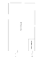
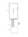
次に液晶表示装置Aの液晶パネル1について図面を参照して説明する。図2は本発明にかかる表示装置の液晶パネルと従来の液晶パネルの画素数を比較した図である。図2において、本発明にかかる液晶パネル1と従来の液晶パネルPrとの比較を明確にするため、1画素の大きさが同じとして比較している。すなわち、図2では液晶パネル1の面積が液晶パネルPrよりも大きく表示しているが、これは、画素数を掛止的に表しているものであり、実際のパネルの大きさを比較しているものとは限らない。なお、従来の液晶パネルPrは、いわゆる、フルHDと呼ばれるタイプであり、画素数が1920×1080ドットである。
液晶表示装置Aは、従来のフルHDよりもさらに高解像度な(以下、超高解像度と称する)画像表示が可能な表示装置であり、従来の液晶パネルPrよりも高解像度の液晶パネル1を用いている。図2に示しているように、液晶パネル1は、7680×4320ドット(8K4K)である。つまり、液晶パネル1は、フルHDの液晶パネルPrに対して、縦横ともに4倍の画素数を有しており、パネル全体では16倍の画素数を有している。なお、以下の説明において、本発明にかかる液晶表示装置A及び液晶パネル1を、フルHD液晶パネルPrに対し、8K4K液晶表示装置A及び8K4K液晶パネル1と称する場合がある。
すなわち、色数、フレームレートが同じ場合、8K4K液晶パネル1に対応した画像信号は、フルHD液晶パネルPrに対応した画像信号に対して、情報量がおよそ16倍になる。現在の通信インターフェースの規格では、このような超高解像度の画像信号を伝送するだけの伝送帯域を有していない。そのため、8K4K液晶表示装置Aでは、従来のフルHDの液晶パネルPrに対応した画像信号の送受信を行うための入力インターフェース31を16個並列に配置した、画像信号受信部3を用いている。そして、8K4K液晶表示装置Aに対応した画像信号を送信するため、16個の入力インターフェース31を並列に利用し、伝送信号の帯域を確保している。
このとき、16個の入力インターフェース31の全てが正確に同期している必要があり、インターフェースコントローラ32がすべての入力インターフェース31に入力される画像信号の同期を図っている。なお、1個の入力インターフェース31は、フルHDの液晶パネルPrを用いて、動画コンテンツを表示するときの情報量に対応できる伝送帯域を有している。
従来のフルHD液晶パネルPrを搭載した液晶表示装置は、テレビ等の動画コンテンツを表示することを主目的としている。そして、8K4K液晶表示装置Aのように超高解像度な表示装置でも、動画コンテンツを表示することに主眼を置いて設計されている。一方で、8K4K液晶表示装置Aは、高解像度であり細部まで詳細に表示することが可能であることから、電子看板、医療用ディスプレイ及び美術鑑賞用等、静止画コンテンツの表示に利用可能である。
上述しているとおり、動画コンテンツの場合、ちらつきを抑えるため高フレームレートでの駆動が必要である。一方で、静止画コンテンツの場合、動画コンテンツに比べて映像の書き換えの回数を減らしても、ちらつきやぼけが発生しない(発生しにくい)。そのため、静止画コンテンツの表示では、フレームレートを低くすることが可能となっている。フレームレートの低い画像信号は、高フレームレートの画像信号に比べてデータ量が少ない。
例えば、静止画コンテンツを表示する場合、動画コンテンツの表示ほど高いフレームレートが必要ではない。そこで、画像信号のフレームレートを、例えば、動画コンテンツの1/16にすることができる。これにより、静止画コンテンツの画像信号のデータ量は動画コンテンツの画像信号のデータ量の1/16となる。そこで、液晶表示装置Aにおいて、画像信号受信部3は、入力インターフェース31の伝送帯域を有効に利用するため、16個の入力インターフェース31のうち一部(例えば、1個)を介して信号源が接続されている場合でも、信号源からの画像信号を受信できるようになっている。
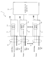
以下に入力インターフェース31の概略構成について図面を参照して説明する。図3は画像信号受信部を示す概略図である。図3は、入力インターフェース31の接続状態を示しており、実際の接続には、コネクタを介して接続しているが、コネクタの図示は省略している。また、図3において点線よりも右側が液晶表示装置Aであり、その液晶表示装置Aにインターフェースケーブル33が接続されている。つまり、液晶表示装置Aでは、インターフェースケーブル33を介して外部機器(信号源)と接続され、インターフェースケーブル33を経由して、画像信号が入力される。
液晶表示装置Aでは、入力インターフェース31ごとに接続状態を検出するためのEDIDメモリ311が取り付けられている。このEDIDメモリ311は、インターフェースケーブル33より電力が供給される構成となっており、電力が供給されると、液晶表示装置Aに接続された信号源の機器に、液晶表示装置Aの情報(例えば、液晶パネルのベンダー、機種、解像度、適合周波数等)を送信する。
例えば、液晶表示装置Aが1番から16番までの入力インターフェース31を備えており、1番から4番までにインターフェースケーブル33が接続されている場合、1番から4番までの入力インターフェース31のEDIDメモリ311が、インターフェースケーブル33を介して、接続されている機器に液晶表示装置Aの情報を送信する。
そして、インターフェースコントローラ32は、インターフェースケーブル33が接続されている入力インターフェース31を検出することができる(ホットプラグ)。そして、入力インターフェース31に接続されているインターフェースケーブル33の本数の情報は、インターフェースコントローラ32から、制御部7に送信される。制御部7は、接続されているインターフェースケーブル33の本数によって、液晶パネル1で表示するフレームレートを決定する。制御部7の詳細な動作については、後述する。
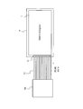
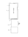
次に本発明にかかる表示装置に対する外部機器(画像信号源)の接続状態を図面を参照して説明する。図4は本発明にかかる表示装置に動画コンテンツの画像信号を伝送する信号源を接続した接続状態を示す概略図であり、図5は本発明にかかる表示装置に静止画コンテンツの画像信号を伝送する信号源を接続した接続状態を示す概略図である。なお、図4及び図5に示す信号源は8K4K液晶パネルに対応した超高解像度の画像信号を送信する信号源である。
8K4K液晶表示装置Aでは、解像度7680×4320ドットで、フレームレート60fpsの動画コンテンツの表示を定格動作としている。そして、液晶表示装置Aは、信号帯域を確保するため16個の入力インターフェース31を並列で使用することを前提として設計されている。
図4に示す信号源S1は、解像度7680×4320ドットで、フレームレート60fpsの動画コンテンツの画像信号を伝送するものである。このとき、画像信号のリフレッシュレートは60Hzとなっている。そのため、信号源S1と液晶表示装置Aとの接続は、16本のインターフェースケーブル33を利用している。
一方で、図5に示す信号源S2は、解像度7680×4320ドットの静止画コンテンツの画像信号を伝送するものである。上述しているとおり、静止画コンテンツを表示する場合、表示の切り替え前後で同じ映像であるため、動画コンテンツに比べてフレームレートが低く設定されている(例えば、4fps)。このとき、静止画コンテンツの画像信号のリフレッシュレートは4Hzである。
静止画コンテンツの画像信号は、動画コンテンツの画像信号よりもデータ量が少なくなる。信号源S2から送信される画像信号は、解像度が7680×4320ドット、リフレッシュレート4Hzであるため、1本のインターフェースケーブル33で伝送可能なデータ量である。そのため、信号源S2と液晶表示装置Aとの接続は、1本のインターフェースケーブル33を利用して行われている(図5参照)。
液晶表示装置Aにおいて、動画信号入力部3は、使用される入力インターフェース31の個数にかかわらず画像信号を受信することが可能となっている。そして、液晶表示装置Aでは、使用者の指示(手動)に基づいて或いは自動的に、入力される画像信号の種類を判別し、入力される画像信号に対応して液晶パネル1を駆動する。
以上示した信号源S1又はS2の切替えを手動で行う場合について説明したのち、液晶表示装置が自動的に切り替える動作について説明する。液晶表示装置Aの制御部7は、上述しているとおり、入力インターフェース31に接続されているインターフェースケーブル33の本数は取得している。
使用者は、液晶表示装置Aに接続した信号源が、図4に示す信号源S1のような動画コンテンツの画像信号を伝送するものか、或いは、図5に示す信号源S2のような静止画コンテンツの画像信号を伝送するものかの情報を液晶表示装置Aに入力する。すなわち、動画コンテンツを表示するのか、静止画コンテンツを表示するのかの情報を入力する。
なお、この入力は液晶表示装置Aに備えられているスイッチやリモートコントローラ等の入力装置を介して行われる。また、液晶表示装置Aでは、動画コンテンツの表示を基準に設計されているものであるため、動画コンテンツを表示する場合は入力を行わず、静止画コンテンツを表示するときに、上述の入力を行うようにしてもよい。以下の説明では、静止画コンテンツの表示の入力があった場合について説明する。
入力装置からの入力があると、制御部7はメモリ8より静止画コンテンツを表示するときのフレームレートを呼び出し、そのときの動作の条件を画像信号処理回路4に送信する。
また、制御部7は、入力インターフェース31に接続されているインターフェースケーブル33の本数の情報を取得しているため、動画コンテンツの画像信号を伝送する信号源S1が接続されているときに、静止画コンテンツ表示用の入力がなされても、誤入力であると判断し、フレームレートの切り替えを行わない。なお、静止画コンテンツ表示用の入力は、単純に切り替えのための入力であってもよいし、フレームレートを指定するような入力であってもよい。
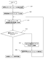
以下に、本発明にかかる表示装置の動作について図面を参照して説明する。図6は本発明にかかる表示装置の動作を示すフローチャートである。以下の説明では、液晶表示装置Aが接続されている信号源を自動的に判別し、伝送される画像信号に合わせて適切な処理を行う工程を示している。
図6に示すように、制御部7は、インターフェースコントローラ32より、入力インターフェース31に接続されているインターフェースケーブル33の本数の情報を取得する(ステップS11)。制御部7は、接続されているインターフェースケーブル33の本数に基づいて、伝送される画像信号のリフレッシュレートを決定する(ステップS12)。そして、制御部7は決定したリフレッシュレートを画像信号処理回路4に送信する(ステップS13)。
例えば、制御部7は、入力インターフェース31に接続されているインターフェースケーブル33の本数が16本との情報を取得する(ステップS11)と、動画コンテンツの画像信号を送信する信号源S1が接続されていると判断する(ステップS12)。そして、制御部7は画像信号処理回路4に対し、伝送される画像信号のリフレッシュレートが60Hzである旨の情報を送信する(ステップS13)。
一方、制御部7は、入力インターフェース31に接続されているインターフェースケーブル33の本数が1本との情報を取得する(ステップS11)と、静止画コンテンツの画像信号を伝送する信号源S2が接続されていると判断する(ステップS12)。そして、制御部7は、画像信号処理回路4に伝送される画像信号のリフレッシュレートが4Hzであるとの情報を送信する(ステップS13)。
画像信号処理回路4は、制御部7より取得したリフレッシュレートに従って、画像信号受信部3より受信した画像信号をフレーム画像信号を生成し、液晶駆動回路5に送信する。液晶駆動回路5は、フレーム画像信号に基づいて、液晶パネル1を駆動する。
つまり本発明にかかる表示装置では、接続された信号源が出力する画像信号のリフレッシュレート(映像コンテンツのフレームレート)の変更を、入力インターフェース31に接続されるインターフェースケーブル33の本数(すなわち、画像信号の受信に利用される入力インターフェース31の数)を変更することで対応している。これにより、各入力インターフェース31(インターフェースケーブル33)は常に一定の伝送レートで画像信号が伝送されるため、制御が容易であるとともに動作が安定する。また、画像信号のデータ量が小さいときは、入力インターフェース31に接続されるインターフェースケーブル33の本数が少なくなるので、インターフェースケーブル33の接続及び入力される画像信号の処理が煩雑になりにくい。
なお、静止画コンテンツの画像信号の送信において、入力インターフェース31及びインターフェースケーブル33を1個としているが、これに限定されるものではなく、画像信号のデータ量によって2個或いはそれ以上となる場合もある。
(第2実施形態)
本発明にかかる表示装置の他の例である液晶表示装置について図面を参照して説明する。図7は本発明にかかる表示装置の他の例である液晶表示装置と信号源との接続を示す概略図である。なお、図7に示す液晶表示装置Aは、制御部7の制御が異なる以外、構成が同じであり、液晶表示装置Aの構成は、図1に示すものと同じである。
本発明にかかる表示装置の他の例である液晶表示装置について図面を参照して説明する。図7は本発明にかかる表示装置の他の例である液晶表示装置と信号源との接続を示す概略図である。なお、図7に示す液晶表示装置Aは、制御部7の制御が異なる以外、構成が同じであり、液晶表示装置Aの構成は、図1に示すものと同じである。
例えば、スポーツ等の動きが激しい動画コンテンツの場合、画像の動きによるぼけやちらつきが発生しやすいので、60fpsといった高いフレームレートが必要である。一方で、語学講座等のような動きが少ない動画コンテンツの場合、動きが激しい動画コンテンツの半分(30fps)のフレームレートでも、ちらつきやぼけが発生しにくい。すなわち、このような、低いフレームレートの動画コンテンツの画像信号のリフレッシュレートは、動きが激しい動画コンテンツの画像信号よりも低くてもよい(ここでは、半分)。
以下の説明において、フレームレート60fpsの動画コンテンツを高フレームレートとし、この画像信号を高リフレッシュレートの画像信号とする。また、フレームレート30fpsの動画コンテンツを低フレームレートとし、この画像信号を低リフレッシュレートの画像信号とする。
図7に示すように、液晶表示装置Aには、フレームレートが低い映像コンテンツの画像信号を送信する信号源S3も接続可能となっている。信号源S3より送信される画像信号は、フレームレート30fpsの映像コンテンツであるため、図4に示す信号源S1から送信される画像信号の約半分のリフレッシュレート(すなわち、リフレッシュレート30Hz)である。これにより、信号源S3と液晶表示装置Aとの間の接続は、信号源S1を接続するときの半分のインターフェースケーブル33、すなわち、8本のインターフェースケーブル33で行われる。換言すると、低リフレッシュレートの画像信号を受信する場合、8個の入力インターフェース31を利用して行われる。
このように、画像信号のデータ量に合わせて、使用される入力インターフェース31の個数を変更し、信号帯域を調整するため、各入力インターフェース31では、画像信号のリフレッシュレートにかかわらず、一定の伝送レートとなるため、制御が容易になる。
このとき、制御部7は、入力インターフェース31に接続されているインターフェースケーブル33の本数の情報(すなわち、使用されている入力インターフェース31の個数)を取得している。そして、メモリ8のデータベースを参照して、使用されている入力インターフェース31の個数によって、入力される画像信号のリフレッシュレートを判別している。
例えば、図4に示すように16個の入力インターフェース31が使用されている情報を取得すると、制御部7は、接続された信号源から伝送される画像信号は、高リフレッシュレートの画像信号であると判断する。また、8個の入力インターフェース31が使用されている(図7参照)情報を取得すると、制御部7は、接続された信号源から伝送される画像信号は、低リフレッシュレートの画像信号であると判断する。さらに、1個の入力インターフェース31が使用されている(図5参照)情報を取得すると、制御部7は接続された信号源から伝送される画像信号は、非常にリフレッシュレートが低い画像信号(ここでは、静止画コンテンツの画像信号)であると判断する。
そして、制御部7は、伝送された画像信号に対応したフレームレートをメモリ8のデータベースより呼び出すとともにフレームレートを決定し、画像信号処理回路4に決定したフレームレートを送信する。
本実施形態では、出力する画像信号のリフレッシュレートが60Hzの信号源S1、リフレッシュレートが4Hzの信号源S2、リフレッシュレートが30Hzの信号源S3の3個としているが、これに限定されるものではなく、これら以外の信号源が用いられる場合もある。その場合、制御部7は、入力インターフェース31が使用されている個数に応じ、接続されている信号源のリフレッシュレートを認識する。
そして、制御部7は、使用されている入力インターフェース31の個数に基づいて、メモリ8のデータベースからリフレッシュレートを抽出しているが、これに限定されるものではない。例えば、総入力インターフェース31の個数に対する使用されている入力インターフェース31の個数の比率で、接続されている信号源のリフレッシュレート(映像コンテンツのフレームレート)を判別するものであってもよい。
例えば、12個の入力インターフェース31が使用されている場合、使用されている入力インターフェース31の割合は、75%であるので、60Hzの75%、すなわち、45Hzのリフレッシュレートの画像信号が伝送される信号源が接続されていると判断してもよい。
その他の特徴は第1実施形態と同じである。
(第3実施形態)
本発明にかかる表示装置の他の例について図面を参照して説明する。図8は本発明にかかる表示装置の他の例である液晶表示装置と信号源との接続を示す概略図である。なお、図8に示す液晶表示装置Aは、制御部7の制御が異なる以外、構成が同じであり、液晶表示装置Aの構成は、図1に示すものと同じである。
本発明にかかる表示装置の他の例について図面を参照して説明する。図8は本発明にかかる表示装置の他の例である液晶表示装置と信号源との接続を示す概略図である。なお、図8に示す液晶表示装置Aは、制御部7の制御が異なる以外、構成が同じであり、液晶表示装置Aの構成は、図1に示すものと同じである。
第1実施形態及び第2実施形態に記載の表示装置(液晶表示装置A)では、表示する映像コンテンツが、8K4K液晶パネル1に対応したもの、つまり、動画、静止画にかかわらず解像度が7680×4320ドットで、フレームレート(画像信号のリフレッシュレート)が異なるものとしていた。一方で、例えば、観察者から離れた場所に配置された表示装置の場合、細部の詳細な表示が不要な場合或いは超高解像度の映像表示が不要である場合もある。
このような場合において、8K4Kの液晶表示装置Aで、解像度が8K4Kの約1/4の3840×2160ドット(以下、4K2Kと称する場合がある)の映像コンテンツを表示しても、観察者に画像の粗さを認識されることは少ない。このように、4K2Kの映像コンテンツの解像度は、8K4Kの映像コンテンツの1/4であるため、リフレッシュレート60Hzの場合でも、画像信号のデータ量は約1/4になる。
そのため、図8に示すように、4K2Kの映像コンテンツの画像信号を伝送する信号源S4は、4個の入力インターフェース31を使用して、液晶表示装置Aに接続されている。
次に、このような信号源S4を含む信号源が接続されたときの液晶表示装置Aの動作について図面を参照して説明する。図9は図8に示す液晶表示装置の動作を示すフローチャートである。
液晶表示装置Aにおいて、制御部7は使用されている入力インターフェース31の個数を取得している(ステップS21)。そして、制御部7は、使用されている入力インターフェース3の個数に基づいて、接続された信号源から伝送される画像信号のリフレッシュレートを決定する(ステップS22)。
ここで、制御部7の信号源のリフレッシュレートの決定について説明する。上述の通り液晶表示装置Aは、8K4Kの映像コンテンツを60fpsで駆動することを定格動作として設計されている。そのため、制御部7は接続された信号源より伝送される画像信号は、8K4Kの解像度を有する映像コンテンツの画像信号であるとして、リフレッシュレートを決定する。
制御部7は決定したリフレッシュレートを画像信号処理回路4に送信する(ステップS23)。上述しているように、8K4Kの液晶表示装置Aの定格動作時の映像コンテンツよりも解像度の低い、映像コンテンツの画像信号を伝送する信号源が接続される場合がある。すなわち、使用されている入力インターフェース31の個数と画像のリフレッシュレートとが必ずしも比例しない。
そのため、画像信号処理回路4は、制御部7より受け取ったリフレッシュレートが信号源より伝送された画像信号に対して最適な値であるか(画像信号のリフレッシュレートと同じ或いはほぼ同じであるか)判断する(ステップS24)。制御部7より受け取ったリフレッシュレートが信号源より伝送された画像信号に最適である場合(ステップS24でYESの場合)、制御部7は、画像信号処理回路4の動作を続行させ、映像コンテンツを液晶パネル1に表示させる。
一方で、制御部7から取得したリフレッシュレートが信号源より伝送された画像信号に対して最適な値でない場合(ステップS24でNOの場合)、制御部7は最適ではない旨の信号を受信する。そして、制御部7は、信号源から伝送される画像信号の解像度が8K4Kの映像コンテンツではないと判断する(ステップS25)。そして、制御部7はメモリ8のデータベースにアクセスし、使用されている入力インターフェース31の個数に対応した解像度及びリフレッシュレートを抽出し、決定する(ステップS26)。
その後、ステップS23に戻り、リフレッシュレートを画像信号処理回路4に送信するとともに、このリフレッシュレートが信号源より伝送された画像信号に対して最適な値であるか判断する(ステップS24)。
以上のようにして、制御部7は信号源より伝送される画像信号に最適なリフレッシュレートを決定し、そのリフレッシュレートに基づいて、液晶表示装置Aを制御する。
例えば、4K2Kの映像コンテンツの画像信号を伝送する信号源S4が液晶表示装置Aに表示されている場合について説明する。4個の入力インターフェース31が使用されているため、制御部7は定格動作時のリフレッシュレート(60Hz)の1/4、すなわち、リフレッシュレート15Hzと判断する。しかしながら、実際の映像信号のリフレッシュレートは60Hzであるため、画像信号に対して適していない。そこで、制御部7は、伝送される画像信号の解像度が定常動作時と異なると判断し、4個の入力インターフェース31が使用されている場合の解像度とリフレッシュレートとの組み合わせをメモリ8のデータベースより取得する。制御部7は、解像度を変更しつつ、リフレッシュレートを選択し、画像信号に最適なリフレッシュレートを決定する。
メモリ8のデータベースとして、使用されている入力インターフェース31の個数毎に、解像度とリフレッシュレートの組み合わせが設定されたデータベースを利用している。また、上述の実施形態では、解像度、リフレッシュレートによって、画像信号のデータ量が変動するものとして説明しているが、画像信号のデータ量はこれ以外にも、例えば、色数にも左右される。そこで、メモリ8に、解像度と色数とリフレッシュレートとの組み合わせたデータベースを備えておき、制御部7はこのデータベースによってリフレッシュレートを決定してもよい。なお、解像度、色数以外のパラメータによって、画像信号のリフレッシュレートが決定されるものであってもよい。
これ以外の効果については、第1実施形態及び第2実施形態と同じである。
(第4実施形態)
本発明にかかる表示装置のさらに他の例について図面を参照して説明する。図10は本発明にかかる表示装置のさらに他の例である液晶表示装置と信号源との接続を示す概略図である。なお、図10に示す液晶表示装置Aは、制御部7の制御が異なる以外、構成が同じであり、液晶表示装置Aの構成は、図1に示すものと同じである。
本発明にかかる表示装置のさらに他の例について図面を参照して説明する。図10は本発明にかかる表示装置のさらに他の例である液晶表示装置と信号源との接続を示す概略図である。なお、図10に示す液晶表示装置Aは、制御部7の制御が異なる以外、構成が同じであり、液晶表示装置Aの構成は、図1に示すものと同じである。
図1に示すように、液晶表示装置Aは、16個の入力インターフェース31を備えている。8K4Kの映像コンテンツの画像信号でリフレッシュレートが60Hzのものを伝送する信号源S1のときは、16個全ての入力インターフェース31を用いる。一方で、リフレッシュレート30Hzの画像信号を伝送する信号源S31(S3)の場合、画像信号のデータ量が約半分となるので、8個の入力インターフェース31を用いての接続が可能となっている。
このとき、画像信号受信部3には、8個の入力インターフェース31が空きとなっている。空きの入力インターフェース31に、リフレッシュレート30Hzの画像信号を伝送する信号源S32を接続している(図10参照)。
複数個(ここでは、2個)の30Hzの画像信号を伝送する信号源S31、S32を接続した液晶表示装置Aにおいて、信号源S31からの画像信号と信号源S32からの画像信号の表示方法としては、信号源S31からの画像信号と信号源S32からの画像信号とを交互或いは観察者の選択に合わせて表示することができる。
また、液晶パネル1の画面を上下もしくは左右に分割して表示するもの、一方の映像コンテンツを他方の映像コンテンツの内部に小ウィンドで表示するものを挙げることができる。
なお、図10に示す液晶表示装置Aでは、2個の信号源を接続しているが、2個以上の信号源を接続する構成であってもよい。また、複数個接続される信号源として、リフレッシュレートが60Hzよりも小さいものを例に説明しているが、これに限定されるものではなく、8K4Kよりも小さい解像度の画像信号を伝送する信号源を複数個や、色数が異なる画像信号を伝送する信号源を接続する構成であってもよい。
異なる、リフレッシュレート、解像度の信号源を接続する場合、各信号源から伝送される画像信号のリフレッシュレート、解像度等を正確に検出することが必要になる。このような、信号源毎のリフレッシュレート、解像度を検出することができる入力インターフェースを図面を参照して説明する。図11は本発明にかかる表示装置に用いられる画像信号受信部の他の例の概略図である。
図11に示すように、画像信号受信部3Bは、入力インターフェース31BにEDIDメモリ311の替わりに、EDIDインターフェース312を備えている。そして、EDIDインターフェース312は、インターフェースコントローラ32と接続されている。それ以外は、画像信号受信部3と同じ構成を有しており、実質上同じ部分は同じ符号を付している。
図11に示すように、EDIDインターフェース312は、信号源側に接続されているとともに、インターフェースコントローラ32側にも接続されている。EDIDインターフェース312は、双方向インターフェースであり、入力インターフェース31Bごとに1個ずつ備えられている。そして、入力インターフェース31Bにインターフェースケーブル33が接続されることで、信号源からEDIDインターフェース312にリフレッシュレート、解像度、機器の固有情報等の情報が入力される。この情報は、EDIDインターフェース312を介しインターフェースコントローラ32に送られ、制御部7に送信される。このとき、インターフェースコントローラ32は、接続されている入力インターフェース31の情報とともに、信号源の情報を制御部7送信する。
制御部7は、信号源が接続されている入力インターフェース31の情報及びその信号源より伝送される画像信号の解像度、リフレッシュレートを取得することができる。これにより、制御部7は、画像信号受信部3Bに接続された信号源が接続された入力インターフェース31の情報及び各信号源から伝送される画像信号の解像度及びリフレッシュレートをそれぞれ正確に把握することができる。
なお、EDIDインターフェース312は、EDIDメモリ311と同様、信号源に液晶表示装置Aの情報を送信することが可能である。また、EDIDインターフェース312は、液晶表示装置Aの電源がONのとき、液晶表示装置Aより電力が供給され、液晶表示装置Aの電源がOFFのとき、信号源から電力が供給されるような回路を有している。
このような構成の画像信号受信部3Bを用いることで、複数個の信号源を正確に認識することができ、各信号源より伝送される画像信号に基づいた映像コンテンツを素早く且つ正確に表示することが可能である。
上述の各実施形態において、入力インターフェースの規格として、HDMI(登録商標)を挙げているが、これに限定されるものではなく、DisplayPort(登録商標)等、既存の画像信号の転送規格を広く採用することができる。また、入力インターフェースの個数は16個に限定されるものではなく、表示する映像コンテンツの画像信号を送信することができる信号帯域を確保することができる本数を広く採用することができる。
また、上述の実施形態において、液晶パネル1として、解像度が7680×4320ピクセルのものを例に説明しているが、これに限定されるものではない。フルHDの液晶パネルPrよりも大きな解像度を有するものを広く採用することができる。例えば、3840×2160ピクセル(4K2K)の液晶パネルを用い、複数個の入力インターフェース31で信号源と接続するものであってもよい。
さらに、上述の実施形態において、液晶パネル1として、リフレッシュレート60Hzのものを用いて説明しているが、これに限定されるものではない。例えば、120Hz等さらに高いリフレッシュレートのものを用いてもよい。なお、リフレッシュレートが120Hzの場合、伝送されるデータ量も多くなるので、入力インターフェース31の個数も多くなる(例えば、単純に60Hzのときの倍の32個)。
以上、本発明の実施形態について説明したが、本発明はこの内容に限定されるものではない。また本発明の実施形態は、発明の趣旨を逸脱しない限り、種々の改変を加えることが可能である。
本発明は、信号源S1(S2、S3、S4)が接続され、信号源S1(S2、S3、S4)からの画像信号を受信する画像信号受信部3と、制御部7とを備え、画像信号に基づいた映像コンテンツを表示する表示装置Aであり、画像信号受信部3は、複数個の入力インターフェース31を備え、画像信号受信部3は、前記複数個の入力インターフェース31のうち、画像信号のデータ量に対応した信号帯域を得ることができる個数の入力インターフェース31を並列に用いて、信号源S1(S2、S3、S4)からの画像信号を受信していることを特徴としている。
これにより、信号源より出射される画像信号のデータ量によって、使用する入力インターフェース31を変更することができるので、信号源S1(S2、S3、S4)と表示装置Aとの不必要な配線の接続を省略することがかのうである。これにより、接続が煩雑になるのを抑制することができる。また、データ量の少ない画像信号の場合、少ない入力インターフェース31を利用して、画像信号を伝送するので、画像信号の信号処理が複雑になるのを抑制することができる。
本発明の表示装置は、画像信号受信部3が、信号源S1(S2、S3、S4)からの画像信号の受信に使用している入力インターフェース31の個数を検出する検出部32を備えており、制御部7は検出部(インターフェースコントローラ32)が検出した使用している入力インターフェース31の数を参照して、信号源S1(S2、S3、S4)から受信する画像信号の種別を判別することもできる。
これにより、制御部7が使用している入力インターフェースの個数で、画像信号の種別(例えば、動画コンテンツ又は静止画コンテンツ)を判別するので、短時間で、画像信号の種別を判別することができる。
本発明の表示装置は、入力インターフェース31Bは、少なくとも信号源S1(S2、S3、S4)の情報を取得する情報取得部(EDIDインターフェース312)を備えており、制御部7が、情報取得部(EDIDインターフェース312)の情報を参照して、画像信号の種別を判別することができる。
これにより、制御部7がEDIDインターフェース312より信号源S1(S2、S3、S4)の情報を検出するので、制御部7が、迅速かつ確実に画像信号の種別を判別できる。
本発明の表示装置は、使用されている入力インターフェース31の数と画像信号の種別の情報とを関連付けたデータベースを更に備えており、制御部7が、データベースに基づいて、画像信号の種別を判別することも可能である。
これにより、制御部7がデータベースに基づいて画像信号の種別を判別するので、画像信号の種別の判別が容易になる。
本発明の表示装置は、制御部7が、少なくとも、表示可能な動画コンテンツの画像信号と、静止画コンテンツの画像信号とを判別することも可能である。
これにより、画像信号の種類を決めておくことで、画像信号の種別の判別が容易となる。
本発明の表示装置では、制御部7が、信号源S1(S2、S3、S4)から受信する画像信号のリフレッシュレートを判別している。
これにより、制御部7がリフレッシュレートを判別するため、判別が容易となる。
本発明の表示装置では、制御部7が、信号源S1(S2、S3、S4)から受信する画像信号の解像度を判別する。
これにより、制御部7が解像度を判別するものであるため、判別が容易となる。
本発明の表示装置は、画像信号受信部3には、異なる複数個の信号源S1(S2、S3、S4)が並列に接続されている。
これにより、複数個の信号源S1(S2、S3、S4)が接続されていることから、超高解像度の画像信号を送信できる信号源S1(S2、S3、S4)がない場合でも、超高解像度な表示装置Aの有効利用が可能である。
本発明は、異なる解像度、リフレッシュレートの画像信号を入力することができる高解像度の液晶表示装置等の表示装置に適用可能である。
A 液晶表示装置
1 液晶パネル
2 バックライト
3 画像信号受信部
31 入力インターフェース
32 インターフェースコントローラ
33 インターフェースケーブル
4 画像信号処理回路
5 液晶駆動回路
6 バックライト駆動回路
7 制御部
8 メモリ
1 液晶パネル
2 バックライト
3 画像信号受信部
31 入力インターフェース
32 インターフェースコントローラ
33 インターフェースケーブル
4 画像信号処理回路
5 液晶駆動回路
6 バックライト駆動回路
7 制御部
8 メモリ
Claims (5)
- 信号源が接続され、前記信号源からの画像信号を受信する画像信号受信部と、
制御部とを備え、前記画像信号に基づいた映像コンテンツを表示する表示装置であって、
前記画像信号受信部は、複数個の入力インターフェースを備えており、
前記画像信号受信部が、前記複数個の入力インターフェースのうち、前記画像信号のデータ量に対応した信号帯域を得ることができる個数の前記入力インターフェースを用いて、前記信号源からの画像信号を受信していることを特徴とする表示装置。 - 前記画像信号受信部が、前記信号源からの画像信号の受信に使用している入力インターフェースの個数を検出する検出部を備えており、
前記制御部は前記検出部が検出した使用している前記入力インターフェースの数を参照して、前記信号源から受信する画像信号の種別を判別する請求項1に記載の表示装置。 - 前記入力インターフェースは、少なくとも前記信号源の情報を取得する情報取得部を備えており、
前記制御部が、前記情報取得部の情報を参照して、前記画像信号の種別を判別する請求項2に記載の表示装置。 - 前記制御部が、前記信号源から受信する前記画像信号のリフレッシュレートを判別する請求項2又は請求項3に記載の表示装置。
- 前記画像信号受信部には、異なる複数個の前記信号源が並列に接続されている請求項1から請求項4のいずれかに記載の表示装置。
Applications Claiming Priority (2)
| Application Number | Priority Date | Filing Date | Title |
|---|---|---|---|
| JP2012251124 | 2012-11-15 | ||
| JP2012-251124 | 2012-11-15 |
Publications (1)
| Publication Number | Publication Date |
|---|---|
| WO2014077157A1 true WO2014077157A1 (ja) | 2014-05-22 |
Family
ID=50731072
Family Applications (1)
| Application Number | Title | Priority Date | Filing Date |
|---|---|---|---|
| PCT/JP2013/079954 Ceased WO2014077157A1 (ja) | 2012-11-15 | 2013-11-06 | 表示装置 |
Country Status (1)
| Country | Link |
|---|---|
| WO (1) | WO2014077157A1 (ja) |
Cited By (2)
| Publication number | Priority date | Publication date | Assignee | Title |
|---|---|---|---|---|
| KR20170099456A (ko) * | 2016-02-23 | 2017-09-01 | 삼성디스플레이 주식회사 | 표시 장치, 표시 장치의 구동 방법 및 영상 표시 시스템 |
| CN112333384A (zh) * | 2020-10-27 | 2021-02-05 | 北京小米移动软件有限公司 | 预览图像方法、预览图像装置及存储介质 |
Citations (4)
| Publication number | Priority date | Publication date | Assignee | Title |
|---|---|---|---|---|
| JP2002300545A (ja) * | 2001-04-03 | 2002-10-11 | Matsushita Electric Ind Co Ltd | データ処理システム |
| JP2011180336A (ja) * | 2010-03-01 | 2011-09-15 | Seiko Epson Corp | 画像処理装置、投写型表示装置、映像表示システム、画像処理方法、コンピュータープログラム |
| WO2012067073A1 (ja) * | 2010-11-19 | 2012-05-24 | シャープ株式会社 | データ転送回路、データ転送方法、表示装置、ホスト側装置、および電子機器 |
| WO2013024753A1 (ja) * | 2011-08-12 | 2013-02-21 | シャープ株式会社 | 表示システム、ホスト装置、および表示装置 |
-
2013
- 2013-11-06 WO PCT/JP2013/079954 patent/WO2014077157A1/ja not_active Ceased
Patent Citations (4)
| Publication number | Priority date | Publication date | Assignee | Title |
|---|---|---|---|---|
| JP2002300545A (ja) * | 2001-04-03 | 2002-10-11 | Matsushita Electric Ind Co Ltd | データ処理システム |
| JP2011180336A (ja) * | 2010-03-01 | 2011-09-15 | Seiko Epson Corp | 画像処理装置、投写型表示装置、映像表示システム、画像処理方法、コンピュータープログラム |
| WO2012067073A1 (ja) * | 2010-11-19 | 2012-05-24 | シャープ株式会社 | データ転送回路、データ転送方法、表示装置、ホスト側装置、および電子機器 |
| WO2013024753A1 (ja) * | 2011-08-12 | 2013-02-21 | シャープ株式会社 | 表示システム、ホスト装置、および表示装置 |
Cited By (3)
| Publication number | Priority date | Publication date | Assignee | Title |
|---|---|---|---|---|
| KR20170099456A (ko) * | 2016-02-23 | 2017-09-01 | 삼성디스플레이 주식회사 | 표시 장치, 표시 장치의 구동 방법 및 영상 표시 시스템 |
| KR102460221B1 (ko) | 2016-02-23 | 2022-10-31 | 삼성디스플레이 주식회사 | 표시 장치, 표시 장치의 구동 방법 및 영상 표시 시스템 |
| CN112333384A (zh) * | 2020-10-27 | 2021-02-05 | 北京小米移动软件有限公司 | 预览图像方法、预览图像装置及存储介质 |
Similar Documents
| Publication | Publication Date | Title |
|---|---|---|
| CN110114818B (zh) | 显示驱动方法、驱动装置及显示装置 | |
| US11132959B2 (en) | Electronic device and control method thereof | |
| CN102737599B (zh) | 显示单元和显示方法 | |
| US9972264B2 (en) | Display device and driving method thereof | |
| TWI419135B (zh) | 以調整背光亮度產生立體影像效果的液晶顯示系統及方法 | |
| CN102118592B (zh) | 用于显示多视频的系统 | |
| KR102325816B1 (ko) | 저속 구동이 가능한 표시장치와 그 구동방법 | |
| US20090244112A1 (en) | Display apparatus and method thereof | |
| US8368624B2 (en) | Display method with interlacing reversal scan and device thereof | |
| JP6282601B2 (ja) | 表示装置 | |
| US10930248B2 (en) | Display method and display system for reducing a double image effect | |
| US20090102864A1 (en) | Driving method for color sequential display | |
| US20120007969A1 (en) | Method for reducing left-eye/right-eye crosstalk in a 3d liquid crystal display device and related display system | |
| KR20180065194A (ko) | 유기 발광 표시 장치 및 그의 구동 방법 | |
| US20230230527A1 (en) | Display apparatus and driving method thereof | |
| US20130106895A1 (en) | Display device and driving method thereof | |
| CN108109591A (zh) | 显示屏的控制装置及笔记本面板 | |
| JP2009134237A (ja) | 表示装置 | |
| CN103956149B (zh) | 显示器、显示系统和数据处理方法 | |
| US10102817B2 (en) | Display device and driving method thereof | |
| CN102162927A (zh) | 以调整背光亮度产生立体影像效果的液晶显示系统及方法 | |
| KR102135923B1 (ko) | 입력 비디오 정보를 이용한 충전 시간 제어 장치 및 제어 방법 | |
| KR20140025740A (ko) | 표시 장치 및 그 구동 방법 | |
| WO2014077157A1 (ja) | 表示装置 | |
| US9105218B2 (en) | Display device capable of controlling external light and method for controlling external light |
Legal Events
| Date | Code | Title | Description |
|---|---|---|---|
| 121 | Ep: the epo has been informed by wipo that ep was designated in this application |
Ref document number: 13855052 Country of ref document: EP Kind code of ref document: A1 |
|
| NENP | Non-entry into the national phase |
Ref country code: DE |
|
| 122 | Ep: pct application non-entry in european phase |
Ref document number: 13855052 Country of ref document: EP Kind code of ref document: A1 |
|
| NENP | Non-entry into the national phase |
Ref country code: JP |