WO2014077086A1 - Shape sensing system - Google Patents
Shape sensing system Download PDFInfo
- Publication number
- WO2014077086A1 WO2014077086A1 PCT/JP2013/078414 JP2013078414W WO2014077086A1 WO 2014077086 A1 WO2014077086 A1 WO 2014077086A1 JP 2013078414 W JP2013078414 W JP 2013078414W WO 2014077086 A1 WO2014077086 A1 WO 2014077086A1
- Authority
- WO
- WIPO (PCT)
- Prior art keywords
- measurement
- shape
- unit
- orientation
- shape measuring
- Prior art date
Links
Images


Classifications
-
- G—PHYSICS
- G01—MEASURING; TESTING
- G01B—MEASURING LENGTH, THICKNESS OR SIMILAR LINEAR DIMENSIONS; MEASURING ANGLES; MEASURING AREAS; MEASURING IRREGULARITIES OF SURFACES OR CONTOURS
- G01B11/00—Measuring arrangements characterised by the use of optical techniques
- G01B11/24—Measuring arrangements characterised by the use of optical techniques for measuring contours or curvatures
-
- G—PHYSICS
- G01—MEASURING; TESTING
- G01B—MEASURING LENGTH, THICKNESS OR SIMILAR LINEAR DIMENSIONS; MEASURING ANGLES; MEASURING AREAS; MEASURING IRREGULARITIES OF SURFACES OR CONTOURS
- G01B11/00—Measuring arrangements characterised by the use of optical techniques
- G01B11/02—Measuring arrangements characterised by the use of optical techniques for measuring length, width or thickness
- G01B11/026—Measuring arrangements characterised by the use of optical techniques for measuring length, width or thickness by measuring distance between sensor and object
-
- G—PHYSICS
- G01—MEASURING; TESTING
- G01C—MEASURING DISTANCES, LEVELS OR BEARINGS; SURVEYING; NAVIGATION; GYROSCOPIC INSTRUMENTS; PHOTOGRAMMETRY OR VIDEOGRAMMETRY
- G01C15/00—Surveying instruments or accessories not provided for in groups G01C1/00 - G01C13/00
- G01C15/002—Active optical surveying means
- G01C15/008—Active optical surveying means combined with inclination sensor
-
- G—PHYSICS
- G01—MEASURING; TESTING
- G01S—RADIO DIRECTION-FINDING; RADIO NAVIGATION; DETERMINING DISTANCE OR VELOCITY BY USE OF RADIO WAVES; LOCATING OR PRESENCE-DETECTING BY USE OF THE REFLECTION OR RERADIATION OF RADIO WAVES; ANALOGOUS ARRANGEMENTS USING OTHER WAVES
- G01S17/00—Systems using the reflection or reradiation of electromagnetic waves other than radio waves, e.g. lidar systems
- G01S17/02—Systems using the reflection of electromagnetic waves other than radio waves
- G01S17/06—Systems determining position data of a target
- G01S17/42—Simultaneous measurement of distance and other co-ordinates
-
- G—PHYSICS
- G01—MEASURING; TESTING
- G01S—RADIO DIRECTION-FINDING; RADIO NAVIGATION; DETERMINING DISTANCE OR VELOCITY BY USE OF RADIO WAVES; LOCATING OR PRESENCE-DETECTING BY USE OF THE REFLECTION OR RERADIATION OF RADIO WAVES; ANALOGOUS ARRANGEMENTS USING OTHER WAVES
- G01S17/00—Systems using the reflection or reradiation of electromagnetic waves other than radio waves, e.g. lidar systems
- G01S17/86—Combinations of lidar systems with systems other than lidar, radar or sonar, e.g. with direction finders
-
- G—PHYSICS
- G01—MEASURING; TESTING
- G01S—RADIO DIRECTION-FINDING; RADIO NAVIGATION; DETERMINING DISTANCE OR VELOCITY BY USE OF RADIO WAVES; LOCATING OR PRESENCE-DETECTING BY USE OF THE REFLECTION OR RERADIATION OF RADIO WAVES; ANALOGOUS ARRANGEMENTS USING OTHER WAVES
- G01S3/00—Direction-finders for determining the direction from which infrasonic, sonic, ultrasonic, or electromagnetic waves, or particle emission, not having a directional significance, are being received
- G01S3/78—Direction-finders for determining the direction from which infrasonic, sonic, ultrasonic, or electromagnetic waves, or particle emission, not having a directional significance, are being received using electromagnetic waves other than radio waves
- G01S3/782—Systems for determining direction or deviation from predetermined direction
- G01S3/783—Systems for determining direction or deviation from predetermined direction using amplitude comparison of signals derived from static detectors or detector systems
- G01S3/784—Systems for determining direction or deviation from predetermined direction using amplitude comparison of signals derived from static detectors or detector systems using a mosaic of detectors
-
- G—PHYSICS
- G01—MEASURING; TESTING
- G01S—RADIO DIRECTION-FINDING; RADIO NAVIGATION; DETERMINING DISTANCE OR VELOCITY BY USE OF RADIO WAVES; LOCATING OR PRESENCE-DETECTING BY USE OF THE REFLECTION OR RERADIATION OF RADIO WAVES; ANALOGOUS ARRANGEMENTS USING OTHER WAVES
- G01S7/00—Details of systems according to groups G01S13/00, G01S15/00, G01S17/00
- G01S7/48—Details of systems according to groups G01S13/00, G01S15/00, G01S17/00 of systems according to group G01S17/00
- G01S7/481—Constructional features, e.g. arrangements of optical elements
- G01S7/4817—Constructional features, e.g. arrangements of optical elements relating to scanning
-
- G—PHYSICS
- G01—MEASURING; TESTING
- G01S—RADIO DIRECTION-FINDING; RADIO NAVIGATION; DETERMINING DISTANCE OR VELOCITY BY USE OF RADIO WAVES; LOCATING OR PRESENCE-DETECTING BY USE OF THE REFLECTION OR RERADIATION OF RADIO WAVES; ANALOGOUS ARRANGEMENTS USING OTHER WAVES
- G01S7/00—Details of systems according to groups G01S13/00, G01S15/00, G01S17/00
- G01S7/48—Details of systems according to groups G01S13/00, G01S15/00, G01S17/00 of systems according to group G01S17/00
- G01S7/497—Means for monitoring or calibrating
-
- G—PHYSICS
- G01—MEASURING; TESTING
- G01S—RADIO DIRECTION-FINDING; RADIO NAVIGATION; DETERMINING DISTANCE OR VELOCITY BY USE OF RADIO WAVES; LOCATING OR PRESENCE-DETECTING BY USE OF THE REFLECTION OR RERADIATION OF RADIO WAVES; ANALOGOUS ARRANGEMENTS USING OTHER WAVES
- G01S5/00—Position-fixing by co-ordinating two or more direction or position line determinations; Position-fixing by co-ordinating two or more distance determinations
- G01S5/16—Position-fixing by co-ordinating two or more direction or position line determinations; Position-fixing by co-ordinating two or more distance determinations using electromagnetic waves other than radio waves
- G01S5/163—Determination of attitude
Definitions
- the present invention relates to a shape measurement system
- Patent Document 1 JP-A-2005-180925.
- This publication states that “in a laser measurement system for measuring the three-dimensional shape of a measurement object using laser light, a measurement means for measuring the three-dimensional shape of the measurement object, and measurement at a plurality of positions by the measurement means”
- a storage means for storing measurement data relating to the three-dimensional shape of the measured object, and a three-dimensional shape calculation for calculating the three-dimensional shape of the measured object by combining the measurement data at a plurality of positions stored in the storage means
- the three-dimensional shape calculation means calculates the three-dimensional shape of the object to be measured by combining the measurement data at a plurality of positions stored in the storage means. It is described.
- Patent Document 2 Japanese Patent No. 4486737
- a camera combining a fish-eye lens and a line sensor horizontally with a predetermined imaging angle, two multi-line cameras, a DGPS receiver, and a laser in a different direction.
- a mobile mapping spatial information generating device for generating an image, the camera data having the GPS time, the means for linking the INS data having the GPS time to the camera data and laser data, and the laser data of each laser scanner Read the distance value to the measurement point indicated by each laser data, the angle of the laser direction with respect to the measurement point, Means for defining each three-dimensional geographic coordinate on the basis of NS data; means for synthesizing a unidirectional model of each laser defined by the respective three-dimensional geographic coordinate on the three-dimensional coordinate; Based on the INS data of the camera data, the model is divided into planes according to a predetermined condition, the divided area is converted into polygons, and the image data associated with each distance value and angle of the polygon is searched. And a means for allocating the processed image data to the polygon to generate the three-dimensional graphic image
- Patent Document 3 JP 2012-27883 A (Patent Document 3).
- an inner surface shape measuring apparatus for three-dimensionally measuring the inner surface shape of a tubular body, by scanning a laser beam in a vertical direction along the inner surface of the tubular body, First ranging data detection means for outputting ranging data for each direction of the irradiated laser beam; and scanning the laser beam in a direction inclined by a predetermined angle with respect to the vertical direction along the inner surface of the tube.
- a second ranging data detecting means for outputting ranging data for each azimuth of the laser beam irradiated on the inner surface of the tube, the first ranging data detecting means, and the second ranging Moving means for moving the data detection means in the axial direction of the tube, and respective positions when the first distance measurement data detection means and the second distance measurement data detection means are moved by the movement means
- Position coordinate detecting means for detecting coordinates, and the first A tilt angle between the moving means and the axis of the tube is calculated based on the distance measurement data detected by the distance measurement data detection means and the second distance measurement data detection means, and detected by the position coordinate detection means.
- a control means for generating the three-dimensional shape of the inner surface of the tubular body by correcting the position coordinates obtained based on the calculated inclination angle.
- Patent Document 2 the position and posture of a vehicle equipped with a plurality of cameras and a laser scanner are measured using a inertial navigation device and GPS, and the image data and the distance data of the laser scanner are combined into geographical coordinates.
- the position and orientation are measured using an inertial navigation system and GPS, the measurement accuracy is at most cm, and in addition to ensuring product quality in manufacturing, it is possible to achieve accuracy that can be used during processing and assembly. There is a problem that can not be.
- Patent Document 3 the inclination angle between the moving means and the measurement target axis is estimated based on the distance measurement data detected by the two distance measurement data detection means, and the shape measurement result is corrected. Since the sensor is not installed and the tilt angle between the moving means and the measurement target axis is estimated based on the distance measurement data detected by the distance measurement data detection means, the measurement accuracy depends on the movement accuracy. There is a problem such as.
- the present invention moves the shape measuring unit with moving means that does not need to be highly accurate, and measures the position and orientation of the shape measuring unit with high accuracy, thereby reducing the man-hours for installation and measurement.
- An object of the present invention is to provide a measurement shape measurement system that can measure a large shape of a measurement object with high accuracy, with a small number of methods, regardless of the accuracy of the moving means.
- the present application includes a plurality of means for solving the above-described problems.
- a distance sensor that measures the distance to the measurement object while rotating the measurement light, and a means for changing the measurement position of the distance sensor.
- a shape measuring system comprising: a shape measuring unit comprising: a moving unit that moves the shape measuring unit; and a position measuring unit that measures the position of the shape measuring unit.
- the three-dimensional shape of a large object can be measured by a fast and simple method.
- FIG. 3 is a cross-sectional view taken along a plane A in FIG. 2.
- FIG. 2 is an example diagram of a configuration in which the positions of a position / orientation measurement sensor unit 300 and a position / orientation measurement laser emitting unit 400 are interchanged in the configuration example of FIG.
- FIG. 2 is an example diagram of a configuration in which the positions of a position / orientation measurement sensor unit 300 and a position / orientation measurement laser emitting unit 400 are interchanged in the configuration example of FIG.
- FIG. 5 is a cross-sectional view perpendicular to the mounting wire 210.
- the block diagram which can extend the range which can measure a position and attitude
- the block diagram which can arrange
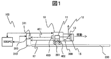
- FIG. 1 is an example of a configuration diagram of a shape measuring system 100 of the present embodiment.
- the shape measurement system 100 measures the delay time of the reflected light while rotating the laser beam from the shape measuring unit to the measurement object, and measures the cross-sectional shape of the measurement object. Further, the distance from the measurement start position of the shape measuring unit is calculated based on the arrival time of the laser light to the reflection sensor or the measurement sensor or the detection time of the reflected light with another laser light.
- Shape measurement comprising a distance sensor 11 for measuring a distance to a measurement object by laser light, a laser emitted light 12, a prism or reflecting plate 13 for changing an optical path of the laser emitted light 12, and a rotary stage 15 for rotating the prism 13.
- the shape measuring unit 10 is held on the simple rail 200, and the shape measuring unit 10 moves on the simple rail by the wheels 201. At this time, the position from the starting point is calculated by the position / orientation measurement laser emitting unit 400, the position measurement distance sensor 402, the inclination sensor 309, the position / orientation measurement sensor unit 300, and the PC 500 that performs control / data processing.
- the position / orientation measurement laser emitting unit 400, the position measurement distance sensor 402, the inclination sensor 309, and the position / orientation measurement sensor unit 300 are set to a reference point o (described in FIG. 3) of the position / orientation measurement sensor unit 300 as an origin.
- the position and orientation of the shape measuring unit 10 are measured and calculated. That is, the axes of the spatial coordinates x0, y0, z0 and x, y, z of the origin of the shape measuring unit 10 in the coordinate system with the reference point o (described in FIG. 3) of the position / orientation measurement sensor unit 300 as the origin are rotated. It plays the role of measuring the rotations ⁇ x, ⁇ y, ⁇ z around the axes.
- a beam splitter 310 serves to separate the posture measurement laser output 401 into two.
- the distance measuring method of the distance sensor 11 and the distance sensor 402 is not limited.
- the distance sensor 11 and the position measuring distance sensor 402 may be shared, and the output may be switched or the outputs may be divided.
- FIG. 2 is a view showing a state of being mounted on a railway vehicle 1 which is an example of a measurement target of the present embodiment, and FIG. An example in which the shape measuring system 100 measures the shape of the inner surface of the railway vehicle 1 will be described with reference to a cross-sectional view (FIG. 3) taken along the plane A in FIG.
- the PC 500 determines the irradiation position in the coordinate system of the shape measuring unit 10 based on the distance from the irradiation position of the output light 12 of the distance sensor 11 to the measurement target 1 as the measurement result of the distance sensor 11 and the rotation angle of the rotary stage 15.
- the spatial coordinates (x ′, y ′, z ′) are calculated.
- FIG. 4 is an example of a configuration diagram of the position and orientation measurement sensor unit 300.
- the beam splitter 310 serves to separate the attitude measurement laser output 401 into two.
- One of the separated light is received by a position detection element such as PSD (Position Sensitive Detector) 301, and the other is condensed on a position detection element such as PSD 302 by a lens 304.
- PSD 301 and PSD 302 play a role of calculating the coordinates of the center of the received laser. From the outputs dx and dy of the PSD 302, the rotations ⁇ x and ⁇ y with the x and y axes as the rotation axes are calculated from the following (Equation 1).
- the position and orientation of the shape measuring unit 10 with the reference point O of the position and orientation measuring sensor unit 300 as the origin that is, the shape
- the rotations ⁇ x, ⁇ y, and ⁇ z with the respective axes of the spatial coordinates x0, y0, z0 and x, y, z as the rotation axes are calculated.
- f represents the focal length of the lens 304.
- An imaging sensor such as a CCD may be used as the position detection element.
- FIG. 5A is an example of another configuration diagram of the position / orientation measurement sensor unit 300.
- the PSD 301 and the PSD 303 are arranged at positions where the distance from the beam splitter 310 is different by ⁇ L.
- the beam splitter 310 serves to separate the attitude measurement laser output 401 into two.
- One of the separated light is received by PSD 301 and the other is received by PSD 303.
- PSD 301 and PSD 303 are virtually arranged in series as shown in FIG. As shown in FIG.
- the position and orientation of the shape measuring unit 10 that is, the spatial coordinates x0 and y0 of the origin of the shape measuring unit 10 can be obtained.
- the PC 500 determines the irradiation position in the coordinate system of the shape measuring unit 10 from the spatial coordinates x0, y0, z0 and the rotations ⁇ x, ⁇ y, ⁇ z of the shape measuring unit 10 with the reference point o of the position / orientation measuring sensor unit 300 as the origin.
- a transformation matrix T for converting the spatial coordinates (x ′, y ′, z ′) into a coordinate system with the reference point o of the position / orientation measurement sensor unit 300 as the origin is obtained by (Equation 3).
- the PC 500 uses the transformation matrix T of (Equation 3) to perform coordinate transformation according to (Equation 4) below, and in the coordinate system with the reference point o of the position and orientation measurement sensor unit 300 as the origin, the emitted light 12 of the distance sensor 11 The spatial coordinates (x, y, z) of the irradiation position are obtained.
- FIG. 6 shows a configuration example in which the positions of the position / orientation measurement sensor unit 300 and the position / orientation measurement laser emitting unit 400 in the configuration example of FIG. 1 are interchanged.
- the positions of the position / orientation measurement sensor unit 300 and the position / orientation measurement laser emitting unit 400 are interchanged, a change in the incident position of the posture measurement laser output 401 on the position / orientation measurement sensor unit 300 due to a change in posture of the shape measurement unit 10 occurs. Since it becomes smaller, the range in which the posture change can be measured is expanded.
- the outgoing light 12 is manipulated on the cross section perpendicular to the longitudinal axis of the measuring object 1 using the prism 13 and the rotary stage 15, and the shape measuring unit 10 is moved on the simple rail 200 by the wheel 201 to move the distance sensor 11.
- the inner surface shape of the measuring object 1 is measured by operating the irradiation position of the outgoing light 12 and obtaining the spatial coordinates of the irradiation position of the outgoing light 12 of the measuring object 1.
- FIG. 1 An example of a shape measurement flowchart of the shape measurement system 100 is shown in FIG.
- the z-axis movement range and z-axis movement step number N are input (S101), moved to the initial position (S102), and measurement is started (S103).
- the shape measuring unit 10 records data (S104).
- the position and orientation of the shape measuring unit are measured (S105), a transformation matrix T is calculated (S106), and coordinate transformation is performed using the transformation matrix T (S107).
- It is determined whether or not the current step number i is equal to the set step number N (S108). If not, the movement is made in the z-axis direction (S109), the measurement is started again (S103), and the current step number is returned.
- the measurement is repeated until i becomes equal to the set step number N, and when the current step number i becomes equal to the set step number N, shape measurement data is output (S110).
- the output shape measurement data is compared with CAD data by the point cloud data processing software built in the PC500, and data processing such as extraction of dimension data from the shape measurement data is performed to correct the shape of the railway vehicle and at the time of shipment. Can be used as inspection data.
- a large object to be measured can be measured with high accuracy regardless of the accuracy of the moving means, for example, by a method with less man-hours for installation and measurement.
- a shape measurement system that can measure the shape of a measurement object exceeding 10 m with an accuracy of, for example, 1 mm or less.
- This embodiment is a modification of the first embodiment. Only differences from the first embodiment will be described.
- FIG. 8 is an example of a configuration diagram of the shape measurement system 600 according to the second embodiment.
- the adapter 230 serves to connect the shape measuring unit 10 and the mounting unit 214.
- the mounting unit 214 plays a role of mounting the shape measuring unit 10 on the mounting wire 210 fixed to the column 213.
- the motor 221 is disposed in the winding unit 220 and plays a role of moving the shape measuring unit using the moving wire 211.
- FIG. 9 shows details of the configuration of the adapter 230 and the mounting unit 214.
- the adapter 230 rotates around the z axis and keeps the shape measuring unit horizontal against gravity
- the movable mechanism 232 includes the x axis.
- a stopper 233 that limits the direction of movement so as not to rotate around
- a movable mechanism 231 that rotates around the x axis and keeps the shape measuring unit horizontal against gravity, and movable so that the movable mechanism 231 does not rotate around the z axis.
- a stopper 234 for limiting the direction, which makes it possible to reduce the rotations ⁇ x and ⁇ z around the x and z axes.
- the mounting portion 214 has wheels 216 and plays a role of traveling on the mounting wire 210.
- the mounting wire 210 bends in the direction of gravity, in this case the y-axis direction, due to the weight of the shape measuring unit 10, the adapter 230, and the mounting unit 214, and the weight of the mounting wire 210.
- the amount of deflection is most when the weight of the shape measuring unit 10, the adapter 230, and the mounting unit 214 is 3 kg, the mounting wire 210 is stainless steel with a diameter of 2 mm, the length is 25 m, and the mounting wire 210 is stretched with a tension of 200 kg. It will bend about 100 mm at the center position where it bends.
- the measurable range of the position / orientation measurement sensor unit 300 is determined by the size of the PSD 301, and the size is generally about 20 mm square, so the position can be reduced even when the deflection is reduced or there is a deflection. It is necessary to expand the measurement range of the position and orientation in the deflection direction so that the orientation can be measured.
- FIG. 11 shows a cross-sectional view perpendicular to the mounting wire 210.
- the mounting portion 214 has, for example, a U shape so as not to interfere with the relay support 223.
- the deflection is halved. If a plurality of, for example, ten relay posts 223 are used, it is possible to suppress the deflection below the size of the PSD 301 and to measure the position and orientation.
- the mounting thin metal roll 212 that is thick in the y-axis direction and thin in the x-axis direction, the deflection in the y-axis direction can be reduced, and the position and orientation can be reduced. Can be measured. Since the thin mounting thin metal roll 212 can be wound up, the mounting portion 214 can be mounted without impairing the portability.
- the posture measuring unit 300 is mounted on a y-axis stage 320 that plays a role of moving a load in the y-axis direction, and the shape measuring unit 10 is bent by the deflection of the mounting wire 210. It can be configured to move so as to follow a change in position in the y-axis direction.
- a plurality of lasers 400 a, 400 b, and 400 c are arranged in the y-axis direction in the position / orientation measuring laser emitting unit 400, and any one of the lasers is always applied to the sensor of the orientation measuring unit 300. Make it irradiating.
- the laser 400 a is arranged in advance so as to hit the sensor of the attitude measurement unit 300 and enters the image sensor 305. Since the mounting wire 210 can recognize which laser is irradiating the image sensor 305 even when the deflection shape measuring unit 10 moves in the y-axis direction, the range in which the position and orientation can be measured is in the y-axis direction. Can be spread. In this method, since the deflection can be followed without increasing the movable part, durability is improved and handling becomes easy.
- the winding wire 211 is wound up by the motor 221 and the shape measuring unit 10 is moved to measure the shape of the measuring object 1.
- the shape measuring unit 10 since the shape measuring unit 10 moves without touching the installation surface, the shape can be measured even when the installation surface is uneven.
- a large object to be measured can be measured with high accuracy regardless of the accuracy of the moving means, for example, by a method with less man-hours for installation and measurement.
- a shape measurement system that can measure the shape of a measurement object exceeding 10 m with an accuracy of, for example, 1 mm or less.
- Example 2 This example is a modification of Example 1 and Example 2. Only differences from the first and second embodiments will be described.
- FIG. 14 is an example of a configuration diagram of the shape measurement system 700 in the third embodiment.
- the shape measurement of the escalator 2 will be described as an example.
- the escalator 2 is fixed to a pedestal 20 on which the escalator is installed.
- the shape measurement system 700 includes a distance sensor 11 that measures a distance to a measurement target, a shape measurement unit 10, a mounting unit 214, a mounting wire 210 connected to the mounting unit 214, a moving wire 211, and a position. It includes an attitude measurement laser emitting unit 400, a position measurement distance sensor 402, an inclination sensor 309, a position / orientation measurement sensor unit 300, and a PC 500 that performs control / data processing.
- the tilt table 330 plays a role of changing the orientation of the position / orientation measurement sensor unit 300.
- the angle may be adjusted as follows.
- the tilting table 410 plays a role of changing the direction of the position and orientation measurement laser emitting unit 400. It is only necessary to measure the relative position and orientation of the shape measurement unit, and the tilt table 410 does not need to measure the tilt angle, and the posture measurement laser output 401 enters the position / orientation measurement sensor unit 300 approximately perpendicularly.
- the angle may be adjusted as follows.
- the mounting position of the adapter 230 can be changed, and the shape measuring unit 10 can be made to have a uniform inclination of the mounting unit 214, and can be configured without using the tilting table 410.
- the mirror 403 serves to bend the optical path in order to apply the emitted light 17 of the position measurement distance sensor 402 to the position / orientation measurement sensor unit 300.
- the shape can be measured even when the measuring object is inclined obliquely with respect to the direction of gravity, such as an escalator.
- a large object to be measured can be measured with high accuracy regardless of the accuracy of the moving means, for example, by a method with less man-hours for installation and measurement.
- a measurement shape measurement system that can measure the shape of a measurement object exceeding 10 m with an accuracy of, for example, 1 mm or less.
- This embodiment is a modification of the second embodiment. Only differences from the first embodiment, the second embodiment, and the third embodiment will be described.
- an example of a shape measuring system capable of measuring a shape even when a long axis to be measured is perpendicular to the ground will be described by taking shape measurement of an elevator rail as an example.
- the elevator 3 includes a rail 31, a lifting unit 801, a control unit 802, and a car in the riding part.
- FIG. 15 shows an example of shape measurement of the rail 31 in which a shape measurement system 800 is mounted instead of a cage.
- the position / orientation measurement sensor unit 300 is attached to the top plate 803, and the position and orientation of the shape measuring unit 10 are measured.
- the shape measuring unit 10 is lifted by the hanging wire 217.
- the shape measuring unit 10 is moved up and down by winding the hanging wire 217 with the winding unit 801 and adjusting the length.
- the shape can be measured even when the object to be measured is inclined with respect to the direction of gravity, such as the rail 31 of the elevator 3.
- FIG. 16 is a configuration example of a shape measurement system 900 that performs shape measurement while moving on the guide rail 901 without using the hanging wire 217.
- a wheel 901 is attached to the shape measuring unit 10 and the shape is measured while moving on the rail with its own weight. Moreover, it is good also as a structure which drives the wheel 901 using drive mechanisms, such as a motor.
- a large object to be measured can be measured with high accuracy regardless of the accuracy of the moving means, for example, by a method with less man-hours for installation and measurement.
- a shape measurement system that can measure the shape of a measurement object exceeding 10 m with an accuracy of, for example, 1 mm or less.
- the measurement systems described in the above embodiments may be used alone or in combination. By combining, it can be applied to various special-shaped large objects.
- the present invention has industrial applicability regarding the shape measurement system.
- Example of Shape Measurement System 10 Shape Measurement Unit 11 Distance Sensor 12 Emission Light 13 Prism 15 Rotating Stage 200 Simple Rail 201 Wheel 210 Mounting Wire 211 Moving Wire 212 Mounting Thin Metal Roll 213 Post 220 Winding Unit 221 Motor 300 Position Attitude measurement sensor unit 301 PSD 302 PSD 303 PSD 309 Inclination sensor 400 Position and orientation measurement laser emitting unit 401 Attitude measurement laser output 402 Position measurement distance sensor 500 PC 600 Example of shape measurement system 700 Example of shape measurement system 800 Example of shape measurement system 900 Example of shape measurement system
Abstract
The present invention is a shape sensing system, wherein are provided a distance sensor for measuring the distance to a measurement object while rotating a measurement light, a shape sensing unit comprising a means for changing the measurement position of the distance sensor, a movement means for moving the shape sensing unit, and a position sensing means for sensing the position of the shape sensing unit.
Description
本発明は、形状計測システムに関する
The present invention relates to a shape measurement system
ものづくりにおいて製品の品質確保に加え、加工・組み立て時の作業時間の短縮のために形状計測が求められている。従来から、測定対象物にレーザ光を照射し、その反射光から測定対象物の形状を計測する形状計測装置が知られている。
In manufacturing, in addition to ensuring product quality, shape measurement is required to reduce work time during processing and assembly. 2. Description of the Related Art Conventionally, a shape measuring apparatus that irradiates a measurement object with laser light and measures the shape of the measurement object from the reflected light is known.
本技術分野の背景技術として、特開2005-180925号公報(特許文献1)がある。この公報には、「レーザ光を使用して被測定物の3次元形状を測定するレーザ測定システムにおいて、被測定物の3次元形状を測定する測定手段と、前記測定手段によって複数の位置で測定した前記被測定物の3次元形状に関する測定データを記憶する記憶手段と、前記記憶手段に記憶した複数位置における測定データを合成することによって前記被測定物の3次元形状を算出する3次元形状算出手段とを備えて成ることを特徴とするレーザ測定システムが提供される。3次元形状算出手段は、記憶手段に記憶した複数位置における測定データを合成することによって被測定物の3次元形状を算出する」と記載されている。
また、特許第4486737号公報(特許文献2)がある。この公報には、「魚眼レンズとラインセンサとを組み合わせたカメラを水平に所定の撮像角度を有して3台併設してなる2個のマルチラインカメラと、DGPS受信器と、異なる方向にレーザを発射して受信する3台のレーザスキャナと、慣性航法装置とを移動体上に固定して移動しながら得たカメラデータ、レーザデータ、位置姿勢からなるINSデータ、GPS時刻を用いて3次元グラフィック画像を生成するモービルマッピング用空間情報生成装置であって、前記GPS時刻を有するカメラデータ、レーザデータに対して、前記GPS時刻を有する前記INSデータを結びつける手段と、前記各レーザスキャナのレーザデータを読み込み、それぞれのレーザデータが示す測定点までの距離値、測定点に対するレーザ方向の角度を、前記INSデータを基準にしてそれぞれの3次元の地理座標に定義する手段と、前記それぞれの3次元の地理座標に定義された各レーザの単方向モデルを3次元座標上に合成する手段と、前記合成モデルを所定条件に従った平面に分割し、該分割エリアをポリゴン化する手段と、前記ポリゴンの各距離値、角度に結びつけられる画像データをカメラデータの前記INSデータに基づいて検索し、該検索した画像データを前記ポリゴンに割り付けて前記3次元グラフィック画像を生成する手段とを備えたことを要旨とする」と記載されている。 As background art in this technical field, there is JP-A-2005-180925 (Patent Document 1). This publication states that “in a laser measurement system for measuring the three-dimensional shape of a measurement object using laser light, a measurement means for measuring the three-dimensional shape of the measurement object, and measurement at a plurality of positions by the measurement means” A storage means for storing measurement data relating to the three-dimensional shape of the measured object, and a three-dimensional shape calculation for calculating the three-dimensional shape of the measured object by combining the measurement data at a plurality of positions stored in the storage means The three-dimensional shape calculation means calculates the three-dimensional shape of the object to be measured by combining the measurement data at a plurality of positions stored in the storage means. It is described.
Further, there is Japanese Patent No. 4486737 (Patent Document 2). In this publication, “a camera combining a fish-eye lens and a line sensor horizontally with a predetermined imaging angle, two multi-line cameras, a DGPS receiver, and a laser in a different direction. Three-dimensional graphics using camera data, laser data, INS data consisting of position and orientation, and GPS time obtained by moving the three laser scanners that receive and fire and the inertial navigation device while being fixed on the moving body A mobile mapping spatial information generating device for generating an image, the camera data having the GPS time, the means for linking the INS data having the GPS time to the camera data and laser data, and the laser data of each laser scanner Read the distance value to the measurement point indicated by each laser data, the angle of the laser direction with respect to the measurement point, Means for defining each three-dimensional geographic coordinate on the basis of NS data; means for synthesizing a unidirectional model of each laser defined by the respective three-dimensional geographic coordinate on the three-dimensional coordinate; Based on the INS data of the camera data, the model is divided into planes according to a predetermined condition, the divided area is converted into polygons, and the image data associated with each distance value and angle of the polygon is searched. And a means for allocating the processed image data to the polygon to generate the three-dimensional graphic image ”.
また、特開2012-2783号公報(特許文献3)がある。この公報には、「管体の内面形状を三次元的に計測する内面形状測定装置であって、前記管体の内面に沿って鉛直方向にレーザビームを走査させて、該管体の内面に照射した前記レーザビームの方位毎の測距データを出力する第1の測距データ検出手段と、前記管体の内面に沿って前記鉛直方向に対して所定角度傾けた方向にレーザビームを走査させて、該管体の内面に照射した前記レーザビームの方位毎の測距データを出力する第2の測距データ検出手段と、前記第1の測距データ検出手段、及び前記第2の測距データ検出手段を前記管体の軸方向に移動する移動手段と、該移動手段により前記第1の測距データ検出手段、及び前記第2の測距データ検出手段を移動させた時のそれぞれの位置座標を検知する位置座標検知手段と、前記第1の測距データ検出手段、並びに前記第2の測距データ検出手段により検出された測距データに基づいて前記移動手段と前記管体の軸線との傾き角度を算出し、前記位置座標検知手段により検知された位置座標を前記算出した傾き角度に基づいて補正して前記管体の内面三次元形状を生成する制御手段と、を備えたことを特徴とする」と記載されている。
Moreover, there is JP 2012-27883 A (Patent Document 3). In this publication, “an inner surface shape measuring apparatus for three-dimensionally measuring the inner surface shape of a tubular body, by scanning a laser beam in a vertical direction along the inner surface of the tubular body, First ranging data detection means for outputting ranging data for each direction of the irradiated laser beam; and scanning the laser beam in a direction inclined by a predetermined angle with respect to the vertical direction along the inner surface of the tube. A second ranging data detecting means for outputting ranging data for each azimuth of the laser beam irradiated on the inner surface of the tube, the first ranging data detecting means, and the second ranging Moving means for moving the data detection means in the axial direction of the tube, and respective positions when the first distance measurement data detection means and the second distance measurement data detection means are moved by the movement means Position coordinate detecting means for detecting coordinates, and the first A tilt angle between the moving means and the axis of the tube is calculated based on the distance measurement data detected by the distance measurement data detection means and the second distance measurement data detection means, and detected by the position coordinate detection means. And a control means for generating the three-dimensional shape of the inner surface of the tubular body by correcting the position coordinates obtained based on the calculated inclination angle.
特許文献1のレーザ計測システムでは、3次元形状計測装置を用いて複数箇所より測定した測定対象の形状計測データを合成するため、3次元の移動、測定領域の指定などのセットアップ、測定データの合成に工数が掛かるといった問題がある。
In the laser measurement system of Patent Document 1, since the shape measurement data of a measurement object measured from a plurality of locations using a three-dimensional shape measurement apparatus is synthesized, setup such as three-dimensional movement and designation of a measurement region, synthesis of measurement data There is a problem that it takes time.
特許文献2においては、複数のカメラとレーザスキャナを搭載した、車両の位置と姿勢を、 慣性航法装置と、GPSを用いて測定することにより、画像データとレーザスキャナの距離データを地理座標に合成するが、慣性航法装置、GPSを用いて、位置と姿勢を計測しているため、高々cmオーダの計測精度であり、ものづくりにおいて製品の品質確保に加え、加工・組み立て時に使える精度を実現することができないといった問題がある。
In Patent Document 2, the position and posture of a vehicle equipped with a plurality of cameras and a laser scanner are measured using a inertial navigation device and GPS, and the image data and the distance data of the laser scanner are combined into geographical coordinates. However, since the position and orientation are measured using an inertial navigation system and GPS, the measurement accuracy is at most cm, and in addition to ensuring product quality in manufacturing, it is possible to achieve accuracy that can be used during processing and assembly. There is a problem that can not be.
特許文献3には、2つの測距データ検出手段により検出された測距データに基づいて移動手段と測定対象の軸線との傾き角度を推定し、形状計測結果を補正しているが、姿勢計測センサを搭載しておらず、測距データ検出手段により検出された測距データに基づいて移動手段と測定対象の軸線との傾き角度を推定しているため、計測精度が移動の精度に依存してしまうといった問題がある。
In Patent Document 3, the inclination angle between the moving means and the measurement target axis is estimated based on the distance measurement data detected by the two distance measurement data detection means, and the shape measurement result is corrected. Since the sensor is not installed and the tilt angle between the moving means and the measurement target axis is estimated based on the distance measurement data detected by the distance measurement data detection means, the measurement accuracy depends on the movement accuracy. There is a problem such as.
上記問題点に鑑み、本発明は、高精度である必要がない移動手段で形状計測部を移動し、その形状計測部の位置と姿勢を高精度に計測することにより、設置、測定の工数が少ない方法で、移動手段の精度によらず、大きな測定対象の形状を、高精度に測定可能な測定形状計測システムを提供することを目的とする。
In view of the above problems, the present invention moves the shape measuring unit with moving means that does not need to be highly accurate, and measures the position and orientation of the shape measuring unit with high accuracy, thereby reducing the man-hours for installation and measurement. An object of the present invention is to provide a measurement shape measurement system that can measure a large shape of a measurement object with high accuracy, with a small number of methods, regardless of the accuracy of the moving means.
本願は上記課題を解決する手段を複数含んでいるが、その一例を挙げるならば、測定対象までの距離を測定光を回転させながら測定する距離センサと、前記距離センサの測定位置を変更する手段からなる形状計測部と、 前記形状計測部を移動させる移動手段と、 前記形状計測部の位置を計測する位置計測手段とを備えたことを特徴とする形状計測システムである。
The present application includes a plurality of means for solving the above-described problems. For example, a distance sensor that measures the distance to the measurement object while rotating the measurement light, and a means for changing the measurement position of the distance sensor. A shape measuring system comprising: a shape measuring unit comprising: a moving unit that moves the shape measuring unit; and a position measuring unit that measures the position of the shape measuring unit.
本発明によれば高速かつ簡便な方法で大型物の立体形状を測定できる。
According to the present invention, the three-dimensional shape of a large object can be measured by a fast and simple method.
また移動手段で形状計測部を移動し、その形状計測部の位置と姿勢を高精度に計測することにより、設置、測定が簡便な方法で、大きな測定対象の形状を高い精度に計測することができる。
In addition, by moving the shape measuring unit with moving means and measuring the position and orientation of the shape measuring unit with high accuracy, it is possible to measure the shape of a large measurement target with high accuracy by a simple method for installation and measurement. it can.
以下、実施例を図面を用いて説明する。
Hereinafter, examples will be described with reference to the drawings.
本実施例では、例えば測定対象として鉄道車両などの内面の形状計測を行う形状計測システムの例を説明する。
図1は、本実施例の形状計測システム100の構成図の例である。 In the present embodiment, an example of a shape measurement system that measures the shape of an inner surface of a railway vehicle or the like as a measurement target will be described.
FIG. 1 is an example of a configuration diagram of ashape measuring system 100 of the present embodiment.
図1は、本実施例の形状計測システム100の構成図の例である。 In the present embodiment, an example of a shape measurement system that measures the shape of an inner surface of a railway vehicle or the like as a measurement target will be described.
FIG. 1 is an example of a configuration diagram of a
形状計測システム100を間単に説明すると、それは形状測定部からのレーザー光を測定対象物に回転照射させながらその反射光の遅延時間を測定し、測定対象物の断面形状を測定する。また別のレーザー光により反射センサまたは測定センサまでのレーザー光の到達時間または反射光の検出時間により形状測定部の測定開始位置からの距離を算出する。
Briefly describing the shape measurement system 100, it measures the delay time of the reflected light while rotating the laser beam from the shape measuring unit to the measurement object, and measures the cross-sectional shape of the measurement object. Further, the distance from the measurement start position of the shape measuring unit is calculated based on the arrival time of the laser light to the reflection sensor or the measurement sensor or the detection time of the reflected light with another laser light.
これを形状測定部を移動させながら測定対象物全領域にわたり実施することで対象物の3次元構造を簡便かつ高速に明らかにすることが出来るものである。
</ RTI> By carrying out this over the entire area of the measurement object while moving the shape measurement unit, the three-dimensional structure of the object can be easily and quickly revealed.
さらに詳細な構成を以下に説明する。
A more detailed configuration will be described below.
レーザー光により測定対象までの距離を計測する距離センサ11と、レーザー出射光12と、レーザー出射光12の光路を変更するプリズムもしくは反射板13と、プリズム13を回転させる回転ステージ15からなる形状計測部10を有する。形状測定部10は簡易レール200上に保持され、簡易レール上を形状計測部10が車輪201により移動する。このとき位置姿勢計測用レーザ出射部400と、位置計測用距離センサ402と、傾斜センサ309と、位置姿勢計測センサ部300及び、制御・データ処理を行うPC500により始発点からの位置を算出する。
Shape measurement comprising a distance sensor 11 for measuring a distance to a measurement object by laser light, a laser emitted light 12, a prism or reflecting plate 13 for changing an optical path of the laser emitted light 12, and a rotary stage 15 for rotating the prism 13. Part 10. The shape measuring unit 10 is held on the simple rail 200, and the shape measuring unit 10 moves on the simple rail by the wheels 201. At this time, the position from the starting point is calculated by the position / orientation measurement laser emitting unit 400, the position measurement distance sensor 402, the inclination sensor 309, the position / orientation measurement sensor unit 300, and the PC 500 that performs control / data processing.
位置姿勢計測用レーザ出射部400と、位置計測用距離センサ402と、傾斜センサ309及び、位置姿勢計測センサ部300で、位置姿勢計測センサ部300の基準点o(図3で説明する)を原点とした形状計測部10の位置と姿勢を計測、算出する。すなわち位置姿勢計測センサ部300の基準点o(図3で説明する)を原点とした座標系における形状計測部10の原点の空間座標x0、y0、z0及びx、y、zそれぞれの軸を回転軸とした回転θx、θy、θzを測定する役割を果たす。
The position / orientation measurement laser emitting unit 400, the position measurement distance sensor 402, the inclination sensor 309, and the position / orientation measurement sensor unit 300 are set to a reference point o (described in FIG. 3) of the position / orientation measurement sensor unit 300 as an origin. The position and orientation of the shape measuring unit 10 are measured and calculated. That is, the axes of the spatial coordinates x0, y0, z0 and x, y, z of the origin of the shape measuring unit 10 in the coordinate system with the reference point o (described in FIG. 3) of the position / orientation measurement sensor unit 300 as the origin are rotated. It plays the role of measuring the rotations θx, θy, θz around the axes.
301はディテクタ、17はセンサからの出射光、401は姿勢制御用レーザー出力である。310はビームスプリッターで、姿勢計測用レーザー出力401を二つに分離する役割を果たす。
301 is a detector, 17 is light emitted from the sensor, 401 is a laser output for posture control. A beam splitter 310 serves to separate the posture measurement laser output 401 into two.
距離センサ11及び距離センサ402の距離測定方式は限定されない。例えば、Phase-Shift法、TOF(Time-of-Flight)法、FMCW(Frequencyーmodulated Continuous-wave)法などがある。
The distance measuring method of the distance sensor 11 and the distance sensor 402 is not limited. For example, there are a Phase-Shift method, a TOF (Time-of-Flight) method, an FMCW (Frequency-modulated Continuous-wave) method, and the like.
距離センサ11と位置計測用距離センサ402は、共通とし出力を切り替えるもしくは出力を分けても良い。
The distance sensor 11 and the position measuring distance sensor 402 may be shared, and the output may be switched or the outputs may be divided.
図2は本実施例の測定対象の例である鉄道車両1に搭載した様子を示した図であり、図3は平面Aによる断面図を示す。形状計測システム100で鉄道車両1の内面の形状を計測する例を、形状計測システム100を鉄道車両1に設置し、図2の平面Aで切り取った断面図(図3)で説明する。
FIG. 2 is a view showing a state of being mounted on a railway vehicle 1 which is an example of a measurement target of the present embodiment, and FIG. An example in which the shape measuring system 100 measures the shape of the inner surface of the railway vehicle 1 will be described with reference to a cross-sectional view (FIG. 3) taken along the plane A in FIG.
PC500は、距離センサ11の測定結果である距離センサ11の出射光12の測定対象1への照射位置との距離と、回転ステージ15の回転角度から、形状計測部10の座標系における照射位置の空間座標(x’,y’,z’)を算出する。
The PC 500 determines the irradiation position in the coordinate system of the shape measuring unit 10 based on the distance from the irradiation position of the output light 12 of the distance sensor 11 to the measurement target 1 as the measurement result of the distance sensor 11 and the rotation angle of the rotary stage 15. The spatial coordinates (x ′, y ′, z ′) are calculated.
位置姿勢計測センサ部300の基準点oを原点とした座標系にける形状計測部10の原点の空間座標x0、y0、z0及びx、y、zそれぞれの軸を回転軸とした回転θx、θy、θzを算出する。
Rotation θx, θy with the axes of the spatial coordinates x0, y0, z0 and x, y, z of the origin of the shape measuring unit 10 in the coordinate system with the reference point o of the position / orientation measurement sensor unit 300 as the origin , Θz is calculated.
例えば、図4は、位置姿勢計測センサ部300の構成図の例である。ビームスプリッタ310は姿勢計測用レーザ出力401を二つに分離する役割を果たす。分離された一方は位置検出素子例えばPSD(Position Sensitive Detector)301で受光し、もう一方はレンズ304で位置検出素子例えばPSD302上に集光される。PSD301およびPSD302は受光したレーザの中心の座標を算出する役割を果たす。PSD302の出力dx、dyから、下記(数1)より、x、yそれぞれの軸を回転軸とした回転θx、θyを算出する。
For example, FIG. 4 is an example of a configuration diagram of the position and orientation measurement sensor unit 300. The beam splitter 310 serves to separate the attitude measurement laser output 401 into two. One of the separated light is received by a position detection element such as PSD (Position Sensitive Detector) 301, and the other is condensed on a position detection element such as PSD 302 by a lens 304. PSD 301 and PSD 302 play a role of calculating the coordinates of the center of the received laser. From the outputs dx and dy of the PSD 302, the rotations θx and θy with the x and y axes as the rotation axes are calculated from the following (Equation 1).

これらθx’、θy’と、傾斜センサ309と、PSD301と、距離センサ402の測定結果から、位置姿勢計測センサ部300の基準点Oを原点とした、形状計測部10の位置と姿勢、すなわち形状計測部10の原点の空間座標x0、y0、z0及びx、y、zそれぞれの軸を回転軸とした回転θx、θy、θzを算出する。ここで、(数1)においてfはレンズ304の焦点距離を示す。位置検出素子はCCDなどのイメージングセンサを用いても良い。
From the measurement results of the θx ′, θy ′, the inclination sensor 309, the PSD 301, and the distance sensor 402, the position and orientation of the shape measuring unit 10 with the reference point O of the position and orientation measuring sensor unit 300 as the origin, that is, the shape The rotations θx, θy, and θz with the respective axes of the spatial coordinates x0, y0, z0 and x, y, z as the rotation axes are calculated. Here, in (Equation 1), f represents the focal length of the lens 304. An imaging sensor such as a CCD may be used as the position detection element.
図5(a)は、位置姿勢計測センサ部300のもう一つの構成図の例である。PSD301とPSD303はビームスプリッタ310からの距離がΔLだけ異なる位置に配置されている。ビームスプリッタ310は姿勢計測用レーザ出力401を二つに分離する役割を果たす。分離された一方はPSD301で受光し、もう一方はPSD303で受光する。このように配置すると、図5(b)に示すように、PSD301とPSD303が仮想的に直列に並んでいるとみなすことができる。図5(b)に示すように、経路差ΔLがあるため、姿勢計測用レーザ出力401が位置姿勢計測センサ部300に対して垂直方向からθだけ傾いた角度で入射した場合に、PSD301とPSD303の検出する座標が異なるため、x軸方向の差をΔx、y軸方向の差をΔyとしたとき、形状計測部10のx、y、それぞれの軸を回転軸とした回転θx、θyを次(数2)により求めることができる。
FIG. 5A is an example of another configuration diagram of the position / orientation measurement sensor unit 300. The PSD 301 and the PSD 303 are arranged at positions where the distance from the beam splitter 310 is different by ΔL. The beam splitter 310 serves to separate the attitude measurement laser output 401 into two. One of the separated light is received by PSD 301 and the other is received by PSD 303. With such an arrangement, it can be considered that PSD 301 and PSD 303 are virtually arranged in series as shown in FIG. As shown in FIG. 5B, since there is a path difference ΔL, when the posture measurement laser output 401 is incident on the position and posture measurement sensor unit 300 at an angle inclined by θ from the vertical direction, PSD 301 and PSD 303 Therefore, when the difference in the x-axis direction is Δx and the difference in the y-axis direction is Δy, x and y of the shape measuring unit 10 and rotations θx and θy with the respective axes as rotation axes are (Equation 2).

これとPSD301もしくはPD303が検出したx、yの座標から形状計測部10の位置と姿勢、すなわち形状計測部10の原点の空間座標x0、y0を求めることができる。
From this and the x and y coordinates detected by the PSD 301 or the PD 303, the position and orientation of the shape measuring unit 10, that is, the spatial coordinates x0 and y0 of the origin of the shape measuring unit 10 can be obtained.
PC500は、位置姿勢計測センサ部300の基準点oを原点とした形状計測部10の空間座標x0、y0、z0及び、回転θx、θy、θzから、形状計測部10の座標系における照射位置の空間座標(x’,y’,z’)を、位置姿勢計測センサ部300の基準点oを原点とした座標系へ変換する変換行列Tを(数3)により求める。
The PC 500 determines the irradiation position in the coordinate system of the shape measuring unit 10 from the spatial coordinates x0, y0, z0 and the rotations θx, θy, θz of the shape measuring unit 10 with the reference point o of the position / orientation measuring sensor unit 300 as the origin. A transformation matrix T for converting the spatial coordinates (x ′, y ′, z ′) into a coordinate system with the reference point o of the position / orientation measurement sensor unit 300 as the origin is obtained by (Equation 3).

PC500は、(数3)の変換行列Tを用いて下記(数4)で座標変換を行い、位置姿勢計測センサ部300の基準点oを原点とした座標系において、距離センサ11の出射光12の照射位置の空間座標(x,y,z)を求める。
The PC 500 uses the transformation matrix T of (Equation 3) to perform coordinate transformation according to (Equation 4) below, and in the coordinate system with the reference point o of the position and orientation measurement sensor unit 300 as the origin, the emitted light 12 of the distance sensor 11 The spatial coordinates (x, y, z) of the irradiation position are obtained.

図6は、図1の構成例において位置姿勢計測センサ部300と位置姿勢計測用レーザ出射部400の位置を入れ替えた構成例を示す。位置姿勢計測センサ部300と位置姿勢計測用レーザ出射部400の位置を入れ替えた場合、形状計測部10の姿勢変化による姿勢計測用レーザ出力401の位置姿勢計測センサ部300への入射位置の変化が小さくなるため、姿勢変化の計測可能な範囲が広がる。
FIG. 6 shows a configuration example in which the positions of the position / orientation measurement sensor unit 300 and the position / orientation measurement laser emitting unit 400 in the configuration example of FIG. 1 are interchanged. When the positions of the position / orientation measurement sensor unit 300 and the position / orientation measurement laser emitting unit 400 are interchanged, a change in the incident position of the posture measurement laser output 401 on the position / orientation measurement sensor unit 300 due to a change in posture of the shape measurement unit 10 occurs. Since it becomes smaller, the range in which the posture change can be measured is expanded.
出射光12をプリズム13及び回転ステージ15を用いて測定対象1の長手方向の軸に対して垂直な断面上を操作し、形状計測部10を車輪201で簡易レール200上を移動し距離センサ11の出射光12の照射位置を操作し、測定対象1の出射光12の照射位置の空間座標を求めることにより、測定対象1の内面形状を計測する。
The outgoing light 12 is manipulated on the cross section perpendicular to the longitudinal axis of the measuring object 1 using the prism 13 and the rotary stage 15, and the shape measuring unit 10 is moved on the simple rail 200 by the wheel 201 to move the distance sensor 11. The inner surface shape of the measuring object 1 is measured by operating the irradiation position of the outgoing light 12 and obtaining the spatial coordinates of the irradiation position of the outgoing light 12 of the measuring object 1.
形状計測システム100の形状計測フローチャートの例を図7に示す。z軸移動範囲とz軸移動ステップ数Nを入力(S101)し、初期位置へ移動(S102)し、測定を開始する(S103)。形状計測部10がデータ収録する(S104)。形状計測部10のデータ収録と並行して形状計測部の位置と姿勢を計測し(S105)、変換行列Tを算出し(S106)、変換行列Tを用いて座標変換を行う(S107)。現在のステップ数iが設定したステップ数Nに等しいか判断を行い(S108)、等しくない場合には、z軸方向に移動し(S109)、再び測定開始(S103)、に戻り現在のステップ数iが、設定したステップ数Nに等しくなるまで繰り返し、現在のステップ数iが設定したステップ数Nに等しくなると、形状計測データを出力する(S110)。
An example of a shape measurement flowchart of the shape measurement system 100 is shown in FIG. The z-axis movement range and z-axis movement step number N are input (S101), moved to the initial position (S102), and measurement is started (S103). The shape measuring unit 10 records data (S104). In parallel with the data recording of the shape measuring unit 10, the position and orientation of the shape measuring unit are measured (S105), a transformation matrix T is calculated (S106), and coordinate transformation is performed using the transformation matrix T (S107). It is determined whether or not the current step number i is equal to the set step number N (S108). If not, the movement is made in the z-axis direction (S109), the measurement is started again (S103), and the current step number is returned. The measurement is repeated until i becomes equal to the set step number N, and when the current step number i becomes equal to the set step number N, shape measurement data is output (S110).
出力された形状計測データはPC500に内蔵した点群データ処理ソフトにより、CADデータとの比較、形状計測データから、寸法データの抽出などのデータ処理を行い、鉄道車両の形状の修正や、出荷時の検査データとして用いることができる。
The output shape measurement data is compared with CAD data by the point cloud data processing software built in the PC500, and data processing such as extraction of dimension data from the shape measurement data is performed to correct the shape of the railway vehicle and at the time of shipment. Can be used as inspection data.
これにより、本発明では、例えば設置、測定の工数が少ない方法で、移動手段の精度によらず、大きな測定対象の形状物を高精度に測定することが出来る。例えば10mを超える測定対象の形状を、例えば1mm以下の精度で測定できる形状計測システムを提供することができる。
Thus, in the present invention, a large object to be measured can be measured with high accuracy regardless of the accuracy of the moving means, for example, by a method with less man-hours for installation and measurement. For example, it is possible to provide a shape measurement system that can measure the shape of a measurement object exceeding 10 m with an accuracy of, for example, 1 mm or less.
本実施例は実施例1の変形例である。実施例1と異なる点のみ説明する。
This embodiment is a modification of the first embodiment. Only differences from the first embodiment will be described.
本実施例では、設置面に凹凸がある場合でも形状計測を行える形状計測システムの例を説明する。
In the present embodiment, an example of a shape measurement system that can perform shape measurement even when the installation surface is uneven will be described.
図8は実施例2における形状計測システム600の構成図の例である。
FIG. 8 is an example of a configuration diagram of the shape measurement system 600 according to the second embodiment.
既に説明した図1から図6に示された同一の符号を付された構成と、同一の機能を有する部分については、説明を省略する。
The description of the components having the same functions as those already described with reference to FIGS. 1 to 6 will be omitted.
アダプタ230は形状計測部10と搭載部214とを接続する役割を果たす。
The adapter 230 serves to connect the shape measuring unit 10 and the mounting unit 214.
搭載部214は支柱213に固定された搭載用ワイヤ210に形状計測部10を搭載する役割を果たす。
The mounting unit 214 plays a role of mounting the shape measuring unit 10 on the mounting wire 210 fixed to the column 213.
モータ221は巻き取り部220に配置されており移動用ワイヤ211を用いて形状計測部を移動する役割を果たす。
The motor 221 is disposed in the winding unit 220 and plays a role of moving the shape measuring unit using the moving wire 211.
図9は、アダプタ230と搭載部214の構成の詳細を示しており、アダプタ230はz軸周りに回転し重力に対して形状計測部を水平を保つ可動機構232と、可動機構232がx軸周りに回転しないように可動方向を制限するストッパ233と、x軸周りに回転し重力に対して形状計測部を水平を保つ可動機構231と、可動機構231がz軸周りに回転しないように可動方向を制限するストッパ234と、を有しており、これによりx、z軸周りの回転θx、θzを小さくすることが可能となる。搭載部214には車輪216があり、搭載用ワイヤ210の上を走行する役割を果たす。
FIG. 9 shows details of the configuration of the adapter 230 and the mounting unit 214. The adapter 230 rotates around the z axis and keeps the shape measuring unit horizontal against gravity, and the movable mechanism 232 includes the x axis. A stopper 233 that limits the direction of movement so as not to rotate around, a movable mechanism 231 that rotates around the x axis and keeps the shape measuring unit horizontal against gravity, and movable so that the movable mechanism 231 does not rotate around the z axis. And a stopper 234 for limiting the direction, which makes it possible to reduce the rotations θx and θz around the x and z axes. The mounting portion 214 has wheels 216 and plays a role of traveling on the mounting wire 210.
形状計測部10とアダプタ230と搭載部214の重さと、搭載用ワイヤ210の自重により搭載用ワイヤ210は重力方向、今の場合y軸方向にたわむ。たわみ量は、形状計測部10とアダプタ230と搭載部214の重さを3kg、搭載用ワイヤ210を直径2mmのステンレス、長さを25m、搭載用ワイヤ210を張力200kgで張った場合には最もたわむ中心位置では約100mmたわむことになる。しかし、位置姿勢計測センサ部300の計測できる範囲はPSD301の大きさで決まり、その大きさは一般的に20mm角程度が上限となっているため、たわみを軽減する、もしくはたわみがある状態でも位置と姿勢を測定できるようにたわみ方向に位置と姿勢の計測範囲を広げる必要がある。
The mounting wire 210 bends in the direction of gravity, in this case the y-axis direction, due to the weight of the shape measuring unit 10, the adapter 230, and the mounting unit 214, and the weight of the mounting wire 210. The amount of deflection is most when the weight of the shape measuring unit 10, the adapter 230, and the mounting unit 214 is 3 kg, the mounting wire 210 is stainless steel with a diameter of 2 mm, the length is 25 m, and the mounting wire 210 is stretched with a tension of 200 kg. It will bend about 100 mm at the center position where it bends. However, the measurable range of the position / orientation measurement sensor unit 300 is determined by the size of the PSD 301, and the size is generally about 20 mm square, so the position can be reduced even when the deflection is reduced or there is a deflection. It is necessary to expand the measurement range of the position and orientation in the deflection direction so that the orientation can be measured.
例えば図10の構成例のように、搭載用ワイヤ210を途中で支え中継支柱223を用いてたわみを軽減することができる。図11は搭載用ワイヤ210に垂直な断面図を表す。搭載部214は中継支柱223と干渉しないような、例えばコの字の形をしている。
For example, as in the configuration example of FIG. 10, the mounting wire 210 is supported in the middle, and the deflection can be reduced by using the relay post 223. FIG. 11 shows a cross-sectional view perpendicular to the mounting wire 210. The mounting portion 214 has, for example, a U shape so as not to interfere with the relay support 223.
搭載用ワイヤ210の半分の長さの部分に中継支柱223を一つ配置した場合にはたわみは半分になる。複数、例えば10個の中継支柱223を使えばPSD301の大きさ以下にたわみを抑えることができ、位置と姿勢が測定できるようになる。
¡When one relay post 223 is arranged in a half length portion of the mounting wire 210, the deflection is halved. If a plurality of, for example, ten relay posts 223 are used, it is possible to suppress the deflection below the size of the PSD 301 and to measure the position and orientation.
また、例えば図11の構成例のように、y軸方向に厚く、x軸方向に薄い搭載用薄金属ロール212を用いることにより、y軸方向へのたわみを軽減することができ、位置と姿勢が測定できるようになる。薄い搭載用薄金属ロール212は巻き取ることができるため、可搬性を損なうことなく、搭載部214を搭載できる簡便な方法である。
Further, for example, as shown in the configuration example of FIG. 11, by using the mounting thin metal roll 212 that is thick in the y-axis direction and thin in the x-axis direction, the deflection in the y-axis direction can be reduced, and the position and orientation can be reduced. Can be measured. Since the thin mounting thin metal roll 212 can be wound up, the mounting portion 214 can be mounted without impairing the portability.
また、例えば図8の構成例のように、姿勢計測部300をy軸方向に搭載物を移動させる役割を果たすy軸ステージ320に搭載し、搭載用ワイヤ210ののたわみによる形状計測部10のy軸方向への位置変化に追従するように動かすように構成することができる。
In addition, for example, as in the configuration example of FIG. 8, the posture measuring unit 300 is mounted on a y-axis stage 320 that plays a role of moving a load in the y-axis direction, and the shape measuring unit 10 is bent by the deflection of the mounting wire 210. It can be configured to move so as to follow a change in position in the y-axis direction.
また、例えば図12のように、位置姿勢計測用レーザ出射部400に複数のレーザ400a、レーザ400b、レーザ400cをy軸方向に複数配置し、常に姿勢計測部300のセンサにいずれかのレーザが照射している状態にする。あらかじめレーザ400aが姿勢計測部300のセンサに当たるように配置し、イメージセンサ305に入射する。搭載用ワイヤ210がたわみ形状計測部10がy軸方向に移動してもいずれのレーザがイメージセンサ305に照射されているか認識することができるため、位置と姿勢を計測できる範囲をy軸方向に広げることができる。この方法では可動部を増やすことなくたわみに追従できるため耐久性が向上し、取り扱いが容易になる。
For example, as shown in FIG. 12, a plurality of lasers 400 a, 400 b, and 400 c are arranged in the y-axis direction in the position / orientation measuring laser emitting unit 400, and any one of the lasers is always applied to the sensor of the orientation measuring unit 300. Make it irradiating. The laser 400 a is arranged in advance so as to hit the sensor of the attitude measurement unit 300 and enters the image sensor 305. Since the mounting wire 210 can recognize which laser is irradiating the image sensor 305 even when the deflection shape measuring unit 10 moves in the y-axis direction, the range in which the position and orientation can be measured is in the y-axis direction. Can be spread. In this method, since the deflection can be followed without increasing the movable part, durability is improved and handling becomes easy.
また、例えば図13のように、位置姿勢計測用レーザ出射部400に複数のレーザ400a、レーザ400bをx軸方向に複数配置し、位置姿勢計測センサ部300に複数のPSD306を段違いに配置すると、搭載用ワイヤ210がたわみ形状計測部10がy軸方向に移動しても複数のPSD306のうちいずれかにレーザが入射し、いずれのレーザがイメージセンサ305に照射されているか認識することができるため、位置と姿勢を計測できる範囲をy軸方向に広げることができる。
Further, for example, as shown in FIG. 13, when a plurality of lasers 400 a and lasers 400 b are arranged in the x-axis direction in the position and orientation measurement laser emitting unit 400, and a plurality of PSDs 306 are arranged in the position and orientation measurement sensor unit 300, Even if the mounting wire 210 moves the deflection shape measuring unit 10 in the y-axis direction, it is possible to recognize which laser is incident on any of the plurality of PSDs 306 and which laser is irradiated on the image sensor 305. The range in which the position and orientation can be measured can be expanded in the y-axis direction.
モータ221で移動用ワイヤ211を巻き取り、形状計測部10を移動させ測定対象1の形状を計測する。
The winding wire 211 is wound up by the motor 221 and the shape measuring unit 10 is moved to measure the shape of the measuring object 1.
本実施例によれば、形状計測部10が設置面に触れることなく移動するため設置面に凹凸がある場合でも形状を計測することができる。
According to the present embodiment, since the shape measuring unit 10 moves without touching the installation surface, the shape can be measured even when the installation surface is uneven.
これにより、本発明では、例えば設置、測定の工数が少ない方法で、移動手段の精度によらず、大きな測定対象の形状物を高精度に測定することが出来る。例えば10mを超える測定対象の形状を、例えば1mm以下の精度で測定できる形状計測システムを提供することができる。
Thus, in the present invention, a large object to be measured can be measured with high accuracy regardless of the accuracy of the moving means, for example, by a method with less man-hours for installation and measurement. For example, it is possible to provide a shape measurement system that can measure the shape of a measurement object exceeding 10 m with an accuracy of, for example, 1 mm or less.
本実施例は実施例1および実施例2の変形例である。実施例1、実施例2と異なる点のみ説明する。
This example is a modification of Example 1 and Example 2. Only differences from the first and second embodiments will be described.
本実施例では、測定対象の長軸が地面に対して斜めに傾いているときでも形状計測を行える形状計測システムの例を説明する。
In this embodiment, an example of a shape measurement system that can perform shape measurement even when the long axis of the measurement target is inclined with respect to the ground will be described.
図14は、実施例3における形状計測システム700の構成図の例である。エスカレータ2の形状計測を例に説明する。
FIG. 14 is an example of a configuration diagram of the shape measurement system 700 in the third embodiment. The shape measurement of the escalator 2 will be described as an example.
既に説明した図1から図13に示された同一の符号を付された構成と、同一の機能を有する部分については、説明を省略する。
The description of the components having the same functions as those already described with reference to FIGS. 1 to 13 will be omitted.
エスカレータ2はエスカレータを設置する台座20に固定されている。
The escalator 2 is fixed to a pedestal 20 on which the escalator is installed.
形状計測システム700は、測定対象までの距離を計測する距離センサ11と、形状計測部10と、搭載部214と、搭載部214と接続された搭載用ワイヤ210と、移動用ワイヤ211と、位置姿勢計測用レーザ出射部400と、位置計測用距離センサ402と、傾斜センサ309と、位置姿勢計測センサ部300及び、制御・データ処理を行うPC500から成る。
傾斜台330は位置姿勢計測センサ部300の向きを変更する役割を果たす。形状計測部の相対的な位置と姿勢を計測すればよく、傾斜台330は傾斜角度を測定する必要はなく、姿勢計測用レーザ出力401が位置姿勢計測センサ部300に対して概垂直に入射するように角度を調整すればよい。 Theshape measurement system 700 includes a distance sensor 11 that measures a distance to a measurement target, a shape measurement unit 10, a mounting unit 214, a mounting wire 210 connected to the mounting unit 214, a moving wire 211, and a position. It includes an attitude measurement laser emitting unit 400, a position measurement distance sensor 402, an inclination sensor 309, a position / orientation measurement sensor unit 300, and a PC 500 that performs control / data processing.
The tilt table 330 plays a role of changing the orientation of the position / orientationmeasurement sensor unit 300. It is only necessary to measure the relative position and orientation of the shape measurement unit, and the tilt table 330 does not need to measure the tilt angle, and the posture measurement laser output 401 is incident on the position / orientation measurement sensor unit 300 substantially perpendicularly. The angle may be adjusted as follows.
傾斜台330は位置姿勢計測センサ部300の向きを変更する役割を果たす。形状計測部の相対的な位置と姿勢を計測すればよく、傾斜台330は傾斜角度を測定する必要はなく、姿勢計測用レーザ出力401が位置姿勢計測センサ部300に対して概垂直に入射するように角度を調整すればよい。 The
The tilt table 330 plays a role of changing the orientation of the position / orientation
傾斜台410は位置姿勢計測用レーザ出射部400の向きを変更する役割を果たす。形状計測部の相対的な位置と姿勢を計測すればよく、傾斜台410は傾斜角度を測定求める必要はなく、姿勢計測用レーザ出力401が位置姿勢計測センサ部300に対して概垂直に入射するように角度を調整すればよい。
The tilting table 410 plays a role of changing the direction of the position and orientation measurement laser emitting unit 400. It is only necessary to measure the relative position and orientation of the shape measurement unit, and the tilt table 410 does not need to measure the tilt angle, and the posture measurement laser output 401 enters the position / orientation measurement sensor unit 300 approximately perpendicularly. The angle may be adjusted as follows.
また、アダプタ230の取付位置を変え、形状計測部10を搭載部214の傾きをひとしくすることができ、傾斜台410を用いることなく構成することができる。
Further, the mounting position of the adapter 230 can be changed, and the shape measuring unit 10 can be made to have a uniform inclination of the mounting unit 214, and can be configured without using the tilting table 410.
ミラー403は位置計測用距離センサ402の出射光17を位置姿勢計測センサ部300に当てるために光路を曲げる役割を果たす。
The mirror 403 serves to bend the optical path in order to apply the emitted light 17 of the position measurement distance sensor 402 to the position / orientation measurement sensor unit 300.
本実施例によれば、エスカレータのように測定対象が重力方向に対して斜めに傾斜している場合でも、形状を計測することができる。
According to the present embodiment, the shape can be measured even when the measuring object is inclined obliquely with respect to the direction of gravity, such as an escalator.
これにより、本発明では、例えば設置、測定の工数が少ない方法で、移動手段の精度によらず、大きな測定対象の形状物を高精度に測定することが出来る。例えば10mを超える測定対象の形状を、例えば1mm以下の精度で測定できる測定形状計測システムを提供することができる。
Thus, in the present invention, a large object to be measured can be measured with high accuracy regardless of the accuracy of the moving means, for example, by a method with less man-hours for installation and measurement. For example, it is possible to provide a measurement shape measurement system that can measure the shape of a measurement object exceeding 10 m with an accuracy of, for example, 1 mm or less.
本実施例は実施例2の変形例である。実施例1、実施例2、実施例3と異なる点のみ説明する。
This embodiment is a modification of the second embodiment. Only differences from the first embodiment, the second embodiment, and the third embodiment will be described.
本実施例では、測定対象の長軸が地面に対して垂直のときでも形状計測を行える形状計測システムの例をエレベータのレールの形状計測を例に説明する。
In this embodiment, an example of a shape measuring system capable of measuring a shape even when a long axis to be measured is perpendicular to the ground will be described by taking shape measurement of an elevator rail as an example.
エレベータ3は、レール31、吊り上げ部801、制御部802と乗車部分のかごから成る。
The elevator 3 includes a rail 31, a lifting unit 801, a control unit 802, and a car in the riding part.
図15はかごに変えて形状計測システム800を搭載した、レール31の形状計測例である。
FIG. 15 shows an example of shape measurement of the rail 31 in which a shape measurement system 800 is mounted instead of a cage.
位置姿勢計測センサ部300を天板803に取り付け、形状計測部10の位置と姿勢を計測する。
The position / orientation measurement sensor unit 300 is attached to the top plate 803, and the position and orientation of the shape measuring unit 10 are measured.
吊り下げワイヤ217で形状計測部10を吊り上げる。巻き取り部801で吊り下げワイヤ217を巻き取り、長さを調整することにより形状計測部10を上下に移動する。
The shape measuring unit 10 is lifted by the hanging wire 217. The shape measuring unit 10 is moved up and down by winding the hanging wire 217 with the winding unit 801 and adjusting the length.
本実施例によれば、エレベータ3のレール31のように測定対象が重力方向に対して斜めに傾斜している場合でも、形状を計測することができる。
According to the present embodiment, the shape can be measured even when the object to be measured is inclined with respect to the direction of gravity, such as the rail 31 of the elevator 3.
図16は、吊り下げワイヤ217を用いることなく、ガイドレール901上を移動しながら形状計測を行う形状計測システム900の構成例である。形状計測部10に車輪901を取り付け、自重でレール上を移動しながら形状計測を行う。また、モータなどの駆動機構を用いて車輪901を駆動させる構成としても良い。
FIG. 16 is a configuration example of a shape measurement system 900 that performs shape measurement while moving on the guide rail 901 without using the hanging wire 217. A wheel 901 is attached to the shape measuring unit 10 and the shape is measured while moving on the rail with its own weight. Moreover, it is good also as a structure which drives the wheel 901 using drive mechanisms, such as a motor.
これにより、本発明では、例えば設置、測定の工数が少ない方法で、移動手段の精度によらず、大きな測定対象の形状物を高精度に測定することが出来る。例えば10mを超える測定対象の形状を、例えば1mm以下の精度で測定できる形状計測システムを提供することができる。
Thus, in the present invention, a large object to be measured can be measured with high accuracy regardless of the accuracy of the moving means, for example, by a method with less man-hours for installation and measurement. For example, it is possible to provide a shape measurement system that can measure the shape of a measurement object exceeding 10 m with an accuracy of, for example, 1 mm or less.
上記実施例記載の計測システムは単独で用いても組み合わせて用いても良い。組み合わせることにより種々の特殊形状の大型物への適用を可能とすることが出来る。
The measurement systems described in the above embodiments may be used alone or in combination. By combining, it can be applied to various special-shaped large objects.
本発明は、形状計測システムに関し産業上の利用可能性がある。
The present invention has industrial applicability regarding the shape measurement system.
100 形状計測システムの一例
10 形状計測部
11 距離センサ
12 出射光
13 プリズム
15 回転ステージ
200 簡易レール
201 車輪
210 搭載用ワイヤ
211 移動用ワイヤ
212 搭載用薄金属ロール
213 支柱
220 巻き取り部
221 モータ
300 位置姿勢計測センサ部
301 PSD
302 PSD
303 PSD
309 傾斜センサ
400 位置姿勢計測用レーザ出射部
401 姿勢計測用レーザ出力
402 位置計測用距離センサ
500 PC
600 形状計測システムの一例
700 形状計測システムの一例
800 形状計測システムの一例
900 形状計測システムの一例 100 Example ofShape Measurement System 10 Shape Measurement Unit 11 Distance Sensor 12 Emission Light 13 Prism 15 Rotating Stage 200 Simple Rail 201 Wheel 210 Mounting Wire 211 Moving Wire 212 Mounting Thin Metal Roll 213 Post 220 Winding Unit 221 Motor 300 Position Attitude measurement sensor unit 301 PSD
302 PSD
303 PSD
309Inclination sensor 400 Position and orientation measurement laser emitting unit 401 Attitude measurement laser output 402 Position measurement distance sensor 500 PC
600 Example ofshape measurement system 700 Example of shape measurement system 800 Example of shape measurement system 900 Example of shape measurement system
10 形状計測部
11 距離センサ
12 出射光
13 プリズム
15 回転ステージ
200 簡易レール
201 車輪
210 搭載用ワイヤ
211 移動用ワイヤ
212 搭載用薄金属ロール
213 支柱
220 巻き取り部
221 モータ
300 位置姿勢計測センサ部
301 PSD
302 PSD
303 PSD
309 傾斜センサ
400 位置姿勢計測用レーザ出射部
401 姿勢計測用レーザ出力
402 位置計測用距離センサ
500 PC
600 形状計測システムの一例
700 形状計測システムの一例
800 形状計測システムの一例
900 形状計測システムの一例 100 Example of
302 PSD
303 PSD
309
600 Example of
Claims (10)
- 測定対象までの距離を測定光を回転させながら測定する距離センサと、前記距離センサの測定位置を変更する手段からなる形状計測部と、
前記形状計測部を移動させる移動手段と、
前記形状計測部の位置を計測する位置計測手段とを
備えたことを特徴とする形状計測システム。 A distance sensor that measures the distance to the measurement object while rotating the measurement light; and a shape measurement unit that includes means for changing the measurement position of the distance sensor;
Moving means for moving the shape measuring unit;
A shape measuring system comprising: a position measuring unit that measures the position of the shape measuring unit. - 位置に加えて姿勢を計測する位置姿勢計測手段を備えた請求項1記載の形状計測システム。 The shape measurement system according to claim 1, further comprising a position / orientation measurement unit that measures an attitude in addition to the position.
- 位置姿勢計測部により算出した形状計測部の位置と姿勢により、測長部の測定結果を補正することを特徴とした請求項2記載の形状計測システム。 3. The shape measurement system according to claim 2, wherein the measurement result of the length measurement unit is corrected based on the position and orientation of the shape measurement unit calculated by the position / orientation measurement unit.
- 直線上を移動することにより、位置姿勢計測範囲を小さくすることを特徴とした請求項3記載の形状計測システム。 4. The shape measurement system according to claim 3, wherein the position and orientation measurement range is reduced by moving on a straight line.
- 前記形状計測部の位置を、距離センサと位置検出素子で測定することを特徴とした請求項2記載の形状計測システム。 The shape measuring system according to claim 2, wherein the position of the shape measuring unit is measured by a distance sensor and a position detecting element.
- 前記形状計測部の位置と姿勢を、少なくとも2つ以上の位置検出素子の配置とそれぞれの位置検出素子の検出位置から算出することを特徴とした請求項2記載の形状計測システム。 The shape measurement system according to claim 2, wherein the position and orientation of the shape measurement unit are calculated from the arrangement of at least two position detection elements and the detection position of each position detection element.
- 前記形状計測部をワイヤに搭載し、設置面に触れることなく移動することを特徴とした請求項2記載の形状計測システム。 The shape measuring system according to claim 2, wherein the shape measuring unit is mounted on a wire and moves without touching an installation surface.
- 中継用支柱を用いてワイヤのたわみを軽減することを特徴とした請求項7記載の形状計測システム。 The shape measuring system according to claim 7, wherein the deflection of the wire is reduced using a relay post.
- ステージを用いて位置検出手段を移動させ、ワイヤのたわみによる形状計測部の位置変化に位置検出手段を追従させることを特徴とした請求項7記載の形状計測システム。 8. The shape measuring system according to claim 7, wherein the position detecting means is moved using a stage to cause the position detecting means to follow the position change of the shape measuring portion due to the deflection of the wire.
- 位置検出手段を複数は位置し、ワイヤのたわみによる形状計測部の位置変化がある場合でも形状計測部の位置と姿勢を計測することを特徴とした請求項7記載の形状計測システム。 8. The shape measuring system according to claim 7, wherein a plurality of position detecting means are positioned and the position and orientation of the shape measuring unit are measured even when there is a change in position of the shape measuring unit due to wire deflection.
Applications Claiming Priority (2)
| Application Number | Priority Date | Filing Date | Title |
|---|---|---|---|
| JP2012248923 | 2012-11-13 | ||
| JP2012-248923 | 2012-11-13 |
Publications (1)
| Publication Number | Publication Date |
|---|---|
| WO2014077086A1 true WO2014077086A1 (en) | 2014-05-22 |
Family
ID=50731005
Family Applications (1)
| Application Number | Title | Priority Date | Filing Date |
|---|---|---|---|
| PCT/JP2013/078414 WO2014077086A1 (en) | 2012-11-13 | 2013-10-21 | Shape sensing system |
Country Status (2)
| Country | Link |
|---|---|
| JP (1) | JP2014115277A (en) |
| WO (1) | WO2014077086A1 (en) |
Cited By (2)
| Publication number | Priority date | Publication date | Assignee | Title |
|---|---|---|---|---|
| CN109987116A (en) * | 2019-04-13 | 2019-07-09 | 西南交通大学 | A kind of high-temperature superconducting magnetic levitation track checking car |
| CN110850378A (en) * | 2019-11-22 | 2020-02-28 | 深圳成谷科技有限公司 | Automatic calibration method and device for roadside radar equipment |
Families Citing this family (4)
| Publication number | Priority date | Publication date | Assignee | Title |
|---|---|---|---|---|
| CN104457595B (en) * | 2014-12-08 | 2016-08-17 | 苏州博众精工科技有限公司 | A kind of calibration syringe needle mechanism automatically |
| WO2016157349A1 (en) * | 2015-03-30 | 2016-10-06 | 株式会社日立製作所 | Shape measurement method and device for same |
| JP6465729B2 (en) * | 2015-04-20 | 2019-02-06 | 株式会社日立製作所 | Railway vehicle manufacturing method, measuring apparatus and measuring method |
| JP6916578B2 (en) * | 2017-03-31 | 2021-08-11 | 株式会社トプコン | Laser scanner |
Citations (5)
| Publication number | Priority date | Publication date | Assignee | Title |
|---|---|---|---|---|
| JPH01110209A (en) * | 1987-10-23 | 1989-04-26 | Kikukadou:Kk | Topographic analyzer for hollow or the like |
| JPH04282411A (en) * | 1991-03-11 | 1992-10-07 | Penta Ocean Constr Co Ltd | Method for measuring air section within tunnel |
| JPH06307863A (en) * | 1993-04-23 | 1994-11-04 | Mitsui Constr Co Ltd | Tunnel cavity section shape measuring device |
| JP2001271583A (en) * | 2000-03-24 | 2001-10-05 | Toda Constr Co Ltd | Tunnel inner wall measuring system and measuring method |
| JP2005098786A (en) * | 2003-09-24 | 2005-04-14 | Toshiba Elevator Co Ltd | Hoistway dimension measuring device of elevator |
-
2013
- 2013-10-21 WO PCT/JP2013/078414 patent/WO2014077086A1/en active Application Filing
- 2013-11-13 JP JP2013234543A patent/JP2014115277A/en active Pending
Patent Citations (5)
| Publication number | Priority date | Publication date | Assignee | Title |
|---|---|---|---|---|
| JPH01110209A (en) * | 1987-10-23 | 1989-04-26 | Kikukadou:Kk | Topographic analyzer for hollow or the like |
| JPH04282411A (en) * | 1991-03-11 | 1992-10-07 | Penta Ocean Constr Co Ltd | Method for measuring air section within tunnel |
| JPH06307863A (en) * | 1993-04-23 | 1994-11-04 | Mitsui Constr Co Ltd | Tunnel cavity section shape measuring device |
| JP2001271583A (en) * | 2000-03-24 | 2001-10-05 | Toda Constr Co Ltd | Tunnel inner wall measuring system and measuring method |
| JP2005098786A (en) * | 2003-09-24 | 2005-04-14 | Toshiba Elevator Co Ltd | Hoistway dimension measuring device of elevator |
Cited By (4)
| Publication number | Priority date | Publication date | Assignee | Title |
|---|---|---|---|---|
| CN109987116A (en) * | 2019-04-13 | 2019-07-09 | 西南交通大学 | A kind of high-temperature superconducting magnetic levitation track checking car |
| CN109987116B (en) * | 2019-04-13 | 2024-04-02 | 西南交通大学 | High-temperature superconductive magnetic levitation track inspection vehicle |
| CN110850378A (en) * | 2019-11-22 | 2020-02-28 | 深圳成谷科技有限公司 | Automatic calibration method and device for roadside radar equipment |
| CN110850378B (en) * | 2019-11-22 | 2021-11-19 | 深圳成谷科技有限公司 | Automatic calibration method and device for roadside radar equipment |
Also Published As
| Publication number | Publication date |
|---|---|
| JP2014115277A (en) | 2014-06-26 |
Similar Documents
| Publication | Publication Date | Title |
|---|---|---|
| WO2014077086A1 (en) | Shape sensing system | |
| JP5145013B2 (en) | Surveying instrument | |
| US8314939B2 (en) | Reference sphere detecting device, reference sphere position detecting device, and three-dimensional-coordinate measuring device | |
| US9945938B2 (en) | Self-calibrating laser tracker and self-calibration method | |
| JP6577295B2 (en) | measuring device | |
| US9310341B2 (en) | Method and system for three-dimensional vibration measurement using vibrometer | |
| JP6584226B2 (en) | measuring device | |
| KR101918684B1 (en) | 3D Obstacle detecting apparatus for adaptation to velocity | |
| JP2004198330A (en) | Method and apparatus for detecting position of subject | |
| JP7355484B2 (en) | 3D surveying equipment and 3D surveying method | |
| JP2016080572A (en) | Laser measurement system | |
| EP3812700B1 (en) | Surveying instrument | |
| US20230305152A2 (en) | Three-dimensional survey apparatus, three-dimensional survey method, and three-dimensional survey program | |
| JP2007505304A (en) | How to measure the direction of the target to be investigated | |
| JP2013113684A (en) | Distance measuring apparatus | |
| JP6186863B2 (en) | Ranging device and program | |
| JP6221197B2 (en) | Laser tracker | |
| JP2009109355A (en) | Apparatus and method for distance measurement, and apparatus for thickness measurement using distance measurement apparatus | |
| JP2017173258A (en) | Distance measurement device, distance measurement method, and program | |
| US10921119B2 (en) | Three dimensional image measurement system | |
| JP2017223608A (en) | Surveying device | |
| KR101283932B1 (en) | Method for measuring direction error of gimbal platform and apparatus thereof | |
| JP2006284179A (en) | Dimensional measuring apparatus and apparatus and method for measuring dimension of vehicle | |
| JP2011027440A (en) | Shape measuring method and shape measuring device | |
| KR101777026B1 (en) | Apparatus and method for integrated measuring of satellite alignment |
Legal Events
| Date | Code | Title | Description |
|---|---|---|---|
| 121 | Ep: the epo has been informed by wipo that ep was designated in this application |
Ref document number: 13855159 Country of ref document: EP Kind code of ref document: A1 |
|
| NENP | Non-entry into the national phase |
Ref country code: DE |
|
| 122 | Ep: pct application non-entry in european phase |
Ref document number: 13855159 Country of ref document: EP Kind code of ref document: A1 |