WO2014073500A1 - Razor - Google Patents
Razor Download PDFInfo
- Publication number
- WO2014073500A1 WO2014073500A1 PCT/JP2013/079813 JP2013079813W WO2014073500A1 WO 2014073500 A1 WO2014073500 A1 WO 2014073500A1 JP 2013079813 W JP2013079813 W JP 2013079813W WO 2014073500 A1 WO2014073500 A1 WO 2014073500A1
- Authority
- WO
- WIPO (PCT)
- Prior art keywords
- head
- razor
- elastic
- razor head
- neutral position
- Prior art date
Links
Images


Classifications
-
- B—PERFORMING OPERATIONS; TRANSPORTING
- B26—HAND CUTTING TOOLS; CUTTING; SEVERING
- B26B—HAND-HELD CUTTING TOOLS NOT OTHERWISE PROVIDED FOR
- B26B21/00—Razors of the open or knife type; Safety razors or other shaving implements of the planing type; Hair-trimming devices involving a razor-blade; Equipment therefor
- B26B21/40—Details or accessories
- B26B21/52—Handles, e.g. tiltable, flexible
- B26B21/521—Connection details, e.g. connection to razor heads
-
- B—PERFORMING OPERATIONS; TRANSPORTING
- B26—HAND CUTTING TOOLS; CUTTING; SEVERING
- B26B—HAND-HELD CUTTING TOOLS NOT OTHERWISE PROVIDED FOR
- B26B21/00—Razors of the open or knife type; Safety razors or other shaving implements of the planing type; Hair-trimming devices involving a razor-blade; Equipment therefor
- B26B21/08—Razors of the open or knife type; Safety razors or other shaving implements of the planing type; Hair-trimming devices involving a razor-blade; Equipment therefor involving changeable blades
- B26B21/14—Safety razors with one or more blades arranged transversely to the handle
- B26B21/22—Safety razors with one or more blades arranged transversely to the handle involving several blades to be used simultaneously
- B26B21/222—Safety razors with one or more blades arranged transversely to the handle involving several blades to be used simultaneously with the blades moulded into, or attached to, a changeable unit
- B26B21/225—Safety razors with one or more blades arranged transversely to the handle involving several blades to be used simultaneously with the blades moulded into, or attached to, a changeable unit the changeable unit being resiliently mounted on the handle
-
- B—PERFORMING OPERATIONS; TRANSPORTING
- B26—HAND CUTTING TOOLS; CUTTING; SEVERING
- B26B—HAND-HELD CUTTING TOOLS NOT OTHERWISE PROVIDED FOR
- B26B21/00—Razors of the open or knife type; Safety razors or other shaving implements of the planing type; Hair-trimming devices involving a razor-blade; Equipment therefor
- B26B21/40—Details or accessories
- B26B21/4037—Details or parts covering the blades, e.g. caps for storage; Attachments
-
- B—PERFORMING OPERATIONS; TRANSPORTING
- B26—HAND CUTTING TOOLS; CUTTING; SEVERING
- B26B—HAND-HELD CUTTING TOOLS NOT OTHERWISE PROVIDED FOR
- B26B21/00—Razors of the open or knife type; Safety razors or other shaving implements of the planing type; Hair-trimming devices involving a razor-blade; Equipment therefor
- B26B21/40—Details or accessories
- B26B21/52—Handles, e.g. tiltable, flexible
- B26B21/522—Ergonomic details, e.g. shape, ribs or rubber parts
Definitions
- the head of the holder is provided with a swing mechanism for moving the razor head from the neutral position toward the front of the head, and the neutral position between the razor head and the front of the head at the neutral position of the razor head.
- the interval is preferably set so as to increase upward from the vicinity of the cutting edge. In this case, since the swing range of the razor head is widened on the side opposite to the blade edge, the usability of the razor can be improved.
- the bending allowance portion of the elastic portion has upper and lower sections that face each other along a direction intersecting the extending direction of the blade edge of the blade body, and the lower section is difficult to deform. It is desirable that the degree is set higher than the degree of hard deformation of the upper section.
- the swinging force is mainly applied to the upper section located on the side opposite to the blade edge. It is easy to swing the razor head in the direction of approaching.
- the swinging force is mainly applied to the lower section in the vicinity of the cutting edge. It is difficult to swing the razor head. Therefore, it is easy to swing the razor head in an appropriate direction.
- the elastic portion supports the supported portion of the razor head inside the outer peripheral portion of the elastic portion.
- the supported portion is supported on the inner side of the elastic portion which is more easily bent than the outer peripheral portion, the razor head can be easily moved against elasticity and returned to the neutral position.
- the support part of the head has an annular part formed in an annular shape, and the elastic part is annular in a support hole between the inner periphery of the annular part of the support part and the outer periphery of the supported part of the razor head. It is desirable to have the annular part arrange
- the annular part of the support part of the head may be formed by intermittently arranging a plurality of support parts in addition to forming the annular part continuously.
- each section of the bending allowance portion of the elastic portion is arranged in a ring shape on the outer periphery of the supported portion of the razor head.
- an elastic part having a plurality of sections with different degrees of difficulty can be easily provided in the bending allowance part.
- the finger holding part 5 is exposed in almost the entire area on the back side of the grip part 2, and a part 4a of the main body part 4 is exposed in the intermediate part and the lower end part on the back side. ing. As shown in FIG. 2 (a), the finger holding part 5 is exposed over almost the entire side surface of the grip part 2, and a part 4a of the main body part 4 is exposed at the lower end part of the side surface.
- the head 3 includes a support portion 6 that is integrally formed of the same material as that of the main body 4 together with the main body 4 of the gripping section 2 using a hard resin. The support portion 6 is continuous with the main portion 4 at the upper end portion of the grip portion 2 and swells to the left and right sides.
- the head 3 has an inner periphery of the annular portion 6a of the support portion 6 and an outer periphery of the supported portion 10 of the razor head 7 as shown in FIG.
- An elastic plate 15 (elastic portion) is interposed as a swing mechanism M in the support hole 14 therebetween.
- the top part of the annular part 6a of the support part 6 is arranged along the vertical direction Z at substantially the same height as the upper end part of the blade assembly part 8 of the razor head 7, and the top part of the frame part 11 is an annular part. It protrudes upward from the top of 6a.
- the supported portion 10 of the razor head 7 includes a first connecting portion 16 having a cylindrical portion 17 and a bottom portion 18 and a second connecting portion 19 protruding from the blade assembly portion 8.
- the cylindrical portion 17 of the first connecting portion 16 is formed in a square cylindrical shape by an upper wall portion, a lower wall portion, a left wall portion, and a right wall portion.
- the second connecting portion 19 is also formed in a bottomed rectangular tube shape by the upper wall portion, the lower wall portion, the left wall portion, the right wall portion, and the bottom portion 18.
- a connecting hole 20 is formed in the first connecting portion 16 so as to open toward the blade assembly portion 8 of the razor head 7, and the connecting hole 20 is opened at the bottom 18 by a window 18 a. Has been.
- the first and second sections 26a and 26b on the left side and the right side have the same degree of difficulty, but the degree of difficulty of the fourth section 28 on the lower side near the blade edge 9a. Is higher than the degree of hard deformation of the third section 27 on the upper side far from the blade edge 9a.
- the degree of difficulty of the sixth sections 30a and 30b arranged on the left and right sides of the lower fourth section 28 is more difficult than the degree of difficulty of the fifth sections 29a and 29b arranged on the left and right sides of the upper third section 27. It is high.
- the hard deformation degree of the fifth and sixth sections 29a, 29b, 30a, 30b is higher than the hard deformation degree of the first and second sections 26a, 26b and the hard deformation degree of the third and fourth sections 27, 28. It is high.
- the swinging of the razor head 7 can be suppressed according to the user's intention.
- This embodiment has the following effects.
- the razor head 7 is supported only by the elastic plate 15 interposed between the support portion 6 of the head 3 of the holder 1 and the supported portion 10 of the razor head 7. Therefore, it is possible to simplify the support structure that supports the razor head 7 so as to be movable from the neutral position P against the elasticity of the elastic plate 15.
- the outer peripheral portion of the annular portion 15a of the elastic plate 15 is supported by the inner peripheral portion of the annular portion 6a of the support portion 6, and the supported portion 10 of the razor head 7 is supported on the inner peripheral portion of the annular portion 15a of the elastic plate 15.
- the razor head 7 can be moved from the neutral position P to the moving position in the three-dimensional direction against the elasticity of the elastic plate 15 at the time of use.
- the cushion function by the elasticity of the annular portion 15a of the plate 15 is obtained, and the usability of the swing-type razor can be improved.
- the annular portion 15a of the elastic plate 15 can be easily bent in the three-dimensional direction. In addition to being able to do so, the cushion function by the deflection allowing portion 23 can be obtained more effectively when the razor head 7 is used.
- the annular protrusion 24 protrudes in the direction along the axis 16a of the cylindrical portion 17 in the bending allowance portion 23, the annular portion 15a is in a direction orthogonal to the axis 16a (such as the left-right direction Y and the up-down direction Z). ) In the direction along the axis 16a (front-rear direction X).
- the bending portion 23 having the annular protrusion 24 and the groove 25 is formed in the annular portion 15a of the elastic plate 15 in a substantially square annular shape, the same function as a universal joint such as a ball joint is provided.
- the fifth and sixth sections 29a, 29b, 30a, and 30b of the bending allowance portion 23 have the hard deformation degrees, the hard deformation degrees of the first and second sections 26a and 26b, and the third and fourth sections.
- the degree of difficulty deformation of the sections 27 and 28 is increased, the degree of difficulty deformation of the fourth section 28 is made higher than the degree of difficulty deformation of the third section 27, and as the razor head 7 moves from the neutral position P to the movement position, The degree of hard deformation can be increased, and the degree of shaving can be easily changed by appropriately setting the degree of hard deformation.
Abstract
A head part (3) extends from front to back and curves upwards from the top end of a holding part (2), forming a gap (W) between the back side of the razor head (7) and the front of the head part (3) of the holder (1). Therefore, when shaving skin hair growing anywhere on the body, the razor can be used by moving the front side of the razor head (7) along the surface of the skin without having to greatly bend the hand holding the holder (1). The interval (W) between the back side of the razor head (7) and the front of the head part (3) is changed by means of a neck swinging mechanism (M) such that when the razor head (7) is in the neutral position (P), the interval (W) in a position removed from the cutting edge is greater than the interval (W) in a position near the cutting edge, and when the razor head (7) is moved from the neutral position (P) to a prescribed movement position (Q), the interval (W) in the position removed from the cutting edge is less than the interval (W) in a position near the cutting edge, and this widens the swing range of the razor head (7) in the position removed from the cutting edge.
Description
本発明は、ホルダの頭部に剃刀ヘッドを取り付けた剃刀に関する。
The present invention relates to a razor having a razor head attached to the head of a holder.
特許文献1に記載の剃刀において、剃刀ヘッドに組み込まれた刃体の刃先は剃刀ヘッドの表側に露出している。その剃刀ヘッドは、剃刀ヘッドの裏側において、ホルダの頭部の上端部に、所定の支持構造により、着脱可能に支持されている。
In the razor described in Patent Document 1, the cutting edge of the blade incorporated in the razor head is exposed on the front side of the razor head. The razor head is detachably supported by a predetermined support structure on the upper end of the head of the holder on the back side of the razor head.
特許文献1に記載の剃刀では、身体の各部に生える膚毛(体毛)を剃るために剃刀を使用する場合、剃刀ヘッドの表側を身体の皮膚面に沿わせるために、ホルダの頭部をその皮膚面に交差するように突き当てる必要があった。そのため、ホルダを把持した手を大きく屈曲させなければならず、剃刀の使い勝手が悪くなっていた。
In the razor described in Patent Document 1, when using a razor to shave the skin hair (body hair) that grows on each part of the body, the head of the holder is placed in order to keep the front side of the razor head along the skin surface of the body. It was necessary to strike so as to cross the skin surface. For this reason, the hand holding the holder has to be bent greatly, and the usability of the razor has deteriorated.
この発明の目的は、身体の各部に生える膚毛を剃る場合に、剃刀の使い勝手を良くすることにある。
An object of the present invention is to improve the usability of a razor when shaving the hair that grows on each part of the body.
上記の目的を達成するため、本発明の剃刀においては、把持部及びその把持部の上端に頭部を備えたホルダと、そのホルダの頭部の正面に取り付けられた刃体を有する剃刀ヘッドとを備え、その剃刀ヘッドは刃体の刃先が露出する表側と、その表側とは反対の裏側とを有し、剃刀ヘッドの裏側と頭部の正面との間に間隔をあけた状態で、剃刀ヘッドを頭部に対向して配置している。
In order to achieve the above object, in the razor of the present invention, a gripper and a holder having a head at the upper end of the gripper, and a razor head having a blade attached to the front of the head of the holder, The razor head has a front side from which the cutting edge of the blade body is exposed and a back side opposite to the front side, with a gap between the back side of the razor head and the front side of the head. The head is arranged to face the head.
従って、身体の各部に生える膚毛を剃る場合に、ホルダを把持した手を大きく屈曲させなくても、剃刀ヘッドの表側を身体の皮膚面に沿わせて剃刀を使用することができる。また、剃刀ヘッドの裏側と頭部の正面との間の間隔により、剃刀ヘッドの表側を身体の皮膚面に沿わせて剃刀を使用する際に、頭部の正面が身体の皮膚面に接触しにくくなる。従って、剃刀の使い勝手を良くすることができる。
Therefore, when shaving the hair that grows on each part of the body, the razor can be used with the front side of the razor head along the skin surface of the body without greatly bending the hand holding the holder. Also, due to the distance between the back of the razor head and the front of the head, when using the razor with the front side of the razor head along the skin surface of the body, the front of the head touches the skin surface of the body. It becomes difficult. Therefore, the usability of the razor can be improved.
前記ホルダの頭部には剃刀ヘッドを中立位置から頭部の正面に向けて移動させる首振り機構を設け、剃刀ヘッドの中立位置において、前記剃刀ヘッドの裏側と頭部の正面との間の前記間隔は前記刃先の近傍から上方へ増加するように設定されていることが望ましい。この場合、刃先とは反対側で剃刀ヘッドの首振り範囲が広くなるので、剃刀の使い勝手を良くすることができる。
The head of the holder is provided with a swing mechanism for moving the razor head from the neutral position toward the front of the head, and the neutral position between the razor head and the front of the head at the neutral position of the razor head. The interval is preferably set so as to increase upward from the vicinity of the cutting edge. In this case, since the swing range of the razor head is widened on the side opposite to the blade edge, the usability of the razor can be improved.
前記ホルダの頭部には剃刀ヘッドを中立位置から頭部の正面に向けて移動させる首振り機構を設け、この頭部は、その正面から背面へ向かって把持部の上端から上方へ屈曲して延設されていることが望ましい。この場合、刃体の刃先の近傍における剃刀ヘッドの裏側と頭部の正面との間の前記間隔よりも、刃先から離間した位置における前記間隔を大きく設定し易くなり、刃先から離間した位置における剃刀ヘッドの首振り範囲が広くなるので、剃刀の使い勝手を良くすることができる。
The head of the holder is provided with a swing mechanism for moving the razor head from the neutral position toward the front of the head, and the head is bent upward from the upper end of the gripping portion from the front to the back. It is desirable to extend. In this case, it becomes easier to set the distance at a position away from the blade edge than the distance between the back side of the razor head near the blade edge of the blade body and the front of the head, and the razor at a position away from the blade edge. Since the head swing range is wide, the usability of the razor can be improved.
前記ホルダの頭部には剃刀ヘッドを中立位置から頭部の正面に向けて移動させる首振り機構を設け、この首振り機構は、前記剃刀ヘッドの裏側と頭部の正面との前記間隔を変更可能であり、剃刀ヘッドの中立位置において、前記剃刀ヘッドの裏側と頭部の正面との間隔は、刃先の近傍において下方から上方へ向かって増加するように構成され、前記中立位置から剃刀ヘッドを移動させる際に特定の移動位置まで移動可能であり、その特定の移動位置では、前記間隔が刃先の近傍において下方から上方へ向かって減少するように構成されていることが望ましい。
The head of the holder is provided with a swing mechanism for moving the razor head from a neutral position toward the front of the head, and the swing mechanism changes the distance between the back side of the razor head and the front of the head. In the neutral position of the razor head, the distance between the back side of the razor head and the front of the head is configured to increase from below to above in the vicinity of the cutting edge, and the razor head is moved from the neutral position. When moving, it is possible to move to a specific movement position, and at the specific movement position, it is desirable that the distance be decreased from the lower side to the upper side in the vicinity of the cutting edge.
この場合、中立位置から移動位置へ剃刀ヘッドを移動させる際に、刃先から離間した位置における剃刀ヘッドの首振り範囲が広くなるので、剃刀の使い勝手を良くすることができる。
In this case, when the razor head is moved from the neutral position to the moving position, the swing range of the razor head at a position away from the blade edge is widened, so that the usability of the razor can be improved.
前記ホルダの頭部は、刃体の刃先の左側及び右側に向かうように把持部の上端部から膨らむように構成されていることが望ましい。この場合、ホルダの頭部の正面が広がるため、ホルダの頭部に剃刀ヘッドを取り付け易い。
The head of the holder is preferably configured to bulge from the upper end of the gripping part so as to face the left and right sides of the blade edge of the blade body. In this case, since the front of the holder head is widened, it is easy to attach the razor head to the holder head.
前記ホルダにおいて把持部は、上端部と下端部との間の中間部において、側方から見て背面から正面へ向かって下方へ屈曲して延設されていることが望ましい。この場合、把持部の中間部で把持部の正面に凹みが生じるため、使用時に把持部を把持し易くなって、剃刀の使い勝手を良くすることができる。
In the holder, the gripping portion is preferably extended and bent downward from the back to the front when viewed from the side, at an intermediate portion between the upper end and the lower end. In this case, since a dent is generated in the front of the gripping portion at the intermediate portion of the gripping portion, the gripping portion can be easily gripped during use, and the usability of the razor can be improved.
前記首振り機構は、ホルダの頭部に設けた支持部と、剃刀ヘッドに設けた被支持部と、前記支持部と被支持部との間に介在された弾性部とを有し、前記剃刀ヘッドはその弾性部により付勢されて静止する中立位置と、その中立位置から弾性部の付勢力に抗して移動した移動位置とを取り得ることが望ましい。この場合、剃刀ヘッドを弾性部によって支持することができるので、剃刀ヘッドを中立位置から弾性に抗して移動可能に支持する支持構造を簡単にすることができる。
The swing mechanism has a support portion provided on the head of the holder, a supported portion provided on the razor head, and an elastic portion interposed between the support portion and the supported portion, and the razor It is desirable that the head can take a neutral position where the head is urged by the elastic portion to be stationary and a moving position where the head has moved against the urging force of the elastic portion from the neutral position. In this case, since the razor head can be supported by the elastic portion, it is possible to simplify the support structure for supporting the razor head so as to be movable against the elasticity from the neutral position.
前記弾性部は、弾性板であって、前記頭部の支持部に支持された外周部を有し、弾性板の外周部よりも内側で剃刀ヘッドの被支持部を支持することが望ましい。この場合、弾性板の外周部の内側を撓ませ易い。また、弾性板の外周部が頭部の支持部に支持されているので、弾性板においてその外周部よりも内側を撓ませることができる。さらに、弾性板において撓み易くした内側で被支持部を支持するので、剃刀ヘッドを弾性板の弾性に抗して移動させ易くするとともに中立位置に復帰させ易い。
The elastic portion is an elastic plate, and preferably has an outer peripheral portion supported by the support portion of the head, and supports the supported portion of the razor head inside the outer peripheral portion of the elastic plate. In this case, the inner side of the outer peripheral portion of the elastic plate is easily bent. Moreover, since the outer peripheral part of the elastic plate is supported by the support part of the head, the inner side of the outer peripheral part can be bent in the elastic plate. Furthermore, since the supported portion is supported on the inner side of the elastic plate which is easily bent, the razor head can be easily moved against the elasticity of the elastic plate and can be easily returned to the neutral position.
前記頭部の支持部は環状に配設された環状部を有し、前記支持部の環状部の内周と前記剃刀ヘッドの被支持部の外周との間に支持孔が形成され、前記弾性部はその支持孔において環状に配設された環状部を有し、前記頭部はその背面から正面に向けて膨らむように湾曲し、前記弾性部の環状部は前記頭部に沿って湾曲していることが望ましい。
The support part of the head has an annular part arranged in an annular shape, and a support hole is formed between the inner periphery of the annular part of the support part and the outer periphery of the supported part of the razor head, and the elastic The portion has an annular portion disposed in an annular shape in the support hole, the head portion is curved so as to swell from the back surface toward the front surface, and the annular portion of the elastic portion is curved along the head portion. It is desirable that
この場合、支持孔において弾性部の環状部を撓ませることができる。また、頭部は背面から正面に向けて膨らむように湾曲し、弾性部の環状部はその頭部に沿って湾曲しているので、頭部の内側に弾性部を取り付け易い。
In this case, the annular portion of the elastic portion can be bent in the support hole. Moreover, since the head is curved so as to swell from the back toward the front, and the annular portion of the elastic portion is curved along the head, it is easy to attach the elastic portion to the inside of the head.
ちなみに、頭部の支持部の環状部については、環状に連続して形成されている必要はなく、複数の支持部を設けて、それらを間欠的に環状に配設してもよい。また、弾性部の環状部についても同様に、環状に連続して形成されている必要はなく、複数の独立した弾性部を設けて、それらを間欠的に環状に配設してもよい。
Incidentally, the annular portion of the head support portion does not need to be continuously formed in an annular shape, and a plurality of support portions may be provided and intermittently arranged in an annular shape. Similarly, the annular portion of the elastic portion need not be continuously formed in an annular shape, and a plurality of independent elastic portions may be provided and intermittently arranged in an annular shape.
前記弾性部は撓み許容部を有し、その撓み許容部は変形のし難さを指す難変形度の異なる複数の区分を有していることが望ましい。この場合、剃刀ヘッドの首振り方向に応じて弾性部の難変形度を変更して剃り味を変更することができる。
It is desirable that the elastic portion has a bending allowance portion, and the bending allowance portion has a plurality of sections having different degrees of difficulty indicating the difficulty of deformation. In this case, the shaving taste can be changed by changing the degree of difficulty of deformation of the elastic portion according to the swinging direction of the razor head.
前記弾性部の撓み許容部は、前記刃体の刃先の延設方向に対して交差する方向に沿うように対向して位置する上側及び下側の区分を有し、下側の区分の難変形度は上側の区分の難変形度より高く設定されていることが望ましい。この場合、中立位置で剃刀ヘッドをホルダの頭部に接近させる向きに首振りを行う場合には、刃先とは反対側に位置する上側の区分に主に首振り力が加えられるため、頭部に接近させる向きへの剃刀ヘッドの首振りを行い易い。また、中立位置で剃刀ヘッドをホルダの頭部から離間させる向きに首振りを行う場合には、刃先の近傍おける下側の区分に主に首振り力が加えられるため、頭部から離間させる向きへの剃刀ヘッドの首振りを行い難い。従って、剃刀ヘッドを適切な向きに首振りさせ易い。
The bending allowance portion of the elastic portion has upper and lower sections that face each other along a direction intersecting the extending direction of the blade edge of the blade body, and the lower section is difficult to deform. It is desirable that the degree is set higher than the degree of hard deformation of the upper section. In this case, when swinging in a direction where the razor head approaches the head of the holder in the neutral position, the swinging force is mainly applied to the upper section located on the side opposite to the blade edge. It is easy to swing the razor head in the direction of approaching. When swinging the razor head away from the head of the holder in the neutral position, the swinging force is mainly applied to the lower section in the vicinity of the cutting edge. It is difficult to swing the razor head. Therefore, it is easy to swing the razor head in an appropriate direction.
前記弾性部は、剃刀ヘッドの中立位置において、支持部の環状部と剃刀ヘッドの被支持部との間の支持孔内に配置され、前記剃刀ヘッドは前記刃体を組み込んだ組付部を有し、前記剃刀ヘッドの被支持部は、前記弾性部を前記頭部の支持部との間に介在させる第1連結部と、前記組付部から延びる第2連結部と、第1及び第2連結部を互いに支持する結合部とを有し、前記組付部とは反対側に位置する第1連結部の端部は、剃刀ヘッドの中立位置で、前記支持孔内に配置されていることが望ましい。
The elastic portion is disposed in a support hole between the annular portion of the support portion and the supported portion of the razor head at the neutral position of the razor head, and the razor head has an assembly portion in which the blade body is incorporated. The supported portion of the razor head includes a first connecting portion for interposing the elastic portion between the supporting portion of the head portion, a second connecting portion extending from the assembly portion, and first and second portions. A connecting portion for supporting the connecting portions with each other, and an end portion of the first connecting portion located on the opposite side of the assembling portion is disposed in the support hole at a neutral position of the razor head. Is desirable.
この場合、剃刀ヘッドの中立位置において、支持孔内に配置された弾性部に、使用者が使用時に不用意に触れて、剃刀ヘッドの首振りを邪魔したりすることがなく、剃刀の使い勝手を良くすることができる。また、剃刀ヘッドの被支持部の第2連結部に、使用者が使用時に不用意に触れて、剃刀ヘッドの首振りを邪魔したりすることがなく、剃刀の使い勝手を良くすることができる。
In this case, at the neutral position of the razor head, the user does not touch the elastic part arranged in the support hole carelessly at the time of use, and the user does not disturb the razor head swinging. Can be better. In addition, the user can touch the second connecting portion of the supported portion of the razor head inadvertently at the time of use without disturbing the swing of the razor head, and the usability of the razor can be improved.
前記首振り機構において、剃刀ヘッドが中立位置に配置された状態で、ホルダの正面を載置面に載置した際に、剃刀ヘッドの表面と載置面との間の傾斜角度は20度以上に設定され、剃刀ヘッドが中立位置から頭部の正面に向けて移動した移動位置において剃刀ヘッドが頭部に当って停止するように設定されていることが望ましい。
In the head swing mechanism, when the front surface of the holder is placed on the placement surface in a state where the razor head is disposed at the neutral position, the inclination angle between the surface of the razor head and the placement surface is 20 degrees or more. It is desirable that the razor head is set to stop at the moving position where the razor head moves from the neutral position toward the front of the head.
この場合、ホルダを把持して載置面から持ち上げる際に剃刀ヘッドの表面が載置面に接触しにくい。
In this case, the surface of the razor head is unlikely to come into contact with the mounting surface when the holder is gripped and lifted from the mounting surface.
前記剃刀ヘッドは、剃刀ヘッドを中立位置に配置した状態で、ホルダの正面を載置面に載置した際に、載置面から離間していることが望ましい。この場合、身体の皮膚面に沿う剃刀ヘッドの表面が汚れにくい。
The razor head is preferably separated from the placement surface when the front surface of the holder is placed on the placement surface with the razor head placed in the neutral position. In this case, the surface of the razor head along the skin surface of the body is difficult to get dirty.
前記首振り機構は、剃刀ヘッドが中立位置から頭部の正面に向けて30度以上移動して頭部に当って停止するように設定されていることが望ましい。この場合、剃刀ヘッドの首振り範囲を広くして剃刀の使い勝手を良くすることができる。
The head swing mechanism is preferably set so that the razor head moves from the neutral position to the front of the head by 30 degrees or more and hits the head to stop. In this case, it is possible to improve the usability of the razor by widening the swing range of the razor head.
前記把持部の側方から見て上端部に対する頭部の屈曲角度は、前記把持部の中間部における屈曲角度より大きく設定されていることが望ましい。この場合、頭部を屈曲させても把持部を把持し易い。
It is desirable that the bending angle of the head with respect to the upper end when viewed from the side of the gripping part is set to be larger than the bending angle at the intermediate part of the gripping part. In this case, it is easy to grip the grip portion even if the head is bent.
前記頭部は側方から見て背面から正面に膨らむように湾曲し、前記把持部は側方から見て正面から背面に膨らむように湾曲して、ホルダの全体が側方から見てS字状に湾曲していることが望ましい。この場合、頭部を湾曲させても把持部を把持し易い。
The head is curved so as to swell from the back to the front as viewed from the side, the gripping part is curved so as to swell from the front to the back as viewed from the side, and the entire holder is S-shaped as viewed from the side. It is desirable to be curved in a shape. In this case, it is easy to grip the grip portion even if the head is curved.
前記弾性部は前記頭部の支持部に支持された外周部を有していることが望ましい。この場合、弾性部の外周部が頭部の支持部に支持されているので、弾性部においてその外周部よりも内側を撓ませることができる。
It is desirable that the elastic part has an outer peripheral part supported by the support part of the head. In this case, since the outer peripheral part of the elastic part is supported by the support part of the head, the elastic part can be bent more inside than the outer peripheral part.
前記弾性部はその弾性部の外周部よりも内側で剃刀ヘッドの被支持部を支持していることが望ましい。この場合、弾性部において外周部よりも撓み易くした内側で被支持部を支持したので、剃刀ヘッドを弾性に抗して移動させ易くするとともに中立位置に復帰させ易い。
It is desirable that the elastic portion supports the supported portion of the razor head inside the outer peripheral portion of the elastic portion. In this case, since the supported portion is supported on the inner side of the elastic portion which is more easily bent than the outer peripheral portion, the razor head can be easily moved against elasticity and returned to the neutral position.
前記弾性部は弾性板から構成されることが望ましい。この場合、弾性部を板状にしたので、その外周部の内側を撓ませ易い。
The elastic part is preferably composed of an elastic plate. In this case, since the elastic portion is plate-shaped, the inside of the outer peripheral portion is easily bent.
前記剃刀ヘッドの被支持部は弾性板の表側及び裏側のうち少なくとも一方に支持されていることが望ましい。この場合、剃刀ヘッドを弾性板の弾性に抗して移動させ易くするとともに中立位置に復帰させ易い。
It is desirable that the supported portion of the razor head is supported on at least one of the front side and the back side of the elastic plate. In this case, the razor head can be easily moved against the elasticity of the elastic plate and can be easily returned to the neutral position.
前記頭部の支持部は環状に形成された環状部を有し、前記弾性部はその支持部の環状部の内周と前記剃刀ヘッドの被支持部の外周との間の支持孔内に環状に配設された環状部を有していることが望ましい。ちなみに、頭部の支持部の環状部については、環状に連続して形成すること以外に、複数の支持部を間欠的に環状に配設したものであってもよい。また、弾性部の環状部については、環状に連続して形成すること以外に、複数の弾性部を間欠的に環状に配設したものであってもよい。この場合、支持孔内で弾性部の環状部を撓ませることができる。
The support part of the head has an annular part formed in an annular shape, and the elastic part is annular in a support hole between the inner periphery of the annular part of the support part and the outer periphery of the supported part of the razor head. It is desirable to have the annular part arrange | positioned. Incidentally, the annular part of the support part of the head may be formed by intermittently arranging a plurality of support parts in addition to forming the annular part continuously. Moreover, about the cyclic | annular part of an elastic part, you may arrange | position the some elastic part intermittently cyclically | annularly besides forming continuously in cyclic | annular form. In this case, the annular portion of the elastic portion can be bent in the support hole.
前記頭部は背面から正面に膨らむように湾曲し、前記弾性部はその頭部に沿って湾曲していることが望ましい。この場合、頭部の内側に弾性部を取り付け易い。
It is desirable that the head is curved so as to swell from the back to the front, and the elastic portion is curved along the head. In this case, it is easy to attach the elastic part inside the head.
前記弾性部の撓み許容部の各区分は互いに隣接して並設されていることが望ましい。この場合、一つの撓み許容部に難変形度の異なる複数の区分を有する弾性部を容易に設けることができる。
It is desirable that the sections of the bending portion of the elastic portion are arranged adjacent to each other. In this case, it is possible to easily provide an elastic portion having a plurality of sections having different degrees of difficulty in one bending allowance portion.
前記弾性部の撓み許容部の各区分は剃刀ヘッドの被支持部の外周に環状に並設されていることが望ましい。この場合、撓み許容部に難変形度の異なる複数の区分を有する弾性部を容易に設けることができる。
It is desirable that each section of the bending allowance portion of the elastic portion is arranged in a ring shape on the outer periphery of the supported portion of the razor head. In this case, an elastic part having a plurality of sections with different degrees of difficulty can be easily provided in the bending allowance part.
前記弾性部の撓み許容部は、剃刀ヘッドの中立位置から移動位置への移動に従って変形し、その撓み許容部の移動位置における難変形度は、撓み許容部の中立位置における難変形度より高く設定されていることが望ましい。この場合、剃刀ヘッドの首振り動作の始めに剃り味を柔らかくするとともに、首振り動作の終わりに剃刀ヘッドを安定させて、剃り味を向上させることができる。
The bending allowance portion of the elastic portion is deformed in accordance with the movement from the neutral position of the razor head to the movement position, and the degree of difficulty deformation at the movement position of the bending allowance portion is set higher than the degree of difficulty deformation at the neutral position of the deflection permission portion. It is desirable that In this case, the shaving taste can be softened at the beginning of the swing motion of the razor head, and the razor head can be stabilized at the end of the swing motion to improve the shaving taste.
前記ホルダにおいて頭部は把持部と連続して設けられ、この把持部は頭部の弾性部と一体に成形されて露出する指当部を有していることが望ましい。この場合、弾性部と指当部とを有するホルダを容易に成形することができる。
In the holder, the head is preferably provided continuously with the gripping portion, and the gripping portion preferably has a finger contact portion that is formed integrally with the elastic portion of the head and exposed. In this case, a holder having an elastic portion and a finger rest portion can be easily formed.
前記弾性部は、剃刀ヘッドが中立位置に配置された状態で、支持部の環状部と剃刀ヘッドの被支持部との間の支持孔内に配置されていることが望ましい。この場合、剃刀の使用時に、使用者が弾性部に不用意に触れて、剃刀ヘッドの首振り動作を邪魔したりすることがなく、剃刀の使い勝手を良くすることができる。
It is desirable that the elastic portion be disposed in a support hole between the annular portion of the support portion and the supported portion of the razor head in a state where the razor head is disposed at the neutral position. In this case, when the razor is used, the user does not carelessly touch the elastic portion and disturbs the swinging motion of the razor head, and the usability of the razor can be improved.
本発明は、身体の各部に生える膚毛を剃る場合に剃刀の使い勝手を良くすることができる。
The present invention can improve the usability of a razor when shaving the silk that grows on each part of the body.
以下、本発明の一実施形態にかかる首振り式剃刀について、図面を参照して説明する。
Hereinafter, a swing-type razor according to an embodiment of the present invention will be described with reference to the drawings.
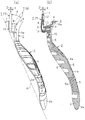
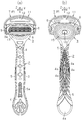
図1(a)及び図1(b)に示すホルダ1は、上下方向Zに沿って細長く延設された把持部2と、その把持部2の上端部に設けられた頭部3とを有している。図2(a)及び図2(b)に示すように、把持部2は、硬質樹脂により成形された主体部4と、軟質樹脂またはゴム材またはゴム材以外の軟質材により成形されてその主体部4の外側に露出する指当部5とを有している。図3(a)に示すように、把持部2の正面のほぼ全域には主体部4が露出し、その正面の下部には指当部5の一部5aが露出している。図3(b)に示すように、把持部2の背面側のほぼ全域には指当部5が露出し、その背面側の中間部及び下端部には主体部4の一部4aが露出している。図2(a)に示すように、把持部2の側面のほぼ全域には指当部5が露出し、その側面の下端部には主体部4の一部4aが露出している。頭部3は、硬質樹脂により把持部2の主体部4とともに主体部4と同一材料で一体成形された支持部6を有している。支持部6は、把持部2の上端部で主体部4に連続し、左側及び右側へ膨らんでいる。
The holder 1 shown in FIGS. 1 (a) and 1 (b) has a grip portion 2 elongated in the vertical direction Z and a head 3 provided at the upper end of the grip portion 2. is doing. As shown in FIGS. 2 (a) and 2 (b), the grip portion 2 includes a main body 4 formed of a hard resin and a main body formed of a soft resin, a rubber material, or a soft material other than a rubber material. And a finger holder 5 exposed to the outside of the portion 4. As shown in FIG. 3A, the main body 4 is exposed in almost the entire area of the front surface of the grip portion 2, and a part 5a of the finger holder 5 is exposed in the lower part of the front surface. As shown in FIG. 3 (b), the finger holding part 5 is exposed in almost the entire area on the back side of the grip part 2, and a part 4a of the main body part 4 is exposed in the intermediate part and the lower end part on the back side. ing. As shown in FIG. 2 (a), the finger holding part 5 is exposed over almost the entire side surface of the grip part 2, and a part 4a of the main body part 4 is exposed at the lower end part of the side surface. The head 3 includes a support portion 6 that is integrally formed of the same material as that of the main body 4 together with the main body 4 of the gripping section 2 using a hard resin. The support portion 6 is continuous with the main portion 4 at the upper end portion of the grip portion 2 and swells to the left and right sides.
図4、図5及び図6から明らかなように、頭部3の支持部6には上辺部、下辺部、左辺部、及び右辺部により略四角形の環状に形成された環状部6aが設けられている。上辺部、下辺部、左辺部、及び右辺部はそれぞれ外側へ膨らむ緩やかな曲線に沿って形成され、上辺部と左辺部との間の隅部や、上辺部と右辺部との間の隅部や、下辺部と左辺部との間の隅部や、下辺部と右辺部との間の隅部も、緩やかな曲線に沿って外側へ膨らんで、上辺部、下辺部、左辺部、及び右辺部に滑らかに連続している。ちなみに、上辺部及び下辺部の内側で左辺部と右辺部との間の最大の間隔は約28mmに設定され、左辺部及び右辺部の内側で上辺部と下辺部との間の最大の間隔は約23mmに設定されている。
As is apparent from FIGS. 4, 5, and 6, the support portion 6 of the head 3 is provided with an annular portion 6 a that is formed in a substantially square annular shape by an upper side portion, a lower side portion, a left side portion, and a right side portion. ing. The upper side, the lower side, the left side, and the right side are each formed along a gentle curve that bulges outward, and a corner between the upper side and the left side, or a corner between the upper side and the right side. The corner between the lower side and the left side and the corner between the lower side and the right side also bulge outward along a gentle curve, and the upper side, the lower side, the left side, and the right side. The part is smoothly continuous. Incidentally, the maximum distance between the left side and the right side inside the upper side and the lower side is set to about 28 mm, and the maximum distance between the upper side and the lower side inside the left side and the right side is It is set to about 23 mm.
図1(a)及び図1(b)に示す剃刀ヘッド7は、図2(a)に示すように、頭部3の正面に対して間隔Wをおいて首振り機構Mによって取り付けられている。剃刀ヘッド7の下側にはキャップ7aが下方から上方へ着脱可能に嵌め込まれる。
The razor head 7 shown in FIGS. 1 (a) and 1 (b) is attached by a swing mechanism M at an interval W with respect to the front surface of the head 3 as shown in FIG. 2 (a). . A cap 7a is detachably fitted to the lower side of the razor head 7 from below to above.
剃刀ヘッド7は、図2(b)、図3(a)及び図3(b)に示すように、刃体9を組み付けた刃体組付部8と、その刃体組付部8の裏側から頭部3の支持部6に向けて延びる被支持部10と、刃体組付部8が嵌め込まれて刃体組付部8の上下左右の外周を囲う枠体部11とを有している。刃体9の刃先9aは刃体組付部8の表側に露出している。枠体部11の上側及び下側にはシェービングエイド12,13がそれぞれ設けられている。
As shown in FIGS. 2B, 3A, and 3B, the razor head 7 includes a blade assembly portion 8 to which the blade body 9 is assembled, and the back side of the blade assembly portion 8. A supported portion 10 extending from the head 3 toward the support portion 6 of the head 3 and a frame body portion 11 into which the blade assembly portion 8 is fitted and encloses the upper, lower, left and right outer peripheries of the blade assembly portion 8. Yes. The blade edge 9 a of the blade body 9 is exposed on the front side of the blade body assembly portion 8. Shaving aids 12 and 13 are respectively provided on the upper side and the lower side of the frame body part 11.
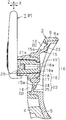
図2(a)、図2(b)及び図4~図6に示すように、頭部3において支持部6の環状部6aの内周と、剃刀ヘッド7の被支持部10の外周との間の支持孔14には、首振り機構Mとして、弾性板15(弾性部)が介在されている。支持部6の環状部6aの頂部は、上下方向Zに沿い、剃刀ヘッド7の刃体組付部8の上端部とほぼ同一の高さ位置に配置され、枠体部11の頂部が環状部6aの頂部より上方へ突出している。
2 (a), 2 (b) and FIGS. 4 to 6, the head 3 has an inner periphery of the annular portion 6a of the support portion 6 and an outer periphery of the supported portion 10 of the razor head 7 as shown in FIG. An elastic plate 15 (elastic portion) is interposed as a swing mechanism M in the support hole 14 therebetween. The top part of the annular part 6a of the support part 6 is arranged along the vertical direction Z at substantially the same height as the upper end part of the blade assembly part 8 of the razor head 7, and the top part of the frame part 11 is an annular part. It protrudes upward from the top of 6a.
剃刀ヘッド7の被支持部10は、筒部17と底部18とを有する第1連結部16と、刃体組付部8から突出する第2連結部19とからなる。第1連結部16の筒部17は上壁部、下壁部、左壁部、及び右壁部により四角筒状に形成されている。第2連結部19も上壁部、下壁部、左壁部、右壁部、及び底部18により有底四角筒状に形成されている。図5に示すように、第1連結部16内には剃刀ヘッド7の刃体組付部8に向かって開口された連結孔20が形成され、その連結孔20は底部18において窓口18aにより開放されている。底部18には窓口18aから刃体組付部8へ向けて前後方向Xに沿って延びる片持ち梁状の左右の係止腕部21が形成されている。第2連結部19の左右両壁部には係止孔22が形成されている。ちなみに、第1連結部16の筒部17の左右方向Yに沿った外形寸法は約19mmに設定され、第1連結部16の筒部17の上下方向Zに沿った外形寸法は約12mmに設定されている。
The supported portion 10 of the razor head 7 includes a first connecting portion 16 having a cylindrical portion 17 and a bottom portion 18 and a second connecting portion 19 protruding from the blade assembly portion 8. The cylindrical portion 17 of the first connecting portion 16 is formed in a square cylindrical shape by an upper wall portion, a lower wall portion, a left wall portion, and a right wall portion. The second connecting portion 19 is also formed in a bottomed rectangular tube shape by the upper wall portion, the lower wall portion, the left wall portion, the right wall portion, and the bottom portion 18. As shown in FIG. 5, a connecting hole 20 is formed in the first connecting portion 16 so as to open toward the blade assembly portion 8 of the razor head 7, and the connecting hole 20 is opened at the bottom 18 by a window 18 a. Has been. On the bottom portion 18, left and right locking arm portions 21 in the form of cantilevers extending along the front-rear direction X from the window 18 a toward the blade assembly portion 8 are formed. Locking holes 22 are formed in the left and right wall portions of the second connecting portion 19. Incidentally, the external dimension along the left-right direction Y of the cylindrical part 17 of the first connecting part 16 is set to about 19 mm, and the external dimension along the vertical direction Z of the cylindrical part 17 of the first connecting part 16 is set to about 12 mm. Has been.
第2連結部19は前記第1連結部16の連結孔20に挿入される。その挿入状態で、第2連結部19は筒部17の延設方向に沿う軸線16aを中心に回動しない状態で、その軸線16aに沿った方向のみに案内されながら、第1連結部16の連結孔20、即ち、結合部に挿着される。第2連結部19の底部は、第1連結部16の底部18に当接されて前後方向Xへの移動が規制されるとともに、その底部18の窓口18aから露出してその底部18と略面一になっている。第1連結部16の左右の係止腕部21、即ち、結合部はそれらの係止鉤部21aで第2連結部19の左右の係止孔22、即ち、結合部に係入され、第1連結部16からの第2連結部19の不用意な離脱が阻止されている。そのため、第1及び第2連結部16,19は互いに着脱不能になる。なお、第1及び第2連結部16,19を互いに着脱可能に構成してもよい。第1連結部16の筒部17及び底部18や、第1連結部16の左右の係止腕部21も、硬質樹脂により成形されている。
The second connecting part 19 is inserted into the connecting hole 20 of the first connecting part 16. In the inserted state, the second connecting portion 19 does not rotate around the axis 16a along the extending direction of the cylindrical portion 17 and is guided only in the direction along the axis 16a, while the second connecting portion 19 The coupling hole 20 is inserted into the coupling portion. The bottom portion of the second connecting portion 19 is brought into contact with the bottom portion 18 of the first connecting portion 16 to restrict movement in the front-rear direction X, and is exposed from the window 18a of the bottom portion 18 so as to be substantially flush with the bottom portion 18. It is one. The left and right latching arm portions 21 of the first connecting portion 16, that is, the coupling portions are engaged with the left and right latching holes 22 of the second coupling portion 19, that is, the coupling portions, with the latching flange portions 21 a. Inadvertent detachment of the second connecting portion 19 from the first connecting portion 16 is prevented. Therefore, the first and second connecting portions 16 and 19 cannot be attached to and detached from each other. In addition, you may comprise the 1st and 2nd connection parts 16 and 19 so that attachment or detachment is mutually possible. The cylindrical portion 17 and the bottom portion 18 of the first connecting portion 16 and the left and right engaging arm portions 21 of the first connecting portion 16 are also formed of hard resin.
弾性板15は、頭部3の支持部6と剃刀ヘッド7における被支持部10の第1連結部16とをインサートした金型内のキャビティに、指当部5と同じ材料(軟質樹脂またはゴム材またはゴム材以外の軟質材)を供給して、指当部5と一体成形されている。弾性板15は、支持孔14において支持部6の環状部6aの内周と連結部16の筒部17の外周とに沿って環状に連続する環状部15aを有している。指当部5には滑り止め機能を持たせたり感触を良くしたりするための各種形状の凹凸が形成されている。例えば、この弾性板15及び指当部5はスチレン系熱可塑性エラストマからなり、20以上60以下の範囲のショアA硬度を有している。
The elastic plate 15 is made of the same material (soft resin or rubber) as that of the finger holder 5 in a cavity in a mold in which the support portion 6 of the head 3 and the first connecting portion 16 of the supported portion 10 of the razor head 7 are inserted. A soft material other than a material or a rubber material) is supplied and is integrally formed with the finger holder 5. The elastic plate 15 has an annular portion 15 a that is annularly continuous along the inner periphery of the annular portion 6 a of the support portion 6 and the outer periphery of the cylindrical portion 17 of the connecting portion 16 in the support hole 14. The finger holder 5 is provided with irregularities of various shapes for providing an anti-slip function and improving the feel. For example, the elastic plate 15 and the finger holder 5 are made of a styrene-based thermoplastic elastomer and have a Shore A hardness in the range of 20 to 60.
このような弾性板15の成形後に、前述したように刃体組付部8が被支持部10に挿着される。環状部15aの外周部は支持部6の環状部6aの内周部に面接触されて、成形時の熱や圧力により環状部6aに取着されている。被支持部10は、環状部15aをその厚み方向(前後方向X)に沿って貫通した状態で、その環状部15aの表側及び裏側の間に支持されている。環状部15aの内周部は被支持部10の筒部17の外周部に面接触されて、成形時の熱や圧力により、被支持部10に取着されている。環状部15aには撓み許容部23が形成されている。撓み許容部23は、筒部17の延設方向に沿う軸線16aの外周で環状に連続して延びる突条部24と、その突条部24の内側で環状に連続して延びる溝部25とを有している。弾性板15は、支持部6の環状部6aと剃刀ヘッド7の被支持部10との間の支持孔14において、環状部6aの前後の内周縁部で区画された内側領域S内に配置されている。剃刀ヘッド7の被支持部10において、第1連結部16の底部18及び第2連結部19の底部は、刃体組付部8の反対側において、支持孔14の内側領域S内に配置されている。
After forming the elastic plate 15, the blade assembly part 8 is inserted into the supported part 10 as described above. The outer peripheral portion of the annular portion 15a is in surface contact with the inner peripheral portion of the annular portion 6a of the support portion 6, and is attached to the annular portion 6a by heat and pressure during molding. The supported portion 10 is supported between the front side and the back side of the annular portion 15a in a state of penetrating the annular portion 15a along the thickness direction (front-rear direction X). The inner peripheral portion of the annular portion 15a is in surface contact with the outer peripheral portion of the cylindrical portion 17 of the supported portion 10, and is attached to the supported portion 10 by heat and pressure during molding. A bending allowance portion 23 is formed in the annular portion 15a. The bendable portion 23 includes a ridge portion 24 continuously extending in an annular shape on the outer periphery of the axis 16 a along the extending direction of the cylindrical portion 17, and a groove portion 25 extending continuously in an annular shape inside the ridge portion 24. Have. The elastic plate 15 is disposed in the inner region S defined by the inner peripheral edge portions before and after the annular portion 6a in the support hole 14 between the annular portion 6a of the support portion 6 and the supported portion 10 of the razor head 7. ing. In the supported portion 10 of the razor head 7, the bottom portion 18 of the first connecting portion 16 and the bottom portion of the second connecting portion 19 are disposed in the inner region S of the support hole 14 on the opposite side of the blade assembly portion 8. ing.
撓み許容部23の突条部24は、刃体組付部8から離れるように軸線16aに沿って突出しているが、逆に刃体組付部8に接近するように軸線16aに沿って突出させてもよい。環状部15aを含む弾性板15は、略均一の厚み(0.1~3mm)を有している。弾性板15の環状部15aにおいて撓み許容部23の厚みを撓み許容部23以外の部分の厚みよりも小さくして、撓み易くしてもよい。撓み許容部23において突条部24の突出寸法は0.3~5mmである。
The protruding portion 24 of the bending allowance portion 23 protrudes along the axis 16a so as to be separated from the blade assembly portion 8, but conversely protrudes along the axis 16a so as to approach the blade assembly portion 8. You may let them. The elastic plate 15 including the annular portion 15a has a substantially uniform thickness (0.1 to 3 mm). In the annular portion 15 a of the elastic plate 15, the thickness of the bending allowance portion 23 may be made smaller than the thickness of the portion other than the bending allowance portion 23 to facilitate bending. In the bending allowance portion 23, the protruding dimension of the protruding portion 24 is 0.3 to 5 mm.
弾性板15の撓み許容部23は、図4において二点鎖線で区分したように、剃刀ヘッド7における刃体9の刃先9aの延設方向、即ち左右方向Zに沿って互いに対向して位置する左側及び右側の第1及び第2区分26a,26bと、刃先9aの延設方向に対して交差する上下方向Zに沿うように対向して位置する上側及び下側の第3、第4区分27,28と、左側及び右側の第1、第2区分26a,26bと上側の第3区分27との間に配置された第5区分29a,29bと、左側及び右側の第1、第2区分26a,26bと下側の第4区分28との間に位置する第6区分30a,30bとを有している。
The deflection allowing portions 23 of the elastic plate 15 are positioned so as to face each other along the extending direction of the cutting edge 9a of the blade body 9 in the razor head 7, that is, the left-right direction Z, as divided by a two-dot chain line in FIG. The first and second sections 26a and 26b on the left and right sides, and the upper and lower third and fourth sections 27 that face each other along the vertical direction Z that intersects the extending direction of the cutting edge 9a. 28, left and right first and second sections 26a, 26b and upper third section 27, and left and right first and second sections 26a. , 26b and the lower fourth section 28, the sixth sections 30a, 30b.
支持孔14において、支持部6の環状部6aの内周形状と被支持部10の第1連結部16の外周形状とは略相似形状をなしている。支持部6の上辺部と第1連結部16の上壁部との間の間隔(約6mm)は、支持部6の下辺部と第1連結部16の下壁部との間の間隔(約4mm)より大きく設定されている。支持部6の左辺部と第1連結部16の左壁部との間の間隔(約4mm)と、支持部6の右辺部と第1連結部16の右壁部との間の間隔(約4mm)とは、互いに略等しく設定されている。撓み許容部23の各区分26a,26b,27,28,29a,29b,30a,30bは互いに隣接して配設され、一体に形成されている。なお、各区分26a,26b,27,28,29a,29b,30a,30bはそれぞれ独立して形成されてもよい。
In the support hole 14, the inner peripheral shape of the annular portion 6 a of the support portion 6 and the outer peripheral shape of the first connecting portion 16 of the supported portion 10 are substantially similar. An interval (about 6 mm) between the upper side portion of the support portion 6 and the upper wall portion of the first connection portion 16 is an interval (about about 6 mm) between the lower side portion of the support portion 6 and the lower wall portion of the first connection portion 16. 4 mm). The distance (about 4 mm) between the left side part of the support part 6 and the left wall part of the 1st connection part 16, and the space | interval (about about the right side part of the support part 6 and the right wall part of the 1st connection part 16). 4 mm) is set substantially equal to each other. The sections 26a, 26b, 27, 28, 29a, 29b, 30a, 30b of the bending allowance portion 23 are disposed adjacent to each other and are integrally formed. Each section 26a, 26b, 27, 28, 29a, 29b, 30a, 30b may be formed independently.
図2(a)に示すように、前記ホルダ1において、頭部3は、側方から見て、正面から背面へ向かって把持部2の上端部から上方へ屈曲して延設されている。また、頭部3は、背面から正面に向かって膨らむように湾曲し、把持部2は、上端部と下端部との間の中間部において、背面から正面へ向かって下方へ屈曲して延設され、正面から背面に向かって膨らむように湾曲している。そのため、頭部3の側方から見て背面には凹み3aが形成され、把持部2の側方から見て正面には凹み2aが形成され、それらの凹み3a,2aにより、ホルダ1の全体が側方から見て滑らかに連続するS字状に湾曲している。把持部2の側方から見て上端部に対する頭部3の屈曲角度α(15度以上60度以下)は、把持部2の中間部における屈曲角度β(5度以上45度以下)より大きく設定されている。前記弾性板15は頭部3に沿って湾曲している。
As shown in FIG. 2 (a), in the holder 1, the head 3 is bent and extended upward from the upper end of the grip 2 from the front to the back as viewed from the side. The head 3 is curved so as to swell from the back to the front, and the grip 2 is bent and extended downward from the back to the front at an intermediate portion between the upper end and the lower end. It is curved so as to swell from the front to the back. Therefore, a recess 3a is formed on the back surface when viewed from the side of the head 3, and a recess 2a is formed on the front surface when viewed from the side of the grip portion 2, and the entire holder 1 is formed by these recesses 3a and 2a. Is curved in an S-shape that is smoothly continuous when viewed from the side. The bending angle α (15 ° to 60 °) of the head 3 with respect to the upper end when viewed from the side of the gripping portion 2 is set to be larger than the bending angle β (5 ° to 45 °) at the intermediate portion of the holding portion 2. Has been. The elastic plate 15 is curved along the head 3.
頭部3の弾性板15は前述したように湾曲しているため、弾性板15の撓み許容部23における各区分26a,26b,27,28,29a,29b,30a,30bにおいて、それらの断面形態や長さが互いに異なる。従って、弾性板15の撓み許容部23の各区分26a,26b,27,28,29a,29b,30a,30bの変形のし難さを指す難変形度(弾性度)についても、下記のように互いに異なる。
Since the elastic plate 15 of the head 3 is curved as described above, in each of the sections 26a, 26b, 27, 28, 29a, 29b, 30a, 30b in the bending allowance portion 23 of the elastic plate 15, their cross-sectional forms. And different lengths. Accordingly, the degree of deformation (elasticity) indicating the difficulty of deformation of each section 26a, 26b, 27, 28, 29a, 29b, 30a, 30b of the bending allowance portion 23 of the elastic plate 15 is as follows. Different from each other.
弾性板15の撓み許容部23において、左側及び右側の第1及び第2区分26a,26bは同じ難変形度を有しているが、刃先9aに近い下側における第4区分28の難変形度は、刃先9aから遠い上側における第3区分27の難変形度より高くなっている。また、下側の第4区分28の左側及び右側に並ぶ第6区分30a,30bの難変形度は、上側の第3区分27の左側及び右側に並ぶ第5区分29a,29bの難変形度より高くなっている。さらに、第5及び第6区分29a,29b,30a,30bの難変形度は、第1及び第2区分26a,26bの難変形度や第3及び第4区分27,28の難変形度よりも高くなっている。
In the bending allowance portion 23 of the elastic plate 15, the first and second sections 26a and 26b on the left side and the right side have the same degree of difficulty, but the degree of difficulty of the fourth section 28 on the lower side near the blade edge 9a. Is higher than the degree of hard deformation of the third section 27 on the upper side far from the blade edge 9a. The degree of difficulty of the sixth sections 30a and 30b arranged on the left and right sides of the lower fourth section 28 is more difficult than the degree of difficulty of the fifth sections 29a and 29b arranged on the left and right sides of the upper third section 27. It is high. Furthermore, the hard deformation degree of the fifth and sixth sections 29a, 29b, 30a, 30b is higher than the hard deformation degree of the first and second sections 26a, 26b and the hard deformation degree of the third and fourth sections 27, 28. It is high.
次に、首振り式剃刀の作用、即ち、剃刀の使用時の首振り動作について説明する。
Next, the action of the swinging razor, that is, the swinging operation when using the razor will be described.
剃刀ヘッド7は弾性板15により、図2(a)、図2(b)及び図4~図6に示す中立位置Pに保持される。その中立位置Pでは、剃刀ヘッド7の被支持部10において第1連結部16の底部18及び第2連結部19の底部が、刃体組付部8の反対側において、支持孔14の内側領域S内に配置される。頭部3の正面と剃刀ヘッド7の裏側との間隔Wについては、刃先9aの近傍において下方から上方へ向かって増加している。
The razor head 7 is held by the elastic plate 15 at a neutral position P shown in FIGS. 2 (a), 2 (b) and FIGS. 4 to 6. FIG. In the neutral position P, the bottom portion 18 of the first connecting portion 16 and the bottom portion of the second connecting portion 19 in the supported portion 10 of the razor head 7 are located in the inner region of the support hole 14 on the opposite side of the blade assembly portion 8. S. About the space | interval W of the front of the head 3 and the back side of the razor head 7, it has increased toward the upper direction from the downward direction in the vicinity of the blade edge | tip 9a.
使用時にその中立位置Pで剃刀ヘッド7の刃体組付部8や枠体部11などに力が加えられると、剃刀ヘッド7において刃体組付部8と被支持部10とは一体となって移動して弾性板15を押圧する。弾性板15は、複数の方向に撓んで、剃刀ヘッド7を移動させる。例えば、弾性板15は、上下方向Z、被支持部10の筒部17の軸線16aに沿った前後方向X、その軸線16aに交差する左右方向Y、左右方向Yに沿った軸線を中心に回動する方向、上下方向Zに沿った軸線を中心に回動する方向、前後方向X、左右方向Y、及び上下方向Zを組み合わせた方向へ撓み得る。従って、剃刀ヘッド7は中立位置Pから弾性板16の弾性に抗して三次元方向に複数の移動位置へ移動可能である。
When force is applied to the blade assembly portion 8 or the frame body portion 11 of the razor head 7 at the neutral position P during use, the blade assembly portion 8 and the supported portion 10 are integrated with each other in the razor head 7. To move and press the elastic plate 15. The elastic plate 15 is bent in a plurality of directions to move the razor head 7. For example, the elastic plate 15 rotates around the vertical direction Z, the front-rear direction X along the axis 16a of the cylindrical portion 17 of the supported portion 10, the left-right direction Y intersecting the axis 16a, and the axis along the left-right direction Y. The direction of movement, the direction of rotation about the axis along the up-down direction Z, the front-rear direction X, the left-right direction Y, and the up-down direction Z can be deflected. Therefore, the razor head 7 can move from the neutral position P to a plurality of movement positions in the three-dimensional direction against the elasticity of the elastic plate 16.
例えば、剃刀ヘッド7が上方へ傾動する場合や、剃刀ヘッド7が下方へ傾動する場合には、撓み許容部23の上側及び下側の第3及び第4区分27,28が主に変形する。また、例えば、剃刀ヘッド7が後方へ押された場合には、撓み許容部23の上側及び下側の第3及び第4区分27,28と、左側及び右側の第1及び第2区分26a,26bが主に変形する。また、例えば、剃刀ヘッド7が右方へ傾動する場合や、剃刀ヘッド7が左方へ傾動する場合には、左側及び右側の第1及び第2区分26a,26bが主に変形する。それらの場合に、第5及び第6区分29a,29b,30a,30bは第3及び第4区分27,28及び第1及び第2区分26a,26bよりも変形しにくい。しかも、撓み許容部23の各区分26a,26b,27,28,29a,29b,30a,30bの形態は変形が進むにつれて、それ以上の変形がしにくい形態に変化する。そのため、撓み許容部23の各区分26a,26b,27,28,29a,29b,30a,30bにおける複数の移動位置での難変形度は、中立位置Pにおける難変形度より高くなる。また、撓み許容部23の各区分26a,26b,27,28,29a,29b,30a,30bの難変形度は、剃刀ヘッド7が中立位置Pから複数の移動位置に移動するに従って高くなる。
For example, when the razor head 7 tilts upward or when the razor head 7 tilts downward, the upper and lower third and fourth sections 27 and 28 of the bending allowance portion 23 are mainly deformed. Further, for example, when the razor head 7 is pushed rearward, the upper and lower third and fourth sections 27 and 28 of the bending allowance portion 23, and the left and right first and second sections 26 a, 26b is mainly deformed. Further, for example, when the razor head 7 tilts to the right or when the razor head 7 tilts to the left, the left and right first and second sections 26a and 26b are mainly deformed. In those cases, the fifth and sixth sections 29a, 29b, 30a, 30b are less likely to deform than the third and fourth sections 27, 28 and the first and second sections 26a, 26b. Moreover, the shape of each section 26a, 26b, 27, 28, 29a, 29b, 30a, 30b of the bending allowance portion 23 changes to a form in which further deformation is difficult as the deformation progresses. Therefore, the degree of hard deformation at a plurality of moving positions in each of the sections 26a, 26b, 27, 28, 29a, 29b, 30a, and 30b of the bending allowance portion 23 is higher than the degree of hard deformation at the neutral position P. Further, the difficulty of deformation of each section 26a, 26b, 27, 28, 29a, 29b, 30a, 30b of the bending allowance portion 23 increases as the razor head 7 moves from the neutral position P to a plurality of movement positions.
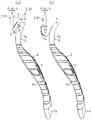
例えば、図7(a)は、同図に二点鎖線で示す中立位置Pから実線で示す移動位置Qへ移動した剃刀ヘッド7を示す。剃刀ヘッド7の裏側が中立位置Pから頭部3の正面に向けて30度以上移動して頭部3の正面に当たると、剃刀ヘッド7が移動位置Qにて停止される。この間の移動範囲は角度θで示されている。移動位置Qにおいて、頭部3の正面と剃刀ヘッド7の裏側との間隔Wは、中立位置Pとは異なり、刃先9aの近傍において下方から上方へ向かって減少している。
For example, FIG. 7A shows the razor head 7 moved from the neutral position P indicated by the two-dot chain line to the movement position Q indicated by the solid line in FIG. When the back side of the razor head 7 moves 30 degrees or more from the neutral position P toward the front of the head 3 and hits the front of the head 3, the razor head 7 is stopped at the movement position Q. The moving range during this time is indicated by an angle θ. In the movement position Q, the interval W between the front surface of the head 3 and the back side of the razor head 7 is different from the neutral position P, and decreases from below to above in the vicinity of the blade edge 9a.
なお、被支持部10や弾性板15を頭部3の背側から指で押さえて剃刀を使用すると、使用者の意図に合わせて剃刀ヘッド7の首振りを抑制することができる。
In addition, when the supported portion 10 and the elastic plate 15 are pressed with a finger from the back side of the head 3 and a razor is used, the swinging of the razor head 7 can be suppressed according to the user's intention.
一方、図7(b)に示すように、剃刀ヘッド7にその下方からキャップ7aを被せた場合にも、キャップ7aと頭部3の支持部6との間の隙間の範囲内でのみ、剃刀ヘッド7が移動し得る。キャップ7aを被せた剃刀ヘッド7の移動範囲は、キャップ7aを被せない剃刀ヘッド7の移動範囲より小さい。剃刀ヘッド7にその上方からキャップ7aを被せることもできる。
On the other hand, as shown in FIG. 7B, even when the razor head 7 is covered with the cap 7a from below, only within the range of the gap between the cap 7a and the support portion 6 of the head 3 is a razor. The head 7 can move. The movement range of the razor head 7 covered with the cap 7a is smaller than the movement range of the razor head 7 not covered with the cap 7a. The razor head 7 can be covered with a cap 7a from above.
また、図2(a)に示すように、剃刀ヘッド7を中立位置Pに配置した状態で、ホルダ1の把持部2が載置面Hに載置される時、剃刀ヘッド7の表面は載置面Hから離間しており、その状態で剃刀ヘッド7と載置面Hとがなす角度γは20度以上に設定されている。
Further, as shown in FIG. 2A, when the grip portion 2 of the holder 1 is placed on the placement surface H with the razor head 7 placed at the neutral position P, the surface of the razor head 7 is placed. The angle γ formed by the razor head 7 and the placement surface H in this state is set to 20 degrees or more.
本実施形態は下記の効果を有する。
This embodiment has the following effects.
(1)剃刀ヘッド7の裏側を頭部3の正面に対して間隔Wをあけて対向させて取り付けたので、身体の各部に生える膚毛を剃る場合に、ホルダ1を把持した手を大きく屈曲させなくても、剃刀ヘッド7の表側を身体の皮膚面に沿わせて剃刀を使用することができ、剃刀の使い勝手を良くすることができる。また、剃刀ヘッド7の裏側とホルダ1の頭部3の正面との間の間隔Wを設けたので、剃刀ヘッド7の表側を身体の皮膚面に沿わせて剃刀を使用する際に、頭部3の正面が身体の皮膚面に接触しにくくなって、剃刀の使い勝手をより一層良くすることができる。
(1) Since the back side of the razor head 7 is attached facing the front surface of the head 3 with a gap W, the hand holding the holder 1 is bent greatly when shaving the hair growing on each part of the body. Even if the razor head is not used, the razor can be used with the front side of the razor head 7 along the skin surface of the body, and the usability of the razor can be improved. In addition, since a gap W is provided between the back side of the razor head 7 and the front surface of the head 3 of the holder 1, when using the razor with the front side of the razor head 7 along the skin surface of the body, The front face of 3 is less likely to come into contact with the skin surface of the body, and the usability of the razor can be further improved.
(2)ホルダ1の頭部3は側方から見て、正面から背面へ向かい、把持部2の上端部から上方へ屈曲して延設されているので、剃刀ヘッド7の裏側と頭部3の正面との間の間隔Wについては、刃先9aから上方へ向かって増加するように設定し易くなる。そのため、刃先9aよりも上方において剃刀ヘッド7の首振り範囲が広くなり、剃刀の使い勝手を良くすることができる。
(2) Since the head 3 of the holder 1 is viewed from the side, extending from the front to the back and bent upward from the upper end of the grip 2, the back of the razor head 7 and the head 3 It becomes easy to set about the space | interval W between the front side of this so that it may increase upwards from the blade edge | tip 9a. Therefore, the swing range of the razor head 7 becomes wider above the blade edge 9a, and the usability of the razor can be improved.
(3)頭部3の正面に対する剃刀ヘッド7の裏側の間隔Wを首振り機構Mにより変更して、剃刀ヘッド7の中立位置Pでは刃先9aから上方へ向かって増加するように設定し、中立位置Pから剃刀ヘッド7を移動させた所定の移動位置Qでは、刃先9aの近傍において下方から上方へ向かって減少させている。そのため、剃刀ヘッド7の首振り範囲が広くなり、剃刀の使い勝手を良くすることができる。
(3) The interval W on the back side of the razor head 7 with respect to the front surface of the head 3 is changed by the swing mechanism M, and is set so as to increase upward from the blade edge 9a at the neutral position P of the razor head 7. At a predetermined movement position Q where the razor head 7 is moved from the position P, the distance is decreased from below to above in the vicinity of the cutting edge 9a. Therefore, the swing range of the razor head 7 is widened, and the usability of the razor can be improved.
(4)ホルダ1の頭部3の支持部6と剃刀ヘッド7の被支持部10との間に介在させた弾性板15のみにより剃刀ヘッド7を支持している。そのため、剃刀ヘッド7を中立位置Pから弾性板15の弾性に抗して移動可能に支持する支持構造を簡単にすることができる。
(4) The razor head 7 is supported only by the elastic plate 15 interposed between the support portion 6 of the head 3 of the holder 1 and the supported portion 10 of the razor head 7. Therefore, it is possible to simplify the support structure that supports the razor head 7 so as to be movable from the neutral position P against the elasticity of the elastic plate 15.
(5)支持部6の環状部6aの内周部で弾性板15の環状部15aの外周部を支持するとともに、弾性板15の環状部15aの内周部に剃刀ヘッド7の被支持部10を挿着した簡単な支持構造により、使用時に剃刀ヘッド7を中立位置Pから弾性板15の弾性に抗して三次元方向の移動位置に移動させ得るばかりではなく、剃刀ヘッド7の使用時に弾性板15の環状部15aの弾性によるクッション機能が得られて、首振り式剃刀の使い勝手を良くすることができる。
(5) The outer peripheral portion of the annular portion 15a of the elastic plate 15 is supported by the inner peripheral portion of the annular portion 6a of the support portion 6, and the supported portion 10 of the razor head 7 is supported on the inner peripheral portion of the annular portion 15a of the elastic plate 15. The razor head 7 can be moved from the neutral position P to the moving position in the three-dimensional direction against the elasticity of the elastic plate 15 at the time of use. The cushion function by the elasticity of the annular portion 15a of the plate 15 is obtained, and the usability of the swing-type razor can be improved.
(6)弾性板15の環状部15aには円環状の突条部24及び溝部25を有する撓み許容部23を形成したので、弾性板15の環状部15aを三次元方向へ撓み易くすることができるばかりではなく、剃刀ヘッド7の使用時に撓み許容部23によるクッション機能をより一層効果的に得ることができる。しかも、撓み許容部23において円環状の突条部24が筒部17の軸線16aに沿う方向へ突出しているので、環状部15aは、軸線16aに直交する方向(左右方向Yや上下方向Zなど)よりも軸線16aに沿った方向(前後方向X)へ撓み易くなる。また、前後方向Xに延びる軸線16aに直交する軸線(左右方向Yや上下方向Zなどに延びる軸線)と、その軸線16aとの交点を中心点として、ボールジョイントなどのユニバーサルジョイントと同様な機能が得られるため、環状部15aはより一層三次元方向へ撓み易くなる。
(6) Since the bending portion 23 having the annular protrusion 24 and the groove 25 is formed in the annular portion 15a of the elastic plate 15, the annular portion 15a of the elastic plate 15 can be easily bent in the three-dimensional direction. In addition to being able to do so, the cushion function by the deflection allowing portion 23 can be obtained more effectively when the razor head 7 is used. In addition, since the annular protrusion 24 protrudes in the direction along the axis 16a of the cylindrical portion 17 in the bending allowance portion 23, the annular portion 15a is in a direction orthogonal to the axis 16a (such as the left-right direction Y and the up-down direction Z). ) In the direction along the axis 16a (front-rear direction X). Also, the same function as that of a universal joint such as a ball joint is performed with an axis line orthogonal to an axis line 16a extending in the front-rear direction X (an axis line extending in the left-right direction Y or the vertical direction Z) and the axis line 16a as a center point. As a result, the annular portion 15a is more easily bent in the three-dimensional direction.
(7)弾性板15の環状部15aには環状の突条部24及び溝部25を有する撓み許容部23が略四角形の環状に形成されているので、ボールジョイントなどのユニバーサルジョイントと同様な機能が得られるばかりでなく、撓み許容部23の第5及び第6区分29a,29b,30a,30bの難変形度を、第1及び第2区分26a,26bの難変形度や、第3及び第4区分27,28の難変形度より高くしたり、第4区分28の難変形度を第3区分27の難変形度より高くしたり、剃刀ヘッド7が中立位置Pから移動位置に移動するに従いそれらの難変形度を高くしたりすることができ、難変形度を適切に設定して剃り味を容易に変更することができる。
(7) Since the bending portion 23 having the annular protrusion 24 and the groove 25 is formed in the annular portion 15a of the elastic plate 15 in a substantially square annular shape, the same function as a universal joint such as a ball joint is provided. In addition to being obtained, the fifth and sixth sections 29a, 29b, 30a, and 30b of the bending allowance portion 23 have the hard deformation degrees, the hard deformation degrees of the first and second sections 26a and 26b, and the third and fourth sections. The degree of difficulty deformation of the sections 27 and 28 is increased, the degree of difficulty deformation of the fourth section 28 is made higher than the degree of difficulty deformation of the third section 27, and as the razor head 7 moves from the neutral position P to the movement position, The degree of hard deformation can be increased, and the degree of shaving can be easily changed by appropriately setting the degree of hard deformation.
前記実施形態以外にも例えば下記のように構成してもよい。
For example, the following embodiment may be configured as follows.
前記実施形態において、首振り機構Mを省略し、剃刀ヘッド7をホルダ1の頭部3に対し首振り不能に支持する。
In the above embodiment, the swing mechanism M is omitted, and the razor head 7 is supported on the head 3 of the holder 1 so as not to swing.
弾性部としては、ゴム材により成形した弾性板15以外に、発泡材や粘性体内包部材やコイルばねや板ばねなどを利用してもよい。また、硬質樹脂や金属により成形されたばねを利用してもよい。
As the elastic portion, in addition to the elastic plate 15 formed of a rubber material, a foamed material, a viscous inclusion member, a coil spring, a leaf spring, or the like may be used. Further, a spring formed of hard resin or metal may be used.
支持部6としては、円環状や四角形以外に、三角形や楕円形などの環状でもよく、また、環状以外に、一部が切り欠かれた例えばU状であってもよい。
The support portion 6 may have a ring shape such as a triangle or an ellipse in addition to the ring shape or the quadrangle shape, and may have a U shape with a part cut away.
弾性部としては、弾性板15の環状部15aに複数の貫通孔を設け、それらの貫通孔の間に複数の撓み許容区分を等間隔で環状に並設してもよい。また、例えば、弾性板15の上側、下側、左側、及び右側の各位置のうち、上側及び下側位置の二箇所、左側及び右側位置の二箇所、左側、右側及び上側位置の三箇所、あるいは、左側、右側、及び下側位置の三箇所に、撓み許容区分を設けてもよい。
As the elastic portion, a plurality of through holes may be provided in the annular portion 15a of the elastic plate 15, and a plurality of bending allowance sections may be arranged in an annular manner at equal intervals between the through holes. Further, for example, among the positions on the upper side, the lower side, the left side, and the right side of the elastic plate 15, two places on the upper side and the lower side position, two places on the left side and the right side position, three places on the left side, the right side, and the upper side position, Or you may provide a bending | flexion permissible division in three places, the left side, the right side, and a lower side position.
弾性部としては、支持部上で膨らむ半球状であってもよい。
The elastic part may be a hemispherical shape that swells on the support part.
弾性部に該当する部分を薄肉にしてより撓み易くしてもよい。
The part corresponding to the elastic part may be made thin to make it easier to bend.
環状の弾性板15において、厚みに変化を持たせたり、突条部24の形状を変更したり、弾性板15に対する被支持部10の支持位置を偏心させたりして、弾性板15の周囲で変形のし難さを指す難変形度(弾性度)を変えるようにしてもよい。
In the annular elastic plate 15, the thickness of the elastic plate 15 is changed, the shape of the protruding portion 24 is changed, or the support position of the supported portion 10 with respect to the elastic plate 15 is decentered. You may make it change the difficulty deformation degree (elasticity degree) which shows the difficulty of a deformation | transformation.
頭部3の支持部6と剃刀ヘッド7の被支持部10との間に一つまたは複数の薄板部を設けて、前後方向Xに沿う軸線16aを中心とする回動方向へ弾性板15の環状部15aが撓むことを規制してもよい。その薄板部を設けても、前後方向Xに沿う軸線16aを中心とする回動方向以外の方向へ弾性板15の環状部15aが撓むことは許容する。
One or a plurality of thin plate portions are provided between the support portion 6 of the head 3 and the supported portion 10 of the razor head 7, and the elastic plate 15 is rotated in the rotation direction about the axis 16 a along the front-rear direction X. The bending of the annular portion 15a may be restricted. Even if the thin plate portion is provided, the annular portion 15a of the elastic plate 15 is allowed to bend in a direction other than the rotation direction around the axis 16a along the front-rear direction X.
1…ホルダ、2…把持部、3…頭部、6…頭部の支持部、6a…支持部の環状部、7…剃刀ヘッド、8…刃体組付部、9…刃体、9a…刃先、10…剃刀ヘッドの被支持部、14…頭部の支持孔、15…頭部の弾性板(弾性部)、15a…弾性板の環状部、16,19…被支持部の第1及び第2連結部、20…被支持部の連結孔(結合部)、21…被支持部の係止腕部(結合部)、22…被支持部の係止孔(結合部)、23…弾性板の撓み許容部、26a…第1区分、26b…第2区分、27…第3区分、28…第4区分、29a,29b…第5区分、30a,30b…第6区分、M…首振り機構、W…間隔、P…中立位置、Q…移動位置、Y…刃先の延設方向(左右方向)、Z…上下方向。
DESCRIPTION OF SYMBOLS 1 ... Holder, 2 ... Holding part, 3 ... Head, 6 ... Support part of head, 6a ... Annular part of support part, 7 ... Razor head, 8 ... Blade assembly part, 9 ... Blade, 9a ... Cutting edge, 10 ... supported portion of razor head, 14 ... support hole in head, 15 ... elastic plate (elastic portion) in head, 15a ... annular portion of elastic plate, 16, 19 ... first of supported portion and 2nd connection part, 20 ... Connection hole (joint part) of supported part, 21 ... Locking arm part (joint part) of supported part, 22 ... Lock hole (joint part) of supported part, 23 ... Elasticity Plate bending allowance part, 26a ... 1st section, 26b ... 2nd section, 27 ... 3rd section, 28 ... 4th section, 29a, 29b ... 5th section, 30a, 30b ... 6th section, M ... swinging Mechanism, W ... interval, P ... neutral position, Q ... moving position, Y ... extending direction of the blade edge (left / right direction), Z ... up / down direction.
Claims (29)
- 把持部及びその把持部の上端に頭部を備えたホルダと、そのホルダの頭部の正面に取り付けた刃体を有する剃刀ヘッドとを備え、その剃刀ヘッドは刃体の刃先が露出する表側と、その表側とは反対の裏側とを有し、剃刀ヘッドの裏側と頭部の正面との間に間隔をあけた状態で、剃刀ヘッドを頭部に対向して配置したことを特徴とする剃刀。 A gripper and a holder having a head at the upper end of the gripper, and a razor head having a blade attached to the front of the head of the holder, the razor head having a front side on which the blade edge of the blade is exposed; The razor has a back side opposite to the front side, and the razor head is disposed opposite the head with a space between the back side of the razor head and the front of the head. .
- 前記ホルダの頭部には剃刀ヘッドを中立位置から頭部の正面に向けて移動させる首振り機構を設け、
剃刀ヘッドの中立位置において、前記剃刀ヘッドの裏側と頭部の正面との間の前記間隔は前記刃先の近傍から上方へ増加するように設定されていることを特徴とする請求項1に記載の剃刀。 The head of the holder is provided with a swing mechanism that moves the razor head from the neutral position toward the front of the head,
2. The neutral position of the razor head, wherein the distance between the back side of the razor head and the front surface of the head is set so as to increase upward from the vicinity of the cutting edge. razor. - 前記ホルダの頭部には剃刀ヘッドを中立位置から頭部の正面に向けて移動させる首振り機構を設け、
この頭部は、その正面から背面へ向かって把持部の上端から上方へ屈曲して延設されていることを特徴とする請求項1に記載の剃刀。 The head of the holder is provided with a swing mechanism that moves the razor head from the neutral position toward the front of the head,
The razor according to claim 1, wherein the head is bent and extended upward from the upper end of the grip portion from the front to the back. - 前記ホルダの頭部には剃刀ヘッドを中立位置から頭部の正面に向けて移動させる首振り機構を設け、
この首振り機構は、
前記剃刀ヘッドの裏側と頭部の正面との前記間隔を変更可能であり、
剃刀ヘッドの中立位置において、前記剃刀ヘッドの裏側と頭部の正面との間隔は、刃先の近傍において下方から上方へ向かって増加するように構成され、
前記中立位置から剃刀ヘッドを移動させる際に特定の移動位置まで移動可能であり、その特定の移動位置では、前記間隔が刃先の近傍において下方から上方へ向かって減少するように構成されている
ことを特徴とする請求項1に記載の剃刀。 The head of the holder is provided with a swing mechanism that moves the razor head from the neutral position toward the front of the head,
This swing mechanism
The distance between the back side of the razor head and the front of the head can be changed,
In the neutral position of the razor head, the interval between the back side of the razor head and the front surface of the head is configured to increase from below to above in the vicinity of the blade edge,
When the razor head is moved from the neutral position, the razor head can be moved to a specific movement position, and at the specific movement position, the interval is configured to decrease from below to above in the vicinity of the blade edge. The razor according to claim 1. - 前記ホルダの頭部は、刃体の刃先の左側及び右側に向かうように把持部の上端部から膨らむように構成されていることを特徴とする請求項1~4のうち何れか一項に記載の剃刀。 The head of the holder is configured to swell from the upper end of the gripping portion so as to be directed to the left and right sides of the blade edge of the blade body, according to any one of claims 1 to 4. Razor.
- 前記ホルダにおいて把持部は、上端部と下端部との間の中間部において、側方から見て背面から正面へ向かって下方へ屈曲して延設されていることを特徴とする請求項1~5のうち何れか一項に記載の剃刀。 The holding portion of the holder is extended at a middle portion between the upper end portion and the lower end portion by bending downward from the back to the front when viewed from the side. The razor according to any one of 5.
- 前記首振り機構は、ホルダの頭部に設けた支持部と、剃刀ヘッドに設けた被支持部と、前記支持部と被支持部との間に介在された弾性部とを有し、前記剃刀ヘッドはその弾性部により付勢されて静止する中立位置と、その中立位置から弾性部の付勢力に抗して移動した移動位置とを取り得ることを特徴とする請求項2~4のうち何れか一項に記載の剃刀。 The swing mechanism has a support portion provided on the head of the holder, a supported portion provided on the razor head, and an elastic portion interposed between the support portion and the supported portion, and the razor 5. The head according to any one of claims 2 to 4, wherein the head can take a neutral position urged by the elastic portion to be stationary and a moving position moved from the neutral position against the urging force of the elastic portion. The razor according to claim 1.
- 前記弾性部は、弾性板であって、前記頭部の支持部に支持された外周部を有し、弾性板の外周部よりも内側で剃刀ヘッドの被支持部を支持したことを特徴とする請求項7に記載の剃刀。 The elastic portion is an elastic plate, and has an outer peripheral portion supported by the support portion of the head, and supports the supported portion of the razor head inside the outer peripheral portion of the elastic plate. The razor according to claim 7.
- 前記頭部の支持部は環状に配設された環状部を有し、前記支持部の環状部の内周と前記剃刀ヘッドの被支持部の外周との間に支持孔が形成され、前記弾性部はその支持孔において環状に配設された環状部を有し、前記頭部はその背面から正面に向けて膨らむように湾曲し、前記弾性部の環状部は前記頭部に沿って湾曲していることを特徴とする請求項7または請求項8に記載の剃刀。 The support part of the head has an annular part arranged in an annular shape, and a support hole is formed between the inner periphery of the annular part of the support part and the outer periphery of the supported part of the razor head, and the elastic The portion has an annular portion disposed in an annular shape in the support hole, the head portion is curved so as to swell from the back surface toward the front surface, and the annular portion of the elastic portion is curved along the head portion. The razor according to claim 7 or 8, wherein the razor is provided.
- 前記弾性部は撓み許容部を有し、その撓み許容部は変形のし難さを指す難変形度の異なる複数の区分を有していることを特徴とする請求項7~9のうち何れか一項に記載の剃刀。 10. The elastic portion has a bending allowance portion, and the bending allowance portion has a plurality of sections having different degrees of difficulty indicating the difficulty of deformation. The razor according to one item.
- 前記弾性部の撓み許容部は、前記刃体の刃先の延設方向に対して交差する方向に沿うように対向して位置する上側及び下側の区分を有し、下側の区分の難変形度は上側の区分の難変形度より高く設定されていることを特徴とする請求項10に記載の剃刀。 The bending allowance portion of the elastic portion has upper and lower sections that face each other along a direction intersecting the extending direction of the blade edge of the blade body, and the lower section is difficult to deform. The razor according to claim 10, wherein the degree is set higher than the degree of hard deformation of the upper section.
- 前記弾性部は、剃刀ヘッドの中立位置において、支持部の環状部と剃刀ヘッドの被支持部との間の支持孔内に配置され、
前記剃刀ヘッドは前記刃体を組み込んだ組付部を有し、
前記剃刀ヘッドの被支持部は、前記弾性部を前記頭部の支持部との間に介在させる第1連結部と、前記組付部から延びる第2連結部と、第1及び第2連結部を互いに支持する結合部とを有し、
前記組付部とは反対側に位置する第1連結部の端部は、剃刀ヘッドの中立位置において、前記支持孔内に配置されていることを特徴とする請求項9に記載の剃刀。 The elastic portion is disposed in a support hole between the annular portion of the support portion and the supported portion of the razor head at a neutral position of the razor head,
The razor head has an assembly portion in which the blade body is incorporated,
The supported portion of the razor head includes a first connecting portion for interposing the elastic portion between the supporting portion of the head, a second connecting portion extending from the assembly portion, and first and second connecting portions. And a coupling part for supporting each other,
10. The razor according to claim 9, wherein an end portion of the first connecting portion located on a side opposite to the assembly portion is disposed in the support hole at a neutral position of the razor head. - 剃刀ヘッドが中立位置に配置された状態で、ホルダを載置面に載置した際に、剃刀ヘッドの表面と載置面との間に形成される傾斜角度は、20度以上に設定され、剃刀ヘッドが中立位置から頭部の正面に向けて移動した移動位置において剃刀ヘッドが頭部に当って停止するように設定されていることを特徴とする請求項2から4及び7から12の何れか一項に記載の剃刀。 When the holder is placed on the placement surface with the razor head placed in the neutral position, the inclination angle formed between the surface of the razor head and the placement surface is set to 20 degrees or more, The razor head is set so as to stop when it hits the head at a moving position where the razor head has moved from the neutral position toward the front of the head. The razor according to claim 1.
- 前記剃刀ヘッドは、剃刀ヘッドを中立位置に配置した状態で、ホルダを載置面に載置した際に、載置面から離間して配置されることを特徴とする請求項13に記載の剃刀。 The razor head according to claim 13, wherein the razor head is disposed apart from the placement surface when the holder is placed on the placement surface in a state where the razor head is located at the neutral position. .
- 前記首振り機構は、剃刀ヘッドが中立位置から頭部の正面に向けて30度以上移動して頭部に当って停止するように設定されていることを特徴とする請求項13または14に記載の剃刀。 15. The head swing mechanism is set so that the razor head moves 30 degrees or more from the neutral position toward the front of the head and stops by hitting the head. Razor.
- 前記把持部の側方から見て上端部に対する頭部の屈曲角度は、把持部の中間部における屈曲角度より大きく設定されていることを特徴とする請求項6に記載の剃刀。 The razor according to claim 6, wherein a bending angle of the head with respect to the upper end portion when viewed from the side of the gripping portion is set to be larger than a bending angle at an intermediate portion of the gripping portion.
- 前記頭部は側方から見て背面から正面に膨らむように湾曲し、前記把持部は側方から見て正面から背面に膨らむように湾曲して、ホルダの全体が側方から見てS字状に湾曲していることを特徴とする請求項6または16に記載の剃刀。 The head is curved so as to swell from the back to the front as viewed from the side, the gripping part is curved so as to swell from the front to the back as viewed from the side, and the entire holder is S-shaped as viewed from the side. The razor according to claim 6 or 16, wherein the razor is curved in a shape.
- 前記弾性部は前記頭部の支持部に支持された外周部を有していることを特徴とする請求項7に記載の剃刀。 The razor according to claim 7, wherein the elastic part has an outer peripheral part supported by a support part of the head.
- 前記弾性部はその弾性部の外周部よりも内側で剃刀ヘッドの被支持部を支持していることを特徴とする請求項18に記載の剃刀。 The razor according to claim 18, wherein the elastic portion supports the supported portion of the razor head inside the outer peripheral portion of the elastic portion.
- 前記弾性部は弾性板から構成されることを特徴とする請求項19に記載の剃刀。 The razor according to claim 19, wherein the elastic portion is formed of an elastic plate.
- 前記剃刀ヘッドの被支持部は弾性板の表側及び裏側のうち少なくとも一方に支持されることを特徴とする請求項19に記載の剃刀。 The razor according to claim 19, wherein the supported portion of the razor head is supported by at least one of the front side and the back side of the elastic plate.
- 前記頭部の支持部は環状に形成された環状部を有し、前記弾性部はその支持部の環状部の内周と前記剃刀ヘッドの被支持部の外周との間の支持孔内に環状に配設された環状部を有していることを特徴とする請求項7及び請求項18から21の何れか一項に記載の剃刀。 The support part of the head has an annular part formed in an annular shape, and the elastic part is annular in a support hole between the inner periphery of the annular part of the support part and the outer periphery of the supported part of the razor head. The razor according to any one of claims 7 and 18 to 21, wherein the razor has an annular portion disposed on the surface.
- 前記頭部は背面から正面に膨らむように湾曲し、前記弾性部はその頭部に沿って湾曲していることを特徴とする請求項22に記載の剃刀。 The razor according to claim 22, wherein the head is curved so as to swell from the back to the front, and the elastic portion is curved along the head.
- 前記弾性部の撓み許容部の各区分は互いに隣接して並設されていることを特徴とする請求項10または11に記載の剃刀。 The razor according to claim 10 or 11, wherein each section of the bending allowance portion of the elastic portion is arranged adjacent to each other.
- 前記弾性部の撓み許容部の各区分は剃刀ヘッドの被支持部の外周に環状に並設されていることを特徴とする請求項24に記載の剃刀。 25. The razor according to claim 24, wherein each section of the bending allowance portion of the elastic portion is arranged in a ring shape on the outer periphery of the supported portion of the razor head.
- 前記弾性部の撓み許容部は、剃刀ヘッドの中立位置から移動位置への移動に従って変形し、その撓み許容部の移動位置における難変形度は、撓み許容部の中立位置における難変形度より高く設定されていることを特徴とする請求項10、11及び25の何れか一項に記載の剃刀。 The bending allowance portion of the elastic portion is deformed in accordance with the movement from the neutral position of the razor head to the movement position, and the degree of difficulty deformation at the movement position of the bending allowance portion is set higher than the degree of difficulty deformation at the neutral position of the deflection permission portion. 26. The razor according to any one of claims 10, 11 and 25, wherein:
- 前記ホルダにおいて頭部は把持部と連続して設けられ、この把持部は頭部の弾性部と一体に成形されて露出する指当部を有していることを特徴とする請求項7から26の何れか一項に記載の剃刀。 27. The holder according to claim 7, wherein the holder has a head portion provided continuously with the gripping portion, and the gripping portion is formed integrally with the elastic portion of the head and has a finger contact portion that is exposed. The razor according to any one of the above.
- 前記弾性部は、剃刀ヘッドが中立位置に配置された状態で、支持部の環状部と剃刀ヘッドの被支持部との間の支持孔内に配置されることを特徴とする請求項22または23に記載の剃刀。 The elastic portion is disposed in a support hole between the annular portion of the support portion and the supported portion of the razor head in a state where the razor head is disposed in a neutral position. The razor described in 1.
- 前記剃刀ヘッドは前記刃体を組み込んだ組付部を有し、前記剃刀ヘッドの被支持部は、前記弾性部を前記頭部の支持部との間に介在させる第1連結部と、前記組付部から延びる第2連結部と、第1及び第2連結部を互いに支持する結合部とを有し、前記組付部とは反対側に位置する第1連結部の端部は、剃刀ヘッドの中立位置において前記支持孔内に配置されていることを特徴とする請求項28に記載の剃刀。 The razor head has an assembly portion in which the blade body is incorporated, and the supported portion of the razor head includes a first connecting portion that interposes the elastic portion with a support portion of the head, and the assembly. A second linking portion extending from the attachment portion; and a coupling portion for supporting the first and second linking portions with each other, and an end portion of the first linking portion located on the side opposite to the attachment portion is a razor head The razor according to claim 28, wherein the razor is disposed in the support hole in a neutral position.
Priority Applications (4)
| Application Number | Priority Date | Filing Date | Title |
|---|---|---|---|
| US14/439,066 US9796101B2 (en) | 2012-11-06 | 2013-11-05 | Razor |
| CN201380056966.0A CN104768719B (en) | 2012-11-06 | 2013-11-05 | Razor |
| ES13853531T ES2804549T3 (en) | 2012-11-06 | 2013-11-05 | Razor |
| EP13853531.5A EP2918383B1 (en) | 2012-11-06 | 2013-11-05 | Razor |
Applications Claiming Priority (2)
| Application Number | Priority Date | Filing Date | Title |
|---|---|---|---|
| JP2012244029A JP6093551B2 (en) | 2012-11-06 | 2012-11-06 | razor |
| JP2012-244029 | 2012-11-06 |
Publications (1)
| Publication Number | Publication Date |
|---|---|
| WO2014073500A1 true WO2014073500A1 (en) | 2014-05-15 |
Family
ID=50684605
Family Applications (1)
| Application Number | Title | Priority Date | Filing Date |
|---|---|---|---|
| PCT/JP2013/079813 WO2014073500A1 (en) | 2012-11-06 | 2013-11-05 | Razor |
Country Status (6)
| Country | Link |
|---|---|
| US (1) | US9796101B2 (en) |
| EP (1) | EP2918383B1 (en) |
| JP (1) | JP6093551B2 (en) |
| CN (1) | CN104768719B (en) |
| ES (1) | ES2804549T3 (en) |
| WO (1) | WO2014073500A1 (en) |
Cited By (2)
| Publication number | Priority date | Publication date | Assignee | Title |
|---|---|---|---|---|
| US9327415B1 (en) * | 2014-01-10 | 2016-05-03 | Tadhe Hovsepian | Interchangeable head size precision razor device |
| WO2019022043A1 (en) * | 2017-07-24 | 2019-01-31 | 株式会社貝印刃物開発センター | Oscillating razor |
Families Citing this family (17)
| Publication number | Priority date | Publication date | Assignee | Title |
|---|---|---|---|---|
| JP6093551B2 (en) * | 2012-11-06 | 2017-03-08 | 株式会社貝印刃物開発センター | razor |
| MX360046B (en) * | 2012-12-21 | 2018-10-19 | Bic Violex Sa | Shaver. |
| US10315322B1 (en) * | 2016-05-17 | 2019-06-11 | Dryfhout Properties, Llc | Method of using a back shaver handle |
| US10131062B1 (en) | 2014-01-31 | 2018-11-20 | Dryfhout Enterprises, Llc | Body shaver with comb and blade |
| US10500744B1 (en) | 2014-01-31 | 2019-12-10 | Dryfhout Properties, Llc | Safety razor with plurality of comb and integrated blade groups |
| US11077570B2 (en) * | 2014-01-31 | 2021-08-03 | Dryfhout Properties, Llc | Flexible back shaver |
| PL3110599T3 (en) * | 2014-02-28 | 2020-03-31 | Bic-Violex S.A. | A razor handle comprising inserts within holes and razor comprising such a razor handle |
| US9616584B2 (en) | 2014-03-20 | 2017-04-11 | Rolling Razor, Inc. | Shaving razor and shaving handle with an interconnection mechanism |
| US10807258B2 (en) * | 2014-07-31 | 2020-10-20 | Beiersdorf Ag | Safety razor and blade unit for safety razor |
| DE102016101672A1 (en) * | 2016-01-29 | 2017-08-03 | Beiersdorf Aktiengesellschaft | Nassrasiergriff |
| US10493643B1 (en) | 2016-05-17 | 2019-12-03 | Dryfhout Properties, Llc | Leveled back shaver |
| US20170334081A1 (en) * | 2016-05-17 | 2017-11-23 | Dryfhout Enterprises, Llc | Two-sided body shaver |
| US10543609B2 (en) | 2016-05-17 | 2020-01-28 | Dryfhout Properties, Llc | Elevated shaver |
| US10414058B2 (en) * | 2016-08-11 | 2019-09-17 | The Gillette Company Llc | Handle for a razor |
| USD835346S1 (en) * | 2016-10-06 | 2018-12-04 | Edgewell Personal Care Brands, Llc. | Hinged cover for a razor |
| US10513041B2 (en) * | 2017-10-26 | 2019-12-24 | HeadBlade, Inc. | Shaving apparatus |
| EP3974129A1 (en) * | 2020-09-24 | 2022-03-30 | The Gillette Company LLC | Shaving razor system |
Citations (11)
| Publication number | Priority date | Publication date | Assignee | Title |
|---|---|---|---|---|
| JPS6269980U (en) * | 1985-10-21 | 1987-05-02 | ||
| JPS63143276U (en) * | 1987-03-09 | 1988-09-21 | ||
| JPH02280789A (en) * | 1989-04-24 | 1990-11-16 | Feather Safety Razor Co Ltd | Safety razor |
| US5093991A (en) * | 1990-11-05 | 1992-03-10 | Hendrickson Terrance M | Adjustable razor |
| JPH05212165A (en) | 1992-02-10 | 1993-08-24 | Kaijirushi Hamono Kaihatsu Center:Kk | Supporting structure for head of t-form razor |
| US6223442B1 (en) * | 1999-08-19 | 2001-05-01 | William Alvarez Pina | Non-motorized razor with spring-supported head |
| JP2002533190A (en) * | 1998-12-31 | 2002-10-08 | ザ ジレット カンパニー | Surface-adapted razor and its handle |
| US20040055159A1 (en) * | 2002-09-20 | 2004-03-25 | Jeff Khomari | V-shaped razor |
| JP2009178365A (en) * | 2008-01-31 | 2009-08-13 | Kai R & D Center Co Ltd | Razor |
| KR101082303B1 (en) * | 2011-05-24 | 2011-11-09 | 정은택 | Razor |
| WO2012005839A2 (en) * | 2010-06-29 | 2012-01-12 | Eveready Battery Company, Inc. | Razor handle |
Family Cites Families (24)
| Publication number | Priority date | Publication date | Assignee | Title |
|---|---|---|---|---|
| US4152828A (en) | 1978-03-29 | 1979-05-08 | Lund Lloyd W | Razor having variable angle and tilt of its blade |
| GB2030909A (en) * | 1978-08-15 | 1980-04-16 | Wilkinson Sword Ltd | Razors |
| SE8603838L (en) | 1985-09-19 | 1987-03-20 | Grace W R & Co | GENETICALLY PROCESSED MICRO-ORGANISMS FOR L-AMINO ACID PREPARATION |
| ES2023397B3 (en) | 1986-12-01 | 1992-01-16 | Siemens Ag | PROCEDURE FOR CLEANING A CONTAINER. |
| DE8911280U1 (en) * | 1989-09-22 | 1991-01-24 | Wilkinson Sword Gmbh, 5650 Solingen, De | |
| CN2393695Y (en) | 1999-11-03 | 2000-08-30 | 温州市日峰剃须刀有限公司 | Hand oscilative razor |
| US6880253B1 (en) | 2000-06-23 | 2005-04-19 | Bic Violex S.A. | Razor with a movable shaving head |
| WO2003097310A1 (en) * | 2002-05-16 | 2003-11-27 | Warner-Lambert Company Llc | Razor cartridge mounting structure |
| US7086160B2 (en) * | 2002-10-21 | 2006-08-08 | Eveready Battery Company, Inc. | Bidirectional shaving implement |
| US7681320B2 (en) | 2004-12-15 | 2010-03-23 | The Gillette Company | Shaving razors and razor cartridges |
| BRPI0519884B1 (en) * | 2005-02-03 | 2019-08-06 | Bic-Violex Sa | Shaving Cord & Shaver |
| CA2596771A1 (en) * | 2005-02-03 | 2006-08-10 | Bic-Violex Sa | Razor handle having a reticulated head portion |
| GB0515990D0 (en) | 2005-08-03 | 2005-09-07 | Gillette Co | Razors |
| JP4921747B2 (en) * | 2005-09-09 | 2012-04-25 | 株式会社貝印刃物開発センター | razor |
| JP4977374B2 (en) * | 2006-02-14 | 2012-07-18 | 株式会社貝印刃物開発センター | razor |
| CA2728017A1 (en) * | 2008-06-19 | 2009-12-23 | The Gillette Company | Safety razor having pivotable blade unit |
| DE102009050344A1 (en) | 2009-10-22 | 2011-05-05 | Mebus Mim-Technik Gmbh | Wet-shaving device has shaft-shaped handle, blade and shaving head pivotable around axis, where shaving head is held magnetically at handle |
| USD651345S1 (en) * | 2011-04-28 | 2011-12-27 | Eveready Battery Company, Inc. | Safety razor handle |
| JP5860707B2 (en) * | 2011-05-18 | 2016-02-16 | 株式会社貝印刃物開発センター | Swing razor |
| USD699396S1 (en) * | 2012-10-11 | 2014-02-11 | Kai R&D Center Co., Ltd. | Safety razor |
| JP6093550B2 (en) * | 2012-11-06 | 2017-03-08 | 株式会社貝印刃物開発センター | razor |
| JP6071438B2 (en) * | 2012-11-06 | 2017-02-01 | 株式会社貝印刃物開発センター | Razor with shaving aid |
| JP6093551B2 (en) * | 2012-11-06 | 2017-03-08 | 株式会社貝印刃物開発センター | razor |
| US20140150264A1 (en) * | 2012-12-05 | 2014-06-05 | Eveready Battery Company Inc. | Razor Handle |
-
2012
- 2012-11-06 JP JP2012244029A patent/JP6093551B2/en active Active
-
2013
- 2013-11-05 US US14/439,066 patent/US9796101B2/en active Active
- 2013-11-05 WO PCT/JP2013/079813 patent/WO2014073500A1/en active Application Filing
- 2013-11-05 EP EP13853531.5A patent/EP2918383B1/en active Active
- 2013-11-05 CN CN201380056966.0A patent/CN104768719B/en active Active
- 2013-11-05 ES ES13853531T patent/ES2804549T3/en active Active
Patent Citations (11)
| Publication number | Priority date | Publication date | Assignee | Title |
|---|---|---|---|---|
| JPS6269980U (en) * | 1985-10-21 | 1987-05-02 | ||
| JPS63143276U (en) * | 1987-03-09 | 1988-09-21 | ||
| JPH02280789A (en) * | 1989-04-24 | 1990-11-16 | Feather Safety Razor Co Ltd | Safety razor |
| US5093991A (en) * | 1990-11-05 | 1992-03-10 | Hendrickson Terrance M | Adjustable razor |
| JPH05212165A (en) | 1992-02-10 | 1993-08-24 | Kaijirushi Hamono Kaihatsu Center:Kk | Supporting structure for head of t-form razor |
| JP2002533190A (en) * | 1998-12-31 | 2002-10-08 | ザ ジレット カンパニー | Surface-adapted razor and its handle |
| US6223442B1 (en) * | 1999-08-19 | 2001-05-01 | William Alvarez Pina | Non-motorized razor with spring-supported head |
| US20040055159A1 (en) * | 2002-09-20 | 2004-03-25 | Jeff Khomari | V-shaped razor |
| JP2009178365A (en) * | 2008-01-31 | 2009-08-13 | Kai R & D Center Co Ltd | Razor |
| WO2012005839A2 (en) * | 2010-06-29 | 2012-01-12 | Eveready Battery Company, Inc. | Razor handle |
| KR101082303B1 (en) * | 2011-05-24 | 2011-11-09 | 정은택 | Razor |
Non-Patent Citations (1)
| Title |
|---|
| See also references of EP2918383A4 * |
Cited By (3)
| Publication number | Priority date | Publication date | Assignee | Title |
|---|---|---|---|---|
| US9327415B1 (en) * | 2014-01-10 | 2016-05-03 | Tadhe Hovsepian | Interchangeable head size precision razor device |
| WO2019022043A1 (en) * | 2017-07-24 | 2019-01-31 | 株式会社貝印刃物開発センター | Oscillating razor |
| US11247358B2 (en) | 2017-07-24 | 2022-02-15 | Kai R&D Center Co., Ltd. | Pivotal neck razor |
Also Published As
| Publication number | Publication date |
|---|---|
| EP2918383A1 (en) | 2015-09-16 |
| ES2804549T3 (en) | 2021-02-08 |
| EP2918383B1 (en) | 2020-05-20 |
| JP6093551B2 (en) | 2017-03-08 |
| US9796101B2 (en) | 2017-10-24 |
| JP2014090934A (en) | 2014-05-19 |
| CN104768719A (en) | 2015-07-08 |
| EP2918383A4 (en) | 2016-11-02 |
| CN104768719B (en) | 2016-10-12 |
| US20150290822A1 (en) | 2015-10-15 |
Similar Documents
| Publication | Publication Date | Title |
|---|---|---|
| WO2014073500A1 (en) | Razor | |
| JP5860707B2 (en) | Swing razor | |
| JP6362766B2 (en) | Razor handle with components in the hole and a razor with such a razor handle | |
| JP3231325U (en) | Neck-mounted neck massager | |
| JP2013028872A (en) | Visor attachment mechanism in helmet | |
| US20120023762A1 (en) | Handle for bladed hand tool and razor | |
| JP2017506551A (en) | Razor handle with an insert in the hole and a razor with such a razor handle | |
| WO2006064843A1 (en) | Fingerhook structure of scissors | |
| EP2918382B1 (en) | Razor with attached shaving aid | |
| EP3659761B1 (en) | Oscillating razor | |
| JP6430742B2 (en) | Razor with shaving aid | |
| CN218246110U (en) | Air cushion comb | |
| JP6923974B1 (en) | Cleaning tools | |
| WO2023197863A1 (en) | Support frame of face shield, face shield and head-mounted apparatus | |
| JP6526762B2 (en) | Cleaning tool | |
| JP2000025775A (en) | Plastic bottle with handle | |
| JP2016068908A (en) | Vehicular side mirror | |
| JP2012110622A (en) | Headrest | |
| JP2010131284A (en) | Scissors | |
| JP2012085961A (en) | Scissors | |
| AU2014222086A1 (en) | Scissors, handles, and tool |
Legal Events
| Date | Code | Title | Description |
|---|---|---|---|
| 121 | Ep: the epo has been informed by wipo that ep was designated in this application |
Ref document number: 13853531 Country of ref document: EP Kind code of ref document: A1 |
|
| WWE | Wipo information: entry into national phase |
Ref document number: 14439066 Country of ref document: US |
|
| NENP | Non-entry into the national phase |
Ref country code: DE |
|
| WWE | Wipo information: entry into national phase |
Ref document number: 2013853531 Country of ref document: EP |