JP2017506551A - Razor handle with an insert in the hole and a razor with such a razor handle - Google Patents
Razor handle with an insert in the hole and a razor with such a razor handle Download PDFInfo
- Publication number
- JP2017506551A JP2017506551A JP2016554355A JP2016554355A JP2017506551A JP 2017506551 A JP2017506551 A JP 2017506551A JP 2016554355 A JP2016554355 A JP 2016554355A JP 2016554355 A JP2016554355 A JP 2016554355A JP 2017506551 A JP2017506551 A JP 2017506551A
- Authority
- JP
- Japan
- Prior art keywords
- insert
- razor handle
- hole
- razor
- handle
- Prior art date
- Legal status (The legal status is an assumption and is not a legal conclusion. Google has not performed a legal analysis and makes no representation as to the accuracy of the status listed.)
- Granted
Links
- 239000000463 material Substances 0.000 claims description 53
- 239000005060 rubber Substances 0.000 claims description 12
- 239000002184 metal Substances 0.000 claims description 11
- 229910052751 metal Inorganic materials 0.000 claims description 11
- 239000004033 plastic Substances 0.000 claims description 8
- 229920003023 plastic Polymers 0.000 claims description 8
- 230000005484 gravity Effects 0.000 claims description 4
- 230000000295 complement effect Effects 0.000 claims description 3
- 210000003811 finger Anatomy 0.000 description 36
- 230000035807 sensation Effects 0.000 description 5
- 210000003813 thumb Anatomy 0.000 description 4
- 125000002066 L-histidyl group Chemical group [H]N1C([H])=NC(C([H])([H])[C@](C(=O)[*])([H])N([H])[H])=C1[H] 0.000 description 2
- 239000004743 Polypropylene Substances 0.000 description 2
- 238000004519 manufacturing process Methods 0.000 description 2
- 229920001155 polypropylene Polymers 0.000 description 2
- 239000012815 thermoplastic material Substances 0.000 description 2
- 239000004676 acrylonitrile butadiene styrene Substances 0.000 description 1
- 238000001514 detection method Methods 0.000 description 1
- 150000002739 metals Chemical class 0.000 description 1
- 230000008447 perception Effects 0.000 description 1
- -1 polypropylene Polymers 0.000 description 1
- 238000000926 separation method Methods 0.000 description 1
- 230000000007 visual effect Effects 0.000 description 1
Images


Classifications
-
- B—PERFORMING OPERATIONS; TRANSPORTING
- B26—HAND CUTTING TOOLS; CUTTING; SEVERING
- B26B—HAND-HELD CUTTING TOOLS NOT OTHERWISE PROVIDED FOR
- B26B21/00—Razors of the open or knife type; Safety razors or other shaving implements of the planing type; Hair-trimming devices involving a razor-blade; Equipment therefor
- B26B21/40—Details or accessories
- B26B21/52—Handles, e.g. tiltable, flexible
- B26B21/522—Ergonomic details, e.g. shape, ribs or rubber parts
-
- B—PERFORMING OPERATIONS; TRANSPORTING
- B26—HAND CUTTING TOOLS; CUTTING; SEVERING
- B26B—HAND-HELD CUTTING TOOLS NOT OTHERWISE PROVIDED FOR
- B26B21/00—Razors of the open or knife type; Safety razors or other shaving implements of the planing type; Hair-trimming devices involving a razor-blade; Equipment therefor
- B26B21/08—Razors of the open or knife type; Safety razors or other shaving implements of the planing type; Hair-trimming devices involving a razor-blade; Equipment therefor involving changeable blades
- B26B21/14—Safety razors with one or more blades arranged transversely to the handle
- B26B21/20—Safety razors with one or more blades arranged transversely to the handle involving blades with more than two cutting edges; involving disc blades
-
- B—PERFORMING OPERATIONS; TRANSPORTING
- B26—HAND CUTTING TOOLS; CUTTING; SEVERING
- B26B—HAND-HELD CUTTING TOOLS NOT OTHERWISE PROVIDED FOR
- B26B21/00—Razors of the open or knife type; Safety razors or other shaving implements of the planing type; Hair-trimming devices involving a razor-blade; Equipment therefor
- B26B21/08—Razors of the open or knife type; Safety razors or other shaving implements of the planing type; Hair-trimming devices involving a razor-blade; Equipment therefor involving changeable blades
- B26B21/14—Safety razors with one or more blades arranged transversely to the handle
- B26B21/22—Safety razors with one or more blades arranged transversely to the handle involving several blades to be used simultaneously
- B26B21/222—Safety razors with one or more blades arranged transversely to the handle involving several blades to be used simultaneously with the blades moulded into, or attached to, a changeable unit
- B26B21/225—Safety razors with one or more blades arranged transversely to the handle involving several blades to be used simultaneously with the blades moulded into, or attached to, a changeable unit the changeable unit being resiliently mounted on the handle
-
- B—PERFORMING OPERATIONS; TRANSPORTING
- B26—HAND CUTTING TOOLS; CUTTING; SEVERING
- B26B—HAND-HELD CUTTING TOOLS NOT OTHERWISE PROVIDED FOR
- B26B21/00—Razors of the open or knife type; Safety razors or other shaving implements of the planing type; Hair-trimming devices involving a razor-blade; Equipment therefor
- B26B21/40—Details or accessories
- B26B21/52—Handles, e.g. tiltable, flexible
- B26B21/521—Connection details, e.g. connection to razor heads
-
- B—PERFORMING OPERATIONS; TRANSPORTING
- B26—HAND CUTTING TOOLS; CUTTING; SEVERING
- B26B—HAND-HELD CUTTING TOOLS NOT OTHERWISE PROVIDED FOR
- B26B21/00—Razors of the open or knife type; Safety razors or other shaving implements of the planing type; Hair-trimming devices involving a razor-blade; Equipment therefor
- B26B21/40—Details or accessories
- B26B21/52—Handles, e.g. tiltable, flexible
- B26B21/528—Manufacture of razor handles
Abstract
長手方向(C)に延びる細長い本体(4)を備える剃刀の柄(2)であって、前記細長い本体(4)は外表面(4E)を有するとともに第1の孔部(9)と、第2の孔部(10)と、を設けられ、前記第1及び第2の孔部(9、10)は前記細長い本体(4)の前記外表面(4E)に開口し、前記剃刀の柄(2)は第1のインサート(11)及び第2のインサート(12)をさらに備え、前記第1及び第2のインサート(11、12)は、前記第1及び第2の孔部(9、10)内にそれぞれ部分的に封止されている。A razor handle (2) comprising an elongated body (4) extending in a longitudinal direction (C), said elongated body (4) having an outer surface (4E) and a first hole (9), Two holes (10), wherein the first and second holes (9, 10) open on the outer surface (4E) of the elongated body (4) and the razor handle ( 2) further includes a first insert (11) and a second insert (12), wherein the first and second inserts (11, 12) are the first and second holes (9, 10). ) Are partially sealed.
Description
本発明は、剃刀の柄及び剃刀に関する。 The present invention relates to a razor handle and a razor.
より詳細には、本発明は、長手方向に延びる細長い本体を備える剃刀の柄に関し、前記細長い本体は外表面を有するとともに第1の孔部と第2の孔部とを設けられ、前記第1及び第2の孔部は細長い本体の前記外表面に開口し、前記剃刀の柄は第1のインサート(insert)及び第2のインサートをさらに備える。 More particularly, the present invention relates to a razor handle comprising an elongated body extending in a longitudinal direction, the elongated body having an outer surface and provided with a first hole and a second hole, the first And a second hole opens in the outer surface of the elongated body, and the razor handle further comprises a first insert and a second insert.
特許文献1は、そのような既知の剃刀の柄の例を開示しており、その剃刀の柄では、幾つかのインサートが剃刀の柄の異なる面に設けられ、それによって柄組立体に適当な重量を提供し、細長い本体の変形を防止している。 U.S. Pat. No. 6,057,031 discloses an example of such a known razor handle, in which several inserts are provided on different sides of the razor handle, thereby being suitable for a handle assembly. Provides weight and prevents deformation of the elongated body.
しかし、これらインサートは複雑な形状を有する幾つかの異なる部品から成り、したがって、そのようなインサートを設けられた剃刀の柄は組み立てること及び製造することが難しい。また、これらインサートそれぞれは、不注意で剃刀の柄から分離してしまう場合がある。 However, these inserts consist of several different parts having a complex shape, and therefore a razor handle provided with such inserts is difficult to assemble and manufacture. Also, each of these inserts may inadvertently separate from the razor handle.
本発明の1つの目的は、これら欠点を回避することである。より具体的には、本発明の1つの課題は、本発明に係る剃刀の柄の製造を容易にすることである。 One object of the present invention is to avoid these drawbacks. More specifically, one object of the present invention is to facilitate the manufacture of a razor handle according to the present invention.
他の課題は、使用者の髭剃り中の髭剃り感覚を改善することである。 Another challenge is to improve the shaving sensation of the user during shaving.
また別の課題は、本発明に係る剃刀の柄に設けられたインサートのすべての予期しない分離を回避することである。 Another object is to avoid any unexpected separation of the inserts provided in the handle of the razor according to the invention.
この課題は、本発明によれば、前記第1及び第2のインサートがそれぞれ部分的に前記第1及び第2の孔部内に封止されるという事実によって解決される。 This problem is solved according to the present invention by the fact that the first and second inserts are partially sealed in the first and second holes, respectively.
インサートのおかげで、剃刀の柄は、大量生産されたシェーバーに対する利点を提供しつつ、正確かつ快適な髭剃りを確実にする適正な重量をも有することができる。 Thanks to the insert, the razor handle can also have the right weight to ensure an accurate and comfortable shave while offering advantages over mass produced shavers.
さらに、インサートが細長い本体内に封止されるので、インサートが第1及び第2の孔部から外れる可能性が無く、特に使用者によって孔から外される可能性が無い。また、そのような剃刀の柄は、より良い握りと、改善された抵抗とを有する。 Furthermore, since the insert is sealed within the elongated body, the insert is not likely to be removed from the first and second holes, and in particular is not likely to be removed from the hole by the user. Such a razor handle also has a better grip and improved resistance.
インサートのおかげで、剃刀の柄はまた、快適な髭剃りを助長させる適正な重量を有することができる。これらインサートは、剃刀の柄が柄の形状にかかわらず良好なバランスを有することを可能にする。 Thanks to the insert, the razor handle can also have the right weight to facilitate a comfortable shave. These inserts allow the razor handle to have a good balance regardless of the shape of the handle.
さらに、本発明に係るそのような剃刀の柄は、インサートの材料を細長い本体の材料から分離することによって、容易に再生利用することができる。 Furthermore, such a razor handle according to the present invention can be easily recycled by separating the insert material from the elongated body material.
本発明はまた、長手方向に延びる細長い本体を備える剃刀の柄にも関し、前記細長い本体は外面を有するとともに第1の孔部を備え、この第1の孔部は細長い本体の外面上に開口し、剃刀の柄は第1のインサートをさらに備え、この第1のインサートは球体であり、この球体は前記第1の孔部内に部分的に封止されており、剃刀の柄は、断面では、前記第1の孔部の近傍において滑らかなコーナーを有する一般的な台形状の形状を有する。 The present invention also relates to a razor handle comprising a longitudinally extending elongate body, the elongate body having an outer surface and a first hole, the first hole being open on the outer surface of the elongate body. The razor handle further comprises a first insert, the first insert being a sphere, the sphere being partially sealed within the first hole, wherein the razor handle is And having a general trapezoidal shape having smooth corners in the vicinity of the first hole.
そのような剃刀の柄の有利な実施形態において、以下の1つ及び/又は他の特徴を組み込むことができる。 In an advantageous embodiment of such a razor handle, one and / or other features can be incorporated:
‐剃刀の柄は前端部と後端部との間に延び、後端部は前端部に対向し、前端部には接続手段が設けられ、第1のインサートは前端部の近傍に配置され、第1のインサートは第1の孔部内で動くことができず、動くことができない第1のインサートがフィンガーレスト領域を形成する。
その結果として、使用者はその指のうちの1つ又はいくつかを第1のインサートの上に置いて、柄を把持することができる。したがって、剃刀の柄は、そのような剃刀の柄によって良好な髭剃りの感覚を提供する。
-The handle of the razor extends between the front end and the rear end, the rear end faces the front end, the front end is provided with connecting means, the first insert is arranged in the vicinity of the front end, The first insert cannot move within the first hole, and the first insert that cannot move forms a finger rest area.
As a result, the user can place one or several of their fingers on the first insert to grip the handle. The razor handle thus provides a good shave sensation with such a razor handle.
‐第1のインサートは、第1の孔部内で可動である。
‐第2のインサートは第2の孔部内で動くことができず、動くことができない第2のインサートがフィンガーレスト領域を形成する。
その結果として、使用者はその指のうちの1つ又はいくつかを第2のインサートの上に置いて、柄を把持することができる。したがって、剃刀の柄は、そのような剃刀の柄によって良好な髭剃りの感覚を提供する。
The first insert is movable within the first hole;
The second insert cannot move in the second hole, and the second insert which cannot move forms a finger rest area;
As a result, the user can place one or several of their fingers on the second insert to grip the handle. The razor handle thus provides a good shave sensation with such a razor handle.
」
‐細長い本体は一体要素であり、プラスティック及びゴムの中から選択された第1の材料を備える。
‐第1及び第2のインサートは、細長い本体の第1の材料の密度とは異なる密度を有する剛体材料で作られる。インサートが細長い本体の第1の材料の密度よりも大きな密度を有する材料を備えるときには、インサートの存在が、剃刀の柄の重量の増加をもたらし、この増加は髭剃り中の使用者の知覚を改善する。この重量の増加は、第1の材料の使用を減少させるとともに良好なシェーバーの柄の設計を依然として維持することによって達成することができる。したがって、剃刀の柄の大きさおよび形状は縮小されるが、依然として人間工学的形状を保持することができる。
"
The elongate body is a unitary element and comprises a first material selected from plastic and rubber.
The first and second inserts are made of a rigid material having a density different from that of the first material of the elongated body; When the insert comprises a material having a density greater than that of the first material of the elongate body, the presence of the insert results in an increase in the weight of the razor handle, which increases user perception during shaving. To do. This increase in weight can be achieved by reducing the use of the first material and still maintaining a good shaver handle design. Thus, the size and shape of the razor handle is reduced, but can still retain the ergonomic shape.
‐第1及び第2のインサートは、金属、プラスティック、及びゴムの中から選択された材料を備える。
‐第1及び第2のインサートのうちの少なくとも1つは球状であり、第1及び第2のインサートのそれぞれを球状とすることができる。
‐第1及び第2のインサートそれぞれは、10mm〜20mmの直径を有する。
‐細長い本体は、上面と下面とを有し、下面は上面に対向し、第1及び第2の孔部は前記上面と下面との間に延びる貫通孔である。
‐細長い本体は上面と下面とを有し、下面は上面に対向し、上面の少なくとも一部と下面の少なくとも一部とは第2の材料で覆われて、それによってこれら一部のそれぞれが、少なくとも上側把持領域及び下側把持領域を形成する。
The first and second inserts comprise a material selected from metal, plastic and rubber.
-At least one of the first and second inserts is spherical and each of the first and second inserts may be spherical.
The first and second inserts each have a diameter of 10 mm to 20 mm;
The elongated body has an upper surface and a lower surface, the lower surface is opposed to the upper surface, and the first and second holes are through-holes extending between the upper surface and the lower surface.
The elongate body has an upper surface and a lower surface, the lower surface facing the upper surface, and at least a portion of the upper surface and at least a portion of the lower surface are covered with a second material, whereby each of these portions is At least an upper grip region and a lower grip region are formed.
‐細長い本体は、互いに対して対向し、上面と下面との間で長手方向に延びる2つの側面を有し、前記側面は第2の材料から成る複数の滑らかなリブを備え、前記滑らかなリブのそれぞれは、上側把持領域と下側把持領域とをともに接続している。
‐剃刀の柄は、前端部と後端部との間に延び、後端部は前端部に対向し、前端部には、シェービングカートリッジへの接続のための接続手段が設けられている。
The elongate body has two side surfaces facing each other and extending longitudinally between an upper surface and a lower surface, said side surfaces comprising a plurality of smooth ribs of a second material, said smooth ribs Each of which connects the upper gripping region and the lower gripping region together.
The handle of the razor extends between the front end portion and the rear end portion, the rear end portion faces the front end portion, and the front end portion is provided with connection means for connection to the shaving cartridge.
‐剃刀の柄は、断面では、後端部の近傍に滑らかなコーナーを有する一般的な台形状の形状を有する。
‐第1のインサートは前端部の近傍に配置されており、第2のインサートは後端部の近傍に配置されている。
‐第1のインサートは、前端部から長手方向に沿って測定された約30mmの距離に位置する第1の点に重心を置いている。
-The handle of the razor has a general trapezoidal shape with a smooth corner in the vicinity of the rear end portion in cross section.
The first insert is arranged in the vicinity of the front end and the second insert is arranged in the vicinity of the rear end.
The first insert is centered at a first point located at a distance of about 30 mm measured longitudinally from the front end.
‐第2のインサートは、後端部から長手方向に沿って測定された約20mmの距離に位置する第1の点に重心を置いている。
‐長手方向に沿って測定された第1の点と第2の点との間の距離は、70mm〜90mmである。
‐側面それぞれは、剃刀の柄の前端部の近傍に、離間して突出する複数のピンを備える。
The second insert is centered at a first point located at a distance of about 20 mm measured longitudinally from the rear edge.
The distance between the first point and the second point measured along the longitudinal direction is between 70 mm and 90 mm;
-Each side surface is provided with a plurality of spaced apart pins in the vicinity of the front end of the razor handle.
‐第1の孔部は内側壁を有し、保持リングが前記内側壁から突出するとともに、前記第1の孔部の中に前記第1のインサートを維持するための第1のインサートを、少なくとも部分的に、周状に取り囲む。
‐第2の孔部は、長手方向に延びる細長いバーによって分割され、前記細長いバーは、前記第2の孔部の中に前記第2のインサートを維持するための第2のインサートを、少なくとも部分的に、周状に取り囲む部分を備える。
‐第2の孔部は内側壁を備え、前記第2の孔部は、互いに対向するとともに前記内側壁から突出し、かつ前記第2のインサートを前記第2の孔部の中に維持するための第2のインサートの形状に部分的に補完的な形状を有する、2つの突起をさらに備える。
The first hole has an inner wall, a retaining ring projects from the inner wall, and at least a first insert for maintaining the first insert in the first hole; Partially encircles the circumference.
The second hole is divided by a longitudinally extending elongated bar, the elongated bar at least partially comprising a second insert for maintaining the second insert in the second hole; In particular, it includes a circumferentially surrounding portion.
The second hole comprises an inner wall, the second hole facing each other and projecting from the inner wall, and for maintaining the second insert in the second hole; It further comprises two protrusions having a shape that is partially complementary to the shape of the second insert.
‐第1及び第2の孔部のそれぞれは、細長い本体の内側に備えられた内部空間を区切り、第1及び第2のインサートは、前記第1及び第2の孔部の内部空間よりそれぞれ小さなサイズを有する。
‐剃刀の柄は、断面では、滑らかなコーナーを有する一般的な台形状の形状を有する。
Each of the first and second holes delimits an internal space provided inside the elongate body, and the first and second inserts are smaller than the internal spaces of the first and second holes, respectively. Have a size.
-The razor handle has a general trapezoidal shape with smooth corners in cross section.
また、本発明は、そのような剃刀の柄及び剃刀の柄に接続されたシェービングカートリッジを備える剃刀に関連する。 The present invention also relates to a razor comprising such a razor handle and a shaving cartridge connected to the razor handle.
本発明の上述の及び他の目的及び利点は、添付の図面に関連して考慮される、本発明の一実施形態の詳細な説明から明確となる。 The above and other objects and advantages of the present invention will become apparent from the detailed description of one embodiment of the present invention considered in conjunction with the accompanying drawings.
種々の図において、同じ参照符号は同一の又は同様の要素を示す。 In the various figures, the same reference signs refer to the same or analogous elements.
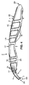
図1は、湿式の髭剃り剃刀1を示す。本発明は、剃刀の柄2及びシェービングカートリッジ3を備える。シェービングカートリッジ3は、好ましくは使い捨て式のシェービングカートリッジであり、1つ又は幾つかの刃3Aを備え、シェービングカートリッジ3は、図1及び2にそれぞれ示されるように、剃刀の柄2に接続する、又は剃刀の柄2から取り外すことができる。
FIG. 1 shows a
剃刀の柄2は、通常は湾曲した形状(横方向に見た)を有し、前端部2Aと、後端部2Bとの間で長手方向Cに延び、後端部2Bは前端部2Aに対向している。剃刀の柄2は、手が剃刀の柄2を把持するための細長い本体4をもまた有する。より詳細には、細長い本体4は後端部2Bから前端部2Aの近くの位置まで長手方向に延びる。剃刀は、前端部2Aまでの細長い本体4の延長に接続手段5をさらに備える。言い換えると、細長い本体4は、後端部2Bから接続手段5の始まりまで長手方向に延びる。シェービング剃刀1は、後端部2Bから接続手段5の自由端まで長手方向に延びる(自由端は、シェービングカートリッジ3に接続される端部)。
The razor handle 2 usually has a curved shape (seen in the lateral direction), extends in the longitudinal direction C between the
図3A及び3Bを参照すると、剃刀の柄2は中央面P1に対して対称であって良く、長手方向Cにおいて長さLを有することを見て取ることができ、長さLは100mm〜150mm、好ましくは約125mmである。細長い本体4の長さL4は約100mm〜約120mmであり、接続手段5の長さL5は約15〜25mmである。
Referring to FIGS. 3A and 3B, it can be seen that the razor handle 2 can be symmetric with respect to the central plane P1 and has a length L in the longitudinal direction C, the length L being between 100 mm and 150 mm, preferably Is about 125 mm. The length L 4 of the
好ましい実施形態では、剃刀の柄2の長さLは約126mmである。接続手段5の長さL5は約17mmである。細長い本体4の長さL4は約108mmである。
In a preferred embodiment, the length L of the razor handle 2 is about 126 mm. The length L 5 of the connecting
また、剃刀の柄2は、剃刀の柄2の長さLに沿って変化する高さH及び幅Wを規定することができる。剃刀の柄2の高さHは、方向Cに沿って変化することができるが、好ましくは15mm〜25mmであり、好ましくは約20mmである。図4に示すように、細長い本体4の最も小さい高さH1は、剃刀の柄2の略中心に位置する。
Also, the razor handle 2 can define a height H and a width W that vary along the length L of the
また、剃刀の柄2が前端部2Aの近傍に、最大とされた幅W1を有する第1の大きくされた部分Ep1を有することは、図3A及び図3Bの剃刀の柄2の上面図及び下面図に見ることができる。細長い本体はまた、剃刀の柄2の後端部2Bの近傍に位置する、最大とされた幅W2を有する第2の大きくされた部分Ep2を備える。第1及び第2の大きくされた部分Ep1、Ep2は、剃刀の柄2の略中心に位置する細い部分Spによってともに接続されている。特に、細い部分Spは、最小とされた幅W3を有する。第1の大きくされた部分Ep1は、この細い部分Spから接続手段5まで延び、第2の大きくされた部分Ep2は、後端部2Bからこの細い部分Spまで延びる。第1及び第2の大きくされた部分Ep1、Ep2は、長手方向Cに沿った長さLEp1、LEp2を有し、これら長さはそれぞれ、第1及び第2の大きくされた部分Ep1、Ep2間の、細い部分Spを有する接続部が滑らかな湾曲を有するように選択されている。
Further, the fact that the razor handle 2 has the first enlarged portion Ep1 having the maximum width W1 in the vicinity of the
好ましい実施形態では、第1の大きくされた部分Ep1の長さLEp1は約25mmである。第2の大きくされた部分Ep2の長さLEp2は約50mmである。細い部分Spの長さLSpは約25mmである。 In a preferred embodiment, the length L Ep1 of the first enlarged portion Ep1 is about 25 mm. The length L Ep2 of the second enlarged portion Ep2 is about 50 mm. The length L Sp thin portion Sp is about 25 mm.
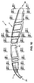
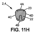
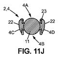
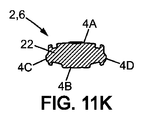
すべてが図10に示したような剃刀の柄に沿った断面図である図11A〜11Kに示すように、剃刀の柄2は断面で、剃刀の柄2の中央の近くに位置するゾーンを除いて滑らかなコーナーを有する一般的な台形状の形状を有する。この特定のゾーンでは、断面における剃刀の柄2の一般的な形状は、図11Hに示すように、より三角形状である。 11A-11K, all of which are cross-sectional views along the razor handle as shown in FIG. 10, the razor handle 2 is in cross section, except for the zone located near the center of the razor handle 2 It has a general trapezoidal shape with smooth corners. In this particular zone, the general shape of the razor handle 2 in cross section is more triangular, as shown in FIG. 11H.
この一般的な台形状の形状は、例えば図11D、11E、及び11Iに示されている仮想の台形TZによって、図に強調されている。台形状の形状は、指を置くための4つの異なる面を有し、一方で三角形状は3つの異なる面しか有さない。また、その一般的な台形状の形状の故に、剃刀の柄2はこのように、指による把持のためのより良い、大きな領域を有する。この特定の台形状の形状はしたがって、快適な把持及び髭剃りを容易にする。 This general trapezoidal shape is highlighted in the figure, for example by the virtual trapezoid TZ shown in FIGS. 11D, 11E, and 11I. The trapezoidal shape has four different surfaces for placing a finger, while the triangular shape has only three different surfaces. Also, because of its general trapezoidal shape, the razor handle 2 thus has a better, larger area for gripping with a finger. This particular trapezoidal shape therefore facilitates comfortable gripping and shaving.
図11A〜11Iには、前端部2Aの近傍(すなわち、そこでは接続手段5が手による把持を容易にするために設計された凹部を有する)及び後端部2Bにおける下面4Bを除いて、上面4Aと下面4Bとが凸面であることをさらに見て取ることができる。
11A-11I show the top surface except for the vicinity of the
接続手段5は細長い本体4と一体であり、細長い本体4から延びるとともに剃刀の柄2の前端部2Aにおける自由端6Bに向かって突出する2つの柔軟なアーム6を備える。言い換えると、柔軟なアーム6と細長い本体4とは一体である。
The connecting means 5 is integral with the
図9に示されるように、2つのアーム6は、V字状に配置することができ、剃刀の柄2の長手方向Cから分岐し、それぞれには自由端6Bにおいてシェービングカートリッジ3への接続のための支持構造7が設けられている。開示されている実施形態において、シェービングカートリッジ3は枢動タイプ(pivotal type)であり、支持構造7は、剃刀の柄2に接続されるときにシェービングカートリッジ3の枢動を可能とし、一方でアーム6間に延びるとともにシェービングカートリッジ上に形成された溝8Aと協働する長手方向の柔軟な舌部8が、シェービングカートリッジ3を図1に図示されているような静止位置に向かって付勢するばね力を提供する。しかし、シェービングカートリッジ3はまた、剃刀の柄2に対して固定することもできる。
As shown in FIG. 9, the two
それぞれのアーム6は、その上面に複数の小さな空洞21をさらに有する。そのような構造は、剃刀の柄2のこの部分の重量及びコストを節約しながら、人間の髭剃りの目的のための接続手段5に十分な構造的強度を提供する。より詳細には、アーム6及び柔軟な舌部8は滑らかなコーナーを有する四角形状の形状を有して、接続手段5の改善されたロバスト性を可能にしている。
Each
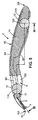
細長い本体4は外表面4E、より詳細には図3A及び3Bに示されているような上面4A及び下面4Bを有し、下面4Bは上面4Aに対向している。細長い本体4は、上面4Aと下面4Bとの間に備えられているとともに互いに対して対向し、また長手方向Cに延びる2つの側面4C、4Dをさらに有する。
The
細長い本体4及び接続手段5は、第1の材料22から成形された一体要素を形成する。
第1の材料22は、いずれの成形可能な材料であって良い。好ましくは、第1の材料22はプラスティック及びゴムの中から選択される。例えば、細長い本体4及び接続手段5は、熱可塑性材料、例えばアクリルニトリルブタジエンスチレン(ABS)又はポリプロピレン(PP)から成形することができる。
The
The
細長い本体4は、第1の孔部9及び第2の孔部10をさらに含む。第1の孔部9及び第2の孔部10は剃刀の柄2の第1の大きくされた部分Ep1及び第2の大きくされた部分Ep2の中にそれぞれ配置される。
The
第1の孔部9及び第2の孔部10は好ましくは貫通孔であり、この貫通孔は細長い本体4の上面4Aと下面4Bとの間に延びる。しかし、第1の孔部9及び第2の孔部10は細長い本体4の外表面4Eに、特に上面4A又は下面4Bに開口する、めくら孔とすることもまたできる。
The
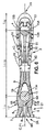
図7及び図8に示されるように、第1の孔部9及び第2の孔部10はそれぞれ内側壁9A、10Aを有し、これら内部側壁9A、10Aのそれぞれは、上面4A及び下面4Bの間で、細長い本体4の内側に備えられた内部空間9B、10Bを仕切っている。より詳細には、第1の孔部9及び第2の孔部10のそれぞれの内側壁9A、10Aは、半円状部分9C、10Cを備え、剃刀の柄2の中心の細い部分Spに向かってこれら半円状部分9C、10Cから長手方向CにV字状に合流している。また、第1の孔部9及び第2の孔部10は、図3A及び図3Bに示されるように上から又は下から見るときに、それぞれ逆方向に向いた滴状の形状を好ましくは有する。言い換えると、上から又は下から見ると、細い部分Spを介して接続された2つの孔部はある種の8の字を形成する一般的な形状を有する。
As shown in FIGS. 7 and 8, the
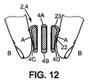
剃刀の柄2の指による把持を断面図に示す図12に示されるように、使用者の指が細長い本体4の側面4C、4D(点A)に置かれるとき、空気圧は第1及び第2の孔部9、10と、剃刀の柄2の周り(点B)とで同じである。しかし、図13に示すように、使用者が指を、細長い本体4の上面及び下面4A、4B上に置くときには、指の表面は孔部の形状、例えば第2の孔部10の形状にしたがう。
When the user's finger is placed on the
第1の孔部9の長手方向に沿った長さL9は、10mm〜30mm、好ましくは約20mmである。第2の孔部の長手方向に沿った長さL10は、30mm〜50mm、好ましくは約40mmである。また、図3Bに示すように、第1の大きくされた部分Ep1は、接続手段5から剃刀の柄2の中心に向かって配置された第1の孔部9の端部へ延びている。細い部分Spは、剃刀の柄2の中心に向かって配置された第1の孔部9のこの端部から、これもまた剃刀の柄2の中心に向かって配置された第2の孔部10の端部へ延びている。第2の大きくされた部分Ep2は、剃刀の柄2の中心に向かって配置された第2の孔部10の端部から後端部2Bへ延びている。
First length L 9 along the longitudinal direction of the
剃刀の柄2は、第1の孔部9及び第2の孔部10それぞれの内部空間9B、10B内のそれぞれに配置された第1のインサート11及び第2のインサート12をさらに備える。より詳細には、第1のインサート11及び第2のインサート12は、図5に示されているように第1の孔部9及び第2の孔部10内それぞれに部分的に封止されている。さらに、第1のインサート11及び第2のインサート12の表面は、直接的に又は間接的に、後述されるように使用者の指に接触可能とすることができる。さらに、第1のインサート11及び第2のインサート12のそれぞれの表面は、細長い本体4の上面4A及び/又は下面4B上のフィンガーレスト領域を形成する。好ましくは、第1のインサート11及び第2のインサート12の表面の75%未満、好ましくは50%未満は、第1の孔部9及び第2の孔部10内に封止されている。言い換えると、封止されている第1のインサート11及び第2のインサート12の表面は、細長い本体4の第1の材料22で取り囲まれているので、使用者によって直接的に接触されることはできない。
The razor handle 2 further includes a
このように、使用者が髭剃りをしたいときには、その人は指を第1の孔部9及び第2の孔部10の場所、好ましくは封止されていない第1のインサート11及び第2のインサート12の表面上に置くことができる。好ましくは、第1のインサート11及び第2のインサート12は、剃刀の柄2が人差し指と親指との間に保持される位置のような所定の髭剃り位置において、親指は上面4Aの第1のインサート11上にあり、人差し指は剃刀の柄2の下面4Bの第1のインサート11上にあるように、手による把持を改良する。また別の髭剃り位置では、使用者の親指と人差し指はまた、第2のインサート12上にあってもよい。以下に詳細に述べるように、第2のインサート12は、リブ14が第2のインサート12を部分的に覆っている場合があるので、上面4A上の使用者の指で直接的に接触できない場合がある。したがって、使用者は、髭剃りの時に細長い本体4の上面4Aのリブ14上に指を位置させることができる。しかし、前記リブ14によって覆われてはいるが、第2のインサート12は、リブ14を支持するので、フィンガーレスト領域を形成する。言い換えると、第2のインサート12は別の材料(すなわちリブ14の材料)によって少なくとも部分的に覆われるということになる。
Thus, when the user wishes to shave, the person places his finger in the location of the
第1のインサート11及び第2のインサート12は、好ましくは金属、プラスティック、及びゴムの中から選択された材料から成る。特に、第1のインサート11及び/又は第2のインサート12は、好ましくは細長い本体4の第1の材料22の密度とは大幅に異なる密度を有する剛体材料から成る。
The
例えば、第1のインサート11及び第2のインサート12の密度は、細長い本体4の第1の材料22の密度より大きくすることができる。したがって、第1のインサート11及び第2のインサート12は、柄2の体積を大幅に増加させることなく、剃刀の柄2の重量を大きくすることに貢献する。結果として、剃刀の柄2は良好な髭剃りを提供し、シェービングカートリッジ3の刃3Aと、剃られる使用者の皮膚と、の間に良好な接触がもたらされるのを確実とするのに十分重くすることができる。好ましくは、第1のインサート11及び第2のインサート12のそれぞれは、金属のみからなり、他の材料を含まない。
For example, the density of the
また、第1のインサート11及び/又は第2のインサート12に対して選択された材料は、使用者がその指を第1のインサート11及び第2のインサート12上に位置させるときに、使用者の検知経験に影響を与える場合がある。例として、金属から成るインサートは使用者の指とピンポイントの接触を提供し、したがって髭剃りからのすべての伝達される振動の情報を可能にする。逆に、熱可塑性材料のようなゴムから成るインサートは髭剃りからのほとんどの振動を吸収し、それら振動を使用者の指に伝達することはない。
Also, the material selected for the
代替例として、第1のインサート11及び第2のインサート12は、両方が必ずしも同じ材料でなくてもよい。例えば、第1の孔部9内に設けられた第1のインサート11は金属から成ることができ、第2の孔部10内に設けられた第2のインサート12はゴムから成ってもよく、又はその逆であってもよい。
As an alternative, both the
また別の代替形として、第1のインサート11を金属から成る球体とし、第2のインサート12をゴムから成る球体とすることができる。この最後の代替形によれば、第1のインサート11は、このように金属から成り、使用者がその人差し指をその上に置くときに快適な感覚と柄のコントロールとを強化する。それはまた、金属から成る第1のインサートと、細長い本体4の第1の材料22との間に存在する質感、温度、及び形状の差によって、使用者の方向性のある触覚のフィードバックを向上させる。第2のインサート12は、したがって剃刀の柄2上に指を置いたときに、柔らかさを高める球体である。それはまた、第1のインサート11が金属製球体であるこの特定の代替形における第1のインサートの視覚的継続性を向上させる。
As another alternative, the
さらに、第1のインサート11及び第2のインサート12のそれぞれはまた、いくつかの材料で作ることもできる。特に、第1のインサート11及び第2のインサート12は、滑らかな表面を有する別の材料の層で覆うことができる。例としては、第1のインサート11及び第2のインサート12は金属から作られ、ゴムの層で覆われてもよい。この実施形態では、層は0.5μm〜1.6μm(粗さRa)を備える表面仕上げを有することができる。
Furthermore, each of the
第1のインサート11及び第2のインサート12はまた、でこぼこな表面、例えば刻み付きパターン(knurled pattern)又はディボットパターン(divot pattern)によるクレーター又はバンプを有してもよい。実際のところ、第1のインサート11及び第2のインサート12の表面のタイプは、使用者がその指を第1のインサート11及び第2のインサート12に位置付けるときに、使用者の触知性に影響する。
The
また別の代替例として、第1のインサート11及び/又は第2のインサート12は、一方の半球がゴムから成り、他方の半球がプラスティックから成る球体とすることができる。このように、第1のインサート11及び第2のインサート12は、異なるタイプのフィンガーレスト領域を提供することによって2つの目的を果たすことができる。
As another alternative, the
したがって、第1のインサート11及び第2のインサート12によって、細長い本体4は、既知の剃刀の柄に使用される材料に比べたときに、軽く、安い材料から作ることができる。それでもなお、第1の材料22の軽さにもかかわらず、第1のインサート11及び第2のインサート12のおかげで、剃刀の柄2は依然として良質な外観と、最適化された重量を有する。 さらに、剃刀の柄2の重量は、剃刀の柄2の前端分2A及び後端部2Bに限定されて(localized)選択され、したがって剃刀の柄2の良好なバランスを確実にしている。
Thus, the
第1のインサート11及び/又は第2のインサート12は、球状の形状を有することができる。第1のインサート11及び/又は第2のインサート12は、卵型状の形状を有することができる。より一般的には、インサートは、平行六面体、立方体、又は円柱状の形状のようないずれかの他の形状を有することができる。さらに、第1のインサート11及び第2のインサート12は、同じ形状を有することができ、又は異なる形状を有することができる。同様に、第1のインサート11及び第2のインサート12は、同じ寸法を有することも、異なる寸法を有することもできる。さらに、第1のインサート11及び第2のインサート12は、同じ材料を含むことも、異なる材料を含むこともできる。
The
好ましくは、第1のインサート11及び第2のインサート12の包含(inclusion)は、細長い本体4の形状の過剰な変形をもたらすことはない。さらに、細長い本体4の形状は、インサートを含まない細長い本体の形状と同様に維持される。図1〜3及び5〜8に示すように、第1のインサート11及び第2のインサート12のそれぞれは、好ましくは単一の球である。しかし、第1のインサート11及び第2のインサート12は、完全な球体でなくてもよく、部分的な曲面、特にフィンガーレスト領域を提供する部分的な球面を単に備えてもよい。
Preferably, the inclusion of the
さらに、第1のインサート11及び第2のインサート12は、第1の孔部9及び第2の孔部10それぞれの内部空間9B、10Bよりそれぞれ小さい(inferior)サイズを有する。また、図4A及び図3Bに示されているように、長手方向Cの第1の孔部及び第2の孔部の長さL9、L10は、第1のインサート11及び第2のインサート12の長手方向の大きさより大きい。より具体的には、インサートが図に示すように球体である特定の実施形態において、そのような球体は、10mm〜20mm、好ましくは15mm未満、より好ましくは約12mmの直径Dを有する。
Further, the
一実施形態では、第1のインサート11及び第2のインサート12は好ましくは、第1の孔部9及び第2の孔部10内にそれぞれ保持され、有利には固定されており、したがって、使用者が第1の孔部9及び第2の孔部10から取り外すことはできない。さらに、第1のインサート11及び第2のインサート12は、第1の孔部9及び第2の孔部10中でいずれの態様でも動くことができない。その結果として、第1のインサート11及び第2のインサート12は、第1の孔部9及び第2の孔部10に対してそれぞれ動くことができない(すなわち動かせない又は静止している)。動かない第1のインサート11及び第2のインサート12はしたがって、フィンガーレスト領域を形成する。より正確には、第1のインサート11及び第2のインサート12はそれらの対応する第1の孔部9及び第2の孔部10の中で滑動できない。
In one embodiment, the
より具体的には、図7に示すように、保持リング13が剃刀の柄2の対象面P1に垂直な平面P2において第1の孔部9の内側壁9Aから突出し、前記第1のインサート11を前記第1の孔部9内に維持するために第1のインサート11を部分的に周状に取り囲む。
More specifically, as shown in FIG. 7, the holding
しかし、また別の実施形態では、第1のインサート11及び/又は第2のインサート12は、それ自身の軸の回りにそれ自体ですべての方向に回転することができる球体とすることができる。また、第1のインサート11と、保持リング13と、の間に隙間を設けることができ、それによって、第1のインサート11が球体であるときに、第1のインサート11の回転を容易にしている。この隙間は、第1のインサート11の選択された回転の自由度に応じて、0.005μm〜0.025μmとすることができる。隙間が小さいほど、第1のインサート11が容易に回転しないようにし、隙間が大きいほど、回転を容易にする。第1のインサート11及び/又は第2のインサート12、並びに/或いは第1の孔部9及び/又は第2の孔部10の表面仕上げが、この可動性、特に回転を可能にするように適用される。
However, in yet another embodiment, the
したがって、その場合には、第1のインサート11及び/又は第2のインサート12のうちの一方が動かないようにすることができる。
Therefore, in that case, one of the
また別の実施形態では、第1のインサート11及び第2のインサート12の両方が可動である。第1のインサート11及び第2のインサート12は、例えば可動である、特にそれらの対応する第1の孔部9及び第2の孔部10内で、それら自身の周りに滑動する球体とすることができる。
In yet another embodiment, both the
第1のインサート11及び/又は第2のインサート12が異なる材料から成り、したがって異なる密度を有する2つの半球を備える場合には、使用者は第1のインサート11と第2のインサート12とを回転させることによって必要に応じて2つの半球間で切り替えることができる。
If the
そのような可動な第1のインサート11及び/又は第2のインサート12上に指のうちの1つを置くことができる使用者は、その指を第1のインサート11及び/又は第2のインサート12上で絶えず滑らしながら髭剃りをすることが難しいことがわかるだろう。したがって、髭剃りは不正確で心地よくない。
A user who can place one of his fingers on such a movable
結果として、第1のインサート11又は第2のインサート12が対応する第1の孔部9又は第2の孔部10に対してそれぞれ可動であるときには、第1のインサート11又は第2のインサート12はフィンガーレスト領域を形成できない。より正確には、第1のインサート11が可動であるときには、第1のインサート11はフィンガーレスト領域ではあり得ない。
As a result, when the
図8に示すように、第2の孔部10は、長手方向Cに、第2の孔部10の中において平面P1内で延びる細長いバー14によって2つの部分に分割されている。細長いバー14は、第2の孔部10内に第2のインサート12を維持するための、第2のインサート12を周状に部分的に取り囲む部分14Aを備える。第2の孔部10の内側壁10Aは、互いに対向するとともに内側壁10Aから突出し、かつ第2の孔部10内に第2のインサート12を維持するための、第2のインサート12の形状に部分的に補完的である形状を有する2つの小さな突起15A、15Bをもまた備える。しかし、第1のインサート11に関して上述したように、隙間もまた、第2のインサート12と、部分14Aとの間に設けることができ、それによってこの第2のインサート12が球体である場合には、第2のインサート12の回転を容易にする。
As shown in FIG. 8, the
第1の孔部9及び第2の孔部10の中にそれぞれ維持することによって、第1のインサート11及び第2のインサート12はそれぞれ剃刀の柄2の前端部2A及び後端部2Bに配置される。好ましくは、第1のインサート11は、前端部2Aから約25mmの長手方向(C)に沿って測定された距離L11に配置された第1の点11A上に重心を置いている。第2のインサート12は後端部1Bの近傍に配置される。好ましくは、第2のインサート12は、後端部2Bから約25mmの長手方向Cに沿って測定された距離L12に配置された第2の点12A上に重心を置いている。
By maintaining in the
図5に示すように、第1のインサート11及び第2のインサート12が球体である特定の実施形態では、第1の点11A及び第2の点12Aそれぞれは、前記第1のインサート11及び第2のインサート12の中心に対応する。
As shown in FIG. 5, in a specific embodiment in which the
長手方向(C)に沿って測定された第1の点11Aと第2の点12Aとの間の距離L11−12は、好ましくは60mm〜100mm、好ましくは約78mmである。しかし、この距離L11−12は、細長い本体4の長さL4並びに第1のインサート及び第2のインサート12による望ましい重量バランスに依存して変化する場合がある。
The distance L 11-12 between the
特に、インサートの無い既知の剃刀は通常、剃刀の柄の中心、又は剃刀の柄の方に前端部にわずかに向かって位置するバランスの中心を有する。このために、剃刀の柄の後端部はその前端部よりも大幅に大きくすることはできず、逆もまたできず、それによってこのバランスの中心を達成している。本発明では、剃刀の柄2の前端部2A及び後端部2Bから正確な距離に第1のインサート11及び第2のインサート12を加えることによって、剃刀の柄2の形状に関係なくこのバランスの中心の位置を制御することが可能である。例えば、第2の大きくされた部分Ep2が第1の大きくされた部分Ep1よりも大幅に大きいとしても、バランスの中心を長手方向(C)における剃刀の柄2の中心に置くことができる。
In particular, known razors without inserts usually have a razor handle center or a balance center located slightly towards the front end towards the razor handle. For this reason, the rear end of the razor handle cannot be made significantly larger than its front end, and vice versa, thereby achieving this center of balance. In the present invention, by adding the
細長い本体4は、いくつかの異なる材料を備えることができる。例えば、細長い本体4はまた、第1の材料22とは異なる、好ましくはプラスティック及びゴムの中から選択された第2の材料23の層を備えることができる。第1の材料22は剃刀の柄2に構造的な強度を提供し、一方で第2の材料は23快適な手での把持と、いずれのシェービング位置においても確かな指でのグリップのために必要とされる柔らかさと、を提供する。
The
図3A及び3Bに示すように、上面4Aの少なくとも一部分19及び下面4Bの少なくとも一部分20、並びにこれら面4A、4Bの大部分は第2の材料で覆うことができ、それによって前記部分19、20それぞれは上側把持領域及び下側把持領域を形成する。
As shown in FIGS. 3A and 3B, at least a
例えば図11A〜11Kに見ることができるように、第2の材料23は、細長い本体4の上面4Aの大部分、好ましくはすべてを覆う。また、第2の材料23も、細長い本体4の下面4Aの大部分、好ましくはすべてを覆う。
For example, as can be seen in FIGS. 11A-11K, the
図7に示すように、第2の材料23もまた少なくとも部分的に第1の孔部9の内側壁9B上を、第1のインサート11を維持する保持リング13を覆うことなく、オーバーフローすることができる。
As shown in FIG. 7, the
細長い本体4の側面4C、4Dは、第2の材料から成る複数の滑らかなリブ16をさらに備える。図4に示すように、細長い本体4の側面4C、4Dそれぞれは、好ましくは上側把持領域19及び下側把持領域20をともに接続する複数のリブ16を備える。図4に示す特定の実施形態では、第1の大きくされた部分Ep1の側面4C、4Dは2つのリブ16を備え、第2の大きくされた部分Ep2の側面4C、4Dは4つのリブ16を備える。
The side surfaces 4C and 4D of the
図1〜4及び9に示すように、側面4C、4Dのそれぞれもまた、接続手段5と一体であるとともに接続手段5の細長い本体4との結合点において剃刀の柄2の前端部2Aの近傍に配置された複数の離間した突出するピン18を備える、側部把持領域17を備える。側部把持領域17は、特に親指と人差し指とが前端部2A及び好ましくは正確な髭剃りの必要性を満足させるためのアーム6の非常に近くに位置するシェービング位置における、剃刀の柄2の指による把持を強化する。
1-4 and 9, each of the side surfaces 4C, 4D is also integral with the connecting
本発明によれば、(第1及び/又は第2の)インサートを、その対応する孔部内において可動若しくは不動にすることができ、さらに、(第1及び/又は第2の)インサートを、球状又はインサートの可動性を可能にする他のいずれかの形状にすることができる。
(第1及び/又は第2の)インサート及び/又は(第1及び/又は第2の)孔部の材料及び/又は表面仕上げは、この可動性、特に回転による可動性を可能にするように適用される。さらに、(第1及び/又は第2の)インサートはたとえ可動である場合であっても、対応する孔部に挿入されている場合には柄から取り外し可能ではない。
According to the invention, the (first and / or second) insert can be made movable or immobile in its corresponding hole, and the (first and / or second) insert can be spherical. Or any other shape that allows the mobility of the insert.
The material and / or surface finish of the (first and / or second) insert and / or the (first and / or second) hole so as to enable this mobility, in particular mobility by rotation. Applied. Furthermore, even if the (first and / or second) insert is movable, it is not removable from the handle when inserted into the corresponding hole.
C 長手方向
2 剃刀の柄
2A 前端部
2B 後端部
3 シェービングカートリッジ
4 細長い本体
4A 上面
4B 下面
4C、4D 側面
4E 外表面
5 接続手段
9 第1の孔部
9A 内側壁
9B、10B 内部空間
10 第2の孔部
10A 内側壁
11 第1のインサート
11A 第1の点
12 第2のインサート
12A 第2の点
13 保持リング
14 細長いバー
14A 取り囲む部分
15A、15B 突起
16 リブ
18 ピン
19 上側把持領域
20 下側把持領域
22 第1の材料
23 第2の材料
C
Claims (26)
前記細長い本体(4)は外表面(4E)を有するとともに第1の孔部(9)と、第2の孔部(10)と、を設けられ、前記第1及び第2の孔部(9、10)は前記細長い本体(4)の前記外表面(4E)に開口し、前記剃刀の柄(2)は第1のインサート(11)及び第2のインサート(12)をさらに備える、剃刀の柄(2)において、
前記第1及び第2のインサート(11、12)は、前記第1及び第2の孔部(9、10)内にそれぞれ部分的に封止されていることを特徴とする剃刀の柄(2)。 A razor handle (2) comprising an elongated body (4) extending in the longitudinal direction (C),
The elongated body (4) has an outer surface (4E) and is provided with a first hole (9) and a second hole (10), and the first and second holes (9). 10) opens into the outer surface (4E) of the elongate body (4) and the razor handle (2) further comprises a first insert (11) and a second insert (12). In handle (2),
The razor handle (2), wherein the first and second inserts (11, 12) are partially sealed in the first and second holes (9, 10), respectively. ).
前記細長い本体(4)は外表面(4E)を有するとともに第1の孔部(9)を設けられ、前記第1の孔部(9)は前記細長い本体(4)の前記外表面(4E)上に開口し、前記剃刀の柄(2)は第1のインサート(11)をさらに備え、前記第1のインサートは、前記第1の孔部(9)内に部分的に封止された球体であり、前記剃刀の柄(2)は、断面では、第1の孔部(9)の近傍に、滑らかなコーナーを有する一般的な台形状形状(TZ)を有することを特徴とする剃刀の柄(2)。 A razor handle (2) comprising an elongated body (4) extending in the longitudinal direction (C),
The elongated body (4) has an outer surface (4E) and is provided with a first hole (9), the first hole (9) being the outer surface (4E) of the elongated body (4). A sphere open to the top, wherein the razor handle (2) further comprises a first insert (11), the first insert being partially sealed in the first hole (9) The razor handle (2) has a general trapezoidal shape (TZ) having smooth corners in the vicinity of the first hole (9) in cross section. Handle (2).
Applications Claiming Priority (3)
| Application Number | Priority Date | Filing Date | Title |
|---|---|---|---|
| PCT/EP2014/054008 WO2015128000A1 (en) | 2014-02-28 | 2014-02-28 | A razor handle comprising inserts within holes and razor comprising such a razor handle |
| EPPCT/EP2014/054008 | 2014-02-28 | ||
| PCT/EP2014/064805 WO2015128009A1 (en) | 2014-02-28 | 2014-07-10 | A razor handle comprising inserts within holes and razor comprising such a razor handle |
Publications (2)
| Publication Number | Publication Date |
|---|---|
| JP2017506551A true JP2017506551A (en) | 2017-03-09 |
| JP6427593B2 JP6427593B2 (en) | 2018-11-21 |
Family
ID=50189713
Family Applications (2)
| Application Number | Title | Priority Date | Filing Date |
|---|---|---|---|
| JP2016554323A Pending JP2017510335A (en) | 2014-02-28 | 2014-02-28 | Razor handle with an insert in the hole and a razor with such a razor handle |
| JP2016554355A Active JP6427593B2 (en) | 2014-02-28 | 2014-07-10 | Razor handle with insert in the hole and razor with such razor handle |
Family Applications Before (1)
| Application Number | Title | Priority Date | Filing Date |
|---|---|---|---|
| JP2016554323A Pending JP2017510335A (en) | 2014-02-28 | 2014-02-28 | Razor handle with an insert in the hole and a razor with such a razor handle |
Country Status (11)
| Country | Link |
|---|---|
| US (5) | US10486321B2 (en) |
| EP (2) | EP3110599B1 (en) |
| JP (2) | JP2017510335A (en) |
| KR (2) | KR101947665B1 (en) |
| CN (2) | CN106061693B (en) |
| BR (2) | BR112016018991B1 (en) |
| CA (2) | CA2937701A1 (en) |
| MX (2) | MX2016010576A (en) |
| PL (2) | PL3110599T3 (en) |
| RU (2) | RU2652314C2 (en) |
| WO (2) | WO2015128000A1 (en) |
Cited By (1)
| Publication number | Priority date | Publication date | Assignee | Title |
|---|---|---|---|---|
| JP2017510335A (en) * | 2014-02-28 | 2017-04-13 | ビック・バイオレクス・エス・エー | Razor handle with an insert in the hole and a razor with such a razor handle |
Families Citing this family (36)
| Publication number | Priority date | Publication date | Assignee | Title |
|---|---|---|---|---|
| KR100749925B1 (en) * | 2006-06-29 | 2007-08-16 | 주식회사 도루코 | Razor |
| CN106573386B (en) * | 2014-08-04 | 2021-10-22 | 比克-维尔莱克 | Razor handle comprising an insert freely movable in an inner cavity and razor comprising such a razor handle |
| BR112017001286A2 (en) * | 2014-08-04 | 2018-01-30 | Bic Violex Sa | razor blade and razor blade |
| CA2984113C (en) * | 2015-02-01 | 2023-10-10 | Mack-Ray, Inc. | Dual sided razor |
| USD812815S1 (en) * | 2016-03-02 | 2018-03-13 | Societe Bic | Shaver handle |
| USD810537S1 (en) * | 2016-03-24 | 2018-02-20 | Home Depot Product Authority, Llc | Overstrike for a striking tool |
| US20170281476A1 (en) | 2016-04-01 | 2017-10-05 | The Procter & Gamble Company | Oral Care Compositions Containing A Gel Network Phase |
| EP3372358B1 (en) | 2017-03-10 | 2021-07-21 | The Gillette Company LLC | Razor handle |
| PL3592514T3 (en) * | 2017-03-10 | 2021-10-04 | Bic-Violex Sa | Shaver handle, shaver including such a handle and method of manufacturing the same |
| EP3388210B1 (en) * | 2017-04-13 | 2022-06-29 | BIC Violex Single Member S.A. | Razor handle |
| US20180297221A1 (en) * | 2017-04-18 | 2018-10-18 | The Gillette Company Llc | Shaving razor system and method of manufacture |
| CN107825475A (en) * | 2017-11-24 | 2018-03-23 | 陈家乐 | The cutter of motion state is experienced by shank end plane contact hand skin nerve |
| US11607820B2 (en) | 2018-03-30 | 2023-03-21 | The Gillette Company Llc | Razor handle with movable members |
| BR112020020132A2 (en) | 2018-03-30 | 2021-01-05 | The Gillette Company Llc | HANDLE OF SHAVING OR DEVILING APPLIANCE WITH MOBILE LIMBS |
| WO2019191178A1 (en) | 2018-03-30 | 2019-10-03 | The Gillette Company Llc | Razor handle with movable members |
| WO2019191163A1 (en) | 2018-03-30 | 2019-10-03 | The Gillette Company Llc | Razor handle with a pivoting portion |
| EP3774230A1 (en) | 2018-03-30 | 2021-02-17 | The Gillette Company LLC | Razor handle with a pivoting portion |
| WO2019191345A1 (en) | 2018-03-30 | 2019-10-03 | The Gillette Company Llc | Razor handle with a pivoting portion |
| EP3546156B1 (en) | 2018-03-30 | 2021-03-10 | The Gillette Company LLC | Razor handle with a pivoting portion |
| JP2021516102A (en) | 2018-03-30 | 2021-07-01 | ザ ジレット カンパニー リミテッド ライアビリティ カンパニーThe Gillette Company Llc | Razor handle with pivot part |
| USD874061S1 (en) | 2018-03-30 | 2020-01-28 | The Gillette Company Llc | Shaving razor cartridge |
| BR112020020117A2 (en) | 2018-03-30 | 2021-01-26 | The Gillette Company Llc | shaving or shaving cartridge |
| US11345055B2 (en) | 2018-09-05 | 2022-05-31 | The Gillette Company Llc | Razor cartridge structure |
| US11298842B2 (en) * | 2018-09-05 | 2022-04-12 | The Gillette Company Llc | Razor structure |
| EP3659463B1 (en) | 2018-11-29 | 2021-09-01 | Bic Violex S.A. | Bladeless exfoliation head, handheld skincare device and shaving kit |
| EP3666479B1 (en) * | 2018-12-14 | 2024-01-24 | BIC Violex Single Member S.A. | Blade assembly attachment mechanism and modular razor assembly |
| US11235484B2 (en) * | 2019-01-20 | 2022-02-01 | iP TECH PROS Inc. | Safety razor and utility case system and method of use thereof |
| EP3744490B1 (en) * | 2019-05-29 | 2022-11-09 | BIC Violex Single Member S.A. | Handle assembly and recycling process therefor |
| US11800924B2 (en) * | 2019-12-03 | 2023-10-31 | Colgate-Palmolive Company | Oral care implement |
| US11350729B2 (en) | 2019-12-03 | 2022-06-07 | Colgate-Palmolive Company | Oral care implement |
| USD971608S1 (en) | 2019-12-03 | 2022-12-06 | Colgate-Palmolive Company | Toothbrush |
| CN111558957B (en) * | 2020-06-18 | 2022-04-26 | 广州威的科技有限公司 | Razor head and razor |
| US11413776B2 (en) * | 2020-12-09 | 2022-08-16 | The Gillette Company Llc | Shaving razor system |
| US20220227014A1 (en) * | 2021-01-21 | 2022-07-21 | Rk Inventions, Llc | Razor with intermittent encapsulation of embedded blades |
| US20220379509A1 (en) * | 2021-05-25 | 2022-12-01 | The Gillette Company Llc | Integrated spring element |
| CN216658034U (en) * | 2021-11-03 | 2022-06-03 | 深圳诺泰科电子有限公司 | Shaver |
Citations (6)
| Publication number | Priority date | Publication date | Assignee | Title |
|---|---|---|---|---|
| JP2001513006A (en) * | 1997-02-19 | 2001-08-28 | ザ、ジレット、カンパニー | Shaving razor and method of manufacturing shaving razor handle |
| US20030070309A1 (en) * | 2001-10-15 | 2003-04-17 | Brown William R. | Handles for personal care products |
| JP2003311048A (en) * | 2002-04-25 | 2003-11-05 | Kaijirushi Hamono Kaihatsu Center:Kk | Razor handle and method of manufacturing the same |
| WO2006081842A1 (en) * | 2005-02-03 | 2006-08-10 | Bic Violex Sa | Razor handle having ergonomic gripping areas |
| US20090158540A1 (en) * | 2005-09-16 | 2009-06-25 | Trisa Holding Ag | Handle for a Brush, In Particular a Toothbrush |
| JP2017510335A (en) * | 2014-02-28 | 2017-04-13 | ビック・バイオレクス・エス・エー | Razor handle with an insert in the hole and a razor with such a razor handle |
Family Cites Families (56)
| Publication number | Priority date | Publication date | Assignee | Title |
|---|---|---|---|---|
| US2189689A (en) * | 1937-04-03 | 1940-02-06 | Ralph E Thompson | Safety razor |
| US4028803A (en) * | 1976-07-06 | 1977-06-14 | Currie Philip V | Locking mechanism |
| US4721021A (en) * | 1986-09-10 | 1988-01-26 | Kusznir Phillip S | Handle structure |
| DE8911280U1 (en) * | 1989-09-22 | 1991-01-24 | Wilkinson Sword Gmbh, 5650 Solingen, De | |
| USD355049S (en) * | 1991-02-04 | 1995-01-31 | Warner-Lambert Company | Razor handle |
| US5129157A (en) * | 1991-07-26 | 1992-07-14 | Barry Wood | Sphere shaver |
| US5361766A (en) * | 1993-02-17 | 1994-11-08 | David Nichols | Quick release bone probe and x-ray marker |
| US5497551A (en) * | 1994-10-13 | 1996-03-12 | The Gillette Company | Razor handle assembly |
| US5787586A (en) * | 1996-04-10 | 1998-08-04 | The Gillette Company | Shaving system and method |
| JP3195243B2 (en) | 1996-08-06 | 2001-08-06 | フェザー安全剃刀株式会社 | Shaving sword |
| US5915847A (en) * | 1998-02-25 | 1999-06-29 | Spears; Cecil J. | Drain stopper with lift mechanism |
| US6308416B1 (en) * | 1998-12-31 | 2001-10-30 | The Gillette Company | Surface conforming shaving razor and handle therefor |
| US6105255A (en) * | 1999-03-05 | 2000-08-22 | Kantas Products Co., Ltd. | Folding knife |
| US7086160B2 (en) * | 2002-10-21 | 2006-08-08 | Eveready Battery Company, Inc. | Bidirectional shaving implement |
| US20040216311A1 (en) | 2003-03-28 | 2004-11-04 | Eveready Battery Company, Inc. | Razor handle assembly |
| US20050039338A1 (en) * | 2003-07-07 | 2005-02-24 | Eveready Battery Company, Inc. | Pivotable shaving cartridge and razor including same |
| US6915576B2 (en) * | 2003-08-12 | 2005-07-12 | Lisa M. Brzezinski | Illuminated safety razor |
| DE20314274U1 (en) * | 2003-09-12 | 2004-05-27 | Faber-Castell Ag | Wood-framed pen for writing, painting, drawing and cosmetic purposes |
| GB0326646D0 (en) * | 2003-11-14 | 2003-12-17 | Gillette Co | Safety razors |
| USD511223S1 (en) * | 2003-12-02 | 2005-11-01 | Kai R & D Center Co., Ltd. | Holder for a safety razor |
| US7168173B2 (en) * | 2004-03-11 | 2007-01-30 | The Gillette Company | Shaving system |
| GB0415871D0 (en) * | 2004-07-15 | 2004-08-18 | Glaxosmithkline Consumer Healt | Toothbrush |
| US7334286B2 (en) * | 2004-08-18 | 2008-02-26 | Loops, Llc | Toothbrush and methods of making and using same |
| BRPI0519868A2 (en) | 2005-02-03 | 2009-09-15 | Bic Violex Sa | shaver cord, safety razor |
| CA2596785A1 (en) * | 2005-02-03 | 2006-08-10 | Bic-Violex Sa | Razor handle having converging side surfaces |
| EP1848572A1 (en) * | 2005-02-03 | 2007-10-31 | BIC Violex S.A. | Razor handle having a reticulated head portion |
| BRPI0519867B1 (en) * | 2005-02-03 | 2019-03-19 | Bic-Violex Sa | Shaving Cord |
| US7409767B2 (en) * | 2005-04-05 | 2008-08-12 | Eveready Battery Company, Inc. | Razor handle |
| USD533964S1 (en) * | 2005-05-05 | 2006-12-19 | The Gillette Company | Razor handle |
| AU2006262338B2 (en) * | 2005-06-20 | 2012-06-07 | Edgewell Personal Care Brands, Llc | Shaving implement having a cap forward pivot |
| CN101213054A (en) * | 2005-06-28 | 2008-07-02 | 比克-维奥利克斯公司 | Razor handle with improved grip capability |
| US20070050996A1 (en) * | 2005-09-06 | 2007-03-08 | Fred Schnak | Razors |
| USD542471S1 (en) * | 2006-01-25 | 2007-05-08 | Eveready Battery Company, Inc. | One-piece razor handle |
| US7461458B2 (en) * | 2006-06-14 | 2008-12-09 | Eveready Battery Company, Inc. | Wet shaving razor |
| US7779543B2 (en) * | 2006-09-28 | 2010-08-24 | Eveready Battery Company, Inc. | Razor with moveable center of balance |
| US8186062B2 (en) * | 2007-03-19 | 2012-05-29 | Eveready Battery Company, Inc. | Safety razor with filament guard |
| KR100903191B1 (en) * | 2007-05-31 | 2009-06-17 | 주식회사 도루코 | Shaver |
| USD587846S1 (en) * | 2007-11-28 | 2009-03-03 | American Safety Razor | Razor handle |
| US20090158600A1 (en) * | 2007-12-20 | 2009-06-25 | Alon Ben Ishai | Kitchen implement with weight-adjustable handle |
| US20100005669A1 (en) * | 2008-07-14 | 2010-01-14 | Florina Winter | Razor Handle |
| US20100064521A1 (en) * | 2008-09-10 | 2010-03-18 | Delong Douglas | Razor with cleaning brush |
| US8151468B2 (en) * | 2008-09-26 | 2012-04-10 | The Gillette Company | Handle for shaving razors having improved grip |
| US20100263219A1 (en) * | 2008-12-17 | 2010-10-21 | Kempker Jeffrey A | Tool with ergonomic handle and replaceable cutter head |
| US10093052B2 (en) * | 2009-05-27 | 2018-10-09 | Bic Violex S.A. | Molded product incorporating a label, and razor handle comprising such a molded product |
| CA2763243C (en) * | 2009-05-28 | 2016-10-25 | Koninklijke Philips Electronics N.V. | Pivoting arrangement |
| USD635716S1 (en) * | 2010-04-06 | 2011-04-05 | Eveready Battery Company, Inc. | Safety razor |
| USD636938S1 (en) * | 2010-05-12 | 2011-04-26 | American Safety Razor | Razor handle |
| JP5860707B2 (en) * | 2011-05-18 | 2016-02-16 | 株式会社貝印刃物開発センター | Swing razor |
| JP6093551B2 (en) * | 2012-11-06 | 2017-03-08 | 株式会社貝印刃物開発センター | razor |
| US9643327B2 (en) * | 2013-02-20 | 2017-05-09 | The Gillette Company | Wet shaving razor |
| US20140230256A1 (en) * | 2013-02-20 | 2014-08-21 | The Gillette Company | Hand held device |
| US20140230258A1 (en) * | 2013-02-20 | 2014-08-21 | The Gillette Company | Compact hand held device |
| US9873206B2 (en) * | 2014-03-13 | 2018-01-23 | Karl O. Gulledge | Interchangeable shaver |
| WO2016020009A1 (en) * | 2014-08-07 | 2016-02-11 | Bic-Violex Sa | A razor handle comprising an element within a hole and razor comprising such a razor handle |
| EP3227065B1 (en) * | 2014-12-05 | 2020-02-19 | BIC-Violex S.A. | A shaver's handle with a lock and release mechanism for engaging and disengaging a razor cartridge |
| USD812815S1 (en) * | 2016-03-02 | 2018-03-13 | Societe Bic | Shaver handle |
-
2014
- 2014-02-28 JP JP2016554323A patent/JP2017510335A/en active Pending
- 2014-02-28 EP EP14707197.1A patent/EP3110599B1/en active Active
- 2014-02-28 WO PCT/EP2014/054008 patent/WO2015128000A1/en active Application Filing
- 2014-02-28 CA CA2937701A patent/CA2937701A1/en not_active Abandoned
- 2014-02-28 PL PL14707197T patent/PL3110599T3/en unknown
- 2014-02-28 CN CN201480075120.6A patent/CN106061693B/en active Active
- 2014-02-28 RU RU2016138279A patent/RU2652314C2/en active
- 2014-02-28 BR BR112016018991-4A patent/BR112016018991B1/en active IP Right Grant
- 2014-02-28 US US15/115,939 patent/US10486321B2/en active Active
- 2014-02-28 MX MX2016010576A patent/MX2016010576A/en active IP Right Grant
- 2014-02-28 KR KR1020167026945A patent/KR101947665B1/en active IP Right Grant
- 2014-07-10 JP JP2016554355A patent/JP6427593B2/en active Active
- 2014-07-10 CA CA2939540A patent/CA2939540C/en active Active
- 2014-07-10 US US14/762,057 patent/US9731427B2/en active Active
- 2014-07-10 BR BR112016018995-7A patent/BR112016018995B1/en active IP Right Grant
- 2014-07-10 WO PCT/EP2014/064805 patent/WO2015128009A1/en active Application Filing
- 2014-07-10 MX MX2016011190A patent/MX2016011190A/en active IP Right Grant
- 2014-07-10 KR KR1020167026609A patent/KR102265327B1/en active IP Right Grant
- 2014-07-10 PL PL14739394T patent/PL3110600T3/en unknown
- 2014-07-10 CN CN201480075884.5A patent/CN106061694B/en active Active
- 2014-07-10 RU RU2016138360A patent/RU2679286C2/en active
- 2014-07-10 EP EP14739394.6A patent/EP3110600B1/en active Active
-
2017
- 2017-07-06 US US15/642,472 patent/US10315324B2/en active Active
-
2019
- 2019-05-31 US US16/428,101 patent/US20190299476A1/en not_active Abandoned
- 2019-10-24 US US16/662,343 patent/US11396107B2/en active Active
Patent Citations (6)
| Publication number | Priority date | Publication date | Assignee | Title |
|---|---|---|---|---|
| JP2001513006A (en) * | 1997-02-19 | 2001-08-28 | ザ、ジレット、カンパニー | Shaving razor and method of manufacturing shaving razor handle |
| US20030070309A1 (en) * | 2001-10-15 | 2003-04-17 | Brown William R. | Handles for personal care products |
| JP2003311048A (en) * | 2002-04-25 | 2003-11-05 | Kaijirushi Hamono Kaihatsu Center:Kk | Razor handle and method of manufacturing the same |
| WO2006081842A1 (en) * | 2005-02-03 | 2006-08-10 | Bic Violex Sa | Razor handle having ergonomic gripping areas |
| US20090158540A1 (en) * | 2005-09-16 | 2009-06-25 | Trisa Holding Ag | Handle for a Brush, In Particular a Toothbrush |
| JP2017510335A (en) * | 2014-02-28 | 2017-04-13 | ビック・バイオレクス・エス・エー | Razor handle with an insert in the hole and a razor with such a razor handle |
Cited By (1)
| Publication number | Priority date | Publication date | Assignee | Title |
|---|---|---|---|---|
| JP2017510335A (en) * | 2014-02-28 | 2017-04-13 | ビック・バイオレクス・エス・エー | Razor handle with an insert in the hole and a razor with such a razor handle |
Also Published As
Similar Documents
| Publication | Publication Date | Title |
|---|---|---|
| JP6427593B2 (en) | Razor handle with insert in the hole and razor with such razor handle | |
| JP6362766B2 (en) | Razor handle with components in the hole and a razor with such a razor handle | |
| JP6492164B2 (en) | Leather handle with insert in the hole and razor with such leather handle |
Legal Events
| Date | Code | Title | Description |
|---|---|---|---|
| A621 | Written request for application examination |
Free format text: JAPANESE INTERMEDIATE CODE: A621 Effective date: 20170601 |
|
| A131 | Notification of reasons for refusal |
Free format text: JAPANESE INTERMEDIATE CODE: A131 Effective date: 20180402 |
|
| A977 | Report on retrieval |
Free format text: JAPANESE INTERMEDIATE CODE: A971007 Effective date: 20180330 |
|
| A601 | Written request for extension of time |
Free format text: JAPANESE INTERMEDIATE CODE: A601 Effective date: 20180702 |
|
| A521 | Request for written amendment filed |
Free format text: JAPANESE INTERMEDIATE CODE: A523 Effective date: 20180823 |
|
| TRDD | Decision of grant or rejection written | ||
| A01 | Written decision to grant a patent or to grant a registration (utility model) |
Free format text: JAPANESE INTERMEDIATE CODE: A01 Effective date: 20181001 |
|
| A61 | First payment of annual fees (during grant procedure) |
Free format text: JAPANESE INTERMEDIATE CODE: A61 Effective date: 20181029 |
|
| R150 | Certificate of patent or registration of utility model |
Ref document number: 6427593 Country of ref document: JP Free format text: JAPANESE INTERMEDIATE CODE: R150 |
|
| R250 | Receipt of annual fees |
Free format text: JAPANESE INTERMEDIATE CODE: R250 |
|
| R250 | Receipt of annual fees |
Free format text: JAPANESE INTERMEDIATE CODE: R250 |
|
| R250 | Receipt of annual fees |
Free format text: JAPANESE INTERMEDIATE CODE: R250 |