WO2014073375A1 - 無線通信方法、無線通信システム、無線基地局及びユーザ端末 - Google Patents
無線通信方法、無線通信システム、無線基地局及びユーザ端末 Download PDFInfo
- Publication number
- WO2014073375A1 WO2014073375A1 PCT/JP2013/078656 JP2013078656W WO2014073375A1 WO 2014073375 A1 WO2014073375 A1 WO 2014073375A1 JP 2013078656 W JP2013078656 W JP 2013078656W WO 2014073375 A1 WO2014073375 A1 WO 2014073375A1
- Authority
- WO
- WIPO (PCT)
- Prior art keywords
- user terminal
- parameter information
- information
- identifier
- cif
- Prior art date
Links
Images


Classifications
-
- H—ELECTRICITY
- H04—ELECTRIC COMMUNICATION TECHNIQUE
- H04L—TRANSMISSION OF DIGITAL INFORMATION, e.g. TELEGRAPHIC COMMUNICATION
- H04L5/00—Arrangements affording multiple use of the transmission path
- H04L5/003—Arrangements for allocating sub-channels of the transmission path
- H04L5/0032—Distributed allocation, i.e. involving a plurality of allocating devices, each making partial allocation
- H04L5/0035—Resource allocation in a cooperative multipoint environment
-
- H—ELECTRICITY
- H04—ELECTRIC COMMUNICATION TECHNIQUE
- H04L—TRANSMISSION OF DIGITAL INFORMATION, e.g. TELEGRAPHIC COMMUNICATION
- H04L5/00—Arrangements affording multiple use of the transmission path
- H04L5/0001—Arrangements for dividing the transmission path
- H04L5/0003—Two-dimensional division
- H04L5/0005—Time-frequency
- H04L5/0007—Time-frequency the frequencies being orthogonal, e.g. OFDM(A), DMT
- H04L5/001—Time-frequency the frequencies being orthogonal, e.g. OFDM(A), DMT the frequencies being arranged in component carriers
-
- H—ELECTRICITY
- H04—ELECTRIC COMMUNICATION TECHNIQUE
- H04L—TRANSMISSION OF DIGITAL INFORMATION, e.g. TELEGRAPHIC COMMUNICATION
- H04L45/00—Routing or path finding of packets in data switching networks
- H04L45/74—Address processing for routing
- H04L45/745—Address table lookup; Address filtering
-
- H—ELECTRICITY
- H04—ELECTRIC COMMUNICATION TECHNIQUE
- H04L—TRANSMISSION OF DIGITAL INFORMATION, e.g. TELEGRAPHIC COMMUNICATION
- H04L5/00—Arrangements affording multiple use of the transmission path
- H04L5/003—Arrangements for allocating sub-channels of the transmission path
- H04L5/0048—Allocation of pilot signals, i.e. of signals known to the receiver
- H04L5/0051—Allocation of pilot signals, i.e. of signals known to the receiver of dedicated pilots, i.e. pilots destined for a single user or terminal
-
- H—ELECTRICITY
- H04—ELECTRIC COMMUNICATION TECHNIQUE
- H04L—TRANSMISSION OF DIGITAL INFORMATION, e.g. TELEGRAPHIC COMMUNICATION
- H04L5/00—Arrangements affording multiple use of the transmission path
- H04L5/003—Arrangements for allocating sub-channels of the transmission path
- H04L5/0053—Allocation of signaling, i.e. of overhead other than pilot signals
-
- H—ELECTRICITY
- H04—ELECTRIC COMMUNICATION TECHNIQUE
- H04L—TRANSMISSION OF DIGITAL INFORMATION, e.g. TELEGRAPHIC COMMUNICATION
- H04L5/00—Arrangements affording multiple use of the transmission path
- H04L5/0091—Signaling for the administration of the divided path
-
- H—ELECTRICITY
- H04—ELECTRIC COMMUNICATION TECHNIQUE
- H04W—WIRELESS COMMUNICATION NETWORKS
- H04W16/00—Network planning, e.g. coverage or traffic planning tools; Network deployment, e.g. resource partitioning or cells structures
- H04W16/24—Cell structures
- H04W16/28—Cell structures using beam steering
-
- H—ELECTRICITY
- H04—ELECTRIC COMMUNICATION TECHNIQUE
- H04W—WIRELESS COMMUNICATION NETWORKS
- H04W48/00—Access restriction; Network selection; Access point selection
- H04W48/08—Access restriction or access information delivery, e.g. discovery data delivery
-
- H—ELECTRICITY
- H04—ELECTRIC COMMUNICATION TECHNIQUE
- H04W—WIRELESS COMMUNICATION NETWORKS
- H04W72/00—Local resource management
- H04W72/04—Wireless resource allocation
- H04W72/044—Wireless resource allocation based on the type of the allocated resource
- H04W72/0453—Resources in frequency domain, e.g. a carrier in FDMA
-
- H—ELECTRICITY
- H04—ELECTRIC COMMUNICATION TECHNIQUE
- H04W—WIRELESS COMMUNICATION NETWORKS
- H04W72/00—Local resource management
- H04W72/12—Wireless traffic scheduling
- H04W72/1263—Mapping of traffic onto schedule, e.g. scheduled allocation or multiplexing of flows
- H04W72/1273—Mapping of traffic onto schedule, e.g. scheduled allocation or multiplexing of flows of downlink data flows
-
- H—ELECTRICITY
- H04—ELECTRIC COMMUNICATION TECHNIQUE
- H04W—WIRELESS COMMUNICATION NETWORKS
- H04W72/00—Local resource management
- H04W72/20—Control channels or signalling for resource management
- H04W72/23—Control channels or signalling for resource management in the downlink direction of a wireless link, i.e. towards a terminal
Definitions
- the present invention relates to a radio communication method, a radio communication system, a radio base station, and a user terminal applicable to a cellular system or the like.
- Non-patent Document 1 In the UMTS (Universal Mobile Telecommunications System) network, WSDPA (High Speed Downlink Packet Access) and HSUPA (High Speed Uplink Packet Access) are adopted for the purpose of improving frequency utilization efficiency and data rate.
- the system features based on CDMA (Wideband-Code Division Multiple Access) are being extracted to the maximum.
- LTE Long Term Evolution
- Non-patent Document 1 LTE (Long Term Evolution) has been studied for the purpose of further high data rate and low delay.
- the third generation system can achieve a maximum transmission rate of about 2 Mbps on the downlink using generally a fixed bandwidth of 5 MHz.
- a maximum transmission rate of about 300 Mbps on the downlink and about 75 Mbps on the uplink can be realized using a variable band of 1.4 MHz to 20 MHz.
- LTE-A LTE Advanced
- the system band of the LTE-A system includes at least one component carrier (CC: Component Carrier) having the system band of the LTE system as a unit. Collecting a plurality of component carriers (cells) in this way to increase the bandwidth is called carrier aggregation (CA).
- CA carrier aggregation
- inter-cell orthogonalization is one promising technique for further improving the system performance over the LTE system.
- orthogonalization within a cell is realized by orthogonal multi-access for both uplink and downlink. That is, in the downlink, orthogonalization is performed between user terminals UE (User Equipment) in the frequency domain.
- UE User Equipment
- W-CDMA Wideband Code Division Multiple Access
- CoMP coordinated multi-point transmission / reception
- a plurality of cells perform transmission / reception signal processing in cooperation with one or a plurality of user terminals UE.
- simultaneous transmission of multiple cells to which precoding is applied, cooperative scheduling / beamforming, and the like are being studied.
- Application of these CoMP transmission / reception techniques is expected to improve the throughput characteristics of the user terminal UE located particularly at the cell edge.
- Rel. 11 includes a transmission mode in which a downlink signal is transmitted from a plurality of transmission points to a user terminal with the introduction of the above-described CoMP technology or the like.
- the user terminal When downlink signals are transmitted from multiple transmission points (radio base stations), the user terminal needs to perform rate matching to identify the resource (RE) to which the data area (PDSCH: Physical Downlink Shared Channel) is allocated. is there. For example, the user terminal needs to perform rate matching in consideration of a mapping pattern of downlink control signals (for example, PDCCH signals) and reference signals (for example, CRS, CSI-RS, etc.) transmitted from each transmission point.
- a mapping pattern of downlink control signals for example, PDCCH signals
- reference signals for example, CRS, CSI-RS, etc.
- the characteristics of each downlink signal may be different.
- the user terminal performs reception processing such as channel estimation on the assumption that the downlink signal is transmitted from a single radio base station as in the conventional case, the reception accuracy may be reduced. is there.
- the present invention has been made in view of such points, and even when downlink signals are transmitted from a plurality of transmission points to a user terminal, information necessary for reception processing is appropriately notified to the user terminal. It is an object of the present invention to provide a wireless communication method, a wireless communication system, a wireless base station, and a user terminal that can suppress a decrease in reception accuracy.
- the radio communication system of the present invention is a radio communication system comprising a plurality of radio base stations and a user terminal capable of cooperative multipoint transmission with the plurality of radio base stations, wherein the radio base station is a downlink.
- a generating unit that generates parameter information relating to a signal
- a control information generating unit that generates downlink control information including an identifier indicating specific parameter information, and a bit field for setting the identifier of the parameter information in the downlink control information.
- a control unit that controls whether or not a bit field for setting the parameter information identifier is set, and a transmission unit that notifies the user terminal of information on whether or not a bit field is set by higher layer signaling.
- the present invention even when downlink signals are transmitted from a plurality of transmission points to a user terminal, information necessary for reception processing is appropriately notified to the user terminal to suppress a decrease in reception accuracy. can do.
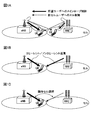
- Downlink CoMP transmission includes Coordinated Scheduling / Coordinated Beamforming (CS / CB) and Joint processing.
- CS / CB is a method of transmitting a shared data channel (PDSCH) only from one transmission / reception point (or radio base station, cell) to one user terminal UE, as shown in FIG.
- Radio resources are allocated in the frequency / space region in consideration of interference from transmission / reception points and interference with other transmission / reception points.
- Joint processing is a method in which precoding is applied to simultaneously transmit a shared data channel from a plurality of transmission / reception points.
- shared data is transmitted from a plurality of transmission / reception points to one user terminal UE.
- Joint transmission JT
- DPS Dynamic Point Selection
- DPB Dynamic Point Blanking
- CoMP transmission is applied to improve the throughput of user terminals existing at the cell edge. For this reason, when a user terminal exists in a cell edge, it controls so that CoMP transmission may be applied.
- the difference in quality information for each cell from the user terminal for example, RSRP (Reference Signal Received Power)), RSRQ (Reference Signal Received Quality), or SINR (Signal Interference plus Noise Ratio), etc. If the difference is less than or equal to the threshold value, that is, if the quality difference between cells is small, it is determined that the user terminal exists at the cell edge, and CoMP transmission is applied.
- the environment to which CoMP transmission / reception is applied includes, for example, a configuration including a plurality of remote radio devices (RRE: Remote Radio Equipment) connected to a radio base station (radio base station eNB) via an optical fiber (RRE configuration) Based control) and a configuration of a radio base station (radio base station eNB) (autonomous distributed control based on an independent base station configuration).
- RRE Remote Radio Equipment
- downlink signals (downlink control signals, downlink data signals, synchronization signals, reference signals, etc.) are transmitted from a plurality of transmission points or specific transmission points to the user terminal.
- the user terminal that has received the downlink signal may, for example, refer to a reference signal (cell-specific reference signal (CRS), user-specific demodulation reference signal (DM-RS), channel state measurement reference).
- CRS cell-specific reference signal
- DM-RS user-specific demodulation reference signal
- CSI-RS Channel State Information-Reference Signal
- reception processing performed by the user terminal include signal processing such as channel estimation, synchronization processing, demodulation processing, and feedback information (CSI) generation processing.
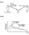
- the received signal level, reception timing, and the like of the downlink signal transmitted from each transmission point may be different (see FIG. 2A, B).
- the user terminal cannot grasp from which transmission point each received downlink signal (for example, a reference signal assigned to a different antenna port (AP: Antenna Port)) is transmitted.
- AP Antenna Port
- the user terminal when receiving processing is performed using a reference signal transmitted from each transmission point, the user terminal considers the geographical position of each transmission point (propagation characteristics of a downlink signal transmitted from each transmission point). It is desirable to perform reception processing. Therefore, the case where the long-term channel characteristics are the same between different antenna ports (APs) is assumed to be “Quasi co-location” (geographically the same), and between each downlink signal is the Quasi co-location. It is considered that each user terminal performs different reception processing depending on whether or not there is.
- Quasi co-location corresponds to a geographically identical case, but is not necessarily limited to a physical proximity.
- reception processing for example, signal processing such as channel estimation, synchronization processing, demodulation processing, and feedback information (CSI) generation processing
- CSI feedback information
- a CRS is transmitted from an AP that is determined to be geographically identical (Quasi co-location), and CSI is transmitted from AP # 15 and AP # 16 that are determined to be geographically separated (not Quasi co-location).
- -As sume a case where an RS is transmitted (see FIG. 2A).
- the user terminal performs reception processing using the CRS as in the conventional case.
- the CSI-RS the user terminal performs independent channel estimation for AP # 15 and AP # 16, and then generates and feeds back channel quality information.
- the assumptions as to whether or not the Quasi co-location is between different APs include, for example, PSS / SSS, CRS, DM-RS (for PDSCH), DM-RS (for ePDCCH), CSI -RS etc. are mentioned.
- the user terminal allocates a PDSCH in consideration of a control signal transmitted from each transmission point, a mapping pattern of reference signals, and the like. It is desirable to specify (rate matching) the resource (RE) to be used. For example, when transmission is performed from a plurality of transmission points (TP1 and TP2) to the user terminal (for example, JT CoMP), the user terminal considers the mapping pattern of PDCCH, CRS, CSI-RS, etc. in TP1 and TP2. It is preferable to perform matching.
- CoMP for example, JT CoMP
- TP1 and TP2 in a system in which a user terminal can be connected to a plurality of transmission points (TP1 to TP3).
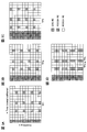
- the user terminal performs rate matching in consideration of mapping patterns such as control signals and reference signals respectively transmitted from TP1 and TP2 (see FIG. 3).
- mapping patterns such as control signals and reference signals respectively transmitted from TP1 and TP2 (see FIG. 3).
- 3A to 3C show examples of mapping patterns in normal subframes TP1 to TP3, and FIG. 3D corresponds to a mapping pattern that takes into account signals transmitted from TP1 and TP2.
- the PDSCH is mapped to an area other than the resource to which the CRS is mapped.
- the user terminal can improve reception processing accuracy by performing reception processing in consideration of the pattern of FIG. 3D.
- CRS is shown as a reference signal in FIG. 3, when CSI-RS is mapped, rate matching is performed in consideration of CSI-RS.
- FIG. 3 shows a normal subframe in which CRS is mapped across the entire frequency band, but the subframe configuration includes MBSFN (Multimedia Broadcast Multicast Service Single Frequency Network) subframe, New Carrier Type (NCT: Application of “New Carrier Type” is also under consideration.
- MBSFN Multimedia Broadcast Multicast Service Single Frequency Network
- NCT Application of “New Carrier Type” is also under consideration.
- MBSFN is a scheme in which a plurality of radio base stations constituting the MBSFN can simultaneously synchronize and transmit the same signal, so that a user terminal can synthesize a signal transmitted from each radio base station by RF (Radio frequency).
- the MBSFN subframe is a subframe in which a portion other than the control channel is a blank period (blank period) and no CRS is assigned to the PDSCH region.
- a new carrier type (also referred to as “extension carrier type”) subframe is a subframe that does not have an existing PDCCH from the top of the subframe to a predetermined OFDM symbol (maximum 3 OFDM symbols) and is not assigned a CRS.
- the rate matching pattern of TP1 + TP2 is equal to the mapping pattern of TP1. That is, the user terminal can perform rate matching considering only the mapping pattern of RE for PDSCH of TP1 using normal subframes.
- the user terminal by performing rate matching in consideration of the mapping pattern and subframe configuration of PDCCH, CRS, and CSI-RS transmitted from a plurality of transmission points, the PDSCH resources of the serving cell and the neighboring cell are reduced. It is possible to specify and perform reception processing. That is, Rel. 11, it is important that the user terminal performs rate matching in consideration of a mapping pattern such as PDCCH, CRS, CSI-RS, and subframe configuration.
- parameter information (PDSCH RE Mapping and Quasi-co) in which PDSCH resource mapping information (PDSCH RE mapping Parameter) and Quasi co-location information (Quasi-co-location Configuration Parameter) are defined for each component carrier (CC).
- PDSCH resource mapping information (PDSCH RE mapping Parameter)
- Quasi co-location information Quasi-co-location Configuration Parameter
- Preparation of a predetermined number (for example, 4 sets) of -location Configuration) and notifying the user terminal is under consideration.
- parameter information including PDSCH resource mapping information and Quasi co-location information in consideration of transmission points and communication environments around the user terminal (hereinafter referred to as “parameter information”).
- a predetermined number for example, four types.
- the said some parameter information is notified to a user terminal by upper layer signaling (for example, RRC signaling).
- RRC signaling for example, RRC signaling.
- an instruction for allowing the user terminal to select specific parameter information from among the four types of parameter information # 1 to # 4 is included in downlink control information (DCI) and dynamically notified to the user terminal. (See FIG. 4).
- DCI downlink control information
- parameter information # 1 to # 4 (PDSCH RE Mapping and Quasi-co-location Configuration # 1- # 4) shown in FIG. 4 is notified to the user terminal by higher layer signaling, and bits corresponding to each parameter information Information (“00”, “01”, “10” or “11”) is included in downlink control information (DCI) and notified to the user terminal.
- DCI downlink control information
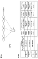
- FIG. 5A shows a case in which DPS CoMP is used in which one transmission / reception point is instantaneously selected from a plurality of transmission / reception points (here, three of TP1, TP2, and TP3) and a shared data channel is transmitted.
- the network dynamically selects one transmission point (radio base station) and transmits a data signal to the user terminal.
- the data signal is transmitted from the transmission point TP1 to the user terminal in subframe # 1, the data signal is transmitted from the transmission point TP2 to the user terminal in subframe # 2, and the subframe # 3 is transmitted.
- the data signal can be transmitted from the transmission point TP3 to the user terminal.
- FIG. 5B shows an example of parameter information (Configuration).
- Parameter information # 1, # 2, and # 3 (Configuration # 1, # 2, and # 3) are parameters of TP1, TP2, and TP3, respectively. It corresponds. Also, the parameter information # 1 to # 3 is notified to the user terminal via higher layer signaling (for example, RRC signaling).
- the CRS pattern includes the number of CRS antenna ports and the shift amount. Thereby, the mapping pattern of CRS can be specified.
- the MBSFN configuration (MBSFN config) corresponds to the MBSFN configuration, and the presence or absence of a CRS pattern in the PDSCH region can be determined from the MBSFN configuration.
- the non-zero power CSI-RS (NZP CSI-RS) is a reference signal that can be used for estimating the desired signal. By notifying the user terminal of the non-zero power CSI-RS pattern (NZP CSI-RS pattern), the CSI-RS The Quasi co-location relationship between RS and DM-RS can be determined.
- Zero power CSI-RS is a reference signal that can be used for interference signal estimation, and PDSCH is not multiplexed. By notifying the user terminal of a zero power CSI-RS pattern (ZP CSI-RS pattern), rate matching can be performed appropriately.
- the PDSCH starting symbol (PDSCH starting symbol) is a parameter indicating a head symbol in which the PDSCH is arranged. Thereby, the user terminal can specify the head symbol of the PDSCH of the adjacent cell. Note that the parameter information in FIG. 5 is an example, and the present invention is not limited to this.
- the identifier indicating each parameter information (PDSCH RE Mapping and Quasi-co-location Configuration) shown in FIG. 5B may be called PQI (PDSCH RE Mapping and Quasi-co-location Indicator).
- the PQI is included in downlink control information (DCI) and notified to the user terminal. For example, when data is transmitted from TP0 to the user terminal in subframe # 1 as described above, the user terminal is notified by downlink control information so that parameter information # 1 is applied. For example, when the relationship between the parameter information and the PQI is shown in FIG. 4, the PQI set in the DCI is “00”.
- DCI format 2D downlink control information
- the DCI format 2D is also being studied as a DCI format used for the CoMP transmission mode (TM10).
- TM10 CoMP transmission mode
- it is considered to set four sets of parameter information for each CC by using the DCI format 2D.
- the PQI when four types of parameter information are set, the PQI can be represented by 2 bits.
- a method of adding 1 bit to be newly added and an information element (for example, scrambling identity) of an existing DCI format to obtain a 2-bit PQI, or a method of newly adding 2 bits can be applied.
- the number of bits of PQI depends on the number of parameter information. When four types are set as shown in FIG. 4 (Configuration # 1- # 4), the number of bits required for PQI is two. . In the present embodiment, the number of bits for PQI is not limited to 2 bits. For example, when eight types of parameter information are set, the number of bits for PQI can be 3 bits. In this case as well, the above method (a method of newly adding 1 bit or 2 bits + a method of combining with a predetermined information element or a method of newly adding 3 bits) can be applied as PQI.
- carrier aggregation CA
- PUSCH downlink control information transmitted at transmission point TP1 (cell 1) is transmitted to another transmission point TP0 (cell 0).
- Can be multiplexed and transmitted (cross-carrier scheduling).
- CIF for setting a carrier identifier (CI: Carrier Indicator) (or CC identifier (CC Indicator)) to identify which transmission point PDSCH corresponds to each downlink control information.
- the DCI format with (Carrier Indicator field) added is applied (see FIGS. 6B and 6C).
- FIG. 6C shows a table (hereinafter also referred to as “table 1”) that defines the relationship between CIF bits and CC identifiers.
- CIF is a field that represents a carrier identifier (CI).
- CI carrier identifier
- a user terminal uses a cell (CC) in which a PDSCH to be demodulated is multiplexed based on bits specified in CIF. Can be specified.
- the number of CIF bits is determined in consideration of the number of CCs to which CA is applied. When CA of up to 5 CCs is assumed, the number of CIF bits is 3 bits.
- the network controls whether to add 3 bits for CIF to DCI according to the presence / absence of cross-carrier scheduling, and transmits information on the presence / absence of DCI setting to higher layer signaling (for example, , RRC signaling) to the user terminal.
- higher layer signaling for example, , RRC signaling
- Boolean indicating whether or not 3-bit CIF exists in DCI can be defined as the basic data type
- the present inventors have focused on using CIF when notifying predetermined parameter information by setting PQI in downlink control information (DCI).
- DCI downlink control information
- DCI downlink control information
- a bit field for PQI is newly set in DCI (for example, DCI format 2D).
- DCI format 2D there are a method of adding one new bit for PQI and combining it with an information element of an existing DCI format (for example, scrambling identity (Nscid)), and a method of adding two new bits for PQI.
- a DCI format 2D can be obtained by adding a PQI bit to the existing DCI format 2C.
- CIF is added to downlink control information (cif_Presence: True)
- the CIF bit is used as an identifier of parameter information (reusing CIF only (Alt. 1)), a bit field (CIF) for CC identifier, It is conceivable to set each bit field for PQI (CIF + PQI (Alt. 2)).
- the CIF is used as the original CC identifier, and a part of the CIF is used as the parameter information identifier, or the CIF is not used as the original CC identifier but as an identifier indicating the parameter information. Use. That is, part or all of the CIF is used as a substitute for the PQI.
- up to four types of parameter information are defined for each CC using a 3-bit CIF, up to two CCs using CoMP can be supported.
- the present inventors have made a signaling method of an identifier indicating parameter information based on a communication form with a user terminal (CoMP transmission presence / absence and transmission form, number of CCs to which CoMP is applied, CIF setting presence / absence, etc.) Inspired to control. Specifically, the network (wireless base station) side controls whether or not to set the bit field for PQI based on the communication form with the user terminal, and determines whether or not the bit field for PQI is set. Signaling to.
- Pqi-Presence is used as a Boolean (a basic data type having two values “true” and “false”) indicating whether or not a bit field for 1-bit or 2-bit PQI exists in DCI. "Is newly defined, and it has been found that the user terminal is notified of the presence / absence of PQI setting by RRC signaling.
- the user terminal can appropriately determine the content indicated by the CIF on the user terminal side.
- the idea was to select a predetermined table based on a predetermined condition from a plurality of tables.
- parameter information may not be required in the user terminal if the CoMP format is CS / CB. Also in this case, as in the case where CoMP is not applied, information (pqi_Presence: False) that does not set the PQI is notified to the user terminal by higher layer signaling (for example, RRC signaling).
- higher layer signaling for example, RRC signaling
- CS / CB CoMP can also set up four types of parameter information and notify the user terminal by higher layer signaling when considering cooperation with DPS or JT CoMP.
- a field for PQI is set (pqi_Presence: True).
- PQI is set in some CCs (for example, CC1) among a plurality of CCs performing CoMP, and PQI is not set in other CCs (for example, CC2). Is also possible.
- the CIF bit is used as an identifier of parameter information (Alt.1, reuse CIF), and the number of CCs is
- a CC identifier bit field (CIF) and a PQI bit field are set (Alt.2, CIF + PQI), respectively.
- an identifier indicating parameter information can be defined for DCI using CIF. That is, since CIF can be used for PQI, control is performed so as not to set a bit field for PQI in DCI (for example, DCI format 2D). In this case, information (pqi_Presence: False) that does not set the PQI is notified from the radio base station to the user terminal by higher layer signaling (for example, RRC signaling).
- higher layer signaling for example, RRC signaling
- control is performed so that PQI is set in DCI.
- information (pqi_Presence: True) for setting the PQI is notified from the radio base station to the user terminal by higher layer signaling (for example, RRC signaling).
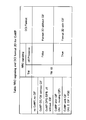
- FIG. 9 is a table that defines the relationship between CIF bits, CC identifiers, and parameter information when CA is performed with five CCs and CoMP is applied with one CC (here, CC0) (hereinafter, “ Table 2 ”).
- parameter information (4 sets) for CC0 can be defined using the CIF free space.
- “001”, “010”, “011”, and “100” in the CIF correspond to CC identifiers of CC1, CC2, CC3, and CC4, respectively, and “000”, “101”, and “110” in the CIF.
- “111” is the identifier of CC0 and corresponds to the parameter information # 1 to # 4 of CC0.
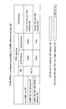
- FIG. 10 is a table (hereinafter referred to as a table) defining the relationship among CIF bits, CC identifiers, and parameter information when CA is performed with two CCs and CoMP is applied with two CCs (here, CC0 and CC1). , Also referred to as “Table 3”).
- parameter information for example, 4 sets ⁇ 2
- CC0 and CC1 when there are two CCs to which CoMP is applied, parameter information (for example, 4 sets ⁇ 2) for CC0 and CC1 can be respectively defined using CIF.
- CIF parameter information # 1 to # 4 of CC0, respectively, and “100”, “101”, “110”, A case where “111” corresponds to parameter information # 1 to # 4 of CC1 is shown.
- CIF is set in downlink control information (cif_Presence: True)
- CIF is used.
- Parameter information of each CC can be set. Also in this case, since it is not necessary to add a new bit field to the downlink control information even when the parameter information is notified, the number of bits of the downlink control information can be saved.
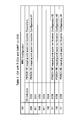
- FIG. 11 shows a case where CA is performed with five CCs and CoMP is applied with three or more CCs (here, three of CC0, CC1, and CC2), CIF bits, PQI bits, CC identifiers, A table (hereinafter also referred to as “table 4”) that defines the relationship with the parameter information is shown.
- the parameter information (4 sets ⁇ 3) for each CC can be defined using CIF bits (for example, 3 bits) and PQI bits (2 bits).
- CIF bits for example, 3 bits
- PQI bits 2 bits.
- “000”, “001”, “010”, “011”, “100” in the CIF correspond to CC0, CC1, CC2, CC3, CC4, respectively, and “00”, “01”, “10” and “11” indicate cases corresponding to parameter information # 1 to # 4 of each CC, respectively.
- the third mode In the third mode, a case where the presence / absence of setting of a field for PQI for DCI (pqi_Presence: True / False) is controlled according to the number of CSI processes (CSI process number) will be described with reference to FIG.
- the number of CSI processes refers to the number of CSI that the user terminal can feed back in one subframe.
- the number of CSI processes is controlled for each CC, and the higher the performance of the user terminal, the higher the number of CSI processes.
- control is performed so that the bit field for PQI is newly set to DCI (for example, DCI format 2D) (pqi_Presence: True), and the user terminal (See FIG. 12B).
- DCI for example, DCI format 2D
- pqi_Presence True
- the number of bits of downlink control information is appropriately controlled according to the communication mode of the user terminal. be able to. Accordingly, it is possible to suppress an increase in overhead of DCI and to appropriately notify the parameter information of each CC to the user terminal.
- the radio base station (transmission point) is based on the communication form with the user terminal (for example, at least one of application / non-application of CoMP, transmission form of CoMP, CC number of CoMP, and presence / absence of CIF setting).
- the presence / absence of field setting for PQI is controlled.
- the user terminal obtains predetermined parameter information based on parameter information notified from the radio base station, downlink control information (for example, DCI format 2D), and information on presence / absence of PQI field setting (pqi_Presence: True / False). It is possible to determine and perform reception processing.
- the contents indicated by the CIF may differ depending on the communication form. Specifically, when the CIF bit is used as an identifier representing a predetermined CC as usual (Table 1 in FIG. 6C) and when the CIF bit is used as an identifier for parameter information (for PQI) (reusing CIF, There are a table 2 in FIG. 9 and a table 3 in FIG. 10) and a case where CIF and PQI are set and used (CIF + PQI, table 4 in FIG. 11).
- the CIF when CoMP is not applied as a communication mode between the user terminal and the radio base station (CA only), the CIF is used as an identifier indicating only a predetermined CC (Table 1).
- CIF when CoMP is applied in two or less CCs as a communication mode between a user terminal and a radio base station, CIF is used as an identifier of CoMP CC parameter information (reusing CIF).
- the CIF When CoMP is applied in three or more CCs, the CIF is used as a CC identifier and is used as an identifier for parameter information of each CC in combination with PQI (using CIF + PQI).
- the user terminal since the contents indicated by the CIF in the tables corresponding to the respective communication modes are different, the user terminal indicates what the CIF included in the received downlink control signal represents (for example, in the tables 1 to 4). It is necessary to perform a reception process after determining which content corresponds to.
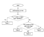
- the user terminal selects a predetermined table based on the presence / absence of PQI setting, the number of CSI processes, the transmission mode (TM), or the PDSCH resource mapping state (parameter information) notified by RRC. Receive processing.
- the user terminal indicates a predetermined table from the four types of tables, the table 1 in FIG. 6C, the table 2 in FIG. 9, the table 3 in FIG. 10, and the table 4 in FIG.
- the contents of these tables are examples, and the number and contents of tables used by the user terminal are not limited to this.
- the user terminal uses Table 4 in FIG. 11 (see FIG. 13A).
- the CIF corresponds to the CC identifier and is used as an identifier indicating parameter information of each cell by combining with the PQI.
- the user terminal uses any one of the tables 1 to 3 based on whether or not CoMP is applied, the number of CoMP CCs, and the like. Note that the presence / absence of PQI setting can be notified from the radio base station to the user terminal by RRC signaling.
- the transmission mode is not the transmission mode (TM10) defined for CoMP
- the CIF is used only as a CC identifier as usual, and selects the table 1 ( (See FIG. 13B).
- the transmission mode is the transmission mode (TM10) defined for CoMP
- one of the tables 2 to 4 is used based on the number of CoMP CCs and the like.
- the user terminal has only 0 or 1 for PDSCH resource mapping state (parameter information) for each CC
- Table 1 is selected (see FIG. 15).
- the parameter information is 2 or more for each CC
- a table can be appropriately selected according to the number of CCs. For example, if there is one CC having two or more parameter information, select table 2, select table 3 if there are two CCs, and select table 4 if there are three or more CCs. Can do.
- the user terminal selects a table in which the correspondence between the CIF and the parameter information is defined based on a predetermined condition. As a result, the reception process can be appropriately performed.
- CIF When CIF is added to downlink control information (cif_Presence: True), use CIF bit as parameter information identifier (reusing CIF only (Alt.1)), CC identifier bit field (CIF) and PQI Each bit field can be set (CIF + PQI (Alt. 2)).
- DCI format 2D is described as an example of the downlink control information format, but the present embodiment is not limited to this.
- PQI may be configured (CIF + PQI) or CIF It may be used as a parameter information identifier (used for PQI) (reusing CIF).
- the radio base station controls the presence / absence of setting for PQI for DCI (pqi_Presence: True / False) to the user terminal. It can be set as the structure to notify.
- Format 2D is replaced with other Format (for example, DCI format 0, 1, 1A, 1B, 1D, 2, 2A, 2B, 2C, 4 ) Can be applied.
- FIG. 17 is a schematic configuration diagram of a radio communication system according to the present embodiment.
- the radio communication system shown in FIG. 17 is a system including, for example, an LTE system or SUPER 3G.
- carrier aggregation in which a plurality of basic frequency blocks (component carriers) with the system bandwidth of the LTE system as one unit is integrated is applied.
- this radio communication system may be called IMT-Advanced, or may be called 4G, FRA (Future Radio Access).
- the radio communication system 1 shown in FIG. 17 includes a radio base station 11 that forms a macro cell C1, and radio base stations 12a and 12b that are arranged in the macro cell C1 and form a small cell C2 that is narrower than the macro cell C1. . Moreover, the user terminal 20 is arrange
- Communication between the user terminal 20 and the radio base station 11 is performed using a carrier having a relatively low frequency band (for example, 2 GHz) and a wide bandwidth (referred to as an existing carrier or a legacy carrier).
- a carrier with a narrow bandwidth in a relatively high frequency band for example, 3.5 GHz
- the same carrier may be used.
- the wireless base station 11 and each wireless base station 12 are wired or wirelessly connected.
- the radio base station 11 and each radio base station 12 are connected to the higher station apparatus 30 and connected to the core network 40 via the higher station apparatus 30.
- the upper station device 30 includes, for example, an access gateway device, a radio network controller (RNC), a mobility management entity (MME), and the like, but is not limited thereto. Further, each radio base station 12 may be connected to a higher station apparatus via the radio base station 11.
- RNC radio network controller
- MME mobility management entity
- the radio base station 11 is a radio base station having a relatively wide coverage, and may be called an eNodeB, a radio base station apparatus, a transmission point, or the like.
- the radio base station 12 is a radio base station having local coverage, and may be called a pico base station, a femto base station, a Home eNodeB, an RRH (Remote Radio Head), a micro base station, a transmission point, or the like. Good.
- RRH Remote Radio Head
- Each user terminal 20 is a terminal that supports various communication schemes such as LTE and LTE-A, and may include not only a mobile communication terminal but also a fixed communication terminal.
- OFDMA Orthogonal Frequency Division Multiple Access
- SC-FDMA Single Carrier Frequency Division Multiple Access
- OFDMA is a multi-carrier transmission scheme that performs communication by dividing a frequency band into a plurality of narrow frequency bands (subcarriers) and mapping data to each subcarrier.
- SC-FDMA is a single-carrier transmission scheme that reduces interference between terminals by dividing the system bandwidth into bands consisting of one or continuous resource blocks for each terminal and using a plurality of terminals with mutually different bands. is there.
- the downlink communication channel includes a PDSCH (Physical Downlink Shared Channel) shared by each user terminal 20 and a downlink L1 / L2 control channel (PDCCH, PCFICH, PHICH, extended PDCCH).
- PDSCH Physical Downlink Shared Channel
- PHICH Physical Hybrid-ARQ Indicator Channel
- PDCCH Physical Downlink Control Channel
- the number of OFDM symbols used for PDCCH is transmitted by PCFICH (Physical Control Format Indicator Channel).
- the HARQ ACK / NACK for PUSCH is transmitted by PHICH (Physical Hybrid-ARQ Indicator Channel).
- PDSCH and PUSCH scheduling information and the like may be transmitted by an extended PDCCH (also called Enhanced Physical Downlink Control Channel, ePDCCH, E-PDCCH, FDM type PDCCH, etc.).
- extended PDCCH also called Enhanced Physical Downlink Control Channel, ePDCCH, E-PDCCH, FDM type PDCCH, etc.
- This enhanced PDCCH enhanced downlink control channel
- PDSCH downlink shared data channel
- the uplink communication channel includes a PUSCH (Physical Uplink Shared Channel) as an uplink data channel shared by each user terminal 20 and a PUCCH (Physical Uplink Control Channel) as an uplink control channel.
- PUSCH Physical Uplink Shared Channel
- PUCCH Physical Uplink Control Channel
- User data and higher control information are transmitted by this PUSCH.
- downlink radio quality information CQI: Channel Quality Indicator
- ACK / NACK and the like are transmitted by PUCCH.
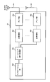
- FIG. 18 is an overall configuration diagram of the radio base station 10 (including the radio base stations 11 and 12) according to the present embodiment.
- the radio base station 10 includes a plurality of transmission / reception antennas 101 for MIMO transmission, an amplifier unit 102, a transmission / reception unit 103, a baseband signal processing unit 104, a call processing unit 105, and a transmission path interface 106. Yes.
- User data transmitted from the radio base station 10 to the user terminal 20 via the downlink is input from the higher station apparatus 30 to the baseband signal processing unit 104 via the transmission path interface 106.
- the baseband signal processing unit 104 performs PDCP layer processing, user data division / combination, RLC layer transmission processing such as RLC (Radio Link Control) retransmission control transmission processing, MAC (Medium Access Control) retransmission control, for example, HARQ transmission processing, scheduling, transmission format selection, channel coding, inverse fast Fourier transform (IFFT) processing, and precoding processing are performed and transferred to each transceiver 103.
- RLC layer transmission processing such as RLC (Radio Link Control) retransmission control transmission processing, MAC (Medium Access Control) retransmission control, for example, HARQ transmission processing, scheduling, transmission format selection, channel coding, inverse fast Fourier transform (IFFT) processing, and precoding processing are performed and transferred to each transceiver 103.
- HARQ transmission processing scheduling, transmission format selection, channel coding, inverse fast Fourier transform (IFFT) processing, and precoding processing are performed and transferred to each transceiver 103.
- IFFT inverse fast Fourier transform
- the baseband signal processing unit 104 notifies the control information for communication in the cell to the user terminal 20 through the broadcast channel.
- the information for communication in the cell includes, for example, the system bandwidth in the uplink or the downlink.
- Each transmission / reception unit 103 converts the baseband signal output by precoding from the baseband signal processing unit 104 for each antenna to a radio frequency band.
- the amplifier unit 102 amplifies the frequency-converted radio frequency signal and transmits the amplified signal using the transmission / reception antenna 101.
- the transmission / reception unit 103 transmits parameter information (PDSCH RE Mapping and Quasi-co-location Configuration), CIF and PQI setting information (cif_Presence, pqi_Presence), downlink control information (DCI), and the like to the user terminal. Functions as a transmission unit.
- radio frequency signals received by the respective transmission / reception antennas 101 are amplified by the amplifier units 102 and frequency-converted by the respective transmission / reception units 103. It is converted into a baseband signal and input to the baseband signal processing unit 104.
- the baseband signal processing unit 104 performs FFT processing, IDFT processing, error correction decoding, MAC retransmission control reception processing, RLC layer, and PDCP layer reception processing on user data included in the input baseband signal.
- the data is transferred to the higher station apparatus 30 via the transmission path interface 106.
- the call processing unit 105 performs call processing such as communication channel setting and release, status management of the radio base station 10, and radio resource management.
- FIG. 19 is an overall configuration diagram of the user terminal 20 according to the present embodiment.
- the user terminal 20 includes a plurality of transmission / reception antennas 201 for MIMO transmission, an amplifier unit 202, a transmission / reception unit (reception unit) 203, a baseband signal processing unit 204, and an application unit 205.
- radio frequency signals received by a plurality of transmission / reception antennas 201 are each amplified by an amplifier unit 202, converted in frequency by a transmission / reception unit 203, and converted into a baseband signal.
- the baseband signal is subjected to FFT processing, error correction decoding, retransmission control reception processing, and the like by the baseband signal processing unit 204.
- downlink user data is transferred to the application unit 205.
- the application unit 205 performs processing related to layers higher than the physical layer and the MAC layer. Also, broadcast information in the downlink data is also transferred to the application unit 205.
- uplink user data is input from the application unit 205 to the baseband signal processing unit 204.
- transmission processing for retransmission control H-ARQ (Hybrid ARQ)
- channel coding precoding
- DFT processing IFFT processing
- the like are performed and transferred to each transmission / reception unit 203.
- the transmission / reception unit 203 converts the baseband signal output from the baseband signal processing unit 204 into a radio frequency band.
- the amplifier unit 202 amplifies the frequency-converted radio frequency signal and transmits the amplified signal using the transmitting / receiving antenna 201.
- the transmission / reception unit 203 receives parameter information (PDSCH RE Mapping and Quasi-co-location Configuration), CIF and PQI setting information (cif_Presence, pqi_Presence), downlink control information (DCI), etc. notified from the radio base station It functions as a part.
- parameter information PDSCH RE Mapping and Quasi-co-location Configuration
- CIF and PQI setting information cif_Presence, pqi_Presence
- DCI downlink control information
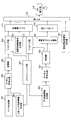
- FIG. 20 is a functional configuration diagram of the baseband signal processing unit 104 and some upper layers included in the radio base station 10 according to the present embodiment. 20 mainly shows a functional configuration for downlink (transmission), the radio base station 10 may include a functional configuration for uplink (reception).
- the radio base station 10 includes an upper layer control information generation unit 300, a data generation unit 301, a channel encoding unit 302, a modulation unit 303, a mapping unit 304, a downlink control information generation unit 305, a channel encoding.
- the higher layer control information generation unit 300 generates higher layer control information for each user terminal 20.
- the higher layer control information is control information for higher layer signaling (for example, RRC signaling), for example, parameter information (PDSCH RE Mapping and Quasi-co-location Configuration), CIF and PQI setting information (cif_Presence, pqi_Presence).
- the data generation unit 301 generates downlink user data for each user terminal 20.
- the downlink user data generated by the data generation unit 301 and the higher layer control information generated by the higher layer control information generation unit 300 are input to the channel coding unit 302 as downlink data transmitted on the PDSCH.
- the channel coding unit 302 performs channel coding on the downlink data for each user terminal 20 according to a coding rate determined based on feedback information from each user terminal 20.
- the modulation unit 303 modulates the channel-coded downlink data according to a modulation scheme determined based on feedback information from each user terminal 20.
- the mapping unit 304 maps the modulated downlink data according to the instruction from the scheduling unit 317.
- the downlink control information generation unit 305 generates downlink control information (DCI) for each user terminal 20.
- the downlink control information includes PDSCH allocation information (DL assisting), PUSCH allocation information (UL grant), and the like.
- the downlink control information generation unit 305 generates downlink control information including an identifier indicating parameter information using a predetermined DCI format (for example, DCI format 2D) according to the communication form with the user terminal.
- the downlink control information generation unit 305 when the number of CCs when applying CoMP is equal to or less than a predetermined number, the downlink control information generation unit 305 generates downlink control information using the CIF bit as an identifier of parameter information (Alt.1, reusing CIF). Also, when the number of CCs is greater than a predetermined number, the downlink control information generation unit 305 sets the CC identifier bit field (CIF) and the PQI bit field, respectively, and generates downlink control information (Alt. 2, CIF + PQI).
- CIF CC identifier bit field
- PQI PQI bit field
- the downlink control information generated by the downlink control information generation unit 305 is input to the channel coding unit 307 as downlink control information transmitted on the PDCCH or the extended PDCCH.
- the channel coding unit 307 performs channel coding on the input downlink control information according to the coding rate instructed from the scheduling unit 317 described later.
- Modulation section 308 modulates the channel-coded downlink control information according to the modulation scheme instructed from scheduling section 317.
- downlink control information transmitted on the PDCCH is input from the modulation unit 308 to the control channel multiplexing unit 309 and multiplexed.
- the downlink control information multiplexed by the control channel multiplexing unit 309 is interleaved by the interleaving unit 310.
- the interleaved downlink control information is input to the IFFT unit 312 together with the measurement reference signals (CSI-RS, CRS, etc.) generated by the measurement reference signal generation unit 311.
- downlink control information transmitted on the extended PDCCH is input from the modulation unit 308 to the mapping unit 313.
- the mapping unit 313 maps the downlink control information according to an instruction from the scheduling unit 317 described later.
- the mapped downlink control information includes downlink data transmitted on the PDSCH (that is, downlink data mapped by the mapping unit 304), and a demodulation reference signal (DM-RS) generated by the demodulation reference signal generation unit 314. At the same time, it is input to the weight multiplier 315.
- Weight multiplying section 315 multiplies downlink data transmitted by PDCSH, downlink control information transmitted by enhanced PDCCH, and a demodulation reference signal by a precoding weight specific to user terminal 20, and performs precoding.
- the precoded transmission data is input to the IFFT unit 312 and converted from a frequency domain signal to a time-series signal by inverse fast Fourier transform.
- a cyclic prefix (CP) functioning as a guard interval is inserted by the CP insertion unit 316 into the output signal from the IFFT unit 312 and output to the transmission / reception unit 103.
- CP cyclic prefix
- the scheduling unit 317 performs scheduling of downlink user data transmitted on the PDSCH, downlink control information transmitted on the enhanced PDCCH, and downlink control information transmitted on the PDCCH.
- the scheduling unit 317 includes instruction information from the higher station apparatus 30 (for example, information related to a communication form with the user terminal), feedback information from each user terminal 20 (for example, CQI (Channel Quality Indicator), RI Based on CSI (Channel State Information) including (Rank Indicator) etc., radio resources are allocated.
- the scheduling unit 317 performs PQI and / or PQI based on the communication mode in the user terminal (for example, at least one of CoMP application status, CoMP transmission mode, CoMP CC count, and CIF setting status). It functions as a control unit that controls whether CIF is set. Also, the scheduling unit (control unit) 317 instructs the upper layer control information generation unit 300 to set PQI and CIF, and to generate parameter information. Further, it is possible to instruct the downlink control information generation unit 305 to specify the identifier of the parameter information included in the downlink control information.
- the higher layer control information generation unit 300 generates parameter information, CIF and PQI setting information (cif_Presence, pqi_Presence), and the like. These pieces of information are notified to the user terminal 20 by higher layer signaling (for example, RRC signaling).
- higher layer signaling for example, RRC signaling
- FIG. 21 is a functional configuration diagram of the baseband signal processing unit 204 included in the user terminal 20.
- the user terminal 20 includes, as a downlink (reception) functional configuration, a CP removal unit 401, an FFT unit 402, a demapping unit 403, a deinterleaving unit 404, a PDCCH demodulation unit 405, a CIF determination unit 406, a PDSCH demodulation unit 407, A channel estimation unit 408 is provided.
- the cyclic prefix (CP) is removed from the downlink signal received as reception data from the radio base station 10 by the CP removal unit 401.
- the downlink signal from which the CP is removed is input to the FFT unit 402.
- the FFT unit 402 performs fast Fourier transform (FFT) on the downlink signal to convert the signal in the time domain to the signal in the frequency domain, and inputs the signal to the demapping unit 403.
- the demapping unit 403 demaps the downlink signal. Note that the demapping process by the demapping unit 403 is performed based on higher layer control information input from the application unit 205.
- the downlink control information output from the demapping unit 403 is deinterleaved by the deinterleaving unit 404.
- the PDCCH demodulation unit 405 performs blind decoding, demodulation, channel decoding, and the like of downlink control information (DCI) output from the deinterleaving unit 404 based on a channel estimation result by a channel estimation unit 408 described later.
- DCI downlink control information
- the CIF determination unit (selection unit) 406 selects a predetermined table from a plurality of tables (for example, tables 1 to 4) in which the contents indicated by the CIF bit are defined. Select. For example, the CIF determination unit 406 performs predetermined processing based on at least one of the presence / absence of a bit field for PQI (pqi_Presence: True / False), the transmission mode, the number of CSI processes, and the number of PDSCH resource mapping states (parameter information). Can be selected (FIGS. 13 to 15 above).
- the user terminal determines parameter information (PDSCH RE Mapping and Quasi-co-location Configuration) and performs reception processing.
- PDSCH RE Mapping and Quasi-co-location Configuration parameters information
- the PDSCH demodulation unit 407 performs demodulation, channel decoding, and the like of downlink data output from the demapping unit 403 based on the channel estimation result by the channel estimation unit 408. Specifically, the PDSCH demodulator 407 demodulates the PDSCH assigned to the terminal based on the downlink control information demodulated by the PDCCH demodulator 405, and downloads downlink data (downlink user data and higher layer control addressed to the terminal). Information).
- the channel estimation unit 408 performs channel estimation using a demodulation reference signal (DM-RS), a measurement reference signal (CRS, CSI-RS), and the like.
- Channel estimation section 408 outputs a channel estimation result based on measurement reference signals (CRS, CSI-RS) to PDCCH demodulation section 405.
- channel estimation section 408 outputs the channel estimation result based on the demodulation reference signal (DM-RS) to PDSCH demodulation section 407.
Landscapes
- Engineering & Computer Science (AREA)
- Signal Processing (AREA)
- Computer Networks & Wireless Communication (AREA)
- Computer Security & Cryptography (AREA)
- Mobile Radio Communication Systems (AREA)
Priority Applications (4)
| Application Number | Priority Date | Filing Date | Title |
|---|---|---|---|
| EP13852898.9A EP2919526B1 (de) | 2012-11-12 | 2013-10-23 | Funkkommunikationsverfahren, funkkommunikationssystem, funkbasisstation und benutzerendgerät |
| CN201380057979.XA CN104782184A (zh) | 2012-11-12 | 2013-10-23 | 无线通信方法、无线通信系统、无线基站以及用户终端 |
| CN201810462358.4A CN108633078B (zh) | 2012-11-12 | 2013-10-23 | 无线通信方法、无线基站以及用户终端 |
| US14/442,260 US9742534B2 (en) | 2012-11-12 | 2013-10-23 | Radio communication method, radio communication system, radio base station and user terminal |
Applications Claiming Priority (2)
| Application Number | Priority Date | Filing Date | Title |
|---|---|---|---|
| JP2012-248789 | 2012-11-12 | ||
| JP2012248789A JP2014096777A (ja) | 2012-11-12 | 2012-11-12 | 無線通信方法、無線通信システム、無線基地局及びユーザ端末 |
Publications (1)
| Publication Number | Publication Date |
|---|---|
| WO2014073375A1 true WO2014073375A1 (ja) | 2014-05-15 |
Family
ID=50684486
Family Applications (1)
| Application Number | Title | Priority Date | Filing Date |
|---|---|---|---|
| PCT/JP2013/078656 WO2014073375A1 (ja) | 2012-11-12 | 2013-10-23 | 無線通信方法、無線通信システム、無線基地局及びユーザ端末 |
Country Status (5)
| Country | Link |
|---|---|
| US (1) | US9742534B2 (de) |
| EP (1) | EP2919526B1 (de) |
| JP (1) | JP2014096777A (de) |
| CN (2) | CN108633078B (de) |
| WO (1) | WO2014073375A1 (de) |
Cited By (1)
| Publication number | Priority date | Publication date | Assignee | Title |
|---|---|---|---|---|
| US20230087900A1 (en) * | 2016-03-31 | 2023-03-23 | Samsung Electronics Co., Ltd. | Method and apparatus for transmitting and receiving reference signals in wireless communication |
Families Citing this family (14)
| Publication number | Priority date | Publication date | Assignee | Title |
|---|---|---|---|---|
| JP6325249B2 (ja) * | 2013-12-26 | 2018-05-16 | 株式会社Nttドコモ | ユーザ端末及び無線通信方法 |
| CN106559879B (zh) | 2015-09-25 | 2019-08-02 | 中兴通讯股份有限公司 | 信息发送及确定、关系确定的方法及装置 |
| JP6663256B2 (ja) * | 2016-03-11 | 2020-03-11 | 株式会社Nttドコモ | 無線通信システム及び管理装置 |
| CN112887000B (zh) | 2016-05-31 | 2022-07-15 | 中兴通讯股份有限公司 | 信息反馈方法、装置及系统 |
| CN109644488B (zh) * | 2016-08-31 | 2022-10-11 | 株式会社Ntt都科摩 | 用户终端以及无线通信方法 |
| EP3550913A4 (de) | 2017-01-25 | 2019-12-11 | Huawei Technologies Co., Ltd. | Kommunikationsverfahren, netzwerkseitige vorrichtung und endgerätevorrichtung |
| CN108809573B (zh) | 2017-05-05 | 2023-09-29 | 华为技术有限公司 | 确定天线端口的qcl的方法和设备 |
| US11812433B2 (en) * | 2017-11-17 | 2023-11-07 | Ntt Docomo, Inc. | User terminal and radio communication method |
| JP7179856B2 (ja) * | 2018-08-09 | 2022-11-29 | 株式会社Nttドコモ | 端末及び通信方法 |
| JP7193550B2 (ja) * | 2018-10-31 | 2022-12-20 | 株式会社Nttドコモ | 端末、無線通信方法及びシステム |
| US11412422B2 (en) * | 2019-03-14 | 2022-08-09 | Ofinno, Llc | Handover in unlicensed band |
| CN114244484A (zh) * | 2019-03-29 | 2022-03-25 | 华为技术有限公司 | 通信处理方法和装置 |
| EP4024936A4 (de) * | 2019-08-26 | 2023-05-17 | Ntt Docomo, Inc. | Endgerät und drahtloskommunikationsverfahren |
| US11888610B2 (en) * | 2020-02-26 | 2024-01-30 | Qualcomm Incorporated | Method and apparatus for positioning with LTE-NR dynamic spectrum sharing (DSS) |
Family Cites Families (23)
| Publication number | Priority date | Publication date | Assignee | Title |
|---|---|---|---|---|
| CN101467413B (zh) * | 2006-06-13 | 2013-08-21 | 高通股份有限公司 | 用于在无线通信系统中发送和接收导频的方法和装置 |
| JP4940115B2 (ja) * | 2007-07-13 | 2012-05-30 | 株式会社日立製作所 | 無線通信システム、無線端末および無線基地局 |
| WO2010013961A2 (en) * | 2008-07-30 | 2010-02-04 | Lg Electronics Inc. | Method and apparatus of monitoring pdcch in wireless communication system |
| JP2010279009A (ja) * | 2009-04-27 | 2010-12-09 | Ntt Docomo Inc | 移動端末装置及び無線通信方法 |
| CN102668671B (zh) * | 2009-12-17 | 2015-10-14 | 松下电器(美国)知识产权公司 | 无线发送装置和控制信号发送方法 |
| KR101799272B1 (ko) * | 2010-02-03 | 2017-11-20 | 엘지전자 주식회사 | 무선 통신 시스템에서 제어 정보의 전송 방법 및 장치 |
| MX2012009372A (es) * | 2010-02-15 | 2012-09-12 | Panasonic Corp | Dispositivo de transmision y metodo de transmision. |
| JP5072986B2 (ja) * | 2010-02-15 | 2012-11-14 | 株式会社エヌ・ティ・ティ・ドコモ | 無線通信システム、基地局装置及びユーザ端末 |
| EP2398273B1 (de) * | 2010-06-18 | 2018-02-14 | Acer Incorporated | Verfahren zur handhabung von pufferstatusberichten und kommunikationsvorrichtung damit |
| US8743799B2 (en) * | 2010-06-24 | 2014-06-03 | Nokia Siemens Networks Oy | Change of rate matching modes in presence of channel state information reference signal transmission |
| KR20120015228A (ko) * | 2010-08-11 | 2012-02-21 | 주식회사 팬택 | 다중 요소 반송파 시스템에서 전력조정에 관한 정보의 전송장치 및 방법 |
| KR20120063586A (ko) * | 2010-12-08 | 2012-06-18 | 삼성전자주식회사 | 분산 안테나를 적용하는 이동 통신 시스템에서 채널상태 정보 송수신 방법 및 장치 |
| CN102594528B (zh) * | 2011-01-10 | 2017-07-07 | 夏普株式会社 | 非周期信道状态信息反馈的触发方法和设备 |
| WO2012148162A2 (ko) * | 2011-04-25 | 2012-11-01 | 엘지전자 주식회사 | 무선 접속 시스템에서 참조 신호 송수신 방법 및 이를 위한 단말 |
| CN102255689B (zh) * | 2011-07-08 | 2018-05-04 | 中兴通讯股份有限公司 | 一种信道状态信息的处理方法、装置及系统 |
| EP2733999A4 (de) * | 2011-07-15 | 2015-03-11 | Fujitsu Ltd | Sendeverfahren für referenztonsymbole, basisstation und benutzergerät |
| US9794955B2 (en) * | 2011-08-15 | 2017-10-17 | Texas Instruments Incorporated | Configuration of CSI-RS for CoMP feedback |
| US20130128821A1 (en) * | 2011-11-18 | 2013-05-23 | Nokia Siemens Networks Oy | Demodulation Reference Signal Arrangement For Uplink Coordinated Multi-Point Reception |
| US8953478B2 (en) * | 2012-01-27 | 2015-02-10 | Intel Corporation | Evolved node B and method for coherent coordinated multipoint transmission with per CSI-RS feedback |
| WO2013133678A1 (ko) * | 2012-03-09 | 2013-09-12 | 엘지전자 주식회사 | 신호 송수신 방법 및 이를 위한 장치 |
| US9083479B2 (en) * | 2012-05-11 | 2015-07-14 | Intel Corporation | Signaling for downlink coordinated multipoint in a wireless communication system |
| US9307521B2 (en) * | 2012-11-01 | 2016-04-05 | Samsung Electronics Co., Ltd. | Transmission scheme and quasi co-location assumption of antenna ports for PDSCH of transmission mode 10 for LTE advanced |
| US9521664B2 (en) * | 2012-11-02 | 2016-12-13 | Qualcomm Incorporated | EPDCCH resource and quasi-co-location management in LTE |
-
2012
- 2012-11-12 JP JP2012248789A patent/JP2014096777A/ja active Pending
-
2013
- 2013-10-23 CN CN201810462358.4A patent/CN108633078B/zh active Active
- 2013-10-23 EP EP13852898.9A patent/EP2919526B1/de active Active
- 2013-10-23 WO PCT/JP2013/078656 patent/WO2014073375A1/ja active Application Filing
- 2013-10-23 US US14/442,260 patent/US9742534B2/en active Active
- 2013-10-23 CN CN201380057979.XA patent/CN104782184A/zh active Pending
Non-Patent Citations (5)
| Title |
|---|
| "Feasibility Study for Evolved UTRA and UTRAN", 3GPP, TR25.912 (V7.1.0, September 2006 (2006-09-01) |
| NOKIA SIEMENS NETWORKS ET AL.: "Remaining details of downlink control signaling design for CoMP", 3GPP TSG-RAN WG1 MEETING #70BIS R1-124179, 12 October 2012 (2012-10-12), XP050662088 * |
| NTT DOCOMO: "Downlink Control Signaling for Rel-11 CoMP", 3GPP TSG RAN WG1 MEETING #70BIS R1-124251, 12 October 2012 (2012-10-12), XP050662158 * |
| See also references of EP2919526A4 |
| ZTE ET AL.: "Way Forward on downlink control signalling for PDSCH RE mapping and quasi-co-location of CSI-RS and DMRS for TM10", 3GPP TSG RAN WG1 #70BIS R1-124623, 12 October 2012 (2012-10-12), XP050662485 * |
Cited By (1)
| Publication number | Priority date | Publication date | Assignee | Title |
|---|---|---|---|---|
| US20230087900A1 (en) * | 2016-03-31 | 2023-03-23 | Samsung Electronics Co., Ltd. | Method and apparatus for transmitting and receiving reference signals in wireless communication |
Also Published As
| Publication number | Publication date |
|---|---|
| CN108633078B (zh) | 2022-08-02 |
| CN104782184A (zh) | 2015-07-15 |
| EP2919526A4 (de) | 2016-07-13 |
| CN108633078A (zh) | 2018-10-09 |
| US9742534B2 (en) | 2017-08-22 |
| JP2014096777A (ja) | 2014-05-22 |
| EP2919526A1 (de) | 2015-09-16 |
| EP2919526B1 (de) | 2019-01-09 |
| US20160254888A1 (en) | 2016-09-01 |
Similar Documents
| Publication | Publication Date | Title |
|---|---|---|
| JP6076044B2 (ja) | 無線通信方法、無線通信システム、無線基地局及びユーザ端末 | |
| CN108633078B (zh) | 无线通信方法、无线基站以及用户终端 | |
| JP5325928B2 (ja) | チャネル状態情報通知方法、無線基地局装置、ユーザ端末及び無線通信システム | |
| JP6095991B2 (ja) | 無線基地局、ユーザ端末及び無線通信方法 | |
| US9634808B2 (en) | Radio communication system, radio communication method, user terminal and radio base station | |
| JP5771177B2 (ja) | 無線基地局、ユーザ端末、無線通信システム及び無線通信方法 | |
| JP6212188B2 (ja) | 無線通信方法、無線基地局及びユーザ端末 | |
| WO2013168794A1 (ja) | ブラインド復号方法、無線基地局、ユーザ端末及び無線通信システム | |
| EP2836008B1 (de) | Kommunikationssystem, mobilkommunikationsendgerät, lan-basisstationsvorrichtung und kommunikationsverfahren | |
| WO2013168750A1 (ja) | 無線基地局、ユーザ端末、無線通信システム及び無線通信方法 | |
| WO2014002944A1 (ja) | 無線通信システム、無線基地局装置、ユーザ端末及び通信制御方法 | |
| JP6150487B2 (ja) | ユーザ端末、無線基地局、無線通信システム及び無線通信方法 | |
| JP5612770B2 (ja) | 無線通信システム、無線通信方法、無線基地局装置及びユーザ端末 | |
| JP5785459B2 (ja) | 通信システム、基地局装置、移動端末装置及び通信方法 | |
| JP2013251698A (ja) | 無線通信システム、無線基地局装置及び無線通信方法 | |
| JP2014155165A (ja) | 無線基地局、ユーザ端末及び無線通信方法 | |
| WO2014069381A1 (ja) | 無線基地局、ユーザ端末、無線通信システム及び無線通信方法 | |
| WO2014069164A1 (ja) | 無線通信方法、無線通信システム、無線基地局及びユーザ端末 | |
| JP5970595B2 (ja) | 無線基地局装置、ユーザ端末及び無線通信方法 |
Legal Events
| Date | Code | Title | Description |
|---|---|---|---|
| 121 | Ep: the epo has been informed by wipo that ep was designated in this application |
Ref document number: 13852898 Country of ref document: EP Kind code of ref document: A1 |
|
| NENP | Non-entry into the national phase |
Ref country code: DE |
|
| WWE | Wipo information: entry into national phase |
Ref document number: 14442260 Country of ref document: US |
|
| WWE | Wipo information: entry into national phase |
Ref document number: 2013852898 Country of ref document: EP |