WO2014073326A1 - 電動義手 - Google Patents
電動義手 Download PDFInfo
- Publication number
- WO2014073326A1 WO2014073326A1 PCT/JP2013/077762 JP2013077762W WO2014073326A1 WO 2014073326 A1 WO2014073326 A1 WO 2014073326A1 JP 2013077762 W JP2013077762 W JP 2013077762W WO 2014073326 A1 WO2014073326 A1 WO 2014073326A1
- Authority
- WO
- WIPO (PCT)
- Prior art keywords
- wire
- motor
- polymer actuator
- finger
- winding
- Prior art date
- Legal status (The legal status is an assumption and is not a legal conclusion. Google has not performed a legal analysis and makes no representation as to the accuracy of the status listed.)
- Ceased
Links
Images



Classifications
-
- A—HUMAN NECESSITIES
- A61—MEDICAL OR VETERINARY SCIENCE; HYGIENE
- A61F—FILTERS IMPLANTABLE INTO BLOOD VESSELS; PROSTHESES; DEVICES PROVIDING PATENCY TO, OR PREVENTING COLLAPSING OF, TUBULAR STRUCTURES OF THE BODY, e.g. STENTS; ORTHOPAEDIC, NURSING OR CONTRACEPTIVE DEVICES; FOMENTATION; TREATMENT OR PROTECTION OF EYES OR EARS; BANDAGES, DRESSINGS OR ABSORBENT PADS; FIRST-AID KITS
- A61F2/00—Filters implantable into blood vessels; Prostheses, i.e. artificial substitutes or replacements for parts of the body; Appliances for connecting them with the body; Devices providing patency to, or preventing collapsing of, tubular structures of the body, e.g. stents
- A61F2/50—Prostheses not implantable in the body
- A61F2/68—Operating or control means
- A61F2/70—Operating or control means electrical
-
- A—HUMAN NECESSITIES
- A61—MEDICAL OR VETERINARY SCIENCE; HYGIENE
- A61F—FILTERS IMPLANTABLE INTO BLOOD VESSELS; PROSTHESES; DEVICES PROVIDING PATENCY TO, OR PREVENTING COLLAPSING OF, TUBULAR STRUCTURES OF THE BODY, e.g. STENTS; ORTHOPAEDIC, NURSING OR CONTRACEPTIVE DEVICES; FOMENTATION; TREATMENT OR PROTECTION OF EYES OR EARS; BANDAGES, DRESSINGS OR ABSORBENT PADS; FIRST-AID KITS
- A61F2/00—Filters implantable into blood vessels; Prostheses, i.e. artificial substitutes or replacements for parts of the body; Appliances for connecting them with the body; Devices providing patency to, or preventing collapsing of, tubular structures of the body, e.g. stents
- A61F2/50—Prostheses not implantable in the body
- A61F2/54—Artificial arms or hands or parts thereof
- A61F2/58—Elbows; Wrists ; Other joints; Hands
- A61F2/583—Hands; Wrist joints
-
- A—HUMAN NECESSITIES
- A61—MEDICAL OR VETERINARY SCIENCE; HYGIENE
- A61F—FILTERS IMPLANTABLE INTO BLOOD VESSELS; PROSTHESES; DEVICES PROVIDING PATENCY TO, OR PREVENTING COLLAPSING OF, TUBULAR STRUCTURES OF THE BODY, e.g. STENTS; ORTHOPAEDIC, NURSING OR CONTRACEPTIVE DEVICES; FOMENTATION; TREATMENT OR PROTECTION OF EYES OR EARS; BANDAGES, DRESSINGS OR ABSORBENT PADS; FIRST-AID KITS
- A61F2/00—Filters implantable into blood vessels; Prostheses, i.e. artificial substitutes or replacements for parts of the body; Appliances for connecting them with the body; Devices providing patency to, or preventing collapsing of, tubular structures of the body, e.g. stents
- A61F2/50—Prostheses not implantable in the body
- A61F2/54—Artificial arms or hands or parts thereof
- A61F2/58—Elbows; Wrists ; Other joints; Hands
- A61F2/583—Hands; Wrist joints
- A61F2/586—Fingers
-
- B—PERFORMING OPERATIONS; TRANSPORTING
- B25—HAND TOOLS; PORTABLE POWER-DRIVEN TOOLS; MANIPULATORS
- B25J—MANIPULATORS; CHAMBERS PROVIDED WITH MANIPULATION DEVICES
- B25J15/00—Gripping heads and other end effectors
- B25J15/0009—Gripping heads and other end effectors comprising multi-articulated fingers, e.g. resembling a human hand
-
- A—HUMAN NECESSITIES
- A61—MEDICAL OR VETERINARY SCIENCE; HYGIENE
- A61F—FILTERS IMPLANTABLE INTO BLOOD VESSELS; PROSTHESES; DEVICES PROVIDING PATENCY TO, OR PREVENTING COLLAPSING OF, TUBULAR STRUCTURES OF THE BODY, e.g. STENTS; ORTHOPAEDIC, NURSING OR CONTRACEPTIVE DEVICES; FOMENTATION; TREATMENT OR PROTECTION OF EYES OR EARS; BANDAGES, DRESSINGS OR ABSORBENT PADS; FIRST-AID KITS
- A61F2/00—Filters implantable into blood vessels; Prostheses, i.e. artificial substitutes or replacements for parts of the body; Appliances for connecting them with the body; Devices providing patency to, or preventing collapsing of, tubular structures of the body, e.g. stents
- A61F2/50—Prostheses not implantable in the body
- A61F2002/5072—Prostheses not implantable in the body having spring elements
- A61F2002/5073—Helical springs, e.g. having at least one helical spring
-
- A—HUMAN NECESSITIES
- A61—MEDICAL OR VETERINARY SCIENCE; HYGIENE
- A61F—FILTERS IMPLANTABLE INTO BLOOD VESSELS; PROSTHESES; DEVICES PROVIDING PATENCY TO, OR PREVENTING COLLAPSING OF, TUBULAR STRUCTURES OF THE BODY, e.g. STENTS; ORTHOPAEDIC, NURSING OR CONTRACEPTIVE DEVICES; FOMENTATION; TREATMENT OR PROTECTION OF EYES OR EARS; BANDAGES, DRESSINGS OR ABSORBENT PADS; FIRST-AID KITS
- A61F2/00—Filters implantable into blood vessels; Prostheses, i.e. artificial substitutes or replacements for parts of the body; Appliances for connecting them with the body; Devices providing patency to, or preventing collapsing of, tubular structures of the body, e.g. stents
- A61F2/50—Prostheses not implantable in the body
- A61F2002/5093—Tendon- or ligament-replacing cables
-
- A—HUMAN NECESSITIES
- A61—MEDICAL OR VETERINARY SCIENCE; HYGIENE
- A61F—FILTERS IMPLANTABLE INTO BLOOD VESSELS; PROSTHESES; DEVICES PROVIDING PATENCY TO, OR PREVENTING COLLAPSING OF, TUBULAR STRUCTURES OF THE BODY, e.g. STENTS; ORTHOPAEDIC, NURSING OR CONTRACEPTIVE DEVICES; FOMENTATION; TREATMENT OR PROTECTION OF EYES OR EARS; BANDAGES, DRESSINGS OR ABSORBENT PADS; FIRST-AID KITS
- A61F2/00—Filters implantable into blood vessels; Prostheses, i.e. artificial substitutes or replacements for parts of the body; Appliances for connecting them with the body; Devices providing patency to, or preventing collapsing of, tubular structures of the body, e.g. stents
- A61F2/50—Prostheses not implantable in the body
- A61F2/68—Operating or control means
- A61F2002/6854—Operating or control means for locking or unlocking a joint
-
- A—HUMAN NECESSITIES
- A61—MEDICAL OR VETERINARY SCIENCE; HYGIENE
- A61F—FILTERS IMPLANTABLE INTO BLOOD VESSELS; PROSTHESES; DEVICES PROVIDING PATENCY TO, OR PREVENTING COLLAPSING OF, TUBULAR STRUCTURES OF THE BODY, e.g. STENTS; ORTHOPAEDIC, NURSING OR CONTRACEPTIVE DEVICES; FOMENTATION; TREATMENT OR PROTECTION OF EYES OR EARS; BANDAGES, DRESSINGS OR ABSORBENT PADS; FIRST-AID KITS
- A61F2/00—Filters implantable into blood vessels; Prostheses, i.e. artificial substitutes or replacements for parts of the body; Appliances for connecting them with the body; Devices providing patency to, or preventing collapsing of, tubular structures of the body, e.g. stents
- A61F2/50—Prostheses not implantable in the body
- A61F2/68—Operating or control means
- A61F2/70—Operating or control means electrical
- A61F2002/701—Operating or control means electrical operated by electrically controlled means, e.g. solenoids or torque motors
-
- B—PERFORMING OPERATIONS; TRANSPORTING
- B25—HAND TOOLS; PORTABLE POWER-DRIVEN TOOLS; MANIPULATORS
- B25J—MANIPULATORS; CHAMBERS PROVIDED WITH MANIPULATION DEVICES
- B25J15/00—Gripping heads and other end effectors
- B25J15/08—Gripping heads and other end effectors having finger members
- B25J15/083—Gripping heads and other end effectors having finger members with means for locking the fingers in an open or closed position
Definitions
- the present invention relates to an electric prosthesis in which a plurality of fingers are bent and extended using a drive source that operates by energization.
- a motor that operates by energization is used as a drive source, and the rotation of the motor is transmitted to a plurality of finger parts via a drive mechanism, and the fingers are bent and extended so as to grasp the object to be grasped.
- Various electric prostheses have been developed (see, for example, Patent Document 1).
- this motor a small motor is used from the viewpoint of mounting on an electric prosthesis.
- an electric prosthetic hand using a motor as a drive source can grip a target object by largely bending or displacing a finger part.
- the torque generated by a small motor is small. For this reason, it is difficult to stably grasp the grasped object with the finger portion.
- the present invention has been made in view of such circumstances, and the object thereof is to stably hold a gripping object while taking advantage of a motor capable of greatly displacing a finger portion. It is to provide an electric prosthesis.
- An electric prosthetic hand that solves the above problems includes a plurality of finger portions that bend and extend with the joint portion as a fulcrum, a wire that is disposed along the finger portion via the joint portion, and a wire wound around the wire.
- the finger By taking the wire along the length direction and pulling it in the bending direction, the finger is bent, and the polymer material is formed in a long shape and placed in the middle of the wire, voltage application A polymer actuator that elastically deforms in accordance with the application of the voltage, and that expands and contracts in the axial direction by restoring the original shape in response to the stop of voltage application, and the motor and the polymer
- a lock mechanism that restricts relative movement between one of the actuators and the wire, and the polymer actuator has a state in which the relative movement is restricted by the lock mechanism. In that expands and contracts, in which pulls along the wire in the bending direction.
- the motor and the polymer actuator are used as the drive source.
- the polymer actuator arranged in the middle of the wire elastically deforms when a voltage is applied, and expands and contracts along the axial direction by restoring the original shape when the voltage application is stopped. .
- the relative movement between one of the motor and the polymer actuator and the wire is restricted by the lock mechanism.
- the above-mentioned expansion / contraction operation of the polymer actuator is performed in a state where relative movement is restricted by the lock mechanism.
- the wire is further pulled in the bending direction.
- the movement of the wire is transmitted to each part of the finger part via the joint part, and the finger part is further bent with the joint part as a fulcrum.
- the motor has the characteristic that the displacement is large but the output torque is small
- the polymer actuator has the characteristic that the displacement is small but the output torque is large.
- the wire when the finger is bent or displaced greatly, the wire may be pulled in the bending direction by a motor.
- the wire when the finger part is pressed against the object to be grasped with a strong force to grasp the object to be grasped, the wire may be pulled in the bending direction with a strong force by the polymer actuator.
- the characteristics of the motor are supplemented by the polymer actuator.
- the operation of bending or displacing the plurality of finger portions to a position approaching the grasped object is performed by a motor, and the operation of grasping the grasped object by the plurality of finger portions is performed by a polymer actuator. . By doing so, it is possible to stably grip the object to be gripped while taking advantage of the motor that can greatly displace the finger portion.
- the lock mechanism allows the motor to rotate in the winding direction when the wire is wound by the motor.
- the relative movement of the wire with the motor is restricted by restricting the rotation of the motor in the direction opposite to the winding direction.
- the polymer actuator is fixed to the wire, is extended when the wire is wound by the motor, and is contracted in a state where the relative movement is restricted by the lock mechanism.
- the polymer actuator fixed to the wire is extended. Therefore, the extended polymer actuator moves in the bending direction together with the wire.
- the movement of the wire is transmitted to each part of the finger part via the joint part, and is largely bent or displaced using the joint part as a fulcrum to a position where the plurality of finger parts approach the grasped object.
- the rotation of the motor in the direction opposite to the winding direction is restricted by the lock mechanism, and the relative movement of the wire with the motor is restricted.
- the polymer actuator is contracted under the restriction of the relative movement.
- the wire is further pulled in the bending direction with respect to the length direction.
- the movement of the wire is transmitted to each part of the finger part via the joint part, and the finger part is further bent with the joint part as a fulcrum. A plurality of fingers are pressed against the object to be grasped with a strong force, and the object to be grasped is stably grasped.
- the wire is provided so as to be movable along the length direction of the polymer actuator with respect to the polymer actuator, and the polymer actuator has an end close to the finger portion in the axial direction. A fixed end at the portion, and a movable end at the end close to the motor, and the lock mechanism does not lock the wire to the movable end when the wire is wound by the motor. Relative movement with the polymer actuator is allowed.
- the lock mechanism restricts the relative movement between the wire and the polymer actuator by locking the wire to the movable end. . It is preferable that the polymer actuator is contracted when the wire is wound by the motor and is extended in a state where the relative movement is restricted by the lock mechanism.
- the wire when winding the wire by the motor, the wire is pulled in the bending direction.
- the polymer actuator is contracted, and its movable end (end near the motor) approaches the fixed end (end near the finger).
- the lock mechanism does not lock the wire to the movable end. Therefore, relative movement of the wire with the polymer actuator is allowed, and the wire moves to the motor side. This movement of the wire is transmitted to each part of the finger part via the joint part, and is largely bent or displaced with the joint part as a fulcrum to a position where the plurality of finger parts approach the grasped object.
- the wire is locked to the movable end of the polymer actuator by the lock mechanism.
- the polymer actuator is extended under the restriction of the relative movement.
- the movable end (end near the motor) of the polymer actuator is moved away from the fixed end (end near the finger).
- the wire is further pulled along the bending direction by the movable end of the polymer actuator.
- the movement of the wire is transmitted to each part of the finger part via the joint part, and the finger part is further bent with the joint part as a fulcrum. A plurality of fingers are pressed against the object to be grasped with a strong force, and the object to be grasped is stably grasped.
- the wire is provided to be movable along the length direction of the polymer actuator, and the motor is provided to be movable along the length direction of the wire.
- the polymer actuator is preferably arranged with an end portion close to the finger portion as a fixed end and an end portion close to the motor as a movable end.
- the lock mechanism allows the motor to rotate in the winding direction when the wire is wound by the motor, and on the other hand, after winding the wire by the motor, the lock mechanism is moved in the direction opposite to the winding direction. It is desirable to restrict the relative movement of the wire with the motor by restricting the rotation of the motor.
- the polymer actuator is contracted when the wire is wound by the motor, and is extended in a state where the relative movement is restricted by the lock mechanism, and the extension causes the motor to move along the bending direction. It is preferable to move it.
- the rotation of the motor in the winding direction is allowed by the lock mechanism.
- the wire is pulled in the bending direction, and the wire moves to the motor side.
- the polymer actuator is contracted and its movable end approaches the fixed end.
- the movement of the wire is transmitted to each part of the finger part via the joint part, and is largely bent or displaced using the joint part as a fulcrum to a position where the plurality of finger parts approach the grasped object.
- the rotation of the motor in the direction opposite to the winding direction is restricted by the lock mechanism, and the relative movement of the wire with the motor is restricted.
- the polymer actuator is extended under the restriction of the relative movement. With this extension, the movable end of the polymer actuator moves away from the fixed end, and the wire is moved along the bending direction.
- the wire is further pulled along the bending direction.
- the movement of the wire is transmitted to each part of the finger part via the joint part, and the finger part is further bent with the joint part as a fulcrum.
- a plurality of fingers are pressed against the object to be grasped with a strong force, and the object to be grasped is stably grasped.
- the polymer actuator includes a pair of dielectric layers formed of an insulating insulating polymer material having elasticity, and a pair of layers formed of an elastic conductive polymer material and sandwiching the dielectric layer from both sides.
- An electrode extending the dielectric layer in a direction along the surface in response to voltage application between the electrodes, and contracting the dielectric layer to an original shape in response to stopping the voltage application. It is preferably one that expands and contracts when restored.
- both electrodes When both electrodes are charged as described above, a force (Coulomb force) in which positive charges and negative charges attract each other acts on both electrodes, and the dielectric layer is pressed from both sides by both electrodes. Since the dielectric layer is formed of an insulating polymer material having elasticity, when pressed from both sides by both electrodes as described above, the dielectric layer extends in a direction along its surface. Since the electrode is also formed of a conductive polymer material having elasticity, it extends following the dielectric layer.
- the dielectric layer contracts in a direction along the surface of the dielectric layer by its own elastic restoring force.
- the elastic electrode also contracts following the dielectric layer.
- the polymer actuator is formed in a cylindrical shape by winding the dielectric layer and the electrodes in a spiral shape, and extends along the axial direction in response to voltage application between the electrodes. It is preferable that the film is stretched and contracted along the axial direction in response to the stop of voltage application to restore the original shape.
- the polymer actuator is formed into a compact cylindrical shape by winding the dielectric layer and the electrodes on both sides thereof in a spiral shape, and the mounting property to the electric prosthesis is improved.
- the cylindrical polymer actuator extends along the axial direction (axial direction of the polymer actuator) among the directions along the surface of the dielectric layer in response to voltage application between both electrodes.
- the polymer actuator contracts along the axial direction to restore its original shape in response to the stop of the voltage application between both electrodes.
- a plurality of polymer actuators are used, and their movable ends are attached to a common attachment portion, so that a large force is applied to the attachment portion. As a result, a large force is transmitted to each finger portion through the attachment portion.
- the finger portions having the plurality of joint portions are driven by the motor and the polymer actuator. It is preferable that the wire is arranged in a state via the plurality of joint portions.
- an electric prosthetic hand of a type in which a finger is bent by pulling a wire As the number of joints included in the finger increases, the amount of wire tension required to bend the finger for each joint increases. Therefore, by applying the above-mentioned electric prosthetic hand that pulls the wire along the bending direction by combining the motor and the polymer actuator to the electric prosthetic hand that bends the finger part having a plurality of joints by the wire, the finger part is largely displaced. The effect of stably grasping the object to be grasped while utilizing the advantage of the motor that can be made to be obtained can be obtained as even more effective.
- the object to be grasped can be stably grasped while taking advantage of the motor capable of largely displacing the finger part.
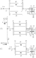
- FIGS. 4A to 4C are schematic views showing the operation of the electric prosthesis in the first embodiment.
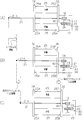
- FIGS. 9A to 9C are schematic views showing the operation of the electric prosthesis in the second embodiment.
- FIGS. (A)-(C) are schematic diagrams showing the operation of the electric prosthesis in the third embodiment.
- the electric prosthetic hand is a prosthetic hand body 11, a plurality of finger parts 12, 13, a wire 21 for each finger part 12, 13, a drive source, a lock mechanism A, and a drawing mechanism B for each finger part 12, 13. It has.
- the prosthetic hand body 11 is a portion corresponding to the back of a human hand, and forms a skeleton part of the electric prosthetic hand.
- Each finger part 12, 13 includes a plurality of movable parts 14 and a plurality of joint parts 15.
- the plurality of movable parts 14 are arranged so as to form a row along their own length direction.
- the side close to the prosthetic hand main body 11 of each finger part 12 and 13 is called a base end
- the side far from the prosthetic hand main body 11 is called a front end.
- One of the plurality of joint portions 15 is disposed between the prosthetic hand main body 11 and the movable portion 14 at a location closest to the prosthetic hand main body 11.
- the remaining joint portion 15 is disposed between the adjacent movable portions 14.
- Each movable portion 14 can be bent with the joint portion 15 in contact with the base end portion as a fulcrum.
- the pulley body 16 is provided for the finger parts 12 and 13 in the prosthetic hand body 11. Each pulley 16 is fixed to a common rotating shaft 18 orthogonal to the length direction of each finger portion 12, 13, and rotates integrally with the rotating shaft 18.
- the wire 21 for each of the finger parts 12 and 13 corresponds to a tendon of a human finger, and is arranged along the length direction of the finger parts 12 and 13 through the joint parts 15.
- the distal end portion 21 ⁇ / b> A of each wire 21 is locked to the distal end portion of the most movable portion 14.
- Each wire 21 is arranged via all the movable parts 14 and all the joint parts 15. The base end portion of each wire 21 is locked to the pulley 16.
- the drive source is for pulling the wire 21 in the right direction of FIG. 1, that is, in the bending direction to bend the finger parts 12 and 13.
- the motor 22 common to the finger parts 12 and 13 and the finger part 12 are used. , 13 and a polymer actuator 25 provided for each.
- an electric motor that rotationally drives the output shaft 23 by energization is used as the motor 22.
- the motor 22 is attached to the prosthetic hand body 11 so as not to move, and can be rotated forward and backward by switching the mode of energization.
- the output shaft 23 of the motor 22 extends in a direction perpendicular to the rotary shaft 18, that is, a direction perpendicular to the paper surface of FIG. 1, and is drivingly connected to the rotary shaft 18 via a worm gear mechanism 40. .
- the motor 22 rotates the pulleys 16 in the direction in which the wire 21 is wound by rotating the output shaft 23 in one direction. Further, the motor 22 can rotate the pulleys 16 in the direction in which the wire 21 is pulled out by rotating the output shaft 23 in the direction opposite to the above direction.
- Each polymer actuator 25 is for pulling the wire 21 in the bending direction after winding the wire 21 by the motor 22.
- the polymer actuator 25 is formed of a polymer material, elastically deforms in response to voltage application, and performs an expansion / contraction operation by restoring the original shape in response to the stop of voltage application.
- Each polymer actuator 25 includes a so-called dielectric system and an ion system.
- a dielectric polymer actuator 25 that is excellent in terms of displacement, generated force, and the like is employed.
- FIG. 2 shows the dielectric polymer actuator 25 in a state of being flattened.
- the polymer actuator 25 includes a dielectric layer 26 formed of an insulating insulating polymer material having elasticity, and a conductive polymer material having elasticity.
- a pair of electrodes 27 and 28 sandwiched from both sides in the thickness direction (vertical direction in FIG. 2) are provided.
- the dielectric layer 26 is formed of a polymer compound (polymer gel or the like) whose crosslink point moves, for example, polyrotaxane.
- both the electrodes 27 and 28 are made of general-purpose rubber or the like.
- the polymer actuator 25 expands the dielectric layer 26 along its surface in response to voltage application between the electrodes 27 and 28, and contracts the dielectric layer 26 in response to the cessation of voltage application.
- the expansion and contraction operation is performed by restoring to.
- the main part of the polymer actuator 25 is a cylindrical shape having both ends opened as shown in FIGS. 3A and 3B by winding the dielectric layer 26 and the electrodes 27 and 28 in a spiral shape. It is formed in a long shape. As described above, the polymer actuator 25 has a compact form and has good mountability on the electric prosthesis.
- Each polymer actuator 25 extends in the axial direction of the dielectric layer 26, that is, in the length direction of the polymer actuator 25 by applying a voltage between the electrodes 27 and 28 (see FIG. 3B). . Further, the polymer actuator 25 is restored in its original shape by contracting in the axial direction (length direction) by stopping the voltage application (see FIG. 3A). As described above, the polymer actuator 25 performs an expansion / contraction operation in the axial direction by applying and stopping the application of voltage.
- a cylindrical female screw member 29 is inserted into and fixed to both openings in the axial direction of the polymer actuator 25.
- a female screw is formed on the inner wall surface of each female screw member 29.
- each polymer actuator 25 a coil spring 31 is disposed between the female screw members 29 in a compressed state.
- Each coil spring 31 urges both female screw members 29 in directions away from each other (each left-right direction in FIGS. 3A and 3B).
- the biasing force of the coil spring 31 is transmitted to the polymer actuator 25 through both female screw members 29. Therefore, the polymer actuator 25 is biased to extend in the axial direction.
- Such a configuration is adopted because when the dielectric layer 26 is extended in the direction along the surface, the extension of the polymer actuator 25 in the axial direction is suppressed by suppressing the extension in the direction along the vortex as much as possible. This is to make the amount as large as possible.
- FIG. 4A a plurality of polymer actuators 25 having the above-described configuration are used.
- two polymer actuators 25 are shown for convenience, but the number is not limited.
- FIG. 1 only one polymer actuator 25 for each of the finger portions 12 and 13 is shown.
- the plurality of polymer actuators 25 are arranged in parallel with the axial direction aligned with the length direction of the extended finger portions 12 and 13. That is, the expansion / contraction direction of each polymer actuator 25 and the length direction of each extended finger part 12, 13 match.
- both end portions in the length direction are movable ends.
- electrode take-out portions 32 and 33 are provided at both ends of each polymer actuator 25.
- the left electrode extraction portion 32 is electrically connected to the first electrode of both electrodes 27, 28, and the right electrode extraction portion 33 is electrically connected to the second electrode of both electrodes 27, 28. .
- a pair of mounting portions 34 and 35 each having a plate shape are disposed on both sides of each polymer actuator 25 in the axial direction. Both attachment portions 34 and 35 are opposed to each other with the plurality of polymer actuators 25 interposed therebetween.
- the right mounting portion 35 of both the mounting portions 34 and 35 is connected to the positive pole of the power source 36, and the left mounting portion 34 is connected to the negative pole of the power source 36 via the switch 37.
- each polymer actuator 25 is fastened to the left mounting portion 34 by a fastening member 38 such as a bolt.
- a fastening member 38 such as a bolt.
- each polymer actuator 25 is fastened to the right mounting portion 35 by a fastening member 39.
- the right electrode extraction portion 33 is brought into pressure contact with the right attachment portion 35, and the first electrode of the electrodes 27 and 28 is electrically connected to the right attachment portion 35 via the right electrode extraction portion 33. ing.
- the plurality of polymer actuators 25 are arranged in the middle of the wire 21 in a posture parallel to the wire 21. Moreover, both attachment parts 34 and 35 are arrange
- the plurality of polymer actuators 25 and the attachment portions 34 and 35 are not fixed to the prosthetic hand body 11 and can be moved together with the wire 21 in the length direction of the wire 21.
- the motor 22 has a characteristic that the displacement is large but the output torque is small
- each polymer actuator 25 has a characteristic that the displacement is small but the output torque is large.
- the motor 21 pulls the wire 21 a lot.
- the fingers 12 and 13 are pressed against the object to be grasped (not shown) with a strong force to grasp the object to be grasped, the wire 21 is pulled in the bending direction by the polymer actuator 25 with a strong force.
- the characteristics of the motor 22 are supplemented by the polymer actuators 25. That is, the operation of bending or displacing the extending fingers 12 and 13 to the position approaching the object to be grasped is performed by the motor 22 and the objects to be grasped are grasped by the fingers 12 and 13. The operation is performed by each polymer actuator 25.
- the lock mechanism A is a mechanism for restricting relative movement of the wire 21 with the motor 22 after the wire 21 is wound by the motor 22.
- the lock mechanism A one that satisfies the following conditions is used.
- Condition 1 When the wire 21 is wound by the motor 22, the motor 22 is allowed to rotate in the winding direction.
- Condition 2 After the wire 21 is wound by the motor 22, the relative movement of the wire 21 with the motor 22 is restricted by restricting the rotation of the motor 22 in the direction opposite to the winding direction.
- a worm gear 40 including a worm 41 and a worm wheel 42 is used as the lock mechanism A that satisfies the above conditions 1 and 2.
- the rotating shaft 18 of the pulley 16 is orthogonal to the output shaft 23 of the motor 22.
- the worm 41 is formed of a cylindrical or drum-shaped screw-shaped gear, and is provided on the output shaft 23 of the motor 22 so as to be integrally rotatable.
- the worm wheel 42 is a helical gear, is provided on the rotary shaft 18 so as to be integrally rotatable, and is meshed with the worm 41.
- the worm gear mechanism 40 is generally used when transmitting rotation with a large reduction ratio between two axes (rotary shaft 18 and output shaft 23) that are arranged at right angles to each other but do not intersect.
- the worm gear mechanism 40 is characterized in that a large load is required to rotate the worm 41 from the worm wheel 42.
- the pull-out mechanism B extends the bent fingers 12 and 13 by pulling out the wire 21 wound around the pulley 16 by the motor 22 in a direction opposite to the direction in which the motor 22 pulls (bending direction). belongs to.
- Each drawer mechanism B includes a wire 45 for each of the finger portions 12 and 13 and a return spring 46 for each of the finger portions 12 and 13.
- the wire 45 for each finger part 12, 13 is arranged along the length direction of the finger part 12, 13 in a state of passing through each joint part 15.
- the distal end portion 45A of each wire 45 is locked to the distal end portion of the movable portion 14 on the most distal end side.
- the wires 45 are arranged in a state of passing through all the movable parts 14 and all the joint parts 15.
- the proximal end portion 45 ⁇ / b> B of the wire 21 is connected to the return spring 46.
- Each return spring 46 urges the wire 45 in the direction opposite to the direction in which the motor 22 pulls the wire 21 (bending direction), that is, in the direction in which the finger portions 12 and 13 are extended.
- the electric prosthesis of the first embodiment is configured as described above. Next, the operation of this electric prosthetic hand will be described.
- FIG. 1 and FIG. 4 (A) show a state immediately before the gripping object is gripped by the electric prosthetic hand. At this time, the winding amount of the wire 21 by the motor 22 is minimized. Energization to the motor 22 is stopped. The wire 21 is pulled in a direction opposite to the direction (bending direction) pulled by the motor 22 by the drawing mechanism B (the wire 45 and the return spring 46). Each finger part 12 and 13 is extended.
- the switch 37 is closed.
- a voltage is applied between the electrodes 27 and 28 (see FIG. 2) of each polymer actuator 25.
- One of the electrodes 27 and 28 has a positive charge, and the other has a negative charge.
- the lock mechanism A (worm gear mechanism 40) allows the output shaft 23 to rotate in the direction of winding the wire 21.
- the rotation is transmitted to the rotating shaft 18 via the worm gear mechanism 40 (worm 41 and worm wheel 42).
- the pulley 16 is rotated together with the rotating shaft 18, and the wire 21 is wound around the pulley 16.
- the wire 21 is pulled rightward along the length direction, that is, in the bending direction, and the wire 21 moves toward the motor 22.
- each polymer actuator 25 is fixed to the wire 21 via the attachment portions 34 and 35. From this, as shown in FIG. 4B, each polymer actuator 25 moves in the bending direction together with the wire 21 in a stretched state.
- the movement of the wire 21 is transmitted to each movable portion 14 of the finger portions 12 and 13 via each joint portion 15, and the finger portions 12 and 13 are bent with the joint portion 15 as a fulcrum.
- the motor 22 has a characteristic that the output torque is small although the displacement amount is large compared to the polymer actuator 25. For this reason, the wire 21 is pulled a lot, and the finger portions 12 and 13 are greatly bent or displaced. This displacement is performed until the plurality of finger parts 12 and 13 approach the grasped object.
- the wire 21 is further pulled in the bending direction by each polymer actuator 25 contracting in this way. This movement of the wire 21 is transmitted to each movable part 14 of each finger part 12 and 13 via each joint part 15, and the finger parts 12 and 13 are further bent with the joint part 15 as a fulcrum.
- each polymer actuator 25 has a characteristic that the output torque is large although the amount of displacement is smaller than that of the motor 22. Accordingly, the wire 21 is pulled with a strong force, the plurality of finger portions 12 and 13 are pressed against the grasped object with a strong force, and the grasped object is stably grasped.
- the wire 21 wound by the motor 22 and pulled in the bending direction with respect to the length direction by the polymer actuator 25 is, as described above, by the drawing mechanism B (the wire 45, the return spring 46), A pulling force acts in the direction opposite to the bending direction.
- the movement of the wire 21 in the above direction is restricted by the lock mechanism A (worm gear mechanism 40), and the object to be grasped continues to be grasped by the plurality of finger portions 12 and 13.
- the output shaft 23 of the motor 22 is rotated (reversely rotated) in the direction opposite to the rotation direction when the gripping object is gripped. This rotation weakens the force with which the motor 22 pulls the wire 21.
- Each wire 21 is pulled in a direction opposite to the direction in which the motor 22 is pulled (bending direction) by the wire 45 and the return spring 46.
- the fingers 12 and 13 are extended, the force for gripping the gripping object is weakened, and the fingers 12 and 13 are separated from the gripping object.
- the switch 37 is closed during a period from the start of the reverse rotation of the motor 22 to immediately before the gripping object is gripped again by the electric prosthesis.
- a voltage is applied, each polymer actuator 25 expands, and the electric prosthesis returns to the state shown in FIG.
- Wires 21 are arranged on a plurality of finger parts 12 and 13 that bend and extend with the joint part 15 as a fulcrum. By winding the wire 21 with the motor 22, the finger portions 12 and 13 are bent by pulling the wire 21 in the bending direction.
- a polymer actuator 25 is disposed in the middle of the wire 21.
- a lock mechanism A that restricts relative movement of the wire 21 with the motor 22 after the winding of the wire 21 by the motor 22 is provided. When the polymer actuator 25 is expanded and contracted while the relative movement is restricted by the lock mechanism A, the wire 21 is pulled in the bending direction (FIG. 1).
- the operation of bending or displacing the extended fingers 12 and 13 to a position approaching the object to be gripped is performed by the motor 22 and the objects to be gripped are gripped by the fingers 12 and 13.
- the operation to be performed can be performed by each polymer actuator 25.
- the object to be grasped can be stably grasped while taking advantage of the motor 22 that can largely bend or displace the finger parts 12 and 13.
- the wire 21 wound by the motor 22 and pulled in the bending direction by the polymer actuator 25 is subjected to a pulling mechanism B that pulls the wire 21 in a direction opposite to the bending direction.
- the gripping object can be continuously gripped by the plurality of finger parts 12 and 13.
- the polymer actuator 25 assists the motor 22, a smaller motor 22 can be used, and the weight can be reduced and the power consumption can be reduced.
- the worm gear mechanism 40 is used as the lock mechanism A, and when the wire 21 is wound by the motor 22, the motor 22 is allowed to rotate in the winding direction. On the other hand, after the wire 21 is wound by the motor 22, the winding is performed. By restricting the rotation of the motor 22 in the direction opposite to the direction, the relative movement of the wire 21 with the motor 22 is restricted.
- Each polymer actuator 25 is fixed to the wire 21 via the attachment portions 34 and 35.
- each polymer actuator 25 is extended by applying a voltage (FIGS. 4A and 4B).
- the polymer actuators 25 are contracted by stopping the voltage application (FIG. 4 ( C)).
- the stretched polymer actuators 25 are moved together with the wire 21 in the bending direction, and the plurality of finger parts 12 and 13 approach the grasped object. It can be greatly bent (displaced) to the position.
- each polymer actuator 25 is contracted in a state in which the relative movement of the wire 21 with the motor 22 is restricted, so that the object to be grasped is moved by the plurality of finger parts 12 and 13. It can be gripped strongly.
- the dielectric layer 26 made of an insulating insulating polymer material having elasticity, and the dielectric layer 26 made of an elastic conductive polymer material from both sides in the thickness direction.
- An electrode including a pair of electrodes 27 and 28 sandwiched therebetween is used (FIG. 2).
- the dielectric layer 26 is extended in the direction along the surface, and in response to the stop of the voltage application, the dielectric layer 26 is contracted in the direction along the surface to restore the original. The shape can be restored.
- a current flows until a predetermined amount of charge is accumulated in each of the electrodes 27 and 28.
- a current hardly flows when a predetermined amount of charge is accumulated, it is consumed for the operation (extension / contraction) of the polymer actuator 25. Less power is required.
- a battery with a small capacity can be used as the power source 36 (FIGS. 3A and 3B), and convenience is improved.
- the main part of the polymer actuator 25 is formed in a cylindrical shape by winding the dielectric layer 26 and the electrodes 27 and 28 in a spiral shape (FIGS. 3A and 3B).
- each polymer actuator 25 can have a compact form (cylindrical shape) and can be mounted on an electric prosthesis.
- each polymer actuator 25 can be extended in the axial direction (the length direction of each polymer actuator 25) in the direction along the surface of the dielectric layer 26 (FIG. 3B). . Further, each polymer actuator 25 can be contracted in the axial direction in accordance with the stop of the voltage application (FIG. 3A).
- a plurality of polymer actuators 25 are used, both end portions thereof are movable ends, and the respective movable ends are attached to the attachment portions 34 and 35 (FIG. 4A).
- the polymer actuator 25 used as one of the drive sources of the finger parts 12 and 13 is lighter than a drive source formed of metal, for example, a motor or an electromagnetic actuator. Therefore, the weight reduction of the entire electric prosthesis can be achieved.
- the polymer actuator 25 is used, only one motor 22 is required. As described above, the polymer actuator 25 itself is lightweight. Therefore, the weight of the electric prosthesis can be reduced. Further, the control circuit of the motor 22 can be simplified.
- the dielectric layer 26 of the polymer actuator 25 is formed of an insulating polymer material having elasticity, and the electrodes 27 and 28 are formed of a conductive polymer material having elasticity (FIG. 2).
- the polymer actuator 25 is expanded and contracted to absorb the force. can do.
- the finger parts 12 and 13 are constituted by a plurality of movable parts 14 and a plurality of joint parts 15, and wires 21 that are regarded as tendons are arranged on these finger parts 12 and 13. Then, the fingers 21 and 13 are bent by pulling the wire 21 by winding it with the motor 22.
- the fingers 12 and 13 can be bent in a shape along the shape of the object to be grasped to grasp the object to be grasped.
- the types of gripping objects that can be gripped increase.
- a wire 21 driven by a motor 22 and a polymer actuator 25 is connected to each of a plurality of fingers 12 and 13 each having a plurality of joints 15 via a plurality of joints 15. Arranged in the state.
- the plurality of finger parts 12 and 13 can be bent or displaced to a position approaching the grasped object. Thereafter, the object to be grasped can be grasped by the plurality of finger parts 12 and 13 by pulling the wire 21 by the polymer actuator 25.
- the effect of the above (1) such that the object to be grasped can be stably grasped while utilizing the advantage of the motor 22 capable of largely displacing each finger part 12, 13 can be obtained as still more effective.
- the wire 21 is fixed to the mounting portions 34 and 35. However, in the second embodiment, the wire 21 moves along the length direction of the wire 21 with respect to each polymer actuator 25. It is provided as possible. More specifically, as shown in FIG. 5 (A), the wire 21 is movable along its own length direction with respect to the space between the adjacent polymer actuators 25 and the attachment portions 34 and 35. Is inserted.
- the pulley 16 is attached to the output shaft 23 of the motor 22 so as to be integrally rotatable.
- each polymer actuator 25 the end portions 25A on the finger portions 12, 13 side in the axial direction are fixed ends.
- the end portion 25B on the motor 22 side in the axial direction is a movable end.
- the attachment portion 34 to which the fixed end 25A for each polymer actuator 25 is attached is fixed to the prosthetic hand main body 11 and is not movable with respect to the synonymous hand main body 11.
- the attachment portion 35 to which the movable end 25B for each polymer actuator 25 is attached is not fixed to the prosthetic hand body 11, and the length direction of the wire 21 with respect to the synthesizing hand body 11 (the axial direction of the polymer actuator 25). It is possible to move to.
- lock mechanism A a mechanism that satisfies the following conditions is used.
- Condition 4 After the winding of the wire 21 by the motor 22, the wire 21 is locked to the movable end 25B, thereby restricting relative movement of the wire 21 with each polymer actuator 25.
- a collet chuck 50 is used in place of the worm gear mechanism 40 as the lock mechanism A that satisfies the above conditions 3 and 4.
- the collet chuck 50 includes a collet 51, a chuck main body 52, and an actuator 53, and is provided in the vicinity of the movable mounting portion 35.
- the collet 51 is for gripping the wire 21 as a workpiece, and has an insertion hole for the wire 21 at the center.
- the collet 51 is provided with cuts extending radially from the insertion hole.
- a tapered surface is formed that decreases in diameter as it approaches the pulley 16.
- the chuck main body 52 has a cylindrical shape in which both end portions in the length direction of the wire 21 are opened, and is fixed to the attachment portion 35. Therefore, the chuck body 52 moves in the length direction of the wire 21 together with the movable end 25 ⁇ / b> B as the polymer actuator 25 expands and contracts. Inside the chuck body 52, a tapered surface is formed corresponding to the collet 51, and the diameter of the taper is reduced as the pulley 16 is approached.
- the actuator 53 is composed of an electromagnetic solenoid or the like, and is drivingly connected to the collet 51, and moves the collet 51 along the length direction of the wire 21. As the collet 51 is moved closer to the pulley 16 and enters the chuck body 52, a portion sandwiched between adjacent cuts in the collet 51 is elastically deformed toward the center, and the wire 21 is gripped. Thereby, the relative movement between the wire 21 and the movable end 25B of the polymer actuator 25 is restricted.
- each polymer actuator 25 is contracted by stopping the voltage application when the motor 22 winds the wire 21.
- Each of the polymer actuators 25 is stretched by voltage application in a state where the relative movement between the wire 21 and the movable end 25B of the polymer actuator 25 is restricted by the lock mechanism A after winding the wire 21 by the motor 22. Be made.
- FIG. 5 (A) shows a state immediately before the gripping object is gripped by the electric prosthetic hand. At this time, the winding amount of the wire 21 by the motor 22 is minimized. Energization to the motor 22 is stopped. The wire 21 is pulled in a direction opposite to the pulling direction (bending direction) by the motor 22 by the drawing mechanism B (the wire 45 and the return spring 46). Each finger part 12 and 13 is extended.
- the switch 37 is opened, and voltage application between the electrodes 27 and 28 (see FIG. 2) of the polymer actuator 25 is stopped.
- each polymer actuator 25 no electric charge is accumulated in both electrodes 27 and 28 due to discharge.
- Each polymer actuator 25 is contracted as shown in FIG. Due to this contraction, the movable end 25 ⁇ / b> B close to the motor 22 approaches the fixed end 25 ⁇ / b> A close to the finger portions 12 and 13.
- the locking mechanism A does not lock the wire 21 to the movable end 25B, and allows relative movement between the wire 21 and each polymer actuator 25. Therefore, the wire 21 can move in the length direction of the wire 21 with respect to the polymer actuator 25.
- the output shaft 23 of the motor 22 is rotated in one direction integrally with the pulley 16.
- the wire 21 is wound around the pulley 16, the wire 21 is pulled in the bending direction on the right side of FIG. 5A along the length direction, and the wire 21 moves in the bending direction.
- the movement of the wire 21 is transmitted to each movable part 14 of the finger parts 12 and 13 via each joint part 15.
- the plurality of finger portions 12 and 13 are largely bent or displaced using the joint portions 15 as fulcrums to a position approaching the grasped object.
- each polymer actuator 25 is extended in the axial direction (length direction). With this extension, the movable end 25B moves away from the fixed end 25A.
- the attachment portion 35 to which the movable end 25B is fixed also moves in the same direction together with the lock mechanism A that locks the wire 21 to the end portion 25B (movable end). Therefore, the wire 21 is further pulled in the bending direction with respect to the length direction.
- the movement of the wire 21 is transmitted to each movable part 14 of the finger parts 12 and 13 via each joint part 15, and the finger parts 12 and 13 are bent using each joint part 15 as a fulcrum.
- the plurality of finger parts 12 and 13 are pressed against the object to be grasped with a strong force, and the object to be grasped is stably grasped.
- the locking of the wire 21 by the lock mechanism A is released. With this release, the wire 21 can move with respect to each polymer actuator 25. Under this state, the motor 22 is rotated in the direction opposite to the rotation direction when the object to be grasped is grasped. This rotation weakens the force with which the motor 22 pulls the wire 21. The wire 21 is pulled in a direction opposite to the direction in which the motor 22 is pulled (bending direction) by the wire 45 and the return spring 46. As a result, the fingers 12 and 13 are extended, the force for gripping the gripping object is weakened, and the fingers 12 and 13 are separated from the gripping object.
- the switch 37 is opened during a period from the start of the reverse rotation of the motor 22 to just before the gripping object is gripped again by the electric prosthesis.
- each polymer actuator 25 contracts, and the electric prosthesis returns to the state shown in FIG.
- the same effects as the effects (1), (3), (4), (6) to (10) in the first embodiment can be obtained.
- the following effect (11) can be obtained instead of the effect (2).
- a plurality of polymer actuators 25 are used, and only one end portion 25B along the length direction is a movable end, but each movable end has a common attachment portion. Since it is attached to 35, the same effect as the above (5) can be obtained. This is the same in the third embodiment described later.
- the wire 21 is provided to each polymer actuator 25 so as to be movable along the length direction of the wire 21.
- an end 25A close to the fingers 12 and 13 in the axial direction is a fixed end
- an end 25B close to the motor 22 is a movable end.
- a collet chuck 50 is used as the locking mechanism A, and when the wire 21 is wound by the motor 22, the wire 21 is not locked to the end portion 25B (movable end), and the wire 21 is relative to each polymer actuator 25. Movement is allowed. On the other hand, after the winding of the wire 21 by the motor 22, the relative movement of the wire 21 with each polymer actuator 25 is restricted by locking the wire 21 to the end portion 25B (movable end).
- each polymer actuator 25 When winding the wire 21 by the motor 22, each polymer actuator 25 is contracted by stopping the voltage application (FIGS. 5A and 5B). In a state where the relative movement of the wire 21 with respect to each polymer actuator 25 is restricted by the lock mechanism A (the collet chuck 50), each polymer actuator 25 is extended by applying a voltage (FIG. 5 (C)).
- the plurality of finger portions 12, 13 can be greatly bent or displaced to a position approaching the grasped object.
- each polymer actuator 25 is extended while the wire 21 is locked to the end portion 25B (movable end) by the lock mechanism A (collet chuck 50).
- the object to be grasped can be strongly grasped by the plurality of finger parts 12 and 13.
- the voltage application to the polymer actuator 25 is stopped when the wire 21 is wound by the motor 22 and the voltage is applied after the wire 21 is wound, compared with the period in which the grasped object is grasped by the finger parts 12 and 13.
- the period during which the finger parts 12 and 13 are separated from the grasped object is long, there is an advantage that the power consumption can be reduced.
- the motor 22, the lock mechanism A, and the pulley 16 are disposed on the attachment portion 35 of the movable end 25B of each polymer actuator 25, so that the motor 22
- the main body 11 is configured to be movable along the length direction of the wire 21.
- the lock mechanism A is constituted by the worm gear mechanism 40 including the worm 41 and the worm wheel 42 as in the first embodiment. Unlike the second embodiment, the collet chuck 50 is not used.
- the lock mechanism A in the third embodiment has the same function as the lock mechanism A in the first embodiment.
- each polymer actuator 25 is stopped. By this stop, each polymer actuator 25 is contracted.
- a voltage is applied to each polymer actuator 25 in a state where the relative movement between the wire 21 and the motor 22 is restricted by the lock mechanism A. By applying this voltage, each polymer actuator 25 is extended, and the motor 22 is moved in the bending direction by the extension.
- FIG. 6 (A) shows a state immediately before the gripping object is gripped by the electric prosthetic hand. At this time, the winding amount of the wire 21 by the motor 22 is minimized. Energization to the motor 22 is stopped. The wire 21 is pulled in a direction opposite to the pulling direction (bending direction) by the motor 22 by the drawing mechanism B (the wire 45 and the return spring 46). Each finger part 12 and 13 is extended.
- the switch 37 is opened, and voltage application between the electrodes 27 and 28 (see FIG. 2) of the polymer actuator 25 is stopped.
- each polymer actuator 25 no electric charge is accumulated in both electrodes 27 and 28 due to discharge.
- Each polymer actuator 25 is contracted as shown in FIG. Due to this contraction, the movable end 25 ⁇ / b> B close to the motor 22 approaches the fixed end 25 ⁇ / b> A close to the finger portions 12 and 13.
- the wire 21 is not fixed to each polymer actuator 25 (attachment portions 34 and 35), and can move along the length direction of the wire 21 with respect to each polymer actuator 25 (attachment portions 34 and 35). It is. Further, the motor 22 can move along the length direction of the wire 21 with respect to the prosthetic hand body 11.
- the motor 22 is used as a drive source. At this time, the rotation of the output shaft 23 in the winding direction of the wire 21 is allowed by the lock mechanism A (worm gear mechanism 40).
- the movement of the wire 21 is transmitted to each movable part 14 of the finger parts 12 and 13 via each joint part 15.
- the plurality of finger portions 12 and 13 are largely bent or displaced using the joint portions 15 as fulcrums to a position approaching the grasped object.
- This extension is performed by moving the movable end 25B away from the fixed end 25A and approaching the motor 22.
- the attachment portion 35 to which the end portion 25B (movable end) is fixed also moves to the motor 22 side together with the lock mechanism A. Accordingly, the motor 22 is moved in the bending direction. Therefore, the wire 21 is further pulled in the bending direction.
- the movement of the wire 21 is transmitted to each movable part 14 of the finger parts 12 and 13 via each joint part 15, and the finger parts 12 and 13 are bent using each joint part 15 as a fulcrum.
- the plurality of finger parts 12 and 13 are pressed against the object to be grasped with a strong force, and the object to be grasped is stably grasped.
- the output shaft 23 of the motor 22 is rotated in a direction opposite to the rotation direction when gripping the gripping object. This rotation weakens the force with which the motor 22 pulls the wire 21.
- the wire 21 is pulled in a direction opposite to the direction in which the motor 22 is pulled by the drawing mechanism B (the wire 45 and the return spring 46).
- the fingers 12 and 13 are extended, the force for gripping the gripping object is weakened, and the fingers 12 and 13 are separated from the gripping object.
- the switch 37 is opened during a period from the start of reverse rotation of the motor 22 to immediately before the gripping object is gripped by the electric prosthesis.
- each polymer actuator 25 contracts, and the electric prosthesis returns to the state shown in FIG.
- the same effects as the effects (1), (3), (4), (6) to (10) of the first embodiment can be obtained.
- the following effect (12) can be obtained instead of the effect (2).
- the wire 21 is provided so as to be movable along the length direction of the wire 21 with respect to each polymer actuator 25.
- the motor 22 is provided to be movable along the length direction of the wire 21.
- an end portion 25A close to the finger portions 12 and 13 is a fixed end
- an end portion 25B close to the motor 22 is a movable end.
- a worm gear mechanism 40 is used as the lock mechanism A, and when the wire 21 is wound by the motor 22, the motor 22 is allowed to rotate in the winding direction, and after the winding of the wire 21 by the motor 22, the winding direction is changed. By restricting the rotation of the motor 22 in the reverse direction, the relative movement of the wire 21 with the motor 22 is restricted.
- each polymer actuator 25 is contracted by stopping the voltage application (FIGS. 6A and 6B).
- each polymer actuator 25 is expanded by applying a voltage, and the bending direction is expanded by the extension.
- the motor 22 is moved to (Fig. 6C).
- the plurality of finger portions 12, 13 can be greatly bent or displaced to a position approaching the grasped object.
- the polymer actuator 25 is extended in a state where the rotation of the motor 22 in the direction opposite to the winding direction is restricted by the lock mechanism A, whereby the wire 21 is The object to be grasped can be strongly grasped by the plurality of finger parts 12 and 13 by pulling in the bending direction.
- the said embodiment can also be implemented as a modification which changed this as follows.
- the electric prosthetic hand can be applied to those having three or more finger parts 12 and 13. As the number of the finger parts 12 and 13 increases, the object to be grasped can be grasped stably.
- the electric prosthetic hand can be applied to a case where the finger parts 12 and 13 have a different number of movable parts 14 and joint parts 15 from the first to third embodiments. As the number of the movable parts 14 and the joint parts 15 increases, the finger parts 12 and 13 can be bent along the shape of the object to be grasped, and more stable grasping is possible.
- the minimum value of the number of movable parts and joint parts in each finger part is “1”. Even in this case, the effect (1) described above can be obtained.
- the advantage of stably grasping the object to be grasped while taking advantage of the motor that can greatly displace the finger part is that when at least one of the plurality of finger parts has a plurality of joint parts. , Become bigger. This is because as the number of joint portions increases, the amount of wire tension required to bend the finger portions for each joint portion increases. In this case, a plurality of fingers can be bent or displaced to a position approaching the grasped object by pulling the wire many times with a motor. Thereafter, the object to be grasped can be grasped by a plurality of fingers by pulling the wire with the polymer actuator.
- polymer actuator 25-A the polymer actuator 25
- an ion system may be adopted instead of the dielectric system described above.
- An ion-type polymer actuator is composed of an assembly of an ion exchange resin and an electrode.
- a typical example of this type of polymer actuator is that an electrode formed of a noble metal such as gold or platinum is bonded to both surfaces of a fluorine-based ion exchange resin film by electroless plating.
- ions move inside the ion exchange resin, and for example, cations move to the cathode side. This movement of ions causes a difference in swelling between the front and back of the polymer actuator, and the polymer actuator is elastically deformed.
- the polymer actuator is restored to its original shape by the elastic restoring force.
- the polymer actuator is expanded and contracted by these elastic deformation and restoration.
- the number of polymer actuators 25 attached to the electric prosthesis may be changed, or the number of polymer actuators 25 to be applied with voltage may be changed by control or operation depending on the situation. Also good.
- the motor 22 may be provided for each of the finger portions 12 and 13.
- the motor 22, the lock mechanism A (worm gear mechanism 40), the pulley 16, etc. are separated from each polymer actuator 25 along the length direction of the wire 21 with respect to the artificial hand main body 11. It may be provided so as to be movable. In this case, the motor 22 and the like are disposed in the vicinity of the movable end 25 ⁇ / b> B and the attachment portion 35 of each polymer actuator 25. This is because the motor 22 and the like are moved by each of the extending polymer actuators 25.
- the worm gear mechanism is provided on the condition that the relative movement between one of the motor 22 and the polymer actuator 25 and the wire 21 can be restricted after the wire 21 is wound by the motor 22. 40 and the collet chuck 50 may be used to configure the lock mechanism A.
Landscapes
- Health & Medical Sciences (AREA)
- Transplantation (AREA)
- Engineering & Computer Science (AREA)
- Orthopedic Medicine & Surgery (AREA)
- Heart & Thoracic Surgery (AREA)
- Veterinary Medicine (AREA)
- Cardiology (AREA)
- Biomedical Technology (AREA)
- Oral & Maxillofacial Surgery (AREA)
- Vascular Medicine (AREA)
- Life Sciences & Earth Sciences (AREA)
- Animal Behavior & Ethology (AREA)
- General Health & Medical Sciences (AREA)
- Public Health (AREA)
- Mechanical Engineering (AREA)
- Robotics (AREA)
- Prostheses (AREA)
- Manipulator (AREA)
Abstract
指部(12,13)は、関節部(15)を支点として屈曲及び伸展する。ワイヤ(21)は、関節部(15)を経由した状態で指部(12,13)に沿って配置される。モータ(22)はワイヤ(21)を巻き取ることで、その屈曲方向へ引っ張って指部(12,13)を屈曲させる。ワイヤ(21)の途中に配置された高分子アクチュエータ(25)は、高分子材料により長尺状に形成され、電圧印加に応じて弾性変形するとともに、電圧印加の停止に応じて元の形状に復元することにより軸方向に沿って伸縮動作する。ロック機構(A)は、モータ(22)によるワイヤ(21)の巻取り後にワイヤ(21)のモータ(22)との相対移動を規制する。高分子アクチュエータ(25)は、ロック機構(A)により相対移動が規制されている状態で伸縮動作することで、ワイヤ(21)を屈曲方向へ引っ張る。
Description
本発明は、通電により作動する駆動源を用いて複数の指部を屈曲及び伸展させるようにした電動義手に関するものである。
義手として、通電により作動するモータを駆動源として用い、モータの回転を、駆動機構を介して複数の指部に伝達し、それらの指部を屈曲及び伸展させて、把持対象物を把持するようにした電動義手が種々開発されている(例えば、特許文献1参照)。このモータとしては、電動義手への搭載性の観点から小型のものが用いられる。
上述したようにモータを駆動源とした電動義手では、指部を大きく屈曲又は変位させて把持対象物を把持することができる。反面、小型のモータが発生するトルクは小さい。そのため、把持対象物を指部によって安定して把持することが難しい。
本発明は、このような実情に鑑みてなされたものであって、その目的は、指部を大きく変位させることのできるモータの利点を活かしつつ、把持対象物を安定して把持することのできる電動義手を提供することにある。
上記課題を解決する電動義手は、それぞれ関節部を支点として屈曲及び伸展する複数の指部と、前記関節部を経由した状態で前記各指部に沿って配置されたワイヤと、前記ワイヤを巻き取ることで、同ワイヤを、その長さ方向に沿い、屈曲方向へ引っ張って前記指部を屈曲させるモータと、高分子材料により長尺状に形成されて前記ワイヤの途中に配置され、電圧印加に応じて弾性変形するとともに、電圧印加の停止に応じて元の形状に復元することにより軸方向に伸縮動作する高分子アクチュエータと、前記モータによる前記ワイヤの巻取り後に、同モータ及び前記高分子アクチュエータの一方と前記ワイヤとの相対移動を規制するロック機構とを備え、前記高分子アクチュエータは、前記ロック機構により前記相対移動が規制された状態で伸縮動作することで、前記ワイヤを前記屈曲方向に沿って引っ張るものである。
上記の構成によれば、複数の指部を屈曲させて把持対象物を把持する場合には、モータ及び高分子アクチュエータが駆動源とされる。
モータの出力軸が回転させられてワイヤが巻き取られると、ワイヤが屈曲方向に沿って引っ張られる。ワイヤの動きが、関節部を経由して指部の各部に伝達され、その指部が関節部を支点として屈曲させられる。
これに対し、ワイヤの途中に配置された高分子アクチュエータは、電圧が印加されると弾性変形し、その電圧印加が停止されると元の形状に復元することで軸方向に沿って伸縮動作する。
モータによってワイヤが巻き取られた後には、そのモータ及び高分子アクチュエータの一方とワイヤとの相対移動がロック機構によって規制される。そして、高分子アクチュエータの上記伸縮動作は、ロック機構により相対移動が規制された状態で行なわれる。この伸縮動作により、ワイヤが上記屈曲方向へさらに引っ張られる。ワイヤの動きが、関節部を経由して指部の各部に伝達され、その指部が関節部を支点としてさらに屈曲させられる。
ここで、モータには、変位量が多いが出力トルクが小さいという特性があり、高分子アクチュエータには、変位量は少ないが出力トルクが大きいという特性がある。
そのため、指部を大きく屈曲または多く変位させる場合には、モータによってワイヤを屈曲方向へ多く引っ張ればよい。一方、強い力で指部を把持対象物に押付けて同把持対象物を把持する場合には、高分子アクチュエータによってワイヤを強い力で屈曲方向へ引っ張るればよい。それにより、モータの特性が高分子アクチュエータによって補われる。その結果、複数の指部を把持対象物に接近する位置まで屈曲または変位させる動作については、モータによって行なわせ、複数の指部によって把持対象物を把持する動作については、高分子アクチュエータによって行なわせる。こうすることで、指部を大きく変位させることのできるモータの利点を活かしつつ、把持対象物を安定して把持することが可能となる。
なお、モータによって巻き取られ、高分子アクチュエータによって屈曲方向に沿って引っ張られたワイヤに対し、屈曲方向とは反対方向へ引っ張る力が作用しても、ワイヤがその方向へ移動することはロック機構により規制される。その結果、把持対象物は複数の指部によって把持され続ける。
上記電動義手において、前記ロック機構は、前記モータによる前記ワイヤの巻取り時に、巻取り方向への前記モータの回転を許容する。一方、前記モータによる前記ワイヤの巻取り後には、巻取り方向とは逆方向への前記モータの回転を規制することで、前記ワイヤの前記モータとの相対移動を規制するものである。前記高分子アクチュエータは前記ワイヤに固定されており、前記モータによる前記ワイヤの巻取り時には伸長させられ、前記ロック機構により前記相対移動が規制された状態で収縮させられるものであることが好ましい。
上記の構成によれば、モータによるワイヤの巻取り時には、巻取り方向へのモータの回転がロック機構により許容される。この回転により、ワイヤが屈曲方向へ引っ張られ、同ワイヤがモータ側へ移動する。
このときには、ワイヤに固定された高分子アクチュエータが伸長させられる。そのため、伸長状態の高分子アクチュエータがワイヤと一緒に上記屈曲方向へ移動する。上記ワイヤの動きが、関節部を経由して指部の各部に伝達され、複数の指部が把持対象物に接近する位置まで関節部を支点として大きく屈曲または変位させられる。
モータによるワイヤの巻取り後には、巻取り方向とは逆方向へのモータの回転がロック機構により規制され、ワイヤのモータとの相対移動が規制される。この相対移動の規制下で高分子アクチュエータが収縮させられる。この収縮する高分子アクチュエータにより、ワイヤが長さ方向についての上記屈曲方向へさらに引っ張られる。ワイヤの動きが、関節部を経由して指部の各部に伝達され、その指部が関節部を支点としてさらに屈曲させられる。複数の指部が強い力で把持対象物に押し当てられ、その把持対象物が安定して把持される。
上記電動義手において、前記ワイヤは、前記高分子アクチュエータに対し、同ワイヤの長さ方向に沿って移動可能に設けられており、前記高分子アクチュエータは、前記軸方向についての前記指部に近い端部に固定端を備え、前記モータに近い端部に可動端を備えており、前記ロック機構は、前記モータによる前記ワイヤの巻取り時に、同ワイヤを前記可動端に係止せず、同ワイヤと前記高分子アクチュエータとの相対移動を許容する。一方、前記モータによる前記ワイヤの巻取り後に、前記ロック機構は、同ワイヤを前記可動端に係止することで、同ワイヤと前記高分子アクチュエータとの相対移動を規制するものであることが好ましい。前記高分子アクチュエータは、前記モータによる前記ワイヤの巻取り時には収縮させられ、前記ロック機構により前記相対移動が規制されている状態で伸長させられるものであることが好ましい。
上記の構成によれば、モータによるワイヤの巻取り時には、同ワイヤが屈曲方向へ引っ張られる。このときには、高分子アクチュエータが収縮させられ、その可動端(モータに近い端部)が固定端(指部に近い端部)に接近する。また、ロック機構はワイヤを上記可動端に係止しない。そのため、ワイヤの高分子アクチュエータとの相対移動が許容され、同ワイヤがモータ側へ移動する。このワイヤの動きが、関節部を経由して指部の各部に伝達され、複数の指部が把持対象物に接近する位置まで関節部を支点として大きく屈曲または変位させられる。
モータによるワイヤの巻取り後には、同ワイヤがロック機構により高分子アクチュエータの可動端に係止される。この係止により、ワイヤの高分子アクチュエータとの相対移動が規制される。この相対移動の規制下で高分子アクチュエータが伸長させられる。この伸長に伴い、高分子アクチュエータの可動端(モータに近い端部)が固定端(指部に近い端部)から遠ざかる。この高分子アクチュエータの可動端により、ワイヤが屈曲方向に沿ってさらに引っ張られる。ワイヤの動きが、関節部を経由して指部の各部に伝達され、その指部が関節部を支点としてさらに屈曲させられる。複数の指部が強い力で把持対象物に押し当てられ、その把持対象物が安定して把持される。
上記電動義手において、前記ワイヤは前記高分子アクチュエータに対し、同ワイヤの長さ方向に沿って移動可能に設けられ、前記モータは前記ワイヤの長さ方向に沿って移動可能に設けられており、前記高分子アクチュエータは、前記指部に近い端部を固定端とし、前記モータに近い端部を可動端として配置されていることが望ましい。前記ロック機構は、前記モータによる前記ワイヤの巻取り時には、巻取り方向への前記モータの回転を許容し、一方、前記モータによる前記ワイヤの巻取り後には、巻取り方向とは逆方向への前記モータの回転を規制することで、前記ワイヤの前記モータとの相対移動を規制するものであることが望ましい。前記高分子アクチュエータは、前記モータによる前記ワイヤの巻取り時には収縮させられ、前記ロック機構により前記相対移動が規制されている状態で伸長させられ、その伸長により、前記屈曲方向に沿って前記モータを移動させるものであることが好ましい。
上記の構成によれば、モータによるワイヤの巻取り時には、巻取り方向へのモータの回転がロック機構により許容される。この回転により、ワイヤが屈曲方向へ引っ張られ、同ワイヤがモータ側へ移動する。このときには、高分子アクチュエータが収縮させられ、その可動端が固定端に接近する。上記ワイヤの動きが、関節部を経由して指部の各部に伝達され、複数の指部が把持対象物に接近する位置まで関節部を支点として大きく屈曲または変位させられる。
モータによるワイヤの巻取り後には、巻取り方向とは逆方向へのモータの回転がロック機構により規制され、ワイヤのモータとの相対移動が規制される。この相対移動の規制下で高分子アクチュエータが伸長させられる。この伸長に伴い、高分子アクチュエータの可動端が固定端から遠ざかり、上記屈曲方向に沿ってワイヤが移動させられる。
そのため、ワイヤが屈曲方向に沿ってさらに引っ張られる。ワイヤの動きが、関節部を経由して指部の各部に伝達され、その指部が関節部を支点としてさらに屈曲させられる。複数の指部が強い力で把持対象物に押し当てられ、その把持対象物が安定して把持される。
上記電動義手において、前記高分子アクチュエータは、弾性を有する絶縁性高分子材料により形成された誘電体層と、弾性を有する導電性高分子材料により形成されて前記誘電体層を両側から挟む一対の電極とを備え、前記両電極間への電圧印加に応じ、前記誘電体層をその面に沿う方向へ伸長させ、前記電圧印加の停止に応じ、前記誘電体層を収縮させて元の形状に復元させることにより伸縮動作するものであることが好ましい。
上記の構成によれば、一対の電極間に電圧が印加されると、一方の電極がプラスの電荷を帯び、他方の電極がマイナスの電荷を帯びる。ここで、各電極に電荷が所定量蓄積されるまでは電流が流れるが、電荷が所定量蓄積されると電流はほとんど流れなくなる。そのため、高分子アクチュエータの伸縮動作のために消費される電力は少なくてすむ。
両電極が上記のように電荷を帯びると、プラスの電荷とマイナスの電荷とが互いに引きつけ合う力(クーロン力)が両電極に作用し、誘電体層が両電極によって両側から押圧される。誘電体層は弾性を有する絶縁性高分子材料によって形成されているため、上記のように両電極によって両側から押圧されると、自身の表面に沿う方向に伸長する。電極も弾性を有する導電性高分子材料によって形成されているため、上記誘電体層に追従して伸長する。
両電極間への電圧印加が停止されると、各電極に蓄積されていた電荷が放出される。この放電により、各電極が帯びている電荷が少なくなり、上記クーロン力が小さくなる。その結果、誘電体層は、自身の弾性復元力により、同誘電体層の表面に沿う方向に収縮する。弾性を有する電極もまた誘電体層に追従して収縮する。
上記電動義手において、前記高分子アクチュエータは、前記誘電体層及び前記両電極が渦巻き状に巻かれることにより円筒状に形成されており、前記両電極間への電圧印加に応じて軸方向に沿って伸長し、電圧印加の停止に応じて軸方向に沿って収縮して元の形状に復元するものであることが好ましい。
上記の構成によれば、高分子アクチュエータは、誘電体層及びその両側の電極が渦巻き状に巻かれることにより、コンパクトな円筒状の形態となり、電動義手への搭載性が向上する。
円筒状をなす高分子アクチュエータは、両電極間への電圧印加に応じ、誘電体層の表面に沿う方向のうち軸方向(高分子アクチュエータの軸方向)に沿って伸長する。高分子アクチュエータは、両電極間への上記電圧印加の停止に応じ、軸方向に沿って収縮して元の形状に復元する。
上記電動義手において、前記高分子アクチュエータは複数本用いられており、前記高分子アクチュエータ毎の可動端は、共通の取付け部に取付けられていることが好ましい。
上記の構成によれば、高分子アクチュエータが複数本用いられ、それらの可動端が共通の取付け部に取付けられることで、同取付け部に大きな力が加えられる。その結果、取付け部を通じて各指部に大きな力が伝達される。
上記電動義手において、前記複数の指部の少なくとも1つが複数の関節部を有している場合には、前記複数の関節部を有する指部には、前記モータ及び前記高分子アクチュエータにより駆動される前記ワイヤが、前記複数の関節部を経由した状態で配置されていることが好ましい。
ワイヤを引っ張って指部を屈曲させるタイプの電動義手では、その指部が有する関節部の数が多くなるに従い、指部を関節部毎に屈曲させるために必要なワイヤの引っ張り量が多くなる。従って、複数の関節部を有する指部をワイヤによって屈曲させる電動義手に、モータ及び高分子アクチュエータを組合わせてワイヤを屈曲方向に沿って引っ張る上記電動義手を適用することで、指部を大きく変位させることのできるモータの利点を活かしつつ、把持対象物を安定して把持するといった効果が、より一層有効なものとして得られる。
上記電動義手によれば、指部を大きく変位させることのできるモータの利点を活かしつつ、把持対象物を安定して把持することができる。
(第1実施形態)
以下、電動義手の第1実施形態について、図1~図4を参照して説明する。
以下、電動義手の第1実施形態について、図1~図4を参照して説明する。
図1に示すように、電動義手は義手本体11、複数の指部12,13、指部12,13毎のワイヤ21、駆動源、ロック機構A、及び指部12,13毎の引出し機構Bを備えている。
義手本体11は、人の手の甲に相当する箇所であり、電動義手の骨格部分をなしている。各指部12,13は、複数の可動部14及び複数の関節部15を備えている。複数の可動部14は、自身の長さ方向に沿って列をなすように配置されている。ここで、各指部12,13の義手本体11に近い側を基端といい、義手本体11から遠い側を先端という。複数の関節部15の1つは、義手本体11と、その義手本体11に最も近い箇所の可動部14との間に配置されている。残りの関節部15は、隣り合う可動部14の間に配置されている。各可動部14は、その基端部に接する関節部15を支点として屈曲可能である。
義手本体11には、指部12,13毎にプーリ16が設けられている。各プーリ16は、各指部12,13の長さ方向に直交する共通の回転軸18に固定されており、その回転軸18と一体に回転する。
指部12,13毎のワイヤ21は、人の指の腱に相当するものであり、各関節部15を経由した状態で指部12,13の長さ方向に沿って配置されている。各ワイヤ21の先端部21Aは、最も先端の可動部14の先端部に係止されている。各ワイヤ21は、全ての可動部14及び全ての関節部15を経由した状態で配置されている。各ワイヤ21の基端部は、上記プーリ16に係止されている。
駆動源は、上記ワイヤ21を、図1の右方即ち屈曲方向へ引っ張って、指部12,13を屈曲させるためのものであり、指部12,13に共通のモータ22と、指部12,13毎に設けられた高分子アクチュエータ25とからなる。
モータ22としては、通電により出力軸23を回転駆動する電動モータが用いられている。モータ22は、義手本体11に移動不能に取付けられており、通電の態様を切替えることで正逆回転が可能である。モータ22の出力軸23は上記回転軸18に対して直交する方向、すなわち、図1の紙面に直交する方向へ延びていて、同回転軸18に、ウォームギヤ機構40を介して駆動連結されている。モータ22は、出力軸23を一方向へ回転させることで、ワイヤ21を巻付ける方向へ両プーリ16を回転させる。また、モータ22は、出力軸23を上記方向とは逆方向へ回転させることで、ワイヤ21を引き出す方向へ両プーリ16を回転させることが可能である。
各高分子アクチュエータ25は、上記モータ22によるワイヤ21の巻取り後に、そのワイヤ21を上記屈曲方向へ引っ張るためのものである。高分子アクチュエータ25は、高分子材料により形成され、かつ電圧印加に応じて弾性変形し、電圧印加の停止に応じて元の形状に復元することにより、伸縮動作を行う。
各高分子アクチュエータ25としては、誘電方式と呼ばれるものと、イオン方式と呼ばれるものとがある。本実施形態では、変位、発生力等の点で優れる誘電方式の高分子アクチュエータ25が採用されている。
図2は、誘電方式の高分子アクチュエータ25を、平面状に展開させた状態で示している。図2に示すように、高分子アクチュエータ25は、弾性を有する絶縁性高分子材料によって形成された誘電体層26と、弾性を有する導電性高分子材料により形成されて、誘電体層26をその厚み方向(図2の上下方向)についての両側から挟む一対の電極27,28とを備えている。
誘電体層26は、架橋点の動く高分子化合物(高分子ゲル等)、例えばポリロタキサンによって形成されている。これに対し、両電極27,28は、汎用ゴム等によって形成されている。
高分子アクチュエータ25は、両電極27,28間への電圧印加に応じ、誘電体層26をその面に沿って伸長させ、電圧印加の停止に応じ、誘電体層26を収縮させて元の形状に復元させることにより、伸縮動作を行う。
高分子アクチュエータ25の主要部は、誘電体層26及び両電極27,28が、渦巻き状に巻かれることにより、図3(A),(B)に示すように、両端が開口された円筒状に形成されていて、長尺状をなしている。このように、高分子アクチュエータ25はコンパクトな形態を採っており、電動義手への搭載性のよいものとなっている。
また、各高分子アクチュエータ25は、両電極27,28間への電圧印加により、誘電体層26の軸方向、すなわち、高分子アクチュエータ25の長さ方向に伸長する(図3(B)参照)。また、高分子アクチュエータ25は、電圧印加の停止により、上記軸方向(長さ方向)に収縮して元の形状に復元する(図3(A)参照)。このように、高分子アクチュエータ25は、電圧の印加及び印加停止により軸方向に伸縮動作を行う。
上記高分子アクチュエータ25の軸方向についての両方の開口には、円筒状の雌ねじ部材29がそれぞれ挿入されて固定されている。各雌ねじ部材29の内壁面には雌ねじが形成されている。
各高分子アクチュエータ25内において、上記両雌ねじ部材29間にはコイルばね31が圧縮された状態で配置されている。各コイルばね31は、両雌ねじ部材29を、互いに遠ざける方向(図3(A),(B)の各左右方向)へ付勢している。このコイルばね31の付勢力は、両雌ねじ部材29を通じて高分子アクチュエータ25に伝わる。従って、高分子アクチュエータ25は、その軸方向に伸びるように付勢されていることになる。このような構成を採っているのは、誘電体層26を面に沿う方向へ伸長させる際に、渦に沿う方向へ伸長するのを極力抑えることにより、軸方向への高分子アクチュエータ25の変位量を可能な限り大きくするためである。
図4(A)に示すように、上記の構成を有する高分子アクチュエータ25は複数本用いられている。図4(A)~(C)では、便宜上、2本の高分子アクチュエータ25が図示されているが、この本数に限られない。また、上記図1では、指部12,13毎の高分子アクチュエータ25が1本のみ図示されている。複数本の上記高分子アクチュエータ25は、軸方向を、伸展した指部12,13の長さ方向に揃えた状態で並列に配置されている。すなわち、各高分子アクチュエータ25の伸縮方向と、伸展した各指部12,13の長さ方向とが合致している。これらの高分子アクチュエータ25では、その長さ方向についての両端部が可動端とされている。
図3(A),(B)に示すように、各高分子アクチュエータ25の両端部には電極取出し部32,33が設けられている。左電極取出し部32は、両電極27,28の内の第1電極に電気的に接続され、右電極取出し部33は両電極27,28の内の第2電極に電気的に接続されている。
各高分子アクチュエータ25の軸方向についての両側には、それぞれ板状をなす一対の取付け部34,35が配置されている。両取付け部34,35は、複数の上記高分子アクチュエータ25を挟んで相対向している。両取付け部34,35の内の右取付け部35は電源36のプラス極に接続され、左取付け部34はスイッチ37を介して電源36のマイナス極に接続されている。
各高分子アクチュエータ25の左端部25Aは、ボルト等の締結部材38により左取付け部34に締結されている。この締結部材38により、左電極取出し部32が左取付け部34に圧接され、電極27,28の内の第1電極が左電極取出し部32を介して左取付け部34に電気的に接続されている。
また、各高分子アクチュエータ25の右端部25Bは、締結部材39により右取付け部35に締結されている。この締結部材39により、右電極取出し部33が右取付け部35に圧接させられ、電極27,28の内の第1電極が右電極取出し部33を介して右取付け部35に電気的に接続されている。
図4(A)~(C)に示すように、上記複数の高分子アクチュエータ25は、上記ワイヤ21に対し平行となる姿勢で、同ワイヤ21の途中に配置されている。また、両取付け部34,35は、上記ワイヤ21に対し直交した状態で同ワイヤ21の途中に配置されている。そして、両取付け部34,35がワイヤ21に固定されている。
上記複数の高分子アクチュエータ25及び両取付け部34,35は、義手本体11に固定されておらず、ワイヤ21とともにそのワイヤ21の長さ方向へ移動可能である。
ここで、モータ22には、変位量が多いが出力トルクが小さいという特性があり、各高分子アクチュエータ25には、変位量は少ないが出力トルクが大きいという特性がある。
そこで、こうした特性の相違を利用し、伸展している指部12,13を大きく屈曲又は変位させる場合には、モータ22によってワイヤ21を多く引っ張る。一方、強い力で指部12,13を把持対象物(図示略)に押付けて同把持対象物を把持する場合には、各高分子アクチュエータ25によってワイヤ21を強い力で上記屈曲方向へ引っ張る。こうすることで、モータ22の特性を各高分子アクチュエータ25によって補うようにしている。すなわち、伸展している複数の指部12,13を把持対象物に接近する位置まで屈曲又は変位させる動作については、モータ22によって行なわせ、複数の指部12,13によって把持対象物を把持する動作については、各高分子アクチュエータ25によって行なわせるようにしている。
図1に示すように、ロック機構Aは、モータ22によるワイヤ21の巻取り後に、そのワイヤ21のモータ22との相対移動を規制するための機構である。ロック機構Aとしては、次の条件を満たすものが用いられている。
条件1:モータ22によるワイヤ21の巻取り時には、巻取り方向へのモータ22の回転を許容する。
条件2:モータ22によるワイヤ21の巻取り後には、巻取り方向とは逆方向へのモータ22の回転を規制することで、ワイヤ21のモータ22との相対移動を規制する。
上記の条件1及び条件2を満たすロック機構Aとして、ウォーム41及びウォームホイール42からなるウォームギヤ40が用いられている。
より詳しくは、プーリ16の回転軸18は、モータ22の出力軸23に対して直交している。ウォーム41は、円筒形や鼓形のねじ状の歯車からなり、モータ22の出力軸23上に一体回転可能に設けられている。ウォームホイール42は、はす歯歯車からなり、上記回転軸18上に一体回転可能に設けられており、上記ウォーム41に噛み合わされている。
ウォームギヤ機構40は一般に、互いに直角に配置されているが交わらない2軸(回転軸18、出力軸23)の間で大きな減速比の回転を伝達する場合に用いられる。ウォームギヤ機構40には、ウォームホイール42からウォーム41を回転させるためには大きな荷重が必要になるという特徴がある。
引出し機構Bは、上記モータ22によりプーリ16に巻き取られたワイヤ21を、モータ22が引っ張る方向(屈曲方向)とは逆方向へ引き出して、屈曲された各指部12,13を伸展させるためのものである。各引出し機構Bは、指部12,13毎のワイヤ45と、指部12,13毎の復帰ばね46とを備えている。
指部12,13毎のワイヤ45は、各関節部15を経由した状態で同指部12,13の長さ方向に沿って配置されている。各ワイヤ45の先端部45Aは、最も先端側の可動部14の先端部に係止されている。ワイヤ45は、全ての可動部14及び全ての関節部15を経由した状態で配置されている。ワイヤ21の基端部45Bは復帰ばね46に連結されている。各復帰ばね46は、モータ22がワイヤ21を引っ張る方向(屈曲方向)とは逆方向へ、すなわち、指部12,13を伸展させる方向へワイヤ45を付勢している。
そして、モータ22によるワイヤ21の巻取り時には、両電極27,28間へ電圧が印加されて各高分子アクチュエータ25が伸長させられる。また、ロック機構Aによりワイヤ21のモータ22との相対移動が規制されている状態では、両電極27,28間への電圧印加が停止されて、各高分子アクチュエータ25が収縮させられる。
上記のようにして第1実施形態の電動義手が構成されている。次に、この電動義手の作用について説明する。
図1及び図4(A)は、電動義手によって把持対象物を把持する直前の状態を示している。このときには、モータ22によるワイヤ21の巻取り量が最少となっている。モータ22への通電は停止されている。ワイヤ21は、引出し機構B(ワイヤ45及び復帰ばね46)により、モータ22によって引っ張る方向(屈曲方向)とは逆方向へ引っ張られている。各指部12,13は伸展している。
また、図3(B)に示すように、スイッチ37が閉じられている。各高分子アクチュエータ25の両電極27,28(図2参照)間に電圧が印加されている。電極27,28の一方がプラスの電荷を帯び、他方がマイナスの電荷を帯びている。
プラスの電荷とマイナスの電荷とが互いに引きつけ合う力(クーロン力)が両電極27,28に作用し、誘電体層26がその厚み方向についての両側から押圧されて、誘電体層26の表面に沿う方向に伸長している。電極27,28も弾性を有する導電性高分子材料によって形成されているため、上記誘電体層26に追従して伸長している。誘電体層26及び両電極27,28が渦巻き状に巻かれることにより円筒状に形成された各高分子アクチュエータ25は、誘電体層26の表面に沿う方向のうち軸方向(長さ方向)に伸長している。
上記の状態から、電動義手によって把持対象物(図示略)を把持する場合には、モータ22及び高分子アクチュエータ25が駆動源とされる。
モータ22が駆動源とされる際には、ワイヤ21を巻き取る方向への出力軸23の回転が、ロック機構A(ウォームギヤ機構40)によって許容される。モータ22の出力軸23が回転されると、その回転がウォームギヤ機構40(ウォーム41及びウォームホイール42)を介して回転軸18に伝達される。プーリ16が回転軸18とともに回転され、ワイヤ21がプーリ16に巻き取られる。ワイヤ21が長さ方向に沿って右方、即ち、屈曲方向へ引っ張られ、同ワイヤ21がモータ22へ向かって移動する。
ここで、各高分子アクチュエータ25は取付け部34,35を介してワイヤ21に固定されている。このことから、図4(B)に示すように各高分子アクチュエータ25は、伸長した状態でワイヤ21と一緒に上記屈曲方向へ移動する。
このワイヤ21の動きは、各関節部15を経由して指部12,13の各可動部14に伝達され、その指部12,13が関節部15を支点として屈曲させられる。
上述したように、モータ22には、高分子アクチュエータ25に比べ、変位量が多いが出力トルクが小さいという特性がある。このことから、ワイヤ21が多く引っ張られて、指部12,13が大きく屈曲又は変位させられる。この変位は、複数の指部12,13が把持対象物に接近するまで行なわれる。
指部12,13が上記の状態になるまでワイヤ21がモータ22によってプーリ16に巻取られた後には、モータ22に対する通電が停止される。この停止により、ワイヤ21を屈曲方向へ引っ張る力が消失する。一方、ワイヤ21に対しては引出し機構B(ワイヤ45、復帰ばね46)による力、すなわち、モータ22が引っ張る方向(屈曲方向)とは逆方向へ引っ張る力が作用している。しかし、このときには、巻取り方向とは逆方向へのモータ22の回転がロック機構A(ウォームギヤ機構40)によって規制され、ワイヤ21のモータ22との相対移動が規制される。すなわち、ウォームギヤ40には、ウォームホイール42側からウォーム41を回転させるために大きな荷重が必要になる。従って、ウォームギヤ40がロック機構Aとされることで、モータ22に対する通電を停止させても、ワイヤ21が、プーリ16から引き出されることがなく、モータ22により巻き取られた位置に保持される。
そして、上記のようにウォームギヤ機構40によりワイヤ21のモータ22との相対移動が規制されている状況下で、図3(A)に示すように、スイッチ37が開かれ、高分子アクチュエータ25の両電極27,28(図2参照)間への電圧印加が停止される。各高分子アクチュエータ25では、放電(電荷の放出)により、両電極27,28に電荷が蓄積されない。その結果、各高分子アクチュエータ25が図4(C)に示すように収縮する。
このように収縮する各高分子アクチュエータ25により、ワイヤ21が屈曲方向へさらに引っ張られる。ワイヤ21のこの動きが、各関節部15を経由して各指部12,13の各可動部14に伝達され、指部12,13が関節部15を支点としてさらに屈曲させられる。
上述したように、各高分子アクチュエータ25には、モータ22に比べ変位量は少ないが出力トルクが大きいという特性がある。このことから、ワイヤ21が強い力で引っ張られて、複数の指部12,13が強い力で把持対象物に押し当てられ、その把持対象物が安定して把持される。
なお、モータ22によって巻き取られ、高分子アクチュエータ25によって長さ方向についての屈曲方向へ引っ張られたワイヤ21に対しては、上述したように、引出し機構B(ワイヤ45、復帰ばね46)により、屈曲方向とは逆方向へ引っ張る力が作用する。しかし、ワイヤ21が上記方向へ移動することはロック機構A(ウォームギヤ機構40)によって規制され、把持対象物が複数の指部12,13によって把持され続ける。
上記把持対象物から指部12,13を離す場合には、モータ22の出力軸23が、把持対象物を把持する際の回転方向とは逆方向へ回転(逆回転)される。この回転により、モータ22がワイヤ21を引っ張る力が弱まる。各ワイヤ21は、ワイヤ45及び復帰ばね46により、上記モータ22が引っ張る方向(屈曲方向)とは逆方向へ引っ張られる。その結果、各指部12,13が伸展させられ、把持対象物を把持する力が弱まり、各指部12,13が把持対象物から離れる。
なお、上記スイッチ37は、モータ22の上記逆回転開始から、電動義手によって把持対象物を再び把持する直前までの期間に閉じられる。スイッチ37が閉じられることで電圧が印加され、各高分子アクチュエータ25が伸長し、電動義手が図4(A)に示す状態に復帰する。
以上詳述した第1実施形態によれば、次の効果が得られる。
(1)それぞれ関節部15を支点として屈曲及び伸展する複数の指部12,13にワイヤ21が配置されている。ワイヤ21をモータ22によって巻き取ることで、同ワイヤ21を屈曲方向へ引っ張って指部12,13が屈曲させられる。ワイヤ21の途中に高分子アクチュエータ25が配置されている。モータ22によるワイヤ21の巻取り後に、同ワイヤ21のモータ22との相対移動を規制するロック機構Aが設けられている。ロック機構Aにより相対移動が規制された状態で高分子アクチュエータ25を伸縮動作させることで、ワイヤ21が屈曲方向へ引っ張られる(図1)。
そのため、伸展している複数の指部12,13を把持対象物に接近する位置まで大きく屈曲または変位させる動作については、モータ22によって行なわせ、複数の指部12,13によって把持対象物を把持する動作については、各高分子アクチュエータ25によって行なわせることができる。その結果、指部12,13を大きく屈曲または変位させることのできるモータ22の利点を活かしつつ、把持対象物を安定して把持することができる。
また、モータ22によって巻き取られ、高分子アクチュエータ25によって屈曲方向へ引っ張られたワイヤ21に対しては、引出し機構Bにより、屈曲方向とは反対の方向に、ワイヤ21を引っ張る力が作用するが、把持対象物を複数の指部12,13によって把持し続けることができる。
さらに、高分子アクチュエータ25がモータ22を補助するため、そのモータ22としてより小型のものを用いることができ、軽量化及び消費電力の低減を図ることができる。
(2)ロック機構Aとしてウォームギヤ機構40を用い、モータ22によるワイヤ21の巻取り時には、巻取り方向へのモータ22の回転を許容する一方、モータ22によるワイヤ21の巻取り後には、巻取り方向とは逆方向へのモータ22の回転を規制することで、ワイヤ21のモータ22との相対移動を規制する。
取付け部34,35を介して、各高分子アクチュエータ25をワイヤ21に固定する。モータ22によるワイヤ21の巻取り時には、電圧印加により各高分子アクチュエータ25を伸長させる(図4(A),(B))。ロック機構A(ウォームギヤ機構40)により、ワイヤ21のモータ22との相対移動が規制されている状態では、電圧印加を停止することで各高分子アクチュエータ25を収縮させるようにしている(図4(C))。
そのため、モータ22によってワイヤ21をプーリ16に巻き取ることで、伸長状態の各高分子アクチュエータ25をワイヤ21と一緒に屈曲方向へ移動させ、複数の指部12,13を把持対象物に接近する位置まで大きく屈曲(変位)させることができる。
また、モータ22によるワイヤ21の巻取り後には、ワイヤ21のモータ22との相対移動を規制した状態で各高分子アクチュエータ25を収縮させることで、把持対象物を複数の指部12,13によって強く把持することができる。
また、モータ22によるワイヤ21の巻取り時には高分子アクチュエータ25に電力を印加し、ワイヤ21の巻取り後に電圧印加を停止するため、把持対象物から指部12,13を離している期間に比べ、把持対象物を指部12,13によって把持している期間が長い場合には、電力消費量を少なくすることができるメリットもある。
(3)高分子アクチュエータ25として、弾性を有する絶縁性高分子材料により形成された誘電体層26と、弾性を有する導電性高分子材料により形成されて誘電体層26を厚み方向についての両側から挟む一対の電極27,28とを備えるものを用いている(図2)。
そのため、両電極27,28間への電圧印加により、誘電体層26をその面に沿う方向へ伸長させ、電圧印加の停止に応じ、誘電体層26を上記面に沿う方向へ収縮させて元の形状に復元させることができる。
また、各電極27,28に電荷が所定量蓄積されるまでは電流が流れるが、電荷が所定量蓄積されると電流はほとんど流れなくなるため、高分子アクチュエータ25の作動(伸縮)のために消費される電力が少なくてすむ。その結果、電源36(図3(A),(B))として、容量の少ないバッテリを使用することができ、利便性が向上する。
(4)誘電体層26及び両電極27,28を渦巻き状に巻くことにより、高分子アクチュエータ25の主要部分を円筒状に形成している(図3(A),(B))。
そのため、各高分子アクチュエータ25をコンパクトな形態(円筒状)とし、電動義手への搭載性を向上させることができる。
また、電圧印加により、各高分子アクチュエータ25を、誘電体層26の表面に沿う方向のうち軸方向(各高分子アクチュエータ25の長さ方向)へ伸長させることができる(図3(B))。また、上記電圧印加の停止に応じ、各高分子アクチュエータ25を上記軸方向に収縮させることができる(図3(A))。
(5)高分子アクチュエータ25を複数本用い、それらの両端部を可動端とし、各可動端を取付け部34,35に取付けている(図4(A))。
そのため、高分子アクチュエータ25を1本のみ用いた場合に比べ、取付け部34,35を通じてワイヤ21に対し大きな力を伝達し、把持対象物を両指部12,13による大きな力で把持することができる。
(6)指部12,13の駆動源の1つとして用いている高分子アクチュエータ25は、金属によって形成された駆動源、例えば、モータや電磁アクチュエータよりも軽量である。そのため、電動義手全体の軽量化を図ることができる。
(7)複数の関節部を有する指部を屈曲させる場合、関節部毎にモータを配置することも考えられる。この場合、重量が増加したり、モータの制御回路が複雑になったりする等の問題がある。
この点に関し、第1実施形態では、高分子アクチュエータ25を用いているとはいえ、モータ22は1つで済ませている。前述したように、高分子アクチュエータ25自体は軽量である。そのため、電動義手を軽量化することができる。また、モータ22の制御回路を簡単にすることもできる。
(8)高分子アクチュエータ25の誘電体層26を、弾性を有する絶縁性高分子材料によって形成し、電極27,28を、弾性を有する導電性高分子材料によって形成している(図2)。
そのため、屈曲している指部12,13に対し、これらを伸展させて把持対象物から離間させようとする力が外部から加わっても、高分子アクチュエータ25を伸縮させることで、その力を吸収することができる。
(9)指部12,13を複数の可動部14と複数の関節部15とにより構成し、これらの指部12,13に、腱に見立てたワイヤ21を配置する。そして、ワイヤ21をモータ22で巻き取ることにより引っ張って、指部12,13を屈曲させるようにしている。
そのため、関節部が1つのものとは異なり、指部12,13を把持対象物の形状に沿った形に屈曲させて、同把持対象物を把持することができる。また、把持できる把持対象物の種類が増える。
(10)ワイヤを引っ張って指部を屈曲させるタイプの電動義手では、その指部が有する関節部の数が多くなるに従い、指部を関節部毎に屈曲させるために必要なワイヤの引っ張り量が多くなる。
この点、第1実施形態では、それぞれ複数の関節部15を有する複数の指部12,13の各々に、モータ22及び高分子アクチュエータ25により駆動されるワイヤ21を、複数の関節部15を経由した状態で配置している。
そのため、ワイヤ21をモータ22によって多く引っ張ることで、複数の指部12,13を把持対象物に接近する位置まで屈曲または変位させることができる。その後に、ワイヤ21を高分子アクチュエータ25によって引っ張ることで、複数の指部12,13によって把持対象物を把持することができる。各指部12,13を大きく変位させることのできるモータ22の利点を活かしつつ、把持対象物を安定して把持するといった上記(1)の効果を、より一層有効なものとして得ることができる。
(第2実施形態)
次に、電動義手の第2実施形態について、図1~図3及び図5を参照して、第1実施形態との相違点を中心に説明する。
次に、電動義手の第2実施形態について、図1~図3及び図5を参照して、第1実施形態との相違点を中心に説明する。
第1実施形態では、ワイヤ21が両取付け部34,35に固定されたが、第2実施形態では、ワイヤ21が、各高分子アクチュエータ25に対し、同ワイヤ21の長さ方向に沿って移動可能に設けられている。より詳しくは、図5(A)に示すように、ワイヤ21は、隣り合う高分子アクチュエータ25の間の空間と、両取付け部34,35とに対し、自身の長さ方向に沿って移動可能に挿通されている。
プーリ16は、モータ22の出力軸23に一体回転可能に取付けられている。
各高分子アクチュエータ25において、その軸方向についての指部12,13側の端部25Aは固定端とされている。各高分子アクチュエータ25において、その軸方向についてのモータ22側の端部25Bは可動端とされている。
また、高分子アクチュエータ25毎の固定端25Aが取付けられた取付け部34は義手本体11に固定されており、同義手本体11に対し移動不能である。高分子アクチュエータ25毎の可動端25Bが取付けられた取付け部35は、義手本体11には固定されておらず、同義手本体11に対しワイヤ21の長さ方向(高分子アクチュエータ25の軸方向)へ移動可能である。
ロック機構Aとしては、次の条件を満たすものが用いられている。
条件3:モータ22によるワイヤ21の巻取り時には、同ワイヤ21を可動端25Bに係止せず、同ワイヤ21の各高分子アクチュエータ25との相対移動を許容する。
条件4:モータ22によるワイヤ21の巻取り後には、同ワイヤ21を可動端25Bに係止することで、同ワイヤ21の各高分子アクチュエータ25との相対移動を規制する。
上記の条件3及び条件4を満たすロック機構Aとして、第2実施形態では、上記ウォームギヤ機構40に代えて、コレットチャック50が用いられている。コレットチャック50は、コレット51、チャック本体52及びアクチュエータ53を備えており、可動側の取付け部35の近傍に設けられている。
コレット51は、ワイヤ21をワークとして把持するためのものであり、中心部にワイヤ21の挿通孔を有している。コレット51には、挿通孔から放射状に延びる切込みが設けられている。コレット51の外周には、プーリ16に近づくに従い縮径するテーパ面が形成されている。
チャック本体52は、ワイヤ21の長さ方向についての両端部が開放された筒状をなしており、取付け部35に固定されている。そのため、チャック本体52は、高分子アクチュエータ25の伸縮動作に伴い可動端25Bと一緒に前記ワイヤ21の長さ方向へ移動する。チャック本体52の内部には、上記コレット51に対応して、プーリ16に近づくに従い縮径するテーパ面が形成されている。
アクチュエータ53は、電磁ソレノイド等からなり、上記コレット51に駆動連結されており、同コレット51をワイヤ21の長さ方向に沿って移動させる。コレット51がプーリ16に近づくように移動させられ、チャック本体52に入り込むに従い、コレット51において、隣り合う切込みによって挟まれた部分が、中心部に向けて弾性変形させられ、ワイヤ21を掴む。それにより、そのワイヤ21と高分子アクチュエータ25の可動端25Bとの相対移動が規制される。
さらに、各高分子アクチュエータ25は、上記モータ22によるワイヤ21の巻取り時に、電圧印加が停止されて収縮させられる。また、各高分子アクチュエータ25は、モータ22によるワイヤ21の巻取り後、ロック機構Aによりワイヤ21と高分子アクチュエータ25の可動端25Bとの相対移動が規制されている状態で、電圧印加により伸長させられる。
上記以外の構成は第1実施形態と同様である。そのため、第1実施形態と同様の要素については同一の符号を付すことで、重複する説明を省略する。
次に、第2実施形態の電動義手の作用について説明する。
図5(A)は、電動義手によって把持対象物を把持する直前の状態を示している。このときには、モータ22によるワイヤ21の巻取り量が最少となっている。モータ22への通電は停止されている。ワイヤ21が引出し機構B(ワイヤ45及び復帰ばね46)によって、モータ22による引っ張り方向(屈曲方向)とは逆方向へ引っ張られている。各指部12,13は伸展している。
また、スイッチ37が開かれて高分子アクチュエータ25の両電極27,28(図2参照)の間への電圧印加が停止されている。各高分子アクチュエータ25では、放電により、両電極27,28に電荷が蓄積されていない。各高分子アクチュエータ25は図5(A)に示すように収縮している。この収縮により、モータ22に近い可動端25Bが指部12,13に近い固定端25Aに接近している。さらに、ロック機構Aは、ワイヤ21を可動端25Bに係止しておらず、同ワイヤ21と各高分子アクチュエータ25との相対移動を許容している。そのため、ワイヤ21は高分子アクチュエータ25に対して同ワイヤ21の長さ方向へ移動可能である。
上記の状態から、電動義手によって把持対象物を把持する場合には、まず、モータ22の出力軸23がプーリ16と一体に一方向へ回転させられる。ワイヤ21が同プーリ16に巻き取られ、ワイヤ21が長さ方向に沿って図5(A)の右方の屈曲方向へ引っ張られ、ワイヤ21が同屈曲方向へ移動する。ワイヤ21の動きが、各関節部15を経由して指部12,13の各可動部14に伝達される。複数の指部12,13が、把持対象物に接近する位置まで各関節部15を支点として大きく屈曲または変位させられる。
指部12,13が上記の状態になるまでワイヤ21がモータ22によってプーリ16に巻取られた後には、図5(B)に示すように、モータ22への通電が停止される。この停止により、ワイヤ21を屈曲方向へ引っ張る力が消失する。しかし、モータ22によってワイヤ21が巻き取られた後には、図5(C)に示すように、ワイヤ21は、ロック機構A(コレットチャック50)により高分子アクチュエータ25の可動端25B(取付け部35)に係止される。この係止により、ワイヤ21と可動端25B(取付け部35)との相対移動が規制される。そのため、モータ22によってプーリ16に巻き取られたワイヤ21が、引出し機構Bによって引き出されることがない。それどころか、ワイヤ21と高分子アクチュエータ25との相対移動が規制された状態のもとで、上記スイッチ37が閉じられ(図3(B)参照)、各高分子アクチュエータ25の両電極27,28(図2参照)の間に電圧が印加される。
この電圧印加により、各高分子アクチュエータ25が軸方向(長さ方向)に伸長させられる。この伸長に伴い、可動端25Bが固定端25Aから遠ざかる。可動端25Bが固定された取付け部35も、ワイヤ21を端部25B(可動端)に係止しているロック機構Aと一緒に同方向へ移動する。そのため、ワイヤ21が長さ方向についての上記屈曲方向へさらに引っ張られる。
ワイヤ21の動きが、各関節部15を経由して指部12,13の各可動部14に伝達され、指部12,13が各関節部15を支点として屈曲させられる。複数の指部12,13が強い力で把持対象物に押し当てられ、その把持対象物が安定して把持される。
上記把持対象物から指部12,13を離す場合には、ロック機構Aによるワイヤ21の係止が解除される。この解除により、ワイヤ21は各高分子アクチュエータ25に対して移動することが可能となる。この状態のもと、モータ22が、把持対象物を把持する際の回転方向とは逆方向へ回転される。この回転により、モータ22がワイヤ21を引っ張る力が弱まる。ワイヤ21は、ワイヤ45及び復帰ばね46により、上記モータ22が引っ張る方向(屈曲方向)とは逆方向へ引っ張られる。その結果、各指部12,13が伸展させられ、把持対象物を把持する力が弱まり、各指部12,13が把持対象物から離れる。
なお、上記スイッチ37は、モータ22の上記逆回転開始から、電動義手によって把持対象物を再び把持する直前までの期間に開かれる。スイッチ37が開かれることで、各高分子アクチュエータ25が収縮し、電動義手は図5(A)に示す状態に復帰する。
従って、第2実施形態によれば、第1実施形態における効果(1),(3),(4),(6)~(10)と同様の効果が得られる。そのほか、効果(2)に代えて、次の(11)の効果が得られる。また、第2実施形態では、複数本の高分子アクチュエータ25が用いられ、それらの長さ方向に沿った一方の端部25Bのみが可動端とされているが、各可動端が共通の取付け部35に取付けられていることから、上記(5)と同様の効果が得られる。この点は、後述する第3実施形態でも同様である。
(11)第2実施形態によれば、ワイヤ21は、各高分子アクチュエータ25に対し、同ワイヤ21の長さ方向に沿って移動可能に設けられる。各高分子アクチュエータ25において、軸方向についての指部12,13に近い端部25Aが固定端であり、モータ22に近い端部25Bが可動端である。
ロック機構Aとしてコレットチャック50が用いられ、モータ22によるワイヤ21の巻取り時には、同ワイヤ21が端部25B(可動端)に係止されず、同ワイヤ21の各高分子アクチュエータ25との相対移動が許容される。一方、モータ22によるワイヤ21の巻取り後には、同ワイヤ21を端部25B(可動端)に係止することで、同ワイヤ21の各高分子アクチュエータ25との相対移動が規制される。
モータ22によるワイヤ21の巻取り時には、電圧印加の停止により各高分子アクチュエータ25が収縮さられる(図5(A),(B))。ロック機構A(コレットチャック50)により、ワイヤ21の各高分子アクチュエータ25との相対移動が規制されている状態では、電圧を印加することで各高分子アクチュエータ25を伸長させるようにしている(図5(C))。
そのため、モータ22によってワイヤ21をプーリ16に巻き取ることで、複数の指部12,13を把持対象物に接近する位置まで大きく屈曲または変位させることができる。
また、モータ22によるワイヤ21の巻取り後には、ロック機構A(コレットチャック50)によりワイヤ21が端部25B(可動端)に係止されている状態で各高分子アクチュエータ25を伸長させることで、把持対象物を複数の指部12,13によって強く把持することができる。
さらに、モータ22によるワイヤ21の巻取り時には高分子アクチュエータ25への電圧印加を停止し、ワイヤ21の巻取り後に電圧を印加するため、把持対象物を指部12,13によって把持する期間に比べ、把持対象物から指部12,13を離している期間が長い場合には、電力消費量を少なくすることができるというメリットもある。
(第3実施形態)
次に、電動義手の第3実施形態について、図1~図3及び図6を参照して、第2実施形態との相違点を中心に説明する。
次に、電動義手の第3実施形態について、図1~図3及び図6を参照して、第2実施形態との相違点を中心に説明する。
図6(A)に示すように、第3実施形態では、モータ22、ロック機構A、プーリ16が各高分子アクチュエータ25の可動端25Bの取付け部35に配置されることで、モータ22が義手本体11に対し、ワイヤ21の長さ方向に沿って移動可能に構成されている。
また、第3実施形態では、第1実施形態と同様、ウォーム41及びウォームホイール42からなるウォームギヤ機構40によってロック機構Aが構成されている。第2実施形態とは異なり、コレットチャック50は用いられていない。第3実施形態でのロック機構Aは、第1実施形態でのロック機構Aと同様の機能を担っている。
さらに、モータ22によるワイヤ21の巻取り時には、各高分子アクチュエータ25に対する電圧印加が停止される。この停止により、各高分子アクチュエータ25が収縮させられる。また、モータ22によるワイヤ21の巻取り後、ロック機構Aによりワイヤ21とモータ22との相対移動が規制された状態で、各高分子アクチュエータ25に対し、電圧が印加される。この電圧印加により、各高分子アクチュエータ25が伸長させられ、その伸長により、モータ22が屈曲方向へ移動させられる。
上記以外の構成は第2実施形態と同様である。そのため、第2実施形態と同様の要素については同一の符号を付すことで、重複する説明を省略する。
次に、第3実施形態の電動義手の作用について説明する。
図6(A)は、電動義手によって把持対象物を把持する直前の状態を示している。このときには、モータ22によるワイヤ21の巻取り量が最少となっている。モータ22への通電は停止されている。ワイヤ21が引出し機構B(ワイヤ45及び復帰ばね46)によって、モータ22による引っ張り方向(屈曲方向)とは逆方向へ引っ張られている。各指部12,13は伸展している。
また、スイッチ37が開かれて高分子アクチュエータ25の両電極27,28(図2参照)間への電圧印加が停止されている。各高分子アクチュエータ25では、放電により、両電極27,28に電荷が蓄積されていない。各高分子アクチュエータ25は図6(A)に示すように収縮している。この収縮により、モータ22に近い可動端25Bが指部12,13に近い固定端25Aに接近している。さらに、ワイヤ21は各高分子アクチュエータ25(取付け部34,35)に固定されておらず、各高分子アクチュエータ25(取付け部34,35)に対してワイヤ21の長さ方向に沿って移動可能である。また、モータ22は義手本体11に対してワイヤ21の長さ方向に沿って移動することが可能である。
上記の状態から、電動義手によって把持対象物を把持する場合には、まず、モータ22が駆動源とされる。この際、ワイヤ21を巻き取る方向への出力軸23の回転は、ロック機構A(ウォームギヤ機構40)によって許容される。
モータ22の出力軸23が回転されると、その回転がウォームギヤ機構40(ウォーム41及びウォームホイール42)を介して回転軸18に伝達される。プーリ16が回転軸18とともに一方向へ回転させられ、ワイヤ21がプーリ16に巻き取られる。ワイヤ21が長さ方向に沿って図6(A)の右方の屈曲方向へ引っ張られる。このときには、高分子アクチュエータ25は収縮され続ける。そのため、ワイヤ21は長さ方向に沿い、屈曲方向へ移動する。
ワイヤ21の動きは、各関節部15を経由して指部12,13の各可動部14に伝達される。複数の指部12,13が、把持対象物に接近する位置まで各関節部15を支点として大きく屈曲または変位させられる。
指部12,13が上記の状態になるまでワイヤ21がモータ22によってプーリ16に巻取られた後には、図6(B)に示すように、モータ22に対する通電が停止される。この停止により、ワイヤ21を屈曲方向へ引っ張る力が消失する。一方、ワイヤ21に対しては引出し機構B(ワイヤ45、復帰ばね46)による力、すなわち、モータ22が引っ張る方向(屈曲方向)とは逆方向へ引っ張る力が作用している。しかし、このときには、図6(C)に示すように、巻取り方向とは逆方向へのモータ22の回転がロック機構A(ウォームギヤ機構40)によって規制され、ワイヤ21のモータ22との相対移動が規制される。従って、モータ22に対する通電を停止させても、ワイヤ21が、プーリ16から引き出されることがなく、モータ22により巻き取られた位置に保持される。
そして、上記のようにウォームギヤ機構40により、ワイヤ21とモータ22との相対移動が規制されている状況下で、上記スイッチ37が閉じられ(図3(B)参照)、各高分子アクチュエータ25の両電極27,28(図2参照)間に電圧が印加される。この電圧印加により、各高分子アクチュエータ25が軸方向(長さ方向)に伸長させられる。
この伸長は、可動端25Bが固定端25Aから遠ざかり、かつ、モータ22に接近するように移動することにより行なわれる。端部25B(可動端)が固定された取付け部35も、ロック機構Aと一緒にモータ22側へ移動する。これに伴い、モータ22が屈曲方向へ移動させられる。そのため、ワイヤ21が屈曲方向へさらに引っ張られる。
ワイヤ21の動きが、各関節部15を経由して指部12,13の各可動部14に伝達され、指部12,13が各関節部15を支点として屈曲させられる。複数の指部12,13が強い力で把持対象物に押し当てられ、その把持対象物が安定して把持される。
上記把持対象物から指部12,13を離す場合には、モータ22の出力軸23が、上述した把持対象物を把持する際の回転方向とは逆方向へ回転される。この回転により、モータ22がワイヤ21を引っ張る力が弱まる。ワイヤ21は、引出し機構B(ワイヤ45、復帰ばね46)により、上記モータ22が引っ張る方向とは逆方向へ引っ張られる。その結果、各指部12,13が伸展させられ、把持対象物を把持する力が弱まり、各指部12,13が把持対象物から離れる。
なお、上記スイッチ37は、モータ22の逆回転の開始から、電動義手によって把持対象物を把持する直前までの期間に開かれる。スイッチ37が開かれることで、各高分子アクチュエータ25が収縮し、電動義手は図6(A)に示す状態に復帰する。
従って、第3実施形態によれば、第1実施形態の効果(1),(3),(4),(6)~(10)と同様の効果が得られる。そのほか、効果(2)に代えて次の(12)の効果が得られる。
(12)ワイヤ21は、各高分子アクチュエータ25に対し、同ワイヤ21の長さ方向に沿って移動可能に設けられる。モータ22はワイヤ21の長さ方向に沿って移動可能に設けられる。各高分子アクチュエータ25において、指部12,13に近い端部25Aを固定端とし、モータ22に近い端部25Bを可動端とする。
ロック機構Aとしてウォームギヤ機構40が用いられ、モータ22によるワイヤ21の巻取り時には、巻取り方向へのモータ22の回転を許容する一方、モータ22によるワイヤ21の巻取り後には、巻取り方向とは逆方向へのモータ22の回転を規制することで、ワイヤ21のモータ22との相対移動が規制される。
モータ22によるワイヤ21の巻取り時には、電圧印加の停止により各高分子アクチュエータ25が収縮させられる(図6(A),(B))。ロック機構A(ウォームギヤ40)により、ワイヤ21の各高分子アクチュエータ25との相対移動が規制されている状態では、電圧を印加することで各高分子アクチュエータ25を伸長させ、その伸長により、屈曲方向へモータ22を移動させるようにしている(図6(C))。
そのため、モータ22によってワイヤ21をプーリ16に巻き取ることで、複数の指部12,13を把持対象物に接近する位置まで大きく屈曲または変位させることができる。
また、モータ22によるワイヤ21の巻取り後には、巻取り方向とは逆方向へのモータ22の回転がロック機構Aによって規制されている状態で高分子アクチュエータ25を伸長させることで、ワイヤ21を屈曲方向へ引っ張って把持対象物を複数の指部12,13によって強く把持することができる。
さらに、モータ22によるワイヤ21の巻取り時には、高分子アクチュエータ25への電圧印加を停止し、ワイヤ21の巻取り後に電圧を印加するため、把持対象物を指部12,13によって把持する期間に比べ、把持対象物から指部12,13を離している期間が長い場合には、電力消費量を少なくすることができるというメリットもある。
なお、上記実施形態は、これを以下のように変更した変形例として実施することもできる。
指部12,13について
・前記電動義手は、指部12,13を3本以上有するものにも適用可能である。指部12,13の本数が多くなるに従い、把持対象物を安定して把持することが可能となる。
・前記電動義手は、指部12,13を3本以上有するものにも適用可能である。指部12,13の本数が多くなるに従い、把持対象物を安定して把持することが可能となる。
・前記電動義手は、指部12,13が、第1~第3実施形態とは異なる数の可動部14及び関節部15を有するものにも適用可能である。可動部14及び関節部15の数が多くなるに従い、指部12,13を把持対象物の形状に沿って屈曲させることができ、より安定した把持が可能となる。
なお、各指部における可動部及び関節部の数の最小値は「1」である。この場合でも、上述した(1)の効果を得ることができる。
ただし、指部を大きく変位させることのできるモータの利点を活かしつつ、把持対象物を安定して把持するといった効果は、複数の指部の少なくとも1つが複数の関節部を有している場合に、より大きなものとなる。関節部の数が多くなるに従い、指部を関節部毎に屈曲させるために必要なワイヤの引っ張り量が多くなるからである。この場合、ワイヤをモータによって多く引っ張ることで、複数の指部を把持対象物に接近する位置まで屈曲または変位させることができる。その後に、ワイヤを高分子アクチュエータによって引っ張ることで、複数の指部によって把持対象物を把持することができる。
高分子アクチュエータ25について
・高分子アクチュエータ25としては、上述した誘電方式に代え、イオン方式が採用されてもよい。
・高分子アクチュエータ25としては、上述した誘電方式に代え、イオン方式が採用されてもよい。
イオン方式の高分子アクチュエータは、イオン交換樹脂と電極との接合体からなる。このタイプの高分子アクチュエータとしては、フッ素系イオン交換樹脂膜の両面に、金、白金等の貴金属によって形成された電極を、無電解メッキにより接合したものが代表的である。この高分子アクチュエータでは、電極間に数ボルトの電圧が印加されることで、イオン交換樹脂の内部でイオンの移動が起こり、例えば、陽イオンが陰極側へ移動する。このイオンの移動により、高分子アクチュエータの表裏で膨潤に差が生じて、同高分子アクチュエータが弾性変形する。電圧印加が停止されると、弾性復元力により高分子アクチュエータは元の形状に復元する。これらの弾性変形及び復元により、高分子アクチュエータを伸縮動作させる。
指部12,13が把持対象物を把持する力について
・この力は、次の要素を調整することで変更可能である。
・この力は、次の要素を調整することで変更可能である。
(i)高分子アクチュエータ25毎の電極27,28に印加する電圧。この電圧が高くなるに従い、上記把持力が増大する。
(ii)高分子アクチュエータ25の直径。この直径が大きくなるに従い、上記把持力が増大する。
(iii)伸縮動作する高分子アクチュエータ25の本数。この本数が多くなるに従い、上記把持力が増大する。
この場合、電動義手に装着される高分子アクチュエータ25の本数が変更されてもよいし、電圧印加の対象となる高分子アクチュエータ25の本数が状況に応じて、制御により、又は操作により変更されてもよい。
モータ22について
・モータ22は、指部12,13毎に設けられてもよい。
・モータ22は、指部12,13毎に設けられてもよい。
・第3実施形態において、モータ22、ロック機構A(ウォームギヤ機構40)、プーリ16等は、各高分子アクチュエータ25から分離した状態で、義手本体11に対し、ワイヤ21の長さ方向に沿って移動可能に設けられてもよい。この場合には、モータ22等は、各高分子アクチュエータ25の可動端25B及び取付け部35の近傍に配置される。これは、伸長する各高分子アクチュエータ25によってモータ22等を移動させるためである。
ロック機構Aについて
・モータ22によるワイヤ21の巻取り後に、同モータ22及び高分子アクチュエータ25の一方と、ワイヤ21との相対移動を規制することができるものであることを条件に、上記ウォームギヤ機構40及びコレットチャック50とは異なるものによってロック機構Aを構成してもよい。
・モータ22によるワイヤ21の巻取り後に、同モータ22及び高分子アクチュエータ25の一方と、ワイヤ21との相対移動を規制することができるものであることを条件に、上記ウォームギヤ機構40及びコレットチャック50とは異なるものによってロック機構Aを構成してもよい。
12,13…指部、15…関節部、21…ワイヤ、22…モータ、25…高分子アクチュエータ、25A…端部(固定端)、25B…端部(可動端)、26…誘電体層、27,28…電極、35…取付け部、40…ウォームギヤ(ロック機構)、50…コレットチャック(ロック機構)、A…ロック機構。
Claims (8)
- それぞれ関節部を支点として屈曲及び伸展する複数の指部と、
前記関節部を経由した状態で前記各指部に沿って配置されたワイヤと、
前記ワイヤを巻き取ることで、同ワイヤを、その長さ方向に沿い、屈曲方向へ引っ張って前記指部を屈曲させるモータと、
高分子材料により長尺状に形成されて前記ワイヤの途中に配置され、電圧印加に応じて弾性変形するとともに、電圧印加の停止に応じて元の形状に復元することにより軸方向に沿って伸縮動作する高分子アクチュエータと、
前記モータによる前記ワイヤの巻取り後に、同モータ及び前記高分子アクチュエータの一方と前記ワイヤとの相対移動を規制するロック機構と
を備え、前記高分子アクチュエータは、前記ロック機構により前記相対移動が規制された状態で伸縮動作することで、前記ワイヤを前記屈曲方向へ引っ張るものであることを特徴とする電動義手。 - 前記ロック機構は、前記モータによる前記ワイヤの巻取り時に、巻取り方向への前記モータの回転を許容する一方、前記モータによる前記ワイヤの巻取り後に、巻取り方向とは逆方向への前記モータの回転を規制することで、前記ワイヤの前記モータとの相対移動を規制するものであり、
前記高分子アクチュエータは前記ワイヤに固定されており、前記モータによる前記ワイヤの巻取り時には伸長させられ、前記ロック機構により前記相対移動が規制された状態で収縮させられるものである請求項1に記載の電動義手。 - 前記ワイヤは、前記高分子アクチュエータに対し、同ワイヤの長さ方向に沿って移動可能に設けられており、
前記高分子アクチュエータは、前記軸方向についての前記指部に近い端部に固定端を備え、前記モータに近い端部に可動端を備え、
前記ロック機構は、前記モータによる前記ワイヤの巻取り時に、同ワイヤを前記可動端に係止せず、同ワイヤと前記高分子アクチュエータとの相対移動を許容する一方、前記モータによる前記ワイヤの巻取り後に、同ワイヤを前記可動端に係止することで、同ワイヤと前記高分子アクチュエータとの相対移動を規制するものであり、
前記高分子アクチュエータは、前記モータによる前記ワイヤの巻取り時に収縮させられ、前記ロック機構により前記相対移動が規制された状態で伸長させられるものである請求項1に記載の電動義手。 - 前記ワイヤは前記高分子アクチュエータに対し、同ワイヤの長さ方向に沿って移動可能に設けられ、前記モータは前記ワイヤの長さ方向に沿って移動可能に設けられており、
前記高分子アクチュエータは、軸方向についての前記指部に近い端部に固定端を備え、前記モータに近い端部に可動端を備え、
前記ロック機構は、前記モータによる前記ワイヤの巻取り時に、巻取り方向への前記モータの回転を許容する一方、前記モータによる前記ワイヤの巻取り後に、巻取り方向とは逆方向への前記モータの回転を規制することで、前記ワイヤの前記モータとの相対移動を規制するものであり、
前記高分子アクチュエータは、前記モータによる前記ワイヤの巻取り時に収縮させられ、前記ロック機構により前記相対移動が規制された状態で伸長させられ、その伸長により、前記屈曲方向へ前記モータを移動させるものである請求項1に記載の電動義手。 - 前記高分子アクチュエータは、弾性を有する絶縁性高分子材料により形成された誘電体層と、弾性を有する導電性高分子材料により形成されて前記誘電体層を両側から挟む一対の電極とを備え、前記両電極間への電圧印加に応じ、前記誘電体層をその表面に沿う方向へ伸長させ、前記電圧印加の停止に応じ、前記誘電体層を収縮させて元の形状に復元させることにより伸縮動作するものである請求項1~4のいずれか一項に記載の電動義手。
- 前記高分子アクチュエータは、前記誘電体層及び前記両電極が渦巻き状に巻かれることにより円筒状に形成されており、前記両電極間への電圧印加に応じ軸方向へ伸長し、電圧印加の停止に応じ軸方向へ収縮して元の形状に復元するものである請求項5に記載の電動義手。
- 前記高分子アクチュエータは複数本用いられており、
前記高分子アクチュエータ毎の可動端は、共通の取付け部に取付けられている請求項6に記載の電動義手。 - 前記複数の指部の少なくとも1つは複数の関節部を有しており、前記複数の関節部を有する指部には、前記モータ及び前記高分子アクチュエータにより駆動される前記ワイヤが、前記複数の関節部を経由した状態で配置されている請求項1~7のいずれか一項に記載の電動義手。
Priority Applications (2)
| Application Number | Priority Date | Filing Date | Title |
|---|---|---|---|
| US14/435,469 US9585771B2 (en) | 2012-11-07 | 2013-10-11 | Electrically driven artificial hand |
| CN201380056111.8A CN104768501B (zh) | 2012-11-07 | 2013-10-11 | 电驱动人造手 |
Applications Claiming Priority (2)
| Application Number | Priority Date | Filing Date | Title |
|---|---|---|---|
| JP2012-245461 | 2012-11-07 | ||
| JP2012245461A JP5928303B2 (ja) | 2012-11-07 | 2012-11-07 | 電動義手 |
Publications (1)
| Publication Number | Publication Date |
|---|---|
| WO2014073326A1 true WO2014073326A1 (ja) | 2014-05-15 |
Family
ID=50684440
Family Applications (1)
| Application Number | Title | Priority Date | Filing Date |
|---|---|---|---|
| PCT/JP2013/077762 Ceased WO2014073326A1 (ja) | 2012-11-07 | 2013-10-11 | 電動義手 |
Country Status (4)
| Country | Link |
|---|---|
| US (1) | US9585771B2 (ja) |
| JP (1) | JP5928303B2 (ja) |
| CN (1) | CN104768501B (ja) |
| WO (1) | WO2014073326A1 (ja) |
Cited By (3)
| Publication number | Priority date | Publication date | Assignee | Title |
|---|---|---|---|---|
| CN104161608A (zh) * | 2014-08-04 | 2014-11-26 | 中国科学院深圳先进技术研究院 | 一种腱传动假手 |
| CN105078628A (zh) * | 2015-09-06 | 2015-11-25 | 丹阳假肢厂有限公司 | 一种仿生手无名指、小拇指结构 |
| JP2017524545A (ja) * | 2014-06-05 | 2017-08-31 | メドロボティクス コーポレイション | アーティキュレーティングロボットプローブ、該プローブを組み込む方法及びシステム、及び、外科処置を実行する方法 |
Families Citing this family (18)
| Publication number | Priority date | Publication date | Assignee | Title |
|---|---|---|---|---|
| WO2015120083A1 (en) | 2014-02-04 | 2015-08-13 | Rehabilitation Institute Of Chicago | Modular and lightweight myoelectric prosthesis components and related methods |
| GB201403265D0 (en) | 2014-02-25 | 2014-04-09 | Touch Emas Ltd | Prosthetic digit for use with touchscreen devices |
| KR101679600B1 (ko) * | 2014-10-20 | 2016-11-28 | 금오공과대학교 산학협력단 | 로봇 핑거 |
| US9974667B1 (en) * | 2015-05-28 | 2018-05-22 | Blain Joseph Cazenave | Electromagnetic actuation mechanism for individual digit control of an artificial hand |
| JP6653557B2 (ja) * | 2015-11-30 | 2020-02-26 | 正毅 千葉 | 誘電エラストマー動作装置 |
| SE542072C2 (en) * | 2017-06-19 | 2020-02-18 | Tendo Ab | A device for pivoting a body member around a joint |
| US10973660B2 (en) | 2017-12-15 | 2021-04-13 | Touch Bionics Limited | Powered prosthetic thumb |
| IT201800005213A1 (it) * | 2018-05-09 | 2019-11-09 | Mano protesica sottoattuata | |
| KR102600256B1 (ko) * | 2018-06-08 | 2023-11-08 | 피에이치디, 인크. | 자율적 캡슐화 그리퍼 툴링 |
| JP2020032509A (ja) * | 2018-08-31 | 2020-03-05 | 豊田合成株式会社 | 関節装置 |
| EP4403142B1 (en) | 2019-04-10 | 2025-06-25 | Touch Bionics Limited | Prosthetic digit with articulating links |
| US11564815B2 (en) | 2019-09-17 | 2023-01-31 | Victoria Hand Project | Upper arm prosthetic apparatus and systems |
| WO2021053557A1 (en) | 2019-09-18 | 2021-03-25 | Touch Bionics Limited | Prosthetic digits and actuators |
| US11931270B2 (en) | 2019-11-15 | 2024-03-19 | Touch Bionics Limited | Prosthetic digit actuator |
| EP4061288A4 (en) * | 2019-11-19 | 2023-08-09 | President and Fellows of Harvard College | Device for assisting motion of a joint |
| KR102316229B1 (ko) * | 2020-02-12 | 2021-10-22 | (주)아스토 | 정전기적 부착력을 이용한 그리퍼, 이를 이용한 비정형 물체 피킹 방법 |
| US11957606B2 (en) | 2020-10-29 | 2024-04-16 | Victoria Hand Project | Low-cost prosthetic apparatus, methods, kits, and systems with improved force transfer elements |
| US20250144788A1 (en) * | 2022-02-10 | 2025-05-08 | Sarcomere Dynamics Inc. | Shape memory material actuator and hybrid actuator comprising same |
Citations (3)
| Publication number | Priority date | Publication date | Assignee | Title |
|---|---|---|---|---|
| JP2009083020A (ja) * | 2007-09-28 | 2009-04-23 | Hiroshima Pref Gov | 多指可動ロボットハンド及び多指可動ロボットハンドにおける指関節駆動制御方法 |
| JP2009124875A (ja) * | 2007-11-15 | 2009-06-04 | Toyoda Gosei Co Ltd | アクチュエータ |
| JP2011152620A (ja) * | 2010-01-28 | 2011-08-11 | Yaskawa Electric Corp | ロボットアーム駆動装置 |
Family Cites Families (3)
| Publication number | Priority date | Publication date | Assignee | Title |
|---|---|---|---|---|
| JP3893453B2 (ja) | 2002-04-16 | 2007-03-14 | 独立行政法人産業技術総合研究所 | 義手 |
| JP2006123149A (ja) * | 2004-11-01 | 2006-05-18 | Sharp Corp | 関節駆動機構およびロボットハンド |
| CN101919755B (zh) | 2010-07-25 | 2012-06-27 | 山东科技大学 | 一种关节牵拉式仿人形机器人手 |
-
2012
- 2012-11-07 JP JP2012245461A patent/JP5928303B2/ja not_active Expired - Fee Related
-
2013
- 2013-10-11 CN CN201380056111.8A patent/CN104768501B/zh not_active Expired - Fee Related
- 2013-10-11 US US14/435,469 patent/US9585771B2/en not_active Expired - Fee Related
- 2013-10-11 WO PCT/JP2013/077762 patent/WO2014073326A1/ja not_active Ceased
Patent Citations (3)
| Publication number | Priority date | Publication date | Assignee | Title |
|---|---|---|---|---|
| JP2009083020A (ja) * | 2007-09-28 | 2009-04-23 | Hiroshima Pref Gov | 多指可動ロボットハンド及び多指可動ロボットハンドにおける指関節駆動制御方法 |
| JP2009124875A (ja) * | 2007-11-15 | 2009-06-04 | Toyoda Gosei Co Ltd | アクチュエータ |
| JP2011152620A (ja) * | 2010-01-28 | 2011-08-11 | Yaskawa Electric Corp | ロボットアーム駆動装置 |
Cited By (3)
| Publication number | Priority date | Publication date | Assignee | Title |
|---|---|---|---|---|
| JP2017524545A (ja) * | 2014-06-05 | 2017-08-31 | メドロボティクス コーポレイション | アーティキュレーティングロボットプローブ、該プローブを組み込む方法及びシステム、及び、外科処置を実行する方法 |
| CN104161608A (zh) * | 2014-08-04 | 2014-11-26 | 中国科学院深圳先进技术研究院 | 一种腱传动假手 |
| CN105078628A (zh) * | 2015-09-06 | 2015-11-25 | 丹阳假肢厂有限公司 | 一种仿生手无名指、小拇指结构 |
Also Published As
| Publication number | Publication date |
|---|---|
| JP5928303B2 (ja) | 2016-06-01 |
| US9585771B2 (en) | 2017-03-07 |
| US20150297367A1 (en) | 2015-10-22 |
| CN104768501B (zh) | 2016-09-07 |
| JP2014094030A (ja) | 2014-05-22 |
| CN104768501A (zh) | 2015-07-08 |
Similar Documents
| Publication | Publication Date | Title |
|---|---|---|
| JP5928303B2 (ja) | 電動義手 | |
| JP5880106B2 (ja) | 高分子アクチュエータの取付構造 | |
| US9662197B2 (en) | Artificial muscle | |
| Jafari et al. | AwAS-II: A new actuator with adjustable stiffness based on the novel principle of adaptable pivot point and variable lever ratio | |
| US20080212262A1 (en) | Piezoelectric Ultracapacitor | |
| JP2013085579A (ja) | 電動義手 | |
| Jung et al. | Musclelike joint mechanism driven by dielectric elastomer actuator for robotic applications | |
| CN108127658B (zh) | 一种电磁力驱动的人工肌肉 | |
| Bazaev et al. | Electrically-induced twist in geometrically incompatible dielectric elastomer tubes | |
| Sun et al. | Electro-adhesive tubular clutch for variable-stiffness robots | |
| WO2009084305A1 (ja) | アクチュエータアレイおよびアクチュエータアレイの駆動方法 | |
| JPWO1999030877A1 (ja) | マイクロアクチュエータ | |
| JP6418484B2 (ja) | インダクタンス変更機構 | |
| CN104320015A (zh) | 仿生多自由度精密压电驱动装置 | |
| CN104753393B (zh) | 含曲梁结构的双压电堆步进旋转式作动器及方法 | |
| EP2053670B1 (en) | An elongated actuator structure | |
| JP2009159664A (ja) | 電場応答性高分子を用いた発電装置 | |
| Cho et al. | Super stretchable soft actuator made of twisted and coiled spandex fiber | |
| US20090058223A1 (en) | Piezoelectric Ultracapacitor | |
| JP2010207985A (ja) | 関節型駆動機構 | |
| WO2018163854A1 (ja) | 誘電エラストマー発電システム | |
| JP2018143720A (ja) | 多節環状弾性体 | |
| Naficy et al. | Bio-inspired polymer artificial muscles | |
| CN213859302U (zh) | 机械手 | |
| JP5243932B2 (ja) | 電歪アクチュエータシステム |
Legal Events
| Date | Code | Title | Description |
|---|---|---|---|
| 121 | Ep: the epo has been informed by wipo that ep was designated in this application |
Ref document number: 13852679 Country of ref document: EP Kind code of ref document: A1 |
|
| WWE | Wipo information: entry into national phase |
Ref document number: 14435469 Country of ref document: US |
|
| NENP | Non-entry into the national phase |
Ref country code: DE |
|
| 122 | Ep: pct application non-entry in european phase |
Ref document number: 13852679 Country of ref document: EP Kind code of ref document: A1 |