WO2014069294A1 - ガスホルダーシール材及びガスホルダーのシール構造 - Google Patents
ガスホルダーシール材及びガスホルダーのシール構造 Download PDFInfo
- Publication number
- WO2014069294A1 WO2014069294A1 PCT/JP2013/078662 JP2013078662W WO2014069294A1 WO 2014069294 A1 WO2014069294 A1 WO 2014069294A1 JP 2013078662 W JP2013078662 W JP 2013078662W WO 2014069294 A1 WO2014069294 A1 WO 2014069294A1
- Authority
- WO
- WIPO (PCT)
- Prior art keywords
- tank
- gas holder
- side end
- buffer member
- covered
- Prior art date
- Legal status (The legal status is an assumption and is not a legal conclusion. Google has not performed a legal analysis and makes no representation as to the accuracy of the status listed.)
- Ceased
Links
Images






Classifications
-
- F—MECHANICAL ENGINEERING; LIGHTING; HEATING; WEAPONS; BLASTING
- F17—STORING OR DISTRIBUTING GASES OR LIQUIDS
- F17B—GAS-HOLDERS OF VARIABLE CAPACITY
- F17B1/00—Gas-holders of variable capacity
- F17B1/24—Gas-holders of variable capacity of dry type
- F17B1/26—Gas-holders of variable capacity of dry type with flexible walls, e.g. bellows
-
- F—MECHANICAL ENGINEERING; LIGHTING; HEATING; WEAPONS; BLASTING
- F16—ENGINEERING ELEMENTS AND UNITS; GENERAL MEASURES FOR PRODUCING AND MAINTAINING EFFECTIVE FUNCTIONING OF MACHINES OR INSTALLATIONS; THERMAL INSULATION IN GENERAL
- F16J—PISTONS; CYLINDERS; SEALINGS
- F16J15/00—Sealings
- F16J15/50—Sealings between relatively-movable members, by means of a sealing without relatively-moving surfaces, e.g. fluid-tight sealings for transmitting motion through a wall
- F16J15/52—Sealings between relatively-movable members, by means of a sealing without relatively-moving surfaces, e.g. fluid-tight sealings for transmitting motion through a wall by means of sealing bellows or diaphragms
-
- F—MECHANICAL ENGINEERING; LIGHTING; HEATING; WEAPONS; BLASTING
- F17—STORING OR DISTRIBUTING GASES OR LIQUIDS
- F17C—VESSELS FOR CONTAINING OR STORING COMPRESSED, LIQUEFIED OR SOLIDIFIED GASES; FIXED-CAPACITY GAS-HOLDERS; FILLING VESSELS WITH, OR DISCHARGING FROM VESSELS, COMPRESSED, LIQUEFIED, OR SOLIDIFIED GASES
- F17C1/00—Pressure vessels, e.g. gas cylinder, gas tank, replaceable cartridge
-
- F—MECHANICAL ENGINEERING; LIGHTING; HEATING; WEAPONS; BLASTING
- F17—STORING OR DISTRIBUTING GASES OR LIQUIDS
- F17C—VESSELS FOR CONTAINING OR STORING COMPRESSED, LIQUEFIED OR SOLIDIFIED GASES; FIXED-CAPACITY GAS-HOLDERS; FILLING VESSELS WITH, OR DISCHARGING FROM VESSELS, COMPRESSED, LIQUEFIED, OR SOLIDIFIED GASES
- F17C2201/00—Vessel construction, in particular geometry, arrangement or size
- F17C2201/01—Shape
- F17C2201/0176—Shape variable
-
- F—MECHANICAL ENGINEERING; LIGHTING; HEATING; WEAPONS; BLASTING
- F17—STORING OR DISTRIBUTING GASES OR LIQUIDS
- F17C—VESSELS FOR CONTAINING OR STORING COMPRESSED, LIQUEFIED OR SOLIDIFIED GASES; FIXED-CAPACITY GAS-HOLDERS; FILLING VESSELS WITH, OR DISCHARGING FROM VESSELS, COMPRESSED, LIQUEFIED, OR SOLIDIFIED GASES
- F17C2201/00—Vessel construction, in particular geometry, arrangement or size
- F17C2201/03—Orientation
- F17C2201/032—Orientation with substantially vertical main axis
-
- F—MECHANICAL ENGINEERING; LIGHTING; HEATING; WEAPONS; BLASTING
- F17—STORING OR DISTRIBUTING GASES OR LIQUIDS
- F17C—VESSELS FOR CONTAINING OR STORING COMPRESSED, LIQUEFIED OR SOLIDIFIED GASES; FIXED-CAPACITY GAS-HOLDERS; FILLING VESSELS WITH, OR DISCHARGING FROM VESSELS, COMPRESSED, LIQUEFIED, OR SOLIDIFIED GASES
- F17C2201/00—Vessel construction, in particular geometry, arrangement or size
- F17C2201/05—Size
- F17C2201/052—Size large (>1000 m3)
-
- F—MECHANICAL ENGINEERING; LIGHTING; HEATING; WEAPONS; BLASTING
- F17—STORING OR DISTRIBUTING GASES OR LIQUIDS
- F17C—VESSELS FOR CONTAINING OR STORING COMPRESSED, LIQUEFIED OR SOLIDIFIED GASES; FIXED-CAPACITY GAS-HOLDERS; FILLING VESSELS WITH, OR DISCHARGING FROM VESSELS, COMPRESSED, LIQUEFIED, OR SOLIDIFIED GASES
- F17C2201/00—Vessel construction, in particular geometry, arrangement or size
- F17C2201/05—Size
- F17C2201/054—Size medium (>1 m3)
-
- F—MECHANICAL ENGINEERING; LIGHTING; HEATING; WEAPONS; BLASTING
- F17—STORING OR DISTRIBUTING GASES OR LIQUIDS
- F17C—VESSELS FOR CONTAINING OR STORING COMPRESSED, LIQUEFIED OR SOLIDIFIED GASES; FIXED-CAPACITY GAS-HOLDERS; FILLING VESSELS WITH, OR DISCHARGING FROM VESSELS, COMPRESSED, LIQUEFIED, OR SOLIDIFIED GASES
- F17C2223/00—Handled fluid before transfer, i.e. state of fluid when stored in the vessel or before transfer from the vessel
- F17C2223/01—Handled fluid before transfer, i.e. state of fluid when stored in the vessel or before transfer from the vessel characterised by the phase
- F17C2223/0107—Single phase
- F17C2223/0123—Single phase gaseous, e.g. CNG, GNC
-
- F—MECHANICAL ENGINEERING; LIGHTING; HEATING; WEAPONS; BLASTING
- F17—STORING OR DISTRIBUTING GASES OR LIQUIDS
- F17C—VESSELS FOR CONTAINING OR STORING COMPRESSED, LIQUEFIED OR SOLIDIFIED GASES; FIXED-CAPACITY GAS-HOLDERS; FILLING VESSELS WITH, OR DISCHARGING FROM VESSELS, COMPRESSED, LIQUEFIED, OR SOLIDIFIED GASES
- F17C2223/00—Handled fluid before transfer, i.e. state of fluid when stored in the vessel or before transfer from the vessel
- F17C2223/03—Handled fluid before transfer, i.e. state of fluid when stored in the vessel or before transfer from the vessel characterised by the pressure level
- F17C2223/033—Small pressure, e.g. for liquefied gas
-
- F—MECHANICAL ENGINEERING; LIGHTING; HEATING; WEAPONS; BLASTING
- F17—STORING OR DISTRIBUTING GASES OR LIQUIDS
- F17C—VESSELS FOR CONTAINING OR STORING COMPRESSED, LIQUEFIED OR SOLIDIFIED GASES; FIXED-CAPACITY GAS-HOLDERS; FILLING VESSELS WITH, OR DISCHARGING FROM VESSELS, COMPRESSED, LIQUEFIED, OR SOLIDIFIED GASES
- F17C2270/00—Applications
- F17C2270/01—Applications for fluid transport or storage
- F17C2270/0134—Applications for fluid transport or storage placed above the ground
Definitions
- the present invention relates to a gas holder sealing material and a gas holder sealing structure, and more specifically, a gas holder sealing material capable of maintaining excellent airtightness while improving the bending resistance of cold regions at low temperatures, and
- the present invention relates to a gas holder seal structure.
- Wiggins gas holders are known as devices for collecting and storing gas.
- a gas holder includes a tank for storing gas, a movable lid that moves up and down in the tank, a buffer member that moves up and down in the tank in conjunction with the movable lid, between the tank and the buffer member, and Cylindrical sealing material that connects between the buffer member and the movable lid is provided.
- This sealing material is formed of chloroprene rubber, acrylonitrile butadiene rubber, or the like (see, for example, Patent Documents 1 and 2).
- the sealing material interposed between the tank and the buffer member has one end fixed to the inner peripheral surface of the tank and the other end fixed to the outer edge of the buffer member. Therefore, the vicinity of one end (tank side end) and the other end (buffer member side end) of the sealing material is always in a bent state, and the bent state changes as the movable lid and the buffer member move up and down. To do. Therefore, the sealing material is required to have bending resistance in addition to excellent airtightness that prevents leakage of stored gas.
- the sealing material when the gas holder is disposed in a cold region, the sealing material may be cooled to near the embrittlement temperature of the rubber.
- the tank-side end portion of the sealing material is easy to transmit the low temperature of the outside air through the tank wall surface.
- the sealing material is formed of chloroprene rubber or acrylonitrile butadiene rubber, it has poor cold resistance, and therefore there is a problem that cracks are likely to occur at low temperatures in cold regions even if cracks do not occur at the bent portions at room temperature.
- the sealing material is made of rubber other than chloroprene rubber or acrylonitrile butadiene rubber, the durability (gas resistance) against methane gas or the like is inferior, so that there is a problem that the essential function as the sealing material is hindered.
- An object of the present invention is to provide a gas holder seal material and a gas holder seal structure capable of maintaining excellent airtightness while improving the bending resistance of a cold region under a low temperature.
- the gas holder sealing material of the present invention includes an inner peripheral surface of a tank constituting the gas holder, and a movable lid that moves up and down in the tank.
- a gas holder sealing material formed in a cylindrical shape interposed between an outer edge of a buffer member that moves up and down, a tank side end that is a side fixed to the inner peripheral surface of the tank, and an outer edge of the buffer member
- At least the tank side end of the buffer member side end to be fixed to the part, both surfaces of the end are covered with ethylene propylene diene rubber, and the tank side end and the buffer member side end
- the other parts are characterized in that ethylene propylene diene rubber is uncoated.
- the seal structure of the gas holder of the present invention includes an inner peripheral surface of a tank constituting the gas holder and an outer edge of a buffer member that moves up and down in the tank on the outer peripheral side of the movable lid in conjunction with the movable lid that moves up and down in the tank.
- the tank side end of the gas holder sealing material is fixed by protruding from the inner peripheral surface of the tank A tank-side fixing member; and a buffer-member-side fixing member that is provided on an outer edge of the buffer member and fixes the buffer-member-side end of the gas holder seal material, the tank-side end and the buffer-member-side end At least the tank side end of the part is covered with ethylene propylene diene rubber on both sides of the end, and with respect to parts other than the tank side end and the buffer member side end
- the surface of the portion of the gas holder seal material that is not covered with ethylene propylene diene rubber has an inner peripheral surface of the tank and the tank regardless of the vertical position of the buffer member.
- the configuration is such that the side fixing member is not contacted.
- Another gas holder seal structure includes a buffer member that moves up and down in the tank on the outer peripheral side of the movable lid in conjunction with an inner circumferential surface of the tank constituting the gas holder and a movable lid that moves up and down in the tank.
- a gas holder sealing structure having a cylindrical gas holder sealing material that seals between an outer edge portion, and the gas holder protruding from the inner peripheral surface of the tank and between the inner peripheral surface of the tank
- a tank-side fixing member that fixes the sealing material across the tank-side end portion, and a buffer-member-side fixing member that is provided on an outer edge portion of the buffer member and fixes the buffer member-side end portion of the gas holder sealing material.
- the surface of the tank side end facing the inner peripheral surface of the tank is covered with ethylene propylene diene rubber, and the surface of the tank side fixing member facing the tank side end is ethylene propylene. Characterized in that it is covered by Njiengomu.
- the gas holder seal material of the present invention (hereinafter referred to as a seal material) has at least both of the tank side end portion and the buffer member side end portion with respect to at least the tank side end portion.
- the tank side end that is covered with diene rubber (hereinafter referred to as EPDM) and that is not covered with EPDM for the parts other than the tank side end part and the buffer member side end part, so that the low temperature of the outside air is most easily transmitted
- EPDM having excellent cold resistance comes into contact with the inner peripheral surface of the tank. This improves the bending resistance of the tank side end portion at a low temperature.
- the EPDM intervenes, it becomes difficult for the low temperature of the outside air to be conducted to other portions, so that the bending resistance at a low temperature as the whole sealing material is improved. Accordingly, even when the gas holder is disposed in a cold region, it is possible to prevent a problem that a crack is generated in the sealing material at a low temperature. Further, since only the end portion of the sealing material is covered with EPDM, any material having excellent durability (gas resistance) against the gas stored in the tank can be selected for the main body portion of the sealing material. Therefore, it can be satisfactorily maintained without impairing the essential function (air tightness) as the sealing material.
- the coating length of EPDM can be made different between one side of the end covered with EPDM and the other side. As a result, it is possible to avoid a sudden change in the bending rigidity at the boundary between the part covered with EPDM on both sides and the part not covered with EPDM. This eliminates excessive stress concentration and is advantageous for improving the bending resistance. Moreover, since EPDM is used only for a necessary part (length), the amount of EPDM used can be minimized and material cost can be suppressed.
- the coating thickness of EPDM can be made different between one surface at the end covered with EPDM and the other surface. As a result, the coating thickness of the EPDM can be reduced to the minimum necessary on each surface, and an increase in the bending rigidity of the end portion coated with the EPDM can be suppressed. This is advantageous for improving the bending resistance. In addition, material costs can be reduced by minimizing the amount of EPDM used.
- the coating thickness of EPDM is set to 1.2 mm to 1.4 mm, for example. Thereby, bending resistance can be improved, suppressing effectively that the low temperature of external air is transmitted to the main-body part of a sealing material.
- the gas holder seal structure of the present invention includes the tank side fixing member and the buffer member side fixing member, and at least the tank side end portion and the buffer member side end portion with respect to the tank side end portion, Both surfaces of the end portion are covered with EPDM, and the portions other than the tank side end portion and the buffer member side end portion are configured so that EPDM is not covered, and the surface of the portion not covered with EPDM of the sealing material is Regardless of the vertical position of the buffer member, it does not come into contact with the inner peripheral surface of the tank and the tank side fixing member, so that the low temperature of outside air is not easily conducted to the portion of the seal material that is not covered with EPDM, and the low temperature of the entire seal material Bending resistance can be improved.
- EPDM comes into contact with the inner peripheral surface of the tank, it is possible to improve the bending resistance of the tank side end portion at a low temperature. Therefore, even when the gas holder is disposed in a cold region, it is possible to prevent a problem that a crack occurs in the sealing material at a low temperature.
- both surfaces of the buffer member side end are covered with EPDM, and the surface of the portion not covered with EPDM of the sealing material does not contact the buffer member regardless of the vertical position of the buffer member.
- This improves the resistance to bending at low temperatures at the end of the buffer member that is easy to transmit the low temperature of the outside air, such as the end on the tank side, and further improves the resistance to bending as a whole of the sealing material at low temperatures. . Therefore, it becomes more advantageous to prevent the occurrence of cracks at low temperatures.
- another gas holder sealing structure of the present invention includes a tank side fixing member and a buffer member side fixing member, and a surface of the tank side end facing the inner peripheral surface of the tank is covered with EPDM. Since the surface facing the tank side end of the tank side fixing member is covered with EPDM, the low temperature of the outside air is hardly conducted to the part of the sealing material that is not covered with EPDM. The bending resistance can be improved. Further, since the sealing material itself does not come into contact with the inner peripheral surface of the tank and the tank side fixing member at the tank side end portion, it is possible to improve the bending resistance of the tank side end portion at a low temperature.
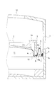
- FIG. 1 is a cross-sectional view showing a main part of a gas holder (in a state not filled with gas) in which the gas holder sealing material of the present invention is used.
- FIG. 2 is a cross-sectional view showing a main part of a gas holder (a state where gas is filled to about 1/3 of the maximum capacity) in which the gas holder sealing material of the present invention is used.
- FIG. 3 is a cross-sectional view showing a main part of a gas holder (a state where gas is filled to about 2/3 of the maximum capacity) in which the gas holder sealing material of the present invention is used.
- FIG. 1 is a cross-sectional view showing a main part of a gas holder (in a state not filled with gas) in which the gas holder sealing material of the present invention is used.
- FIG. 2 is a cross-sectional view showing a main part of a gas holder (a state where gas is filled to about 1/3 of the maximum capacity) in which the gas holder sealing material of the
- FIG. 4 is a cross-sectional view showing a main part of a gas holder (a state where gas is filled up to the maximum capacity) in which the gas holder sealing material of the present invention is used.
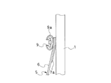
- FIG. 5 is an enlarged cross-sectional view of the tank side end of the gas holder seal material of FIG. 6 is an enlarged cross-sectional view of the tank side end of the gas holder seal material of FIG.
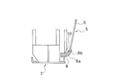
- FIG. 7 is an enlarged cross-sectional view of the buffer member side end of the gas holder seal material of FIG.
- FIG. 8 is an enlarged cross-sectional view of the buffer member side end of the gas holder seal material of FIG.
- FIG. 9 is an enlarged cross-sectional view showing a tank side end portion (a state where gas is not filled) of a gas holder seal material of another embodiment of the seal structure of the present invention.
- FIG. 10 is an enlarged cross-sectional view of a tank side end portion (a state filled with gas) of a gas holder seal material of another embodiment of the seal structure of the present invention.
- the gas holder includes a cylindrical tank 1 for storing gas, a circular movable lid 2 in a plan view that moves up and down in the tank 1, and interlocked with the movable lid 2. And a cylindrical buffer member 3 that moves up and down in the tank 1 on the outer peripheral side of the movable lid 2. Furthermore, a cylindrical sealing material 4 for connecting the movable lid 2 and the buffer member 3 and a cylindrical sealing material 5 for connecting the buffer member 3 and the tank 1 are provided.
- the sealing material of the present invention is a cylindrical sealing material 5 interposed between the inner peripheral surface of the tank 1 and the outer edge portion of the buffer member 3.
- a protrusion 2a that protrudes toward the upper side of the tank is provided on the periphery of the movable lid 2.
- a flange 3 a that protrudes toward the center of the tank is provided at the upper end of the cylindrical buffer member 3. The protrusion 2a of the movable lid 2 comes into contact with the flange 3a of the buffer member 3 when the movable lid 2 rises.
- the cylindrical seal material 4 has one end in the axial direction attached to the peripheral edge of the movable lid 2 and the other end attached to the lower end of the buffer member 3.
- the sealing material 5 of the present invention has one axial end attached to the lower end of the buffer member 3 and the other end attached to the inner peripheral surface of the tank 1.
- the sealing material 5 of the present invention is composed of a main body portion 6 serving as a base portion of the sealing material 5 and covering portions 7a, 7b, 8a, 8b provided on both sides of the end portion of the main body portion 6.
- the main body 6 has a structure in which a base fabric made of a fiber material is covered with a rubber material.
- a rubber material that covers the base fabric a material that does not easily permeate the stored gas and does not easily deteriorate due to contact with the stored gas is used depending on the stored gas.
- the gas to be stored is methane gas, chloroprene rubber or acrylonitrile butadiene rubber can be used.
- the thickness of the main-body part 6 is about 3 mm, for example.
- the covering portions 7a, 7b, 8a, 8b are all made of EPDM.
- the covering portions 7 a and 7 b are provided on the tank side end portion 7 which is the side fixed to the inner peripheral surface of the tank 1.
- the covering portions 8 a and 8 b are provided on the buffer member side end portion 8 which is a side fixed to the outer edge portion of the buffer member 3.
- These covering portions 7 a, 7 b, 8 a, 8 b can be covered by, for example, vulcanizing and bonding a sheet made of EPDM to the main body portion 6 of the sealing material 5.
- the covering portions 7a and 7b can be covered by fixing the sheet made of EPDM together with the main body portion 6 of the sealing material 5 by bolting when the sealing material 5 is fixed to the inner peripheral surface of the tank 1. .
- seat which consists of EPDM can also be made into cloth in order to raise intensity
- the covering portions 8a and 8b disposed at the buffer member side end portion 8 of the sealing material 5 are not necessarily provided, and at least the tank side end portion that most easily transmits the low temperature of the outside air 7 is provided with covering portions 7a and 7b.
- the seal structure of the present invention has the sealing material 5 described above. Specifically, as illustrated in FIGS. 5 to 8, a tank side fixing member 9 protruding from the inner peripheral surface of the tank 1 and a buffer member side fixing member 10 provided at the outer edge of the buffer member 3 are provided. I have. Further, at least the tank side end 7 of the tank side end 7 and the buffer member side end 8 is covered with EPDM on both sides of the end, and other than the tank side end 7 and the buffer member side end 8 EPDM is uncovered for the portion of this portion, and the surface of the portion not covered with EPDM of the sealing material 5 is the inner peripheral surface of the tank 1 and the tank side fixing member regardless of the vertical position of the buffer member 3. 9 is configured not to contact 9.
- the EPDM having excellent cold resistance contacts the inner peripheral surface of the tank 1 at the tank side end portion 7.
- the EPDM contacts the tank side fixing member 9.
- the tank side end 7 does not directly contact a member that is easily influenced by outside air, the bending resistance of the tank side end 7 at a low temperature is improved.
- the presence of EPDM makes it difficult for the low temperature of the outside air to be conducted to the main body 6 that is not covered with EPDM, so that the bending resistance of the sealing material 1 as a whole at low temperatures is also improved.
- a ⁇ -shaped clamp is used as shown in FIGS.
- the ⁇ -shaped clamp is intermittently disposed over the entire inner peripheral surface of the tank 1.
- the buffer member side end portion 8 of the sealing material 5 is fixed by the buffer member side fixing member 10.
- the buffer member side end 8 of the sealing material 5 is sandwiched, but the present invention is not limited to this configuration.
- the main body portion 6 of the sealing material 5 can be directly fixed by the buffer member side fixing member 10 without providing the covering portions 8a and 8b.
- the ventilation port 12 is provided in the upper part of the tank 1 in order to discharge the air in the tank 1 excluding the gas storage space 11. 3 is also easy to convey the low temperature of the outside air. Therefore, as illustrated in FIGS.
- the buffer member side end portion 8 may be provided with covering portions 8 a and 8 b, and both surfaces of the buffer member side end portion 8 may be covered with EPDM.
- the coating length of EPDM can be made different between one side of the end covered with EPDM and the other side. Specifically, at the tank side end portion 7, the EPDM coating length may be different between the surface side covering portion 7 a facing the tank 1 and the surface side covering portion 7 b facing the tank side fixing member 9. I can do it. Similarly, at the buffer member side end 8, the coating length of the EPDM can be made different between the coating portion 8 a on the surface facing the gas storage space 11 and the coating portion 8 b on the opposite surface. As a result, there is a portion where only one side is covered with EPDM at the boundary portion between the portion covered with EPDM and the portion not covered with EPDM, and the end portion covered with EPDM is covered.
- the covering length of the covering portion 7 a is set such that the main body portion 6 of the sealing material 5 does not come into contact with the inner peripheral surface of the tank 1 when the buffer member 3 is lowered, for example.
- the covering length of the covering portion 7b is set such that the main body portion 6 of the sealing material 5 does not come into contact with the tank side fixing member 9 when the buffer member 3 is raised, for example.
- the covering length of the covering portion 8a is set such that the main body portion 6 of the sealing material 5 does not come into contact with the outer edge portion of the buffer member 3 when the buffer member 3 is raised, for example.
- the covering length of the covering portion 8 b is set such that the main body portion 6 of the sealing material 5 does not contact the outer edge portion of the buffer member 3 when the buffer member 3 is lowered, for example.
- the coating thickness of EPDM can be made different between one surface at the end covered with EPDM and the other surface. Specifically, at the tank side end portion 7, the coating thickness of EPDM can be made different between the covering portion 7 a facing the tank 1 and the covering portion 7 b facing the tank side fixing member 9. Similarly, at the buffer member side end portion 8, the coating thickness of EPDM can be made different between the coating portion 8a facing the gas storage space 11 and the coating portion 8b on the opposite side. As a result, the coating thickness of the EPDM can be minimized on each surface, the increase in the bending rigidity of the end portion coated with the EPDM can be suppressed, and the bending resistance can be improved. Moreover, since the amount of EPDM used becomes the minimum necessary, the material cost can be suppressed.
- the coating thickness of EPDM is set to 1.2 mm to 1.4 mm, for example. Thereby, it can suppress effectively that the low temperature of external air is transmitted to the main-body part 6 of the sealing material 5.
- FIG. In connection with this, the bending resistance under low temperature can be improved.
- the coating thickness of the coating portion 7 a that contacts the inner peripheral surface of the tank 1 at which the low temperature of the outside air is most easily transmitted is set at the tank side end portion 7. It is good to make it larger than thickness and to prevent that the sealing material 5 is cooled.
- the covering thickness of the covering portion 8b that contacts the side exposed to the outside air of the shock absorbing member 3 is made larger than the covering thickness of the covering portion 8a to prevent the sealing material 5 from being cooled. It is good to do so.
- the covering portion 7 b is provided on the surface facing the tank-side fixing member 9 of the tank-side end portion 7 of the seal material 5 in the embodiment of the seal structure illustrated in FIGS. Is provided on the surface of the tank-side fixing member 9 that faces the tank-side end 7. Note that configurations not particularly mentioned are common to the above-described embodiment. Even with this structure, the tank-side end portion 7 of the sealing material 5 directly contacts the inner peripheral surface of the tank 1 and the tank-side fixing member 9 that are likely to become low temperature due to the influence of outside air regardless of the vertical position of the buffer member 3. There is nothing, and EPDM intervenes.
Landscapes
- Engineering & Computer Science (AREA)
- General Engineering & Computer Science (AREA)
- Mechanical Engineering (AREA)
- Filling Or Discharging Of Gas Storage Vessels (AREA)
Abstract
Description
2 可動蓋
3 緩衝部材
4 シール材
5 シール材
6 シール材の本体部
7 タンク側端部
7a,7b 被覆部
8 緩衝部材側端部
8a,8b 被覆部
9 タンク側固定部材
9a 被覆部
10 緩衝部材側固定部材
11 ガス貯留空間
12 換気口
Claims (8)
- ガスホルダーを構成するタンクの内周面と、このタンク内を昇降する可動蓋と連動して該可動蓋の外周側でタンク内を昇降する緩衝部材の外縁部との間に介在して筒状に形成されるガスホルダーシール材において、
前記タンクの内周面に固定される側となるタンク側端部と、前記緩衝部材の外縁部に固定される側となる緩衝部材側端部のうちの少なくとも前記タンク側端部に対し、その端部の両面がエチレンプロピレンジエンゴムにより被覆され、前記タンク側端部および前記緩衝部材側端部以外の部分に対してはエチレンプロピレンジエンゴムが非被覆の構成にしたことを特徴とするガスホルダーシール材。 - 前記緩衝部材側端部の両面がエチレンプロプレンジエンゴムにより被覆されている請求項1に記載のガスホルダーシール材。
- 前記エチレンプロピレンジエンゴムにより被覆されている端部の一方の面と、他方の面とでエチレンプロピレンジエンゴムの被覆長さが異なっている請求項1又は2に記載のガスホルダーシール材。
- 前記エチレンプロピレンジエンゴムにより被覆されている端部の一方の面と、他方の面とでエチレンプロピレンジエンゴムの被覆厚さが異なっている請求項1,2又は3に記載のガスホルダーシール材。
- 前記エチレンプロピレンジエンゴムの被覆厚さが1.2mm~1.4mmである請求項1~4のいずれかに記載のガスホルダーシール材。
- ガスホルダーを構成するタンクの内周面と、このタンク内を昇降する可動蓋と連動して該可動蓋の外周側でタンク内を昇降する緩衝部材の外縁部との間をシールする筒状に形成されたガスホルダーシール材を有するガスホルダーのシール構造において、
前記タンクの内周面に突設されて前記ガスホルダーシール材のタンク側端部を固定するタンク側固定部材と、前記緩衝部材の外縁部に設けられて前記ガスホルダーシール材の緩衝部材側端部を固定する緩衝部材側固定部材とを備え、前記タンク側端部と前記緩衝部材側端部のうちの少なくとも前記タンク側端部に対し、その端部の両面にエチレンプロピレンジエンゴムが被覆され、前記タンク側端部および前記緩衝部材側端部以外の部分に対してはエチレンプロピレンジエンゴムが非被覆の構成にし、前記ガスホルダーシール材のエチレンプロピレンジエンゴムにより被覆されていない部分の表面が、前記緩衝部材の上下位置に関わらず、前記タンクの内周面及び前記タンク側固定部材に接触しない構成にしたことを特徴とするガスホルダーのシール構造。 - 前記緩衝部材側端部の両面がエチレンプロピレンジエンゴムにより被覆され、前記ガスホルダーシール材のエチレンプロピレンジエンゴムにより被覆されていない部分の表面が、前記緩衝部材の上下位置に関わらず、前記緩衝部材に接触しない構成にした請求項6に記載のガスホルダーのシール構造。
- ガスホルダーを構成するタンクの内周面と、このタンク内を昇降する可動蓋と連動して該可動蓋の外周側でタンク内を昇降する緩衝部材の外縁部との間をシールする筒状に形成されたガスホルダーシール材を有するガスホルダーのシール構造において、
前記タンクの内周面に突設されてタンクの内周面との間に前記ガスホルダーシール材のタンク側端部を挟んで固定するタンク側固定部材と、前記緩衝部材の外縁部に設けられて前記ガスホルダーシール材の緩衝部材側端部を固定する緩衝部材側固定部材とを備え、前記タンク側端部の前記タンクの内周面に対向する表面がエチレンプロピレンジエンゴムにより被覆され、前記タンク側固定部材の前記タンク側端部に対向する表面がエチレンプロピレンジエンゴムにより被覆されていることを特徴とするガスホルダーのシール構造。
Priority Applications (3)
| Application Number | Priority Date | Filing Date | Title |
|---|---|---|---|
| CA2889451A CA2889451C (en) | 2012-11-02 | 2013-10-23 | Gasholder sealing member and gasholder sealing structure |
| RU2015120811/06A RU2581297C1 (ru) | 2012-11-02 | 2013-10-23 | Уплотняющий элемент газгольдера и уплотняющая структура газгольдера |
| US14/440,330 US10156319B2 (en) | 2012-11-02 | 2013-10-23 | Gasholder sealing member and gasholder sealing structure |
Applications Claiming Priority (2)
| Application Number | Priority Date | Filing Date | Title |
|---|---|---|---|
| JP2012-242397 | 2012-11-02 | ||
| JP2012242397A JP5842790B2 (ja) | 2012-11-02 | 2012-11-02 | ガスホルダーシール材及びガスホルダーのシール構造 |
Publications (1)
| Publication Number | Publication Date |
|---|---|
| WO2014069294A1 true WO2014069294A1 (ja) | 2014-05-08 |
Family
ID=50627205
Family Applications (1)
| Application Number | Title | Priority Date | Filing Date |
|---|---|---|---|
| PCT/JP2013/078662 Ceased WO2014069294A1 (ja) | 2012-11-02 | 2013-10-23 | ガスホルダーシール材及びガスホルダーのシール構造 |
Country Status (5)
| Country | Link |
|---|---|
| US (1) | US10156319B2 (ja) |
| JP (1) | JP5842790B2 (ja) |
| CA (1) | CA2889451C (ja) |
| RU (1) | RU2581297C1 (ja) |
| WO (1) | WO2014069294A1 (ja) |
Cited By (3)
| Publication number | Priority date | Publication date | Assignee | Title |
|---|---|---|---|---|
| CN104864260A (zh) * | 2015-06-05 | 2015-08-26 | 中冶华天工程技术有限公司 | 一段式高压橡胶膜密封型气柜密封装置 |
| JP2015218751A (ja) * | 2014-05-14 | 2015-12-07 | 株式会社サンテック | ガスホルダ |
| CN105927845A (zh) * | 2016-04-28 | 2016-09-07 | 中冶华天工程技术有限公司 | 正多边形稀油密封型煤气柜的改造方法 |
Families Citing this family (4)
| Publication number | Priority date | Publication date | Assignee | Title |
|---|---|---|---|---|
| US10400955B2 (en) * | 2016-07-11 | 2019-09-03 | Boris David Kogon | Solvent depressurization devices, system, and methods |
| CN109838681A (zh) * | 2019-03-11 | 2019-06-04 | 中冶华天工程技术有限公司 | 一种柔性橡胶膜耐低温的橡胶膜柜及其改善耐低温的方法 |
| CN116209852A (zh) * | 2020-09-28 | 2023-06-02 | 杰富意钢铁株式会社 | 储气罐 |
| CN118140615B (zh) * | 2024-02-02 | 2024-09-06 | 烟台住木机械科技有限公司 | 一种用于松土机的装配总成 |
Citations (4)
| Publication number | Priority date | Publication date | Assignee | Title |
|---|---|---|---|---|
| US4902304A (en) * | 1986-05-07 | 1990-02-20 | Envirex Inc. | Separate low pressure gas storage system |
| JPH07260091A (ja) * | 1992-03-12 | 1995-10-13 | Envirex Inc | 無蒸発液体収納システム |
| JP2005206164A (ja) * | 2004-01-20 | 2005-08-04 | Nishihara Environment Technology Inc | 上水道用気体漏洩防止ハッチ |
| JP2006234095A (ja) * | 2005-02-25 | 2006-09-07 | Yokohama Rubber Co Ltd:The | フレアガス用ガスホルダ |
Family Cites Families (7)
| Publication number | Priority date | Publication date | Assignee | Title |
|---|---|---|---|---|
| SU127376A1 (ru) * | 1959-01-06 | 1959-11-30 | В.А. Корчагин | Мокрый газгольдер |
| NL266067A (ja) * | 1961-06-16 | |||
| US4695201A (en) * | 1986-08-21 | 1987-09-22 | Chevron Research Company | Removable bottom founded structure |
| JP2001271994A (ja) | 2000-03-24 | 2001-10-05 | Toyo Tire & Rubber Co Ltd | ガスホルダーのシール材 |
| JP3856679B2 (ja) | 2001-10-04 | 2006-12-13 | 東洋ゴム工業株式会社 | ガスホルダーシール材用耐熱ニトリルゴム組成物及びそれを用いたガスホルダーシール材 |
| DE202005011689U1 (de) * | 2005-07-21 | 2005-09-29 | Schmack Biogas Ag | Gasverschluss |
| TWI350807B (en) * | 2008-10-07 | 2011-10-21 | Li Ming Wang | Pressure tank having plural access openings |
-
2012
- 2012-11-02 JP JP2012242397A patent/JP5842790B2/ja not_active Expired - Fee Related
-
2013
- 2013-10-23 US US14/440,330 patent/US10156319B2/en active Active
- 2013-10-23 WO PCT/JP2013/078662 patent/WO2014069294A1/ja not_active Ceased
- 2013-10-23 RU RU2015120811/06A patent/RU2581297C1/ru active
- 2013-10-23 CA CA2889451A patent/CA2889451C/en not_active Expired - Fee Related
Patent Citations (4)
| Publication number | Priority date | Publication date | Assignee | Title |
|---|---|---|---|---|
| US4902304A (en) * | 1986-05-07 | 1990-02-20 | Envirex Inc. | Separate low pressure gas storage system |
| JPH07260091A (ja) * | 1992-03-12 | 1995-10-13 | Envirex Inc | 無蒸発液体収納システム |
| JP2005206164A (ja) * | 2004-01-20 | 2005-08-04 | Nishihara Environment Technology Inc | 上水道用気体漏洩防止ハッチ |
| JP2006234095A (ja) * | 2005-02-25 | 2006-09-07 | Yokohama Rubber Co Ltd:The | フレアガス用ガスホルダ |
Cited By (4)
| Publication number | Priority date | Publication date | Assignee | Title |
|---|---|---|---|---|
| JP2015218751A (ja) * | 2014-05-14 | 2015-12-07 | 株式会社サンテック | ガスホルダ |
| CN104864260A (zh) * | 2015-06-05 | 2015-08-26 | 中冶华天工程技术有限公司 | 一段式高压橡胶膜密封型气柜密封装置 |
| CN104864260B (zh) * | 2015-06-05 | 2016-09-07 | 中冶华天工程技术有限公司 | 一段式高压橡胶膜密封型气柜密封装置 |
| CN105927845A (zh) * | 2016-04-28 | 2016-09-07 | 中冶华天工程技术有限公司 | 正多边形稀油密封型煤气柜的改造方法 |
Also Published As
| Publication number | Publication date |
|---|---|
| US10156319B2 (en) | 2018-12-18 |
| JP2014092210A (ja) | 2014-05-19 |
| JP5842790B2 (ja) | 2016-01-13 |
| US20150276127A1 (en) | 2015-10-01 |
| CA2889451C (en) | 2016-01-05 |
| RU2581297C1 (ru) | 2016-04-20 |
| CA2889451A1 (en) | 2014-05-08 |
Similar Documents
| Publication | Publication Date | Title |
|---|---|---|
| JP5842790B2 (ja) | ガスホルダーシール材及びガスホルダーのシール構造 | |
| CN102084578B (zh) | 驱动装置的壳体、驱动装置和检验压力平衡膜密封性方法 | |
| JP5146926B2 (ja) | 金属製真空断熱容器 | |
| US9487072B2 (en) | Anti-vibration device and anti-vibration device bracket | |
| JP2007198597A (ja) | ラジアルシール | |
| JP6233506B2 (ja) | ガスケット及び密封構造 | |
| US8940423B2 (en) | Vehicle battery pack container | |
| US9034497B2 (en) | Vehicle battery pack container | |
| US9901004B2 (en) | Housing for electronic control unit | |
| CN105090543A (zh) | 阀座密封垫的保护组件及调压器 | |
| JP6522573B2 (ja) | 燃料供給装置 | |
| TWI756281B (zh) | 空氣彈簧及台車 | |
| CN108368858A (zh) | 蓄能器 | |
| JP6896924B2 (ja) | アキュムレータ | |
| CN102844597B (zh) | 具有非-废气抗性的嵌入物的金属垫片 | |
| JP6547529B2 (ja) | フューエルインレットボックス | |
| JP6875123B2 (ja) | 空気ばね及び空気ばね用ゴム座 | |
| EP3418583B1 (en) | Accumulator | |
| JP2013130261A (ja) | ボールジョイント用ダストカバー | |
| KR102738054B1 (ko) | 용기용 오일 가스켓 및 이의 제조 방법 | |
| JP7406979B2 (ja) | 密封装置 | |
| KR101269622B1 (ko) | 벨로우즈 형상을 가진 차량 크랭크축용 오일씰 | |
| JP2010202155A (ja) | 燃料タンク取付構造 | |
| JP6491909B2 (ja) | 空気ばね | |
| JP5826040B2 (ja) | 便座ユニット |
Legal Events
| Date | Code | Title | Description |
|---|---|---|---|
| 121 | Ep: the epo has been informed by wipo that ep was designated in this application |
Ref document number: 13852308 Country of ref document: EP Kind code of ref document: A1 |
|
| ENP | Entry into the national phase |
Ref document number: 2889451 Country of ref document: CA |
|
| WWE | Wipo information: entry into national phase |
Ref document number: 14440330 Country of ref document: US |
|
| NENP | Non-entry into the national phase |
Ref country code: DE |
|
| ENP | Entry into the national phase |
Ref document number: 2015120811 Country of ref document: RU Kind code of ref document: A |
|
| 122 | Ep: pct application non-entry in european phase |
Ref document number: 13852308 Country of ref document: EP Kind code of ref document: A1 |