WO2014069162A1 - 中空糸膜モジュール用ケース - Google Patents
中空糸膜モジュール用ケース Download PDFInfo
- Publication number
- WO2014069162A1 WO2014069162A1 PCT/JP2013/077111 JP2013077111W WO2014069162A1 WO 2014069162 A1 WO2014069162 A1 WO 2014069162A1 JP 2013077111 W JP2013077111 W JP 2013077111W WO 2014069162 A1 WO2014069162 A1 WO 2014069162A1
- Authority
- WO
- WIPO (PCT)
- Prior art keywords
- hollow fiber
- fiber membrane
- case
- membrane module
- hole
- Prior art date
- Legal status (The legal status is an assumption and is not a legal conclusion. Google has not performed a legal analysis and makes no representation as to the accuracy of the status listed.)
- Ceased
Links
Images


Classifications
-
- H—ELECTRICITY
- H01—ELECTRIC ELEMENTS
- H01M—PROCESSES OR MEANS, e.g. BATTERIES, FOR THE DIRECT CONVERSION OF CHEMICAL ENERGY INTO ELECTRICAL ENERGY
- H01M8/00—Fuel cells; Manufacture thereof
- H01M8/04—Auxiliary arrangements, e.g. for control of pressure or for circulation of fluids
- H01M8/04082—Arrangements for control of reactant parameters, e.g. pressure or concentration
- H01M8/04089—Arrangements for control of reactant parameters, e.g. pressure or concentration of gaseous reactants
- H01M8/04119—Arrangements for control of reactant parameters, e.g. pressure or concentration of gaseous reactants with simultaneous supply or evacuation of electrolyte; Humidifying or dehumidifying
- H01M8/04126—Humidifying
- H01M8/04149—Humidifying by diffusion, e.g. making use of membranes
-
- B—PERFORMING OPERATIONS; TRANSPORTING
- B01—PHYSICAL OR CHEMICAL PROCESSES OR APPARATUS IN GENERAL
- B01D—SEPARATION
- B01D63/00—Apparatus in general for separation processes using semi-permeable membranes
- B01D63/02—Hollow fibre modules
- B01D63/033—Specific distribution of fibres within one potting or tube-sheet
-
- A—HUMAN NECESSITIES
- A61—MEDICAL OR VETERINARY SCIENCE; HYGIENE
- A61M—DEVICES FOR INTRODUCING MEDIA INTO, OR ONTO, THE BODY; DEVICES FOR TRANSDUCING BODY MEDIA OR FOR TAKING MEDIA FROM THE BODY; DEVICES FOR PRODUCING OR ENDING SLEEP OR STUPOR
- A61M16/00—Devices for influencing the respiratory system of patients by gas treatment, e.g. ventilators; Tracheal tubes
- A61M16/10—Preparation of respiratory gases or vapours
- A61M16/14—Preparation of respiratory gases or vapours by mixing different fluids, one of them being in a liquid phase
- A61M16/16—Devices to humidify the respiration air
-
- A—HUMAN NECESSITIES
- A61—MEDICAL OR VETERINARY SCIENCE; HYGIENE
- A61M—DEVICES FOR INTRODUCING MEDIA INTO, OR ONTO, THE BODY; DEVICES FOR TRANSDUCING BODY MEDIA OR FOR TAKING MEDIA FROM THE BODY; DEVICES FOR PRODUCING OR ENDING SLEEP OR STUPOR
- A61M2205/00—General characteristics of the apparatus
- A61M2205/75—General characteristics of the apparatus with filters
- A61M2205/7536—General characteristics of the apparatus with filters allowing gas passage, but preventing liquid passage, e.g. liquophobic, hydrophobic, water-repellent membranes
-
- B—PERFORMING OPERATIONS; TRANSPORTING
- B01—PHYSICAL OR CHEMICAL PROCESSES OR APPARATUS IN GENERAL
- B01D—SEPARATION
- B01D2313/00—Details relating to membrane modules or apparatus
- B01D2313/23—Specific membrane protectors, e.g. sleeves or screens
-
- H—ELECTRICITY
- H01—ELECTRIC ELEMENTS
- H01M—PROCESSES OR MEANS, e.g. BATTERIES, FOR THE DIRECT CONVERSION OF CHEMICAL ENERGY INTO ELECTRICAL ENERGY
- H01M8/00—Fuel cells; Manufacture thereof
- H01M8/10—Fuel cells with solid electrolytes
- H01M2008/1095—Fuel cells with polymeric electrolytes
-
- Y—GENERAL TAGGING OF NEW TECHNOLOGICAL DEVELOPMENTS; GENERAL TAGGING OF CROSS-SECTIONAL TECHNOLOGIES SPANNING OVER SEVERAL SECTIONS OF THE IPC; TECHNICAL SUBJECTS COVERED BY FORMER USPC CROSS-REFERENCE ART COLLECTIONS [XRACs] AND DIGESTS
- Y02—TECHNOLOGIES OR APPLICATIONS FOR MITIGATION OR ADAPTATION AGAINST CLIMATE CHANGE
- Y02E—REDUCTION OF GREENHOUSE GAS [GHG] EMISSIONS, RELATED TO ENERGY GENERATION, TRANSMISSION OR DISTRIBUTION
- Y02E60/00—Enabling technologies; Technologies with a potential or indirect contribution to GHG emissions mitigation
- Y02E60/30—Hydrogen technology
- Y02E60/50—Fuel cells
Definitions
- the present invention relates to a case for a hollow fiber membrane module. More specifically, the present invention relates to a case for a hollow fiber membrane module that is effectively used as a humidifier for a fuel cell.
- a hollow fiber membrane module in which a hollow fiber membrane bundle is inserted into a case and the end of the hollow fiber membrane is fixed via a potting portion is used as a humidifier used in a fuel cell or the like.
- dry gas humidity air
- wet gas wet air
- a case used for such a hollow fiber membrane module needs to be provided with a through hole serving as a wet gas flow path.
- the injection molding method is generally used.
- the case as shown in the case sectional view of FIG.
- Edges 3, 3 ′, 3 ′′,... are formed on the inner peripheral surface of the case 1 by the through holes 2 formed in one wall surface.
- These edges 3, 3 ′, 3 ′,... When using a commonly used two-part mold, the edge 3 ′ of the case wall located near the top and bottom are perpendicular (90 degrees). However, at other points, the inner wall side edges 3, 3 ′′,... Formed on the case wall surface are acute angles.
- the flow rate greatly fluctuates due to repeated operation and stoppages or operational load, so it is hollow.
- the hollow fiber membrane accommodated in the case for the yarn membrane module swings and repeatedly hits the inner edge of the module case, which may damage the hollow fiber membrane.
- the applicant of the present invention has a housing case that has a substantially shaft extending from one end side of the peripheral wall surface to the other end side.
- a hollow fiber membrane module case in which slit-like inflow holes are formed between a plurality of frames extending in the direction has been proposed (see Patent Document 1).
- this hollow fiber membrane module case effectively prevents the hollow fiber membrane from being damaged when the hollow fiber membrane module is assembled, the hollow fiber membrane oscillates during use because there is an edge in the inflow hole.
- the hollow fiber membrane repeatedly hits the inner edge of the module case, and the hollow fiber membrane may be damaged.
- the hollow fiber membrane and the inflow hole are directly connected to each other by providing cover portions that protrude in parallel so as to form a step with respect to the wall peripheral surface from the both ends in the axial direction of the inflow hole via the inclined connection portion.
- An aspect in which contact is difficult is also proposed (Patent Document 1, paragraph [0015], FIG. 3 (b)).
- Patent Document 1 paragraph [0015], FIG. 3 (b)
- An object of the present invention is to provide a hollow fiber membrane module having a simplified structure as compared with a case for a hollow fiber membrane module in which a through-hole serving as a fluid flow path is provided on a wall surface that has been conventionally used.
- An object of the present invention is to provide a hollow fiber membrane module case that can reduce breakage during use of the module.
- An object of the present invention is to provide a hollow fiber membrane module case in which a through-hole serving as a fluid flow path is provided on a wall surface, and an R-shaped rib is provided at an acute-angled edge portion of the through-hole inside the case. This is achieved by the case for the hollow fiber membrane module further provided with a mesh in the through hole.
- the hollow fiber membrane module case according to the present invention is accommodated in the case because the R-shaped rib is provided at the acute edge portion of the through hole inside the case, which may cause damage to the hollow fiber membrane when the hollow fiber membrane module is used. It is possible to reduce the breakage of the hollow fiber membrane when using the hollow fiber membrane module. Since the R-shaped rib is formed integrally with the edge portion, the structure of the case for the hollow fiber membrane module has a simplified structure and can be easily manufactured.
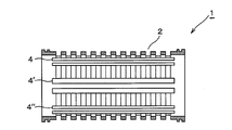
- FIG. 2 is a side view which shows the one aspect
- FIG. 2 is a cross-sectional view taken along the line AA ′ of the hollow fiber membrane module case shown in FIG. 1 (conventional embodiment).
- FIG. 2 is a cross-sectional view of the hollow fiber membrane module case taken along the line AA ′ of FIG.
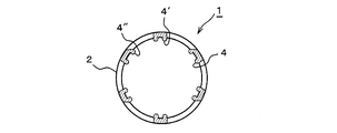
- FIG. 2 is a cross-sectional view taken along the line BB ′ of the hollow fiber membrane module case according to the present invention, in which R-shaped ribs are provided at the through hole edge portion inside the case shown in FIG. 1.
- the hollow fiber membrane module case of the present invention has a through-hole serving as a fluid flow path formed on a wall surface, and an R-shaped rib is provided at an acute-angled edge portion of the through-hole inside the case.
- the hole has a mesh.
- a cross-sectional shape of the R-shaped rib a shape that does not create an acute angle by being attached to an acute-angled portion of the acute-angled edge portion of the through hole, for example, a semicircular shape, etc. Is mentioned.
- FIG. 3 is a cross-sectional view of a case for a hollow fiber membrane module according to the present invention.
- the hollow fiber membrane module has a through-hole formed as a fluid flow path on the wall surface illustrated in FIG. It is sectional drawing of the AA 'line
- an injection molding method is generally used.
- FIG. 2 (conventional example) is shown.
- edges 3, 3 ′, 3 ′′,... are formed on the inner peripheral surface of the case 1 by the through-holes 2 formed on the wall surface of the case 1.
- R-type ribs 4 are formed.
- the R-shaped rib 4 is formed integrally with the edge portion when the case is injection molded.
- Patent Document 1 by providing a cover portion that protrudes in parallel so as to form a step with respect to the wall peripheral surface from the both ends in the axial direction of the inflow hole via the inclined connection portion, damage during housing of the hollow fiber membrane is prevented.
- the case for the hollow fiber membrane module according to the present invention has a simplified configuration without using a plurality of members as in this conventional example, and at the same time as the case injection molding Since a rib part can also be formed, it has the characteristic that manufacture of the case for hollow fiber membrane modules is easy.
- the R-shaped rib is formed on at least an acute edge among the edges formed at the time of manufacturing the case.
- the edge 3 'of the case wall surface located near the top and bottom apex is a right angle (90 degrees), so the formation of the R-shaped rib 4' is optional.
- FIG. 4 shows a cross section of a case for a hollow fiber membrane module according to the present invention, and a case for a hollow fiber membrane module in which a through hole serving as a fluid flow path is formed on the wall surface illustrated in FIG.
- FIG. 5 is a transverse cross-sectional view of the portion BB ′ of the hollow fiber membrane module case in which R-shaped ribs are formed at the edge portions of the through holes.
- R-shaped ribs 4, 4 ′, 4 ′′ R-shaped ribs 4, 4 ′, 4 ′′,.
- the R-shaped ribs 4, 4 ', 4 ", ... are formed in a rod shape in which adjacent edges are connected in the long axis direction of the case.
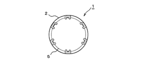
- the mesh 5 is preferably disposed in the through hole inside the case by a mesh insert molding method (FIG. 5).
- a mesh insert molding method As the mesh, resin or metal is used, and the case material is injected after inserting the mesh into the mold (insert), and the mesh member and the case material are integrated to form a through hole.
- a hollow fiber membrane module case is manufactured.
- the hollow fiber membrane module case accommodates a hollow fiber membrane bundle composed of a plurality of hollow fiber membranes, and each end of the hollow fiber membrane bundle is opened so that only the hollow interior of the hollow fiber membrane is open to the outside.
- a hollow fiber membrane module is configured by fixing the end portions of the hollow fiber membranes through potting portions in which the outer wall surfaces of the hollow fiber membranes and the inner wall surface of the case are sealed and fixed.
- this is a solid polymer fuel cell Effective as a humidifying hollow fiber membrane module used in humidifiers to humidify the fuel gas supplied to the air, as well as a dehumidifying hollow fiber membrane module, a hollow fiber membrane module used for fluid filtration, separation and concentration, etc. Used for.
Landscapes
- Chemical & Material Sciences (AREA)
- Chemical Kinetics & Catalysis (AREA)
- Life Sciences & Earth Sciences (AREA)
- Engineering & Computer Science (AREA)
- Manufacturing & Machinery (AREA)
- Sustainable Development (AREA)
- Sustainable Energy (AREA)
- Electrochemistry (AREA)
- General Chemical & Material Sciences (AREA)
- Fuel Cell (AREA)
- Separation Using Semi-Permeable Membranes (AREA)
- Air Humidification (AREA)
Abstract
壁面に流体の流路となる貫通穴2が設けられている中空糸膜モジュール用ケース1において、ケース内側の貫通穴鋭角エッジ部分にR型リブ4,4',4''、・・・・が設けられ、好ましくはケース内側の貫通穴にさらにメッシュを備えた中空糸膜モジュール用ケース。この中空糸膜モジュール用ケースは、従来から用いられてきた壁面に流体の流路となる貫通穴が設けられている中空糸膜モジュール用ケースと比べて、収容された中空糸膜のモジュール使用時における破損を低減せしめることを可能とする。
Description
本発明は、中空糸膜モジュール用ケースに関する。さらに詳しくは、燃料電池の加湿装置などとして有効に用いられる中空糸膜モジュール用のケースに関する。
現在、燃料電池などに用いられる加湿装置として、中空糸膜束をケースに挿嵌し、ケース端部でポッティング部を介して中空糸膜端部を固定せしめた中空糸膜モジュールが用いられている。これは、中空糸膜の内側にドライガス(乾燥空気;加湿対象)を、また中空糸膜の外側にウェットガス(湿潤空気)をそれぞれ通気することによりドライガスが加湿されるというものである。かかる中空糸膜モジュールに用いられるケースには、ウェットガスの流路となる貫通穴を設ける必要がある。
中空糸膜モジュール用ケースを量産するに際しては一般的に射出成型法が用いられるが、射出成型で貫通穴を設けたケースを作製した場合には、図2のケース断面図に示されるようにケース1壁面に形成された貫通穴2によりケース1内周面にエッジ3、3′、3′′、・・・・が形成されることとなる。かかるエッジ3、3′、3′′、・・・・は、通常用いられる二つ割りの金型を用いた場合には、上下頂部付近に位置するケース壁面のエッジ3′は直角(90度)となるものの、それ以外の箇所ではケース壁面に形成される内壁面側エッジ3、3′′、・・・・は鋭角となる。
例えば自動車用の燃料電池に使用される加湿膜モジュールには、数千NL/分と高流量でガスが流れることに加え、運転・停止の繰り返しあるいは運転負荷によりその流量が大きく変動するため、中空糸膜モジュール用ケース内に収容された中空糸膜が揺動し、モジュールケース内側のエッジに繰り返してあたることとなり、中空糸膜が破損するおそれがある。
本出願人は先に、中空糸膜モジュール組み立て時に発生する中空糸膜の破損を防止することを目的として、ハウジングケースに、その周壁面の一方の端部側から他方の端部側まで略軸方向に延びる複数本の枠の間に形成されるスリット状の流入孔を形成した中空糸膜モジュール用ケースを提案している(特許文献1参照)。かかる中空糸膜モジュール用ケースは、中空糸膜モジュール組み立て時に発生する中空糸膜の破損を有効に防止せしめるものの、流入孔にはエッジが存在することから、使用時においては中空糸膜が揺動し、中空糸膜がモジュールケース内側のエッジに繰り返してあたることとなり、中空糸膜が破損するおそれがある。これに対して、流入孔の軸方向の両端部から傾斜接続部を介し壁周面に対して段差をなすように平行に突出するカバー部を備えることにより、中空糸膜と流入孔とが直接接触しにくい態様についても提案している(特許文献1 段落〔0015〕、図3(b))。しかしながら、鋭角なエッジに対しての対応策については言及されておらず、またカバー部はケースとは別の部材として用意する必要があり、簡素化された構成とまではいえないものであった。
本発明の目的は、従来から用いられてきた壁面に流体の流路となる貫通穴が設けられている中空糸膜モジュール用ケースと比べて簡素化された構成で、収容された中空糸膜のモジュール使用時における破損を低減せしめることを可能とする中空糸膜モジュール用ケースを提供することにある。
かかる本発明の目的は、壁面に流体の流路となる貫通穴が設けられている中空糸膜モジュール用ケースにおいて、ケース内側の貫通穴鋭角エッジ部分にR型リブが設けられ、好ましくはケース内側の貫通穴にさらにメッシュを備えた中空糸膜モジュール用ケースによって達成される。
本発明に係る中空糸膜モジュール用ケースは、中空糸膜モジュール使用時に中空糸膜の破損原因となりうるケース内側の貫通穴鋭角エッジ部分にR型リブが設けられているので、ケース内に収容された中空糸膜の中空糸膜モジュール使用時における破損を低減せしめることができるといったすぐれた効果を奏する。このR型リブは、エッジ部分と一体的に形成されるため、かかる中空糸膜モジュール用ケースは構成が簡素化されており、容易にその製造が可能であるといった特徴を有する。
さらにケース内側の貫通穴にメッシュを備えることにより、鋭角エッジ以外の直角のエッジ部分についてはR型リブを設けなくとも中空糸膜の破損を有効に防止せしめることが可能となる。
本発明の中空糸膜モジュール用ケースは、壁面に流体の流路となる貫通穴が形成されており、ケース内側の貫通穴鋭角エッジ部分にR型リブが設けられ、好ましくはさらにケース内側の貫通穴にメッシュを備えている。ここで、R型リブの断面形状としては、貫通穴鋭角エッジ部分の鋭角箇所に取り付けられることにより該鋭角箇所を鈍角と成し、鋭角を創出することがない形状、例えば半円形状のものなどが挙げられる。
以下、図面を参照しながら本発明に係る中空糸膜モジュール用ケースの具体的態様を詳細に説明する。なお、以下に述べる具体的態様はあくまで本発明の一態様を例示しているに過ぎず、本発明はこれらの各態様に限定されるものではない。
図3は、本発明に係る中空糸膜モジュール用ケースの一断面を示したものであり、図1に例示されている壁面に流体の流路となる貫通穴が形成された中空糸膜モジュール用ケースのA-A′線部分の断面図である。従来の技術で述べた如く中空糸膜モジュール用ケースを量産するに際しては一般的に射出成型法が用いられ、射出成型で貫通穴を設けたケースを作製すると、図2(従来例)に示されるようにケース1壁面に形成された貫通穴2により、ケース1内周面にエッジ3、3′、3′′、・・・・が形成されることとなるが、本発明ではかかるエッジ部分にR型のリブ4を形成せしめることを特徴としている。かかるR型リブ4を設けることによって、ケース内に中空糸膜を収容した中空糸膜モジュール使用時に中空糸膜が揺動しても、中空糸膜がエッジ部分に繰り返し当たって中空糸膜が破損することを防ぐことが可能となる。
かかるR型リブ4は、ケースの射出成形時にエッジ部分と一体的に形成される。特許文献1では、流入孔の軸方向の両端部から傾斜接続部を介し壁周面に対して段差をなすように平行に突出するカバー部を備えることにより、中空糸膜の収容時における破損を防止するといった態様が示されているが、本発明に係る中空糸膜モジュール用ケースはこの従来例のように複数の部材を用いることなく簡素化された構成で、かつケースの射出成形時と同時にリブ部も形成しうるので、中空糸膜モジュール用ケースの製造が容易であるといった特徴を有する。
R型リブは、ケース製造時に形成されるエッジのうち、少なくとも鋭角となるものについて形成される。通常用いられる二つ割りの金型を用いた場合には、上下頂部付近に位置するケース壁面のエッジ3′は直角(90度)となるので、R型リブ4′の形成は任意である。またケース製造時に形成されるエッジが鈍角の部分についても同様である。したがって、本発明では、R型リブが鋭角のエッジ部分のみに形成される態様および鋭角のエッジ部分に加えて鋭角エッジ部分以外のエッジ部分にもR型リブが形成された態様のいずれをも含む。
図4は本発明に係る中空糸膜モジュール用ケースの一断面を示したものであり、図1に例示されている壁面に流体の流路となる貫通穴が形成された中空糸膜モジュール用ケースの貫通穴エッジ部分にR型リブが形成された中空糸膜モジュール用ケースのB-B’線部分の横断面図である。図4では、エッジのすべてにR型リブ4、4′、4′′、・・・・が設けられている。この図では、R型リブ4、4′、4′′、・・・・は隣り合うエッジ同士をケースの長軸方向に繋いだ棒状に形成されている。
ここで、射出成型によるケース製造時には、好ましくはメッシュインサート成型法によりケース内側の貫通穴にメッシュ5が配置される(図5)。メッシュとしては、樹脂製あるいは金属製のものが用いられ、メッシュを金型に装着(インサート)後にケース材料を注入し、メッシュ部材とケース材料とを一体化させることにより、貫通穴が形成された中空糸膜モジュール用ケースの製造が行われる。このようにケース内側の貫通穴にメッシュを備えることにより、鋭角エッジ以外の直角のエッジ部分、すなわちエッジ3および貫通穴によって円周方向に形成されるエッジ(図示せず)については、R型リブを設けなくとも中空糸膜の破損を有効に防止せしめることが可能となり、また貫通穴がケース長軸方向に形成されている場合であっても、中空糸膜のケース外への突出を有効に防止することができる。
本発明に係る中空糸膜モジュール用ケースは、複数の中空糸膜からなる中空糸膜束を収容し、中空糸膜束端部を中空糸膜の中空内部のみが外部に開放されるように各中空糸膜の外壁面間およびケースの内壁面間を封止固定したポッティング部を介して中空糸膜端部を固定せしめることによって中空糸膜モジュールを構成し、これは例えば固体高分子型燃料電池に供給する燃料ガスを加湿するための加湿器等に使用される加湿用中空糸膜モジュールのほか、除湿用中空糸膜モジュール、流体のろ過、分離、濃縮に用いられる中空糸膜モジュールなどとして有効に用いられる。
1 中空糸膜モジュール用ケース
2 貫通穴
3,3′,3′′ エッジ
4,4′,4′′ R型リブ
5 メッシュ
2 貫通穴
3,3′,3′′ エッジ
4,4′,4′′ R型リブ
5 メッシュ
Claims (12)
- ケース壁面に流体の流路となる貫通穴が設けられている中空糸膜モジュール用ケースにおいて、
ケース内側の貫通穴鋭角エッジ部分にR型リブが設けられた中空糸膜モジュール用ケース。 - 鋭角エッジ部分に加えて、鋭角エッジ部分以外のエッジ部分にR型リブが設けられた請求項1記載の中空糸膜モジュール用ケース。
- R型リブが、隣り合うエッジ同士をケースの長軸方向に繋いだ棒状に形成されている請求項1または2記載の中空糸膜モジュール用ケース。
- 射出成型法によって製造された請求項1、2または3記載の中空糸膜モジュール用ケース。
- さらにケース内側の貫通穴にメッシュを備えた請求項1または2記載の中空糸膜モジュール用ケース。
- メッシュインサート成型法によってメッシュが形成された請求項5記載の中空糸膜モジュール用ケース。
- 請求項1記載の中空糸膜モジュールケースに複数の中空糸膜からなる中空糸膜束を収容し、中空糸膜束端部を中空糸膜の中空内部のみが外部に開放されるように各中空糸膜の外壁面間およびケースの内壁面間を封止固定したポッティング部を備えた中空糸膜モジュール。
- 請求項5記載の中空糸膜モジュールケースに複数の中空糸膜からなる中空糸膜束を収容し、中空糸膜束端部を中空糸膜の中空内部のみが外部に開放されるように各中空糸膜の外壁面間およびケースの内壁面間を封止固定したポッティング部を備えた中空糸膜モジュール。
- 加湿装置として用いられる請求項7記載の中空糸膜モジュール。
- 加湿装置として用いられる請求項8記載の中空糸膜モジュール。
- 加湿装置が、燃料電池の加湿装置である請求項9記載の中空糸膜モジュール。
- 加湿装置が、燃料電池の加湿装置である請求項10記載の中空糸膜モジュール。
Applications Claiming Priority (2)
| Application Number | Priority Date | Filing Date | Title |
|---|---|---|---|
| JP2012-240359 | 2012-10-31 | ||
| JP2012240359A JP2015037767A (ja) | 2012-10-31 | 2012-10-31 | 中空糸膜モジュール用ケース |
Publications (1)
| Publication Number | Publication Date |
|---|---|
| WO2014069162A1 true WO2014069162A1 (ja) | 2014-05-08 |
Family
ID=50627078
Family Applications (1)
| Application Number | Title | Priority Date | Filing Date |
|---|---|---|---|
| PCT/JP2013/077111 Ceased WO2014069162A1 (ja) | 2012-10-31 | 2013-10-04 | 中空糸膜モジュール用ケース |
Country Status (2)
| Country | Link |
|---|---|
| JP (1) | JP2015037767A (ja) |
| WO (1) | WO2014069162A1 (ja) |
Cited By (1)
| Publication number | Priority date | Publication date | Assignee | Title |
|---|---|---|---|---|
| JP2018505053A (ja) * | 2015-02-12 | 2018-02-22 | コーロン インダストリーズ インク | 中空糸膜バンドル及びその製造方法 |
Families Citing this family (4)
| Publication number | Priority date | Publication date | Assignee | Title |
|---|---|---|---|---|
| KR102137231B1 (ko) * | 2018-11-30 | 2020-07-23 | (주)바이오데이즈 | 중공사막 맴브레인 필터 제습장치가 구비된 태양열 히트 펌프 냉난방시스템 |
| KR102844832B1 (ko) * | 2021-09-02 | 2025-08-08 | 코오롱인더스트리 주식회사 | 막가습기용 카트리지 및 이를 포함하는 연료전지 막가습기 |
| EP4670827A1 (en) * | 2023-02-21 | 2025-12-31 | NOK Corporation | HOLLOW FIBER MEMBRANE MODULE |
| KR20240163776A (ko) * | 2023-05-11 | 2024-11-19 | 코오롱인더스트리 주식회사 | 연료전지용 가습기 |
Citations (7)
| Publication number | Priority date | Publication date | Assignee | Title |
|---|---|---|---|---|
| JPH08206468A (ja) * | 1995-02-07 | 1996-08-13 | Daisen Menburen Syst Kk | 中空糸型膜モジュール |
| JPH1057777A (ja) * | 1996-08-14 | 1998-03-03 | Nok Corp | 中空糸膜モジュール |
| JP2001137840A (ja) * | 1999-11-15 | 2001-05-22 | Matsushita Electric Works Ltd | 浄水カートリッジ |
| JP2002370018A (ja) * | 2001-06-15 | 2002-12-24 | Nok Corp | 中空糸膜モジュール |
| JP2004006099A (ja) * | 2002-05-31 | 2004-01-08 | Nok Corp | 燃料電池の加湿装置 |
| JP2005155994A (ja) * | 2003-11-25 | 2005-06-16 | Nissan Motor Co Ltd | 中空糸膜加湿器 |
| WO2008035593A1 (en) * | 2006-09-19 | 2008-03-27 | Toray Industries, Inc. | Hollow fiber membrane module |
-
2012
- 2012-10-31 JP JP2012240359A patent/JP2015037767A/ja active Pending
-
2013
- 2013-10-04 WO PCT/JP2013/077111 patent/WO2014069162A1/ja not_active Ceased
Patent Citations (7)
| Publication number | Priority date | Publication date | Assignee | Title |
|---|---|---|---|---|
| JPH08206468A (ja) * | 1995-02-07 | 1996-08-13 | Daisen Menburen Syst Kk | 中空糸型膜モジュール |
| JPH1057777A (ja) * | 1996-08-14 | 1998-03-03 | Nok Corp | 中空糸膜モジュール |
| JP2001137840A (ja) * | 1999-11-15 | 2001-05-22 | Matsushita Electric Works Ltd | 浄水カートリッジ |
| JP2002370018A (ja) * | 2001-06-15 | 2002-12-24 | Nok Corp | 中空糸膜モジュール |
| JP2004006099A (ja) * | 2002-05-31 | 2004-01-08 | Nok Corp | 燃料電池の加湿装置 |
| JP2005155994A (ja) * | 2003-11-25 | 2005-06-16 | Nissan Motor Co Ltd | 中空糸膜加湿器 |
| WO2008035593A1 (en) * | 2006-09-19 | 2008-03-27 | Toray Industries, Inc. | Hollow fiber membrane module |
Cited By (1)
| Publication number | Priority date | Publication date | Assignee | Title |
|---|---|---|---|---|
| JP2018505053A (ja) * | 2015-02-12 | 2018-02-22 | コーロン インダストリーズ インク | 中空糸膜バンドル及びその製造方法 |
Also Published As
| Publication number | Publication date |
|---|---|
| JP2015037767A (ja) | 2015-02-26 |
Similar Documents
| Publication | Publication Date | Title |
|---|---|---|
| WO2014069162A1 (ja) | 中空糸膜モジュール用ケース | |
| KR20230146064A (ko) | 중공 사막 모듈 | |
| KR20130034404A (ko) | 연료전지용 가습기 | |
| US20160226084A1 (en) | Fuel cell case and ventilation cover | |
| JP4852873B2 (ja) | 中空糸膜モジュールの製造方法 | |
| CN111683730B (zh) | 中空纤维膜组件 | |
| KR20230146057A (ko) | 중공 사막 모듈 및 제가습 장치 | |
| JP2007216176A (ja) | 中空糸膜モジュール | |
| JP2004202478A (ja) | 膜モジュール | |
| US20240173675A1 (en) | Hollow fiber membrane module and dehumidification/humidification device | |
| JP7685049B2 (ja) | 中空糸膜モジュール及び除加湿装置 | |
| JP2014117651A (ja) | 加湿膜ユニット | |
| JP2007216175A (ja) | 中空糸膜モジュールとその製造方法 | |
| KR101221300B1 (ko) | 가습공기청정기용 디스크 어셈블리 | |
| EP4725590A1 (en) | Hollow fiber membrane module | |
| JP2019058896A (ja) | 中空糸膜モジュール | |
| CA3288693A1 (en) | Hollow fiber membrane module | |
| KR102200197B1 (ko) | 조립형 복합재 프로펠러 | |
| KR101303517B1 (ko) | 가습공기청정기용 디스크 어셈블리 | |
| KR101221176B1 (ko) | 가습공기청정기용 디스크 어셈블리 | |
| JP2022087878A (ja) | 中空糸膜モジュール | |
| EP4670827A1 (en) | HOLLOW FIBER MEMBRANE MODULE | |
| EP4670828A1 (en) | HOLLOW FIBER MEMBRANE MODULE | |
| CA3276360A1 (en) | Hollow fiber membrane module | |
| JPH11169675A (ja) | 中空糸膜モジュール |
Legal Events
| Date | Code | Title | Description |
|---|---|---|---|
| 121 | Ep: the epo has been informed by wipo that ep was designated in this application |
Ref document number: 13851176 Country of ref document: EP Kind code of ref document: A1 |
|
| NENP | Non-entry into the national phase |
Ref country code: DE |
|
| 122 | Ep: pct application non-entry in european phase |
Ref document number: 13851176 Country of ref document: EP Kind code of ref document: A1 |