WO2014068879A1 - 配信装置、通信システム、負荷分散方法および負荷分散プログラム - Google Patents
配信装置、通信システム、負荷分散方法および負荷分散プログラム Download PDFInfo
- Publication number
- WO2014068879A1 WO2014068879A1 PCT/JP2013/006159 JP2013006159W WO2014068879A1 WO 2014068879 A1 WO2014068879 A1 WO 2014068879A1 JP 2013006159 W JP2013006159 W JP 2013006159W WO 2014068879 A1 WO2014068879 A1 WO 2014068879A1
- Authority
- WO
- WIPO (PCT)
- Prior art keywords
- connection continuation
- terminal
- continuation signal
- time
- connection
- Prior art date
- Legal status (The legal status is an assumption and is not a legal conclusion. Google has not performed a legal analysis and makes no representation as to the accuracy of the status listed.)
- Ceased
Links
Images




Classifications
-
- H—ELECTRICITY
- H04—ELECTRIC COMMUNICATION TECHNIQUE
- H04L—TRANSMISSION OF DIGITAL INFORMATION, e.g. TELEGRAPHIC COMMUNICATION
- H04L43/00—Arrangements for monitoring or testing data switching networks
- H04L43/10—Active monitoring, e.g. heartbeat, ping or trace-route
-
- H—ELECTRICITY
- H04—ELECTRIC COMMUNICATION TECHNIQUE
- H04L—TRANSMISSION OF DIGITAL INFORMATION, e.g. TELEGRAPHIC COMMUNICATION
- H04L43/00—Arrangements for monitoring or testing data switching networks
- H04L43/16—Threshold monitoring
-
- H—ELECTRICITY
- H04—ELECTRIC COMMUNICATION TECHNIQUE
- H04L—TRANSMISSION OF DIGITAL INFORMATION, e.g. TELEGRAPHIC COMMUNICATION
- H04L47/00—Traffic control in data switching networks
- H04L47/10—Flow control; Congestion control
- H04L47/12—Avoiding congestion; Recovering from congestion
- H04L47/125—Avoiding congestion; Recovering from congestion by balancing the load, e.g. traffic engineering
-
- H—ELECTRICITY
- H04—ELECTRIC COMMUNICATION TECHNIQUE
- H04L—TRANSMISSION OF DIGITAL INFORMATION, e.g. TELEGRAPHIC COMMUNICATION
- H04L67/00—Network arrangements or protocols for supporting network services or applications
- H04L67/50—Network services
- H04L67/55—Push-based network services
-
- H—ELECTRICITY
- H04—ELECTRIC COMMUNICATION TECHNIQUE
- H04L—TRANSMISSION OF DIGITAL INFORMATION, e.g. TELEGRAPHIC COMMUNICATION
- H04L69/00—Network arrangements, protocols or services independent of the application payload and not provided for in the other groups of this subclass
- H04L69/28—Timers or timing mechanisms used in protocols
-
- H—ELECTRICITY
- H04—ELECTRIC COMMUNICATION TECHNIQUE
- H04L—TRANSMISSION OF DIGITAL INFORMATION, e.g. TELEGRAPHIC COMMUNICATION
- H04L47/00—Traffic control in data switching networks
- H04L47/10—Flow control; Congestion control
- H04L47/28—Flow control; Congestion control in relation to timing considerations
Definitions
- the present invention relates to a distribution device, a communication system, a load distribution method, and a load distribution program for providing an event notification service to a user.
- VoIP (Voice over Internet Protocol) incoming notification and SNS (Social Networking Service) update notification such as an VoIP (Voice over Internet Protocol) incoming notification
- VoIP Voice over Internet Protocol
- SNS Social Networking Service
- VoIP Voice over Internet Protocol
- VoIP Voice over Internet Protocol
- a server device that transmits a push message sends a notification request such as a VoIP incoming notification, an SNS update notification, chat message distribution, or a cloud storage update notification to a service provider server (hereinafter referred to as an application server).
- the application server is a server device used by a service provider such as an SNS administrator.
- the service provider uses the application server to request the push server to deliver a message addressed to application software (hereinafter simply referred to as an application) provided by the service provider.
- the service provider provides an application for using the service to the user in advance. And a user operates the application provided from the service provider on a terminal.
- the push server transmits a push message to software (hereinafter referred to as a push client) operating on the terminal in accordance with the message delivery request.
- the push client passes the received message to the destination application.
- the application performs processing according to the content of the message received from the push client. For example, the application notifies the user of information or communicates with the content server to acquire updated content from the content server.
- Terminals use various networks such as mobile networks and wireless LANs.
- the terminal may be under the NAT (Network Address Translation).
- NAT Network Address Translation
- a router having a NAT function may be installed between the push server and the terminal.
- a router equipped with a NAT function converts a global address and a private address of a terminal using a NAT conversion table.
- the NAT conversion table is information in which the IP address and port of the terminal are associated with the port of the router.
- FIG. 8 is an explanatory diagram showing an example of the NAT conversion table. “Address” shown in FIG. 8 represents the IP address of the terminal.
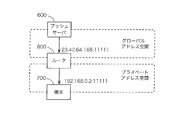
- FIG. 9 is an explanatory diagram showing how packets are transferred from the push server to the terminal via the router.
- a terminal 700 shown in FIG. 9 is connected to a push server 600 via a router 800 having a NAT function. That is, the terminal 700 is arranged under the NAT.
- the router 800 updates the NAT conversion table. Specifically, the router 800 stores the private address of the terminal and the port number used by the push client in the NAT conversion table.
- the private address is “192.168.0.2” and the port number is “11111”.
- the global address of the router is “23.42.64.168”.
- the router 800 converts the source address to the global address of the own device when transferring the packet received from the terminal 700 to the push server 600. Therefore, the push server 600 recognizes not the private address of the terminal 700 but the global address of the router 800 as the source address. Therefore, when the push server 600 transmits a packet to the terminal 700, the push server 600 transmits the packet to the global address of the router 800. When receiving the packet from the push server 600, the router 800 converts the destination address into the private address of the terminal 700 based on the NAT conversion table, and forwards the packet to the terminal 700.
- the IP address and port number of the terminal stored in the NAT conversion table are deleted from the NAT conversion table due to timeout when there is no communication for a certain period of time. Thereafter, the router cannot convert the destination address of the packet received from the push server to the terminal into the private address of the terminal. Therefore, packets transmitted from the push server do not reach the terminal. Therefore, in order to maintain the TCP connection between the push server and the terminal normally, it is necessary to periodically communicate between the push server and the terminal so that the NAT conversion table does not time out. In order to maintain the connection, a signal periodically transmitted and received between the push server and the terminal is referred to as a keep alive signal (hereinafter also referred to as a connection continuation signal).
- a keep alive signal hereinafter also referred to as a connection continuation signal.
- the terminal When the terminal uses a mobile network such as a 3G line or LTE (Long Term Evolution), the terminal switches the radio state according to the communication state in order to save power. For example, the terminal sets the wireless state to a standby state or an active state according to the communication state. When switching the radio state, the terminal transmits / receives a control signal for switching the radio state to / from the mobile network.
- the wireless state of the terminal When an application running on a terminal periodically generates communication, the wireless state of the terminal repeatedly alternates between a standby state and an active state, and a large number of control signals flow through the mobile network. Congestion occurs.
- FIG. 10 is an explanatory diagram showing the transmission cycle of the keep-alive signal.
- the NAT conversion table held by the router varies depending on the router. For example, the timeout time of the NAT conversion table is different for each router. Accordingly, various values can be set for the transmission cycle of the keep-alive signal for the terminal depending on the router connected to the terminal.
- FIG. 10A is a waveform representing a transmission cycle of a keep alive signal transmitted from the push server to each terminal.
- FIG. 10B is a waveform obtained by superimposing the waveforms for each terminal shown in FIG.
- FIG. 10A when the transmission cycle of the keep alive signal for each terminal is different, there is a moment (a portion surrounded by a dotted line shown in FIG. 10) where the transmission times of the keep alive signal for each terminal are concentrated. . At that time, the load on the push server may increase.
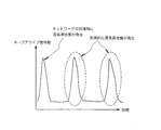
- FIG. 11 is an explanatory diagram showing an increase / decrease in the number of keep-alive signals when a network failure is recovered.
- the connection between the push server and each terminal may be interrupted due to a network failure or the like. In that case, when the network failure is recovered, reconnection between the push server and each terminal is performed simultaneously. Thereafter, until each terminal starts communication, a keep-alive signal is periodically transmitted and received between the push server and each terminal. In the meantime, as shown in FIG. 11, moments (locations surrounded by dotted lines shown in FIG. 11) at which the transmission times of keep-alive signals for each terminal are concentrated periodically occur. Therefore, the load on the push server may increase regularly.
- a communication system that can easily connect to a device in a LAN to which a private IP address is assigned from a terminal on the Internet side at a desired timing (for example, , See Patent Document 1).
- a server device installed on the Internet side transfers communication between a terminal and a device.
- a device in the LAN transmits a keep alive packet to the server device in order to maintain a connection with the server device even when the device is not communicating with the terminal.
- the server device determines the transmission cycle of the keep-alive packet and sets the determined transmission cycle in the device. Therefore, the server device can change the length of the keep-alive packet transmission cycle according to the reception load of the device itself.
- the server device controls only the transmission cycle of the keep alive packet of each terminal, there is a possibility that the keep alive packet is simultaneously transmitted from many terminals. In this case, the server device is in a high load state, and real time communication between the terminal and the device may be impaired.
- the present invention provides a distribution device, a communication system, and a load capable of distributing the processing load for continuing the connection with the terminal in time and maintaining the real-time property of message distribution in the event notification service.
- An object is to provide a distribution method and a load distribution program.
- the distribution apparatus includes a communication unit that transmits a connection continuation signal for maintaining a connection between the terminal and the terminal to each terminal connected to the terminal when there is no data to be distributed; Divides the period during which the unit transmits the connection continuation signal into a plurality of time intervals, and calculates the number of connection continuation signal transmissions scheduled for each time interval based on the connection continuation signal interval information indicating the connection continuation signal interval for each terminal.
- a transmission time determination unit that causes the communication unit to transmit a connection continuation signal for the amount exceeding the threshold in a time period before the time period. It is characterized by having.
- a communication system includes a distribution device and a plurality of terminals capable of communicating with the distribution device, and the terminal specifies a connection continuation signal interval for maintaining a connection between the distribution device and the own terminal.
- a connection continuation control unit for notifying the distribution device of continuation signal interval information, the distribution device transmitting a connection continuation signal to each terminal when there is no data to be distributed, and the communication unit transmitting a connection continuation signal Dividing the period to be divided into a plurality of time intervals, calculating the number of scheduled connection continuation signal transmissions for each time interval based on the connection continuation signal interval information received from each terminal, and setting a predetermined threshold for the number of scheduled transmissions. If it exceeds, the communication unit includes a transmission time determination unit that transmits a connection continuation signal exceeding the threshold in a time interval before the time interval.
- a distribution device that transmits a connection continuation signal for maintaining a connection between the device and the terminal to each terminal connected to the device Dividing the period for transmitting the connection continuation signal into a plurality of time intervals, calculating the number of connection continuation signal transmissions scheduled for each time interval based on the connection continuation signal interval information indicating the interval of the connection continuation signal for each terminal, When the scheduled transmission number exceeds a predetermined threshold, a connection continuation signal for the amount exceeding the threshold is transmitted in a time interval before the time interval.
- the load distribution program is a process for transmitting a connection continuation signal for maintaining the connection between the computer and each terminal to each terminal connected to the computer when there is no data to be distributed. And dividing the period for transmitting the connection continuation signal into a plurality of time intervals, and calculating the number of connection continuation signal transmissions scheduled for each time interval based on the connection continuation signal interval information indicating the connection continuation signal interval for each terminal.
- a process of transmitting a connection continuation signal corresponding to the threshold value exceeding the predetermined time period is executed. .
- the processing load for continuing the connection between the push server and the terminal can be distributed over time, and the real-time property of message delivery can be maintained.
- Embodiment 1 FIG. A first embodiment of the present invention will be described below with reference to the drawings.
- FIG. 1 is a block diagram showing a configuration of a first embodiment of a communication system according to the present invention.
- a communication system according to the present invention (hereinafter referred to as a message distribution system) includes a push server 100, terminals 200-1 to 200-n, and a router 300.
- a router 300 In FIG. 1, one router 300 is illustrated, but any number of routers may be connected.
- the push server 100 includes a message transmission request reception unit 110, a message queue 120, a message transmission unit 130, a connection continuation signal transmission / reception unit 140, a connection continuation signal transmission time determination unit 150, and a scheduled transmission time information storage unit 160. including.
- the message transmission request receiving unit 110 receives a message transmission request and a message corresponding to the message transmission request from an application server (not shown) that can communicate with the push server 100.
- the message transmission request receiving unit 110 receives a push message as a message corresponding to the message transmission request.
- the message queue 120 stores a push message corresponding to the message transmission request.
- the message transmission unit 130 transmits a push message to the terminals 200-1 to 200-n. Specifically, the message transmission unit 130 transmits the push message stored in the message queue 120 to the terminals 200-1 to 200-n in response to the message transmission request received by the message transmission request reception unit 110.
- connection continuation signal transmission / reception unit 140 performs a keep-alive signal transmission / reception process with the terminals 200-1 to 200-n.
- connection continuation signal transmission time determination unit 150 determines the scheduled transmission time of the keep alive signal that the connection continuation signal transmission / reception unit 140 transmits to each terminal.
- the scheduled transmission time information storage unit 160 stores information indicating the scheduled transmission time determined by the connection continuation signal transmission time determination unit 150.
- the message transmission request receiving unit 110, the message transmission unit 130, the connection continuation signal transmission / reception unit 140, and the connection continuation signal transmission time determination unit 150 are realized by a CPU or the like provided in the push server 100.
- the message queue 120 and the scheduled transmission time information storage unit 160 are realized by a storage device such as a memory provided in the push server 100.
- the terminals 200-1 to 200-n are communication terminals such as mobile phones.
- the terminal 200-1 includes a message receiving unit 210, a message notification unit 220, and a connection continuation control unit 230.
- the message reception unit 210, the message notification unit 220, and the connection continuation control unit 230 operate on the terminal as a push client.
- the configuration of the terminals 200-2 to 200-n is the same as that of the terminal 200-1, and thus the description thereof is omitted.
- the message receiving unit 210 receives a push message distributed from the push server 100.
- the message notification unit 220 passes the push message to the application operating on the terminal.
- connection continuation control unit 230 transmits and receives a keep alive signal to and from the push server 100.
- the message reception unit 210, the message notification unit 220, and the connection continuation control unit 230 are realized by a CPU or the like provided in the terminal 200-1.
- the router 300 is a router device having a NAT function.
- the router 300 relays communication between the push server 100 and the terminals 200-1 to 200-n using the NAT function.
- the router 300 includes a packet transfer unit 310 and a NAT conversion table 320.
- the packet transfer unit 310 transfers a packet transmitted and received between the push server 100 and the terminals 200-1 to 200-n based on information stored in the NAT conversion table 320.
- the NAT conversion table 320 is information indicating the correspondence between the terminal global address and the private address.
- the packet transfer unit 310 is realized by a CPU or the like included in the router 300.
- the NAT conversion table 320 is realized by a storage device such as a memory provided in the router 300.
- long polling the HTTP long polling method
- the HTTP response when there is a push message to be delivered to the terminal by the push server in response to the HTTP request from the terminal, an HTTP response including the push message is immediately transmitted, and there is no push message to be delivered to the terminal. In this case, the response is suspended until a push message to be delivered to the terminal is generated.
- the HTTP response and the subsequent HTTP response are used as a keep alive signal.
- the push server that has received the HTTP request for long polling transmits, to the terminal, an HTTP response that does not include the push message as a keep-alive signal when the requesting terminal reaches a predetermined time.
- the terminal that has received the HTTP response transmits a long polling HTTP request again.
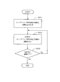
- FIG. 2 is a flowchart showing the adjustment processing of the scheduled keep-alive signal transmission number.
- the connection continuation control unit 230 of each of the terminals 200-1 to 200-n previously specifies information for designating the transmission interval of the keep alive signal to the push server 100 (hereinafter referred to as keep alive interval information or connection continuation signal interval information). .)
- the connection continuation signal transmission / reception unit 140 of the push server 100 holds keep alive interval information received from each terminal.
- the push server 100 may hold the keep alive interval information of each terminal in advance.
- the user may store the keep alive interval information of each terminal in advance in a storage unit (not shown) of the push server 100.
- connection continuation signal transmission time determination unit 150 of the push server 100 creates a time distribution of the number of scheduled keepalive signal transmissions based on the keepalive interval information for each terminal held by the connection continuation signal transmission / reception unit 140 (step S201). ).
- step S201 a process of creating a time distribution of the number of planned keep-alive signal transmissions in step S201 will be described.
- the connection continuation signal transmission time determination unit 150 creates a time distribution of the number of scheduled keep-alive signal transmissions for the period in which the connection continuation signal transmission / reception unit 140 transmits the connection continuation signal.
- the connection continuation signal transmission time determination unit 150 creates a time distribution in units of, for example, 5 minutes.
- a period that is a unit for creating a time distribution (hereinafter referred to as a distribution creation period) may be set in advance by a user, for example, or the connection continuation signal transmission time determination unit 150 may operate in accordance with the load of the push server 100. It may be set automatically.
- connection continuation signal transmission time determination unit 150 divides the distribution creation period by the time interval ⁇ t. ⁇ t is set in advance by the user, for example.
- the connection continuation signal transmission time determination unit 150 calculates the scheduled transmission time of the keep alive signal for each terminal based on the keep alive interval information for each terminal held by the connection continuation signal transmission / reception unit 140.
- the connection continuation signal transmission time determination unit 150 stores the calculated transmission scheduled time in the transmission scheduled time information storage unit 160.
- connection continuation signal transmission time determination unit 150 adjusts the scheduled keep-alive signal transmission number for each section (step S202).
- FIG. 3 is a flowchart showing the operation of the connection continuation signal transmission time determination unit 150 in step S202.
- connection continuation signal transmission time determination unit 150 compares the scheduled keep alive signal transmission number Nk in the section k with the threshold T of the planned keep alive signal transmission number per section (step S301).
- the threshold T may be set in advance by a user or the like, or the connection continuation signal transmission time determination unit 150 may dynamically determine it according to the load of the push server 100.
- the connection continuation signal transmission time determination unit 150 when the scheduled keep alive signal transmission number Nk in the section k is equal to or less than the threshold T (No in step S301), Do not adjust.
- the scheduled keep alive signal transmission number Nk in the section k exceeds the threshold T (Yes in step S301)
- the keep alive signal of the part exceeding the threshold T (Nk ⁇ T) is transmitted in the section before the section k.
- the connection continuation signal transmission time determination unit 150 keeps the keep alive signal for the portion (Nk ⁇ T) exceeding the threshold T in the section k ⁇ 1 immediately before the section k. Adjust the scheduled number of alive signal transmissions.
- FIG. 4 is an explanatory diagram showing how the scheduled number of keep-alive signal transmissions is adjusted.
- the graph shown in FIG. 4 represents the planned keep-alive signal transmission count for each section.
- the shaded portion in the graph represents a keep-alive signal that exceeds the threshold in the interval k.
- the connection continuation signal transmission time determination unit 150 identifies a keep alive signal whose scheduled keep alive transmission time is included in the interval k, and selects Nk-T keep alive signals from among the keep alive signals. (Step S302).
- the connection continuation signal transmission time determination unit 150 shifts the scheduled transmission time of the keep alive signal forward so that the transmission of the selected Nk-T keep alive signals is executed in the section k ⁇ 1 (step S303). . That is, the connection continuation signal transmission time determination unit 150 updates the scheduled transmission time of the keep alive signal stored in the transmission scheduled time information storage unit 160 to the time one segment before.
- the connection continuation signal transmission time determination unit 150 confirms whether or not the adjustment processing of the scheduled keep alive signal transmission number has been completed for all the sections in the distribution creation period (step S203). If the adjustment process has not been completed for all the sections (No in step S203), the connection continuation signal transmission time determination unit 150 returns to the process in step S202. When the adjustment process is completed for all the sections (Yes in step S203), the connection continuation signal transmission time determination unit 150 ends the process for the distribution creation period.
- TCP original communication is a communication method on TCP originally developed by users and the like.
- TCP unique communication both a case where a keep-alive signal is transmitted from the push server and a case where a keep-alive signal is transmitted from the terminal are assumed.
- the side that received the keep-alive signal returns a response to the side that transmitted it.
- a message (PING message) including a character string “PING” is transmitted as a keep-alive signal in TCP original communication.
- the side receiving the PING message returns a message including the character string “PONG” as a response.
- the keep-alive signal in the TCP unique communication may be another message.
- the adjustment process of the number of scheduled keep-alive signal transmissions in the TCP original communication in which the keep-alive signal is transmitted from the push server is the same as that in the case of using the long polling, so the description is omitted.
- connection continuation signal transmission time determination unit 150 creates a time distribution of the scheduled keep alive signal reception number instead of the time distribution of the scheduled keep alive signal transmission number.
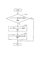
- FIG. 5 is a flowchart showing the adjustment process of the scheduled number of keep-alive signals received.
- the connection continuation control unit 230 of the terminals 200-1 to 200-n transmits the keep alive signal
- the next transmission of the keep alive signal to the push server 100 is performed. Notify the time.
- the connection continuation signal transmission / reception unit 140 of the push server 100 holds the next transmission time received from each terminal.
- the connection continuation signal transmission time determination unit 150 of the push server 100 creates a time distribution of the number of scheduled keepalive signal receptions based on the next transmission time of the keepalive signal for each terminal held by the connection continuation signal transmission / reception unit 140. (Step S501).
- the connection continuation signal transmission time determination unit 150 creates a time distribution for the distribution creation period, similarly to the process in step S201.
- step S501 first, the connection continuation signal transmission time determination unit 150 calculates a keep alive signal reception scheduled time of each terminal based on the next transmission time for each terminal held by the connection continuation signal transmission / reception unit 140.
- the connection continuation signal transmission time determination unit 150 calculates the number of scheduled keep-alive signal receptions for each section k in which the distribution creation period is divided by ⁇ t, based on the calculated keep-alive signal reception scheduled time.
- connection continuation signal transmission time determination unit 150 adjusts the number of scheduled keep-alive signal receptions for each section (step S502).
- step S502 the connection continuation signal transmission time determination unit 150 compares the planned number of keep alive signals received in the section k with the threshold value of the number of scheduled keep alive signals received per section.
- the connection continuation signal transmission time determination unit 150 keeps the keep alive signal not to be received in the section k when the scheduled number of keep alive signals received in the section k exceeds the threshold. Adjust the number of scheduled signal receptions.
- the connection continuation signal transmission time determination unit 150 identifies keep alive signals whose keep alive signal reception scheduled time is included in the interval k, and selects the keep alive signals for which the threshold value has been exceeded. To do.
- the connection continuation signal transmission time determination unit 150 identifies the terminal that is the transmission source of the keep alive signal that exceeds the threshold.
- the connection continuation signal transmission time determination unit 150 sets the scheduled transmission time of the keep alive signal and transmits the set transmission so that the keep alive signal is transmitted to the identified terminal in the section before the section k.
- the scheduled time is stored in the scheduled transmission time information storage unit 160.
- the connection continuation signal transmission time determination unit 150 sets the scheduled transmission time of the keep alive signal so that the keep alive signal is transmitted in the section k ⁇ 1 immediately before the section k.
- the keep alive signal is transmitted from the connection continuation signal transmission / reception unit 140 to the terminal specified by the connection continuation signal transmission time determination unit 150.
- the keep alive signal of the terminal is transmitted. Can be deterred. Accordingly, it is possible to prevent the push server 100 from receiving the keep-alive signal for the portion exceeding the threshold in the section k.
- the connection continuation signal transmission time determination unit 150 confirms whether or not the adjustment processing of the number of scheduled keep-alive signal receptions has been completed for all sections within the distribution creation period (step S503). If the adjustment process has not been completed for all the sections (No in step S503), the connection continuation signal transmission time determination unit 150 returns to the process in step S502. When the adjustment process is completed for all the sections (Yes in step S503), the connection continuation signal transmission time determination unit 150 ends the process for the distribution creation period.
- the keep-alive signal is transmitted so that the reception time of the keep-alive signal transmitted from each terminal is not concentrated. Adjust the number of scheduled receptions. As a result, the same effect as when using long polling can be obtained.
- the long-polling or TCP unique communication is used to transmit and receive the keep-alive signal.
- other methods may be used to transmit and receive the keep-alive signal. Good.
- connection continuation signal transmission time determination unit 150 exemplifies the case where the time distribution is generated in units of a fixed time (5 minutes). However, a predetermined number of keep-alive signals are transmitted. You may make it produce time distribution for every.
- the communication system according to the present invention may be applied to services other than the event notification service.
- Embodiment 2 FIG. Hereinafter, a second embodiment of the present invention will be described.
- connection continuation signal transmission time determination unit 150 performs transmission / reception of the keep alive signal using long polling, the transmission time of which keep alive signal is transmitted for the section in which the scheduled number of keep alive signals exceeds the threshold T. Is determined based on a preset priority.
- connection continuation signal transmission time determination unit 150 selects Nk ⁇ T keep alive signals from the keep alive signals whose scheduled keep alive transmission times are included in the section k in step S302.
- a keep-alive signal having a long transmission interval is preferentially selected.
- a keep-alive signal with a long transmission interval is preferentially selected, so that all keep-alive signals are selected rather than selecting at random.
- the average fluctuation rate of the transmission interval can be reduced. Therefore, an increase in the number of keep alive signals can be suppressed.
- the transmission time of the keep-alive signal is shifted forward when ⁇ t is 1 second, the transmission interval of 10 seconds is 9 seconds. Further, the transmission interval of 300 seconds is 299 seconds.
- the former may increase the number of signals by 10%, while the latter is 0.3%. Therefore, an increase in the number of keep alive signals can be suppressed by preferentially selecting a terminal having a long transmission interval of keep alive signals.
- keep-alive signal transmission / reception using TCP original communication in which a keep-alive signal is transmitted from the terminal the same processing may be performed for the scheduled number of keep-alive signals received.
- the number of keep-alive signals scheduled to be received exceeds the threshold, it is received when selecting the keep-alive signal that exceeds the threshold from the keep-alive signals that are scheduled to be received during the time interval.
- a keep alive signal having a long interval may be preferentially selected. Thereby, it is possible to preferentially transmit the keep alive signal to the terminal of the source of the keep alive signal having a long reception interval.
- Embodiment 3 FIG. Hereinafter, a third embodiment of the present invention will be described.
- connection continuation signal transmission time determination unit 150 uses the long polling to transmit and receive the keep alive signal, as in the second embodiment, the interval in which the scheduled keep alive signal transmission number exceeds the threshold T. Is determined based on the priority set in advance to which terminal the transmission time of the keep-alive signal addressed is shifted.
- the wireless state of the terminal alternately repeats the standby state and the active state, and a large number of control signals flow through the mobile network. Congestion occurs in the mobile network. Therefore, when the transmission interval of the keep alive signal of the terminal connected to the mobile network is shortened, more control signals flow to the mobile network and congestion is more likely to occur.
- the connection continuation signal transmission time determination unit 150 selects the Nk ⁇ T keep alive signals from the keep alive signals whose scheduled keep alive signal transmission time is included in the section k.
- a keep-alive signal is preferentially selected for a terminal that does not use the network, that is, a terminal connected to the push server 100 via a wireless LAN such as WiFi (Wireless Fidelity) (registered trademark).
- WiFi Wireless Fidelity
- a keep-alive signal with a terminal that does not use the mobile network as a destination is preferentially selected, so the keep-alive signal is randomly selected.
- the number of control signals flowing in the mobile network can be reduced as compared with the case of selecting. Therefore, it becomes easier to avoid congestion in the mobile network.
- the same processing may be performed for the scheduled number of keep-alive signals received.
- the mobile A keep alive signal destined for a terminal that does not use the network may be preferentially selected. Thereby, a keep-alive signal can be preferentially transmitted to a terminal that does not use the mobile network.
- FIG. 6 is a block diagram showing the minimum configuration of the distribution apparatus according to the present invention.
- FIG. 7 is a block diagram showing a minimum configuration of a communication system according to the present invention.
- the distribution apparatus (corresponding to the push server 100 shown in FIG. 1) is connected to each terminal (terminals 200-1 to 200 shown in FIG. 1) connected to the distribution apparatus when there is no data to be distributed.
- the communication unit 11 that transmits a connection continuation signal for maintaining the connection between the own device and each terminal (corresponding to the connection continuation signal transmission / reception unit 140 in the push server 110 shown in FIG. 1).
- the communication unit 11 divides the period during which the connection continuation signal is transmitted into a plurality of time intervals, and transmits the connection continuation signal for each time interval based on the connection continuation signal interval information indicating the interval of the connection continuation signal for each terminal.
- Transmission time determination unit 12 It corresponds to the connection in progress signal transmission time determination unit 150 in the push server 110 shown in FIG.) And a.
- the processing load for continuing the connection with the terminal in the distribution apparatus can be distributed over time, and the real-time property of message distribution can be maintained.
- an increase in the call loss rate of the distribution device can be avoided.
- the transmission time determination unit 12 calculates the scheduled transmission time of the connection continuation signal for each terminal based on the connection continuation signal interval information received from each terminal, and the time interval based on the calculated transmission scheduled time
- a distribution device that calculates the planned number of connection continuation signal transmissions for each.
- the scheduled transmission number of connection continuation signals for each terminal is calculated based on the scheduled transmission time received from each terminal, so that the time distribution of the scheduled transmission number of connection continuation signals is accurately created. be able to.
- the transmission time determination unit 12 When there is a time interval in which the scheduled number of connection continuation signal transmissions exceeds the threshold, the transmission time determination unit 12 has a time interval before the time interval in which the connection continuation signal exceeds the threshold.
- the distribution device that updates the scheduled transmission time of the connection continuation signal so that it is transmitted by the communication unit 11 and transmits the connection continuation signal based on the scheduled transmission time.
- the transmission time determination unit can reliably transmit the connection continuation signal for the amount exceeding the threshold to the communication unit in a time interval before the time interval.
- the transmission time determination unit 12 When there is a time interval in which the number of connection continuation signals to be transmitted exceeds the threshold, the transmission time determination unit 12 is connected with a long transmission interval among the connection continuation signals scheduled to be transmitted in the time interval. A distribution device that preferentially updates a continuation signal for a scheduled transmission time.
- the average variation rate of the transmission intervals of all keep-alive signals can be made smaller than when the keep-alive signal to be updated for the scheduled transmission time is selected at random. Therefore, an increase in the number of keep alive signals can be suppressed.
- the transmission time determination unit 12 does not use the mobile network among the connection continuation signals scheduled to be transmitted in the time interval.
- a distribution apparatus that preferentially updates a connection continuation signal whose destination is a terminal as a scheduled transmission time.
- the number of control signals flowing in the mobile network can be reduced as compared with the case where a keep-alive signal to be updated for the scheduled transmission time is selected at random. Therefore, it becomes easier to avoid congestion in the mobile network.
- the transmission time determination unit 12 divides a period for receiving the connection continuation signal from each terminal into a plurality of time intervals, and each terminal The number of scheduled connection continuation signal receptions is calculated for each time interval based on the transmission time of the connection continuation signal notified from, and if the scheduled reception number exceeds a predetermined threshold, the communication unit 11 A distribution apparatus that causes a terminal that has transmitted a connection continuation signal for a portion exceeding the threshold to transmit a connection continuation signal in a time interval before the time interval.
- the reception time of the keep-alive signal transmitted from each terminal is not concentrated. In this way, it is possible to adjust the scheduled number of keep-alive signals received. As a result, the same effect as when using long polling can be obtained.
- FIG. 7 a communication system as shown in FIG. 7 is also disclosed.
- the distribution apparatus 10 and a plurality of terminals 20-1 to 20-n (corresponding to the terminals 200-1 to 200-n shown in FIG. 1) capable of communicating with the distribution apparatus 10 are provided.
- 20-n is a connection continuation control unit 21 (terminal shown in FIG. 1) for notifying the distribution device of connection continuation signal interval information for designating a connection continuation signal interval for maintaining the connection between the distribution device and the terminal itself.
- the distribution device 10 includes a communication unit 11 that transmits a connection continuation signal to each terminal when there is no data to be distributed, and the communication unit transmits a connection continuation signal.
- the transmission period is divided into a plurality of time intervals, the planned number of connection continuation signal transmissions is calculated for each time interval based on the connection continuation signal interval information received from each terminal, and the predetermined number of transmissions is determined in advance.
- the processing load for continuing the connection with the terminal in the distribution apparatus can be distributed over time, and the real-time property of message distribution can be maintained.
- an increase in the call loss rate of the distribution device can be avoided.
- the transmission time determination unit 12 calculates the scheduled transmission time of the connection continuation signal for each terminal based on the connection continuation signal interval information received from each terminal, and the time interval based on the calculated transmission scheduled time
- the communication system which calculates the scheduled number of transmission of the connection continuation signal for every.
- the scheduled transmission number of connection continuation signals for each terminal is calculated based on the scheduled transmission time received from each terminal, so that the time distribution of the scheduled transmission number of connection continuation signals is accurately created. be able to.
- the communication part 11 which transmits the connection continuation signal for maintaining the connection of an own apparatus and each said terminal to each terminal connected with the own apparatus, and a communication part Dividing the period for transmitting the connection continuation signal into a plurality of time intervals, calculating the number of connection continuation signal transmissions scheduled for each time interval based on the connection continuation signal interval information indicating the interval of the connection continuation signal for each terminal, When the scheduled transmission number exceeds a predetermined threshold, the communication unit 11 transmits a connection continuation signal for the amount exceeding the threshold in a time interval before the time interval. Including distribution device.
- the transmission time determination part 12 calculates the transmission scheduled time of the connection continuation signal for every terminal based on the connection continuation signal interval information received from each terminal, and time based on the calculated transmission scheduled time
- the distribution apparatus according to appendix 1, which calculates a planned number of connection continuation signal transmissions for each section.
- the transmission time determination unit 12 When there is a time interval in which the scheduled number of connection continuation signal transmissions exceeds the threshold, the transmission time determination unit 12 has a time interval before the time interval in which the connection continuation signal exceeds the threshold.
- the distribution device according to appendix 2 wherein the transmission scheduled time of the connection continuation signal is updated so that the connection is transmitted, and the communication unit 11 transmits the connection continuation signal based on the scheduled transmission time.
- the transmission time determination unit 12 When there is a time interval in which the number of connection continuation signal transmissions exceeds the threshold, the transmission time determination unit 12 has a long transmission interval among the connection continuation signals scheduled to be transmitted in the time interval.
- the transmission time determination unit 12 uses the mobile network among the connection continuation signals scheduled to be transmitted in the time interval. 4.
- the transmission time determination unit 12 divides the period for receiving the connection continuation signal from each terminal into a plurality of time intervals, Based on the transmission time of the connection continuation signal notified from the terminal, the expected number of receptions of the connection continuation signal is calculated for each time interval, and when the scheduled reception number exceeds a predetermined threshold, the communication unit 11
- the distribution device according to any one of Supplementary Note 1 to Supplementary Note 5, which causes a terminal that has transmitted a connection continuation signal exceeding a threshold to transmit a connection continuation signal in a time interval before the time interval.
- the transmission time determination unit 12 is the terminal of the transmission source of the connection continuation signal scheduled to be received in that time period.
- the transmission time determination unit 12 is the terminal of the transmission source of the connection continuation signal scheduled to be received in that time period.
- the distribution apparatus 10 includes a connection continuation control unit 21 for notifying the distribution apparatus of connection continuation signal interval information for designating the connection continuation signal interval, and the distribution apparatus 10 sends a connection continuation signal to each terminal when there is no data to be distributed.
- the communication unit 11 to transmit and the period during which the communication unit transmits the connection continuation signal is divided into a plurality of time intervals, and connection continuation signal transmission is performed for each time interval based on the connection continuation signal interval information received from each terminal.
- the communication unit 11 is caused to transmit a connection continuation signal for the time exceeding the threshold in a time interval before the time interval.
- Communication system including transmission time determination unit 12 Beam.
- the transmission time determination unit 12 calculates a connection continuation signal transmission scheduled time for each terminal based on the connection continuation signal interval information received from each terminal, and calculates the time based on the calculated transmission scheduled time.
- the communication system according to attachment 9 wherein the planned number of connection continuation signal transmissions for each section is calculated.
- the transmission time determination unit When there is a time interval in which the planned number of connection continuation signal transmissions exceeds the threshold, the transmission time determination unit has a time interval before the time interval in which the connection continuation signal exceeds the threshold.
- the communication system according to appendix 10 wherein the transmission scheduled time of the connection continuation signal is updated so that the connection is transmitted, and the communication unit transmits the connection continuation signal based on the scheduled transmission time.
- the transmission time determination unit can reliably transmit the connection continuation signal for the amount exceeding the threshold to the communication unit in a time interval before the time interval.
- the transmission time determination unit 12 When there is a time interval in which the scheduled transmission number of connection continuation signals exceeds the threshold, the transmission time determination unit 12 has a long transmission interval among the connection continuation signals scheduled to be transmitted in the time interval.
- the average variation rate of the transmission intervals of all keep-alive signals can be made smaller than when the keep-alive signal to be updated for the scheduled transmission time is selected at random. Therefore, an increase in the number of keep alive signals can be suppressed.
- the transmission time determination unit 12 uses the mobile network among the connection continuation signals scheduled to be transmitted in the time interval. 12.
- the number of control signals flowing in the mobile network can be reduced as compared with the case where a keep-alive signal to be updated for the scheduled transmission time is selected at random. Therefore, it becomes easier to avoid congestion in the mobile network.
- the transmission time determination unit 12 divides the period for receiving the connection continuation signal from each terminal into a plurality of time intervals, Based on the transmission time of the connection continuation signal notified from the terminal, the expected number of receptions of the connection continuation signal is calculated for each time interval, and when the scheduled reception number exceeds a predetermined threshold, the communication unit 11
- the communication system according to any one of supplementary note 9 to supplementary note 13, wherein the terminal that is the source of the connection continuation signal that has exceeded the threshold is transmitted with a connection continuation signal in a time interval before the time interval.
- the reception time of the keep-alive signal transmitted from each terminal is not concentrated. In this way, it is possible to adjust the scheduled number of keep-alive signals received. As a result, the same effect as when using long polling can be obtained.
- the transmission time determination unit 12 is the terminal of the transmission source of the connection continuation signal scheduled to be received in the time interval.
- the transmission time determination unit 12 is the terminal of the transmission source of the connection continuation signal scheduled to be received in the time interval.
Landscapes
- Engineering & Computer Science (AREA)
- Computer Networks & Wireless Communication (AREA)
- Signal Processing (AREA)
- Health & Medical Sciences (AREA)
- Cardiology (AREA)
- General Health & Medical Sciences (AREA)
- Computer Security & Cryptography (AREA)
- Information Transfer Between Computers (AREA)
- Computer And Data Communications (AREA)
- Communication Control (AREA)
- Data Exchanges In Wide-Area Networks (AREA)
- Telephonic Communication Services (AREA)
Abstract
Description
以下、本発明の第1の実施形態を図面を参照して説明する。
以下、本発明の第2の実施形態を説明する。
以下、本発明の第3の実施形態を説明する。
に限られない。
11 通信部
12 送信時刻決定部
20-1~20-n、200-1~200-n、700 端末
21、230 接続継続制御部
100、600 プッシュサーバ
110 メッセージ送信要求受信部
120 メッセージキュー
130 メッセージ送信部
140 接続継続信号送受信部
150 接続継続信号送信時刻決定部
160 送信予定時刻情報格納部
210 メッセージ受信部
220 メッセージ通知部
300、800 ルータ
310 パケット転送部
320 NAT変換テーブル
Claims (12)
- 配信すべきデータがない場合に自装置と接続された各端末に、自装置と当該各端末との接続を維持するための接続継続信号を送信する通信部と、
前記通信部が接続継続信号を送信する期間を複数の時間区間に分割し、各端末に対する接続継続信号の間隔を示す接続継続信号間隔情報をもとに時間区間ごとに接続継続信号の送信予定数を算出し、前記送信予定数が予め定められた閾値を超えている場合には、前記通信部に、前記閾値を超えた分の接続継続信号を当該時間区間より前の時間区間で送信させる送信時刻決定部とを備えた
ことを特徴とする配信装置。 - 送信時刻決定部は、各端末から受信した接続継続信号間隔情報をもとに、端末ごとの接続継続信号の送信予定時刻を算出し、算出した送信予定時刻をもとに時間区間ごとの接続継続信号の送信予定数を算出する
請求項1に記載の配信装置。 - 送信時刻決定部は、接続継続信号の送信予定数が閾値を超えている時間区間がある場合には、前記閾値を超えた分の接続継続信号が当該時間区間より前の時間区間で送信されるように当該接続継続信号の送信予定時刻を更新し、
通信部は、前記送信予定時刻にもとづいて接続継続信号を送信する
請求項2に記載の配信装置。 - 送信時刻決定部は、接続継続信号の送信予定数が閾値を超えている時間区間がある場合には、当該時間区間に送信予定である接続継続信号のうち、送信間隔が長い接続継続信号を優先的に送信予定時刻の更新対象とする
請求項3に記載の配信装置。 - 送信時刻決定部は、接続継続信号の送信予定数が閾値を超えている時間区間がある場合には、当該時間区間に送信予定である接続継続信号のうち、モバイル網を利用しない端末を送信先とする接続継続信号を優先的に送信予定時刻の更新対象とする
請求項3に記載の配信装置。 - 送信時刻決定部は、自装置と接続された各端末が接続継続信号を送信する場合には、各端末から接続継続信号を受信する期間を複数の時間区間に分割し、各端末から通知された接続継続信号の送信時刻をもとに時間区間ごとに接続継続信号の受信予定数を算出し、前記受信予定数が予め定められた閾値を超えている場合には、通信部に、前記閾値を超えた分の接続継続信号の送信元の端末に対して当該時間区間より前の時間区間に接続継続信号を送信させる
請求項1から請求項5のうちのいずれか1項に記載の配信装置。 - 配信装置と前記配信装置と通信可能な複数の端末とを備え、
前記端末は、
前記配信装置と自端末との接続を維持するための接続継続信号の間隔を指定するための接続継続信号間隔情報を前記配信装置に通知する接続継続制御部を含み、
前記配信装置は、
配信すべきデータがない場合に各端末に接続継続信号を送信する通信部と、
前記通信部が接続継続信号を送信する期間を複数の時間区間に分割し、各端末から受信した接続継続信号間隔情報をもとに時間区間ごとに接続継続信号の送信予定数を算出し、前記送信予定数が予め定められた閾値を超えている場合には、前記通信部に、前記閾値を超えた分の接続継続信号を当該時間区間より前の時間区間で送信させる送信時刻決定部とを含む
ことを特徴とする通信システム。 - 送信時刻決定部は、各端末から受信した接続継続信号間隔情報をもとに、端末ごとの接続継続信号の送信予定時刻を算出し、算出した送信予定時刻をもとに時間区間ごとの接続継続信号の送信予定数を算出する
請求項7に記載の通信システム。 - 配信すべきデータがない場合に自装置と接続された各端末に、自装置と当該各端末との接続を維持するための接続継続信号を送信する配信装置が、接続継続信号を送信する期間を複数の時間区間に分割し、各端末に対する接続継続信号の間隔を示す接続継続信号間隔情報をもとに時間区間ごとに接続継続信号の送信予定数を算出し、前記送信予定数が予め定められた閾値を超えている場合には、前記閾値を超えた分の接続継続信号を当該時間区間より前の時間区間で送信する
ことを特徴とする負荷分散方法。 - 各端末から受信した接続継続信号間隔情報をもとに、端末ごとの接続継続信号の送信予定時刻を算出し、算出した送信予定時刻をもとに時間区間ごとの接続継続信号の送信予定数を算出する
請求項9に記載の負荷分散方法。 - コンピュータに、
配信すべきデータがない場合に自コンピュータと接続された各端末に、自コンピュータと当該各端末との接続を維持するための接続継続信号を送信する処理と、
接続継続信号を送信する期間を複数の時間区間に分割し、各端末に対する接続継続信号の間隔を示す接続継続信号間隔情報をもとに時間区間ごとに接続継続信号の送信予定数を算出し、前記送信予定数が予め定められた閾値を超えている場合には、前記閾値を超えた分の接続継続信号を当該時間区間より前の時間区間で送信する処理とを実行させる
ための負荷分散プログラム。 - コンピュータに、各端末から受信した接続継続信号間隔情報をもとに、端末ごとの接続継続信号の送信予定時刻を算出し、算出した送信予定時刻をもとに時間区間ごとの接続継続信号の送信予定数を算出する処理を実行させる
請求項11に記載の負荷分散プログラム。
Priority Applications (2)
| Application Number | Priority Date | Filing Date | Title |
|---|---|---|---|
| JP2014544239A JP6183373B2 (ja) | 2012-10-31 | 2013-10-17 | 配信装置、通信システム、負荷分散方法および負荷分散プログラム |
| US14/439,529 US9521059B2 (en) | 2012-10-31 | 2013-10-17 | Delivery device, communication system, load balancing method, and load balancing program |
Applications Claiming Priority (2)
| Application Number | Priority Date | Filing Date | Title |
|---|---|---|---|
| JP2012240768 | 2012-10-31 | ||
| JP2012-240768 | 2012-10-31 |
Publications (1)
| Publication Number | Publication Date |
|---|---|
| WO2014068879A1 true WO2014068879A1 (ja) | 2014-05-08 |
Family
ID=50626831
Family Applications (1)
| Application Number | Title | Priority Date | Filing Date |
|---|---|---|---|
| PCT/JP2013/006159 Ceased WO2014068879A1 (ja) | 2012-10-31 | 2013-10-17 | 配信装置、通信システム、負荷分散方法および負荷分散プログラム |
Country Status (3)
| Country | Link |
|---|---|
| US (1) | US9521059B2 (ja) |
| JP (1) | JP6183373B2 (ja) |
| WO (1) | WO2014068879A1 (ja) |
Cited By (6)
| Publication number | Priority date | Publication date | Assignee | Title |
|---|---|---|---|---|
| CN105450743A (zh) * | 2015-11-17 | 2016-03-30 | 上海斐讯数据通信技术有限公司 | 一种定期推送广告数据的实现方法、系统及无线接入点 |
| CN105610919A (zh) * | 2015-12-22 | 2016-05-25 | 深圳Tcl数字技术有限公司 | 数据传输方法、装置及系统 |
| KR20190051567A (ko) * | 2017-11-07 | 2019-05-15 | 주식회사 케이티 | 부하관리장치 및 부하관리방법 |
| CN110011906A (zh) * | 2019-03-29 | 2019-07-12 | 莱思特科技股份有限公司 | 自订讯息传送排程的方法、实时通讯装置及计算机程序产品 |
| JP2021090101A (ja) * | 2019-12-02 | 2021-06-10 | 富士通株式会社 | 通信監視装置、通信監視方法及び通信監視プログラム |
| CN115134404A (zh) * | 2021-03-22 | 2022-09-30 | 花瓣云科技有限公司 | 管理推送连接的方法和电子设备 |
Families Citing this family (4)
| Publication number | Priority date | Publication date | Assignee | Title |
|---|---|---|---|---|
| US9621735B2 (en) | 2014-06-25 | 2017-04-11 | Textnow, Inc. | Mobile electronic communications combining voice-over-IP and mobile network services |
| WO2017210208A1 (en) | 2016-05-31 | 2017-12-07 | Brocade Communications Systems, Inc. | Keepalive technique in a network device |
| CN108270839B (zh) * | 2017-01-04 | 2022-03-25 | 腾讯科技(深圳)有限公司 | 访问频率控制系统及方法 |
| US10750028B2 (en) | 2017-06-29 | 2020-08-18 | Textnow, Inc. | Mobile communications with quality of service |
Citations (4)
| Publication number | Priority date | Publication date | Assignee | Title |
|---|---|---|---|---|
| JP2010074216A (ja) * | 2008-09-16 | 2010-04-02 | Nec Engineering Ltd | Sipシステム |
| JP2010267104A (ja) * | 2009-05-15 | 2010-11-25 | Canon Inc | 通信システム及び方法、並びにプログラム |
| JP2011523525A (ja) * | 2008-05-02 | 2011-08-11 | パイン ヴァレー インヴェストメンツ,インコーポレイテッド | ハートビート信号生成システム及び方法 |
| JP2012174018A (ja) * | 2011-02-22 | 2012-09-10 | Jvc Kenwood Corp | 情報提供システム、サーバ装置および情報提供方法 |
Family Cites Families (14)
| Publication number | Priority date | Publication date | Assignee | Title |
|---|---|---|---|---|
| US6222530B1 (en) * | 1998-08-21 | 2001-04-24 | Corporate Media Partners | System and method for a master scheduler |
| US6956840B1 (en) * | 1998-09-21 | 2005-10-18 | Ipr Licensing, Inc. | Power control protocol for highly variable data rate reverse link of a wireless communication system |
| US20030061340A1 (en) * | 2001-09-25 | 2003-03-27 | Mingqiu Sun | Network health monitoring through real-time analysis of heartbeat patterns from distributed agents |
| JP3445986B1 (ja) | 2002-09-27 | 2003-09-16 | 松下電器産業株式会社 | インターネットに接続するサーバ、機器および通信システム |
| US7395444B2 (en) * | 2003-09-23 | 2008-07-01 | American Power Conversion Corporation | Power status notification |
| US8145748B2 (en) * | 2004-12-13 | 2012-03-27 | American Power Conversion Corporation | Remote monitoring system |
| US20070112954A1 (en) * | 2005-11-15 | 2007-05-17 | Yahoo! Inc. | Efficiently detecting abnormal client termination |
| US8072917B2 (en) * | 2007-10-31 | 2011-12-06 | Qualcomm Incorporated | Methods and apparatus supporting adaptive decentralized traffic scheduling for wireless communications |
| US7958386B2 (en) * | 2007-12-12 | 2011-06-07 | At&T Intellectual Property I, L.P. | Method and apparatus for providing a reliable fault management for a network |
| RU2470484C2 (ru) * | 2007-12-17 | 2012-12-20 | Телефонактиеболагет Лм Эрикссон (Пабл) | Избыточность мобильных узлов базовой сети |
| US9401813B2 (en) * | 2009-12-29 | 2016-07-26 | Iheartmedia Management Services, Inc. | Media stream monitor |
| US8442230B1 (en) * | 2010-11-23 | 2013-05-14 | Juniper Networks, Inc. | Enhanced high availability for group VPN in broadcast environment |
| US9253067B2 (en) * | 2011-11-04 | 2016-02-02 | Infinera Corporation | OAM in OTN networks: GMPLS signaling for TCM |
| JP6201678B2 (ja) * | 2013-11-21 | 2017-09-27 | 富士通株式会社 | ネットワーク管理システムにおけるネットワークエレメント、ネットワーク管理システム、及び、ネットワークの管理方法 |
-
2013
- 2013-10-17 US US14/439,529 patent/US9521059B2/en active Active
- 2013-10-17 JP JP2014544239A patent/JP6183373B2/ja not_active Expired - Fee Related
- 2013-10-17 WO PCT/JP2013/006159 patent/WO2014068879A1/ja not_active Ceased
Patent Citations (4)
| Publication number | Priority date | Publication date | Assignee | Title |
|---|---|---|---|---|
| JP2011523525A (ja) * | 2008-05-02 | 2011-08-11 | パイン ヴァレー インヴェストメンツ,インコーポレイテッド | ハートビート信号生成システム及び方法 |
| JP2010074216A (ja) * | 2008-09-16 | 2010-04-02 | Nec Engineering Ltd | Sipシステム |
| JP2010267104A (ja) * | 2009-05-15 | 2010-11-25 | Canon Inc | 通信システム及び方法、並びにプログラム |
| JP2012174018A (ja) * | 2011-02-22 | 2012-09-10 | Jvc Kenwood Corp | 情報提供システム、サーバ装置および情報提供方法 |
Cited By (11)
| Publication number | Priority date | Publication date | Assignee | Title |
|---|---|---|---|---|
| CN105450743A (zh) * | 2015-11-17 | 2016-03-30 | 上海斐讯数据通信技术有限公司 | 一种定期推送广告数据的实现方法、系统及无线接入点 |
| CN105610919A (zh) * | 2015-12-22 | 2016-05-25 | 深圳Tcl数字技术有限公司 | 数据传输方法、装置及系统 |
| WO2017107389A1 (zh) * | 2015-12-22 | 2017-06-29 | 深圳Tcl数字技术有限公司 | 数据传输方法、装置及系统 |
| CN105610919B (zh) * | 2015-12-22 | 2019-01-01 | 深圳Tcl数字技术有限公司 | 数据传输方法、装置及系统 |
| KR20190051567A (ko) * | 2017-11-07 | 2019-05-15 | 주식회사 케이티 | 부하관리장치 및 부하관리방법 |
| KR102428414B1 (ko) * | 2017-11-07 | 2022-08-02 | 주식회사 케이티 | 부하관리장치 및 부하관리방법 |
| CN110011906A (zh) * | 2019-03-29 | 2019-07-12 | 莱思特科技股份有限公司 | 自订讯息传送排程的方法、实时通讯装置及计算机程序产品 |
| JP2021090101A (ja) * | 2019-12-02 | 2021-06-10 | 富士通株式会社 | 通信監視装置、通信監視方法及び通信監視プログラム |
| JP7456133B2 (ja) | 2019-12-02 | 2024-03-27 | 富士通株式会社 | 通信監視装置、通信監視方法及び通信監視プログラム |
| CN115134404A (zh) * | 2021-03-22 | 2022-09-30 | 花瓣云科技有限公司 | 管理推送连接的方法和电子设备 |
| CN115134404B (zh) * | 2021-03-22 | 2024-01-30 | 花瓣云科技有限公司 | 管理推送连接的方法和电子设备 |
Also Published As
| Publication number | Publication date |
|---|---|
| JPWO2014068879A1 (ja) | 2016-09-08 |
| US20150304201A1 (en) | 2015-10-22 |
| US9521059B2 (en) | 2016-12-13 |
| JP6183373B2 (ja) | 2017-08-23 |
Similar Documents
| Publication | Publication Date | Title |
|---|---|---|
| JP6183373B2 (ja) | 配信装置、通信システム、負荷分散方法および負荷分散プログラム | |
| KR101541987B1 (ko) | 지리적 리던던트 게이트웨이에서 페일오버 복원을 위한 시스템 및 방법 | |
| JP6473688B2 (ja) | データ転送レートを増加させるためのデータストリーム分割 | |
| JP5880688B2 (ja) | 情報処理装置、情報処理システム、情報処理方法及びプログラム | |
| JP2014199998A (ja) | 通信制御装置、サーバ装置、通信システム及びプログラム | |
| CN106453356B (zh) | 无线网络双边加速传输方法和系统 | |
| JP2019536355A (ja) | ノードタイプに基づくデータストリーミングの支援制御 | |
| WO2009002348A1 (en) | A method and system for call admission control in a wireless mesh network | |
| JP5574944B2 (ja) | 無線中継装置および無線中継方法 | |
| CN104247480B (zh) | 通信设备、通信方法、通信系统、控制设备 | |
| CN106027599B (zh) | 一种数据传输通道建立方法、系统和服务器 | |
| JP6241418B2 (ja) | 端末、メッセージ配信システム、メッセージ配信方法およびメッセージ受信プログラム | |
| JP4830879B2 (ja) | 無線データ通信システム | |
| JPWO2014061314A1 (ja) | コンテンツ配信方法 | |
| JP5880701B2 (ja) | 通信システム、通信制御方法、通信中継システム、及び、通信中継制御方法 | |
| US11956328B1 (en) | Avoiding stuck subscriber sessions on a disaggregated broadband network gateway | |
| KR101224557B1 (ko) | 킵얼라이브 통신 시스템, 클라이언트, 및 통신방법 | |
| JP2014146876A (ja) | メッセージ配信システムおよびメッセージ配信方法 | |
| JP2011029703A (ja) | Sipサーバ装置及び呼接続システム | |
| JPWO2015004861A1 (ja) | メッセージ配信システム、メッセージ配信装置、メッセージ配信方法およびメッセージ配信用プログラム | |
| US11871282B2 (en) | Method for preserving a data transmission rate of a terminal in a communications network | |
| CN103701952A (zh) | 一种业务数据的下行传输方法及分组数据网关 | |
| JP5886770B2 (ja) | 通信ノード及びネットワークシステム及び通信方法 | |
| JP7834674B2 (ja) | 移動通信ネットワーク | |
| WO2024004078A1 (ja) | 負荷分散装置、負荷分散システム、負荷分散方法、および、負荷分散プログラム |
Legal Events
| Date | Code | Title | Description |
|---|---|---|---|
| 121 | Ep: the epo has been informed by wipo that ep was designated in this application |
Ref document number: 13851184 Country of ref document: EP Kind code of ref document: A1 |
|
| ENP | Entry into the national phase |
Ref document number: 2014544239 Country of ref document: JP Kind code of ref document: A |
|
| WWE | Wipo information: entry into national phase |
Ref document number: 14439529 Country of ref document: US |
|
| NENP | Non-entry into the national phase |
Ref country code: DE |
|
| 122 | Ep: pct application non-entry in european phase |
Ref document number: 13851184 Country of ref document: EP Kind code of ref document: A1 |