WO2014068796A1 - 盛土材製造システム及び盛土材製造方法 - Google Patents
盛土材製造システム及び盛土材製造方法 Download PDFInfo
- Publication number
- WO2014068796A1 WO2014068796A1 PCT/JP2012/082690 JP2012082690W WO2014068796A1 WO 2014068796 A1 WO2014068796 A1 WO 2014068796A1 JP 2012082690 W JP2012082690 W JP 2012082690W WO 2014068796 A1 WO2014068796 A1 WO 2014068796A1
- Authority
- WO
- WIPO (PCT)
- Prior art keywords
- type
- temporary storage
- waste
- kneading
- kneading tank
- Prior art date
- Legal status (The legal status is an assumption and is not a legal conclusion. Google has not performed a legal analysis and makes no representation as to the accuracy of the status listed.)
- Ceased
Links
Images



Classifications
-
- B—PERFORMING OPERATIONS; TRANSPORTING
- B09—DISPOSAL OF SOLID WASTE; RECLAMATION OF CONTAMINATED SOIL
- B09B—DISPOSAL OF SOLID WASTE NOT OTHERWISE PROVIDED FOR
- B09B1/00—Dumping solid waste
-
- B—PERFORMING OPERATIONS; TRANSPORTING
- B09—DISPOSAL OF SOLID WASTE; RECLAMATION OF CONTAMINATED SOIL
- B09B—DISPOSAL OF SOLID WASTE NOT OTHERWISE PROVIDED FOR
- B09B3/00—Destroying solid waste or transforming solid waste into something useful or harmless
- B09B3/30—Destroying solid waste or transforming solid waste into something useful or harmless involving mechanical treatment
- B09B3/32—Compressing or compacting
-
- B—PERFORMING OPERATIONS; TRANSPORTING
- B09—DISPOSAL OF SOLID WASTE; RECLAMATION OF CONTAMINATED SOIL
- B09B—DISPOSAL OF SOLID WASTE NOT OTHERWISE PROVIDED FOR
- B09B3/00—Destroying solid waste or transforming solid waste into something useful or harmless
- B09B3/30—Destroying solid waste or transforming solid waste into something useful or harmless involving mechanical treatment
- B09B3/38—Stirring or kneading
Definitions
- the present invention relates to a banking material manufacturing system and a banking material manufacturing method for manufacturing a banking material used for reclamation of a large number of landfill sections set by removing ground in a final disposal site for waste.
- cement silos and kneading tanks installed at the final disposal site are used. That is, a predetermined amount of cement is charged from a cement silo as a material for embankment into a kneading tank, and a predetermined amount of high-density waste is charged by a backhoe, and water is added as necessary. And the embankment material which uses a high-density waste as a raw material can be obtained by knead
- the embankment material made from low-density waste can be obtained in the same way. Two kinds of embankment materials are manufactured in several times for each landfill section. The produced high-density waste embedding material is sequentially filled in one of the two spaces in the landfill section, and the consolidated low-density waste embedding material is sequentially arranged in the other space. The embankment material filled in the landfill section is compacted and solidifies after a certain curing period. In this way, the waste is used for the regeneration of the ground and disposed of.
- An object of the present invention is to provide a banking material manufacturing system and a banking material manufacturing method capable of efficiently manufacturing a banking material in a limited space in a final disposal site in view of the problems of the conventional technology.
- the embankment material manufacturing system is a landfill section in which a type A embankment material and a class B embankment material used for reclamation of a large number of landfill sections set by removing the ground are disposed at a final disposal site for waste.
- the embankment material production system having a system unit for alternatively producing a predetermined amount in parallel with the reclamation of the soil, wherein the type A embankment material has a grain size or a harmful substance concentration below a predetermined standard.
- the type B embankment material is a type B waste whose grain size or harmful substance concentration exceeds the predetermined standard, A kneading tank which is obtained by kneading cement and a necessary amount of water or heavy metal fixing agent, and wherein the system unit is used alternatively for the production of the A-type banking material and the B-type banking material; Temporary storage of the Class A waste A Class A temporary storage site, a Class B temporary storage site where the Class B waste is carried and temporarily stored, and a cement silo that pneumatically feeds cement to the kneading tank, the Kneading tank, the Class A temporary storage site, The type B temporary storage place forms a unidirectional arrangement in which the kneaded layer is arranged between the type A temporary storage place and the type B temporary storage place, and one side of the arrangement has the cement silo Is disposed at
- the A-type bank material and the B-type bank material are used for each landfill section. For this reason, the type A embankment material or the type B embankment material required at each landfill stage in each landfill section is alternatively manufactured.
- the A-type waste is supplied to the kneading tank from the A-type temporary storage place located on one side of the kneading tank.
- the required amount of cement is supplied from a cement silo on one side of the arrangement formed by the type A temporary storage, the kneading tank, and the type B temporary storage.
- the supply of the A-type waste from the A-type temporary storage area to the kneading tank can be performed by a heavy machine, for example, a hydraulic excavator with a bucket, disposed in the working space located on the other side of the array.
- the temporary storage of the A-type waste in the A-type temporary storage place can be performed by carrying the A-type waste into the A-type temporary storage place from the working space side by a dump truck or the like.
- Kneading of Class A waste and cement supplied to the kneading tank can be performed by a hydraulic excavator with a mixer arranged in the operation space. Moreover, the transfer to the landfill section of the A-type embankment material obtained by kneading can be performed from the working space side by a power shovel with a bucket or a dump truck.
- the B-type waste In the production of the B-type embankment material, in the same manner as in the case of the A-type waste, the B-type waste is carried into the B-type temporary storage site, the B-type waste is supplied to the kneading tank, the kneading in the kneading tank, and Transfer of B-type embankment material to the landfill section is performed.
- the supply of the A type waste or the B type waste from the A type temporary storage site or the B type temporary storage site to the kneading tank is performed by the shortest route by the heavy machinery on the working space, and the A type waste or B A kneading tank is also used for kneading seed waste and cement, etc., and using an operation space, dumping trucks and heavy machinery can carry in waste, supply, kneading, transfer of embankment materials, etc. without any trouble.
- a seed material and B seed material are sequentially used according to the landfill stage in each landfill section while effectively utilizing the space in the limited final disposal site for the A seed material and the B seed material. It can be selected and manufactured efficiently.
- the embankment material manufacturing system is the banking material manufacturing system according to the first aspect, wherein the system unit is installed on the one side of the array and stores water supplied to the kneading tank; the kneading tank; It is installed between the A-type temporary storage site or the B-type temporary storage site, and includes a storage tank for storing equipment cleaning water or a water-soluble or water-dispersible heavy metal fixing agent.
- water or a water-soluble or water-dispersible heavy metal fixing agent can be immediately supplied to the kneading tank as needed.
- water or a water-soluble or water-dispersible heavy metal fixing agent can be immediately supplied to the kneading tank as needed.
- by storing equipment cleaning water in the storage tank, buckets, mixers, and the like of heavy machinery located in the working space can be appropriately cleaned.
- the embankment material manufacturing system is the first or second aspect of the present invention, wherein the plurality of system units are arranged such that the type A temporary storage place or the type B temporary storage place is also used between adjacent system units. It is characterized by being arranged in the direction.
- the third invention also in the kneading tank of each system unit, there is a type A temporary storage site and a type B temporary storage site on both sides thereof, and a cement silo is present at the corresponding position. Further, on the side opposite to the cement silo of the arrangement formed by all the system units, there is an operating space extending along the arrangement. Further, the A type temporary storage place or the B type temporary storage place is also used between adjacent system units.
- the kneading tanks of the respective system units are appropriately distributed and used for the manufacture of the A-type banking material or the B-type banking material, thereby requiring the landfill sections during each landfill.
- A-type embankment material or B-type embankment material can be manufactured and supplied efficiently.
- the embankment material manufacturing method is a method for producing a type A embankment material and a type B embankment material used for reclamation of a large number of landfill sections set by removing the ground in a final disposal site for waste.
- a banking material manufacturing method in which a manufacturing process for manufacturing in parallel with landfilling is performed using a predetermined banking material manufacturing system, wherein the type A banking material has a grain size or a harmful substance concentration of a predetermined standard or less.
- a type B waste, cement, and a necessary amount of water or heavy metal fixing agent are kneaded, and the type B embankment material is a type B waste whose grain size or harmful substance concentration exceeds the predetermined standard , Cement, and a required amount of water or heavy metal fixing agent, and the embedding material manufacturing system is used for performing the kneading of one or a plurality of type A wastes, Kneading tank and B-type temporary storage for B-type waste
- the type A temporary storage place exists on one side of each kneading tank, the type B temporary storage place exists on the other side, and the kneading tank and the type A temporary storage place or the type B temporary storage place alternate.
- an array disposed in one direction, a cement silo disposed at a position corresponding to each kneading tank on one side of the array, and operating spaces for various heavy machinery and dump trucks extending on the other side of the array
- the manufacturing process includes a first step of bringing the A-type waste or the B-type waste into each A-type temporary storage site or B-type temporary storage site from the working space side by a dump truck and temporarily storing them.
- the target embankment material to be manufactured among the A-type embankment material or the B-type embankment material, and the used kneading tanks used for the production of the target embankment material, the use status of each kneading tank, and the landfill The A type embankment required next in each landfill section Or after the said 2nd process and the 2nd process determined in consideration of B-type embankment material, the quantity of cement suitable for manufacture of the said object embankment material is used from the said cement silo corresponding to the said use kneading tank.
- the type A waste or the type B waste used for manufacturing the target embankment material is closest to the used kneading tank, the type A temporary storage place Or after the 4th process supplied by the hydraulic excavator with the bucket arrange
- the target embankment material to be manufactured and the used kneading tank to be used are determined each time according to the use status of each kneading tank and the type of embankment material required. For this reason, the manufacture of the A-type banking material or the B-type banking material for landfilling in each landfill section can be efficiently performed in accordance with the progress of landfilling in each landfill section.
- the supply of the A-type banking material, the B-type banking material, and the cement to each kneading tank is performed from the A-type temporary storage area, the B-type temporary storage area, and the cement silo in the vicinity of each kneading tank.
- the operation space is used by a heavy machine or the like on the operation space along the other side of the arrangement formed in the kneading tank and the Class B temporary storage.
- FIG. 5 is a flowchart showing a manufacturing process by the embankment material manufacturing system of FIGS. 2 to 4.
- FIG. 1 is a plan view of a landfill area in a final disposal site for waste to which the embankment material manufacturing system according to the first embodiment is applied. As shown in FIG. 1, the embankment material manufacturing system 1 is used in the landfill area of the final disposal site 2 to produce a embankment material using inorganic waste as a material.
- One landfill section 3 has, for example, a rectangular parallelepiped shape having a length of 8 m, a width of 6.8 m, a height of 1.3 m, and a height direction coinciding with the vertical direction.
- the number of sections of the landfill section 3 in the vertical direction is, for example, 15. Accordingly, the final disposal site 2 has a large number of landfill sections 3 that are horizontally divided into a grid pattern and stacked, for example, in 15 layers.
- the production of the embankment material by the embankment material production system 1 is performed a plurality of times for one landfill section 3.
- the embankment material is sequentially supplied to each landfill section 3, solidified, and used for the regeneration of the ground.
- the landfill of the landfill section 3 is performed from the landfill section 3 belonging to the lower layer. In the same layer, landfill is performed sequentially on adjacent landfill sections 3.
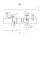
- FIG. 2 is a plan view of the embankment material manufacturing system 1. As shown in FIG. 2, the embankment material manufacturing system 1 selects a necessary amount of the A-type embankment material and the B-type embankment material used for reclamation of each landfill section in parallel with the reclamation of each landfill section. System unit 4 as a minimum configuration for manufacturing the system.
- the system unit 4 includes a kneading tank 5 that is also used for alternative production of A-type embankment material and B-type embankment material, A-type temporary storage place 6 where A-type waste is carried and temporarily placed, and B-type A B-type temporary storage place 7 into which waste is carried and temporarily placed, and a cement silo 8 that pneumatically feeds cement to the kneading tank 5 are provided.
- ⁇ Class A waste is a waste having a particle size or a hazardous substance concentration of a predetermined standard or less among inorganic wastes.
- the B-type waste is a waste having a particle size or a harmful substance concentration exceeding the predetermined standard among the inorganic wastes.
- Hazardous substances include radioactive substances as well as hazardous substances and heavy metals contained in incineration ash of general waste such as garbage and waste plastic.
- Class A waste and Class B waste the smaller grain waste and the larger grain waste separated by a sizing machine such as Trommel, and the amount of radioactivity per kilogram This is applicable to wastes having a value of 100 becquerel or less and wastes exceeding this.
- a sizing machine such as Trommel
- the Class A inorganic waste is a waste having various harmful substance concentrations that are each equal to or lower than a predetermined reference value, but is simpler than the Class B inorganic waste (regardless of the reference value).
- waste with a low concentration of harmful substances may be used.
- the kneading tank 5, the A-type temporary storage place 6, and the B-type temporary storage place 7 form a unidirectional arrangement in which the kneading tank 5 is disposed between the A-type temporary storage place 6 and the B-type temporary storage place 7.
- a cement silo 8 is disposed at a position corresponding to the kneading tank 5.
- there is an operating space 13 for operating heavy equipment such as a hydraulic excavator 10 with a bucket 9 and a hydraulic excavator 10 with a mixer 11, a dump truck 12, and the like.
- the loading of the A type waste or the B type waste into the A type temporary storage 6 or the B type temporary storage 7 can be performed using the dump truck 12.
- the transfer of the A type waste or the B type waste from the A type temporary storage site 6 or the B type temporary storage site 7 to the kneading tank 5 can be performed using a hydraulic excavator 10 with a bucket 9.
- kneading in the kneading tank 5 can be performed using a hydraulic excavator 10 with a mixer 11.
- the transfer of the type A embankment material or the type B embankment material from the kneading tank 5 to the landfill section 3 (see FIG. 1) during landfilling can be performed using a hydraulic excavator 10 with a bucket 9 and a dump truck 12.
- the system unit 4 includes a water tank 14 for storing water to be supplied to the kneading tank 5, a storage tank 15 for storing water for equipment cleaning, and a storage 16 for storing heavy metal fixing agents.
- the storage tank 15 may be used for storing a water-soluble or water-dispersible heavy metal fixing agent. Or you may add the storage tank for that separately.
- the water tank 14 and the storage 16 are installed on the one side of the arrangement formed by the kneading tank 5, the A-type temporary storage place 6, and the B-type temporary storage place 7.
- the storage tank 15 is disposed between the kneading tank 5 and the A-type temporary storage place 6. Instead of this, the storage tank 15 may be disposed between the kneading tank 5 and the B-type temporary storage place 7. Accordingly, the other side of the array can be applied to the above-described working space 13 that extends along the array.
- system unit 4 may be provided with a temporary sand storage 17 adjacent to the B-type temporary storage 7 and the like.
- This sand can be used, for example, when preparing a mortar for a coating layer provided on a compacted body formed of embankment material in each landfill section 3 (see FIG. 1).
- the system unit 4 may include a receiving hopper 18 that can be used when the cement is supplied from the cement silo 8 to the kneading tank 5.
- the receiving hopper 18 is disposed at the cement supply position in the kneading tank 5, and the cement is air-fed into the interior, and then retracted, whereby the cement can be supplied to the supply position.
- FIG. 3 is a plan view showing the embankment material manufacturing system according to the second embodiment.
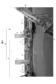
- FIG. 4 is a perspective view showing an image when a part of FIG. 3 is viewed from the working space side.
- this embankment material manufacturing system uses two system units 21 and 22 similar to the system unit 4 described above, and the A-type temporary storage place 6 is also used between the adjacent system units 21 and 22. To be arranged side by side.
- the embankment material manufacturing system 20 includes one A-type temporary storage place 6, two kneading tanks 5, and two B-type temporary storage places, and the A-type temporary storage place 6 exists on one side of each kneading tank 5.
- various heavy equipment such as a hydraulic excavator 10 and a dump truck 12 are operated from a position corresponding to one B-type temporary storage place 7 to a position corresponding to the other B-type temporary storage place 7.
- the working space 13 extends.
- the storage tank 15, the water tank 14, and the storage 16 are shared between the system units 4.
- FIG. 5 is a flowchart showing a process of manufacturing a banking material by the banking material manufacturing system 1 of FIG. 2 or the banking material manufacturing system 20 of FIGS. 3 and 4.
- step S ⁇ b> 1 the A type waste or the B type waste is transferred from the working space 13 side to the A type temporary storage place 6 or the B type temporary storage place 7 by the dump truck 12. Carry in and temporarily place (first step). This step is performed at any time according to the remaining amount of the A-type waste or the B-type waste in the A-type temporary storage 6 or the B-type temporary storage 7.
- step S2 the embankment material (hereinafter referred to as “target embankment material”) to be manufactured among the A-type embankment material or the B-type embankment material, and the kneading tank (hereinafter referred to as the target embankment material).
- target embankment material the embankment material to be manufactured among the A-type embankment material or the B-type embankment material
- the kneading tank hereinafter referred to as the target embankment material.
- “Used kneading tank”) is determined (second step).
- the determination of the target embankment material is performed in consideration of the A-type embankment material or the B-type embankment material required next in each landfill section 3 during reclamation. That is, in each landfill section 3, first, the B-type fill material is filled and compacted for each layer for a plurality of layers, and then the A-type fill material is filled and compacted for each layer for a plurality of layers. Landfill is performed at.
- the type of embankment material required according to the stage of the current landfill procedure in the landfill section 3 that is currently the object of landfill is determined as the target embankment material.
- a necessary type of embankment material is determined as the target embankment material according to the stage of the current landfill procedure in the landfill sections 3.
- the determination of the kneading tank to be used is made in consideration of the usage status of each kneading tank 5.
- the kneading tank 5 is determined to be the use kneading tank.
- the kneading tank 5 is determined to be the use kneading tank.
- step S3 an amount of cement suitable for the production of the target embankment material is supplied to the used kneading tank from the corresponding cement silo 8 by air pressure feeding (first operation). 3 steps).
- the cement is supplied by placing a receiving hopper 18 in which a corresponding air pressure hose 23 of a cement silo 8 is connected to a hose joint 18a at a supply position in the target kneading tank 5 (see FIG. 3).
- the cement is received from 8 and air-fed to the hopper 18, and then the receiving hopper 18 is retracted.
- the receiving hopper 18 is arranged and retracted by suspending the receiving hopper 18 with a crane.
- step S5 the type A waste or the type B waste used for manufacturing the target embankment material is supplied to the used kneading tank (fourth step).
- This supply is performed from the A-type temporary storage place 6 or the B-type temporary storage place 7 closest to the used kneading tank. Further, this supply can be performed by transferring A-type waste or B-type waste from the A-type temporary storage place 6 or the B-type temporary storage place 7 using the hydraulic excavator 10 equipped with the bucket 9.
- step S5 a necessary amount of water is supplied to the used kneading tank (fifth step). For this supply, water stored in the water tank 14 is used.
- step S6 a necessary amount of heavy metal fixing agent is supplied to the used kneading tank (sixth step).
- a powdery heavy metal fixing agent stored in the storage 16 is used.
- a water-soluble or water-dispersible heavy metal fixing agent may be stored in the storage tank 15 and used.
- step S7 the cement, type A waste or type B waste, and a necessary amount of water or heavy metal fixing agent supplied to the used kneading tank are kneaded (seventh step).
- This kneading is performed by a hydraulic excavator 10 with a mixer 11 disposed in the working space 13.
- the 1st class A embankment material or B class embankment material supplied to the landfill division 3 is obtained.
- step S8 the A-type banking material or the B-type banking material obtained by the kneading is transferred to the landfill section 3 being landfilled (eighth step).
- This transfer is performed by a hydraulic excavator 10 with a bucket 9 and a dump truck 12 arranged in the working space 13. That is, it is carried out by loading the A-type banking material or the B-type banking material in the used kneading tank on the dump truck 12 by the hydraulic excavator 10, carrying the dump truck 12 to the landfill section 3, and discharging it into the landfill section 3.
- the type A embankment material and the type B embankment material which are transferred to the landfill section 3 and used for the landfill are formed into a compacted body at the time of the landfill, and further solidified after a curing period. Thereby, the A type banking material and the B type banking material are regenerated as the ground, and the final disposal is completed.
- the supply of the A-type waste or the B-type waste from the A-type temporary storage 6 or the B-type temporary storage 7 to the kneading tank 5 is performed by the heavy machinery on the working space 13 through the shortest path
- the kneading tank 5 is also used for kneading A-type waste or B-type waste and cement, etc.
- the operation space 13 is used to carry in, supply, knead, transfer of embankment materials, etc. Is carried out without hindrance.
- the A-type banking material and the B-type banking material are used in accordance with the landfill stage in each landfill section 3 while effectively using the limited space in the final disposal site 2 for the A-type banking material and the B-type banking material.
- the materials can be manufactured sequentially and efficiently.
- the system unit 4 is installed on one side of the arrangement formed by the type A temporary storage place 6, the kneading tank 5 and the type B temporary storage place 7, and a water tank 14 for storing water to be supplied to the kneading tank 5,
- the storage tank 15 is installed between the tank 5 and the A-type temporary storage place 6 or the B-type temporary storage place 7 and stores equipment cleaning water or a water-soluble or water-dispersible heavy metal fixing agent. For this reason, water or this heavy metal fixing agent can be immediately supplied to the kneading tank 5 as needed. Further, the bucket 9 and the mixer 11 of the excavator 10 located in the working space 13 can be cleaned as appropriate.
- each system is provided.
- the kneading tanks 5 of the units 21 and 22 in parallel, more A type banking material or B type banking material can be efficiently manufactured while using the space in the final disposal site 2 more effectively. Can do.
- the kneading tanks of the system units 21 and 22 are appropriately distributed and used for the production of the A-type banking material or the B-type banking material.
- the type A banking material or the type B banking material required by the section 3 can be efficiently manufactured and supplied.
- the determination of the target embankment material and the used kneading tank is made each time according to the use status of each kneading tank and the type of embankment material required. For this reason, the manufacture of the A-type banking material or the B-type banking material for landfilling in each landfill section can be efficiently performed in accordance with the progress of landfilling in each landfill section.
- the supply of the A-type banking material, the B-type banking material, and the cement to each kneading tank is performed from the A-type temporary storage place 6 or the B-type temporary storage place 7 and the cement silo 8 in the vicinity of each kneading tank 5.
- the operation space 13 is used by a heavy machine or the like on the operation space 13 extending to the other side of the arrangement formed by the seed temporary storage place 6, the kneading tank 5, and the B type temporary storage place 7.
- the production of the A-type banking material and the B-type banking material can be efficiently performed while effectively utilizing the limited space in the final disposal site 2.
- the present invention is not limited to the above-described embodiment.
- the embankment material manufacturing system 20 including the two system units 21 and 22 is shown, but instead of this, the embankment material manufacturing system includes three or more system units between the adjacent system units. You may arrange in one direction so that the storage place 6 or the B type temporary storage place 7 may be shared.
Landscapes
- Engineering & Computer Science (AREA)
- Environmental & Geological Engineering (AREA)
- Processing Of Solid Wastes (AREA)
Abstract
最終処分場における限られたスペース内で盛土材を効率的に製造できる盛土材製造システムを提供する。 盛土材製造システムは、最終処分場2の各埋立区画3の埋立て用のA種盛土材及びB種盛土材を製造するためのシステムユニット4を有する。システムユニット4は、混練槽5と、A種廃棄物のA種仮置き場6と、B種廃棄物のB種仮置き場7と、混練槽5にセメントをエア圧送するセメントサイロ8とを備える。A種仮置き場6、混練槽5及びB種仮置き場7は、この順で配置した一方向の配列を形成しており、配列の一方の側方にはセメントサイロ、他方の側方には重機10又はダンプカー12の稼動スペース13を備える。
Description
本発明は、廃棄物の最終処分場において、地盤を取り除いて設定された多数の埋立区画の埋立てに使用される盛土材を製造するための盛土材製造システム及び盛土材製造方法に関する。
従来、この種の盛土材製造方法として、無機廃棄物を粒の大きな高密度廃棄物と粒の小さな低密度廃棄物とに分け、それぞれを材料として2種の盛土材を製造する方法が知られている(特許文献1参照)。2種の盛土材は、廃棄物の最終処分場において予め地盤を取り除いて水平方向及び垂直方向に多数設定された各埋立区画において、異なる2つの空間に配置されて圧密成形され、処分される。
盛土材の製造に際しては、最終処分場に設置されたセメントサイロと混練槽が用いられる。すなわち、混練槽に、盛土材の材料として、セメントサイロから所定量のセメントを投入し、さらに所定量の高密度廃棄物をバックホーにより投入し、必要に応じて水を加える。そして、これらの材料をバックホーのアーム先端に装着した撹拌機で混練することにより、高密度廃棄物を原料とする盛土材を得ることができる。
低密度廃棄物を原料とする盛土材も同様にして得られる。2種の盛土材は、各埋立区画について、数回に分けて製造される。製造される高密度廃棄物の盛土材は、埋立区画内の2つの空間のうちの一方に順次充填され、圧密低密度廃棄物の盛土材は他方の空間に順次配置される。埋立区画に充填された盛土材は、締め固められ、一定の養生期間を経て固化する。このようにして、廃棄物は、地盤の再生に用いられ、処分される。
上述の2種の盛土材の製造及び埋立区画への充填は、最終処分場の多数の埋立区画について、かつ埋立区画毎に数回例えば5回に分けて繰り返し行われる。このため、2種の盛土材の製造は、極力効率的に行う必要がある。
また、最終処分場では各埋立区画における盛土材の充填や締固め、養生等の作業が行われており、そのための各種重機や、盛土材、廃棄物、各種資材等の搬送用のトラック等も存在するので、限られた最終処分場内のスペースを有効に使って盛土材の製造を行う必要がある。
本発明の目的は、かかる従来技術の課題に鑑み、最終処分場における限られたスペース内で盛土材を効率的に製造できる盛土材製造システム及び盛土材製造方法を提供することにある。
第1発明の盛土材製造システムは、廃棄物の最終処分場において、地盤を取り除いて多数設定された各埋立区画の埋立てに使用されるA種盛土材及びB種盛土材を、各埋立区画の埋立てと並行して所定量ずつ択一的に製造するためのシステムユニットを有する盛土材製造システムであって、前記A種盛土材は、粒の大きさ若しくは有害物質濃度が所定基準以下であるA種廃棄物、セメント、及び必要量の水又は重金属固定剤を混練して得られ、前記B種盛土材は、粒の大きさ又は有害物質濃度が該所定基準を超えるB種廃棄物、セメント、及び必要量の水又は重金属固定剤を混練して得られるものであり、前記システムユニットは、前記A種盛土材及びB種盛土材の択一的な製造に兼用される混練槽と、前記A種廃棄物が搬入されて仮置きされるA種仮置き場と、前記B種廃棄物が搬入されて仮置きされるB種仮置き場と、前記混練槽にセメントをエア圧送するセメントサイロとを備え、前記混練槽、A種仮置き場及びB種仮置き場は、該混練層を該A種仮置き場と該B種仮置き場との間に配置した一方向の配列を形成しており、前記配列の一方の側方には、前記セメントサイロが、前記混練槽に対応する位置に配置され、前記配列の他方の側方には、前記A種仮置き場又はB種仮置き場への前記A種廃棄物又はB種廃棄物の搬入、該A種仮置き場又はB種仮置き場からの該混練槽への該A種廃棄物又はB種廃棄物の移送、該混練槽における混練、及び該混練槽からの前記A種盛土材又はB種盛土材の搬出を行う重機又はダンプカーの稼動スペースを備えることを特徴とする。
第1発明によれば、各埋立区画を順次埋め立てる際に、各埋立区画毎にA種盛土材及びB種盛土材が使用される。このため、各埋立区画における各埋立段階で必要なA種盛土材又はB種盛土材が択一的に製造される。
A種盛土材の製造に際しては、混練槽に対し、その一方の側に位置するA種仮置き場からA種廃棄物が混練槽に供給される。必要量のセメントは、A種仮置き場、混練槽及びB種仮置き場が形成する配列の一方の側方のセメントサイロから供給される。
このとき、A種仮置き場から混練槽へのA種廃棄物の供給は、該配列の他方の側方に位置する稼働スペースに配置された重機例えばバケット付きの油圧ショベルで行うことができる。なお、A種仮置き場へのA種廃棄物の予めの仮置きは、ダンプカー等により稼働スペース側からA種廃棄物をA種仮置き場へ搬入することにより行うことができる。
混練槽に供給されたA種廃棄物やセメントの混練は、稼働スペースに配置されたミキサ付きの油圧ショベルにより行うことができる。また、混練により得られたA種盛土材の埋立区画への移送は、稼働スペース側から、バケット付きパワーショベルやダンプカーにより行うことができる。
B種盛土材の製造に際しても、A種廃棄物の場合と同様にして、B種仮置き場へのB種廃棄物の搬入、B種廃棄物の混練槽への供給、混練槽における混練、及びB種盛土材の埋立区画への移送が行われる。
これによれば、A種仮置き場又はB種仮置き場から混練槽へのA種廃棄物又はB種廃棄物の供給が、稼働スペース上の重機により最短経路で行われ、A種廃棄物又はB種廃棄物とセメント等の混練に混練槽が兼用され、かつ稼働スペースを利用して、ダンプカーや重機による廃棄物の搬入や、供給、混練、盛土材の移送等が支障なく行われる。
したがって、A種盛土材及びB種盛土材を、限られた最終処分場内のスペースを有効に活用しながら、各埋立区画における埋立段階に応じ、必要なA種盛土材又はB種盛土材を順次選択して効率的に製造することができる。
第2発明の盛土材製造システムは、第1発明において、前記システムユニットは、前記配列の前記一方の側方に設置され、前記混練槽に供給する水を貯留する水槽と、前記混練槽と前記A種仮置き場又はB種仮置き場との間に設置され、機器洗浄用の水又は水溶性若しくは水分散性の重金属固定剤を貯留する貯留槽とを備えることを特徴とする。
これによれば、水又は水溶性若しくは水分散性の重金属固定剤を、必要に応じて直ちに混練槽に供給することができる。また、貯留槽に機器洗浄用の水を貯留しておくことにより、稼動スペースに位置する重機のバケットやミキサ等を適宜洗浄することができる。
第3発明の盛土材製造システムは、第1又は第2発明において、複数の前記システムユニットを、隣接するシステムユニット間で前記A種仮置き場又はB種仮置き場が兼用されるように、前記一方向に並べて備えることを特徴とする。
第3発明によれば、各システムユニットの混練槽においても、その両側にA種仮置き場及びB種仮置き場が存在し、その対応位置にセメントサイロが存在する。また、全システムユニットが形成する配列のセメントサイロと反対側には、該配列に沿って延在する稼働スペースが存在する。また、A種仮置き場又はB種仮置き場が、隣接するシステムユニット間で兼用される。
このため、各システムユニットの混練槽を並行して用いることにより、最終処分場内のスペースをより有効に活用しながら、より多くのA種盛土材又はB種盛土材を効率的に供給することができる。
また、複数の埋立区画を並行して埋め立てる場合には、各システムユニットの混練槽をA種盛土材又はB種盛土材の製造に適宜振り分けて用いることにより、各埋立中の埋立区画が要求するA種盛土材又はB種盛土材を、効率的に製造して供給することができる。
第4発明の盛土材製造方法は、廃棄物の最終処分場において、地盤を取り除いて設定された多数の埋立区画の埋立てに使用されるA種盛土材及びB種盛土材を、各埋立区画の埋立てと並行して製造する製造工程を、所定の盛土材製造システムを用いて行う盛土材製造方法であって、前記A種盛土材は、粒の大きさ若しくは有害物質濃度が所定基準以下であるA種廃棄物、セメント、及び必要量の水又は重金属固定剤を混練して得られ、前記B種盛土材は、粒の大きさ又は有害物質濃度が該所定基準を超えるB種廃棄物、セメント、及び必要量の水又は重金属固定剤を混練して得られるものであり、前記盛土材製造システムは、1又は複数の前記A種廃棄物のA種仮置き場、前記混練を行うための混練槽、及び前記B種廃棄物のB種仮置き場を、各混練槽の一方の側に該A種仮置き場が存在して他方の側にB種仮置き場が存在し、かつ該混練槽と該A種仮置き場又はB種仮置き場とが交互となるように一方向に配置した配列と、該配列の一方の側方における各混練槽に対応する位置に配置したセメントサイロと、該配列の他方の側方に延在する各種重機及びダンプカーの稼働スペースとを備えるものであり、前記製造工程は、各A種仮置き場又はB種仮置き場に前記A種廃棄物又はB種廃棄物をダンプカーにより前記稼働スペース側から搬入して仮置きする第1工程と、前記A種盛土材又はB種盛土材のうちの製造対象となる対象盛土材、及び該対象盛土材の製造に使用する使用混練槽を、各混練槽の使用状況、並びに埋立て中の各埋立区画において次に必要とされる前記A種盛土材又はB種盛土材を考慮して決定する第2工程と、前記第2工程の後、前記対象盛土材の製造に適した量のセメントを、前記使用混練槽に対し、対応する前記セメントサイロからエア圧送する第3工程と、前記第2工程の後、前記対象盛土材の製造に使用する前記A種廃棄物又はB種廃棄物を、前記使用混練槽に対し、最も近い前記A種仮置き場又はB種仮置き場から、前記稼働スペースに配置されたバケット付き油圧ショベルにより供給する第4工程と、前記第2工程の後、前記使用混練槽に対し、必要量の水を前記配列の一方の側方に配置された水槽から供給する第5工程と、前記第2工程の後、前記使用混練槽に対し、必要量の重金属固定剤を、前記配列の一方の側方に配置された保管庫又は該使用混練槽の前記一方向における隣に配置された貯留槽から供給する第6工程と、前記第3~第6工程の後、前記稼働スペースに配置されたミキサ付きの油圧ショベルにより、前記使用混練槽に係る混練を行う第6工程と、前記第6工程の後、得られたA種盛土材又はB種盛土材を、前記稼働スペースに配置されたバケット付き油圧ショベル及びダンプカーにより、対象とする前記埋立区画に移送する第7工程とを備えることを特徴とする。
第4発明によれば、製造対象とする対象盛土材及び使用する使用混練槽の決定は、その都度、各混練槽の使用状況、並びに必要とされる盛土材の種類に応じて行われる。このため、各埋立区画における埋立のためのA種盛土材又はB種盛土材の製造を、各埋立区画における埋立の進捗状況に合わせて、過不足なく効率的に行うことができる。
また、各混練槽へのA種盛土材又はB種盛土材や、セメントの供給は、各混練槽の近傍のA種仮置き場又はB種仮置き場やセメントサイロから行われる。また、A種仮置き場又はB種仮置き場への廃棄物の搬送や、各混練槽への廃棄物の供給、各混練槽での混練、得られた盛土材の移送は、A種仮置き場、混練槽及びB種仮置き場で形成される配列の他方の側方に沿った稼働スペース上の重機等により、稼働スペースを利用して行われる。
したがって、A種盛土材及びB種盛土材の製造を、最終処分場内の限られたスペースを有効に活用しながら、効率的に行うことができる。
以下、図面を用いて本発明の実施形態を説明する。図1は、第1実施形態に係る盛土材製造システムが適用された廃棄物の最終処分場における埋立領域の平面図である。図1に示すように、この盛土材製造システム1は、最終処分場2の埋立領域において、無機廃棄物を材料として盛土材を製造するために用いられる。
最終処分場2の埋立領域では、予め地盤を取り除いて確保した埋立て用の空間内に多数の埋立区画3が、水平方向及び垂直方向に区分されて設定される。1つの埋立区画3は、例えば長さが8m、幅が6.8m、高さが1.3mで、高さ方向が鉛直方向に一致した直方体の形状を有する。
鉛直方向の埋立区画3の区分数は、例えば15である。したがって、最終処分場2には、水平方向に碁盤の目状に区分され、かつ例えば15層に積み重ねられた多数の埋立区画3が存在する。
盛土材製造システム1による盛土材の製造は、1つの埋立区画3について複数回行われる。盛土材は、各埋立区画3に対し、順次供給され、固化されて、地盤の再生に供される。かかる埋立区画3の埋立は、下方の層に属する埋立区画3から行われる。同じ層では、順次隣接する埋立区画3に対して埋立てが行われてゆく。
図2は、盛土材製造システム1の平面図である。図2に示すように、盛土材製造システム1は、各埋立区画の埋立てに使用されるA種盛土材及びB種盛土材を、各埋立区画の埋立てと並行して必要量ずつ択一的に製造するための最小限の構成としてのシステムユニット4を有する。
システムユニット4は、A種盛土材及びB種盛土材の択一的な製造に兼用される混練槽5と、A種廃棄物が搬入されて仮置きされるA種仮置き場6と、B種廃棄物が搬入されて仮置きされるB種仮置き場7と、混練槽5にセメントをエア圧送するセメントサイロ8とを備える。
A種廃棄物は、無機廃棄物のうち、粒の大きさ若しくは有害物質濃度が所定基準以下の廃棄物である。B種廃棄物は、無機廃棄物のうち、粒の大きさ若しくは有害物質濃度が前記所定基準を超える廃棄物である。有害物質には、生ごみや廃プラスチック等のような一般廃棄物の焼却灰に含有される有害物質や重金属のほか、放射性物質が含まれる。
具体的には、A種廃棄物及びB種廃棄物としては、トロンメル等の分粒機で分流された粒の小さい方の廃棄物及び粒の大きい方の廃棄物や、1キログラム当たりの放射能量が100ベクレル以下である廃棄物及びこれを超える廃棄物が該当する。ここで、複数の基準のうち1つの基準でも超える場合には、B種廃棄物に分類される。
なお、本実施形態において、A種無機廃棄物は、種々の有害物質濃度がそれぞれ所定の基準値以下である廃棄物であるが、(基準値に拘らず)B種無機廃棄物に対して単純に有害物質濃度が低い廃棄物としてもよい。
混練槽5、A種仮置き場6及びB種仮置き場7は、混練槽5をA種仮置き場6とB種仮置き場7との間に配置した一方向の配列を形成している。該配列の一方の側方には、セメントサイロ8が、混練槽5に対応する位置に配置される。該配列の他方の側方には、バケット9付きの油圧ショベル10や、ミキサ11付きの油圧ショベル10等の重機、ダンプカー12等が稼働するための稼働スペース13を備える。
A種仮置き場6又はB種仮置き場7へのA種廃棄物又はB種廃棄物の搬入は、ダンプカー12を用いて行うことができる。A種仮置き場6又はB種仮置き場7からの混練槽5へのA種廃棄物又はB種廃棄物の移送は、バケット9付きの油圧ショベル10を用いて行うことができる。
また、混練槽5における混練は、ミキサ11付きの油圧ショベル10を用いて行うことができる。混練槽5から埋立中の埋立区画3(図1参照)へのA種盛土材又はB種盛土材の移送は、バケット9付きの油圧ショベル10及びダンプカー12を用いて行うことができる。
また、システムユニット4は、混練槽5に供給する水を貯留する水槽14と、機器洗浄用の水を貯留する貯留槽15と、重金属固定剤を保管する保管庫16とを備える。貯留槽15は、水溶性若しくは水分散性の重金属固定剤を貯留するために用いてもよい。又はそのための貯留槽を別途追加してもよい。
水槽14及び保管庫16は、上述の混練槽5、A種仮置き場6及びB種仮置き場7により形成される配列の前記一方の側方に設置される。貯留槽15は、混練槽5とA種仮置き場6との間に配置される。この代わりに、貯留槽15を、混練槽5とB種仮置き場7との間に配置してもよい。したがって、該配列の他方の側方は、すべて該配列に沿って延在する上述の稼働スペース13に当てることができる。
また、システムユニット4は、B種仮置き場7等に隣接させて砂の仮置き場17を備えてもよい。この砂は、例えば各埋立区画3(図1参照)において盛土材で形成される圧密成形体上に設けられる被覆層用のモルタルを調製するときに用いることができる。
また、システムユニット4は、セメントサイロ8からセメントを混練槽5に供給するときに用いることができる受けホッパ18を備えてもよい。受けホッパ18を、混練槽5内のセメントの供給位置に配置してその内部にセメントをエア圧送した後、退避させることにより、該供給位置にセメントを供給することができる。
図3は、第2実施形態に係る盛土材製造システムを示す平面図である。図4は、図3の一部を稼働スペース側から見たときのイメージを示す斜視図である。図3及び図4に示すように、この盛土材製造システムは、上述のシステムユニット4と同様の2つのシステムユニット21及び22を、隣接するシステムユニット21及び22間でA種仮置き場6が兼用されるように並べて備える。
すなわち、この盛土材製造システム20は、1つのA種仮置き場6、2つの混練槽5、及び2つのB種仮置き場を、各混練槽5の一方の側にA種仮置き場6が存在して他方の側にB種仮置き場7が存在し、かつ混練槽5とA種仮置き場6又はB種仮置き場7とが交互となるように一方向に配置した配列と、該配列の一方の側方における各混練槽5に対応する位置にそれぞれ配置した2つのセメントサイロ8とを備える。
該配列の他方の側方には、一方のB種仮置き場7に対応する位置から他方のB種仮置き場7に対応する位置にわたり、油圧ショベル10等の各種重機やダンプカー12が稼働するための稼働スペース13が延在する。なお、貯留槽15、水槽14及び保管庫16は、各システムユニット4間で兼用される。
図5は、図2の盛土材製造システム1、又は図3及び図4の盛土材製造システム20により盛土材を製造する工程を示すフローチャートである。図5に示すように、盛土材の製造に際しては、まず、ステップS1において、A種廃棄物又はB種廃棄物をダンプカー12により稼働スペース13側からA種仮置き場6又はB種仮置き場7に搬入して仮置きする(第1工程)。この工程は、A種仮置き場6又はB種仮置き場7におけるA種廃棄物又はB種廃棄物の残存量に応じ、随時行われる。
次に、ステップS2において、A種盛土材又はB種盛土材のうちの製造対象となる盛土材(以下、「対象盛土材」という。)、及び対象盛土材の製造に使用する混練槽(以下、「使用混練槽」という。)を決定する(第2工程)。
対象盛土材の決定は、埋立て中の各埋立区画3において次に必要とされるA種盛土材又はB種盛土材を考慮して行われる。すなわち、各埋立区画3においては、まず、B種盛土材を複数層について層毎に充填及び締固めを行い、その後、A種盛土材を複数層について層毎に充填及び締固めを行うという手順で埋立てが行われる。
したがって、例えば、現在埋立の対象となっている埋立区画3における現時点での埋立手順の段階に応じて必要とされる種類の盛土材が対象盛土材に決定される。複数の埋立区画3を並行して埋め立てている場合には、それら埋立区画3における現時点での埋立手順の段階に応じて必要な種類の盛土材が対象盛土材に決定される。
使用混練槽の決定は、各混練槽5の使用状況を考慮して行われる。図2の盛土材製造システム1のように混練槽5が1つしかない場合には、その混練槽5が使用混練槽に決定される。図3の盛土材製造システム20の場合のように、混練槽5が複数存在する場合には、例えば、2つの混練槽5のうち、空いている混練槽5があれば、その混練槽5が使用混練槽に決定される。空いている混練槽5がなければ、その後、最も早く空き状態となる混練槽5が使用混練槽に決定される。
対象盛土材及び使用混練槽が決まると、次に、ステップS3において、対象盛土材の製造に適した量のセメントを、使用混練槽に対し、対応するセメントサイロ8からエア圧送により供給する(第3工程)。
このセメントの供給は、対応するセメントサイロ8のエア圧送用のホース23をホースジョイント18aに接続した受けホッパ18を、対象混練槽5内の供給位置に配置し(図3参照)、そのセメントサイロ8からセメントを受けホッパ18にエア圧送し、その後、受けホッパ18を退避させることにより行われる。受けホッパ18の配置及び退避は、クレーンで受けホッパ18を吊り下げることにより行われる。
次に、ステップS5において、対象盛土材の製造に使用するA種廃棄物又はB種廃棄物を、使用混練槽に供給する(第4工程)。この供給は、使用混練槽に最も近いA種仮置き場6又はB種仮置き場7から行う。また、この供給は、バケット9を装備した油圧ショベル10を用いてA種仮置き場6又はB種仮置き場7からA種廃棄物又はB種廃棄物を移送することにより行うことができる。
次に、ステップS5において、使用混練槽に必要量の水を供給する(第5工程)。この供給には、水槽14に貯留された水が用いられる。
次に、ステップS6において、使用混練槽に必要量の重金属固定剤を供給する(第6工程)。この供給には、保管庫16内に保管された粉末状の重金属固定剤が用いられる。この代わりに、貯留槽15に水溶性又は水分散性の重金属固定剤を貯留しておき、これを用いてもよい。
次に、ステップS7において、使用混練槽に供給されたセメント、A種廃棄物又はB種廃棄物、及び必要量の水又は重金属固定剤を混練する(第7工程)。この混練は、稼働スペース13に配置されたミキサ11付きの油圧ショベル10により行われる。これにより、埋立区画3に供給する1回分のA種盛土材又はB種盛土材が得られる。
次に、ステップS8において、前記混練により得られたA種盛土材又はB種盛土材を、埋立て中の埋立区画3に移送する(第8工程)。この移送は、稼働スペース13に配置されたバケット9付き油圧ショベル10及びダンプカー12によって行われる。すなわち、使用混練槽内のA種盛土材又はB種盛土材を油圧ショベル10によりダンプカー12に積載し、ダンプカー12で当該埋立区画3まで運び、当該埋立区画3内に排出することにより行われる。
埋立区画3に移送され、その埋立てに使用されるA種盛土材及びB種盛土材は、その埋立て時に圧密成形体に形成され、さらに養生期間を経て固化される。これにより、そのA種盛土材及びB種盛土材は、地盤として再生され、最終処分が完了する。
本実施形態によれば、A種仮置き場6又はB種仮置き場7から混練槽5へのA種廃棄物又はB種廃棄物の供給が、稼働スペース13上の重機により最短経路で行われ、A種廃棄物又はB種廃棄物とセメント等の混練に混練槽5が兼用され、かつ稼働スペース13を利用して、ダンプカーや重機による廃棄物の搬入や、供給、混練、盛土材の移送等が支障なく行われる。
したがって、A種盛土材及びB種盛土材を、限られた最終処分場2内のスペースを有効に活用しながら、各埋立区画3における埋立段階に応じ、必要なA種盛土材又はB種盛土材を順次効率的に製造することができる。
また、システムユニット4は、A種仮置き場6、混練槽5及びB種仮置き場7が形成する配列の一方の側方に設置され、混練槽5に供給する水を貯留する水槽14と、混練槽5とA種仮置き場6又はB種仮置き場7との間に設置され、機器洗浄用の水又は水溶性若しくは水分散性の重金属固定剤を貯留する貯留槽15とを備える。このため、水又は該重金属固定剤を、必要に応じて直ちに混練槽5に供給することができる。また、稼働スペース13に位置する油圧ショベル10のバケット9やミキサ11等を適宜洗浄することができる。
また、図3の盛土材製造システム20の場合のように、システムユニット21及び22を、これらの間でA種仮置き場6が兼用されるように、一方向に並べて備える場合には、各システムユニット21及び22の混練槽5を並行して用いることにより、最終処分場2内のスペースをより有効に活用しながら、より多くのA種盛土材又はB種盛土材を効率的に製造することができる。
また、複数の埋立区画3を並行して埋め立てる場合には、各システムユニット21及び22の混練槽をA種盛土材又はB種盛土材の製造に適宜振り分けて用いることにより、各埋立中の埋立区画3が要求するA種盛土材又はB種盛土材を、効率的に製造して供給することができる。
また、対象盛土材及び使用混練槽の決定は、その都度、各混練槽の使用状況、並びに必要とされる盛土材の種類に応じて行われる。このため、各埋立区画における埋立のためのA種盛土材又はB種盛土材の製造を、各埋立区画における埋立の進捗状況に合わせて、過不足なく効率的に行うことができる。
また、各混練槽へのA種盛土材又はB種盛土材や、セメントの供給は、各混練槽5の近傍のA種仮置き場6又はB種仮置き場7やセメントサイロ8から行われる。また、A種仮置き場6又はB種仮置き場7への廃棄物の搬送や、各混練槽5への廃棄物の供給、各混練槽5での混練、得られた盛土材の移送は、A種仮置き場6、混練槽5及びB種仮置き場7で形成される配列の他方の側方に延在する稼働スペース13上の重機等により、稼働スペース13を利用して行われる。
したがって、A種盛土材及びB種盛土材の製造を、最終処分場2内の限られたスペースを有効に活用しながら、効率的に行うことができる。
なお、本発明は上述の実施形態に限定されない。例えば、図3では2つのシステムユニット21及び22を備える盛土材製造システム20を示したが、この代わりに、盛土材製造システムは、3以上のシステムユニッを、隣接するシステムユニット間でA種仮置き場6又はB種仮置き場7が兼用されるように、一方向に並べて備えてもよい。
1、20…盛土材製造システム、2…最終処分場、3…埋立区画、4、21、22…システムユニット、5…混練槽、6…A種仮置き場、7…B種仮置き場、8…セメントサイロ、12…ダンプカー、13…稼動スペース、14…水槽、15…貯留槽。
Claims (4)
- 廃棄物の最終処分場において、地盤を取り除いて多数設定された各埋立区画の埋立てに使用されるA種盛土材及びB種盛土材を、各埋立区画の埋立てと並行して必要量ずつ択一的に製造するためのシステムユニットを有する盛土材製造システムであって、
前記A種盛土材は、粒の大きさ若しくは有害物質濃度が所定基準以下であるA種廃棄物、セメント、及び必要量の水又は重金属固定剤を混練して得られ、前記B種盛土材は、粒の大きさ又は有害物質濃度が該所定基準を超えるB種廃棄物、セメント、及び必要量の水又は重金属固定剤を混練して得られるものであり、
前記システムユニットは、
前記A種盛土材及びB種盛土材の択一的な製造に兼用される混練槽と、
前記A種廃棄物が搬入されて仮置きされるA種仮置き場と、
前記B種廃棄物が搬入されて仮置きされるB種仮置き場と、
前記混練槽にセメントをエア圧送するセメントサイロとを備え、
前記混練槽、A種仮置き場及びB種仮置き場は、該混練層を該A種仮置き場と該B種仮置き場との間に配置した一方向の配列を形成しており、
前記配列の一方の側方には、前記セメントサイロが、前記混練槽に対応する位置に配置され、
前記配列の他方の側方には、前記A種仮置き場又はB種仮置き場への前記A種廃棄物又はB種廃棄物の搬入、該A種仮置き場又はB種仮置き場からの該混練槽への該A種廃棄物又はB種廃棄物の移送、該混練槽における混練、及び該混練槽からの前記A種盛土材又はB種盛土材の搬出を行う重機又はダンプカーの稼動スペースを備えることを特徴とする盛土材製造システム。 - 前記システムユニットは、
前記配列の前記一方の側方に設置され、前記混練槽に供給する水を貯留する水槽と、
前記混練槽と前記A種仮置き場又はB種仮置き場との間に設置され、機器洗浄用の水又は水溶性若しくは水分散性の重金属固定剤を貯留する貯留槽とを備えることを特徴とする請求項1に記載の盛土材製造システム。 - 複数の前記システムユニットを、隣接するシステムユニット間で前記A種仮置き場又はB種仮置き場が兼用されるように、前記一方向に並べて備えることを特徴とする請求項1又は2に記載の盛土材製造システム。
- 廃棄物の最終処分場において、地盤を取り除いて設定された多数の埋立区画の埋立てに使用されるA種盛土材及びB種盛土材を、各埋立区画の埋立てと並行して製造する製造工程を、所定の盛土材製造システムを用いて行う盛土材製造方法であって、
前記A種盛土材は、粒の大きさ若しくは有害物質濃度が所定基準以下であるA種廃棄物、セメント、及び必要量の水又は重金属固定剤を混練して得られ、前記B種盛土材は、粒の大きさ又は有害物質濃度が該所定基準を超えるB種廃棄物、セメント、及び必要量の水又は重金属固定剤を混練して得られるものであり、
前記盛土材製造システムは、1又は複数の前記A種廃棄物のA種仮置き場、前記混練を行うための混練槽、及び前記B種廃棄物のB種仮置き場を、各混練槽の一方の側に該A種仮置き場が存在して他方の側にB種仮置き場が存在し、かつ該混練槽と該A種仮置き場又はB種仮置き場とが交互となるように一方向に配置した配列と、該配列の一方の側方における各混練槽に対応する位置に配置したセメントサイロと、該配列の他方の側方に延在する各種重機及びダンプカーの稼働スペースとを備えるものであり、
前記製造工程は、
各A種仮置き場又はB種仮置き場に前記A種廃棄物又はB種廃棄物をダンプカーにより前記稼働スペース側から搬入して仮置きする第1工程と、
前記A種盛土材又はB種盛土材のうちの製造対象となる対象盛土材、及び該対象盛土材の製造に使用する使用混練槽を、各混練槽の使用状況、並びに埋立て中の各埋立区画において次に必要とされる前記A種盛土材又はB種盛土材を考慮して決定する第2工程と、
前記第2工程の後、前記対象盛土材の製造に適した量のセメントを、前記使用混練槽に対し、対応する前記セメントサイロからエア圧送する第3工程と、
前記第2工程の後、前記対象盛土材の製造に使用する前記A種廃棄物又はB種廃棄物を、前記使用混練槽に対し、最も近い前記A種仮置き場又はB種仮置き場から、前記稼働スペースに配置されたバケット付き油圧ショベルにより供給する第4工程と、
前記第2工程の後、前記使用混練槽に対し、必要量の水を前記配列の一方の側方に配置された水槽から供給する第5工程と、
前記第2工程の後、前記使用混練槽に対し、必要量の重金属固定剤を、前記配列の一方の側方に配置された保管庫又は該使用混練槽の前記一方向における隣に配置された貯留槽から供給する第6工程と、
前記第3~第6工程の後、前記稼働スペースに配置されたミキサ付きの油圧ショベルにより、前記使用混練槽に係る混練を行う第7工程と、
前記第7工程の後、前記混練により得られたA種盛土材又はB種盛土材を、前記稼働スペースに配置されたバケット付き油圧ショベル及びダンプカーにより、対象とする前記埋立区画に移送する第8工程とを備えることを特徴とする盛土材製造方法。
Applications Claiming Priority (2)
| Application Number | Priority Date | Filing Date | Title |
|---|---|---|---|
| JP2012243198 | 2012-11-02 | ||
| JP2012-243198 | 2012-11-02 |
Publications (1)
| Publication Number | Publication Date |
|---|---|
| WO2014068796A1 true WO2014068796A1 (ja) | 2014-05-08 |
Family
ID=50626757
Family Applications (1)
| Application Number | Title | Priority Date | Filing Date |
|---|---|---|---|
| PCT/JP2012/082690 Ceased WO2014068796A1 (ja) | 2012-11-02 | 2012-12-17 | 盛土材製造システム及び盛土材製造方法 |
Country Status (1)
| Country | Link |
|---|---|
| WO (1) | WO2014068796A1 (ja) |
Citations (2)
| Publication number | Priority date | Publication date | Assignee | Title |
|---|---|---|---|---|
| JP2003117532A (ja) * | 2001-10-09 | 2003-04-22 | Taiheiyo Cement Corp | 重金属溶出抑制固化材及び固化方法 |
| JP2010207669A (ja) * | 2009-03-07 | 2010-09-24 | Fuji Corporation:Kk | 最終処分場における無機廃棄物分離・一体化による多数の単位固化物成形処分方法並びに多数の単位固化物成形処分構造体 |
-
2012
- 2012-12-17 WO PCT/JP2012/082690 patent/WO2014068796A1/ja not_active Ceased
Patent Citations (2)
| Publication number | Priority date | Publication date | Assignee | Title |
|---|---|---|---|---|
| JP2003117532A (ja) * | 2001-10-09 | 2003-04-22 | Taiheiyo Cement Corp | 重金属溶出抑制固化材及び固化方法 |
| JP2010207669A (ja) * | 2009-03-07 | 2010-09-24 | Fuji Corporation:Kk | 最終処分場における無機廃棄物分離・一体化による多数の単位固化物成形処分方法並びに多数の単位固化物成形処分構造体 |
Similar Documents
| Publication | Publication Date | Title |
|---|---|---|
| JP4317260B1 (ja) | 最終処分場における無機廃棄物分離・一体化による多数の単位固化物成形処分方法並びに多数の単位固化物成形処分構造体 | |
| JP2005314022A (ja) | 焼却飛灰積込みシステム | |
| JP3189765U (ja) | 埋立材製造システム | |
| JP3184974U (ja) | アタッチメント洗浄プール | |
| JPWO2015037249A1 (ja) | 土木工事改善方法及び改質用紙粉材料 | |
| JP6341818B2 (ja) | 遮水材の製造方法 | |
| JP5847394B2 (ja) | 処理対象物の処理方法と処理装置 | |
| JP3184977U (ja) | ダンプアッププール | |
| JP5389291B1 (ja) | 盛土材製造システム | |
| JP3184975U (ja) | セメント混練プール | |
| JP3184976U (ja) | セメント混練用水プール | |
| JP4283090B2 (ja) | 建設工事用充填材 | |
| JP3189767U (ja) | 埋立材製造システム | |
| JP2014044201A (ja) | 放射性汚染物格納容器 | |
| JP7213140B2 (ja) | 石炭灰利用資材及び埋立方法 | |
| JP2002004269A (ja) | 土質改良用固化材管理システム及び固化材管理方法 | |
| JP6261277B2 (ja) | 焼却残渣処分方法 | |
| JP6317613B2 (ja) | 流動化処理土の製造と埋め戻し方法及びそのシステム | |
| JP2013220949A (ja) | 石炭灰加工品の製造方法、及び、製造システム | |
| JP7360884B2 (ja) | 汚泥固化処理物製造設備 | |
| FR2950467A1 (fr) | Procede de traitement de materiaux solides radioactifs | |
| KR101337795B1 (ko) | 연질토 속성 안정화 공법 및 시스템 | |
| JP6589182B2 (ja) | 廃棄物処理方法 | |
| JP6395746B2 (ja) | 生コン製造用プラントを用いた流動化処理土の製造方法及びその装置 | |
| CN102127889A (zh) | 公路钢筋混凝土路面的路基施工方法 |
Legal Events
| Date | Code | Title | Description |
|---|---|---|---|
| 121 | Ep: the epo has been informed by wipo that ep was designated in this application |
Ref document number: 12887509 Country of ref document: EP Kind code of ref document: A1 |
|
| NENP | Non-entry into the national phase |
Ref country code: DE |
|
| 122 | Ep: pct application non-entry in european phase |
Ref document number: 12887509 Country of ref document: EP Kind code of ref document: A1 |