WO2014064945A1 - 熱電変換モジュール - Google Patents
熱電変換モジュール Download PDFInfo
- Publication number
- WO2014064945A1 WO2014064945A1 PCT/JP2013/006335 JP2013006335W WO2014064945A1 WO 2014064945 A1 WO2014064945 A1 WO 2014064945A1 JP 2013006335 W JP2013006335 W JP 2013006335W WO 2014064945 A1 WO2014064945 A1 WO 2014064945A1
- Authority
- WO
- WIPO (PCT)
- Prior art keywords
- thermoelectric conversion
- conversion module
- case member
- side electrode
- temperature side
- Prior art date
- Legal status (The legal status is an assumption and is not a legal conclusion. Google has not performed a legal analysis and makes no representation as to the accuracy of the status listed.)
- Ceased
Links
Images








Classifications
-
- H—ELECTRICITY
- H10—SEMICONDUCTOR DEVICES; ELECTRIC SOLID-STATE DEVICES NOT OTHERWISE PROVIDED FOR
- H10N—ELECTRIC SOLID-STATE DEVICES NOT OTHERWISE PROVIDED FOR
- H10N10/00—Thermoelectric devices comprising a junction of dissimilar materials, i.e. devices exhibiting Seebeck or Peltier effects
- H10N10/80—Constructional details
- H10N10/82—Interconnections
-
- H—ELECTRICITY
- H10—SEMICONDUCTOR DEVICES; ELECTRIC SOLID-STATE DEVICES NOT OTHERWISE PROVIDED FOR
- H10N—ELECTRIC SOLID-STATE DEVICES NOT OTHERWISE PROVIDED FOR
- H10N10/00—Thermoelectric devices comprising a junction of dissimilar materials, i.e. devices exhibiting Seebeck or Peltier effects
- H10N10/10—Thermoelectric devices comprising a junction of dissimilar materials, i.e. devices exhibiting Seebeck or Peltier effects operating with only the Peltier or Seebeck effects
- H10N10/13—Thermoelectric devices comprising a junction of dissimilar materials, i.e. devices exhibiting Seebeck or Peltier effects operating with only the Peltier or Seebeck effects characterised by the heat-exchanging means at the junction
-
- H—ELECTRICITY
- H10—SEMICONDUCTOR DEVICES; ELECTRIC SOLID-STATE DEVICES NOT OTHERWISE PROVIDED FOR
- H10N—ELECTRIC SOLID-STATE DEVICES NOT OTHERWISE PROVIDED FOR
- H10N10/00—Thermoelectric devices comprising a junction of dissimilar materials, i.e. devices exhibiting Seebeck or Peltier effects
- H10N10/10—Thermoelectric devices comprising a junction of dissimilar materials, i.e. devices exhibiting Seebeck or Peltier effects operating with only the Peltier or Seebeck effects
- H10N10/17—Thermoelectric devices comprising a junction of dissimilar materials, i.e. devices exhibiting Seebeck or Peltier effects operating with only the Peltier or Seebeck effects characterised by the structure or configuration of the cell or thermocouple forming the device
Definitions
- the present invention relates to a thermoelectric conversion module using, as a heat source, waste heat of a compressive fluid such as exhaust gas from various industrial equipment and automobiles, for example.
- thermoelectric conversion module electrodes are arranged on the upper and lower surfaces of a plurality of p-type thermoelectric semiconductors and n-type thermoelectric semiconductors, that is, on the surface on the high-temperature heat source side and on the surface on the low-temperature heat source side.
- a structure having an electrical insulating plate such as ceramics on both outer sides is generally used.
- thermoelectric conversion module it has been attempted to use waste heat of a compressive fluid such as exhaust gas from various industrial equipment and automobiles as a high-temperature heat source (see Patent Document 1).
- the tube body through which the compressive fluid of the thermoelectric conversion module flows should be thin.
- the tube wall of the tube body is deformed, so that the tube wall cannot be thinned.
- the heat receiving from a compressive fluid worsened, and there existed a problem that the electric power generation efficiency of the said thermoelectric conversion module will fall.
- the thermoelectric conversion module may not be expanded uniformly and may be broken.
- thermoelectric conversion module in order to improve the power generation efficiency of the thermoelectric conversion module, it is conceivable to lower the temperature on the low-temperature heat source side of the thermoelectric conversion element.
- a large amount of refrigerant or a very low temperature refrigerant may be flown into the refrigerant chamber formed in the thermoelectric conversion module and exposed to the low-temperature heat source of the thermoelectric conversion element.
- the extremely low temperature refrigerant is expensive, there is a problem that the cost of the thermoelectric conversion module increases.
- the refrigerant flows through the entire refrigerant chamber, so that it is difficult to further reduce the temperature on the low-temperature heat source side of the thermoelectric conversion element.
- thermoelectric conversion module with high practicality that improves the thermoelectric conversion efficiency and uses waste heat of a compressive fluid such as exhaust gas from various industrial equipment and automobiles as a heat source.
- the present invention provides a tubular tube for flowing a compressive fluid, and is disposed on each of an upper surface side and a lower surface side of the tube body, and is electrically insulated from the tube body.
- a thermoelectric conversion element in which at least a pair of p-type thermoelectric semiconductor and n-type thermoelectric semiconductor is electrically connected in series, and on the thermoelectric conversion element, the p-type
- the tube body, the high temperature side, and a low temperature side electrode portion that electrically connects the thermoelectric semiconductor and the n-type thermoelectric semiconductor in series with a gap for flowing a refrigerant between the low temperature side electrode portion
- a first case member for housing the electrode portion, the thermoelectric conversion element, and the low temperature side electrode portion, and the compressive fluid or the refrigerant is placed inside or outside the tubular body in the thermoelectric field. Configured to flow in the conversion element formation region It characterized the door, to a thermoelectric conversion module.
- thermoelectric conversion element since the compressive fluid flows only inside the tubular body in which the thermoelectric conversion element is disposed, waste heat is efficiently transmitted to the thermoelectric conversion element, and the use of waste heat is achieved. Efficiency is improved. As a result, the Seebeck effect of the thermoelectric conversion element is improved, the thermoelectric conversion efficiency is improved, and more electric energy can be extracted from the thermoelectric conversion module.
- thermoelectric conversion element since the refrigerant flows only outside the tubular body in which the thermoelectric conversion element is disposed, cold heat from the refrigerant is efficiently transmitted to the thermoelectric conversion element. Therefore, since the thermoelectric conversion element can be efficiently and effectively cooled, the Seebeck effect of the thermoelectric conversion element is improved, the thermoelectric conversion efficiency is improved, and more electric energy can be extracted from the thermoelectric conversion module.
- the above invention is based on an idea obtained as a result of research and development over many years by the present inventors, and is based on an idea that did not exist before.
- At least a part of the internal space corresponding to the non-formation region of the thermoelectric conversion element, which is in a direction substantially perpendicular to the flow direction of the compressive fluid, of the tubular body can be closed.
- thermoelectric conversion element of the tubular body in the thermoelectric conversion module that flows a compressive fluid such as exhaust gas of various industrial equipment and automobiles. Therefore, the compressive fluid flows only in the internal space of the region where the thermoelectric conversion element is formed in the pipe body, and corresponds to the non-formation region of the thermoelectric conversion element, for example, located at the end of the pipe body. It will not flow through space. That is, it is possible to suppress a decrease in the heat exchange rate due to flowing through the internal space corresponding to the non-formation region of the thermoelectric conversion element.
- the waste heat from the compressive fluid is generated on the upper surface of the tubular body on which the thermoelectric conversion element is disposed. And since it comes to be efficiently transmitted only to a lower surface, the utilization efficiency of the said waste heat improves. As a result, the waste heat of the compressive fluid flowing in the pipe can be efficiently transferred to the lower part of the thermoelectric conversion element, so that the Seebeck effect of the thermoelectric conversion element is improved and the thermoelectric conversion efficiency is improved. Greater electrical energy can be extracted.
- thermoelectric conversion efficiency of the thermoelectric conversion element can be improved and a large amount of electrical energy can be extracted from the thermoelectric conversion module by a simple method of constricting the flow path of the compressive fluid flowing in the tube. .
- the internal space of the tubular body can be closed by disposing a sealing member in the internal space of the tubular body. Moreover, it can carry out by denting at least the side surface of a tubular body to the internal space side.
- the first casing member is disposed outside the first case member so as to form a refrigerant chamber for flowing a refrigerant between the first electrode member and the first electrode member.
- a second case member for housing the case member, and a flow path guide plate disposed in the refrigerant chamber so as to be narrowed from the inlet of the refrigerant chamber toward the formation region of the thermoelectric conversion element, Can be prepared.
- the refrigerant chamber formed between the first case member and the second case member is narrowed from the inlet of the refrigerant chamber toward the region where the thermoelectric conversion element is formed.
- a formed flow path guide plate is disposed. Therefore, the refrigerant flowing in the refrigerant chamber is forcibly supplied to the formation region of the thermoelectric conversion element, and the region can be cooled more efficiently and effectively.
- thermoelectric conversion efficiency improves.
- the Seebeck effect of the thermoelectric conversion element is improved, the thermoelectric conversion efficiency is improved, and larger electric energy can be extracted from the thermoelectric conversion module.
- the refrigerant chamber is formed between the first case member and the second case member so as to be narrowed from the inlet of the refrigerant chamber toward the region where the thermoelectric conversion element is formed.
- the flow path guide plate can be disposed so as to form a gap between at least part of the upper wall surface of the first case member or at least part of the lower wall surface of the second case member.
- the flow path guide plate is disposed so as to form a gap between at least part of the upper wall surface of the first case member or at least part of the lower wall surface of the second case member.
- the flow path guide plate can be joined to at least part of the upper wall surface of the first case member or at least part of the lower wall surface of the second case member.
- the flow path guide plate since the flow path guide plate is fixed to the first case member or the second case member, the flow path guide plate is not displaced by the refrigerant flowing through the inside, and as described above, the thermoelectric conversion is performed.
- the refrigerant can be stably supplied to the element formation region.
- the flow path guide plate can be reliably disposed so as to form a gap between at least a part of the upper wall surface of the first case member or at least a part of the lower wall surface of the second case member. it can.
- a heat exchange member can be disposed in the refrigerant chamber.
- the utilization efficiency of the refrigerant is further improved.
- the Seebeck effect of the thermoelectric conversion element is further improved, the thermoelectric conversion efficiency is further improved, and a larger electric energy can be extracted from the thermoelectric conversion module.
- thermoelectric conversion module that improves the thermoelectric conversion efficiency and uses waste heat of a compressive fluid such as exhaust gas from various industrial equipment and automobiles as a heat source. Can do.
- thermoelectric conversion module of a 1st embodiment It is a top view of the thermoelectric conversion module shown in FIG. It is sectional drawing along the II line of the thermoelectric conversion module shown in FIG. It is sectional drawing along the II-II line of the thermoelectric conversion module shown in FIG. It is a perspective view which shows the tubular body of the thermoelectric conversion module shown in FIG. It is a top view which shows schematic structure of the thermoelectric conversion module in 2nd Embodiment. It is sectional drawing of the thermoelectric conversion module shown in FIG. It is a perspective view of the tubular body of the thermoelectric conversion module shown in FIG. It is a perspective view which shows roughly an example of the thermoelectric conversion module of 3rd Embodiment.
- FIG. 10 is a perspective view of a state where a second case member outside the thermoelectric conversion module shown in FIG. 9 is removed.
- FIG. 10 is a perspective view of the second case member outside the thermoelectric conversion module shown in FIG. 9 and the first case member inside the second case member that houses the thermoelectric conversion element and the like removed. It is sectional drawing along the III-III line of the thermoelectric conversion module shown in FIG. It is sectional drawing along the IV-IV line of the thermoelectric conversion module shown in FIG. It is sectional drawing which shows schematic structure of the thermoelectric conversion module in 4th Embodiment. It is a perspective view which shows roughly an example of the thermoelectric conversion module of 5th Embodiment. It is a perspective view of the state which removed the 2nd case member of the outer side of the thermoelectric conversion module shown in FIG.
- thermoelectric conversion module of the present invention will be described based on embodiments.
- FIG. 1 to 5 are diagrams showing a schematic configuration of the thermoelectric conversion module in the present embodiment
- FIG. 1 is a perspective view schematically showing an example of the thermoelectric conversion module of the present embodiment
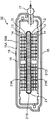
- FIG. It is a top view of the thermoelectric conversion module shown in FIG. 3 is a cross-sectional view taken along line II of the thermoelectric conversion module shown in FIG. 1
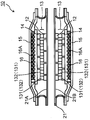
- FIG. 4 is a cross-sectional view taken along line II-II of the thermoelectric conversion module shown in FIG.
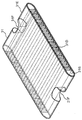
- FIG. 5 is a perspective view showing only the tubular body of the thermoelectric conversion module of the present embodiment.
- the thermoelectric conversion module 10 includes a cylindrical tube body 21 having a flat upper surface 21A and a lower surface 21B for flowing a compressive fluid, and an upper surface 21A side and a lower surface 21B of the tube body 21. It has high temperature side electrode parts 12 and 12 which are arranged on each side and are electrically insulated from tube 21.
- the p-type thermoelectric semiconductor 131 and the n-type thermoelectric semiconductor 132 are arranged in a matrix on the high temperature side electrode portions 12 and 12 so as to be adjacent to each other, and are electrically connected in series. Conversion elements 13 are provided.
- thermoelectric conversion elements 13 and 13 Furthermore, on the thermoelectric conversion elements 13 and 13, the low temperature side electrode portions 14 and 14 that electrically connect the p-type thermoelectric semiconductor 131 and the n-type thermoelectric semiconductor 132 in series are disposed, and are electrically insulated from the tube body 21. Has been abutted.
- fins 21D are disposed in the internal space corresponding to the upper and lower sides of the region of the tubular body 21 where the thermoelectric conversion elements 13, 13 are disposed, and both sides of the region of the tubular body 21 where the fins 21D are disposed.
- a sealing member 23 that seals the internal space 21S is disposed in the internal space 21S at the end of the tubular body 21 in front of the compressive fluid introduction direction indicated by an arrow in the drawing.
- the sealing member 23 can be incorporated into the internal space 21S simultaneously with the formation of the internal space 21S, or after the tubular body 21 is manufactured, the internal space can be obtained by performing post-processing. It can also be incorporated in 21S.
- the sealing member 23 is disposed in front of the compressive fluid introduction direction in the internal space 21S.
- An arrangement place is not limited, and may be arranged behind the compressive fluid in the internal space 21S in the introduction direction, or may be arranged at a substantially central portion of the internal space 21S.
- the sealing member 23 does not have to be a bulk material, and may be a plate-like so-called lid. This lid may also be disposed at the front and rear in the direction of introduction of the compressive fluid in the internal space 21S, or may be disposed at a substantially central portion of the internal space 21S.
- fins 21 ⁇ / b> D for efficiently transferring waste heat of the compressive fluid flowing in the pipe body 21 to the upper and lower surfaces 21 ⁇ / b> A and 21 ⁇ / b> B are formed inside the pipe body 21.
- the tube body 21, the high temperature side electrode parts 12 and 12, the thermoelectric conversion elements 13 and 13, and the low temperature side electrode parts 14 and 14 are housed in a case member 15 that is kept airtight. Between the case member 15, the upper wall surface 15 ⁇ / b> A and the lower wall surface 15 ⁇ / b> B of the case member 15 are formed through the refrigerant inlet 18 and the outlet 19 provided outside the case member 15 (thermoelectric conversion module 10). A space 16 is formed to cool and cool the low temperature side electrode portions 14 and 14 by introducing and discharging the refrigerant into the space (see FIG. 3).
- the case member 15 accommodates the high temperature side electrode portions 12, 12, the thermoelectric conversion elements 13, 13, and the low temperature side electrode portions 14, 14 in the cross section in the II-II direction.
- the portion where the gap 16 for flowing the coolant is formed is the thickest, and is configured to be thinned stepwise from the portion toward the outside.
- the space which accommodated the high temperature side electrode parts 12 and 12, the thermoelectric conversion elements 13 and 13 and the low temperature side electrode parts 14 and 14 of the case member 15 is evacuated and kept in a vacuum state.
- the high temperature side electrode portions 12 and 12 are in contact with the upper surface 21A and the lower surface 21B of the tube body 21, and the lower wall surface 15B that opposes the upper wall surface 15A that forms a space for flowing the refrigerant of the case member 15.
- the low temperature side electrode portions 14 and 14 are in contact with each other, either one may be joined with a brazing material or the like.
- the lower wall 15B of the case member 15 pressurizes the thermoelectric conversion elements 13 and 13 by evacuating the space containing the thermoelectric conversion elements 13 and 13 and the above-mentioned contact portion has a close adhesion. improves.
- a buffer material, a spare material, and the like are provided between the upper surface 21A and the lower surface 21B of the tube body 21 and the high temperature side electrode portions 12 and 12 as well as the lower wall surface 15B of the case member 15 and the low temperature side electrode. It can also be disposed so as to be sandwiched between the portions 14 and 14.
- thermoelectric conversion module 10 thermoelectric conversion module 10
- electrode terminals 17 and 17 for taking out the current generated in the thermoelectric conversion elements 13 and 13 to the outside are provided via the lead wires (not shown). 13 is electrically connected.
- the pipe body 21 and the sealing member 23 are made of, for example, stainless steel so that a compressive fluid such as exhaust gas from various industrial equipment and automobiles can flow and resists corrosive gas contained in the compressive fluid. Consists of.
- the high temperature side electrode portions 12 and 12 and the low temperature side electrode portions 14 and 14 are required to exhibit excellent heat resistance and mechanical strength and relatively high conductivity.
- the electrode terminals 17 and 17 can also be made of the same material.
- the p-type thermoelectric semiconductor 131 and the n-type thermoelectric semiconductor 132 constituting the thermoelectric conversion elements 13 and 13 are made of a material having low thermal conductivity, obtaining a large temperature difference between the high temperature side and the low temperature side, and generating a large potential difference by the Seebeck effect.
- it is made of a semiconductor material such as Bi—Te, Pb—Te, Si—Ge, or Mg—Si.
- the case member 15 is made of, for example, Mg, Al, Mo, Cu, W, Ti, Ni, Fe, and stainless steel from the viewpoints of weight reduction, corrosion resistance, and rigidity of various industrial equipment and automobiles on which the thermoelectric conversion module 10 is mounted. Or it can comprise from these alloys.
- the lead wire described below can be composed of a good electrical conductor such as Cu, Ag, Au, Ni, Fe, and alloys thereof.
- thermoelectric conversion module 10 In the thermoelectric conversion module 10 shown in FIGS. 1 to 4, a compressive fluid such as exhaust gas from various industrial equipment and automobiles is introduced into the tube body 21, and the upper surface 21 ⁇ / b> A of the tube body 21 and the waste heat of the compressive fluid are used. The lower surface 21B is heated.
- a refrigerant is introduced into the gap 16 of the case member 15. Heat that heats the upper surface 21A and the lower surface 21B of the tube body 21 is transmitted to the lower side of the thermoelectric conversion elements 13 and 13 via the high temperature side electrode portions 12 and 12, and heats the lower portions of the thermoelectric conversion elements 13 and 13.
- cold heat from the refrigerant introduced into the gap 16 is transmitted to the upper side of the thermoelectric conversion elements 13 and 13 via the low temperature side electrode portions 14 and 14, and cools the upper portions of the thermoelectric conversion elements 13 and 13.
- thermoelectric conversion elements 13 and 13 As a result, an electromotive force is generated in the thermoelectric conversion elements 13 and 13 by the Seebeck effect, and the p-type thermoelectric semiconductor 131 and the n-type thermoelectric semiconductor 132 constituting the thermoelectric conversion elements 13 and 13 are electrically connected in series by this electromotive force.
- the lead wire (not shown).
- the electrode terminals 17 and 17 are taken out of the thermoelectric conversion module 10.
- the Seebeck effect that is, the thermoelectric conversion efficiency increases as the temperature difference between the upper and lower sides of the thermoelectric conversion elements 13 and 13 increases, so that waste heat of the compressive fluid flowing in the tubular body 21 is possible. It is necessary to use it as effectively as possible.
- the sealing member 21S is disposed in both sides of the internal space where the fins 21D of the tubular body 21 are disposed, that is, in the internal space 21S located at the end of the tubular body 21.
- the compressive fluid is prevented from flowing in the internal space 21S. Therefore, the compressive fluid flows only in the internal space in which the fins 21D are formed, corresponding to the lower and upper areas of the tube body 21 where the thermoelectric conversion elements 13 and 13 are formed. That is, the pressure loss of the compressive fluid caused by flowing through the internal space 21S corresponding to the non-formation region of the thermoelectric conversion elements 13 and 13 can be suppressed.
- the waste heat from the compressive fluid is the tube in which the thermoelectric conversion elements 13 and 13 are disposed. Since the heat is efficiently transmitted only to the upper surface 21A and the lower surface 21B of the body 21, the utilization efficiency of the waste heat is improved. As a result, the waste heat of the compressive fluid flowing in the tubular body 21 can be efficiently transmitted to the lower part of the thermoelectric conversion elements 13 and 13, so that the Seebeck effect of the thermoelectric conversion elements 13 and 13 is improved and the thermoelectric conversion efficiency is increased. And more electrical energy can be extracted from the thermoelectric conversion module 10.
- thermoelectric conversion efficiency of the thermoelectric conversion elements 13 and 13 is improved by a simple method of constricting the flow path of the compressive fluid flowing in the tube body 21, and the thermoelectric conversion module 10 is greatly increased. Electric energy can be taken out.
- thermoelectric conversion module 6 to 8 are diagrams showing a schematic configuration of the thermoelectric conversion module in the present embodiment.
- the thermoelectric conversion module of the present embodiment shown in FIG. 6 is the same as that of the thermoelectric conversion module 10 of the first embodiment shown in FIG.
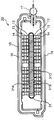
- the thermoelectric conversion module of this embodiment shown in FIG. 7 corresponds to the cross-sectional view shown in FIG. 3 of the thermoelectric conversion module 10 of the first embodiment.
- FIG. 8 is a perspective view showing only the tubular body of the thermoelectric conversion module of the present embodiment.
- thermoelectric conversion module of this embodiment since the schematic structure which shows the whole structure of the thermoelectric conversion module of this embodiment is the same as the structure shown in FIG. 1 of 1st Embodiment, description is abbreviate
- thermoelectric conversion module shown in FIGS.
- thermoelectric conversion module 30 of the present embodiment is different from the thermoelectric conversion module 10 of the first embodiment in that the sealing member 23 is disposed in the internal space 21S of the tube body 21 and closed, instead of the side surface of the tube body 31.
- the inner space 31S of the tubular body 31 is closed by processing a part of 31E and making it dent in the inner space 31S side and abut against the end of the fin 31D.
- the compressive fluid introduced into the pipe 31 forms fins 31D corresponding to the lower and upper areas of the pipe body 31 where the thermoelectric conversion elements 13 and 13 are formed.
- the internal space 31 ⁇ / b> S corresponding to the non-formation region of the thermoelectric conversion elements 13 and 13 does not flow.
- thermoelectric conversion elements 13 and 13 are arrange
- thermoelectric conversion efficiency of the thermoelectric conversion elements 13 and 13 is improved by a simple method of constricting the flow path of the compressive fluid flowing in the tubular body 31, and the thermoelectric conversion module 30 is greatly increased. Electric energy can be taken out.
- thermoelectric conversion module 10 in 1st Embodiment since it is the same as that of the thermoelectric conversion module 10 in 1st Embodiment about another structure and characteristic, description is abbreviate
- FIG. 9 to 13 are diagrams showing a schematic configuration of the thermoelectric conversion module in the present embodiment
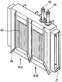
- FIG. 9 is a perspective view schematically showing an example of the thermoelectric conversion module of the present embodiment
- FIG. FIG. 10 is a perspective view of a state where a second case member outside the thermoelectric conversion module shown in FIG. 9 is removed.
- FIG. 11 is a perspective view in a state in which the second case member outside the thermoelectric conversion module shown in FIG. 9 and the first case member that houses the thermoelectric conversion element and the like inside the second case member are removed.
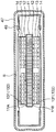
- FIG. 12 is a cross-sectional view taken along line III-III of the thermoelectric conversion module shown in FIG. 9, and
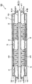
- FIG. 13 is a cross-sectional view taken along line IV-IV of the thermoelectric conversion module shown in FIG.
- the thermoelectric conversion module 40 includes a cylindrical tube body 41 having a flat upper surface 41A and a lower surface 41B for flowing a compressive fluid, and an upper surface 41A side and a lower surface 41B side of the tube body 41.
- Each has a high temperature side electrode portion 12, 12 disposed and electrically insulated from the tube body 41.
- the p-type thermoelectric semiconductor 131 and the n-type thermoelectric semiconductor 132 are arranged in a matrix on the high temperature side electrode portions 12 and 12 so as to be adjacent to each other, and are electrically connected in series. Conversion elements 13 are provided.
- low temperature side electrode portions 14, 14 that electrically connect the p-type thermoelectric semiconductor 131 and the n-type thermoelectric semiconductor 132 in series are disposed.
- the tube body 41, the high temperature side electrode portions 12 and 12, the thermoelectric conversion elements 13 and 13, and the low temperature side electrode portions 14 and 14 are disposed in the first case member 46.
- the first case member 46 has a second refrigerant chamber S formed between the first case member 46 and the first case member 46. Housed in the case member 47.
- the second case member 47 is formed with an inlet 47A for introducing the refrigerant into the refrigerant chamber S.
- a flow path guide plate 48 is disposed so as to narrow toward the center.
- the flow path guide plate 48 is joined to the lower wall surface 47B of the second case member 47, and a gap g is formed between the upper wall surface 46A of the first case member 46. .
- fins 49 that are heat exchange members are disposed in the refrigerant chamber S, specifically, in the region inside the flow path guide plate 48.
- thermoelectric conversion element 13 including the tube body 41 for flowing the compressive fluid in the thermoelectric conversion module 40 of the present embodiment, the high temperature side electrode portions 12 and 12, the p-type thermoelectric semiconductor 131 and the n-type thermoelectric semiconductor 132, and It is formed between the first case member 46 that houses the low-temperature side electrode portions 14 and 14 and the second case member 47 that is outside the first case member and houses the first case member.
- a flow path guide plate 48 formed so as to be narrowed from the inlet of the refrigerant chamber S toward the formation region of the thermoelectric conversion elements 13 and 13 is disposed. Therefore, the refrigerant flowing in the refrigerant chamber S is forcibly supplied to the formation region of the thermoelectric conversion elements 13 and 13, and the region can be cooled more efficiently and effectively.
- thermoelectric conversion elements 13 and 13 the cold heat from the refrigerant is efficiently transmitted to the low-temperature heat source side of the thermoelectric conversion elements 13 and 13.
- the utilization efficiency of the refrigerant is improved.
- the Seebeck effect of the thermoelectric conversion elements 13 and 13 is improved, the thermoelectric conversion efficiency is improved, and larger electric energy can be extracted from the thermoelectric conversion module 40.
- thermoelectric conversion module 40 of the present embodiment the thermoelectric conversion element 13 from the inlet of the refrigerant chamber S into the refrigerant chamber S formed between the first case member 46 and the second case member 47,
- the thermoelectric conversion efficiency of the thermoelectric conversion elements 13 and 13 is improved by a simple method of disposing the flow path guide plate 48 formed so as to be narrowed toward the formation region of the thermoelectric conversion module 40. Big electric energy can be taken out.
- the gap g may be formed over the entire flow path guide plate 48 or a part of the flow path guide plate 48 as long as the above-described effects are exhibited.
- the flow path guide plate 48 is fixed to the lower wall surface of the second case member 47, the flow path guide plate 48 is not displaced by the refrigerant flowing through the inside, and the above-mentioned description is made.
- the refrigerant can be stably supplied to the formation region of the thermoelectric conversion elements 13 and 13, and the gap g can be reliably formed between the first case member 46.
- the fins 49 that are heat exchange members are disposed in the refrigerant chamber S, the cold heat of the refrigerant flowing in the refrigerant chamber S via the fins 49 is more effective. Since the heat is efficiently transmitted to the low-temperature heat source 13 and 13, the utilization efficiency of the refrigerant is further improved. As a result, since the Seebeck effect of the thermoelectric conversion elements 13 and 13 is further improved, the thermoelectric conversion efficiency is further improved, and a larger electric energy can be extracted from the thermoelectric conversion module 40.
- thermoelectric conversion module 40 of the present embodiment the high temperature side electrode portions 12, 12, the thermoelectric conversion elements 13, 13, and the low temperature side electrode portions 14, 14 are connected to the upper surface 41 ⁇ / b> A of the tubular body 41.
- the lower surface 41B is formed over a plurality of regions, the thermoelectric conversion elements 13, 13 and the like formed in each region include, for example, electrode portions 14A formed at the end portions of the low temperature side electrode portions 14, 14.
- the current (voltage) generated by the thermoelectric conversion elements 13 and 13 in each region is electrically connected via a wiring (not shown), and an electrode terminal 45 connected to the electrode portion 14C located at the lowermost left end. Is taken out (see FIG. 9).
- thermoelectric conversion module is improved in thermoelectric conversion efficiency and uses heat from waste heat of compressible fluid such as exhaust gas in various industrial equipment and automobiles, etc. 10 can be provided.
- FIG. 14 is a cross-sectional view showing a schematic configuration of the thermoelectric conversion module 50 in the present embodiment, and corresponds to FIG. 13 of the thermoelectric conversion module 40 of the third embodiment.
- the same reference numerals are used for the same or similar components as those of the thermoelectric conversion module 40 shown in FIGS.
- the flow path guide plate 48 is fixed to the upper wall surface 46A of the first case member 46, the flow path guide plate 48 is not displaced by the refrigerant flowing inside the first case member 46, and is described above. As described above, the refrigerant can be stably supplied to the formation region of the thermoelectric conversion elements 13, 13, and the gap g can be reliably formed between the second case member 47.
- thermoelectric conversion module 40 in the third embodiment is the same as those of the thermoelectric conversion module 40 in the third embodiment, and thus description thereof is omitted.
- FIG. 15 and 16 are diagrams showing a schematic configuration of the thermoelectric conversion module 60 in the present embodiment
- FIG. 15 is a perspective view schematically showing an example of the thermoelectric conversion module of the present embodiment
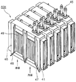
- FIG. FIG. 16 is a perspective view of a state where a second case member outside the thermoelectric conversion module shown in FIG. 15 is removed.
- thermoelectric conversion module 40 shown in FIGS. 9-13.
- thermoelectric conversion module 60 of the present embodiment is in a state as shown in FIG. 10 from which the first case member 46 of the thermoelectric conversion module 40 of the third embodiment is removed.
- Five thermoelectric conversion module assemblies 60 ⁇ / b> X are stacked via a flow path guide plate 48, and a second case member 67 is disposed so as to store the stacked body.
- the flow path guide plate 48 is a refrigerant formed between the first case member 46 and the second case member 67. It is arranged indoors.
- the second case member 67 is provided with flange portions 672 on both sides of the main portion 671 in which the refrigerant introduction port 67A is formed.
- Each assembly 60X of the thermoelectric conversion module 60 of the present embodiment is provided on the flange portion 672.
- An opening 67A for introducing a compressive fluid is formed in the tube body 41.
- thermoelectric conversion including the tube body 41 for flowing the compressive fluid, the high temperature side electrode portions 12 and 12, the p-type thermoelectric semiconductor 131, and the n-type thermoelectric semiconductor 132.
- a first case member 46 that houses the element 13 and the low temperature side electrode portions 14, 14; a second case member 67 that is outside the first case member 46 and houses the first case member 46;
- a flow path guide plate 48 formed so as to be narrowed from the inlet 67A of the refrigerant chamber toward the formation region of the thermoelectric conversion elements 13 and 13 is disposed in the refrigerant chamber formed between the two. Therefore, the refrigerant flowing in the refrigerant chamber is forcibly supplied to the formation region of the thermoelectric conversion elements 13 and 13, and the region can be cooled more efficiently and effectively.
- thermoelectric conversion elements 13 and 13 the cold heat from the refrigerant is efficiently transmitted to the low-temperature heat source side of the thermoelectric conversion elements 13 and 13.
- the utilization efficiency of the refrigerant is improved.
- the Seebeck effect of the thermoelectric conversion elements 13 and 13 is improved, the thermoelectric conversion efficiency is improved, and larger electric energy can be extracted from the thermoelectric conversion module 60.
- thermoelectric conversion elements 13 and 13 are introduced into the refrigerant chamber formed between the first case member 46 and the second case member 67 from the inlet 67A of the refrigerant chamber.
- the thermoelectric conversion efficiency of the thermoelectric conversion elements 13 and 13 is improved by a simple method of disposing the flow path guide plate 48 formed so as to be constricted toward the formation region. Energy can be extracted.
- thermoelectric conversion elements 13 and 13 in each assembly 60X of the thermoelectric conversion module are connected substantially in parallel by taking the structure of a laminated body as shown in FIG. Therefore, much larger electric energy than the thermoelectric conversion module 40 shown in the first embodiment can be extracted from the thermoelectric conversion module 60 of the present embodiment.
- thermoelectric conversion module 40 in the third embodiment is the same as those of the thermoelectric conversion module 40 in the third embodiment, and thus description thereof is omitted.
- thermoelectric conversion module 10, 20, 40, 50, 60 thermoelectric conversion module; 21, 31, 41 tube; 21D, 31D (in the tube) fins; 12 high temperature side electrode part; 13 thermoelectric conversion element; 14 low temperature side electrode part; 15 case Member; 16; gap (between low temperature side electrode part and case member); 17 electrode terminal; 18 refrigerant inlet; 19 refrigerant outlet; 21S, 31S internal space corresponding to non-formation region of thermoelectric conversion element of tubular body; Sealing member; 31F dent processing; 45 electrode terminal; 46 first case member; 47 second case member; 48 channel guide plate; 49 fin.
Landscapes
- Cooling Or The Like Of Semiconductors Or Solid State Devices (AREA)
Abstract
Description
図1~図5は、本実施形態における熱電変換モジュールの概略構成を示す図であり、図1は、本実施形態の熱電変換モジュールの一例を概略的に示す斜視図であり、図2は、図1に示す熱電変換モジュールの平面図である。また、図3は、図1に示す熱電変換モジュールのI-I線に沿った断面図であり、図4は、図1に示す熱電変換モジュールのII-II線に沿った断面図である。さらに、図5は、本実施形態の熱電変換モジュールの管体のみを取り出して示す斜視図である。
図6~図8は、本実施形態における熱電変換モジュールの概略構成を示す図であり、図6に示す本実施形態の熱電変換モジュールは、第1の実施形態の熱電変換モジュール10の、図2に示す平面図に相当するものであり、図7に示す本実施形態の熱電変換モジュールは、第1の実施形態の熱電変換モジュール10の、図3に示す断面図に相当するものである。また、図8は、本実施形態の熱電変換モジュールの管体のみを取り出して示す斜視図である。
図9~図13は、本実施形態における熱電変換モジュールの概略構成を示す図であり、図9は、本実施形態の熱電変換モジュールの一例を概略的に示す斜視図であり、図10は、図9に示す熱電変換モジュールの外側の第2のケース部材を取り外した状態の斜視図である。また、図11は、図9に示す熱電変換モジュールの外側の第2のケース部材及び第2のケース部材の内側であって熱電変換素子等を収納する第1のケース部材を取り外した状態の斜視図である。さらに、図12は、図9に示す熱電変換モジュールのIII-III線に沿った断面図であり、図13は、図9に示す熱電変換モジュールのIV-IV線に沿った断面図である。
図14は、本実施形態における熱電変換モジュール50の概略構成を示す断面図であり、第3の実施形態の熱電変換モジュール40の図13に相当するものである。なお、図9~図13に示す熱電変換モジュール40の構成要素と同一あるいは類似の構成要素については、同一の符号を用いている。
図15及び図16は、本実施形態における熱電変換モジュール60の概略構成を示す図であり、図15は、本実施形態の熱電変換モジュールの一例を概略的に示す斜視図であり、図16は、図15に示す熱電変換モジュールの外側の第2のケース部材を取り外した状態の斜視図である。
Claims (8)
- 圧縮性流体を流すための筒状の管体と、
前記管体の上面側及び下面側それぞれに配設され、前記管体と電気的に絶縁された高温側電極部と、
前記高温側電極部上において、少なくとも一対のp型熱電半導体及びn型熱電半導体が電気的に直列に接続された熱電変換素子と、
前記熱電変換素子上において、前記p型熱電半導体及び前記n型熱電半導体を電気的に直列に接続する低温側電極部と、
前記低温側電極部との間に冷媒を流すための空隙を設けるようにして、前記管体、前記高温側電極部、前記熱電変換素子、及び前記低温側電極部を収納するための第1のケース部材とを具え、
前記圧縮性流体又は前記冷媒を、前記管体の内方又は外方において、前記熱電変換素子の形成領域に流すように構成したことを特徴とする、熱電変換モジュール。 - 前記管体の、前記圧縮性流体の流路方向と略垂直な方向であって、前記熱電変換素子の非形成領域に相当する内部空間の少なくとも一部を閉塞させたことを特徴とする、請求項1に記載の熱電変換モジュール。
- 前記内部空間の閉塞は、前記管体の当該内部空間に封止部材を配設して行うことを特徴とする、請求項2に記載の熱電変換モジュール。
- 前記内部空間の閉塞は、前記管体の少なくとも側面を前記内部空間側に凹ませて行うことを特徴とする、請求項2に記載の熱電変換モジュール。
- 前記第1のケース部材の外方であって、前記低温側電極部との間に冷媒を流すための冷媒室が形成されるようにして配設され、前記第1のケース部材を収納するための第2のケース部材と
前記冷媒室内において、前記冷媒室の導入口から前記熱電変換素子の形成領域に向けて狭窄されるようにして配設された流路ガイド板と、
を具えることを特徴とする、請求項1に記載の熱電変換モジュール。 - 前記流路ガイド板は、前記第1のケース部材における上壁面の少なくとも一部又は前記第2のケース部材における下壁面の少なくとも一部間に、隙間を形成するようにして配設されたことを特徴とする、請求項5に記載の熱電変換モジュール。
- 前記流路ガイド板は、前記第1のケース部材における上壁面の少なくとも一部又は前記第2のケース部材における下壁面の少なくとも一部に、接合されていることを特徴とする、請求項6に記載の熱電変換モジュール。
- 前記冷媒室内には、熱交換部材が配設されていることを特徴とする、請求項5~7のいずれか一に記載の熱電変換モジュール。
Priority Applications (3)
| Application Number | Priority Date | Filing Date | Title |
|---|---|---|---|
| US14/435,553 US20150303365A1 (en) | 2012-10-26 | 2013-10-25 | Thermoelectric conversion module |
| CN201380055685.3A CN104919610A (zh) | 2012-10-26 | 2013-10-25 | 热电变换模块 |
| DE112013005148.6T DE112013005148T5 (de) | 2012-10-26 | 2013-10-25 | Thermoelektrisches Umwandlungsmodul |
Applications Claiming Priority (4)
| Application Number | Priority Date | Filing Date | Title |
|---|---|---|---|
| JP2012-236208 | 2012-10-26 | ||
| JP2012236208A JP5988827B2 (ja) | 2012-10-26 | 2012-10-26 | 熱電変換モジュール |
| JP2013-087813 | 2013-04-18 | ||
| JP2013087813A JP6002623B2 (ja) | 2013-04-18 | 2013-04-18 | 熱電変換モジュール |
Publications (1)
| Publication Number | Publication Date |
|---|---|
| WO2014064945A1 true WO2014064945A1 (ja) | 2014-05-01 |
Family
ID=50544329
Family Applications (1)
| Application Number | Title | Priority Date | Filing Date |
|---|---|---|---|
| PCT/JP2013/006335 Ceased WO2014064945A1 (ja) | 2012-10-26 | 2013-10-25 | 熱電変換モジュール |
Country Status (4)
| Country | Link |
|---|---|
| US (1) | US20150303365A1 (ja) |
| CN (1) | CN104919610A (ja) |
| DE (1) | DE112013005148T5 (ja) |
| WO (1) | WO2014064945A1 (ja) |
Cited By (3)
| Publication number | Priority date | Publication date | Assignee | Title |
|---|---|---|---|---|
| WO2015049628A1 (en) | 2013-10-04 | 2015-04-09 | Tata Consultancy Services Limited | Optimizing data center cooling efficiency |
| DE102014219853A1 (de) * | 2014-05-06 | 2015-11-26 | Mahle International Gmbh | Thermoelektrischer Generator |
| CN108028616A (zh) * | 2015-09-16 | 2018-05-11 | 株式会社电装 | 热电发电装置 |
Families Citing this family (4)
| Publication number | Priority date | Publication date | Assignee | Title |
|---|---|---|---|---|
| USD816198S1 (en) * | 2015-01-28 | 2018-04-24 | Phononic, Inc. | Thermoelectric heat pump |
| JP6639426B2 (ja) * | 2017-01-05 | 2020-02-05 | 株式会社ユタカ技研 | 熱電発電装置 |
| JP7072004B2 (ja) * | 2017-06-08 | 2022-05-19 | エルジー イノテック カンパニー リミテッド | 熱変換装置 |
| USD833588S1 (en) | 2017-10-11 | 2018-11-13 | Phononic, Inc. | Thermoelectric heat pump |
Citations (7)
| Publication number | Priority date | Publication date | Assignee | Title |
|---|---|---|---|---|
| US5974803A (en) * | 1997-04-17 | 1999-11-02 | Webasto Thermosysteme Gmbh | Thermogenerator for power production in conjunction with a heating device |
| JP2000018095A (ja) * | 1998-06-30 | 2000-01-18 | Nissan Motor Co Ltd | 排熱発電装置 |
| JP2005057908A (ja) * | 2003-08-05 | 2005-03-03 | Toyota Motor Corp | 排熱エネルギ回収装置 |
| JP2007157908A (ja) * | 2005-12-02 | 2007-06-21 | Toyota Motor Corp | 熱発電装置 |
| US20120012146A1 (en) * | 2009-04-02 | 2012-01-19 | Avl List Gmbh | Thermoelectric generator unit |
| JP2012057579A (ja) * | 2010-09-10 | 2012-03-22 | Mitsubishi Fuso Truck & Bus Corp | 内燃機関のegrクーラ |
| JP2012508342A (ja) * | 2008-10-27 | 2012-04-05 | コーニング インコーポレイテッド | エネルギー変換装置及び方法 |
-
2013
- 2013-10-25 WO PCT/JP2013/006335 patent/WO2014064945A1/ja not_active Ceased
- 2013-10-25 US US14/435,553 patent/US20150303365A1/en not_active Abandoned
- 2013-10-25 CN CN201380055685.3A patent/CN104919610A/zh active Pending
- 2013-10-25 DE DE112013005148.6T patent/DE112013005148T5/de not_active Withdrawn
Patent Citations (7)
| Publication number | Priority date | Publication date | Assignee | Title |
|---|---|---|---|---|
| US5974803A (en) * | 1997-04-17 | 1999-11-02 | Webasto Thermosysteme Gmbh | Thermogenerator for power production in conjunction with a heating device |
| JP2000018095A (ja) * | 1998-06-30 | 2000-01-18 | Nissan Motor Co Ltd | 排熱発電装置 |
| JP2005057908A (ja) * | 2003-08-05 | 2005-03-03 | Toyota Motor Corp | 排熱エネルギ回収装置 |
| JP2007157908A (ja) * | 2005-12-02 | 2007-06-21 | Toyota Motor Corp | 熱発電装置 |
| JP2012508342A (ja) * | 2008-10-27 | 2012-04-05 | コーニング インコーポレイテッド | エネルギー変換装置及び方法 |
| US20120012146A1 (en) * | 2009-04-02 | 2012-01-19 | Avl List Gmbh | Thermoelectric generator unit |
| JP2012057579A (ja) * | 2010-09-10 | 2012-03-22 | Mitsubishi Fuso Truck & Bus Corp | 内燃機関のegrクーラ |
Cited By (4)
| Publication number | Priority date | Publication date | Assignee | Title |
|---|---|---|---|---|
| WO2015049628A1 (en) | 2013-10-04 | 2015-04-09 | Tata Consultancy Services Limited | Optimizing data center cooling efficiency |
| DE102014219853A1 (de) * | 2014-05-06 | 2015-11-26 | Mahle International Gmbh | Thermoelektrischer Generator |
| CN108028616A (zh) * | 2015-09-16 | 2018-05-11 | 株式会社电装 | 热电发电装置 |
| US11024787B2 (en) | 2015-09-16 | 2021-06-01 | Denso Corporation | Thermoelectric power generation device |
Also Published As
| Publication number | Publication date |
|---|---|
| CN104919610A (zh) | 2015-09-16 |
| US20150303365A1 (en) | 2015-10-22 |
| DE112013005148T5 (de) | 2015-07-23 |
Similar Documents
| Publication | Publication Date | Title |
|---|---|---|
| WO2014064945A1 (ja) | 熱電変換モジュール | |
| US10026886B2 (en) | System for thermoelectric energy generation | |
| US20110265838A1 (en) | Packaged thermoelectric conversion module | |
| US20130213449A1 (en) | Thermoelectric plate and frame exchanger | |
| JPH1052077A (ja) | 熱電モジュール | |
| JP6078412B2 (ja) | 熱電変換式発電装置 | |
| JP6117342B2 (ja) | 熱電発電器を有する熱交換器 | |
| KR101473899B1 (ko) | 열전모듈 열교환기 | |
| US20180287517A1 (en) | Phase change inhibited heat-transfer thermoelectric power generation device and manufacturing method thereof | |
| JP6002623B2 (ja) | 熱電変換モジュール | |
| CN109891611B (zh) | 传热设备 | |
| JP5988827B2 (ja) | 熱電変換モジュール | |
| WO2019181683A1 (ja) | 熱電変換モジュール | |
| KR20210090997A (ko) | 발전장치 | |
| EP4362117A1 (en) | Thermoelectric device | |
| CN105579680A (zh) | 利用与热源直接接触的热电模块进行热电发电的热交换器 | |
| JP7684993B2 (ja) | 熱電モジュールおよびこれを含む発電装置 | |
| KR102941993B1 (ko) | 열전모듈 및 이를 포함하는 발전장치 | |
| US12336430B2 (en) | Thermoelectric module and power generation apparatus including the same | |
| JP7278030B2 (ja) | 熱電発電装置 | |
| RU2736734C1 (ru) | Термоэлектрическая батарея. | |
| JP7589468B2 (ja) | 熱電変換装置 | |
| JP2014086649A (ja) | 熱電変換モジュール | |
| KR102825498B1 (ko) | 발전장치 | |
| JP2018010908A (ja) | 熱電変換装置、熱電変換モジュール、および熱電変換方法 |
Legal Events
| Date | Code | Title | Description |
|---|---|---|---|
| 121 | Ep: the epo has been informed by wipo that ep was designated in this application |
Ref document number: 13848991 Country of ref document: EP Kind code of ref document: A1 |
|
| WWE | Wipo information: entry into national phase |
Ref document number: 14435553 Country of ref document: US |
|
| NENP | Non-entry into the national phase |
Ref country code: DE |
|
| WWE | Wipo information: entry into national phase |
Ref document number: 1120130051486 Country of ref document: DE Ref document number: 112013005148 Country of ref document: DE |
|
| 122 | Ep: pct application non-entry in european phase |
Ref document number: 13848991 Country of ref document: EP Kind code of ref document: A1 |