WO2014064882A1 - 密閉型二次電池 - Google Patents
密閉型二次電池 Download PDFInfo
- Publication number
- WO2014064882A1 WO2014064882A1 PCT/JP2013/005507 JP2013005507W WO2014064882A1 WO 2014064882 A1 WO2014064882 A1 WO 2014064882A1 JP 2013005507 W JP2013005507 W JP 2013005507W WO 2014064882 A1 WO2014064882 A1 WO 2014064882A1
- Authority
- WO
- WIPO (PCT)
- Prior art keywords
- secondary battery
- sealed secondary
- opening
- battery
- cap
- Prior art date
- Legal status (The legal status is an assumption and is not a legal conclusion. Google has not performed a legal analysis and makes no representation as to the accuracy of the status listed.)
- Ceased
Links
Images
Classifications
-
- H—ELECTRICITY
- H01—ELECTRIC ELEMENTS
- H01M—PROCESSES OR MEANS, e.g. BATTERIES, FOR THE DIRECT CONVERSION OF CHEMICAL ENERGY INTO ELECTRICAL ENERGY
- H01M10/00—Secondary cells; Manufacture thereof
- H01M10/04—Construction or manufacture in general
- H01M10/0431—Cells with wound or folded electrodes
-
- H—ELECTRICITY
- H01—ELECTRIC ELEMENTS
- H01M—PROCESSES OR MEANS, e.g. BATTERIES, FOR THE DIRECT CONVERSION OF CHEMICAL ENERGY INTO ELECTRICAL ENERGY
- H01M10/00—Secondary cells; Manufacture thereof
- H01M10/05—Accumulators with non-aqueous electrolyte
- H01M10/052—Li-accumulators
- H01M10/0525—Rocking-chair batteries, i.e. batteries with lithium insertion or intercalation in both electrodes; Lithium-ion batteries
-
- H—ELECTRICITY
- H01—ELECTRIC ELEMENTS
- H01M—PROCESSES OR MEANS, e.g. BATTERIES, FOR THE DIRECT CONVERSION OF CHEMICAL ENERGY INTO ELECTRICAL ENERGY
- H01M10/00—Secondary cells; Manufacture thereof
- H01M10/05—Accumulators with non-aqueous electrolyte
- H01M10/058—Construction or manufacture
- H01M10/0585—Construction or manufacture of accumulators having only flat construction elements, i.e. flat positive electrodes, flat negative electrodes and flat separators
-
- H—ELECTRICITY
- H01—ELECTRIC ELEMENTS
- H01M—PROCESSES OR MEANS, e.g. BATTERIES, FOR THE DIRECT CONVERSION OF CHEMICAL ENERGY INTO ELECTRICAL ENERGY
- H01M50/00—Constructional details or processes of manufacture of the non-active parts of electrochemical cells other than fuel cells, e.g. hybrid cells
- H01M50/10—Primary casings; Jackets or wrappings
- H01M50/147—Lids or covers
- H01M50/148—Lids or covers characterised by their shape
- H01M50/152—Lids or covers characterised by their shape for cells having curved cross-section, e.g. round or elliptic
-
- H—ELECTRICITY
- H01—ELECTRIC ELEMENTS
- H01M—PROCESSES OR MEANS, e.g. BATTERIES, FOR THE DIRECT CONVERSION OF CHEMICAL ENERGY INTO ELECTRICAL ENERGY
- H01M50/00—Constructional details or processes of manufacture of the non-active parts of electrochemical cells other than fuel cells, e.g. hybrid cells
- H01M50/10—Primary casings; Jackets or wrappings
- H01M50/147—Lids or covers
- H01M50/155—Lids or covers characterised by the material
- H01M50/157—Inorganic material
- H01M50/159—Metals
-
- H—ELECTRICITY
- H01—ELECTRIC ELEMENTS
- H01M—PROCESSES OR MEANS, e.g. BATTERIES, FOR THE DIRECT CONVERSION OF CHEMICAL ENERGY INTO ELECTRICAL ENERGY
- H01M50/00—Constructional details or processes of manufacture of the non-active parts of electrochemical cells other than fuel cells, e.g. hybrid cells
- H01M50/30—Arrangements for facilitating escape of gases
- H01M50/342—Non-re-sealable arrangements
- H01M50/3425—Non-re-sealable arrangements in the form of rupturable membranes or weakened parts, e.g. pierced with the aid of a sharp member
-
- H—ELECTRICITY
- H01—ELECTRIC ELEMENTS
- H01M—PROCESSES OR MEANS, e.g. BATTERIES, FOR THE DIRECT CONVERSION OF CHEMICAL ENERGY INTO ELECTRICAL ENERGY
- H01M50/00—Constructional details or processes of manufacture of the non-active parts of electrochemical cells other than fuel cells, e.g. hybrid cells
- H01M50/40—Separators; Membranes; Diaphragms; Spacing elements inside cells
- H01M50/409—Separators, membranes or diaphragms characterised by the material
- H01M50/411—Organic material
- H01M50/414—Synthetic resins, e.g. thermoplastics or thermosetting resins
- H01M50/417—Polyolefins
-
- H—ELECTRICITY
- H01—ELECTRIC ELEMENTS
- H01M—PROCESSES OR MEANS, e.g. BATTERIES, FOR THE DIRECT CONVERSION OF CHEMICAL ENERGY INTO ELECTRICAL ENERGY
- H01M50/00—Constructional details or processes of manufacture of the non-active parts of electrochemical cells other than fuel cells, e.g. hybrid cells
- H01M50/50—Current conducting connections for cells or batteries
- H01M50/531—Electrode connections inside a battery casing
-
- H—ELECTRICITY
- H01—ELECTRIC ELEMENTS
- H01M—PROCESSES OR MEANS, e.g. BATTERIES, FOR THE DIRECT CONVERSION OF CHEMICAL ENERGY INTO ELECTRICAL ENERGY
- H01M50/00—Constructional details or processes of manufacture of the non-active parts of electrochemical cells other than fuel cells, e.g. hybrid cells
- H01M50/50—Current conducting connections for cells or batteries
- H01M50/543—Terminals
- H01M50/562—Terminals characterised by the material
-
- H—ELECTRICITY
- H01—ELECTRIC ELEMENTS
- H01M—PROCESSES OR MEANS, e.g. BATTERIES, FOR THE DIRECT CONVERSION OF CHEMICAL ENERGY INTO ELECTRICAL ENERGY
- H01M50/00—Constructional details or processes of manufacture of the non-active parts of electrochemical cells other than fuel cells, e.g. hybrid cells
- H01M50/50—Current conducting connections for cells or batteries
- H01M50/572—Means for preventing undesired use or discharge
- H01M50/574—Devices or arrangements for the interruption of current
- H01M50/581—Devices or arrangements for the interruption of current in response to temperature
-
- H—ELECTRICITY
- H01—ELECTRIC ELEMENTS
- H01M—PROCESSES OR MEANS, e.g. BATTERIES, FOR THE DIRECT CONVERSION OF CHEMICAL ENERGY INTO ELECTRICAL ENERGY
- H01M50/00—Constructional details or processes of manufacture of the non-active parts of electrochemical cells other than fuel cells, e.g. hybrid cells
- H01M50/50—Current conducting connections for cells or batteries
- H01M50/572—Means for preventing undesired use or discharge
- H01M50/584—Means for preventing undesired use or discharge for preventing incorrect connections inside or outside the batteries
- H01M50/59—Means for preventing undesired use or discharge for preventing incorrect connections inside or outside the batteries characterised by the protection means
- H01M50/593—Spacers; Insulating plates
-
- H—ELECTRICITY
- H01—ELECTRIC ELEMENTS
- H01M—PROCESSES OR MEANS, e.g. BATTERIES, FOR THE DIRECT CONVERSION OF CHEMICAL ENERGY INTO ELECTRICAL ENERGY
- H01M10/00—Secondary cells; Manufacture thereof
- H01M10/05—Accumulators with non-aqueous electrolyte
- H01M10/058—Construction or manufacture
- H01M10/0587—Construction or manufacture of accumulators having only wound construction elements, i.e. wound positive electrodes, wound negative electrodes and wound separators
-
- Y—GENERAL TAGGING OF NEW TECHNOLOGICAL DEVELOPMENTS; GENERAL TAGGING OF CROSS-SECTIONAL TECHNOLOGIES SPANNING OVER SEVERAL SECTIONS OF THE IPC; TECHNICAL SUBJECTS COVERED BY FORMER USPC CROSS-REFERENCE ART COLLECTIONS [XRACs] AND DIGESTS
- Y02—TECHNOLOGIES OR APPLICATIONS FOR MITIGATION OR ADAPTATION AGAINST CLIMATE CHANGE
- Y02E—REDUCTION OF GREENHOUSE GAS [GHG] EMISSIONS, RELATED TO ENERGY GENERATION, TRANSMISSION OR DISTRIBUTION
- Y02E60/00—Enabling technologies; Technologies with a potential or indirect contribution to GHG emissions mitigation
- Y02E60/10—Energy storage using batteries
-
- Y—GENERAL TAGGING OF NEW TECHNOLOGICAL DEVELOPMENTS; GENERAL TAGGING OF CROSS-SECTIONAL TECHNOLOGIES SPANNING OVER SEVERAL SECTIONS OF THE IPC; TECHNICAL SUBJECTS COVERED BY FORMER USPC CROSS-REFERENCE ART COLLECTIONS [XRACs] AND DIGESTS
- Y02—TECHNOLOGIES OR APPLICATIONS FOR MITIGATION OR ADAPTATION AGAINST CLIMATE CHANGE
- Y02P—CLIMATE CHANGE MITIGATION TECHNOLOGIES IN THE PRODUCTION OR PROCESSING OF GOODS
- Y02P70/00—Climate change mitigation technologies in the production process for final industrial or consumer products
- Y02P70/50—Manufacturing or production processes characterised by the final manufactured product
Definitions
- the present invention relates to an improvement in a sealed secondary battery provided with a safety valve that exhausts gas generated in the battery to the outside of the battery.
- a conventional sealed secondary battery (hereinafter sometimes simply referred to as “battery”) has the following configuration.
- the opening of the battery case is sealed by a sealing body having a safety valve via a gasket.
- An upper insulating plate is disposed at the upper end of the electrode group.
- a lower insulating plate is disposed at the lower end of the electrode group.
- the safety valve When gas is generated in the battery due to overheating and the pressure in the battery rises and exceeds a predetermined pressure, the safety valve is activated and the gas generated in the battery is exhausted outside the battery.
- the electrode group when the pressure in the battery rises, the electrode group may be deformed and the safety valve may be blocked. In such a case, there is a possibility that the battery case may burst without the safety valve functioning effectively.
- Patent Document 1 describes a technique in which a phenolic resin laminate including a glass cloth as a base material and containing an inorganic additive is used as an upper insulating plate. Thereby, the deformation of the electrode group is prevented and the safety valve is prevented from being blocked.
- an object of the present invention is to safely exhaust gas generated in a battery to the outside of the battery even if gas is generated in the battery in the sealed secondary battery.
- a sealed secondary battery according to the present invention is a sealed secondary battery in which an electrode group in which a positive electrode plate and a negative electrode plate are wound or stacked with a separator interposed therebetween is accommodated in a battery case. And an insulating plate disposed on an end surface of the battery case in the electrode case on the opening side, and a sealing body that seals the opening of the battery case and has a cap. 1 opening portion and second opening portion are formed.
- S1 and S2 are 1.2 ⁇ S1 + 50 mm 2.
- ⁇ S2 ⁇ 5.0 ⁇ S1 + 50 mm 2 is satisfied.
- the gas generated in the battery can be safely exhausted outside the battery.
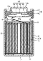
- FIG. 1 is a cross-sectional view showing a configuration of a sealed secondary battery according to an embodiment of the present invention.
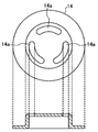
- FIG. 2 is a diagram showing the configuration of the cap, in which the upper side of FIG. 2 shows a planar configuration and the lower side of FIG. 2 shows a sectional configuration.
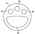
- FIG. 3 is a plan view showing the configuration of the insulating plate.
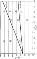
- FIG. 4 is a diagram showing the relationship between the area of the opening of the cap and the area of the opening of the insulating plate, and the results of the safety test.
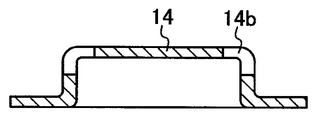
- FIG. 5 is a cross-sectional view showing the configuration of the cap.
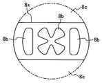
- FIG. 6 is a plan view showing the configuration of the insulating plate.
- FIG. 1 is a cross-sectional view illustrating a configuration of a sealed secondary battery according to the present embodiment.
- FIG. 2 is a diagram showing the configuration of the cap, in which the upper side of FIG. 2 shows a planar configuration and the lower side of FIG. 2 shows a cross-sectional configuration.
- FIG. 3 is a plan view showing the configuration of the insulating plate.
- a case where a lithium ion secondary battery is used as the sealed secondary battery will be described as a specific example.
- an electrode group 4 in which a positive electrode plate 1 and a negative electrode plate 2 are wound through a separator 3 between them is housed in a battery case 5 together with an electrolytic solution.
- the positive electrode plate 1 includes a positive electrode current collector and a positive electrode mixture layer that is formed on the positive electrode current collector and includes a positive electrode active material.
- the negative electrode plate 2 has a negative electrode current collector and a negative electrode mixture layer formed on the negative electrode current collector and containing a negative electrode active material.
- the positive electrode plate 1 is connected to a sealing body 10 (specifically, a terminal plate 11 constituting the sealing body 10) via a positive electrode lead 6.
- the negative electrode plate 2 is connected to the bottom of the battery case 5 via the negative electrode lead 7.
- An insulating plate 8 is disposed at the upper end of the electrode group 4 (the end on the opening side of the battery case 5 in the electrode group 4).
- an insulating plate 9 is disposed at the lower end of the electrode group 4 (the end of the electrode group 4 on the bottom side of the battery case 5).
- the opening of the battery case 5 is sealed by the sealing body 10 via the gasket 15.
- the sealing body 10 includes a terminal plate 11 disposed above the insulating plate 8, a valve body 12 disposed on the terminal plate 11, a valve body 13 disposed on the valve body 12, A cap 14 is provided on the valve body 13 and also serves as a positive electrode terminal.
- the gasket 15 includes an inner gasket 16 that is interposed between the valve body 12 and the valve body 13, and an outer gasket 17 that is interposed between the sealing body 10 and the battery case 5.
- the cap 14 has an opening 14a (first opening) communicating with the outside of the battery.
- the valve body 12 and the terminal plate 11 have an opening 12a and an opening 11a, respectively.
- the insulating plate 8 has an opening 8 a (second opening).
- the cap 14 has a peripheral portion that contacts the valve body 13 and a protruding portion that protrudes from the peripheral portion.
- the opening part 14a is formed in the upper surface part of a protrusion part.
- the gas generated in the battery is exhausted outside the battery as follows.
- the valve body 13 is broken.
- the gas generated in the battery passes through the opening 8a of the insulating plate 8, the opening 11a of the terminal plate 11, the opening 12a of the valve body 12, the fracture portion of the valve body 13, and the opening 14a of the cap 14. Exhausted outside the battery.
- the battery case may burst even if the safety valve is activated.
- the melting point of Al is generally lower than the melting point of Fe.
- the terminal plate 11, the valve body 12 and the valve body 13 are melted by the high temperature gas generated in the battery, and the area of the opening 11 a of the terminal plate 11, the area of the opening 12 a of the valve body 12 and the breakage of the valve body 13.
- the area of the part expands.
- the melting point of Fe is generally higher than the melting point of Al, the cap 14 is hardly melted by the high-temperature gas generated in the battery, and the area of the opening 14a of the cap 14 is difficult to expand.
- the exhaust capacity of the sealing body 10 greatly depends on the area of the opening 14 a of the cap 14.
- the exhaust capacity of the insulating plate 8 depends on the area of the opening 8 a of the insulating plate 8.
- the “area of the opening 14a” refers to a so-called horizontal projection area of the opening 14a.
- the “area of the opening 8a” in this specification refers to a so-called horizontal projection area of the opening 8a.
- the horizontal projection area of the openings 8a and 14a refers to an area when the openings 8a and 14a are viewed from directly above (directly above the winding axis of the electrode group 4).
- the area of the openings 14 a of the cap 14 in this specification means the area of each of the plurality of openings 14 a. It is the sum.
- the “area of the opening 8 a of the insulating plate 8” in this specification refers to the plurality of openings 8 a. Is the sum of each area.
- the inventors of the present application have found the following knowledge. If the area of the opening 14a of the cap 14 and the area of the opening 8a of the insulating plate 8 are determined independently without considering the exhausting capacity of the sealing body 10 and the exhausting capacity of the insulating plate 8, they are generated in the battery. There is a risk that the discharged gas will not be safely exhausted outside the battery. For example, when the exhaust capacity of the sealing body 10 is significantly lower than the exhaust capacity of the insulating plate 8, an excessive pressure may act on the sealing body 10 and the sealing body 10 may be blown from the battery. Conversely, for example, when the exhaust capacity of the insulating plate 8 is significantly lower than the exhaust capacity of the sealing body 10, the pressure in the lower portion of the battery case 5 than the insulating plate 8 rises excessively, and the battery The case 5 may burst.
- the present invention has been made based on the above findings found by the present inventors.
- gas is generated in the battery due to overheating. The discharged gas is safely exhausted outside the battery.
- the inventors of the present application produced a plurality of batteries and conducted a safety test in order to determine the above relationship.
- the plurality of produced batteries have the same configuration as the sealed secondary battery shown in FIG. However, the plurality of manufactured batteries are different from each other in the area of the opening 14 a of the cap 14 and / or the area of the opening 8 a of the insulating plate 8.
- a battery was produced as follows.
- the positive electrode plate 1 was produced as follows. A positive electrode mixture slurry in which a positive electrode active material made of lithium nickelate (LiNiO 2 ), a binder made of polyvinylidene fluoride (PVDF) and a conductive agent made of acetylene black were dispersed in a solvent was prepared. Thereafter, the positive electrode mixture slurry is applied and dried on a positive electrode current collector made of aluminum and rolled. This produced the positive electrode plate 1 in which the positive electrode mixture layer was formed on the positive electrode current collector.
- a positive electrode active material made of lithium nickelate (LiNiO 2 ) a binder made of polyvinylidene fluoride (PVDF) and a conductive agent made of acetylene black were dispersed in a solvent was prepared. Thereafter, the positive electrode mixture slurry is applied and dried on a positive electrode current collector made of aluminum and rolled. This produced the positive electrode plate 1 in which the positive electrode mixture layer was formed on the positive electrode current collector.
- the negative electrode plate 2 was produced as follows. A negative electrode mixture slurry was prepared by dispersing a negative electrode active material made of graphite and a binder made of styrene-butadiene rubber in a solvent. Thereafter, the negative electrode mixture slurry is applied and dried on the negative electrode current collector made of copper and rolled. This produced the negative electrode plate 2 in which the negative electrode mixture layer was formed on the negative electrode current collector.
- the positive electrode plate 1 and the negative electrode plate 2 were wound through a separator 3 made of polyethylene between them to produce an electrode group 4.
- the insulating plate 8 was disposed on the upper end of the electrode group 4, while the insulating plate 9 was disposed on the lower end of the electrode group 4.
- the electrode group 4 is accommodated in a cylindrical battery case 5 having an outer diameter of 18 mm, and the positive electrode lead 6 is connected to the terminal plate 11 of the sealing body 10, while the negative electrode lead 7 is connected to the bottom of the battery case 5.
- an electrolytic solution in which an electrolyte made of LiPF 6 was dissolved in a solvent made of ethylene carbonate was poured into the battery case 5.
- a stepped portion was formed on the side surface portion of the battery case 5, and the sealing body 10 was disposed on the stepped portion via the gasket 15.
- the opening end of the battery case 5 was crimped to the peripheral edge of the sealing body 10 via the gasket 15 to seal the opening of the battery case 5.
- the insulating plate 8 is made of glass phenol resin having a thickness of 0.3 mm.
- the terminal board 11 is made of aluminum having a thickness of 0.4 mm.
- the valve body 12 is made of aluminum having a thickness of 0.15 mm.
- the valve body 13 is made of aluminum having a thickness of 0.15 mm.
- the cap 14 is made of iron having a thickness of 0.4 mm.
- ⁇ Safety test> A safety test was performed by applying heat of 200 ° C. from the outside to the battery to force the battery to an overheated state and checking for the presence of splashing of the sealing body 10 and the rupture of the battery case 5.
- FIG. 4 is a diagram showing the relationship between the area of the opening 14a of the cap 14 and the area of the opening 8a of the insulating plate 8, and the results of the safety test.
- “S1” shown on the horizontal axis of FIG. 4 is the area of the opening 14a of the cap 14.
- “S2” shown on the vertical axis in FIG. 4 is the area of the opening 8a of the insulating plate 8.
- the mark ⁇ shown in FIG. 4 is a battery in which the sealing body 10 is not scattered and the battery case 5 is not ruptured.
- the x mark shown in FIG. 4 is the battery in which the sealing body 10 is scattered or the battery case 5 is ruptured.
- the cross-sectional area of the battery case 5 is S
- S2 / S preferably satisfies 0.2 or more.
- the reason is as follows. “The cross-sectional area of the battery case 5” means that the battery case 5 is cut in a direction (lateral direction of the paper surface of FIG. 1) perpendicular to the winding axis direction of the electrode group 4 (vertical direction of the paper surface of FIG. 1). The area.
- the exhaust capacity of the insulating plate 8 depends on the area S2 of the opening 8a of the insulating plate 8. Furthermore, the exhaust capacity of the insulating plate 8 depends not only on the area S2 of the opening 8a of the insulating plate 8 but also on the cross-sectional area S of the battery case 5 as follows.
- Gas generated in the battery (specifically, gas generated in a portion below the insulating plate 8 in the battery case 5) passes through the opening 8a of the insulating plate 8 and exhausts out of the battery. Is done. For this reason, the exhaust capacity of the insulating plate 8 is determined by the ratio (S2 / S) of the area S2 of the opening 8a of the insulating plate 8 to the transverse area S of the battery case 5.
- S2 / S the gas generated in the battery can be passed through the opening 8a of the insulating plate 8 without causing the battery case 5 to burst.
- the cross-sectional area of the cylindrical battery case 5 having an outer diameter of 18 mm is about 254.34 mm 2 (9 mm ⁇ 9 mm ⁇ 3.14).
- the area S2 of the opening 8a of the insulating plate 8 is 50.868 mm 2 (254.34 mm 2 ⁇ 0.2) or more.
- S1 and S2 satisfy the relationship 1.2 ⁇ S1 + 50 mm 2 ⁇ S2 ⁇ 5.0 ⁇ S1 + 50 mm 2 . Accordingly, even if gas is generated in the battery due to overheating, the gas generated in the battery can be safely exhausted outside the battery.
- the gas generated in the battery includes a gas generated by a thermal decomposition reaction of the positive electrode active material.
- a positive electrode active material made of a Li—Ni based composite oxide such as LiNiO 2 has a lower thermal decomposition reaction start temperature than a positive electrode active material made of a Li—Co based composite oxide such as LiCoO 2.
- a large amount of gas is generated inside.
- a positive electrode active material made of a Li—Ni based composite oxide is used by satisfying the relationship of S1 and S2 of 1.2 ⁇ S1 + 50 mm 2 ⁇ S2 ⁇ 5.0 ⁇ S1 + 50 mm 2 , the battery The gas generated inside can be safely exhausted outside the battery.
- the opening 14 a is formed not on the side surface of the protrusion of the cap 14 but on the upper surface of the protrusion of the cap 14.
- the configuration of the cap 14 is the configuration shown in FIG. 2 has been described as a specific example, but the present invention is not limited to this.
- the configuration of the cap may be the configuration shown in FIG.
- an opening 14 a having an I-shaped cross section is formed only on the upper surface of the protruding portion of the cap 14.
- an opening 14 b having an L-shaped cross section may be formed on the upper surface and the side surface of the protruding portion of the cap 14.
- the configuration of the insulating plate 8 is the configuration shown in FIG. 3 has been described as a specific example, but the present invention is not limited to this.
- the configuration of the insulating plate may be the configuration shown in FIG.
- the planar shape of the insulating plate 8 is circular. As shown in FIG. 1, the peripheral end surface of the circular insulating plate 8 is in contact with the inner peripheral surface of the cylindrical battery case 5.
- the area S2 of the opening 8a of the insulating plate 8 is the sum of the areas of the four openings 8a formed in the insulating plate 8.
- the planar shape of the insulating plate 8x is not a circular shape, but may be a shape in which a part of the circle is cut out.
- the four end surfaces of the insulating plate 8x two end surfaces are in contact with a part of the inner peripheral surface of the cylindrical battery case 5, while two opposite end surfaces other than the two end surfaces are the battery case. 5 may not be in contact with the inner peripheral surface.
- the area S2 of the openings 8b, 8c of the insulating plate 8x is the area of each of the three openings 8b formed in the insulating plate 8x, and each of the two opposing end surfaces and the battery case 5. It is the sum total of the area of each of the two openings 8c formed between the peripheral surface (see the dotted line shown in FIG. 6).
- the shape of the opening of the cap can take any shape.
- the shape of the opening of the insulating plate can take any shape.
- the number of cap openings and the number of insulating plate openings may be at least one each.
- the area S1 of the opening of the cap and the area S2 of the opening of the insulating plate should satisfy the relationship of 1.2 ⁇ S1 + 50 mm 2 ⁇ S2 ⁇ 5.0 ⁇ S1 + 50 mm 2 .
- the respective openings of the cap and the insulating plate There is no limitation on the shape and number.
- the sealing body 10 includes the terminal plate 11, the two valve bodies 12 and 13, and the cap 14 has been described as a specific example.
- the sealing body may have a terminal board, one valve body, and a cap.
- the sealing body only needs to have at least one valve body, and the at least one valve body does not have an opening and is a valve body that breaks when the pressure in the battery exceeds a predetermined pressure. That's fine.
- the cap 14 is made of iron
- the present invention is not limited to this.
- the cap may be made of stainless steel (SUS304).
- a cylindrical secondary battery is used as the sealed secondary battery
- the present invention is not limited to this.
- a square secondary battery may be used.
- the case where the electrode group 4 in which the positive electrode plate 1 and the negative electrode plate 2 are wound with a separator 3 interposed therebetween is described as a specific example.
- the invention is not limited to this.
- the present invention is useful for a sealed secondary battery, because even if gas is generated in the battery, the gas generated in the battery can be safely exhausted outside the battery.
Landscapes
- Chemical & Material Sciences (AREA)
- Chemical Kinetics & Catalysis (AREA)
- Electrochemistry (AREA)
- General Chemical & Material Sciences (AREA)
- Engineering & Computer Science (AREA)
- Manufacturing & Machinery (AREA)
- Inorganic Chemistry (AREA)
- Materials Engineering (AREA)
- Gas Exhaust Devices For Batteries (AREA)
- Sealing Battery Cases Or Jackets (AREA)
- Secondary Cells (AREA)
- Connection Of Batteries Or Terminals (AREA)
Abstract
本発明の目的は、密閉型二次電池内にガスが発生しても、ガスを電池外に安全に排気させることにある。本発明の密閉型二次電池は、正極板(1)及び負極板(2)がそれらの間にセパレータ(3)を介して捲回又は積層された電極群(4)が、電池ケース(5)内に収容されている。密閉型二次電池は、電極群(4)における電池ケース(5)の開口部側の端の上に配設された絶縁板(8)と、電池ケース(5)の開口部を封口し且つキャップ(14)を有する封口体(10)とを備えている。キャップ(14)及び絶縁板(8)には、それぞれ、第1の開口部(14a)及び第2の開口部(8a)が形成されている。第1の開口部(14a)の面積をS1、第2の開口部(8a)の面積をS2としたとき、S1及びS2は、1.2×S1+50mm2<S2<5.0×S1+50mm2の関係を満たす。
Description
本発明は、電池内に発生したガスを電池外に排気する安全弁を備えた密閉型二次電池の改良に関する。
従来の密閉型二次電池(以下、単に「電池」ということがある)は、次のような構成を有している。正極板及び負極板をそれらの間にセパレータを介して捲回又は積層した電極群が、電解液と共に電池ケース内に収容されている。電池ケースの開口部は、ガスケットを介して、安全弁を有する封口体により封口されている。電極群の上端には、上部絶縁板が配設されている。一方、電極群の下端には、下部絶縁板が配設されている。
過熱により電池内にガスが発生し、電池内の圧力が上昇し所定圧力を超えると、安全弁が作動して、電池内に発生したガスが電池外に排気される。
しかしながら、従来の密閉型二次電池では、電池内の圧力が上昇することによって電極群が変形し、安全弁を閉塞してしまう場合がある。このような場合、安全弁が有効に機能せずに、電池ケースが破裂する虞がある。
そこで、特許文献1には、上部絶縁板として、ガラスクロスを基材とし無機添加剤を含むフェノール樹脂の積層板を用いる技術が記載されている。これにより、電極群の変形を防止して、安全弁の閉塞を防止する。
しかしながら、特許文献1に記載された技術のように安全弁の閉塞を防止して、安全弁を作動させても、電池内に発生したガスを電池外に速やかに排気することができなければ、電池ケースが破裂する虞がある。
前記に鑑み、本発明の目的は、密閉型二次電池において、電池内にガスが発生することがあっても、電池内に発生したガスを電池外に安全に排気することにある。
本発明に係る密閉型二次電池は、正極板及び負極板がそれらの間にセパレータを介して捲回又は積層された電極群が、電池ケース内に収容された密閉型二次電池であって、電極群における電池ケースの開口部側の端面に配設された絶縁板と、電池ケースの開口部を封口し、且つ、キャップを有する封口体とを備え、キャップ及び絶縁板には、それぞれ第1の開口部及び第2の開口部が形成されており、第1の開口部の面積をS1、第2の開口部の面積をS2としたとき、S1及びS2は、1.2×S1+50mm2<S2<5.0×S1+50mm2の関係を満たすことを特徴とする。
本発明によれば、電池内にガスが発生することがあっても、電池内に発生したガスを電池外に安全に排気することができる。
以下に、本発明の実施形態について、図面を参照しながら説明する。なお、以下の実施形態は、本発明の単なる例示形態に過ぎず、本発明は、これに限定されるものではない。本発明は、本発明の要旨を逸脱しない範囲内で、種々の変形又は変更が可能であり、該変形例及び該変更例も本発明の範囲内に含まれる。図面において、各構成要素は、図示に適した寸法比率で図示されており、図示した寸法比率は、実際の寸法比率とは異なる場合がある。
(一実施形態)
以下に、本発明の一実施形態に係る密閉型二次電池について、図1、図2及び図3を参照しながら説明する。図1は、本実施形態に係る密閉型二次電池の構成を示す断面図である。図2は、キャップの構成を示す図であり、図2の上側は平面構成を示し、図2の下側は断面構成を示す。図3は、絶縁板の構成を示す平面図である。本実施形態では、密閉型二次電池として、リチウムイオン二次電池を用いた場合を具体例に挙げて説明する。
以下に、本発明の一実施形態に係る密閉型二次電池について、図1、図2及び図3を参照しながら説明する。図1は、本実施形態に係る密閉型二次電池の構成を示す断面図である。図2は、キャップの構成を示す図であり、図2の上側は平面構成を示し、図2の下側は断面構成を示す。図3は、絶縁板の構成を示す平面図である。本実施形態では、密閉型二次電池として、リチウムイオン二次電池を用いた場合を具体例に挙げて説明する。
図1に示すように、正極板1及び負極板2がそれらの間にセパレータ3を介して捲回された電極群4が、電解液と共に、電池ケース5内に収容されている。図1において詳細な図示を省略したが、正極板1は、正極集電体と、正極集電体の上に形成され且つ正極活物質を含む正極合剤層とを有している。負極板2は、負極集電体と、負極集電体の上に形成され且つ負極活物質を含む負極合剤層とを有している。
正極板1は、正極リード6を介して、封口体10(具体的には、封口体10を構成する端子板11)に接続されている。負極板2は、負極リード7を介して、電池ケース5の底部に接続されている。
電極群4の上端(電極群4における電池ケース5の開口部側の端)には、絶縁板8が配設されている。一方、電極群4の下端(電極群4における電池ケース5の底部側の端)には、絶縁板9が配設されている。
電池ケース5の開口部は、ガスケット15を介して、封口体10により封口されている。
封口体10は、絶縁板8の上方に配設された端子板11と、端子板11の上に配設された弁体12と、弁体12の上に配設された弁体13と、弁体13の上に配設され且つ正極端子を兼ねるキャップ14とを有している。ガスケット15は、弁体12と弁体13との間に介在するインナーガスケット16と、封口体10と電池ケース5との間に介在するアウターガスケット17とを有している。
図1及び図2に示すように、キャップ14には、電池外と連通する開口部14a(第1の開口部)が形成されている。図1に示すように、弁体12及び端子板11には、それぞれ、開口部12a及び開口部11aが形成されている。図1及び図3に示すように、絶縁板8には、開口部8a(第2の開口部)が形成されている。
図1及び図2に示すように、キャップ14は、弁体13に当接する周縁部と、周縁部から突出する突出部とを有している。開口部14aは、突出部の上面部に形成されている。
例えば過熱により電池内にガスが発生した場合、電池内に発生したガスは、次のようにして、電池外に排気される。電池内にガスが発生し、電池内の圧力が上昇し所定圧力を超えると、弁体13が破断する。これにより、電池内に発生したガスは、絶縁板8の開口部8a、端子板11の開口部11a、弁体12の開口部12a、弁体13の破断部及びキャップ14の開口部14aを通って、電池外に排気される。
前述の通り、安全弁が作動しても、電池ケースが破裂する虞がある。この要因について、本願発明者らが鋭意検討を重ねた結果、以下の知見を見出した。
端子板11、弁体12及び弁体13が、例えば、アルミニウム(Al)からなり、キャップ14が、例えば、鉄(Fe)からなる場合、一般に、Alの融点は、Feの融点よりも低いため、電池内に発生した高温ガスにより、端子板11、弁体12及び弁体13が溶融し、端子板11の開口部11aの面積、弁体12の開口部12aの面積及び弁体13の破断部の面積が広がる。一方、一般に、Feの融点は、Alの融点よりも高いため、電池内に発生した高温ガスにより、キャップ14は溶融し難く、キャップ14の開口部14aの面積は広がり難い。
これらのことから、本願発明者らは、次の知見を見出した。封口体10の排気能力は、キャップ14の開口部14aの面積に大きく依存する。なお、絶縁板8の排気能力は、絶縁板8の開口部8aの面積に依存する。
本明細書の「開口部14aの面積」とは、所謂、開口部14aの水平投影面積をいう。同様に、本明細書の「開口部8aの面積」とは、所謂、開口部8aの水平投影面積をいう。開口部8a,14aの水平投影面積とは、開口部8a,14aを真上(電極群4の捲回軸の直上)から見たときの面積をいう。
図2に示すように、キャップ14の開口部14aの個数が、複数個である場合、本明細書の「キャップ14の開口部14aの面積」とは、複数の開口部14aの各々の面積の総和である。同様に、図3に示すように、絶縁板8の開口部8aの個数が、複数個である場合、本明細書の「絶縁板8の開口部8aの面積」とは、複数の開口部8aの各々の面積の総和である。
さらに、本願発明者らは、次の知見を見出した。封口体10の排気能力及び絶縁板8の排気能力を考慮せずに、キャップ14の開口部14aの面積及び絶縁板8の開口部8aの面積を、それぞれ、独立に定めると、電池内に発生したガスが、電池外に安全に排気されない虞がある。例えば、封口体10の排気能力が、絶縁板8の排気能力よりも著しく低い場合には、封口体10に過度の圧力が作用して、封口体10が電池から飛ばされる虞がある。逆に例えば、絶縁板8の排気能力が、封口体10の排気能力よりも著しく低い場合には、電池ケース5内における絶縁板8よりも下側の部分の圧力が過度に上昇して、電池ケース5が破裂する虞がある。
本願発明は、本願発明者らが見出した上記の知見に基づいて成されたものである。本願発明は、キャップ14の開口部14aの面積と、絶縁板8の開口部8aの面積との関係を定めることにより、過熱により電池内にガスが発生することがあっても、電池内に発生したガスを電池外に安全に排気するものである。
本願発明者らは、上記の関係を定めるために、複数の電池を作製し、安全性試験を行った。作製した複数の電池は、図1に示す密閉型二次電池と同様の構成を有する。但し、作製した複数の電池は、キャップ14の開口部14aの面積及び/又は絶縁板8の開口部8aの面積が、互いに異なる。
<電池の作製>
以下のようにして、電池を作製した。
以下のようにして、電池を作製した。
次のようにして、正極板1を作製した。ニッケル酸リチウム(LiNiO2)からなる正極活物質、ポリフッ化ビニリデン(PVDF)からなる結着剤及びアセチレンブラックからなる導電剤を、溶媒に分散させた正極合剤スラリーを調製した。その後、アルミニウムからなる正極集電体の上に、正極合剤スラリーを塗布乾燥して、圧延する。これにより、正極集電体の上に正極合剤層が形成された正極板1を作製した。
次のようにして、負極板2を作製した。黒鉛からなる負極活物質及びスチレン-ブタジエンゴムからなる結着剤を、溶媒に分散させた負極合剤スラリーを調製した。その後、銅からなる負極集電体の上に、負極合剤スラリーを塗布乾燥して、圧延する。これにより、負極集電体の上に負極合剤層が形成された負極板2を作製した。
次に、正極板1及び負極板2を、それらの間にポリエチレンからなるセパレータ3を介して捲回して、電極群4を作製した。
次に、電極群4の上端の上に、絶縁板8を配設する一方、電極群4の下端の上に、絶縁板9を配設した。その後、電極群4を外径が18mmの円筒形の電池ケース5内に収容し、正極リード6を、封口体10の端子板11に接続する一方、負極リード7を、電池ケース5の底部に接続した。その後、電池ケース5内に、エチレンカーボネートからなる溶媒にLiPF6からなる電解質を溶解させた電解液を注液した。その後、電池ケース5の側面部に、段部を形成し、段部の上に、ガスケット15を介して、封口体10を配設した。その後、電池ケース5の開口端部を、ガスケット15を介して、封口体10の周縁部にかしめて、電池ケース5の開口部を封口した。
絶縁板8は、厚みが0.3mmのガラスフェノール樹脂からなる。端子板11は、厚みが0.4mmのアルミニウムからなる。弁体12は、厚みが0.15mmのアルミニウムからなる。弁体13は、厚みが0.15mmのアルミニウムからなる。キャップ14は、厚みが0.4mmの鉄からなる。
<安全性試験>
電池に外部から200℃の熱を加えて、電池を強制的に過熱状態にして、封口体10の飛散及び電池ケース5の破裂の有無を調べることにより、安全性試験を行った。
電池に外部から200℃の熱を加えて、電池を強制的に過熱状態にして、封口体10の飛散及び電池ケース5の破裂の有無を調べることにより、安全性試験を行った。
図4は、キャップ14の開口部14aの面積と絶縁板8の開口部8aの面積との関係、及び安全性試験の結果を示す図である。図4の横軸に示す「S1」は、キャップ14の開口部14aの面積である。一方、図4の縦軸に示す「S2」は、絶縁板8の開口部8aの面積である。図4に示す○印が、封口体10の飛散及び電池ケース5の破裂が生じなかった電池である。図4に示す×印が、封口体10の飛散又は電池ケース5の破裂が生じた電池である。
図4に示すように、S1及びS2が1.2×S1+50mm2<S2<5.0×S1+50mm2の関係を満たす電池は、封口体10の飛散及び電池ケース5の破裂は生じなかった。一方、S2が5.0×S1+50mm2以上の場合、封口体10の飛散が生じた。S2が1.2×S1+50mm2以下の場合、電池ケース5の破裂が生じた。
図4から判るように、S1及びS2が1.2×S1+50mm2<S2<5.0×S1+50mm2の関係を満たすことにより、封口体10の飛散及び電池ケース5の破裂を生じさせずに、電池内に発生したガスを電池外に安全に排気することができる。
ところで、電池ケース5の横断面積をSとしたとき、S2/Sは0.2以上を満たすことが好ましい。その理由は、以下の通りである。「電池ケース5の横断面積」とは、電池ケース5を、電極群4の捲回軸方向(図1の紙面の縦方向)と垂直な方向(図1の紙面の横方向)に切断したときの面積をいう。
前述の通り、絶縁板8の排気能力は、絶縁板8の開口部8aの面積S2に依存する。さらに、絶縁板8の排気能力は、以下の通り、絶縁板8の開口部8aの面積S2にだけでなく、電池ケース5の横断面積Sにも依存する。
電池内に発生したガス(具体的には、電池ケース5内における絶縁板8よりも下側の部分に発生したガス)は、絶縁板8の開口部8a内を通過して、電池外に排気される。このため、絶縁板8の排気能力は、電池ケース5の横断面積Sに対する、絶縁板8の開口部8aの面積S2が占める割合(S2/S)で決定される。S2/Sが0.2以上を満たすことにより、電池ケース5の破裂を招かずに、電池内に発生したガスを、絶縁板8の開口部8a内に通過させることができる。具体的には、図4に示す電池の場合、外径が18mmの円筒形の電池ケース5の横断面積は、約254.34mm2(9mm×9mm×3.14)である。このため、絶縁板8の開口部8aの面積S2を、50.868mm2(254.34mm2×0.2)以上にすることが好ましい。
本実施形態によると、S1及びS2は、1.2×S1+50mm2<S2<5.0×S1+50mm2の関係を満たす。これにより、過熱により電池内にガスが発生することがあっても、電池内に発生したガスを電池外に安全に排気することができる。
電池内に発生したガスは、正極活物質の熱分解反応により生じたガスを含む。一般に、例えばLiNiO2などのLi-Ni系複合酸化物からなる正極活物質は、例えばLiCoO2などのLi-Co系複合酸化物からなる正極活物質よりも、熱分解反応開始温度が低く、電池内に発生するガス量が多い。しかしながら、S1及びS2が1.2×S1+50mm2<S2<5.0×S1+50mm2の関係を満たすことにより、Li-Ni系複合酸化物からなる正極活物質を用いた場合であっても、電池内に発生したガスを電池外に安全に排気することができる。
さらに、図2に示すように、開口部14aは、キャップ14の突出部の側面部ではなく、キャップ14の突出部の上面部に形成されている。これにより、例えば、本実施形態に係る密閉型二次電池を複数有する組電池において、過熱により複数の電池のうちの特定の電池内に高温ガスが発生することがあっても、高温ガスが特定の電池と隣り合う他の電池と接触することを抑制しながら、高温ガスを排気することができる。このため、他の電池が高温ガスと接触することによって加熱されることを抑制することができる。
なお、本実施形態では、キャップ14の構成が、図2に示す構成である場合を具体例に挙げて説明したが、本発明はこれに限定されるものではない。例えば、キャップの構成は、図5に示す構成であってもよい。
本実施形態の場合、図2に示すように、キャップ14の突出部の上面部にのみ、断面形状がI字状の開口部14aが形成されている。これに対し、図5に示すように、キャップ14の突出部の上面部及び側面部に、断面形状がL字状の開口部14bが形成されていてもよい。
なお、本実施形態では、絶縁板8の構成が、図3に示す構成である場合を具体例に挙げて説明したが、本発明はこれに限定されるものではない。例えば、絶縁板の構成は、図6に示す構成であってもよい。
本実施形態の場合、図3に示すように、絶縁板8の平面形状は、円形状である。図1に示すように、平面形状が円形状の絶縁板8の周端面が、円筒形の電池ケース5の内周面に当接している。絶縁板8の開口部8aの面積S2は、絶縁板8に形成された4つの開口部8aの各々の面積の総和である。
これに対し、図6に示すように、絶縁板8xの平面形状は、円形状ではなく、円の一部が切り欠かれた形状であってもよい。絶縁板8xの4つの端面のうち、2つの端面が、円筒形の電池ケース5の内周面の一部に当接している一方、当該2つの端面以外の対向する2つの端面が、電池ケース5の内周面に当接していなくてもよい。この場合、絶縁板8xの開口部8b,8cの面積S2は、絶縁板8xに形成された3つの開口部8bの各々の面積と、当該対向する2つの端面の各々と電池ケース5との内周面(図6に示す点線参照)との間に形成された2つの開口部8cの各々の面積との総和である。
図2及び図5から判るように、キャップの開口部の形状は、任意の形状を採ることができる。図3及び図6から判るように、絶縁板の開口部の形状は、任意の形状を採ることができる。キャップの開口部の個数及び絶縁板の開口部の個数は、それぞれ、少なくとも1つであればよい。キャップの開口部の面積S1と、絶縁板の開口部の面積S2とが、1.2×S1+50mm2<S2<5.0×S1+50mm2の関係を満たせばよい。キャップの開口部の面積S1と、絶縁板の開口部の面積S2とが、1.2×S1+50mm2<S2<5.0×S1+50mm2の関係を満たす限り、キャップ及び絶縁板のそれぞれの開口部の形状及び個数は問わない。
なお、本実施形態では、図1に示すように、封口体10が、端子板11と、2つの弁体12,13と、キャップ14とを有している場合を具体例に挙げて説明したが、本発明はこれに限定されるものではない。例えば、封口体は、端子板と、1つの弁体と、キャップとを有していてもよい。封口体は、少なくとも1つの弁体を有していればよく、当該少なくとも1つの弁体は、開口部を有さず、且つ、電池内の圧力が所定圧力を超えると破断する弁体であればよい。
本実施形態では、キャップ14が鉄からなる場合を具体例に挙げて説明したが、本発明はこれに限定されるものではない。例えば、キャップは、ステンレス鋼(SUS304)からなってもよい。
本実施形態では、密閉型二次電池として、リチウムイオン二次電池を用いた場合を具体例に挙げて説明したが、本発明はこれに限定されるものではない。
本実施形態では、密閉型二次電池として、円筒形の二次電池を用いた場合を具体例に挙げて説明したが、本発明はこれに限定されるものではない。例えば、角形の二次電池を用いてもよい。
本実施形態では、図1に示すように、正極板1及び負極板2をそれらの間にセパレータ3を介して捲回した電極群4を用いた場合を具体例に挙げて説明したが、本発明はこれに限定されるものではない。例えば、正極板及び負極板をそれらの間にセパレータを介して積層した電極群を用いてもよい。
本発明は、電池内にガスが発生することがあっても、電池内に発生したガスを電池外に安全に排気することができ、密閉型二次電池に有用である。
1 正極板
2 負極板
3 セパレータ
4 電極群
5 電池ケース
6 正極リード
7 負極リード
8 絶縁板
8a 開口部(第2の開口部)
9 絶縁板
10 封口体
11 端子板
11a 開口部
12 弁体
12a 開口部
13 弁体
14 キャップ
14a 開口部(第1の開口部)
15 ガスケット
16 インナーガスケット
17 アウターガスケット
2 負極板
3 セパレータ
4 電極群
5 電池ケース
6 正極リード
7 負極リード
8 絶縁板
8a 開口部(第2の開口部)
9 絶縁板
10 封口体
11 端子板
11a 開口部
12 弁体
12a 開口部
13 弁体
14 キャップ
14a 開口部(第1の開口部)
15 ガスケット
16 インナーガスケット
17 アウターガスケット
Claims (8)
- 正極板及び負極板がそれらの間にセパレータを介して捲回又は積層された電極群が、電池ケース内に収容された密閉型二次電池であって、
前記電極群における前記電池ケースの開口部側の端面に配設された絶縁板と、
前記電池ケースの前記開口部を封口し、且つ、キャップを有する封口体とを備え、
前記キャップ及び前記絶縁板には、それぞれ、第1の開口部及び第2の開口部が形成されており、
前記第1の開口部の面積をS1、前記第2の開口部の面積をS2としたとき、S1及びS2は、1.2×S1+50mm2<S2<5.0×S1+50mm2の関係を満たすことを特徴とする密閉型二次電池。 - 請求項1に記載の密閉型二次電池において、
前記封口体は、前記絶縁板の上方に配設された端子板、前記端子板の上に配設された弁体、及び前記弁体の上に配設された前記キャップを有し、
前記正極板及び前記負極板のうちの一方の極板は、リードを介して、前記端子板に接続されていることを特徴とする密閉型二次電池。 - 請求項2に記載の密閉型二次電池において、
前記キャップの融点は、前記端子板の融点及び前記弁体の融点よりも高いことを特徴とする密閉型二次電池。 - 請求項3に記載の密閉型二次電池において、
前記キャップは、鉄又はステンレス鋼からなり、
前記端子板及び前記弁体は、アルミニウムからなることを特徴とする密閉型二次電池。 - 請求項1に記載の密閉型二次電池において、
前記キャップは、突出部を有し、
前記第1の開口部は、前記突出部の上面部に形成されていることを特徴とする密閉型二次電池。 - 請求項1に記載の密閉型二次電池において、
前記電池ケースの横断面積をSとしたとき、S2/Sは0.2以上を満たすことを特徴とする密閉型二次電池。 - 請求項1に記載の密閉型二次電池において、
前記正極板は、正極集電体と、前記正極集電体の上に形成され且つ正極活物質を含む正極合剤層とを有し、
前記正極活物質は、ニッケルを含むことを特徴とする密閉型二次電池。 - 請求項1に記載の密閉型二次電池において、
前記絶縁板は、ガラスフェノール樹脂からなることを特徴とする密閉型二次電池。
Priority Applications (2)
| Application Number | Priority Date | Filing Date | Title |
|---|---|---|---|
| US14/431,521 US20150255766A1 (en) | 2012-10-23 | 2013-09-18 | Sealed secondary battery |
| CN201380050211.XA CN104662704A (zh) | 2012-10-23 | 2013-09-18 | 密闭型二次电池 |
Applications Claiming Priority (2)
| Application Number | Priority Date | Filing Date | Title |
|---|---|---|---|
| JP2012-233744 | 2012-10-23 | ||
| JP2012233744A JP2014086242A (ja) | 2012-10-23 | 2012-10-23 | 密閉型二次電池 |
Publications (1)
| Publication Number | Publication Date |
|---|---|
| WO2014064882A1 true WO2014064882A1 (ja) | 2014-05-01 |
Family
ID=50544268
Family Applications (1)
| Application Number | Title | Priority Date | Filing Date |
|---|---|---|---|
| PCT/JP2013/005507 Ceased WO2014064882A1 (ja) | 2012-10-23 | 2013-09-18 | 密閉型二次電池 |
Country Status (4)
| Country | Link |
|---|---|
| US (1) | US20150255766A1 (ja) |
| JP (1) | JP2014086242A (ja) |
| CN (1) | CN104662704A (ja) |
| WO (1) | WO2014064882A1 (ja) |
Families Citing this family (5)
| Publication number | Priority date | Publication date | Assignee | Title |
|---|---|---|---|---|
| JP7077940B2 (ja) * | 2016-03-25 | 2022-05-31 | 三洋電機株式会社 | 円筒形電池 |
| CN115663415A (zh) * | 2017-03-27 | 2023-01-31 | 松下控股株式会社 | 二次电池 |
| CN111095608A (zh) * | 2017-09-15 | 2020-05-01 | 三洋电机株式会社 | 圆筒形非水电解质二次电池 |
| KR102368342B1 (ko) * | 2017-10-17 | 2022-03-03 | 엔지케이 인슐레이터 엘티디 | 리튬 이차 전지 및 전지 내장 디바이스의 제조 방법 |
| US12176567B2 (en) * | 2018-12-21 | 2024-12-24 | Panasonic Energy Co., Ltd. | Sealed battery |
Citations (4)
| Publication number | Priority date | Publication date | Assignee | Title |
|---|---|---|---|---|
| JPH06187957A (ja) * | 1992-12-18 | 1994-07-08 | Toshiba Battery Co Ltd | 非水電解液電池 |
| JPH06203817A (ja) * | 1992-12-28 | 1994-07-22 | Toshiba Battery Co Ltd | 非水電解液電池 |
| JP2007294440A (ja) * | 2006-03-30 | 2007-11-08 | Matsushita Electric Ind Co Ltd | 電気化学素子 |
| JP2009245650A (ja) * | 2008-03-28 | 2009-10-22 | Sanyo Electric Co Ltd | 密閉型電池 |
Family Cites Families (2)
| Publication number | Priority date | Publication date | Assignee | Title |
|---|---|---|---|---|
| KR20080114770A (ko) * | 2006-03-30 | 2008-12-31 | 파나소닉 주식회사 | 전기화학 소자 |
| JP5571318B2 (ja) * | 2009-04-10 | 2014-08-13 | パナソニック株式会社 | 円筒形電池 |
-
2012
- 2012-10-23 JP JP2012233744A patent/JP2014086242A/ja active Pending
-
2013
- 2013-09-18 US US14/431,521 patent/US20150255766A1/en not_active Abandoned
- 2013-09-18 CN CN201380050211.XA patent/CN104662704A/zh active Pending
- 2013-09-18 WO PCT/JP2013/005507 patent/WO2014064882A1/ja not_active Ceased
Patent Citations (4)
| Publication number | Priority date | Publication date | Assignee | Title |
|---|---|---|---|---|
| JPH06187957A (ja) * | 1992-12-18 | 1994-07-08 | Toshiba Battery Co Ltd | 非水電解液電池 |
| JPH06203817A (ja) * | 1992-12-28 | 1994-07-22 | Toshiba Battery Co Ltd | 非水電解液電池 |
| JP2007294440A (ja) * | 2006-03-30 | 2007-11-08 | Matsushita Electric Ind Co Ltd | 電気化学素子 |
| JP2009245650A (ja) * | 2008-03-28 | 2009-10-22 | Sanyo Electric Co Ltd | 密閉型電池 |
Also Published As
| Publication number | Publication date |
|---|---|
| US20150255766A1 (en) | 2015-09-10 |
| CN104662704A (zh) | 2015-05-27 |
| JP2014086242A (ja) | 2014-05-12 |
Similar Documents
| Publication | Publication Date | Title |
|---|---|---|
| US11824223B2 (en) | Cylindrical sealed battery and battery pack | |
| JP6250567B2 (ja) | 密閉型電池 | |
| US9876206B2 (en) | Cylindrical sealed battery | |
| JP6254102B2 (ja) | 密閉型電池 | |
| CN104126238B (zh) | 封闭式二次电池 | |
| JP5776005B2 (ja) | 密閉型二次電池 | |
| US10535851B2 (en) | Cylindrical lithium-ion cell | |
| US20190280287A1 (en) | Secondary battery and method for manufacturing the same | |
| CN110226248B (zh) | 二次电池 | |
| WO2017164000A1 (ja) | 円筒形電池 | |
| WO2016067510A1 (ja) | 電池 | |
| JP2014517468A (ja) | 新規な構造のキャップアセンブリー及びこれを備えた円筒形電池 | |
| JP2009218013A (ja) | 密閉型電池 | |
| JP7250792B2 (ja) | 円筒形電池及び電池モジュール | |
| JP2014086242A (ja) | 密閉型二次電池 | |
| KR20170117748A (ko) | 이차전지 | |
| JP2017112055A (ja) | 密閉型電池 | |
| JP2013131430A (ja) | 密閉型二次電池 | |
| JP2019153388A (ja) | 非水電解質二次電池 | |
| JP2014107054A (ja) | 密閉型電池 | |
| WO2014006883A1 (ja) | 密閉型二次電池 | |
| US20260031484A1 (en) | Nonaqueous electrolyte secondary battery | |
| US20200321588A1 (en) | Stacked secondary battery and bag-like separator | |
| JP2013062113A (ja) | 二次電池およびそれを用いた組電池 | |
| WO2025094579A1 (ja) | 円筒形電池 |
Legal Events
| Date | Code | Title | Description |
|---|---|---|---|
| 121 | Ep: the epo has been informed by wipo that ep was designated in this application |
Ref document number: 13848665 Country of ref document: EP Kind code of ref document: A1 |
|
| WWE | Wipo information: entry into national phase |
Ref document number: 14431521 Country of ref document: US |
|
| NENP | Non-entry into the national phase |
Ref country code: DE |
|
| 122 | Ep: pct application non-entry in european phase |
Ref document number: 13848665 Country of ref document: EP Kind code of ref document: A1 |