WO2014057897A1 - 懸架装置 - Google Patents
懸架装置 Download PDFInfo
- Publication number
- WO2014057897A1 WO2014057897A1 PCT/JP2013/077173 JP2013077173W WO2014057897A1 WO 2014057897 A1 WO2014057897 A1 WO 2014057897A1 JP 2013077173 W JP2013077173 W JP 2013077173W WO 2014057897 A1 WO2014057897 A1 WO 2014057897A1
- Authority
- WO
- WIPO (PCT)
- Prior art keywords
- shock absorber
- suspension device
- chamber
- air chamber
- cylinder
- Prior art date
- Legal status (The legal status is an assumption and is not a legal conclusion. Google has not performed a legal analysis and makes no representation as to the accuracy of the status listed.)
- Ceased
Links
Images
Classifications
-
- F—MECHANICAL ENGINEERING; LIGHTING; HEATING; WEAPONS; BLASTING
- F16—ENGINEERING ELEMENTS AND UNITS; GENERAL MEASURES FOR PRODUCING AND MAINTAINING EFFECTIVE FUNCTIONING OF MACHINES OR INSTALLATIONS; THERMAL INSULATION IN GENERAL
- F16F—SPRINGS; SHOCK-ABSORBERS; MEANS FOR DAMPING VIBRATION
- F16F9/00—Springs, vibration-dampers, shock-absorbers, or similarly-constructed movement-dampers using a fluid or the equivalent as damping medium
- F16F9/32—Details
- F16F9/48—Arrangements for providing different damping effects at different parts of the stroke
-
- F—MECHANICAL ENGINEERING; LIGHTING; HEATING; WEAPONS; BLASTING
- F16—ENGINEERING ELEMENTS AND UNITS; GENERAL MEASURES FOR PRODUCING AND MAINTAINING EFFECTIVE FUNCTIONING OF MACHINES OR INSTALLATIONS; THERMAL INSULATION IN GENERAL
- F16F—SPRINGS; SHOCK-ABSORBERS; MEANS FOR DAMPING VIBRATION
- F16F9/00—Springs, vibration-dampers, shock-absorbers, or similarly-constructed movement-dampers using a fluid or the equivalent as damping medium
- F16F9/06—Springs, vibration-dampers, shock-absorbers, or similarly-constructed movement-dampers using a fluid or the equivalent as damping medium using both gas and liquid
-
- F—MECHANICAL ENGINEERING; LIGHTING; HEATING; WEAPONS; BLASTING
- F16—ENGINEERING ELEMENTS AND UNITS; GENERAL MEASURES FOR PRODUCING AND MAINTAINING EFFECTIVE FUNCTIONING OF MACHINES OR INSTALLATIONS; THERMAL INSULATION IN GENERAL
- F16F—SPRINGS; SHOCK-ABSORBERS; MEANS FOR DAMPING VIBRATION
- F16F9/00—Springs, vibration-dampers, shock-absorbers, or similarly-constructed movement-dampers using a fluid or the equivalent as damping medium
- F16F9/06—Springs, vibration-dampers, shock-absorbers, or similarly-constructed movement-dampers using a fluid or the equivalent as damping medium using both gas and liquid
- F16F9/062—Bi-tubular units
-
- F—MECHANICAL ENGINEERING; LIGHTING; HEATING; WEAPONS; BLASTING
- F16—ENGINEERING ELEMENTS AND UNITS; GENERAL MEASURES FOR PRODUCING AND MAINTAINING EFFECTIVE FUNCTIONING OF MACHINES OR INSTALLATIONS; THERMAL INSULATION IN GENERAL
- F16F—SPRINGS; SHOCK-ABSORBERS; MEANS FOR DAMPING VIBRATION
- F16F9/00—Springs, vibration-dampers, shock-absorbers, or similarly-constructed movement-dampers using a fluid or the equivalent as damping medium
- F16F9/06—Springs, vibration-dampers, shock-absorbers, or similarly-constructed movement-dampers using a fluid or the equivalent as damping medium using both gas and liquid
- F16F9/08—Springs, vibration-dampers, shock-absorbers, or similarly-constructed movement-dampers using a fluid or the equivalent as damping medium using both gas and liquid where gas is in a chamber with a flexible wall
- F16F9/088—Springs, vibration-dampers, shock-absorbers, or similarly-constructed movement-dampers using a fluid or the equivalent as damping medium using both gas and liquid where gas is in a chamber with a flexible wall comprising a gas spring with a flexible wall provided within the cylinder on the piston rod of a monotubular damper or within the inner tube of a bitubular damper
Definitions
- the present invention relates to a suspension device.
- a suspension device is interposed between a vehicle body and a wheel of an automobile, a two-wheeled vehicle, etc., and elastically supports the vehicle body by urging the shock absorber in the extending direction and generating a damping force. And a suspension spring.
- the suspension device absorbs the impact caused by the road surface unevenness by the suspension spring, suppresses the expansion and contraction motion of the suspension spring accompanying the shock absorption by the shock absorber, and suppresses the impact caused by the road surface unevenness from being transmitted to the vehicle body. be able to.
- a suspension device disclosed in JP2010-185572A is a front fork that suspends a front wheel in a straddle-type vehicle such as a two-wheeled vehicle or a three-wheeled vehicle.
- the shock absorber of the above suspension device includes a shock absorber body having an outer tube and an inner tube that is inserted into the outer tube so as to be able to appear and retract. Further, the suspension spring of the suspension device is an air spring accommodated in the shock absorber body. The air spring is formed in the shock absorber main body and is made of compressed gas sealed in an air chamber whose volume expands and contracts as the shock absorber expands and contracts, and always biases the shock absorber in the extending direction.
- the suspension device when the suspension spring is an air spring, the suspension device can be lighter than when the suspension spring is a coil spring. However, at the initial stroke of the suspension device in which the amount of compression of the shock absorber is small, the suspension device is quicker. There is a possibility that the ride comfort of the vehicle is deteriorated. For this reason, the above-described suspension device includes a balance spring that cancels the reaction force of the air spring (suspension spring) at the initial stroke of the suspension device, thereby suppressing deterioration of the riding comfort of the vehicle.
- the amount of compression of the shock absorber is small, and the reaction force characteristic at the initial stroke at which the balance spring works is a composite characteristic of the balance spring and the air spring.
- the balance spring is a coil spring
- the reaction force characteristic of the suspension device is substantially linear.
- the reaction force characteristics in the middle and latter strokes where the compression amount of the shock absorber is large and the balance spring does not work are the characteristics of only the air spring.
- the pressure and volume of the gas are inversely proportional to each other at a constant temperature, the reaction force characteristic of the suspension device is a non-linear characteristic. For this reason, in the above suspension device, if the air spring (suspension spring) is adjusted so that the reaction force in the middle of the stroke is increased, the reaction force in the latter half of the stroke may be excessive.
- the present invention has been made in view of the above-described problems, and in a suspension device including an air spring that constantly biases the shock absorber in the extending direction, even if the reaction force in the middle stroke is increased, the reaction in the latter half of the stroke is achieved.
- the purpose is to suppress excessive force.
- the suspension device includes a shock absorber and a compressed gas sealed in an air chamber whose volume expands and contracts as the shock absorber expands and contracts. And an air spring for energizing the volume, and a volume expansion mechanism for expanding the volume of the air chamber according to an increase in the compression amount of the shock absorber when the compression amount of the shock absorber becomes a predetermined amount or more.
- a suspension device is provided.
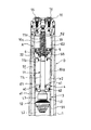
- FIG. 1 is a cross-sectional view showing a main part of a suspension device according to an embodiment of the present invention.
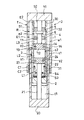
- FIG. 2 is a schematic diagram showing a suspension device according to an embodiment of the present invention.
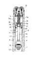
- FIG. 3 is a cross-sectional view showing a state in which the suspension device according to the embodiment of the present invention is most compressed.
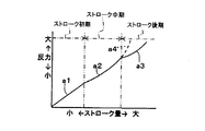
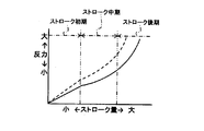
- FIG. 4 is a diagram showing the relationship between the stroke amount and the reaction force of the suspension device according to the embodiment of the present invention.
- FIG. 5 is a diagram illustrating the relationship between the stroke amount and the reaction force of the suspension device of the comparative example.
- FIG. 1 is a cross-sectional view showing a main part of a suspension device according to an embodiment of the present invention.
- FIG. 2 is a schematic diagram showing a suspension device according to an embodiment of the present invention.
- FIG. 3 is a cross-sectional view showing a state in which the suspension device according to the embodiment of the present invention is most compressed.
- subjected through each drawing shows the same component.
- the suspension device includes a shock absorber D and an air spring S1 that constantly biases the shock absorber D in the extending direction, as shown in FIG.
- the air spring S1 is made of compressed gas enclosed in an air chamber E1 whose volume expands and contracts as the shock absorber D expands and contracts.
- the suspension device also includes a volume expansion mechanism A that expands the volume of the air chamber E1 in accordance with an increase in the compression amount of the shock absorber D when the compression amount of the shock absorber D becomes equal to or greater than a predetermined amount.
- the suspension device is a front fork that suspends front wheels in a straddle-type vehicle such as a two-wheeled vehicle or a three-wheeled vehicle.
- the shock absorber D has a shock absorber body having an outer tube 1 connected to the vehicle body side and an inner tube 2 connected to the wheel side and inserted into the outer tube 1 so as to be able to appear and retract. T is provided.
- the vehicle body side opening (upper end in FIG. 2) of the shock absorber body T is closed by a cap member 10 attached to the outer tube 1, and the wheel side opening (lower end in FIG. 2) is closed by a bottom member 20. .
- the outside air side opening of the cylindrical gap t ⁇ b> 1 formed between the overlapping portions of the outer tube 1 and the inner tube 2 is held in series on the inner periphery of the wheel side end of the outer tube 1. It is closed by an annular oil seal C1 and an annular dust seal C2 that are in sliding contact with the outer peripheral surface.
- the shock absorber D includes a cylinder body 3 that is held in a state of being suspended from the cap member 10 and stands on the axial center portion of the shock absorber body T. Between the cylinder body 3 and the shock absorber body T, A reservoir R is formed in the upper part.
- the reservoir R stores a hydraulic fluid such as oil, water, and an aqueous solution to form a reservoir internal fluid chamber l1, and a gas is sealed above the hydraulic fluid to form a reservoir internal chamber e1. Yes.
- the cylinder body 3 includes a sub-cylinder 30 and a cylinder 31 that are continuous in the axial direction.
- the sub-cylinder 30 is held in a state where the base end portion is screwed with the cap member 10 and is suspended from the cap member 10.
- the cylinder 31 is screwed into the inner periphery of the tip portion 30 a of the sub cylinder 30 and is held by the cap member 10 via the sub cylinder 30.
- a free piston 4 slidably contacting the inner peripheral surface of the cylinder 31 is inserted into the cylinder 31 so as to be movable in the axial direction. Further, in the cylinder 31, a cylinder internal liquid chamber l2 that stores hydraulic fluid and a cylinder internal air chamber e2 that stores gas are formed. The cylinder internal liquid chamber l2 and the cylinder internal air chamber e2 are partitioned by a free piston 4.
- the shock absorber D is held by the bottom member 20 and is inserted into the in-cylinder liquid chamber l2 so as to be able to protrude and retract.
- the shock absorber D is held at the tip of the piston rod 21 and is in sliding contact with the inner peripheral surface of the cylinder 31.
- the piston 22 and the base member 12 divide the in-cylinder liquid chamber 12 into three chambers L1, L2, and L3 that are filled with hydraulic fluid.
- An extension side chamber L1 is formed below the piston 22, a pressure side chamber L2 is formed between the piston 22 and the base member 12, and a liquid reservoir chamber L3 is formed above the base member 12.
- the piston 22 is formed with an extension-side piston channel 23 and a pressure-side piston channel 24 that communicate the extension-side chamber L1 and the pressure-side chamber L2. Further, the piston 22 includes an expansion side damping valve V1 that provides resistance to the hydraulic fluid that passes through the expansion side piston flow path 23, and the hydraulic fluid passes through the compression side piston flow path 24 and passes from the compression side chamber L2 to the expansion side chamber L1. And a pressure side check valve V2 that only allows movement to the position.
- the base member 12 is formed with an extension-side base member flow path 13 and a pressure-side base member flow path 14 communicating the pressure-side chamber L2 and the liquid reservoir chamber L3. Further, the base member 12 includes an extension side check valve V3 that allows only hydraulic fluid to pass through the extension side base member flow path 13 and move from the liquid reservoir L3 to the pressure side chamber L2, and a pressure side base member. A pressure-side damping valve V4 that provides resistance to the hydraulic fluid passing through the flow path 14 is provided.
- the shock absorber D generates a damping force due to the resistance when the hydraulic fluid passes through the piston flow paths 23 and 24 and the base member flow paths 13 and 14 as the suspension device expands and contracts.
- the resistance due to the extension side check valve V3 and the pressure side check valve V2 is set to be smaller than the resistance due to the extension side damping valve V1 and the pressure side damping valve V4. Therefore, the damping force generated by the shock absorber D is mainly caused by the resistance of the expansion side damping valve V1 and the compression side damping valve V4.
- the valve structure for the shock absorber D to generate a damping force is not limited to the above, and a well-known configuration can be adopted as appropriate.
- the cylinder internal air chamber e2 formed in the cylinder 31 communicates with the reservoir internal air chamber e1 through a communication hole 32 formed in the sub cylinder 30, and together with the reservoir internal air chamber e1, the air chamber E1 is configured.
- the inner tube 2 when the shock absorber D is extended, the inner tube 2 is retracted from the outer tube 1 and the free piston 4 is moved downward in FIG. 1, so that the volume of the air chamber E1 is increased. Further, when the shock absorber D is compressed, the inner tube 2 enters the outer tube 1 and the free piston 4 moves upward in FIG. 1, so that the volume of the air chamber E1 is reduced.
- the air spring S1 functions as a suspension spring that urges the shock absorber D in the extending direction and elastically supports the vehicle body.
- an air valve 15 for the air chamber E1 is attached to the cap member 10.
- the reaction force of the air spring S1 can be adjusted by sucking and discharging gas into the air chamber E1 through the air valve 15.
- the suspension device houses a balance spring S3 that biases the shock absorber D in the contraction direction in the expansion side chamber L1 at the initial stroke of the suspension device with a small amount of compression of the shock absorber D. .
- the balance spring S3 cancels the reaction force of the air spring S1 (suspension spring) when the suspension device is fully extended. For this reason, even if an air spring is employed as a suspension spring that elastically supports the vehicle body, it is possible to suppress deterioration in the riding comfort of the vehicle.
- the base rod 11 includes a screw portion 11a having a screw groove formed on the outer periphery thereof and screwed into the inner periphery of the holding portion 10a of the cap member 10, and a small portion extending coaxially to the distal end side of the screw portion 11a.
- an attachment portion (not shown) on which the base member 12 is held on the outer periphery.
- a stopper 6 of a volume expanding mechanism A which will be described later, is screwed onto the outer periphery of the screw portion 11a, and the base rod 11 is prevented from loosening with a double nut structure. Further, the stopper 6 is provided with a return spring S5 that pushes the free piston 4 back to the liquid reservoir L3 side (lower side in FIG. 1) when the free piston 4 abuts.
- the free piston 4 includes an annular free piston main body 40, an annular inner peripheral seal 41 that is held on the inner periphery of the free piston main body 40 and slidably contacts the outer peripheral surface of the base rod 11, and an outer periphery of the free piston main body 40. And an annular outer peripheral seal 42 that is held in sliding contact with the inner peripheral surface of the cylinder 31.
- the free piston 4 partitions the liquid storage chamber L3 (cylinder internal liquid chamber l2) and the cylinder internal air chamber e2 (air chamber E1). can do.
- the shock absorber D is compressed and the free piston 4 moves upward in FIG. 1 and the inner peripheral seal 41 reaches the small outer diameter portion 11b as shown in FIG. 3, the return spring S5 is free piston. 4 and a gap is formed between the inner peripheral seal 41 and the small outer diameter portion 11b. For this reason, the hydraulic fluid in the liquid storage chamber L3 can move to the reservoir R through the clearance between the inner peripheral seal 41 and the small outer diameter portion 11b and the communication hole 32.
- the free piston 4 moves to the liquid reservoir chamber L3 side (lower side in FIG. 3) by the reaction force of the return spring S5. Pushed back. As a result, the free piston 4 moves to a position where the inner peripheral seal 41 is in sliding contact with the outer peripheral surface of the large outer diameter portion 11c.
- volume expansion mechanism A will be described.
- the volume expansion mechanism A expands the volume of the air chamber E1 according to the increase in the compression amount of the shock absorber D when the compression amount of the shock absorber D becomes equal to or larger than a predetermined amount.
- the volume expansion mechanism A includes a sub-cylinder 30, an auxiliary chamber E2 formed in the sub-cylinder 30, and a movable partition wall 5 that slidably contacts the inner peripheral surface of the sub-cylinder 30 and divides the air chamber E1 and the auxiliary chamber E2.
- the compression amount of the air spring S2 as an urging means for urging the movable partition wall 5 toward the air chamber E1 (the lower side in FIG. 1) and the shock absorber D is less than a predetermined amount
- the movable partition wall 5 And a stopper 6 for preventing movement to the chamber E1 side (lower side in FIG. 1).
- the air spring S2 is a compressed gas sealed in the auxiliary chamber E2.
- the internal pressure of the auxiliary chamber E2 is set so that the movable partition wall 5 moves to the auxiliary chamber E2 side (upper side in FIG. 1) when the compression amount of the shock absorber D becomes a predetermined amount or more.
- an air valve 16 for the auxiliary chamber E2 is attached to the cap member 10, and the reaction force of the air spring S2, that is, the movable partition wall 5 is obtained by sucking and discharging gas into the auxiliary chamber E2 through the air valve 16. The force that urges the air chamber E1 toward the air chamber E1 can be adjusted.
- FIG. 4 is a diagram showing the relationship between the stroke amount and the reaction force of the suspension device according to the embodiment of the present invention.
- the reaction force characteristic of the suspension device at this time is a combined characteristic of the balance spring S3 and the air spring S1.
- the balance spring S3 of this embodiment is a coil spring, the reaction force characteristic at the initial stroke of the suspension device is substantially linear as shown by a solid line a1 in FIG.
- the movable partition wall 5 is maintained in contact with the stopper 6. It does not move.
- the reaction force characteristic of the suspension device at this time is only the characteristic of the air spring S1.
- the reaction force characteristic in the middle of the stroke of the suspension device is a non-linear characteristic as shown by a solid line a2 in FIG.
- the movable partition wall 5 is on the auxiliary chamber E2 side (upper side in FIG. 1) against the urging force of the air spring S2.
- the reaction force characteristic of the suspension device at this time is a combined characteristic of the air spring S1 and the air spring S2, it becomes a non-linear characteristic as shown by a solid line a3 in FIG.
- the stroke stage of the suspension is divided into the initial stroke, middle stroke and late stroke according to the stroke amount of the suspension (compression amount of the shock absorber D).
- the threshold value can be arbitrarily set.
- the reaction force characteristic of the suspension device is the combined characteristic of the balance spring and the air spring Become. Therefore, the reaction force characteristic at the initial stroke of the suspension device is substantially linear.
- the reaction force characteristic of the suspension system is a characteristic of only the air spring. Therefore, the reaction force characteristics of the suspension device in the middle and later strokes are nonlinear characteristics.
- the air spring suspension spring
- the reaction force in the latter half of the stroke may be excessive as shown by the broken line in FIG.
- the suspension device includes a shock absorber D and an air spring S1 that constantly biases the shock absorber D in the extending direction.
- the air spring S1 expands and contracts as the shock absorber D expands and contracts. It consists of the compressed gas enclosed with the air chamber E1.
- the suspension device according to the present embodiment has a volume expansion mechanism A that expands the volume of the air chamber E1 in accordance with an increase in the compression amount of the shock absorber D when the compression amount of the shock absorber D becomes equal to or greater than a predetermined amount. Is further provided.
- the volume expansion mechanism A expands the volume of the air chamber E1 with an increase in the compression amount of the shock absorber D and reduces the compression amount of the shock absorber D only when the compression amount of the shock absorber D is equal to or greater than a predetermined amount. Accordingly, the volume of the air chamber E1 is reduced. Since the reaction force of the air spring S1 decreases as the volume of the air chamber E1 increases, by providing the volume expansion mechanism A, it is possible to cut the reaction force in the latter half of the stroke of the suspension device according to the stroke amount.
- the reaction force in the latter half of the stroke may be excessive as described above. is there.
- the reaction force at the end of the stroke is suppressed more than the reaction force when the volume expansion mechanism A indicated by the broken line a4 is not provided, as indicated by the solid line a3 in FIG. The Therefore, even if the reaction force in the middle of the stroke is increased, it is possible to suppress the reaction force in the latter half of the stroke from becoming excessive.
- the volume expansion mechanism A includes a sub-cylinder 30, an auxiliary chamber E2 formed in the sub-cylinder 30, and a movable partition wall that slidably contacts the inner peripheral surface of the sub-cylinder 30 and divides the air chamber E1 and the auxiliary chamber E2.
- the movable partition wall 5 moves to the auxiliary chamber E2 side when the compression amount of the shock absorber D becomes a predetermined amount or more.
- the amount of movement of the movable partition 5 increases as the compression amount of the shock absorber D increases. That is, the movable partition wall 5 moves greatly toward the auxiliary chamber E2 as the compression amount of the shock absorber D increases.
- the volume of the air chamber E1 can be easily increased as the compression amount of the shock absorber D increases.
- volume expansion mechanism A moves the movable partition wall 5 to the air chamber E1 side when the compression amount of the air spring S2 that urges the movable partition wall 5 toward the air chamber E1 and the shock absorber D is less than a predetermined amount. And a stopper 6 for preventing this.
- the biasing force of the air spring S2 is set so that the movable partition wall 5 moves toward the auxiliary chamber E2 against the biasing force of the air spring S2 when the compression amount of the shock absorber D reaches a predetermined amount.
- the volume of the air chamber E1 can be increased as the compression amount of the shock absorber D increases. Therefore, it is possible to simplify the configuration for expanding the volume of the air chamber E1 as the compression amount of the shock absorber D increases.
- stopper 6 it is possible to easily move the movable partition wall 5 only when the compression amount of the shock absorber D exceeds a predetermined amount.
- the air spring S2 as the urging means is made of compressed gas sealed in the auxiliary chamber E2.
- the means for urging the movable partition wall 5 toward the air chamber E1 is a coil spring or the like. Further, by sucking and discharging the gas into the auxiliary chamber E2, the urging force (reaction force) of the air spring S2 can be easily adjusted, and the timing at which the movable partition wall 5 starts to move can be easily adjusted.
- the shock absorber D includes a shock absorber body T having an outer tube 1 and an inner tube 2 inserted into the outer tube 1 so as to be able to appear and retract, and the sub cylinder 30 is accommodated in the shock absorber body T. At the same time, an air chamber E1 is formed.
- volume expansion mechanism A and the air spring S1 can be accommodated in the shock absorber body T, even if the volume expansion mechanism A is provided, an increase in the size of the suspension device can be suppressed.
- the suspension device is a front fork that suspends a front wheel in a saddle-type vehicle such as a two-wheeled vehicle or a three-wheeled vehicle, but a rear cushion unit that suspends a rear wheel of the saddle-type vehicle.
- a suspension device for another vehicle may be a suspension device for another vehicle.
- the suspension device is set to an inverted type in which the outer tube 1 is disposed on the vehicle body side and the inner tube 2 is disposed on the wheel side.
- the inner tube 2 may be arranged on the vehicle body side and the outer tube 1 may be set upright on the wheel side, and the configuration of the suspension device can be changed as appropriate.
- the shock absorber D is set to an inverted type in which the cylinder 31 is disposed on the vehicle body side and the piston rod 21 is disposed on the wheel side.
- the cylinder 31 may be arranged on the wheel side and the piston rod 21 may be set upright so that the piston rod 21 is arranged on the vehicle body side, and the configuration of the shock absorber D constituting the suspension device can be changed as appropriate. is there.
- the volume expansion mechanism A is accommodated in the shock absorber main body T.
- the present invention is not limited to this, and the sub tank 30 may be externally attached to the shock absorber main body T.
- the subtank 30 and the cylinder 31 are formed as a different body, they may be integrally formed.
- the volume expansion mechanism A is provided with the movable partition 5, and the volume of the air chamber E1 can be expanded by moving the movable partition 5 to the auxiliary chamber E2 side.
- the volume of the air chamber E1 may be expanded by a method other than 5.
- the movable partition 5 which comprises the volume expansion mechanism A is urged
- the volume expansion mechanism A includes a sensor that detects the compression amount of the shock absorber D, a motor that drives the movable partition wall 5, a motion conversion mechanism that converts the rotational motion of the motor into a linear motion of the movable partition wall 5, and a sensor.
- a control device that drives the motor based on the detected value may be provided, and the motor may be operated according to the compression amount of the shock absorber D to move the movable partition wall 5.
- the air spring S2 is used as means for biasing the movable partition wall 5, but the biasing means may be a coil spring.
Landscapes
- Engineering & Computer Science (AREA)
- General Engineering & Computer Science (AREA)
- Mechanical Engineering (AREA)
- Fluid-Damping Devices (AREA)
Abstract
懸架装置は、緩衝器と、緩衝器の伸縮に伴い容積が拡大、縮小するエア室に封入された圧縮気体からなり、緩衝器を常に伸長方向に附勢するエアばねと、緩衝器の圧縮量が所定量以上となったときに、緩衝器の圧縮量の増加に応じてエア室の容積を拡大させる容積拡大機構と、を備える。
Description
本発明は、懸架装置に関するものである。
一般的に、懸架装置は、自動車や二輪車等の車体と車輪との間に介装されており、減衰力を発生する緩衝器と、緩衝器を伸長方向に附勢して車体を弾性支持する懸架ばねとを備えている。これにより、懸架装置は、路面凹凸による衝撃を懸架ばねで吸収するとともに、この衝撃吸収に伴う懸架ばねの伸縮運動を緩衝器で抑制し、路面凹凸による衝撃が車体に伝達されることを抑制することができる。
例えば、JP2010-185572Aに開示されている懸架装置は、二輪車や三輪車等の鞍乗型車両において前輪を懸架するフロントフォークである。
上記の懸架装置の緩衝器は、アウターチューブと、アウターチューブ内に出没可能に挿入されるインナーチューブと、を有する緩衝器本体を備えている。また、上記の懸架装置の懸架ばねは、緩衝器本体内に収容されているエアばねである。エアばねは、緩衝器本体内に形成されて緩衝器の伸縮に伴い容積が拡大、縮小するエア室に封入された圧縮気体からなり、常に緩衝器を伸長方向に附勢している。
このように、懸架ばねがエアばねである場合は、懸架ばねがコイルスプリングである場合よりも懸架装置を軽量化できるが、緩衝器の圧縮量が少ない懸架装置のストローク初期では、懸架装置が速やかに圧縮されず、車両の乗り心地を悪化させる虞がある。このため、上記の懸架装置は、懸架装置のストローク初期においてエアばね(懸架ばね)の反力を相殺するバランスばねを備え、これにより、車両の乗り心地が悪化することを抑制している。
上記の懸架装置では、緩衝器の圧縮量が小さく、バランスばねが働くストローク初期の反力特性は、バランスばねとエアばねとの合成特性となる。ここで、バランスばねはコイルスプリングであるので、懸架装置の反力特性は略線形特性となる。また、緩衝器の圧縮量が大きく、バランスばねが働かなくなるストローク中期及びストローク後期の反力特性は、エアばねのみの特性となる。ここで、気体の圧力と体積とは一定温度下で反比例の関係にあるので、懸架装置の反力特性は非線形特性となる。このため、上記の懸架装置において、ストローク中期の反力が大きくなるようにエアばね(懸架ばね)を調整すると、ストローク後期の反力が過大となる虞がある。
本発明は、上記の問題点に鑑みてなされたものであり、緩衝器を常に伸長方向に附勢するエアばねを備える懸架装置において、ストローク中期の反力を大きくしたとしても、ストローク後期の反力が過大となることを抑制することを目的とする。
本発明のある態様によれば、懸架装置であって、緩衝器と、前記緩衝器の伸縮に伴い容積が拡大、縮小するエア室に封入された圧縮気体からなり、前記緩衝器を常に伸長方向に附勢するエアばねと、前記緩衝器の圧縮量が所定量以上となったときに、前記緩衝器の圧縮量の増加に応じて前記エア室の容積を拡大させる容積拡大機構と、を備える懸架装置が提供される。
以下、添付図面を参照しながら本発明の実施形態について説明する。
図1は、本発明の実施形態に係る懸架装置の主要部を示す断面図である。図2は、本発明の実施形態に係る懸架装置を示す模式図である。図3は、本発明の実施形態に係る懸架装置が最圧縮された状態を示す断面図である。なお、各図面を通して付された同じ符号は、同じ部品を示す。
本実施形態に係る懸架装置は、図1に示すように、緩衝器Dと、緩衝器Dを常に伸長方向に附勢するエアばねS1とを備える。エアばねS1は、緩衝器Dの伸縮に伴い容積が拡大、縮小するエア室E1に封入された圧縮気体からなる。また、懸架装置は、緩衝器Dの圧縮量が所定量以上となったときに、緩衝器Dの圧縮量の増加に応じてエア室E1の容積を拡大させる容積拡大機構Aを備えている。
以下、詳細に説明する。本実施形態に係る懸架装置は、二輪車や三輪車等の鞍乗型車両において前輪を懸架するフロントフォークである。緩衝器Dは、図2に示すように、車体側に連結されるアウターチューブ1と、車輪側に連結されてアウターチューブ1内に出没可能に挿入されるインナーチューブ2と、を有する緩衝器本体Tを備えている。
緩衝器本体Tの車体側開口(図2における上端)は、アウターチューブ1に取り付けられるキャップ部材10で塞がれ、車輪側開口(図2における下端)は、ボトム部材20で塞がれている。また、アウターチューブ1とインナーチューブ2との重複部の間に形成される筒状隙間t1の外気側開口は、アウターチューブ1の車輪側端部の内周に直列に保持されてインナーチューブ2の外周面に摺接する環状のオイルシールC1と環状のダストシールC2とで塞がれている。これにより、緩衝器本体T内が外気側と区画され、緩衝器本体T内に収容される気体や液体が緩衝器本体T外に流出することを防ぐことができる。
また、緩衝器Dは、キャップ部材10に吊り下げられた状態で保持されて緩衝器本体Tの軸心部に起立するシリンダ体3を備えており、シリンダ体3と緩衝器本体Tとの間にリザーバRが形成されている。リザーバRには、油、水、水溶液等の液体からなる作動液が貯留されてリザーバ内液室l1が形成されるとともに、作動液の上側に気体が封入されてリザーバ内気室e1が形成されている。
シリンダ体3は、図1に示すように、軸方向に連なるサブシリンダ30とシリンダ31とからなる。サブシリンダ30は、基端部がキャップ部材10と螺合し、キャップ部材10に吊り下げられた状態で保持されている。また、シリンダ31は、サブシリンダ30の先端部30aの内周と螺合し、サブシリンダ30を介してキャップ部材10に保持されている。
シリンダ31内には、図2に示すように、シリンダ31の内周面に摺接するフリーピストン4が、軸方向に移動可能に挿入されている。また、シリンダ31内には、作動液が収容されるシリンダ内液室l2と、気体が収容されるシリンダ内気室e2とが形成されている。シリンダ内液室l2とシリンダ内気室e2とは、フリーピストン4で区画されている。
また、緩衝器Dは、ボトム部材20に保持されてシリンダ内液室l2内に出没可能に挿入されるピストンロッド21と、ピストンロッド21の先端に保持されてシリンダ31の内周面に摺接するピストン22と、キャップ部材10に保持されてシリンダ31のピストンロッド21と反対側の軸心部に起立するベースロッド11と、ベースロッド11の先端に保持されてシリンダ31の内周に固定されるベース部材12と、を備えている。そして、ピストン22とベース部材12とが、シリンダ内液室l2を、作動液が充填される三つの部屋L1、L2、L3に区画している。ピストン22の下側には伸側室L1が形成され、ピストン22とベース部材12との間には圧側室L2が形成され、ベース部材12の上側には液溜室L3が形成されている。
ピストン22には、伸側室L1と圧側室L2とを連通する伸側のピストン流路23と圧側のピストン流路24とが形成される。また、ピストン22には、伸側のピストン流路23を通過する作動液に抵抗を与える伸側減衰バルブV1と、作動液が圧側のピストン流路24を通過して圧側室L2から伸側室L1へ移動することのみを許容する圧側チェック弁V2とが設けられている。
ベース部材12には、圧側室L2と液溜室L3とを連通する伸側のベース部材流路13と圧側のベース部材流路14とが形成される。また、ベース部材12には、作動液が伸側のベース部材流路13を通過して液溜室L3から圧側室L2へ移動することのみを許容する伸側チェック弁V3と、圧側のベース部材流路14を通過する作動液に抵抗を与える圧側減衰バルブV4とが設けられている。
上記の構成によれば、インナーチューブ2がアウターチューブ1から退出してピストンロッド21がシリンダ31から退出する緩衝器D(懸架装置)の伸長時には、ピストン22で加圧された伸側室L1の作動液が、伸側のピストン流路23を通過して圧側室L2に移動する。このとき、シリンダ31から退出したピストンロッド21の体積分の作動液が、伸側のベース部材流路13を通過して液溜室L3から圧側室L2に移動するので、フリーピストン4が図2における下側に移動する。
また、インナーチューブ2がアウターチューブ1内に進入してピストンロッド21がシリンダ31内に進入する緩衝器D(懸架装置)の圧縮時には、ピストン22で加圧された圧側室L2の作動液が、圧側のピストン流路24を通過して伸側室L1に移動する。このとき、シリンダ31内に進入したピストンロッド21の体積分の作動液が、圧側のベース部材流路14を通過して圧側室L2から液溜室L3に移動するので、フリーピストン4が図2における上側に移動する。
これにより、緩衝器Dは、懸架装置の伸縮に伴い、作動液がピストン流路23、24及びベース部材流路13、14を通過する際の抵抗に起因する減衰力を発生させる。なお、本実施形態では、伸側チェック弁V3や圧側チェック弁V2による抵抗は、伸側減衰バルブV1や圧側減衰バルブV4による抵抗よりも小さくなるように設定されている。したがって、緩衝器Dが発生させる減衰力は、主に伸側減衰バルブV1と圧側減衰バルブV4との抵抗に起因する。しかしながら、緩衝器Dが減衰力を発生させるためのバルブ構造は、上記の限りではなく、適宜周知の構成を採用することが可能である。
シリンダ31内に形成されるシリンダ内気室e2は、図1に示すように、サブシリンダ30に形成される連通孔32を介してリザーバ内気室e1と連通しており、リザーバ内気室e1とともにエア室E1を構成している。
上記の構成によれば、緩衝器Dの伸長時には、インナーチューブ2がアウターチューブ1から退出してフリーピストン4が図1における下側に移動するので、エア室E1の容積が拡大する。また、緩衝器Dの圧縮時には、インナーチューブ2がアウターチューブ1内に進入してフリーピストン4が図1における上側に移動するので、エア室E1の容積が縮小する。
エア室E1には圧縮気体が封入され、封入された圧縮気体はエアばねS1として機能している。そして、エアばねS1は、緩衝器Dを常に伸長方向に附勢して車体を弾性支持する懸架ばねとして機能している。
キャップ部材10には、図1に示すように、エア室E1用のエアバルブ15が取り付けられている。エアバルブ15を介してエア室E1内に気体を吸排することで、エアばねS1の反力を調整することができる。
また、懸架装置は、図2に示すように、緩衝器Dの圧縮量が少ない懸架装置のストローク初期において、緩衝器Dを収縮方向に附勢するバランスばねS3を伸側室L1に収容している。バランスばねS3は、懸架装置の最伸長時には、エアばねS1(懸架ばね)の反力を相殺する。このため、車体を弾性支持する懸架ばねとしてエアばねを採用したとしても、車両の乗り心地が悪化することを抑制することが可能となる。
また、緩衝器Dの伸側室L1には、懸架装置の最伸長時に圧縮されて所定の反力を発生するリバウンドばねS4が設けられる。これにより、懸架装置の最伸長時の衝撃を吸収することができる。
ベースロッド11は、図1に示すように、外周に螺子溝が形成されてキャップ部材10の保持部10aの内周に螺合する螺子部11aと、螺子部11aの先端側に同軸に延びる小外径部11bと、小外径部11bの先端側に同軸に延びて外径が小外径部11bよりも大きく形成される大外径部11cと、大外径部11cの先端側に同軸に延びて外周にベース部材12が保持される取り付け部(図示せず)と、を備えている。
螺子部11aの外周には、後述する容積拡大機構Aのストッパ6が螺合しており、ダブルナット構造でベースロッド11の緩み止めをしている。また、ストッパ6には、フリーピストン4が当接したときに、フリーピストン4を液溜室L3側(図1における下側)に押し戻すリターンばねS5が設けられている。
フリーピストン4は、環状に形成されるフリーピストン本体40と、フリーピストン本体40の内周に保持されてベースロッド11の外周面に摺接する環状の内周シール41と、フリーピストン本体40の外周に保持されてシリンダ31の内周面に摺接する環状の外周シール42と、を備えている。
内周シール41が大外径部11cの外周面に摺接している場合は、フリーピストン4は、液溜室L3(シリンダ内液室l2)とシリンダ内気室e2(エア室E1)とを区画することができる。しかし、緩衝器Dが圧縮されてフリーピストン4が図1における上側に移動し、図3に示すように、内周シール41が小外径部11bに達した場合は、リターンばねS5がフリーピストン4で圧縮されるとともに、内周シール41と小外径部11bとの間に隙間が生じる。このため、液溜室L3の作動液が、内周シール41と小外径部11bとの間の隙間及び連通孔32を通過してリザーバRに移動することができる。
また、緩衝器Dが圧縮工程から伸長工程に転じて、液溜室L3の内圧が下がると、リターンばねS5の反力により、フリーピストン4が液溜室L3側(図3における下側)に押し戻される。これにより、内周シール41が大外径部11cの外周面に摺接する位置までフリーピストン4が移動する。
続いて、容積拡大機構Aについて説明する。
容積拡大機構Aは、緩衝器Dの圧縮量が所定量以上となったときに、緩衝器Dの圧縮量の増加に応じて、エア室E1の容積を拡大させる。容積拡大機構Aは、サブシリンダ30と、サブシリンダ30内に形成される補助室E2と、サブシリンダ30の内周面に摺接してエア室E1と補助室E2とを区画する可動隔壁5と、可動隔壁5をエア室E1側(図1における下側)に附勢する附勢手段としてのエアばねS2と、緩衝器Dの圧縮量が所定量に満たないときに、可動隔壁5がエア室E1側(図1における下側)に移動することを防止するストッパ6と、を備えている。
エアばねS2は、補助室E2内に封入された圧縮気体である。補助室E2の内圧は、緩衝器Dの圧縮量が所定量以上となったときに、可動隔壁5が補助室E2側(図1における上側)に移動するように設定されている。また、キャップ部材10には、補助室E2用のエアバルブ16が取り付けられており、エアバルブ16を介して補助室E2内に気体を吸排することで、エアばねS2の反力、すなわち、可動隔壁5をエア室E1側に附勢する力を調整することができる。
続いて、容積拡大機構Aの動作について図4を参照しながら説明する。図4は、本発明の実施形態に係る懸架装置のストローク量と反力との関係を示す図である。
懸架装置のストローク初期、すなわち、緩衝器Dの圧縮量が所定量に達しておらず、バランスばねS3が働く状態では、可動隔壁5は、エアばねS2の附勢力でストッパ6に押し付けられているので、ストッパ6に当接した状態に維持されて動かない。このときの懸架装置の反力特性は、バランスばねS3とエアばねS1との合成特性となる。ここで、本実施形態のバランスばねS3はコイルスプリングであるので、懸架装置のストローク初期の反力特性は、図4に実線a1で示すように、略線形特性となる。
また、懸架装置のストローク中期、すなわち、緩衝器Dの圧縮量が所定量に達しておらず、かつ、バランスばねS3が働かない状態では、可動隔壁5は、ストッパ6に当接した状態に維持されて動かない。このときの懸架装置の反力特性は、エアばねS1のみの特性となる。ここで、気体の圧力と体積とは一定温度下で反比例の関係にあるので、懸架装置のストローク中期の反力特性は、図4に実線a2で示すように、非線形特性となる。
さらに、懸架装置のストローク後期、すなわち、緩衝器Dの圧縮量が所定量以上となる状態では、可動隔壁5は、エアばねS2の附勢力に抗して補助室E2側(図1における上側)に移動してストッパ6から離れる。そして、緩衝器Dの圧縮量が大きくなるほど、可動隔壁5の移動量も大きくなるので、緩衝器Dの圧縮量が大きくなるほど、エア室E1の容積が拡大する。このときの懸架装置の反力特性は、エアばねS1とエアばねS2との合成特性となるので、図4に実線a3で示すように、非線形特性となる。
なお、懸架装置のストローク段階を、懸架装置のストローク量(緩衝器Dの圧縮量)に応じて、ストローク量が小さい方からストローク初期、ストローク中期、ストローク後期に区分けしているが、各ストローク段階の閾値は任意に設定することが可能である。
次に、本実施形態に係る懸架装置の作用効果について、比較例を参照しながら説明する。
容積拡大機構Aを備えない懸架装置のストローク量と反力との関係は、図5に実線で示すようになる。
容積拡大機構Aを備えない場合は、懸架装置のストローク初期、すなわち、緩衝器の圧縮量が小さくバランスばねが働く状態では、懸架装置の反力特性は、バランスばねとエアばねとの合成特性となる。したがって、懸架装置のストローク初期の反力特性は、略線形特性となる。
また、懸架装置のストローク中期及びストローク後期、すなわち、緩衝器の圧縮量が大きくなりバランスばねが働かなくなる状態では、懸架装置の反力特性は、エアばねのみの特性となる。したがって、懸架装置のストローク中期及びストローク後期の反力特性は、非線形特性となる。ここで、懸架装置のストローク中期の反力が大きくなるようにエアばね(懸架ばね)を調整すると、図5に破線で示すように、ストローク後期の反力が過大となる虞がある。
本実施形態に係る懸架装置は、緩衝器Dと、緩衝器Dを常に伸長方向に附勢するエアばねS1とを備え、エアばねS1は、緩衝器Dの伸縮に伴い容積が拡大、縮小するエア室E1に封入された圧縮気体からなる。そして、本実施形態に係る懸架装置は、緩衝器Dの圧縮量が所定量以上となったときに、緩衝器Dの圧縮量の増加に応じてエア室E1の容積を拡大させる容積拡大機構Aを、さらに備えている。
容積拡大機構Aは、緩衝器Dの圧縮量が所定量以上である場合にのみ、緩衝器Dの圧縮量の増加に伴いエア室E1の容積を拡大し、緩衝器Dの圧縮量の減少に伴いエア室E1の容積を縮小させる。エアばねS1の反力は、エア室E1の容積が大きくなるほど小さくなるので、容積拡大機構Aを備えることで、懸架装置のストローク後期の反力をストローク量に応じてカットすることができる。
懸架装置のストローク中期の反力が大きくなるようにエアばねの反力を調整した場合、容積拡大機構Aを備えない懸架装置では、上記のように、ストローク後期の反力が過大となる虞がある。これに対して、本実施形態に係る懸架装置では、ストローク後期の反力が、図4に実線a3で示すように、破線a4で示す容積拡大機構Aを備えない場合の反力よりも抑制される。したがって、ストローク中期の反力を大きくしたとしても、ストローク後期の反力が過大となることを抑制することが可能となる。
また、容積拡大機構Aは、サブシリンダ30と、サブシリンダ30内に形成される補助室E2と、サブシリンダ30の内周面に摺接してエア室E1と補助室E2とを区画する可動隔壁5とを備え、可動隔壁5は、緩衝器Dの圧縮量が所定量以上となったときに、補助室E2側に移動する。可動隔壁5の移動量は、上記緩衝器Dの圧縮量の増加に応じて大きくなる。つまり、可動隔壁5は、緩衝器Dの圧縮量が大きくなるほど、補助室E2側に大きく移動する。
このように、可動隔壁5を備えることで、緩衝器Dの圧縮量の増加に応じてエア室E1の容積を大きくすることが容易に可能となる。
また、容積拡大機構Aは、可動隔壁5をエア室E1側に附勢するエアばねS2と、緩衝器Dの圧縮量が所定量に満たないときに、可動隔壁5がエア室E1側に移動することを防止するストッパ6とを備えている。
つまり、緩衝器Dの圧縮量が所定量に達したときに、エアばねS2の附勢力に抗して可動隔壁5が補助室E2側に移動するように、エアばねS2の附勢力を設定することで、緩衝器Dの圧縮量の増加に応じてエア室E1の容積を拡大させることができる。よって、緩衝器Dの圧縮量の増加に応じてエア室E1の容積を拡大させるための構成を簡易にすることが可能となる。
また、ストッパ6を備えることで、緩衝器Dの圧縮量が所定量以上となったときにのみ、可動隔壁5を移動させることが容易に可能となる。
また、附勢手段としてのエアばねS2は、補助室E2内に封入された圧縮気体からなる。
したがって、可動隔壁5をエア室E1側に附勢する手段がコイルスプリング等である場合よりも懸架装置を軽量化することが可能となる。また、補助室E2内に気体を吸排することで、エアばねS2の附勢力(反力)を容易に調整することができるとともに、可動隔壁5が動き始めるタイミングを容易に調整することができる。
また、緩衝器Dは、アウターチューブ1と、アウターチューブ1内に出没可能に挿入されるインナーチューブ2と、を有する緩衝器本体Tを備え、緩衝器本体T内にサブシリンダ30が収容されるとともにエア室E1が形成されている。
つまり、緩衝器本体T内に容積拡大機構A及びエアばねS1を収容することができるので、容積拡大機構Aを備えていても、懸架装置の大型化を抑制することができる。
以上、本発明の実施形態について説明したが、上記実施形態は本発明の適用例の一部を示したに過ぎず、本発明の技術的範囲を上記実施形態の具体的構成に限定する趣旨ではない。
例えば、上記実施形態においては、懸架装置が、二輪車や三輪車等の鞍乗型車両において前輪を懸架するフロントフォークであるとしたが、鞍乗型車両の後輪を懸架するリアクッションユニットであってもよく、他の車両用の懸架装置であってもよい。
また、上記実施形態においては、懸架装置が、アウターチューブ1が車体側に配置され、インナーチューブ2が車輪側に配置される倒立型に設定されている。しかしながら、インナーチューブ2が車体側に配置され、アウターチューブ1が車輪側に配置される正立型に設定されてもよく、懸架装置の構成は適宜変更することが可能である。
また、上記実施形態においては、緩衝器Dが、シリンダ31が車体側に配置され、ピストンロッド21が車輪側に配置される倒立型に設定されている。しかしながら、シリンダ31が車輪側に配置され、ピストンロッド21が車体側に配置される正立型に設定されてもよく、懸架装置を構成する緩衝器Dの構成は、適宜変更することが可能である。
また、上記実施形態においては、容積拡大機構Aが緩衝器本体T内に収容されているが、この限りではなく、サブタンク30が緩衝器本体Tに外付けされていてもよい。また、上記実施形態において、サブタンク30とシリンダ31とは、別体として形成されているが、一体形成されてもよい。
また、上記実施形態においては、容積拡大機構Aが可動隔壁5を備えており、可動隔壁5を補助室E2側に移動させることにより、エア室E1の容積を拡大させることができるが、可動隔壁5以外の方法によってエア室E1の容積を拡大させてもよい。
また、上記実施形態においては、容積拡大機構Aを構成する可動隔壁5が、エアばねS2でエア室E1側に附勢され、緩衝器Dの圧縮量の増加に応じて補助室E2側に移動するので、エア室E1の容積を拡大させることが可能となる。しかしながら、容積拡大機構Aが、緩衝器Dの圧縮量を検知するセンサと、可動隔壁5を駆動するモータと、モータの回転運動を可動隔壁5の直線運動に変換する運動変換機構と、センサで検知した値を基にモータを駆動する制御装置を備え、緩衝器Dの圧縮量に応じてモータを作動させ、可動隔壁5を移動させるようにしてもよい。
また、上記実施形態においては、可動隔壁5を附勢する手段としてエアばねS2を用いているが、付勢手段はコイルスプリングであってもよい。
本願は2012年10月9日に日本国特許庁に出願された特願2012-223767に基づく優先権を主張し、この出願の全ての内容は参照により本明細書に組み込まれる。
Claims (5)
- 懸架装置であって、
緩衝器と、
前記緩衝器の伸縮に伴い容積が拡大、縮小するエア室に封入された圧縮気体からなり、前記緩衝器を常に伸長方向に附勢するエアばねと、
前記緩衝器の圧縮量が所定量以上となったときに、前記緩衝器の圧縮量の増加に応じて前記エア室の容積を拡大させる容積拡大機構と、
を備える懸架装置。 - 請求項1に記載の懸架装置であって、
前記容積拡大機構は、
サブシリンダと、
前記サブシリンダ内に形成される補助室と、
前記サブシリンダの内周面に摺接して前記エア室と前記補助室とを区画する可動隔壁と、
を備え、
前記可動隔壁は、前記緩衝器の圧縮量が所定量以上となったときに、前記緩衝器の圧縮量が増加するほど、前記補助室側に大きく移動する懸架装置。 - 請求項2に記載の懸架装置であって、
前記容積拡大機構は、
前記可動隔壁を前記エア室側に附勢する附勢手段と、
前記緩衝器の圧縮量が所定量に満たないときに、前記可動隔壁が前記エア室側に移動することを防止するストッパと、
をさらに備える懸架装置。 - 請求項3に記載の懸架装置であって、
前記附勢手段は、前記補助室に封入された圧縮気体からなる懸架装置。 - 請求項2に記載の懸架装置であって、
前記緩衝器は、アウターチューブと、前記アウターチューブ内に出没可能に挿入されるインナーチューブと、を有する緩衝器本体を備え、
前記緩衝器本体内に、前記サブシリンダが収容されるとともに前記エア室が形成される懸架装置。
Priority Applications (1)
| Application Number | Priority Date | Filing Date | Title |
|---|---|---|---|
| US14/429,628 US9765842B2 (en) | 2012-10-09 | 2013-10-04 | Suspension device |
Applications Claiming Priority (2)
| Application Number | Priority Date | Filing Date | Title |
|---|---|---|---|
| JP2012223767A JP5936271B2 (ja) | 2012-10-09 | 2012-10-09 | 懸架装置 |
| JP2012-223767 | 2012-10-09 |
Publications (1)
| Publication Number | Publication Date |
|---|---|
| WO2014057897A1 true WO2014057897A1 (ja) | 2014-04-17 |
Family
ID=50477364
Family Applications (1)
| Application Number | Title | Priority Date | Filing Date |
|---|---|---|---|
| PCT/JP2013/077173 Ceased WO2014057897A1 (ja) | 2012-10-09 | 2013-10-04 | 懸架装置 |
Country Status (3)
| Country | Link |
|---|---|
| US (1) | US9765842B2 (ja) |
| JP (1) | JP5936271B2 (ja) |
| WO (1) | WO2014057897A1 (ja) |
Families Citing this family (27)
| Publication number | Priority date | Publication date | Assignee | Title |
|---|---|---|---|---|
| US20100170760A1 (en) | 2009-01-07 | 2010-07-08 | John Marking | Remotely Operated Bypass for a Suspension Damper |
| US10060499B2 (en) | 2009-01-07 | 2018-08-28 | Fox Factory, Inc. | Method and apparatus for an adjustable damper |
| US9452654B2 (en) | 2009-01-07 | 2016-09-27 | Fox Factory, Inc. | Method and apparatus for an adjustable damper |
| US11306798B2 (en) | 2008-05-09 | 2022-04-19 | Fox Factory, Inc. | Position sensitive suspension damping with an active valve |
| US10047817B2 (en) | 2009-01-07 | 2018-08-14 | Fox Factory, Inc. | Method and apparatus for an adjustable damper |
| US10036443B2 (en) | 2009-03-19 | 2018-07-31 | Fox Factory, Inc. | Methods and apparatus for suspension adjustment |
| US12491961B2 (en) | 2008-11-25 | 2025-12-09 | Fox Factory, Inc. | Seat post |
| US11299233B2 (en) | 2009-01-07 | 2022-04-12 | Fox Factory, Inc. | Method and apparatus for an adjustable damper |
| US9038791B2 (en) | 2009-01-07 | 2015-05-26 | Fox Factory, Inc. | Compression isolator for a suspension damper |
| US12122205B2 (en) * | 2009-01-07 | 2024-10-22 | Fox Factory, Inc. | Active valve for an internal bypass |
| US9528565B2 (en) | 2014-09-16 | 2016-12-27 | Fox Factory, Inc. | Adjustable internal bypass |
| EP2312180B1 (en) | 2009-10-13 | 2019-09-18 | Fox Factory, Inc. | Apparatus for controlling a fluid damper |
| US10697514B2 (en) | 2010-01-20 | 2020-06-30 | Fox Factory, Inc. | Remotely operated bypass for a suspension damper |
| EP3636953B1 (en) | 2011-05-31 | 2023-09-27 | Fox Factory, Inc. | Apparatus for position sensitive and/or adjustable suspension damping |
| EP3567272B1 (en) | 2011-09-12 | 2021-05-26 | Fox Factory, Inc. | Methods and apparatus for suspension set up |
| US10330171B2 (en) | 2012-05-10 | 2019-06-25 | Fox Factory, Inc. | Method and apparatus for an adjustable damper |
| JP6212340B2 (ja) * | 2013-09-24 | 2017-10-11 | Kyb株式会社 | 緩衝器及び懸架装置 |
| JP6408828B2 (ja) * | 2014-08-11 | 2018-10-17 | Kyb株式会社 | サスペンション装置 |
| KR101716830B1 (ko) * | 2014-12-31 | 2017-03-15 | 주식회사 만도 | 쇽업소버 |
| JP2017180776A (ja) | 2016-03-31 | 2017-10-05 | 株式会社ショーワ | 緩衝器 |
| US10737546B2 (en) | 2016-04-08 | 2020-08-11 | Fox Factory, Inc. | Electronic compression and rebound control |
| US10174802B2 (en) * | 2016-05-11 | 2019-01-08 | Beijingwest Industries Co., Ltd. | Hydraulic damper with a hydraulic stop arrangement |
| DE102017110889A1 (de) * | 2017-05-18 | 2018-11-22 | Dt Swiss Ag | Stoßeinrichtung insbesondere für ein Fahrrad |
| JP6894774B2 (ja) * | 2017-06-20 | 2021-06-30 | Kybモーターサイクルサスペンション株式会社 | 緩衝器 |
| DE102018110490A1 (de) * | 2018-05-02 | 2019-11-07 | Dt Swiss Ag | Stoßdämpfer für ein Fahrrad |
| US12263709B2 (en) * | 2018-10-12 | 2025-04-01 | Hitachi Astemo, Ltd. | Vehicle suspension control device including a damping force adjustable shock absorber |
| DE102022001109A1 (de) | 2022-03-31 | 2023-10-05 | David Dan | Luft-Federgabel mit linearisierter Federkennlinie durch ein Mehrkammersystem |
Citations (3)
| Publication number | Priority date | Publication date | Assignee | Title |
|---|---|---|---|---|
| JPS5663146A (en) * | 1979-10-17 | 1981-05-29 | Perlini Roberto | Fluid suspension device especially for heavy automobile |
| JPS57134035A (en) * | 1981-02-12 | 1982-08-19 | Suzuki Motor Co Ltd | Cushion unit |
| JPH09196106A (ja) * | 1996-01-11 | 1997-07-29 | Kayaba Ind Co Ltd | フロントフォーク |
Family Cites Families (17)
| Publication number | Priority date | Publication date | Assignee | Title |
|---|---|---|---|---|
| DE2209158A1 (de) * | 1972-02-26 | 1973-08-30 | Fichtel & Sachs Ag | Hydraulischer pralldaempfer mit durch einen laengsschlitz wegabhaengig gesteuerter daempfkraft |
| US3817566A (en) * | 1972-03-13 | 1974-06-18 | Monroe Belgium Nv | Energy absorber |
| JPS5080685U (ja) * | 1973-11-30 | 1975-07-11 | ||
| US4139182A (en) * | 1975-11-26 | 1979-02-13 | Tokico Ltd. | Spring device |
| DE3910119C2 (de) * | 1989-03-29 | 1994-03-24 | Hemscheidt Maschf Hermann | Hydropneumatisches Federungssystem |
| US5219414A (en) * | 1989-04-24 | 1993-06-15 | Atsugi Unisia Corporation | Variable damping force shock absorber with stroke dependent variation characteristics of damping force |
| US5285877A (en) * | 1990-09-22 | 1994-02-15 | Boge Aktiengesellschaft | Impact damper |
| US5582385A (en) * | 1995-04-27 | 1996-12-10 | The Lubrizol Corporation | Method for controlling motion using an adjustable damper |
| GB2312033B (en) * | 1996-04-11 | 2000-01-19 | Draftex Ind Ltd | Fluid pressure springs |
| US6109400A (en) * | 1997-07-09 | 2000-08-29 | Mannesmann Boge Gmbh | Impact absorber |
| JP2000055108A (ja) * | 1998-08-03 | 2000-02-22 | Honda Motor Co Ltd | 車高調整機能付きダンパ |
| DE10041028A1 (de) * | 2000-08-22 | 2002-03-14 | Klaus Leben | Hydropneumatische Gasfeder |
| DE10122729B4 (de) * | 2001-05-10 | 2006-04-20 | Dt Swiss Ag | Feder-Dämpfersystem für Fahrräder |
| DE10122730B4 (de) * | 2001-05-10 | 2006-07-13 | Dt Swiss Ag | Federsystem für Fahrräder |
| US9038791B2 (en) * | 2009-01-07 | 2015-05-26 | Fox Factory, Inc. | Compression isolator for a suspension damper |
| JP5503305B2 (ja) | 2009-01-19 | 2014-05-28 | カヤバ工業株式会社 | フロントフォーク |
| US8967346B2 (en) * | 2009-10-30 | 2015-03-03 | Great Lakes Sound & Vibration, Inc. | Multi-stage telescopic shock absorber |
-
2012
- 2012-10-09 JP JP2012223767A patent/JP5936271B2/ja active Active
-
2013
- 2013-10-04 WO PCT/JP2013/077173 patent/WO2014057897A1/ja not_active Ceased
- 2013-10-04 US US14/429,628 patent/US9765842B2/en not_active Expired - Fee Related
Patent Citations (3)
| Publication number | Priority date | Publication date | Assignee | Title |
|---|---|---|---|---|
| JPS5663146A (en) * | 1979-10-17 | 1981-05-29 | Perlini Roberto | Fluid suspension device especially for heavy automobile |
| JPS57134035A (en) * | 1981-02-12 | 1982-08-19 | Suzuki Motor Co Ltd | Cushion unit |
| JPH09196106A (ja) * | 1996-01-11 | 1997-07-29 | Kayaba Ind Co Ltd | フロントフォーク |
Also Published As
| Publication number | Publication date |
|---|---|
| US20150233442A1 (en) | 2015-08-20 |
| JP5936271B2 (ja) | 2016-06-22 |
| US9765842B2 (en) | 2017-09-19 |
| JP2014077452A (ja) | 2014-05-01 |
Similar Documents
| Publication | Publication Date | Title |
|---|---|---|
| JP5936271B2 (ja) | 懸架装置 | |
| JP5240571B2 (ja) | フロントフォーク | |
| US9488243B2 (en) | Damper with a vehicle height adjusting function | |
| US9581217B2 (en) | Shock absorber | |
| JP6259215B2 (ja) | フロントフォーク | |
| JP2013242016A (ja) | 懸架装置 | |
| JP5843591B2 (ja) | 緩衝器 | |
| JP6114652B2 (ja) | 緩衝器 | |
| JP5438484B2 (ja) | 油圧緩衝器 | |
| JP5702650B2 (ja) | フロントフォーク | |
| JP5798944B2 (ja) | 自動二輪車 | |
| JP2011252529A (ja) | 流体圧緩衝器 | |
| JP4917986B2 (ja) | 二輪車のフロントフォーク | |
| JP6010496B2 (ja) | 緩衝器 | |
| JP6438339B2 (ja) | 油圧緩衝器 | |
| JP4704298B2 (ja) | 内外筒の連結構造 | |
| JP5687938B2 (ja) | 緩衝器 | |
| JP2015052335A (ja) | 懸架装置 | |
| JP5324496B2 (ja) | フロントフォーク | |
| JP2009264488A (ja) | フロントフォーク | |
| JP5438490B2 (ja) | 緩衝器 | |
| JP2019035439A (ja) | 緩衝器 | |
| JP5406759B2 (ja) | フロントフォーク | |
| CN105793604A (zh) | 缓冲器 | |
| JP2012077886A (ja) | 流体圧緩衝器 |
Legal Events
| Date | Code | Title | Description |
|---|---|---|---|
| 121 | Ep: the epo has been informed by wipo that ep was designated in this application |
Ref document number: 13845113 Country of ref document: EP Kind code of ref document: A1 |
|
| WWE | Wipo information: entry into national phase |
Ref document number: 14429628 Country of ref document: US |
|
| NENP | Non-entry into the national phase |
Ref country code: DE |
|
| 122 | Ep: pct application non-entry in european phase |
Ref document number: 13845113 Country of ref document: EP Kind code of ref document: A1 |