WO2014054805A1 - 超音波医療装置、超音波診断装置 - Google Patents
超音波医療装置、超音波診断装置 Download PDFInfo
- Publication number
- WO2014054805A1 WO2014054805A1 PCT/JP2013/077174 JP2013077174W WO2014054805A1 WO 2014054805 A1 WO2014054805 A1 WO 2014054805A1 JP 2013077174 W JP2013077174 W JP 2013077174W WO 2014054805 A1 WO2014054805 A1 WO 2014054805A1
- Authority
- WO
- WIPO (PCT)
- Prior art keywords
- capsule
- sheath
- main body
- type main
- ultrasonic
- Prior art date
- Legal status (The legal status is an assumption and is not a legal conclusion. Google has not performed a legal analysis and makes no representation as to the accuracy of the status listed.)
- Ceased
Links
Images


Classifications
-
- A—HUMAN NECESSITIES
- A61—MEDICAL OR VETERINARY SCIENCE; HYGIENE
- A61B—DIAGNOSIS; SURGERY; IDENTIFICATION
- A61B8/00—Diagnosis using ultrasonic, sonic or infrasonic waves
- A61B8/44—Constructional features of the ultrasonic, sonic or infrasonic diagnostic device
- A61B8/4444—Constructional features of the ultrasonic, sonic or infrasonic diagnostic device related to the probe
-
- A—HUMAN NECESSITIES
- A61—MEDICAL OR VETERINARY SCIENCE; HYGIENE
- A61B—DIAGNOSIS; SURGERY; IDENTIFICATION
- A61B8/00—Diagnosis using ultrasonic, sonic or infrasonic waves
- A61B8/08—Clinical applications
- A61B8/0883—Clinical applications for diagnosis of the heart
-
- A—HUMAN NECESSITIES
- A61—MEDICAL OR VETERINARY SCIENCE; HYGIENE
- A61B—DIAGNOSIS; SURGERY; IDENTIFICATION
- A61B8/00—Diagnosis using ultrasonic, sonic or infrasonic waves
- A61B8/12—Diagnosis using ultrasonic, sonic or infrasonic waves in body cavities or body tracts, e.g. by using catheters
-
- A—HUMAN NECESSITIES
- A61—MEDICAL OR VETERINARY SCIENCE; HYGIENE
- A61B—DIAGNOSIS; SURGERY; IDENTIFICATION
- A61B8/00—Diagnosis using ultrasonic, sonic or infrasonic waves
- A61B8/13—Tomography
- A61B8/14—Echo-tomography
-
- A—HUMAN NECESSITIES
- A61—MEDICAL OR VETERINARY SCIENCE; HYGIENE
- A61B—DIAGNOSIS; SURGERY; IDENTIFICATION
- A61B8/00—Diagnosis using ultrasonic, sonic or infrasonic waves
- A61B8/44—Constructional features of the ultrasonic, sonic or infrasonic diagnostic device
- A61B8/4444—Constructional features of the ultrasonic, sonic or infrasonic diagnostic device related to the probe
- A61B8/445—Details of catheter construction
-
- A—HUMAN NECESSITIES
- A61—MEDICAL OR VETERINARY SCIENCE; HYGIENE
- A61B—DIAGNOSIS; SURGERY; IDENTIFICATION
- A61B8/00—Diagnosis using ultrasonic, sonic or infrasonic waves
- A61B8/48—Diagnostic techniques
- A61B8/488—Diagnostic techniques involving Doppler signals
-
- A—HUMAN NECESSITIES
- A61—MEDICAL OR VETERINARY SCIENCE; HYGIENE
- A61B—DIAGNOSIS; SURGERY; IDENTIFICATION
- A61B8/00—Diagnosis using ultrasonic, sonic or infrasonic waves
- A61B8/48—Diagnostic techniques
- A61B8/483—Diagnostic techniques involving the acquisition of a 3D volume of data
-
- A—HUMAN NECESSITIES
- A61—MEDICAL OR VETERINARY SCIENCE; HYGIENE
- A61B—DIAGNOSIS; SURGERY; IDENTIFICATION
- A61B8/00—Diagnosis using ultrasonic, sonic or infrasonic waves
- A61B8/56—Details of data transmission or power supply
-
- G—PHYSICS
- G01—MEASURING; TESTING
- G01S—RADIO DIRECTION-FINDING; RADIO NAVIGATION; DETERMINING DISTANCE OR VELOCITY BY USE OF RADIO WAVES; LOCATING OR PRESENCE-DETECTING BY USE OF THE REFLECTION OR RERADIATION OF RADIO WAVES; ANALOGOUS ARRANGEMENTS USING OTHER WAVES
- G01S15/00—Systems using the reflection or reradiation of acoustic waves, e.g. sonar systems
- G01S15/88—Sonar systems specially adapted for specific applications
- G01S15/89—Sonar systems specially adapted for specific applications for mapping or imaging
- G01S15/8906—Short-range imaging systems; Acoustic microscope systems using pulse-echo techniques
- G01S15/8909—Short-range imaging systems; Acoustic microscope systems using pulse-echo techniques using a static transducer configuration
- G01S15/8915—Short-range imaging systems; Acoustic microscope systems using pulse-echo techniques using a static transducer configuration using a transducer array
-
- G—PHYSICS
- G01—MEASURING; TESTING
- G01S—RADIO DIRECTION-FINDING; RADIO NAVIGATION; DETERMINING DISTANCE OR VELOCITY BY USE OF RADIO WAVES; LOCATING OR PRESENCE-DETECTING BY USE OF THE REFLECTION OR RERADIATION OF RADIO WAVES; ANALOGOUS ARRANGEMENTS USING OTHER WAVES
- G01S7/00—Details of systems according to groups G01S13/00, G01S15/00, G01S17/00
- G01S7/52—Details of systems according to groups G01S13/00, G01S15/00, G01S17/00 of systems according to group G01S15/00
- G01S7/52017—Details of systems according to groups G01S13/00, G01S15/00, G01S17/00 of systems according to group G01S15/00 particularly adapted to short-range imaging
- G01S7/52079—Constructional features
Definitions
- Embodiments described herein relate generally to an ultrasonic medical apparatus and an ultrasonic diagnostic apparatus.
- the ultrasonic diagnostic apparatus scans the inside of a subject with ultrasonic waves using an ultrasonic probe, and images the inside of the subject based on an echo signal generated from the reflected wave.
- an ultrasound probe used in an ultrasound diagnostic apparatus is a transesophageal echocardiography (TEE) probe.
- the TEE probe is orally inserted into the upper digestive tract such as the esophagus and stomach, and is used to photograph the heart and the like through the esophagus wall and stomach wall.
- the TEE probe is connected to an insertion portion to be inserted into the upper digestive tract, a guide tube for insertion into the esophagus, a guide tube connecting the guide tube and the insert portion, and a bending angle at which the bending angle can be manipulated, a bending angle of the bending portion It is comprised from the operation part which operates, and the connector part for connecting with an ultrasonic diagnostic apparatus main body.
- the insertion portion of the TEE probe has an ultrasonic transducer disposed at the tip thereof.
- the operation of the TEE probe is complicated. Therefore, skill is required for the operator to observe the target site. For example, when observing the heart or the like, the insertion degree of the introduction tube of the TEE probe is adjusted so that the ultrasonic wave hits the cross section to be observed of the heart or the like, and the bending portion is operated to position the insertion portion. It will be necessary. If the insertion tube is inserted or the bending angle of the bending part is operated incorrectly, bleeding or laceration may occur in the esophageal wall or stomach wall. Furthermore, when the heart or the like is followed up in cardiac surgery or the like, the TEE probe insertion portion may be placed at a desired position for a certain period.
- the operator has to hold the TEE probe by hand so that the position of the insertion portion does not change. Furthermore, since the introduction tube is held while being inserted in the throat of the subject, a heavy burden is imposed. That is, it is difficult to place a conventional TEE probe on an observation target (heart or the like), and the configuration is not suitable for long-term placement.
- the embodiment has been made to solve the above-described problems, and includes an ultrasonic medical device and an ultrasonic diagnostic device that can be placed on an observation target at a desired position in the lumen of a subject.
- the purpose is to provide.
- the ultrasonic medical device includes a sheath, a capsule-type main body, and a fixing mechanism.
- the sheath is inserted into the lumen of the subject, and the outer peripheral surface is in contact with the inner wall surface of the subject's lumen in a state where the sheath is filled with liquid.
- the capsule-type main body stores an ultrasonic transducer that is inserted into the sheath and transmits / receives ultrasonic waves to / from the subject.
- the fixing mechanism is provided on at least one of the capsule-type main body and the sheath, and fixes and arranges the capsule-type main body at a desired position in the sheath.
- 1 is an overall view showing an ultrasonic diagnostic apparatus according to a first embodiment. It is a figure which shows the sheath which concerns on 1st Embodiment. It is a figure which shows the sheath which concerns on 1st Embodiment. It is a figure which shows the sheath which concerns on 1st Embodiment. It is a figure which shows the sheath which concerns on 1st Embodiment. It is a figure which shows the capsule type main-body part which concerns on 1st Embodiment. It is a figure which shows the capsule type main-body part which concerns on 1st Embodiment. It is a figure which shows the capsule type main-body part which concerns on 1st Embodiment. 1 is a block diagram illustrating an outline of an ultrasonic diagnostic apparatus according to a first embodiment.
- FIG. 10 is a block diagram illustrating an outline of an ultrasonic diagnostic apparatus according to Modification 2.
- FIG. 10 is a block diagram showing another example of an ultrasonic diagnostic apparatus according to Modification 2.
- FIG. 10 is a block diagram illustrating an outline of a capsule-type main body according to Modification 3.
- FIG. 10 is a block diagram illustrating an outline of a capsule-type main body according to Modification Example 5.
- FIG. It is a block diagram which shows another example of the capsule type main-body part which concerns on the modification 5.
- FIG. It is a figure which shows the moving mechanism corresponding to FIG. 21A.
- FIG. It is a block diagram which shows another example of the capsule type main-body part which concerns on the modification 5.
- FIG. It is a figure which shows the moving mechanism corresponding to FIG. 22A.
- FIG. 10 is a block diagram illustrating an outline of an ultrasonic diagnostic apparatus according to Modification 6.
- 10 is a block diagram showing another example of an ultrasonic diagnostic apparatus according to Modification 6.
- FIG. 10 is a flowchart showing the operation of an ultrasound diagnostic apparatus according to Modification 7.
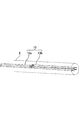
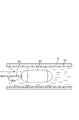
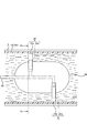
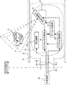
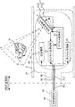
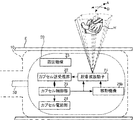
- FIG. 1 shows an example of observing a desired organ (heart H) in a subject P using the ultrasonic diagnostic apparatus 1 according to the present embodiment.
- the sheath 10 is inserted into the lumen of the subject P. 1 shows an example in which the sheath 10 passes through the throat T and is inserted to the end of the esophagus E (near the cardia of the stomach).
- the capsule-type main body 20 transmits ultrasonic waves to the heart H in a state of being fixedly arranged at a desired position (here, the esophagus E) in the sheath 10 and receives reflected waves from the heart H as echo signals. .
- transmission of ultrasonic waves and reception of reflected waves may be collectively referred to as “transmission and reception of ultrasonic waves”.
- the capsule body 20 transmits an echo signal to the external device 40 via the cable unit 30.
- the external device 40 processes the echo signal received from the capsule body 20 and creates and displays an ultrasonic image.
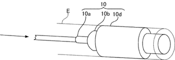
- the sheath 10 is a hollow member having a predetermined length and having an opening formed at one end.
- the sheath 10 is made of a material that can transmit ultrasonic waves (a material that does not reflect or attenuate ultrasonic waves).
- the sheath 10 is inserted into the lumen of the subject P orally by an operator or the like.
- the opening is outside the subject P, and liquid is injected into the sheath 10 through the opening (details will be described later).
- the predetermined length is determined by the observation target. For example, when observing the heart H, it is necessary to arrange the capsule-type main body 20 in the esophagus E. Therefore, since the sheath 10 needs to reach at least from the oral cavity of the subject P to the vicinity of the terminal end of the esophagus E (gastric cardia), the length of the sheath 10 is estimated from the body shape, age, etc. of the subject P. It is desirable to determine in advance.
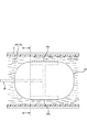
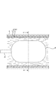
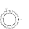
- the sheath 10 in the present embodiment is in a contracted state (for example, a rounded flat shape, which will be described later) when the liquid is not filled therein.
- a contracted state for example, a rounded flat shape, which will be described later
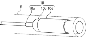
- FIGS. 2B and 2C are perspective views schematically showing the sheath 10 inserted into the lumen (esophagus E) of the subject P.
- FIG. The arrows in FIGS. 2B and 2C indicate that liquid is being injected into the sheath 10.
- the sheath 10 in the present embodiment includes a small diameter portion 10a and a large diameter portion 10b having a diameter larger than that of the small diameter portion 10a. At least the outer peripheral surface of the large-diameter portion 10b needs to be in contact with the inner wall surface of the lumen (esophagus E) of the subject P. Therefore, it is desirable that the diameter of the large-diameter portion 10b is determined in advance by estimating from the body shape, age, etc. of the subject P.
- the sheath 10 may be configured to have the same overall diameter. In this case, the sheath 10 may be formed so as to expand at least a portion where the capsule-type main body 20 is located.
- the sheath 10 has a rounded flat shape in which the hollow portion is crushed when the liquid is not filled therein (see FIG. 2A).
- the sheath 10 of the present embodiment is configured so that a crease is provided in the small-diameter portion 10a and the large-diameter portion 10b so as to be easily rounded and flat.
- the sheath 10 In a state where the sheath 10 is inserted into the esophagus E, when a liquid (for example, water) capable of transmitting ultrasonic waves is injected from the external device 40 (liquid adjusting unit 48, which will be described later), the sheath 10 gradually expands (FIG. 2B). reference). And in the state with which the liquid was filled inside, the outer peripheral surface of the large diameter part 10b of the sheath 10 contact
- a liquid for example, water
- the inserted sheath 10 may move due to the peristalsis of the esophagus E or the like. Therefore, for example, the movement of the sheath 10 can be prevented by fixing one end (opening side) of the sheath 10 to the mouthpiece M or the like disposed in the oral cavity of the subject P (see FIG. 1). . Further, it is desirable to provide a check valve or the like in a part of the sheath 10 so that the injected liquid does not flow out of the sheath 10.
- the shape of the sheath 10 contracted is not limited to a rounded flat shape, and it is sufficient that the sheath 10 can be easily inserted into the lumen of the subject P.
- a flat shape does not necessarily need to be rounded.
- the sheath 10 may be formed in the bellows structure which can be expanded-contracted in the major axis direction.
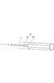
- FIGS. 3A to 3C are schematic views showing the capsule-type main body 20.
- FIG. 3C is a schematic diagram showing the capsule-type main body 20 inserted into the sheath 10.
- 3A to 3C show only a part of the cable portion 30.
- the capsule body 20 has a capsule shape that easily passes through the throat of the subject P.
- the outer periphery of the capsule-type main body 20 is made of a material that can transmit ultrasonic waves (a material that does not reflect or attenuate ultrasonic waves).
- a configuration (described later) for transmitting and receiving ultrasonic waves and the like is stored in the capsule body 20.
- one end of the cable portion 30 is connected to the rear end of the capsule-type main body portion 20.
- the other end of the cable unit 30 is connected to the external device 40.
- signal lines and the like for transmitting and receiving signals between the capsule-type main body portion 20 and the external device 40 are arranged.
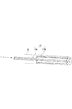
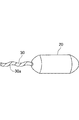
- the cable part 30 has flexibility (so-called string shape, see FIG. 3A). Therefore, in a state where the capsule body 20 is placed in the sheath 10 inserted into the lumen (esophagus E) of the subject P, the cable portion 30 is arranged along the shape in the sheath 10 (FIG. 1). reference).
- the cable portion 30 of the present embodiment is configured such that flexibility is reduced when twisting is applied.
- a groove 30 a is provided on the outer peripheral surface of the cable portion 30.
- the cable part 30 is bent along the groove 30 a to reduce flexibility (the cable part 30 has a so-called paper-cage shape, see FIG. 3B).
- the capsule-type main body 20 can be inserted into the sheath 10 filled with liquid by pushing the cable-shaped cable portion 30 into the sheath 10 (see FIG. 3C.
- the arrow indicates the capsule-type. The insertion direction of the main body 20 is shown).
- the capsule main body part 20 can be moved in the direction opposite to the insertion direction.
- the movement in the reverse direction may be performed in a state where the cable portion 30 is made flexible by twisting in the direction opposite to the direction in which the cable portion 30 turns.
- a string for moving the capsule body 20 can be provided separately from the cable part 30 while the cable part 30 is flexible.
- One end of the string is connected to the rear end of the capsule body 20.
- the string has a configuration in which flexibility decreases when twisting is applied.
- a groove is provided in the string.
- twisting is applied to the string, the flexibility of the string is lowered by being twisted along the groove.
- the capsule-type main body 20 can be inserted into the sheath 10 filled with the liquid by pushing the cord in the shape of the paper into the sheath 10.
- the capsule body 20 can be moved in the direction opposite to the insertion direction by pulling the string.
- the movement in the reverse direction may be performed in a state in which twisting is performed in a direction opposite to the direction in which the string is bent and the string is made flexible.
- the capsule body 20 can be moved within the sheath 10 by the operator pushing and pulling the cable 30 (or a string provided separately from the cable). Since the capsule-type main body 20 moves in the lumen of the subject P through the sheath 10, the capsule-type main body 20 does not contact the inner wall surface of the lumen of the subject P. Therefore, it is possible to prevent the inner wall surface from being damaged by the movement of the capsule-type main body 20.
- the method for inserting the capsule-type main body 20 into the sheath 10 and the method for moving the capsule-type main body 20 within the sheath 10 are not limited to the above examples.
- the capsule-type main body 20 is disposed in advance at one end (opening) of the sheath 10.
- the capsule-type main body 20 can be pushed into the large-diameter portion 10b of the sheath 10 by the pressure generated by the liquid injection. Thereafter, the position of the capsule-type main body portion 20 can be adjusted by pushing and pulling the cable portion 30.
- a self-propelled mechanism for example, a mechanism for propelling / retreating the liquid filled in the sheath 10 by rotating a screw provided at the rear end of the capsule-type main body 20
- a self-propelled mechanism for example, a mechanism for propelling / retreating the liquid filled in the sheath 10 by rotating a screw provided at the rear end of the capsule-type main body 20
- the self-propelled mechanism By providing the self-propelled mechanism, the operator does not need to push and pull the cable portion 30. Therefore, the insertion / movement of the capsule-type main body 20 with respect to the inside of the sheath 10 becomes easier.
- the capsule body 20 can be removed from the sheath 10 by pulling the cable portion 30.
- the external device 40 liquid adjusting unit 48, which will be described later
- the capsule main body 20 inside the sheath 10 can also be removed together. In this case, since it is not necessary to operate the cable part 30 directly, disconnection of the signal line etc. which are arrange
- the marker m may be provided in the cable part 30 (refer FIG. 1).
- the surgeon visually recognizes how much the cable portion 30 (capsule-type main body portion 20) is inserted into the lumen of the subject P (the position of the capsule-type main body portion 20 in the lumen of the subject P). Can be grasped.
- the marker m is provided on the cable portion 30 based on the general length from the oral cavity to the esophagus E.
- the marker m is provided so that the length of the cable portion 30 between the marker m and the capsule-type main body portion 20 is substantially equal to the general length from the oral cavity to the esophagus E.
- the surgeon checks the position of the marker m while pushing the cable part 30 and inserting the capsule-type main body part 20 into the sheath 10. When the marker m reaches the vicinity of the oral cavity, the surgeon can grasp that the capsule-type main body 20 is located in the esophagus E.
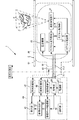
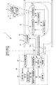
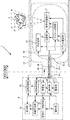
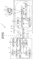
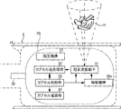
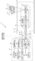
- FIG. 4 is a block diagram showing the configuration of the capsule-type main body 20 and the external device 40.
- the capsule body 20 includes an ultrasonic transducer 21, a capsule transceiver 22, a capsule controller 23, a capsule power supply 24, and a fixing mechanism 25.
- the ultrasonic transducer 21 is stored in the capsule main body 20.
- the ultrasonic transducer 21 transmits ultrasonic waves from the radiation surface based on the drive signal from the capsule control unit 23.
- the ultrasonic transducer 21 receives a reflected wave from the subject P and sends an echo signal based on the reflected wave to the capsule transceiver 22.
- a piezoelectric body or a MUT (Micromachining Ultrasound Transducer) element can be used as the vibration element constituting the ultrasonic transducer 21.
- the MUT element includes cMUT (Capacitive Micromachining Ultrasound Transducer) and pMUT (Piezoelectric Microsounding Transducer).
- a 2D array that transmits and receives ultrasonic waves by electronically scanning a plurality of vibration elements arranged in a two-dimensional array is shown as the ultrasonic transducer 21.
- the 2D array enables transmission and reception of ultrasonic waves in a quadrangular pyramid three-dimensional region (see FIG. 4).
- the capsule transmission / reception unit 22 transmits a control signal from the external device 40 (control unit 44, which will be described later) to the capsule control unit 23.
- the capsule control unit 23 transmits a drive signal to the ultrasonic transducer 21 based on the control signal.
- the capsule transceiver 22 receives an echo signal based on the reflected wave received by the ultrasonic transducer 21.
- the capsule transmission / reception unit 22 outputs an echo signal to the external device 40 (transmission / reception unit 41, which will be described later).
- transmission / reception of control signals and the like between the capsule main body 20 and the external device 40 is performed via the signal line SL ⁇ b> 1 disposed in the cable unit 30.
- the capsule controller 23 supplies a drive signal to the ultrasonic transducer 21 to perform a two-dimensional scan, and transmits an ultrasonic wave to the heart H.
- the capsule controller 23 includes, for example, a clock generator (not shown), a transmission delay circuit, and a pulsar circuit.
- the clock generator generates a clock signal that determines the transmission timing and transmission frequency of the ultrasonic signal.
- the transmission delay circuit applies a delay when transmitting the ultrasonic wave according to the focusing delay time for focusing the ultrasonic wave on the observation target and the deflection delay time for transmitting the ultrasonic wave to the observation target. carry out.
- the pulsar circuit has pulsars corresponding to the number of individual channels corresponding to the vibration elements.
- the pulsar circuit generates a driving pulse (driving signal) at a transmission timing subjected to a delay, and supplies the driving pulse (driving signal) to the vibration element constituting the ultrasonic transducer 21.
- the capsule transmission / reception unit 22 performs delay processing on the received echo signal, thereby converting the analog echo signal into digital data (reception data) subjected to phasing addition.
- the capsule transmission / reception unit 22 includes, for example, a gain circuit (not shown), an A / D converter, a reception delay circuit, and an adder.
- the gain circuit amplifies (applies gain) the echo signal output from the vibration element of the ultrasonic transducer 21 for each reception channel.
- the A / D converter converts the amplified echo signal into a digital signal.
- the reception delay circuit gives a delay time necessary for determining the reception directivity to the echo signal converted into the digital signal.
- the reception delay circuit uses a digital echo to calculate a convergence delay time for focusing the ultrasonic wave from the observation target and a deflection delay time for setting the reception directivity for the observation target. Give to the signal.
- the adder adds echo signals given delay times. By the addition, the reflection component from the direction corresponding to the reception directivity is emphasized. That is, the echo signal obtained from the observation target is phased and added by the reception delay circuit and the adder.
- the capsule transmission / reception unit 22 outputs an echo signal (received data) subjected to the delay process to the external device 40.
- the capsule power supply unit 24 receives power supply from an external device 40 (power supply unit 47, which will be described later).
- the capsule power supply unit 24 distributes the supplied power to the ultrasonic transducer 21, the capsule transmission / reception unit 22, and the capsule control unit 23.
- power supply from the external device 40 is performed via the signal line SL ⁇ b> 2 arranged in the cable unit 30.
- the fixing mechanism 25 is provided in the capsule-type main body 20, and fixedly arranges the capsule-type main body 20 at a desired position in the large-diameter portion 10b of the sheath 10.
- the capsule-type main body 20 can be placed in the lumen (esophagus E) of the subject P by fixing and arranging the capsule-type main body 20 at a desired position.
- the desired position is a position at which ultrasonic waves can be transmitted and received by the capsule body 20 with respect to the observation target. Whether or not the capsule body 20 is in a desired position is determined by, for example, an operator observing an ultrasound image obtained by transmitting and receiving ultrasound.
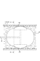
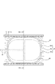
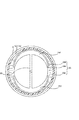
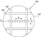
- FIGS. 5A to 5D are side views of the capsule-type main body 20 inserted into the large-diameter portion 10b of the sheath 10.
- FIG. 5B is a front view of the capsule body 20 in FIG. 5A as viewed from the I direction.
- FIG. 5D is a front view of the capsule body 20 in FIG. 5C as viewed from the II direction.
- descriptions of the components stored in the capsule-type main body 20 other than the fixing mechanism 25 and the cable part 30 are omitted.
- the capsule body 20 shown in FIGS. 5A to 5D includes a body 20a, a hemisphere 20b, and a shaft 20c.
- each component (other than the fixing mechanism 25) stored in the capsule-type main body 20 such as the ultrasonic vibrator 21 is disposed.
- the hemispherical portion 20b is a hollow member and is detachably disposed on the main body portion 20a.
- a fixing mechanism 25 is disposed inside the hemispherical portion 20b.
- the shaft portion 20 c is a member that protrudes from the main body portion 20 a into the hemispherical portion 20 b and connects the main body portion 20 a and the fixing mechanism 25.
- the fixing mechanism 25 in the present embodiment includes an inflating portion 25a.
- the expansion part 25a is provided in the capsule-type main body part 20 and expands when a fluid is supplied from the outside.
- the inflatable portion 25a is made of a stretchable member such as a resin material.
- the fluid injected into the expansion part 25a can be, for example, a liquid such as water or a gas such as air.
- the gas attenuates the ultrasonic waves. Therefore, when gas is used as the fluid, the fixing mechanism 25 (expansion portion 25a) is located outside the ultrasonic wave transmission / reception direction of the ultrasonic transducer 21 in a state where the capsule body 20 is fixed (expanded). It is desirable to be provided so that it may be located in. In this case, transmission and reception of ultrasonic waves by the ultrasonic vibrator 21 is not hindered by the fixing mechanism 25.
- a plurality of the expanding portions 25a are arranged at the front end and the rear end of the capsule-type main body portion 20.
- the expanding portions 25a are arranged at the front end and the rear end of the capsule-type main body portion 20.
- four inflatable portions 25 a in the present embodiment are provided at the front end and four at the rear end of the capsule-type main body portion 20.
- swelling part 25a is arrange
- the expansion part 25a and the main body part 20a are connected by a shaft part 20c.
- each of the plurality of inflating portions 25 a communicates with the fluid passage 60.
- the fluid passage 60 is a flow path that is provided in the cable portion 30 and communicates with the external device 40 (fluid adjusting portion 49, which will be described later).
- the fluid passage 60 passes through the main body portion 20 a and communicates with each of the inflating portions 25 a disposed at the tip of the capsule-type main body portion 20.
- the fluid passage 60 is inserted into the shaft portion 20c.
- each expansion part 25a When a fluid is supplied from the external device 40 to each expansion part 25a via the fluid passage 60, the expansion part 25a expands. As the expanding portion 25a expands, the hemispherical portion 20b is detached, and the expanding portion 25a protrudes outside the capsule-type main body portion 20. Each protruding end portion of the expanding portion 25a comes into contact with the inner wall of the large-diameter portion 10b of the sheath 10 (see FIGS. 5C and 5D). In the present embodiment, the four inflating portions 25a expand to expand in a cross shape, and the respective tip portions abut against the inner wall of the large diameter portion 10b of the sheath 10 (see FIG. 5D).
- the expanding portion 25a expands and comes into contact with the inner wall of the large-diameter portion 10b of the sheath 10, whereby the capsule-type main body portion 20 (main body portion 20a) is placed at a desired position in the large-diameter portion 10b of the sheath 10.
- FIG. 5C and FIG. 5D the description of the detached hemispherical portion 20b is omitted. It is also possible to provide the hemispherical portion 20b with a hole that can protrude to the outside of the capsule-type main body 20 when the expanding portion 25a expands. In this case, a configuration in which the hemispherical portion 20b is removed becomes unnecessary.
- the capsule-type main body 20 in the subject P by fixing and arranging the capsule-type main body 20 with respect to the large-diameter portion 10b of the sheath 10. And it becomes possible to observe with ultrasonic waves with respect to observation objects, such as the heart H, by the capsule-type main-body part 20 indwelled.
- the expansion unit 25a contracts to the original state (the state shown in FIGS. 5A and 5B) by sucking the fluid in the expansion unit 25a by the external device 40 (fluid adjustment unit 49, which will be described later).
- the fixing mechanism 25 in the present embodiment is not limited to this as long as the capsule-type main body 20 can be fixedly disposed by the expansion portion 25a directly contacting the inner wall of the large-diameter portion 10b of the sheath 10. .
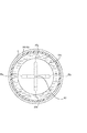
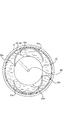
- FIGS. 6A to 6D another example of the fixing mechanism 25 according to the present embodiment will be described.
- 6A and 6C are side views of the capsule main body 20 inserted into the large-diameter portion 10b of the sheath 10.
- FIG. 6B is a cross-sectional view in the III-III direction in FIG. 6A.
- 6D is a cross-sectional view in the IV-IV direction in FIG. 6C.
- the description of the components stored in the capsule-type main body 20 other than the fixing mechanism 25 and the cable part 30 is omitted.
- a balloon member 25 b is provided on the outer peripheral surface of the capsule-type main body 20.
- Four balloon members 25b are provided at positions opposed in the radial direction of the capsule-type main body 20 (see FIGS. 6B and 6D. In FIGS. 6A and 6C, two of the four balloon members 25b are described. Is omitted).
- the balloon member 25b is made of a stretchable member such as a resin material.
- the balloon member 25b When a fluid is supplied from the external device 40 to each balloon member 25b via the fluid passage 60, the balloon member 25b expands.
- the inflated balloon member 25b comes into contact with the inner wall of the large-diameter portion 10b of the sheath 10 (see FIGS. 6C and 6D). Therefore, the balloon member 25b can fix and arrange the capsule-type main body 20 at a desired position in the large-diameter portion 10b of the sheath 10.
- the balloon member 25b in the present embodiment is an example of an “expanding portion”.
- the inflatable part only needs to be able to fix and arrange the capsule-type main body part 20 at a desired position in the large-diameter part 10b of the sheath 10. That is, the number, shape, position, and the like of the expanding portion are not limited to the above example.
- the sheath 10, the capsule body 20 and the fixing mechanism 25 according to the present embodiment are an example of “ultrasonic medical device”.
- the external device 40 includes a transmission / reception unit 41, a reception data processing unit 42, an image creation unit 43, a control unit 44, a display unit 45, an operation unit 46, a power supply unit 47, a liquid adjustment unit 48, a fluid And an adjustment unit 49.
- the transmission / reception unit 41 receives the echo signal from the capsule transmission / reception unit 22 and outputs it to the reception data processing unit 42. In addition, the transmission / reception unit 41 transmits a control signal from the control unit 44 to the capsule transmission / reception unit 22.
- the reception data processing unit 42 performs various types of signal processing on the echo signal output from the transmission / reception unit 41.
- the reception data processing unit 42 has a B mode processing unit.
- the B-mode processing unit receives the echo signal from the transmission / reception unit 41 and visualizes the amplitude information of the echo signal.
- the reception data processing unit 42 may have a CFM (Color Flow Mapping) processing unit.
- the CFM processing unit visualizes blood flow information.
- the reception data processing unit 42 may have a Doppler processing unit.
- the Doppler processing unit extracts the Doppler shift frequency component by phase detection of the echo signal, and generates a Doppler frequency distribution representing the blood flow velocity by performing FFT processing.
- the reception data processing unit 42 outputs the echo signal subjected to the signal processing to the image creation unit 43.
- the image creation unit 43 processes the echo signal after the signal processing output from the reception data processing unit 42 to create image data (ultrasound image data).
- the control unit 44 controls the operation of each component that the ultrasonic diagnostic apparatus 1 has. For example, the control unit 44 transmits a drive signal for driving the ultrasonic transducer 21 to the capsule transmission / reception unit 22 via the transmission / reception unit 41 to control transmission / reception of ultrasonic waves. Alternatively, the control unit 44 causes the display unit 45 to display an image (ultrasonic image) based on the image data (ultrasonic image data) created by the image creation unit 43.
- the display unit 45 includes a monitor such as a CRT or a liquid crystal display.
- the operation unit 46 includes an input device such as a keyboard and a mouse. The surgeon performs transmission / reception of ultrasonic waves by the capsule main body 20 via the operation unit 46.
- the liquid adjusting unit 48 is a device for injecting liquid into the sheath 10 and sucking the liquid filled in the sheath 10.
- the liquid may be stored in the liquid adjusting unit 48 itself, or may be supplied from the outside (for example, water supply).
- the fluid adjusting unit 49 is a device for supplying fluid or sucking the supplied fluid in order to make the fixing mechanism 25 (the expanding unit 25a or the like) function.
- the fluid may be stored in the fluid adjusting unit 49 itself, or may be supplied from the outside (for example, water supply).
- the operation of the liquid adjustment unit 48 and the fluid adjustment unit 49 can be either automatic control by the control of the control unit 44 or manual operation by an operator.
- each configuration of the external device 40 does not have to be mounted on one device as shown in FIG.
- the image creation unit 43 performs the creation of image data.
- the control unit 44 transmits the created image data to a display device in a remote place (for example, a large hospital where a specialist is located) via a communication line. Then, by observing an image based on the image data displayed on the display device by a specialist, it is possible to instruct an operator at a remote place to perform an appropriate treatment on the subject. Further, in this case, since there is no need to provide the display unit 45 in the external device 40, the size of the ultrasonic diagnostic apparatus 1 itself can be reduced.
- dedicated tanks may be provided as the liquid adjustment unit 48 and the fluid adjustment unit 49.
- the sheath 10, the capsule body 20, the fixing mechanism 25, the image creation unit 43, and the control unit 44 according to the present embodiment are examples of an “ultrasound diagnostic apparatus”.
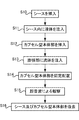
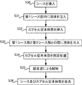
- the surgeon inserts the sheath 10 into the lumen of the subject P (S10).
- the inserted sheath 10 is fixed to the mouthpiece M in order to prevent movement due to peristalsis of the esophagus E or the like.
- the control unit 44 operates the liquid adjusting unit 48 to inject liquid into the sheath 10 (S11).
- the sheath 10 into which the liquid has been injected expands, and the outer peripheral surface of the large diameter portion 10b is in contact with the inner wall surface of the esophagus E.
- the surgeon inserts the capsule body 20 into the sheath 10 and pushes the cable 30 to insert the capsule body 20 to a desired position (S12).
- the control unit 44 operates the fluid adjusting unit 49 to inject a fluid into the inflating unit 25a (S13).
- the expanded portion 25a into which the fluid has been injected expands and comes into contact with the inner wall of the large-diameter portion 10b of the sheath 10, whereby the capsule-type main body portion 20 is fixedly disposed at a desired position in the large-diameter portion 10b of the sheath 10. (S14).
- the operator removes the sheath 10 and the capsule-type main body 20 from the subject P (S16). Specifically, first, the control unit 44 operates the fluid adjustment unit 49 to suck the fluid in the expansion unit 25a. When the fluid is sucked, the expanding portion 25a contracts. That is, the fixed arrangement of the capsule-type main body 20 is released. Therefore, the capsule main body 20 can be moved within the sheath 10. Next, the control unit 44 operates the liquid adjusting unit 48 to suck the liquid in the sheath 10. The sheath 10 contracts by sucking the liquid. That is, the state where the outer peripheral surface of the large-diameter portion 10b of the sheath 10 is in contact with the inner wall surface of the esophagus E is eliminated.
- the sheath 10 can be moved in the lumen of the subject P.
- the sheath 10 and the capsule body 20 are simultaneously removed from the subject P by pulling the opening portion of the sheath 10 and the cable portion 30 together with the capsule body 20 disposed in the sheath 10. Can do. If only the capsule-type main body 20 is to be removed, only the cable portion 30 may be pulled.
- the heart H is described as an example of the observation target, but the observation target is not limited to this.
- the configuration of the present embodiment can be applied to any part that can be observed by ultrasonic waves.
- the ultrasonic medical device includes a sheath 10, a capsule main body 20, and a fixing mechanism 25.
- the sheath 10 is inserted into the lumen of the subject P, and the outer peripheral surface (the outer peripheral surface of the large diameter portion 10b) is in contact with the inner wall surface of the subject P in a state in which the liquid is filled therein.
- the capsule-type main body 20 stores an ultrasonic transducer 21 that is inserted into the sheath 10 (inside the large-diameter portion 10b) and transmits / receives ultrasonic waves to / from the subject P (observation target in the subject P).
- the fixing mechanism 25 is provided in the capsule-type main body 20 and fixes and arranges the capsule-type main body 20 at a desired position in the sheath 10 (in the large-diameter portion 10b).
- the fixing mechanism 25 for fixing and arranging the capsule-type main body 20 at a desired position in the sheath 10 is provided. Therefore, according to the ultrasonic medical apparatus according to the present embodiment, the capsule main body 20 capable of transmitting and receiving ultrasonic waves can be placed on the observation target in the subject P. By placing the capsule body 20 in the lumen of the subject P, it is possible to continuously observe the observation target (for example, the heart H) using ultrasonic waves. Further, the capsule main body 20 can be easily inserted into the lumen of the subject P through the sheath 10.
- the fixing mechanism 25 is provided at a position outside the ultrasonic wave transmission / reception direction of the ultrasonic vibrator 21.
- the fixing mechanism 25 By arranging the fixing mechanism 25 outside the transmission / reception direction of the ultrasonic waves, the transmission / reception of ultrasonic waves is not hindered by the fixing mechanism 25. Therefore, the ultrasonic medical device can be observed with ultrasonic waves while being fixed by the fixing mechanism 25.
- the fixing mechanism 25 in the present embodiment has an inflating portion 25a.
- the expansion part 25a is provided in the capsule-type main body part 20, and expands when a fluid is supplied from the outside. Then, the inflated expanding portion 25a comes into contact with the inner wall of the sheath 10 (large diameter portion 10b), so that the capsule main body 20 can be fixedly arranged at a desired position in the sheath 10 (inside the large diameter portion 10b). it can.
- a plurality of inflatable portions 25 a are arranged at the front and rear ends of the capsule-type main body 20, and the front ends of the plurality of inflatable portions 25 a abut against the inner wall of the sheath 10.
- the expanding portion 25a as the fixing mechanism 25, the function of the fixing mechanism 25 can be exhibited only when the capsule-type main body portion 20 is fixedly arranged. Further, by providing a plurality of inflatable portions, the capsule-type main body portion 20 can be more securely fixed and disposed at a desired position in the sheath 10.
- the ultrasonic medical device has a cable part 30.
- One end of the cable part 30 is connected to the capsule body 20 and has flexibility.
- a fluid is supplied from the signal line (signal line SL ⁇ b> 1 and signal line SL ⁇ b> 2) for transmitting and receiving signals between the capsule-type main body part 20 and the external device 40 and the expansion device 25 a from the external device 40.
- a fluid passage 60 is provided.
- the cable portion 30 it is possible to easily transmit and receive signals between the capsule-type main body portion 20 and the external device 40. Further, by providing the fluid passage 60 and the signal line in the one cable part 30, the wiring between the capsule-type main body part 20 and the external device 40 can be integrated, so that handling becomes easy.
- At least a part of the cable part 30 has a structure in which the flexibility is lowered by twisting.
- the cable part 30 can be made into a paper web. Therefore, the operator can easily move the capsule-type main body 20 within the sheath 10 by pushing and pulling the cable portion 30.
- the sheath 10 has a flat shape (for example, a rounded flat shape) in a state where the liquid is not filled therein.
- the sheath 10 can be easily inserted into the lumen of the subject P by making the sheath 10 flat.
- the ultrasonic diagnostic apparatus 1 includes a sheath 10, a capsule body 20, a fixing mechanism 25, an image creation unit 43, and a control unit 44.
- the sheath 10 is inserted into the lumen of the subject P, and the outer peripheral surface (the outer peripheral surface of the large diameter portion 10b) is in contact with the inner wall surface of the subject P in a state in which the liquid is filled therein.
- the capsule-type main body 20 stores an ultrasonic transducer 21 that is inserted into the sheath 10 (inside the large-diameter portion 10b) and transmits / receives ultrasonic waves to / from the subject P (observation target in the subject P).
- the fixing mechanism 25 is provided in the capsule-type main body 20 and fixes and arranges the capsule-type main body 20 at a desired position in the sheath 10 (in the large-diameter portion 10b).
- the image creating unit 43 processes a signal based on the reflected wave received by the ultrasonic transducer 21 and creates image data.
- the control unit 44 causes the display unit 45 to display an image based on the image data created by the image creation unit 43.
- the fixing mechanism 25 for fixing and arranging the capsule-type main body 20 at a desired position in the sheath 10 (in the large-diameter portion 10b) is provided. Therefore, according to the ultrasonic diagnostic apparatus 1 according to the present embodiment, the capsule main body 20 capable of transmitting and receiving ultrasonic waves can be placed on the observation target of the lumen of the subject P.
- the ultrasound diagnostic apparatus 1 can create and display an ultrasound image based on the echo signal obtained by the capsule-type main body 20. Therefore, an operator or the like can observe the observation target in the subject P, and confirm and diagnose the state of the subject P.
- the ultrasonic diagnostic apparatus (ultrasonic medical apparatus) according to this embodiment is assumed to be used in the following situations.
- the ultrasonic diagnostic apparatus can be used when continuously monitoring the state of the heart H of the subject P accommodated in the emergency medical department.
- the subject P who develops acute heart disease and is accommodated in the emergency medical department is unconscious or cannot eat until after treatment. Therefore, even if the capsule-type main body 20 is placed in the esophagus E, there is little influence such as unpleasantness on the subject P.
- the ultrasonic diagnostic apparatus can be used in a situation where there is no specialist, for example, in an emergency site outside a hospital.
- a specialist for example, in an emergency site outside a hospital.
- image data obtained by the ultrasonic diagnostic apparatus By sending the image data obtained by the ultrasonic diagnostic apparatus to a large hospital where a specialist is located, it is possible to ask for an appropriate treatment instruction even in a remote place.
- image data by transmitting image data in advance from the emergency site to the transport destination hospital, it is possible to lead to quick treatment after arrival at the hospital.
- an ultrasonic diagnostic apparatus can be miniaturized, an ultrasonic diagnosis of the heart or the like can be easily performed even in an area (such as a remote area) where it is difficult to carry in a dedicated large apparatus. .
- an ultrasonic diagnostic apparatus 1 Next, an ultrasonic diagnostic apparatus 1 according to the second embodiment will be described with reference to FIGS. 8A to 10.
- the capsule body 20 is fixedly disposed at a desired position in the sheath 10 by the locking portion 25c and the expanding portion 25d.
- Detailed description of the same configuration as in the first embodiment may be omitted.
- FIGS. 8A to 8D are side views of the capsule main body 20 inserted into the large-diameter portion 10b of the sheath 10.
- FIG. 8B is a VV cross section in FIG. 8A.
- FIG. 8D is a VI-VI cross section in FIG. 8C.
- the description of the components stored in the capsule-type main body 20 other than the fixing mechanism 25 and the cable part 30 is omitted.
- the fixing mechanism 25 in the present embodiment includes a locking portion 25c and an inflating portion 25d.
- the locking portion 25c is disposed on the outer periphery of the capsule-type main body 20 and is movable in the radial direction of the capsule-type main body 20.
- FIG. 8A and the like an example in which two locking portions 25c are provided along the outer periphery of the capsule-type main body portion 20 is shown.
- the locking portion 25c is movable in the radial direction of the capsule-type main body 20 around a shaft portion 25e (see FIG. 8B and the like, which is omitted in FIGS. 8A and 8C). Note that the movement in the radial direction means that the vector of movement has a radial component.
- the locking portion 25c is made of a member having elasticity such as a resin material or a member having low elasticity such as a metal material.
- locking part 25c is comprised with the member which reflects and attenuates ultrasonic waves, such as a metal material, it is desirable that the latching
- the expansion part 25d is arranged between the locking part 25c and the capsule-type main body part 20, and expands when a fluid is supplied from the outside.
- the expanding portion 25d is disposed between the outer peripheral surface of the capsule-type main body portion 20 and the locking portion 25c.
- the inflating portion 25d is contracted, and thus the description thereof is omitted.
- the expansion part 25d communicates with the fluid passage 60.
- the expansion part 25d expands.
- the locking portion 25c moves in the radial direction. The moved locking portion 25c comes into contact with the inner wall of the large-diameter portion 10b of the sheath 10 (see FIGS. 8C and 8D).
- the inflating portion 25d is inflated, and the locking portion 25c is brought into contact with the inner wall of the large-diameter portion 10b of the sheath 10, so that the desired position in the large-diameter portion 10b of the sheath 10 is obtained.
- the capsule main body 20 can be fixedly arranged.
- the fixing mechanism 25 in the present embodiment has a configuration in which the capsule main body 20 can be fixedly disposed on the inner wall of the large-diameter portion 10b of the sheath 10 via the locking portion when the expansion portion expands. Not limited to.
- FIG. 9A and 9C are side views of the capsule-type main body portion 20 inserted into the large-diameter portion 10b of the sheath 10.
- FIG. 9B is a cross-sectional view in the VII-VII direction in FIG. 9A.
- 9D is a cross-sectional view taken along the line VIII-VIII in FIG. 9C.
- 9A to 9D the description of the components stored in the capsule-type main body 20 other than the fixing mechanism 25 and the cable part 30 is omitted.
- the capsule-type main body 20 shown in FIGS. 9A to 9D includes a main body 20a and an outer shell 20d.
- each component (other than the fixing mechanism 25) stored in the capsule-type main body 20 such as the ultrasonic vibrator 21 is disposed.
- the outer shell portion 20d is a hemispherical member that covers the main body portion 20a, and is arranged to be movable in the radial direction of the main body portion 20a.
- two outer shell portions 20d are provided so as to cover the main body portion 20a (see FIG. 9A and the like).
- the expansion part 25f is arranged between the main body part 20a and the outer shell part 20d.
- the expansion portion 25f expands when a fluid is supplied from the fluid passage 60.
- the inflating portion 25f is disposed between the outer peripheral surface of the capsule-type main body portion 20 and the outer shell portion 20d.
- the description is abbreviate
- the outer shell portion 20d moves in the radial direction by the expansion of the expansion portion 25f.
- the outer shell portion 20d that has moved contacts the inner wall of the large-diameter portion 10b of the sheath 10 (see FIGS. 9C and 9D). Therefore, the outer shell portion 20 d can fix and arrange the main body portion 20 a (capsule type main body portion 20) at a desired position in the large-diameter portion 10 b of the sheath 10.
- the outer shell portion 20d in the present embodiment is an example of a “locking portion”. Further, the outer shell portion 20d and the inflating portion 25f constitute a fixing mechanism 25. In this way, by using a part of the capsule-type main body 20 itself as a locking portion, the capsule-type main body 20 can be downsized.
- swelling part should just be able to fix-arrange the capsule-type main-body part 20 in the desired position in the large diameter part 10b of the sheath 10.
- a groove portion into which the locking portion 25c fits when the expansion portion 25d is contracted can be provided on the outer peripheral surface of the capsule-type main body portion 20. is there. With such a configuration, the outer diameter of the capsule main body 20 including the fixing mechanism 25 can be reduced. That is, the capsule-type main body 20 can be downsized.
- the operator inserts the sheath 10 into the lumen of the subject P (S20).
- the control unit 44 operates the liquid adjusting unit 48 to inject liquid into the sheath 10 (S21).
- the sheath 10 into which the liquid has been injected expands, and the outer peripheral surface of the large diameter portion 10b is in contact with the inner wall surface of the esophagus E.
- the operator inserts the capsule body 20 into the sheath 10 and pushes the cable 30 to insert the capsule body 20 to a desired position (S22).
- the control unit 44 operates the fluid adjustment unit 49 to inject a fluid into the expansion unit 25f (S23).
- the expanding portion 25d into which the fluid has been injected expands and moves the locking portion 25c in the radial direction of the capsule-type main body 20 (S24).
- the capsule body 20 When the locking portion 25c comes into contact with the inner wall of the large-diameter portion 10b of the sheath 10, the capsule body 20 is fixedly arranged at a desired position in the large-diameter portion 10b of the sheath 10 (S25).
- the operator removes the sheath 10 and the capsule-type main body 20 from the subject P (S27). Specifically, first, the control unit 44 operates the fluid adjustment unit 49 to suck the fluid in the expansion unit 25d. As the fluid is sucked, the expansion portion 25d contracts. As the expanding portion 25d contracts, the locking portion 25c is separated from the inner wall of the large-diameter portion 10b of the sheath 10. That is, the fixed arrangement of the capsule-type main body 20 is released. Next, the control unit 44 operates the liquid adjusting unit 48 to suck the liquid in the sheath 10. The sheath 10 contracts by sucking the liquid.
- the sheath 10 can be moved in the lumen of the subject P.
- the sheath 10 and the capsule body 20 are simultaneously removed from the subject P by pulling the opening portion of the sheath 10 and the cable portion 30 together with the capsule body 20 disposed in the sheath 10. Can do.
- the fixing mechanism 25 includes a locking portion 25c and an inflating portion 25d.
- the locking portion 25 c is disposed on the outer periphery of the capsule main body 20 and is movable in the radial direction of the capsule main body 20.
- the expansion part 25d is arranged between the locking part 25c and the capsule-type main body part 20, and expands when a fluid is supplied from the outside. Then, the expanded inflated portion 25d moves the locking portion 25c, and the locking portion 25c comes into contact with the inner wall of the large-diameter portion 10b of the sheath 10, whereby the capsule is placed at a desired position in the large-diameter portion 10b of the sheath 10.
- the mold body 20 can be fixedly arranged.
- the capsule-type main body portion 20 capable of transmitting and receiving ultrasonic waves can be provided to the observation target in the subject P as in the first embodiment. Can be placed.
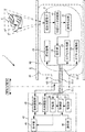
- FIG. 11 is a block diagram illustrating the configuration of the capsule main body 20 and the external device 40 according to the present embodiment.
- the fixing mechanism 25 is disposed on the sheath 10 side.
- the liquid adjustment unit 48 in the external device 40 has a function of injecting and sucking liquid into the sheath 10 (in the first sheath portion 11, which will be described later) and a function of injecting and sucking liquid into the fixing mechanism 25. Yes.
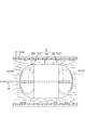
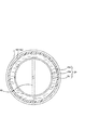
- FIGS. 12A to 12D are side views of the capsule main body 20 inserted into the large-diameter portion 10b of the sheath 10.
- FIG. 12B is a cross-sectional view in the IX-IX direction in FIG. 12A.
- 12D is a cross-sectional view in the XX direction in FIG. 12C.
- description of each component stored in the capsule main body 20 is omitted.
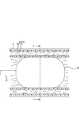
- the sheath 10 (at least the large-diameter portion 10b) in the present embodiment includes the first sheath portion 11 and the second sheath portion 12.
- the first sheath part 11 and the second sheath part 12 are hollow members having a predetermined length and having an opening formed at one end. Both the first sheath portion 11 and the second sheath portion 12 are made of a material that can transmit ultrasonic waves.
- the second sheath portion 12 is provided so as to cover the first sheath portion 11. That is, the sheath 10 in this embodiment has a double structure. Therefore, liquid can be injected between the first sheath portion 11 and the second sheath portion 12 (a gap between the outer peripheral surface of the first sheath portion 11 and the inner peripheral surface of the second sheath portion 12).
- the first sheath portion 11 is filled with liquid, the first sheath portion 11 and the second sheath portion 12 expand, and the outer peripheral surface of the second sheath portion 12 is the inner wall surface of the inner wall of the subject P (esophageal tract E). (See FIGS. 12A and 12B).
- the capsule-type main body portion 20 is inserted into the first sheath portion 11.
- the liquid adjusting portion 48 is connected to the first sheath portion 11 and the second sheath. Liquid is injected between the unit 12 and the unit 12.
- the second sheath portion 12 is in contact with the inner wall surface of the esophagus E, the first sheath portion 11 expands inward.
- the expanded inner wall of the first sheath portion 11 comes into contact with the outer wall of the capsule-type main body portion 20 inserted into the first sheath portion 11 (see FIGS. 12C and 12D). Therefore, the capsule-type main body 20 is fixedly disposed at a desired position in the first sheath portion 11 (in the large-diameter portion 10b of the sheath 10).
- the first sheath part 11 is an example of an “expanding part”. Further, the first sheath part 11 and the second sheath part 12 constitute a fixing mechanism 25.
- the first sheath part 11 is preferably formed of a material that is more stretchable than the second sheath part 12. By comprising in this way, when a liquid is inject
- the first sheath portion 11 only needs to be able to fix and arrange the capsule-type main body portion 20 at a desired position in the first sheath portion 11. That is, the shape of the first sheath portion 11 is not limited to the above example. For example, at least a part of the inner peripheral surface of the first sheath portion 11 can be formed into an uneven shape. In this case, since the capsule-type main body 20 is reliably fixed by the unevenness, the capsule-type main body 20 can be more securely fixed and arranged in the first sheath portion 11.
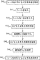
- the surgeon inserts the sheath 10 having the first sheath portion 11 and the second sheath portion 12 into the lumen of the subject P (S30).
- the control unit 44 operates the liquid adjusting unit 48 to inject the liquid into the first sheath portion 11 (S31).
- the first sheath portion 11 into which the liquid is injected is expanded, the second sheath portion 12 provided on the outer periphery thereof is also expanded.
- the outer peripheral surface of the second sheath portion 12 (the outer peripheral surface of the large diameter portion 10b of the second sheath portion 12) is in contact with the inner wall surface of the esophagus E.
- the surgeon inserts the capsule body 20 into the first sheath 11 and pushes the cable 30 to insert the capsule body 20 to a desired position (S32).
- the control unit 44 operates the liquid adjustment unit 48 to inject liquid between the first sheath portion 11 and the second sheath portion 12 (S33).
- the first sheath portion 11 expands inward by the liquid injection.
- the inner wall of the first sheath portion 11 (the large diameter portion 10b of the first sheath portion 11) abuts on the outer wall of the capsule main body portion 20, so that the capsule main body portion 20 is desired within the large diameter portion 10b of the sheath 10. (S34).
- the operator removes the sheath 10 and the capsule-type main body 20 from the subject P (S36). Specifically, first, the control unit 44 operates the liquid adjusting unit 48 to suck the liquid between the first sheath portion 11 and the second sheath portion 12. As the liquid is sucked, the first sheath portion 11 contracts. That is, the fixed arrangement of the capsule-type main body 20 is released. Next, the control unit 44 operates the liquid adjustment unit 48 to suck the liquid in the first sheath portion 11. By sucking the liquid, the entire sheath 10 contracts. That is, the state in which the outer peripheral surface of the large diameter portion 10b of the second sheath portion 12 is in contact with the inner wall surface of the esophagus E is eliminated.
- the sheath 10 can be moved in the lumen of the subject P.
- the sheath 10 and the capsule body 20 are simultaneously removed from the subject P by pulling the opening portion of the sheath 10 and the cable portion 30 together with the capsule body 20 disposed in the sheath 10. Can do.
- the fixing mechanism 25 may be provided in both the sheath 10 and the capsule-type main body 20. In this case, it is possible to more reliably perform the fixed arrangement of the capsule-type main body 20 at a desired position in the sheath 10.
- the fixing mechanism 25 has an inflating part (first sheath part 11).
- the 1st sheath part 11 is provided in the sheath 10, and expand
- the capsule main body 20 capable of transmitting and receiving ultrasonic waves can be provided to the observation target in the subject P as in the first and second embodiments. It becomes possible to detain. Further, since it is not necessary to provide the fixing mechanism 25 in the capsule body 20, the capsule body 20 can be reduced in size and simplified.
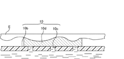
- the inner wall surface of the actual esophagus E has irregularities. Therefore, even when liquid is injected into the sheath 10 and expanded, the outer peripheral surface of the sheath 10 and the inner wall surface of the esophagus E may not be in sufficient contact. Therefore, it is desirable that the sheath 10 has a configuration that improves the adhesion between the outer peripheral surface thereof and the inner wall surface of the subject P.
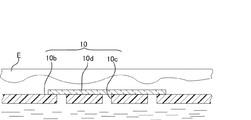
- FIGS. 14A to 14D The configuration of the sheath 10 according to this modification will be described with reference to FIGS. 14A to 14D.
- 14A and 14C are perspective views schematically showing the sheath 10 according to this modification.
- 14B and 14D are schematic views in which a part of the outer peripheral surface of the sheath 10 is enlarged.
- the sheath 10 has a fine hole 10c and an absorbing member 10d.
- the fine hole 10c is formed in at least a part of the outer peripheral surface of the sheath 10 (see FIG. 14B and the like).
- FIG. 14B and the like show a configuration in which a plurality of micro holes 10c are provided, at least one micro hole 10c is sufficient.
- the absorbing member 10d is a member provided at a position covering the fine hole 10c.
- the absorbing member 10d is normally a thin sheet, and is formed of a material that expands by absorbing liquid and can transmit ultrasonic waves (a material that does not reflect and attenuate ultrasonic waves).
- the absorbing member 10d covering the fine hole 10c expands by absorbing the liquid that has oozed out of the fine hole 10c, and abuts along the shape of the inner wall surface of the esophagus E (see FIGS. 14C and 14D). Since the absorbing member 10d becomes more elastic than the sheath 10 by absorbing the liquid, the adhesion with the inner wall surface of the esophagus E is improved.
- the outer peripheral surface of the sheath 10 (absorbing member 10d) can be used even when the inner wall surface of the lumen of the subject P is uneven. And the inner wall surface of the lumen of the subject P can be reliably brought into contact with each other.
- Modification 2 In the observation by the ultrasonic diagnostic apparatus 1, a large amount of echo signals are acquired. That is, a large amount of received data is transmitted to the external device 40.
- a configuration in which a large amount of received data based on an echo signal acquired by the capsule main body 20 is efficiently transmitted to the external device 40 will be described.
- a transmission unit 26 is provided in the capsule-type main body unit 20.
- a receiving unit 50 is provided in the external device 40.
- the transmission unit 26 compresses the data amount by performing compression processing on the echo signal received by the ultrasonic transducer 21. Further, the transmission unit 26 transmits the compressed reception data to the reception unit 50 provided in the external device 40 through the dedicated signal line SL3. The receiving unit 50 decompresses the compressed received data and outputs it to the received data processing unit 42.
- Data compression and decompression can use known methods.
- a control signal or the like from the control unit 44 is directly transmitted to the capsule control unit 23 via the signal line SL1.
- the transmission unit 26 compresses the echo signal and transmits it as received data to the external device 40 via the dedicated signal line SL3. That is, according to the ultrasonic diagnostic apparatus of the present modification, the amount of data transmitted from the capsule main body 20 to the external apparatus 40 is reduced, so that high-speed data transmission is possible.
- the configuration shown in FIG. 16 may be employed.
- the configuration shown in FIG. 16 is a configuration in which the reception data processing unit 42 and the image creation unit 43 provided in the external device 40 of the above embodiment are provided in the capsule body 20.
- signal lines from the capsule control unit 23 and the capsule power supply unit 24 for each component in the capsule main body 20 are omitted.
- the reception data processing unit 42 in this modification directly performs signal processing on the echo signal based on the reflected wave received by the ultrasonic transducer 21.
- the image creation unit 43 creates image data based on the signal-processed echo signal and sends it to the transmission unit 26.
- the transmission unit 26 transmits image data to the reception unit 50 of the external device 40 through the dedicated signal line SL3.
- the control unit 44 causes the display unit 45 to display an image based on the image data received by the receiving unit 50.
- the transmission unit 26 may perform compression processing on the image data. In this case, the receiving unit 50 decompresses the compressed image data.
- the capsule main body 20 creates image data therein and transmits the image data to the external device 40 via the dedicated signal line SL3. That is, according to the ultrasonic diagnostic apparatus 1 of this modification, high-speed data transmission is possible. Further, by forming the reception data processing unit 42, the image creation unit 43, and the transmission unit 26 with one semiconductor chip, real-time image data transmission is possible.
- the capsule body 20 when observing the heart H, the capsule body 20 may be disposed at a position where the esophagus E has the maximum diameter.
- the heart H is positioned obliquely with respect to the position where the esophagus E has the maximum diameter. That is, when the capsule main body 20 is disposed at a position where the esophagus E has the maximum diameter, the capsule main body 20 is positioned obliquely with respect to the heart H. Therefore, the capsule main body 20 needs to have a configuration capable of transmitting and receiving ultrasonic waves in an oblique direction.
- an angle changing mechanism 27 is provided in the capsule-type main body 20.
- the angle changing mechanism 27 is disposed on the back surface of the ultrasonic transducer 21 and holds the ultrasonic transducer 21 in a state where the ultrasonic transducer 21 is inclined at a predetermined angle.
- the predetermined angle may be determined in advance by estimating a spatial position between a planned position (for example, a position where the esophagus E has the maximum diameter) and the observation target (for example, the heart H) where the capsule body 20 is placed. it can. While being held by the angle changing mechanism 27, the ultrasonic transducer 21 can transmit and receive ultrasonic waves in an oblique direction.
- the position where the esophagus E reaches the maximum diameter and the spatial position of the heart H may differ depending on the body shape and age of the subject P. In some cases, it is desired to observe the heart H at a position other than the position where the esophagus E has the maximum diameter. Further, there may be a case where it is desired to finely adjust the transmission / reception direction of the ultrasonic wave in a state where the capsule main body 20 is fixedly arranged in the sheath 10 by the fixing mechanism 25.
- the angle changing mechanism 27 can be configured to be movable.
- the angle changing mechanism 27 shown in FIG. 18 includes a counter plate 27a and an adjusting mechanism 27b.
- the counter plate 27 a is a plate-like member provided on the back surface of the ultrasonic transducer 21.
- the adjustment mechanism 27b is a mechanism that is provided on the back surface of the counter plate 27a and changes the inclination of the ultrasonic transducer 21 via the counter plate 27a.
- the adjustment mechanism 27b is formed in an expandable / contractable shape (for example, a bellows shape).
- the fluid adjustment unit 49 in the external device 40 is configured to inject and suck fluid into the fixing mechanism 25 and the adjustment mechanism 27b.
- signal lines from the capsule power supply unit 24 for the respective components in the capsule main body 20 are omitted.
- the fluid adjusting unit 49 expands and contracts by injecting and sucking fluid to the adjusting mechanism 27b.
- the inclination of the ultrasonic transducer 21 is changed through the counter plate 27a. That is, the transmission / reception direction of the ultrasonic wave can be changed by extending / contracting the adjusting mechanism 27b.
- the adjustment mechanism 27b shown in FIG. 18 is configured to change the inclination only in one axial direction (the direction of the broken line arrow in FIG. 18), but may be configured to change the inclination in a plurality of axial directions. Further, a motor may be used as the adjustment mechanism 27b.
- the capsule controller 23 drives the counter plate 27a by controlling the motor.
- a motor is used as the adjusting mechanism 27b, a dedicated passage for injecting and sucking fluid from the fluid adjusting unit 49 becomes unnecessary.
- Modification 4 For example, even when the capsule-type main body 20 is fixedly arranged at a desired position in the large-diameter portion 10b of the sheath 10, the capsule-type main body 20 can move due to the influence of peristalsis or breathing of the esophagus E. There is sex. In this case, a deviation occurs in the transmission / reception direction of the ultrasonic wave with respect to the heart H. Therefore, deviation also occurs in the ultrasonic image data created by the echo signal based on the received reflected wave. If there is a deviation in the transmission / reception direction of the ultrasonic waves, there is a possibility that inconvenience may occur when the heart H is desired to be observed.
- a deviation amount calculation unit 51 is provided in the external device 40, and a correction mechanism 28 is provided in the capsule body 20.
- the deviation amount calculation unit 51 compares the image data obtained at a certain timing with the image data obtained at another timing, and determines whether or not there is a deviation between the images. For example, when 3D image data is acquired using a 2D array, the shift amount calculation unit 51 calculates a shift in the three-dimensional direction (XYZ direction). When it is determined that there is a shift between the images, the shift amount calculation unit 51 transmits the shift amount information to the capsule control unit 23 via the transmission / reception unit 41.
- the correction mechanism 28 is a mechanism for moving the ultrasonic transducer 21 in a predetermined direction (for example, a three-dimensional direction).
- a predetermined direction for example, a three-dimensional direction.
- the correction of the deviation is not limited to the above method, and a known method can be used.
- the deviation amount calculation unit 51 compares the reference image data acquired in advance with image data acquired at a timing different from the reference image data, and calculates the deviation amount in the three-dimensional direction.
- the deviation amount calculation unit 51 transmits the calculated deviation amount to the image creation unit 43.
- the image creation unit 43 corrects the shift of the image data acquired at different timings by image processing based on the transmitted shift amount.
- the control unit 44 causes the display unit 45 to display an image based on the corrected image data. In this case, the correction mechanism 28 is not necessary.
- the reflected wave of the ultrasonic wave has an angle dependency due to the structure of the observation target (the valve of the heart H).
- the reflected wave is strong when the ultrasonic wave hits the object to be observed vertically, and the reflected wave becomes weak when it hits diagonally.
- image data in two directions with respect to the same observation target is created, or by combining these echo signals, more accurate image data There is a possibility to create.
- Each of the ultrasonic transducers 21 is tilted by the angle changing mechanism 27 so that the ultrasonic transmission direction overlaps the observation target (heart H). That is, each ultrasonic transducer 21 can receive reflected waves from different directions for the same observation target. Each ultrasonic transducer 21 is controlled so that transmission / reception of each ultrasonic wave does not overlap. Furthermore, it is also possible for two ultrasonic transducers 21 to receive the reflected ultrasonic wave transmitted by one ultrasonic transducer 21. With the echo signals based on these reflected waves, the image creation unit 43 can create image data in different directions for the same observation target. Alternatively, the image creation unit 43 can create more accurate image data by synthesizing these echo signals. In FIG. 20, wiring (signal lines and fluid passage 60) between the capsule main body 20 and the external device 40, and signal lines from the capsule power supply unit 24 for the respective components in the capsule main body 20 are omitted. Yes.
- a 1D array in which vibration elements are arranged in a line can be used as the ultrasonic vibrator 21, a 1D array in which vibration elements are arranged in a line.
- a moving mechanism is provided in the capsule-type main body 20 (moving mechanism 29a, see FIG. 21A, moving mechanism 29b, see FIG. 22A).
- the moving mechanism is a mechanism that moves the 1D array in an arbitrary direction. Even with the ultrasonic transducer 21 of the 1D array, the moving mechanism can transmit and receive ultrasonic waves two-dimensionally or three-dimensionally with respect to the observation target.
- 21A and 22A wiring (signal lines and fluid passage 60) between the capsule-type main body 20 and the external device 40, and signal lines from the capsule power supply unit 24 for each component in the capsule-type main body 20 are shown. Omitted.
- FIG. 21B shows an example of a specific configuration of the moving mechanism 29a.
- the moving mechanism 29 a includes a rotating part 290 and a fixed part 291.
- a 1D array (ultrasonic transducer 21) is disposed on the upper surface of the rotating unit 290.
- the fixing part 291 is fixed in the capsule-type main body part 20 and holds the rotating part 290 rotatably (the arrow in FIG. 21B indicates the rotating direction of the rotating part 290).
- the capsule control unit 23 controls the ultrasonic transducer 21 to transmit and receive ultrasonic waves by rotating and stopping the rotating unit 290 by a predetermined movement angle.
- the capsule control unit 23 continuously repeats this control up to a predetermined rotation range.
- the ultrasonic transducer 21 can transmit and receive ultrasonic waves in a triangular pyramid three-dimensional region (see FIG. 21A). Note that if the movement angle is reduced, ultrasonic waves can be transmitted and received with high definition in a triangular pyramid-shaped three-dimensional region.
- An echo signal based on the reflected wave received by the ultrasonic transducer 21 is transmitted to the capsule transmitting / receiving unit 22 via the fixed unit 291 by a slip ring (not shown) or the like.
- the capsule control unit 23 can arbitrarily control the rotation direction of the rotation unit 290.
- the capsule controller 23 can cause the ultrasonic transducer 21 to reciprocate by rotating 180 degrees in a certain direction and then rotating 180 degrees in the opposite direction.
- an echo signal based on the reflected wave obtained by the rotating unit 290 can be transmitted to the fixed unit 291 using a signal line.
- FIG. 22B shows an example of a specific configuration of the moving mechanism 29b.
- the moving mechanism 29 b includes a fixed part 291, a slide part 292, and a slide part 293.
- the slide part 292 is composed of a pair of members, and the ultrasonic transducer 21 is disposed thereon.
- the slide part 292 is a mechanism for moving the ultrasonic transducer 21 in a predetermined direction (the direction of arrow A in FIG. 22B).
- the slide part 293 includes a pair of members, and the slide part 292 is disposed.
- the slide part 293 is a mechanism that moves the ultrasonic transducer 21 in a direction (arrow B direction in FIG. 22B) orthogonal to a predetermined direction (A direction) via the slide part 292.
- the slide part 293 is fixed on the fixing part 291.
- a stepping motor can be used as the slide portion 292 and the slide portion 293, a stepping motor can be used.
- the capsule control unit 23 drives and stops the slide unit 292 and the slide unit 293 by a predetermined amount of movement, and controls the ultrasonic transducer 21 to transmit and receive ultrasonic waves.
- the capsule control unit 23 continuously repeats this control up to a predetermined movement range.
- the ultrasonic transducer 21 can perform transmission / reception of ultrasonic waves in a quadrangular pyramid-shaped three-dimensional region composed of a plurality of two-dimensional regions (see FIG. 22A). Note that if each movement amount is reduced, ultrasonic waves can be transmitted and received with high definition in a three-dimensional area having a quadrangular pyramid shape. In FIG.
- a region indicated by a solid line extending from the ultrasonic transducer 21 is a two-dimensional region (one two-dimensional region) in which ultrasonic waves are transmitted and received in a state where the ultrasonic transducer 21 is disposed at a certain position. Show.
- the capsule control unit 23 drives the slide unit 292 and the slide unit 293
- the ultrasonic transducer 21 can transmit and receive ultrasonic waves to and from the entire region indicated by the alternate long and short dash line in FIG. 22A.
- any one of the slide part 292 and the slide part 293 should just be provided.
- the moving range of the ultrasonic transducer 21 can be widened by forming the slide portion 292 and the slide portion 293 in an arc shape. By moving the ultrasonic transducer 21 over a wide range, the ultrasonic transmission / reception range can be widened.
- the slide part 292 and the slide part 293 are not restricted to a stepping motor.
- the slide unit 292 and the slide unit 293 can be configured as a mechanism that moves the ultrasonic transducer 21 by injecting and sucking fluid from the fluid adjusting unit 49.
- the overall configuration of the ultrasound diagnostic apparatus 1 is not limited to the above example.
- the control unit 44 of the external device 40 controls each component in the capsule main body 20 such as driving of the ultrasonic transducer 21 via the transmission / reception unit 41.
- the power supply unit 47 transmits power for driving each component in the capsule main body 20 via the signal line SL2.
- a battery or the like can be provided in the capsule main body 20 as a power source of the capsule main body 20.
- the signal line SL2 is not necessary. Therefore, the cable part 30 can be reduced in diameter.
- the ultrasonic diagnostic apparatus 1 shown in FIG. 24 includes a capsule fluid adjustment unit 29 in the capsule-type main body 20.
- the capsule fluid adjustment unit 29 injects and sucks fluid into the fixing mechanism 25 based on the control of the capsule control unit 23.
- the fluid is supplied from the periphery of the capsule-type main body 20, for example.
- the fluid sucked from the fixing mechanism 25 can be discharged around the capsule-type main body 20.
- the fluid passage 60 is also unnecessary, the cable portion 30 itself is unnecessary. Therefore, for example, even when the capsule-type main body 20 is placed with respect to the conscious subject P, the cable portion 30 does not extend from the oral cavity. Therefore, it is possible to reduce discomfort felt by the subject P when using the ultrasonic diagnostic apparatus 1.
- FIG. 25 is a flowchart showing the operation of the ultrasonic diagnostic apparatus 1 according to this modification. 25 will be described based on the configuration of the first embodiment.
- the capsule main body 20 is stored in advance in the sheath 10 (in the large diameter portion 10b) folded in a flat shape (S40).
- surgeon inserts the sheath 10 storing the capsule-type main body 20 into the lumen of the subject P (S41).
- the control unit 44 operates the liquid adjusting unit 48 to inject liquid into the sheath 10 (S42).
- the surgeon pushes the cable part 30 and moves the capsule-type main body part 20 to a desired position (S43).
- the control unit 44 operates the fluid adjustment unit 49 to inject a fluid into the expansion unit 25a (S44).
- the expanded portion 25a into which the fluid has been injected expands and comes into contact with the inner wall of the large-diameter portion 10b of the sheath 10, whereby the capsule-type main body portion 20 is fixedly disposed at a desired position in the large-diameter portion 10b of the sheath 10. (S45).
- the operator removes the sheath 10 and the capsule-type main body 20 from the subject P (S47).
- the capsule main body is fixedly arranged at a desired position in the sheath by the fixing mechanism provided on at least one of the capsule main body or the sheath. Can do. Accordingly, it is possible to place the capsule-type main body portion with respect to the observation target at a desired position in the subject.
Landscapes
- Health & Medical Sciences (AREA)
- Life Sciences & Earth Sciences (AREA)
- Engineering & Computer Science (AREA)
- Medical Informatics (AREA)
- Surgery (AREA)
- Pathology (AREA)
- Radiology & Medical Imaging (AREA)
- Biophysics (AREA)
- Biomedical Technology (AREA)
- Heart & Thoracic Surgery (AREA)
- Physics & Mathematics (AREA)
- Molecular Biology (AREA)
- Nuclear Medicine, Radiotherapy & Molecular Imaging (AREA)
- Animal Behavior & Ethology (AREA)
- General Health & Medical Sciences (AREA)
- Public Health (AREA)
- Veterinary Medicine (AREA)
- Cardiology (AREA)
- Computer Networks & Wireless Communication (AREA)
- Ultra Sonic Daignosis Equipment (AREA)
Priority Applications (2)
| Application Number | Priority Date | Filing Date | Title |
|---|---|---|---|
| CN201380021433.9A CN104271047B (zh) | 2012-10-04 | 2013-10-04 | 超声波医疗装置、超声波诊断装置 |
| US14/474,830 US10123771B2 (en) | 2012-10-04 | 2014-09-02 | Ultrasound medical apparatus and ultrasound diagnosis apparatus |
Applications Claiming Priority (2)
| Application Number | Priority Date | Filing Date | Title |
|---|---|---|---|
| JP2012222587A JP6006074B2 (ja) | 2012-10-04 | 2012-10-04 | 超音波医療装置、超音波診断装置 |
| JP2012-222587 | 2012-10-04 |
Related Child Applications (1)
| Application Number | Title | Priority Date | Filing Date |
|---|---|---|---|
| US14/474,830 Continuation US10123771B2 (en) | 2012-10-04 | 2014-09-02 | Ultrasound medical apparatus and ultrasound diagnosis apparatus |
Publications (1)
| Publication Number | Publication Date |
|---|---|
| WO2014054805A1 true WO2014054805A1 (ja) | 2014-04-10 |
Family
ID=50435123
Family Applications (1)
| Application Number | Title | Priority Date | Filing Date |
|---|---|---|---|
| PCT/JP2013/077174 Ceased WO2014054805A1 (ja) | 2012-10-04 | 2013-10-04 | 超音波医療装置、超音波診断装置 |
Country Status (4)
| Country | Link |
|---|---|
| US (1) | US10123771B2 (enExample) |
| JP (1) | JP6006074B2 (enExample) |
| CN (1) | CN104271047B (enExample) |
| WO (1) | WO2014054805A1 (enExample) |
Families Citing this family (2)
| Publication number | Priority date | Publication date | Assignee | Title |
|---|---|---|---|---|
| JP6129509B2 (ja) * | 2012-10-04 | 2017-05-17 | 東芝メディカルシステムズ株式会社 | 超音波医療装置及び超音波画像診断装置 |
| US20190015070A1 (en) | 2017-07-11 | 2019-01-17 | The Board Of Trustees Of The Leland Stanford Junior University | Ultrasonic Capsule Endoscopy Device having Image-based Relative Motion Estimation |
Citations (3)
| Publication number | Priority date | Publication date | Assignee | Title |
|---|---|---|---|---|
| JP2003135388A (ja) * | 2001-10-30 | 2003-05-13 | Olympus Optical Co Ltd | 内視鏡装置 |
| JP2004000440A (ja) * | 2001-11-12 | 2004-01-08 | Korea Inst Of Science & Technology | マイクロカプセル型ロボット及び内視鏡システム |
| JP2004222998A (ja) * | 2003-01-23 | 2004-08-12 | Olympus Corp | 超音波診断用カプセル |
Family Cites Families (11)
| Publication number | Priority date | Publication date | Assignee | Title |
|---|---|---|---|---|
| JP2585270B2 (ja) | 1987-05-21 | 1997-02-26 | オリンパス光学工業株式会社 | 超音波内視鏡用バル−ン |
| JP2008526419A (ja) * | 2005-01-18 | 2008-07-24 | コーニンクレッカ フィリップス エレクトロニクス エヌ ヴィ | 消化管内の流体を標本採取するための電子制御される摂取可能なカプセル |
| JP4800692B2 (ja) * | 2005-07-19 | 2011-10-26 | オリンパス株式会社 | カプセル型医療装置用留置装置 |
| US20070167825A1 (en) * | 2005-11-30 | 2007-07-19 | Warren Lee | Apparatus for catheter tips, including mechanically scanning ultrasound probe catheter tip |
| WO2008081601A1 (ja) * | 2007-01-05 | 2008-07-10 | Olympus Medical Systems Corp. | カプセル型医療装置 |
| JP2009028245A (ja) * | 2007-07-26 | 2009-02-12 | Hoya Corp | カプセル型医療機器 |
| CN102065775B (zh) * | 2008-02-20 | 2015-01-07 | 梅约医学教育与研究基金会 | 超声引导系统和方法 |
| CN201441450U (zh) * | 2008-09-24 | 2010-04-28 | 郁如煌 | 用于超声引导下穿刺治疗体内肿瘤的系列化冷冻探针 |
| WO2011153434A2 (en) * | 2010-06-03 | 2011-12-08 | The General Hospital Corporation | Apparatus and method for devices for imaging structures in or at one or more luminal organs |
| US8923949B2 (en) | 2010-06-23 | 2014-12-30 | Biosense Webster (Israel) Ltd. | Transesophageal echocardiography capsule |
| CN102525596B (zh) * | 2011-12-31 | 2014-09-17 | 重庆海扶医疗科技股份有限公司 | 超声采集和治疗控制系统及其获取图像的方法 |
-
2012
- 2012-10-04 JP JP2012222587A patent/JP6006074B2/ja active Active
-
2013
- 2013-10-04 CN CN201380021433.9A patent/CN104271047B/zh active Active
- 2013-10-04 WO PCT/JP2013/077174 patent/WO2014054805A1/ja not_active Ceased
-
2014
- 2014-09-02 US US14/474,830 patent/US10123771B2/en active Active
Patent Citations (3)
| Publication number | Priority date | Publication date | Assignee | Title |
|---|---|---|---|---|
| JP2003135388A (ja) * | 2001-10-30 | 2003-05-13 | Olympus Optical Co Ltd | 内視鏡装置 |
| JP2004000440A (ja) * | 2001-11-12 | 2004-01-08 | Korea Inst Of Science & Technology | マイクロカプセル型ロボット及び内視鏡システム |
| JP2004222998A (ja) * | 2003-01-23 | 2004-08-12 | Olympus Corp | 超音波診断用カプセル |
Also Published As
| Publication number | Publication date |
|---|---|
| CN104271047A (zh) | 2015-01-07 |
| US10123771B2 (en) | 2018-11-13 |
| CN104271047B (zh) | 2016-05-11 |
| JP2014073269A (ja) | 2014-04-24 |
| JP6006074B2 (ja) | 2016-10-12 |
| US20140371596A1 (en) | 2014-12-18 |
Similar Documents
| Publication | Publication Date | Title |
|---|---|---|
| CN104066383B (zh) | 超声波医疗装置以及超声波图像诊断装置 | |
| CN111698950B (zh) | 用于经食道超声心动图的无线操作 | |
| JP6961099B2 (ja) | 経食道心エコーのためのデバイス、システム及び方法 | |
| JP6899804B2 (ja) | 超音波診断装置および超音波診断装置の作動方法 | |
| JP3799612B2 (ja) | 超音波内視鏡装置 | |
| JP6006074B2 (ja) | 超音波医療装置、超音波診断装置 | |
| JP6099926B2 (ja) | 超音波医療装置及び超音波画像診断装置 | |
| JP2020156730A (ja) | 超音波観測装置及び超音波内視鏡システム | |
| JP6987029B2 (ja) | 超音波診断装置、及び、超音波診断装置の作動方法 | |
| US6716176B1 (en) | Device for use in temporary insertion of a sensor within a patient's body | |
| US20150025384A1 (en) | Ultrasound medical apparatus and ultrasound diagnosis apparatus | |
| JP2005176907A (ja) | 体腔内留置型検査装置 | |
| JP2005027724A (ja) | 超音波診断装置 | |
| JP7301114B2 (ja) | 超音波診断装置、及び、超音波診断装置の作動方法 | |
| JP7422616B2 (ja) | 医療器具および内視鏡 | |
| RU2795943C2 (ru) | Беспроводное управление для чреспищеводной эхокардиографии | |
| JP2006122133A (ja) | 超音波診断医用カプセル装置 | |
| WO2023053662A1 (ja) | 超音波内視鏡システムおよび超音波内視鏡システムの作動方法 | |
| JP3812676B2 (ja) | 超音波内視鏡装置 |
Legal Events
| Date | Code | Title | Description |
|---|---|---|---|
| WWE | Wipo information: entry into national phase |
Ref document number: 201380021433.9 Country of ref document: CN |
|
| 121 | Ep: the epo has been informed by wipo that ep was designated in this application |
Ref document number: 13844391 Country of ref document: EP Kind code of ref document: A1 |
|
| NENP | Non-entry into the national phase |
Ref country code: DE |
|
| 122 | Ep: pct application non-entry in european phase |
Ref document number: 13844391 Country of ref document: EP Kind code of ref document: A1 |