WO2014054647A1 - ドットパターン、ドットパターン形成媒体、ドットパターンの画像データを生成するプログラム、ドットパターン形成装置、光学装置、光学読み取り装置、情報入出力装置、ドットパターン読み取り装置 - Google Patents
ドットパターン、ドットパターン形成媒体、ドットパターンの画像データを生成するプログラム、ドットパターン形成装置、光学装置、光学読み取り装置、情報入出力装置、ドットパターン読み取り装置 Download PDFInfo
- Publication number
- WO2014054647A1 WO2014054647A1 PCT/JP2013/076722 JP2013076722W WO2014054647A1 WO 2014054647 A1 WO2014054647 A1 WO 2014054647A1 JP 2013076722 W JP2013076722 W JP 2013076722W WO 2014054647 A1 WO2014054647 A1 WO 2014054647A1
- Authority
- WO
- WIPO (PCT)
- Prior art keywords
- dot pattern
- dot
- dots
- information
- predetermined
- Prior art date
Links
Images


Classifications
-
- G—PHYSICS
- G06—COMPUTING OR CALCULATING; COUNTING
- G06K—GRAPHICAL DATA READING; PRESENTATION OF DATA; RECORD CARRIERS; HANDLING RECORD CARRIERS
- G06K19/00—Record carriers for use with machines and with at least a part designed to carry digital markings
- G06K19/06—Record carriers for use with machines and with at least a part designed to carry digital markings characterised by the kind of the digital marking, e.g. shape, nature, code
- G06K19/06009—Record carriers for use with machines and with at least a part designed to carry digital markings characterised by the kind of the digital marking, e.g. shape, nature, code with optically detectable marking
- G06K19/06037—Record carriers for use with machines and with at least a part designed to carry digital markings characterised by the kind of the digital marking, e.g. shape, nature, code with optically detectable marking multi-dimensional coding
-
- G—PHYSICS
- G06—COMPUTING OR CALCULATING; COUNTING
- G06F—ELECTRIC DIGITAL DATA PROCESSING
- G06F16/00—Information retrieval; Database structures therefor; File system structures therefor
- G06F16/90—Details of database functions independent of the retrieved data types
- G06F16/95—Retrieval from the web
- G06F16/955—Retrieval from the web using information identifiers, e.g. uniform resource locators [URL]
-
- G—PHYSICS
- G06—COMPUTING OR CALCULATING; COUNTING
- G06K—GRAPHICAL DATA READING; PRESENTATION OF DATA; RECORD CARRIERS; HANDLING RECORD CARRIERS
- G06K19/00—Record carriers for use with machines and with at least a part designed to carry digital markings
- G06K19/06—Record carriers for use with machines and with at least a part designed to carry digital markings characterised by the kind of the digital marking, e.g. shape, nature, code
- G06K19/06009—Record carriers for use with machines and with at least a part designed to carry digital markings characterised by the kind of the digital marking, e.g. shape, nature, code with optically detectable marking
- G06K19/06046—Constructional details
- G06K19/0614—Constructional details the marking being selective to wavelength, e.g. color barcode or barcodes only visible under UV or IR
-
- G—PHYSICS
- G06—COMPUTING OR CALCULATING; COUNTING
- G06K—GRAPHICAL DATA READING; PRESENTATION OF DATA; RECORD CARRIERS; HANDLING RECORD CARRIERS
- G06K7/00—Methods or arrangements for sensing record carriers, e.g. for reading patterns
- G06K7/10—Methods or arrangements for sensing record carriers, e.g. for reading patterns by electromagnetic radiation, e.g. optical sensing; by corpuscular radiation
- G06K7/14—Methods or arrangements for sensing record carriers, e.g. for reading patterns by electromagnetic radiation, e.g. optical sensing; by corpuscular radiation using light without selection of wavelength, e.g. sensing reflected white light
- G06K7/1404—Methods for optical code recognition
- G06K7/1408—Methods for optical code recognition the method being specifically adapted for the type of code
Definitions
- the present invention relates to encoding a code (numerical value or information) using a dot pattern composed of a plurality of dots.
- a technique for expressing a code (numerical value or information) by an array (dot pattern) of a plurality of fine dots printed on paper (or displayed by display means) is widely used.
- Grid 3 Onput registered trademark
- Patent Document 1 Japanese Patent No. 3706385
- Patent Document 2 Japanese Patent No. 377152
- FIG. 81 shows a code expression according to a direction in which information dots are shifted from a virtually set reference point according to the prior art. According to FIG. 81, since the information dots are arranged so as to be shifted in eight directions from the reference point, the number of codes obtained by multiplying the number of information dots by eight ways per information dot can be expressed. it can.
- FIG. 82 shows a code expression according to the direction and distance in which information dots are shifted from a virtually set reference point according to the prior art.
- the dots are arranged in eight different directions from the reference point, with two different distances, a distance close to the reference point and a distance far from the reference point, so that there are 16 dots per dot.
- the number of codes multiplied by the number of can be expressed.
- the object of the present invention is a technology that embodies the definition of information based on the distance and direction between two dots rather than the dot arrangement position.
- a dot pattern for solving this problem is a dot pattern having a plurality of information dots, and the dot pattern is at least one set of start point information dots and end point information dots.
- the plurality of information dots are arranged with a predetermined distance value or a predetermined distance value between predetermined directions between the adjacent information dots in a predetermined order from the starting point information dot,
- This is a dot pattern in which a code is encoded based on a predetermined distance value or a predetermined distance value between predetermined directions.
- FIG. 1st embodiment of the present invention It is a figure showing a 1st embodiment of the present invention. It is a figure showing a 1st embodiment of the present invention. It is a figure showing a 1st embodiment of the present invention. It is a figure showing a 1st embodiment of the present invention. It is a figure showing a 1st embodiment of the present invention. It is a figure showing a 1st embodiment of the present invention. It is a figure showing a 1st embodiment of the present invention. It is a figure showing a 1st embodiment of the present invention. It is a figure showing a 1st embodiment of the present invention. It is a figure showing a 1st embodiment of the present invention. It is a figure showing a 1st embodiment of the present invention. It is a figure showing a 1st embodiment of the present invention. It is a figure showing a 1st embodiment of the present invention. It is a figure showing a 1st embodiment of the present invention. It is a figure showing
- FIG. 1st embodiment of the present invention It is a figure showing a 1st embodiment of the present invention. It is a figure showing a 1st embodiment of the present invention. It is a figure showing a 1st embodiment of the present invention. It is a figure showing a 1st embodiment of the present invention. It is a figure showing a 1st embodiment of the present invention. It is a figure showing a 1st embodiment of the present invention. It is a figure showing a 1st embodiment of the present invention. It is a figure showing a 1st embodiment of the present invention. It is a figure showing a 1st embodiment of the present invention. It is a figure showing a 1st embodiment of the present invention. It is a figure showing a 1st embodiment of the present invention. It is a figure showing a 1st embodiment of the present invention. It is a figure showing a 1st embodiment of the present invention. It is a figure showing a 1st embodiment of the present invention. It is a figure showing
- FIG. 1st embodiment of the present invention It is a figure showing a 1st embodiment of the present invention. It is a figure showing a 1st embodiment of the present invention. It is a figure showing a 1st embodiment of the present invention. It is a figure showing a 1st embodiment of the present invention. It is a figure showing a 1st embodiment of the present invention. It is a figure showing a 1st embodiment of the present invention. It is a figure showing a 1st embodiment of the present invention. It is a figure showing a 1st embodiment of the present invention. It is a figure showing a 1st embodiment of the present invention. It is a figure showing a 1st embodiment of the present invention. It is a figure showing a 1st embodiment of the present invention. It is a figure showing a 1st embodiment of the present invention. It is a figure showing a 1st embodiment of the present invention. It is a figure showing a 1st embodiment of the present invention. It is a figure showing
- the present embodiment is a dot pattern that is composed of one row (or column), and a plurality of dots are arranged in that row (or column).
- This dot pattern is a kind of two-dimensional code, which is a code (numerical value or information) encoded using fine dots.
- the arrangement of information dots is determined so that information dots arranged adjacent to each other have a predetermined distance. Then, the permutation of the distance between information dots arranged adjacently, the permutation of long and short ranks, the combination of long and short ranks, the permutation of ratios, the combination of ratios, the absolute value, the permutation of absolute values, the combination of absolute values.
- the code is encoded by at least one of the following.
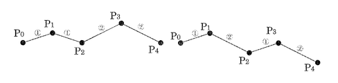
- FIG. 1, FIG. 2, FIG. 3, and FIG. 4 are dot patterns in which codes are encoded based on the distance between information dots or the distance between predetermined directions of information dots.
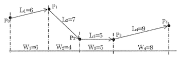
- FIG. 1 shows a dot pattern in which a code is encoded based on the value of the distance between information dots.
- the starting point information dot P0 that is the starting point for arranging the information dots in a predetermined order is arranged.
- information dots P1 are arranged with a predetermined distance.
- the information dot P2 is arranged at a position having a predetermined distance from the information dot P1.
- an information dot P3 is arranged, and an end point information dot P4 that is an end point for arranging the information dot is arranged to generate a dot pattern.
- the encoding of the code includes a distance L1 between information dots P0P1, a distance L2 between P1P2, a distance L3 between P2P3, and a distance L4 between P3P4, a permutation of long and short ranks, a combination of long and short ranks, a permutation of ratios, a ratio Or a combination of absolute values, a permutation of absolute values, or a combination of absolute values.
- the long and short order is to rank the distances L1 to L4 between information dots from No. (1) to No. (4).
- the distance in the rank from (1) to (3) If there are two identical distances between the information dots, the distance in the rank from (1) to (3), and if there are three identical distances, the distance in the rank from (1) to (2) If all the four distances are the same distance, the distance of the rank (1) only is assigned between the four information dots.
- any one of four different relative distances of (1) to (4) is assigned to the four information dots, but there are many different distances between the information dots.
- the rank may be determined by measuring the distance between information dots. Considering the printing accuracy, distortion of the printing medium, the accuracy of the optical reader, and the deformation of the captured image that occurs when the optical reader is tilted by hand, etc. It is preferable to set the distance value between the information dots so that the order is determined on the assumption that there is an increase or decrease in the distance. Therefore, the setting of the distance for which the order is changed by one requires an increase / decrease that can be reliably distinguished from an increase / decrease of the distance of about 5 to 10%. Accordingly, if the distance between the information dots is increased or decreased within about 5 to 10%, they should be in the same order. These ways of increasing / decreasing can also be applied when there are many different distance candidates between information dots. This increase / decrease increases as the number of assigned information dots increases. However, this is not the case when there is no deformation or the like that occurs during shooting with the optical reading device.
- the ratio is a ratio of distances L1 to L4 with respect to a predetermined reference distance.
- the predetermined reference distance may be a distance L0 between P0P4, and may be a ratio of distances L1 to L4 to the distance L0, or may be a ratio to a distance between any information dots (for example, distance L1).
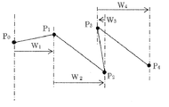
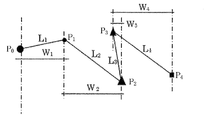
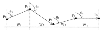
- FIG. 2 shows a dot pattern in which a code is encoded based on a distance value between predetermined directions.
- a straight line having a predetermined angle is drawn for each information dot, and a distance between the straight lines is obtained between a straight line drawn for a certain information dot and a straight line drawn in the same direction with respect to an adjacent information dot. This is the distance between the predetermined directions.
- a vertical line passing through each information dot is drawn.
- a distance W1 between a straight line passing through P0 and a straight line passing through P1 a distance W2 between a straight line passing through P1 and a straight line passing through P2, a distance W3 between a straight line passing through P2 and a straight line passing through P3, and a straight line passing through P3 and P4
- the distance W4 between the straight lines passing through A code is encoded by a permutation of long and short ranks of W1 to W4, a combination of long and short ranks, a permutation of ratios, a combination of ratios, or at least one of an absolute value, a permutation of absolute values, and a combination of absolute values.
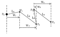
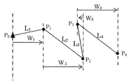
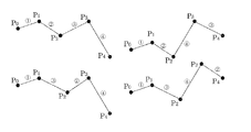
- FIG. 3 and 4 show an example in which information dots are arranged so that different information dots intersect with each other instead of the belt-shaped information dots shown in FIG. In this way, any arrangement may be used as long as information dots arranged in a predetermined order can be specified.
- FIG. 3 illustrates a case where a code is encoded based on distances L1 to L4 between information dots
- FIG. 4 illustrates a case where a code is encoded based on distances W1 to W4 in a predetermined direction. .
- the codes to be encoded differ depending on the order in which the information dots are arranged and the code encoding method.
- Such a dot pattern is printed on paper (or displayed by display means), and the code can be decoded by photographing the dot pattern with a camera device and analyzing the image data with a processor. Then, various processes corresponding to the decoded code, for example, output of contents such as sound, image, and moving image, execution of programs, operation instructions such as sound reproduction / recording, and the like are performed.
- information dots are extracted from image data, a distance value between adjacent information dots or a distance between predetermined directions is calculated, and a distance value between information dots is calculated.
- a code corresponding to a permutation of ranks, a combination of long and short ranks, a permutation of ratios, a combination of ratios, or an absolute value, a permutation of absolute values, a combination of absolute values is decoded.
- the error of the distance value between information dots is a predetermined percentage (5) in consideration of printing deviation, distortion of the printing medium, and tilt of the camera when reading the dot pattern. It is preferable to design the analysis program so as to determine the distance between the information dots on the assumption that it is about ⁇ 10%).
- the position of the read dot is the same as the predetermined position. It is preferable to design the analysis program so that it is recognized as being located at a predetermined position on the data as long as it is within a predetermined area at the center.
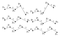
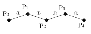
- FIG. 5 is a diagram in which the information dots in the next order are arranged at the position where the distance value between the information dots is the closest to the information dots.
- FIG. 6 shows information dots arranged in the next order in a predetermined direction from the information dots.
- P1 when P1 is arranged, P1 is arranged at a predetermined distance and direction (for example, 15 degrees) from P0.
- P2 is arranged at a predetermined distance and direction from P1.
- P3 and P4 are arranged.
- 7 and 8 are diagrams for explaining the case where the arrangement of information dots is determined by the distance and direction from a specific information dot.
- FIG. 7 shows an example in which information dots are arranged at a predetermined distance and direction from the start point information dot P0.
- the information dots P1 to P4 are arranged at a predetermined distance and direction from P0.
- FIG. 8 shows an example in which information dots are arranged at a predetermined distance and direction from the information dot P0.
- information dots are arranged in a predetermined distance and two directions from P0 in the order of P1, P2, P3, and P4.
- P2 and P4 are arranged as end point information dots.
- it may be arranged in three or more directions from P0, and the end point information dots may be arranged at the end points in the plurality of directions.
- 9 and 10 show information dots arranged in the following order at positions having a predetermined distance from the information dots and a predetermined rotation angle.
- FIG. 9 is a diagram in which the rotation angle is determined using a predetermined direction (reference line indicated by a one-dot chain line) as a reference for the rotation angle for all information dots as a vertical line passing through the information dot.
- a predetermined direction reference line indicated by a one-dot chain line
- the information dot P1 is arranged at a position having a predetermined distance L1 from P0 in the direction rotated clockwise by a predetermined angle ⁇ 1 around P0 from the vertical line passing through P0.
- the information dot P2 is arranged at a position having a predetermined distance L2 from P1 in a direction rotated by a predetermined angle ⁇ 2 clockwise from the vertical line passing P1 about P1.
- information dots P3 and P4 are arranged.
- the code is encoded by a combination of ratios, or at least one of an absolute value, a permutation of absolute values, and a combination of absolute values.
- FIG. 10 is a diagram in which a predetermined direction (a reference line indicated by a one-dot chain line) as a reference for the rotation angle is varied depending on the information dot.
- the information dot P1 is arranged at a position having a predetermined distance L1 from P0 in the direction rotated clockwise by a predetermined angle ⁇ 1 around P0 from the vertical line passing through P0.
- this is a direction rotated by a predetermined angle ⁇ 2 clockwise about P1 from that position and a predetermined distance L2 from P1.
- the information dot P2 is arranged at a position having
- the information dot P3 is arranged at a position having a predetermined distance L3 from P2 in the direction rotated clockwise by a predetermined angle ⁇ 3 about P2 from the vertical line passing through P2.
- the code may be encoded based on a combination of ⁇ 1, ⁇ 2, ⁇ 3, ⁇ 4 and distances W1, W2, W3, W4 in predetermined directions between information dots arranged adjacent to each rotation angle.
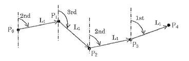
- the information dot next to the start point information dot is defined at a predetermined rotation angle with respect to a predetermined direction from the start point information dot, and the subsequent information dots are the previous information dot and the previous one. It is a figure explaining the case where it defines with the predetermined
- the information dot P1 is arranged at a position having a predetermined distance L1 from P0 in the direction rotated clockwise by a predetermined angle ⁇ 1 around P0 from the vertical line passing through P0.
- the information dot P2 is arranged at a position having a predetermined distance L1 from P1 in a direction rotated by a predetermined angle ⁇ 2 around P1 from a straight line passing through P0 and P1.
- the information dot P3 is arranged at a position having a predetermined distance L3 from P2 in a direction rotated by a predetermined angle ⁇ 3 about P2 from a straight line passing through P1 and P2.
- information dot P4 is arranged.
- a combination of rotation angles ⁇ 1, ⁇ 2, ⁇ 3, ⁇ 4 and distances L1, L2, L3, L4 between information dots arranged adjacent to each rotation angle, or rotation angles ⁇ 1, ⁇ 2 , ⁇ 3, ⁇ 4 and a combination of distances W1, W2, W3, W4 in a predetermined direction between information dots arranged adjacent to each rotation angle may be used to code the code.
- the dot pattern After the dot pattern is read by the optical reading device, if the processing device cannot determine which information dot is the starting point information dot, the dot pattern can be accurately analyzed and content corresponding to the dot pattern can be output. Can not. Therefore, by making the size and shape of the start point information dot different from other information dots, it is possible to easily identify which information dot is the start point information dot.
- FIG. 12 is a diagram in which the size of the start point information dot is different from other information dots.
- the size of the starting point information dot is larger than the other information dots.
- FIG. 13 shows different starting point information dots.
- the shape of the starting point information dot is triangular, and the other information dots are circular. It should be noted that the dot shape is not limited to the embodiment of FIG. 13 and any shape can be used as long as the start point information dot and other information dots can be identified.
- start point information dot may be configured to be different from other information dots in size, shape, color, arrangement position, or optical characteristics.
- start point information dot and other information dots may be identified by a combination thereof.
- FIG. 14 is a diagram for explaining a case where the order of information dots can be specified by changing the shape of the information dots.
- the information dots may be connected differently, that is, the information dot arrangement order may be different. If the order of information dot arrangement cannot be recognized correctly, the dot pattern cannot be accurately analyzed and processing corresponding to the dot pattern cannot be executed.
- each information dot is varied. That is, P0 is a large circle, P1 is a small circle, P2 is a large triangle, P3 is a small triangle, and P4 is a quadrangle. If the order of arrangement and the size and shape of the information dots are associated in advance, such as “large circle ⁇ small circle ⁇ large triangle ⁇ small triangle ⁇ large square ⁇ small square”, the dot pattern is read by the optical reader. In such a case, the processing means can accurately recognize the arrangement order and can accurately analyze the dot pattern.
- the order may be specified not only by the size / shape of the information dot, but also by the color of the information dot, the arrangement position, the optical characteristics, or a combination thereof.
- the above arrangement position refers to arrangement based on conditions such that the start point information dot is arranged at an end in a specific direction.
- the information dot arrangement order may be searched by collating the information dot arrangement pattern recorded in advance with pattern recognition.
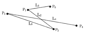
- 15 and 16 are diagrams for explaining a case where a code is encoded based on a distance other than a distance between adjacently arranged information dots.
- FIG. 15 uses the value of the distance from the start point information dot P0 to each information dot or the distance between the predetermined directions of the information dot as an index.
- the distance between information dots P0P1 is L1
- the distance between P0P2 is L2
- the distance between P0P3 is L3
- the distance between P0P4 is L4
- L1 to L4 are long and short.
- a code is encoded by a permutation of ranks, a combination of long and short ranks, a permutation of ratios, a combination of ratios, or at least one of an absolute value, a permutation of absolute values, and a combination of absolute values.
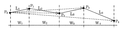
- the distance between the predetermined directions of P0 and P1 is W1
- the distance between the predetermined directions of P0 and P2 is W2
- the distance between the predetermined directions of P0 and P3 is W3 and P0.
- the distance between the predetermined directions of P4 is W4, and W1-W4 permutations of long and short ranks, combinations of long and short ranks, permutations of ratios, combinations of ratios, absolute values, permutations of absolute values, combinations of absolute values
- the code is encoded by at least one of them.
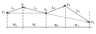
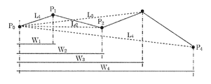
- FIG. 16 uses the value of the distance from the information dot P0 to each information dot or the distance between the information dots in a predetermined direction as an index.
- the distance between information dots P0P1 is L1
- the distance between P0P2 is L2
- the distance between P0P3 is L3
- the distance between P0P4 is L4
- L1 to L4 are long and short.
- a code is encoded by a permutation of ranks, a combination of long and short ranks, a permutation of ratios, a combination of ratios, or at least one of an absolute value, a permutation of absolute values, and a combination of absolute values.
- the distance between the horizontal directions of P0 and P1 is W1
- the distance between the horizontal directions of P0 and P2 is W2
- the distance between the horizontal directions of P0 and P3 is W3 and P0.
- the distance between the horizontal directions of P4 is W4, and W1-W4 is a permutation of long and short ranks, a combination of long and short ranks, a permutation of ratios, a combination of ratios, or an absolute value, a permutation of absolute values, a combination of absolute values
- the code is encoded by at least one of them.
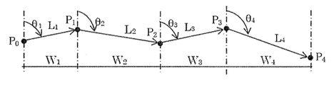
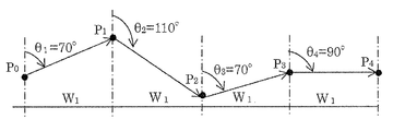
- FIG. 17, FIG. 18, FIG. 19, and FIG. 20 are diagrams illustrating a case where the distance between information dots is constant.
- the code is encoded by changing the distance between information dots or the like.
- the code is encoded by changing the rotation angle while keeping the distance between information dots and the like constant.
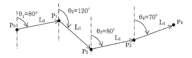
- FIG. 17 uses the angle between straight lines connecting adjacent information dots as an index.
- the rotation angle between a vertical line passing through P0 and a straight line (straight line P0P1) connecting P0 and P1 is ⁇ 1.
- a rotation angle between a straight line obtained by extending the straight line P0P1 in the right direction and the straight line P1P2 is defined as ⁇ 2.
- a rotation angle between a straight line obtained by extending the straight line P1P2 in the right direction and the straight line P2P3 is defined as ⁇ 3.
- a rotation angle between a straight line obtained by extending the straight line P2P3 in the right direction and the straight line P3P4 is ⁇ 4.
- Each rotation angle ⁇ 1, ⁇ 2, ⁇ 3, ⁇ 4 is a permutation of magnitude order, combination of magnitude order, ratio permutation, ratio combination, or absolute value, absolute value permutation, absolute value combination
- the code is encoded.
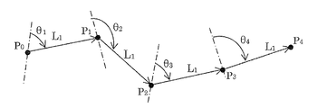
- FIG. 18 is a code encoded based on a rotation angle from a predetermined direction (a reference line indicated by a one-dot chain line) which is a reference of the rotation angle passing through each information dot.
- a straight line having an arbitrary inclination passing through the information dot P0 is provided, and the rotation angle formed by the straight line and the straight line P0P1 is ⁇ 1.
- a straight line having an arbitrary inclination passing through the information dot P1 is provided, and the rotation angle formed by the straight line and the straight line P1P2 is ⁇ 2.
- a straight line having an arbitrary inclination passing through the information dot P2 is provided, and the rotation angle formed by the straight line and the straight line P2P3 is ⁇ 3.
- a straight line having an arbitrary inclination passing through the information dot P3 is provided, and the rotation angle formed by the straight line and the straight line P3P4 is ⁇ 4.
- the slope of the straight line passing through each information dot is different for each information dot.
- Each rotation angle ⁇ 1, ⁇ 2, ⁇ 3, ⁇ 4 is a permutation of magnitude order, combination of magnitude order, ratio permutation, ratio combination, or absolute value, absolute value permutation, absolute value combination
- the code is
- FIG. 19 shows a code encoded based on a rotation angle with a predetermined direction (a reference line indicated by a one-dot chain line) as a reference for the rotation angle passing through each information dot as a vertical line.
- a vertical line passing through the information dot P0 is provided, and the rotation angle formed by the vertical line and the straight line P0P1 is ⁇ 1.
- a vertical line passing through the information dot P1 is provided, and the rotation angle formed by the vertical line and the straight line P1P2 is defined as ⁇ 2.
- a vertical line passing through the information dot P2 is provided, and the rotation angle formed by the vertical line and the straight line P2P3 is ⁇ 3.
- a vertical line passing through the information dot P3 is virtually provided, and the rotation angle formed by the vertical line and the straight line P3P4 is ⁇ 4.
- Each rotation angle ⁇ 1, ⁇ 2, ⁇ 3, ⁇ 4 is a permutation of magnitude order, combination of magnitude order, ratio permutation, ratio combination, or absolute value, absolute value permutation, absolute value combination
- the code is encoded.
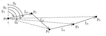
- FIG. 20 shows a code encoded with reference to a rotation angle formed by a straight line passing through the start point information dot and a straight line connecting the start point information dot and other information dots.
- a vertical line passing through the starting point information dot P0 is provided.
- a rotation angle formed by the vertical line and the straight line P0P1 is defined as ⁇ 1.
- the rotation angle formed by the vertical line and the straight line P0P2 is ⁇ 2
- the rotation angle formed by the vertical line and the straight line P0P3 is ⁇ 3
- the rotation angle formed by the vertical line and the straight line P0P4 is ⁇ 4.
- Each rotation angle ⁇ 1, ⁇ 2, ⁇ 3, ⁇ 4 is a permutation of magnitude order, combination of magnitude order, ratio permutation, ratio combination, or absolute value, absolute value permutation, absolute value combination
- the code is encoded.
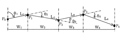
- FIG. 22, FIG. 23, and FIG. 24 are diagrams for explaining the case where the distance between the predetermined directions of the information dots is constant.
- the code is encoded by changing the distance between the information dots or the predetermined direction.
- the distance in the predetermined direction of the information dot is constant at W1
- the code is encoded by varying the rotation angle.
- FIG. 21 uses the rotation angle formed by the straight lines connecting adjacent information dots as an index.
- the rotation angle between a vertical line passing through P0 and a straight line (straight line P0P1) connecting P0 and P1 is ⁇ 1.
- a rotation angle between a straight line obtained by extending the straight line P0P1 in the right direction and the straight line P1P2 is defined as ⁇ 2.
- a rotation angle between a straight line obtained by extending the straight line P1P2 in the right direction and the straight line P2P3 is defined as ⁇ 3.
- a rotation angle between a straight line obtained by extending the straight line P2P3 in the right direction and the straight line P3P4 is ⁇ 4.
- Each rotation angle ⁇ 1, ⁇ 2, ⁇ 3, ⁇ 4 is a permutation of magnitude order, combination of magnitude order, ratio permutation, ratio combination, or absolute value, absolute value permutation, absolute value combination
- the code is encoded.
- FIG. 22 shows a code encoded based on a rotation angle from a predetermined direction (a reference line indicated by a one-dot chain line) that is a reference of the rotation angle passing through each information dot.
- a straight line having an arbitrary inclination passing through the information dot P0 is provided, and the rotation angle formed by the straight line and the straight line P0P1 is ⁇ 1.
- a straight line having an arbitrary inclination passing through the information dot P1 is provided, and the rotation angle formed by the straight line and the straight line P1P2 is ⁇ 2.
- a straight line having an arbitrary inclination passing through the information dot P2 is provided, and the rotation angle formed by the straight line and the straight line P2P3 is ⁇ 3.
- a straight line having an arbitrary inclination passing through the information dot P3 is provided, and the rotation angle formed by the straight line and the straight line P3P4 is ⁇ 4.
- the slope of the straight line passing through each information dot is different for each information dot.
- Each rotation angle ⁇ 1, ⁇ 2, ⁇ 3, ⁇ 4 is a permutation of magnitude order, combination of magnitude order, ratio permutation, ratio combination, or absolute value, absolute value permutation, absolute value combination
- the code is
- FIG. 23 is a code encoded based on a rotation angle with a predetermined direction (a reference line indicated by a one-dot chain line) as a reference for the rotation angle passing through each information dot as a vertical line.
- a vertical line passing through the information dot P0 is provided, and the rotation angle formed by the vertical line and the straight line P0P1 is ⁇ 1.
- a vertical line passing through the information dot P1 is provided, and the rotation angle formed by the vertical line and the straight line P1P2 is defined as ⁇ 2.
- a vertical line passing through the information dot P2 is provided, and the rotation angle formed by the vertical line and the straight line P2P3 is ⁇ 3.
- a vertical line passing through the information dot P3 is provided, and the rotation angle formed by the vertical line and the straight line P3P4 is ⁇ 4.
- Each rotation angle ⁇ 1, ⁇ 2, ⁇ 3, ⁇ 4 is a permutation of magnitude order, combination of magnitude order, ratio permutation, ratio combination, or absolute value, absolute value permutation, absolute value combination
- the code is encoded.
- FIG. 24 shows a rotation made by a straight line connecting the start point information dot and each other information dot, with a predetermined direction (reference line indicated by a one-dot chain line) as a reference of the rotation angle passing through the start point information dot as a vertical line.
- the code is encoded with reference to the corner.
- a vertical line passing through the starting point information dot P0 is provided.
- a rotation angle formed by the vertical line and the straight line P0P1 is defined as ⁇ 1.
- the rotation angle formed by the vertical line and the straight line P0P2 is ⁇ 2
- the rotation angle formed by the vertical line and the straight line P0P3 is ⁇ 3
- the rotation angle formed by the vertical line and the straight line P0P4 is ⁇ 4.
- Each rotation angle ⁇ 1, ⁇ 2, ⁇ 3, ⁇ 4 is a permutation of magnitude order, combination of magnitude order, ratio permutation, ratio combination, or absolute value, absolute value permutation, absolute value combination
- the code is encoded.
- 25 and 26 are diagrams for specifically explaining a method of encoding a code based on a distance.
- a sequence of numerical values (absolute values) to which distance values are assigned a numerical permutation, a combination of numerical values, a permutation of long and short ranks of distance values, and a combination of long and short ranks
- the code is encoded by at least one of the above.
- FIG. 25 is a diagram for explaining a case where a code is encoded by a numerical value.
- the code encoded in the dot pattern is 6759.
- the code encoded in the dot pattern is 6458.
- code is encoded in the same way as the decimal system.
- 10 ⁇ 9 ⁇ 8 ⁇ 7 5040 when coded by permutation
- 10 ⁇ 9 ⁇ 8 ⁇ 7/4 ⁇ 3 when coded by combination.
- * 2 * 1 210 codes can be encoded.
- the same distance is included in the distance value, the number of combinations is further increased.
- an actual distance value may be assigned.
- the reading is often performed with the optical reading device tilted. In that case, the actual distance value changes. For this reason, it is preferable to assign a numeric value representative when the value is within a predetermined range instead of the actual distance.
- FIG. 26 is a diagram illustrating a case where a code is encoded by a permutation combination of long and short ranks of distance values.
- the distance value when the distance value is directly used, it is necessary to accurately measure the distance between dots. However, it is not easy to accurately measure the distance between dots due to distortion of the paper surface or deviation during printing. Therefore, by analyzing only the distance length, the dot pattern can be read and decoded even if an accurate distance is not required.
- 27, 28, 29, and 30 show specific examples of encoding according to the order of distances.
- the codes 25 to 60 are assigned to combinations when there are two same distances, that is, when the first to third places exist.
- codes 61 to 74 are assigned for combinations where there are three same distances, that is, when there are first and second places.
- a code 75 is assigned for all cases where the distance is the same, that is, for all cases where the ranking is the same.
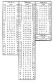
- FIG. 31 is a table showing such code assignment.
- code assignment in FIG. 31 is merely an example, and what code value is assigned to the combination case is arbitrary.
- 32, 33, 34, and 35 are diagrams illustrating a method for encoding a code based on a rotation angle.
- FIG. 32 is a diagram for explaining a case where a code is encoded by a numerical value of a rotation angle in a dot pattern in which the distance between information dots is constant.
- FIG. 33 is a diagram for explaining a case where a code is encoded with a numerical value of a rotation angle in a dot pattern in which the distance between information dots in a predetermined direction is constant.
- the numerical value to be assigned may be an actual rotation angle value.
- the reading is often performed with the optical reading device tilted. In this case, the actual rotation angle value changes. For this reason, it is preferable to assign a numerical value typified by a value within a predetermined range instead of an actual rotation angle.
- FIG. 34 is a diagram for describing a case where a code is encoded by a permutation combination of magnitudes of rotation angle values in a dot pattern in which the distance between information dots is constant.
- the number of rotation angle sections is coded in a permutation combination of 1st to 4th, 1st to 3rd, 1st to 2nd, all in the same order.
- FIG. 35 is a diagram for explaining a case where a code is encoded by a permutation combination of magnitudes of rotation angle values in a dot pattern in which the distance between horizontal directions of information dots is constant.
- the number of rotation angle sections is coded in a permutation combination of 1st to 4th, 1st to 3rd, 1st to 2nd, all in the same order.
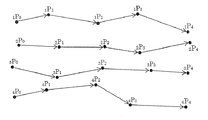
- FIG. 36 shows a code obtained by encoding a plurality of the above-described dot patterns in a band shape.
- a plurality of dot patterns according to the present invention can be arranged in the vertical and horizontal directions, and a single code can be encoded by a group of a plurality of dot patterns.
- the dot pattern of this embodiment is a dot pattern composed of a plurality of rows and a plurality of columns.
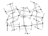
- FIG. 37 is a diagram showing a dot pattern of the present invention.
- the dot pattern includes a plurality of information dots arranged in a plurality of rows and a plurality of columns.
- This dot pattern is a code encoded, and the arrangement of information dots is determined so that each dot pattern encoded with a different code has a distance between adjacent information dots. .
- the distance between information dots arranged adjacently in each row and each column, permutation of long and short ranks, combination of long and short ranks, permutation of ratios, combination of ratios, or absolute is encoded by at least one of a value, a permutation of absolute values, and a combination of absolute values.
- the dot pattern is a permutation of long and short ranks, a combination of long and short ranks, a permutation of ratios, a permutation of ratios, and a combination of ratios.
- the code is encoded based only on at least one of absolute values, permutations of absolute values, and combinations of absolute values. Accordingly, it is possible to dramatically increase the number of codes that can be encoded by arranging a two-dimensional belt-like dot pattern and combining the number of codes that can be defined by each belt-like dot pattern in each row and each column.
- the relative distance between adjacent dots is determined.
- the advantage of the present invention is that the information is encoded based only on the evaluation. (1) The dot pattern reading calculation can be simplified and the speed can be increased. (2) Since it is difficult to visually decode the code, security can be improved. (3) The amount of information with a small number of dots can be increased. This contributes to solving the problem.
- this dot pattern is usually connected at predetermined intervals in the vertical and horizontal directions.
- the dot pattern is printed on paper (or displayed by display means), the dot pattern is photographed with a camera device, and the code can be decoded by analyzing the image data with a processor.
- the analysis of the image data extracts information dots from the image data, calculates the value of the distance between the adjacent information dots, the permutation of the long and short ranks of the distance value between the information dots, the long and short rank , A permutation of ratios, a combination of ratios, or a code corresponding to an absolute value, a permutation of absolute values, and a combination of absolute values.
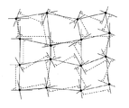
- FIG. 38 is a diagram for explaining a case where a code is encoded based on a distance between predetermined directions of information dots in the dot pattern of FIG.
- each row and each column obtains a distance between the predetermined directions in a predetermined direction of each start point information dot. Since the method for obtaining the distance between the predetermined directions is the same as that described in the first embodiment, the description thereof is omitted here.
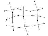
- the dot pattern described in the first embodiment is arranged in a plurality of rows and a plurality of columns, and shares information dots arranged adjacent to each other in each row and each column.
- This is a dot pattern in which both rows and columns are configured.
- the number of information dots can be reduced. Thereby, it is possible to reduce the dot density and further increase the amount of information.
- a part of information dots may be a dot pattern that constitutes one of a row and a column.
- FIG. 40 shows a dot pattern in which a code is encoded based on a distance between predetermined directions of information dots.
- Each row and each column obtains the distance between the predetermined directions in the predetermined direction possessed by the starting point information. Since the method for obtaining the distance between the predetermined directions is the same as that described in the first embodiment, the description thereof is omitted here.
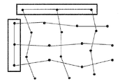
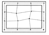
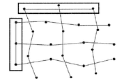
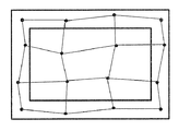
- FIG. 41 shows a dot pattern in which start point information dots (or end point information dots) arranged in the uppermost row and the leftmost column are reference dots arranged at predetermined intervals on virtual reference lines orthogonal to the row or column. It is a figure explaining.
- the reference dots may be arranged in the lowermost row and the rightmost column. That is, the start point information dots (or end point information dots) in any one of the upper and lower end portions and any one of the left and right end portions may be used as a row and a column in which the reference dots are arranged.
- the start point information dots and end point information dots in the upper and lower end rows and the left and right end columns may be used as the rows and columns in which the reference dots are arranged. Also, as shown in FIG.
- the start point information dots and end point information dots in the left and right end rows may be used as rows in which reference dots are arranged.
- the start point information dot (or end point information dot) in the left end column or the right end column may be a column in which the reference dots are arranged. Note that not all of the columns or rows in which the start point information dots (or end point information dots) are arranged are used as reference dots, but only a part of them may be used as reference dots although not shown.
- the reference dots may be any arrangement and number as long as the arrangement can specify the direction of the dot pattern. It should be noted that at least one reference dot is preferably arranged to represent the dot pattern. When one reference dot is used, a straight line (direction) including the reference dot must be defined. This straight line (direction) may be calculated based on the direction of the dot pattern.
- the dot pattern is arranged in a plurality of rows and a plurality of columns, and information rows arranged adjacent to each other in each row and each column are shared so that both the rows and the columns are configured.
- FIG. 5 is a diagram for explaining a dot pattern in which reference dots are arranged at end portions.
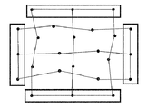
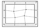
- FIG. 45 shows a dot pattern in which start point information dots and end point information dots arranged in upper and lower rows and left and right columns are reference dots arranged at predetermined intervals on virtual reference lines orthogonal to the rows or columns. It is a figure explaining.
- FIG. 46 shows a dot pattern in which start point information dots (or end point information dots) arranged in the uppermost row and the leftmost column are reference dots arranged at predetermined intervals on virtual reference lines orthogonal to the row or column. It is a figure explaining.
- the reference dots may be arranged in the lowermost row and the rightmost column. That is, any row at the upper and lower end portions and any column at the left and right end portions may be the rows and columns in which the reference dots are arranged.
- a code is encoded based on the value of the distance between information dots arranged adjacent in the row direction and the column direction.
- the start point information dots and end point information dots in the upper and lower end rows may be the rows in which the reference dots are arranged.
- the start point information dot (or end point information dot) in the uppermost row may be a row in which the reference dot is arranged.
- FIG. 49 is a diagram for explaining a dot pattern in which reference dots are further arranged at positions where virtual reference lines orthogonal to rows or columns intersect in the dot pattern of FIG.
- FIG. 50 is a diagram for explaining a dot pattern in which reference dots are further arranged at positions where virtual reference lines orthogonal to rows or columns intersect in the dot pattern of FIG.
- 51, 52, 53, and 54 are diagrams for explaining the definition of the direction of the dot pattern.
- the analysis result of the processor and the result of the process to be executed differ depending on which direction is the normal position, that is, the reference for recognizing the dot pattern. Therefore, it is preferable to define the direction of the dot pattern in order to recognize which direction is used to form the dot pattern. In particular, as will be described later, when arranging a plurality of dot patterns connected or connected, it is extremely important to recognize the direction of the dot pattern.
- FIG. 51 is a modification of the dot pattern of FIG. 42, and the reference dots on the virtual reference line (dashed line) with respect to the center between the reference dots at both ends arranged on the virtual reference line (dashed line).
- FIG. 6 is a diagram for explaining a dot pattern in which the predetermined interval is defined so that the direction of the dot pattern is defined so that is asymmetrical.
- the direction of the dot pattern can be determined by making the left and right (or top and bottom) asymmetric.
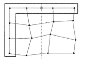
- FIG. 52 is a modification of the dot pattern of FIG. 41, and the reference dot on the virtual reference line (dashed line) with respect to the center between the reference dots at both ends arranged on the virtual reference line (dashed line).
- FIG. 6 is a diagram for explaining a dot pattern in which the predetermined interval is defined so that the direction of the dot pattern is defined so that is asymmetrical.
- the reference dots are arranged only on one side. However, if a plurality of dot patterns are arranged at a predetermined interval, the reference dots are arranged vertically and horizontally, and the reference dots are apparently symmetrical vertically and horizontally. Then, it becomes difficult to recognize the direction of the dot pattern. Therefore, the direction of the dot pattern can be determined by making the top and bottom (or left and right) asymmetric.
- FIG. 53 is an example in which the arrangement of the reference dots of the dot pattern of FIG. 49 is changed, and for the one-dot chain line that intersects at right angles at the center between the reference dots at both ends arranged on the virtual reference line in the vertical direction, It is a figure explaining the dot pattern in which the predetermined interval was defined and the direction of the dot pattern was defined so that the reference dots on the virtual reference line are vertically asymmetric.
- the direction of the dot pattern can be determined by making the top and bottom (or left and right) asymmetric.
- FIG. 54 is an example in which the arrangement of the reference dots of the dot pattern of FIG. 50 is changed, and the virtual reference line (one point) with respect to the center between the reference dots at both ends arranged on the virtual reference line (one-dot chain line). It is a figure explaining the dot pattern in which the predetermined interval was defined and the direction of the dot pattern was defined so that the reference dots on the chain line were left-right asymmetric.
- the reference dots are arranged only on one side. However, if a plurality of dot patterns are arranged at a predetermined interval, the reference dots are arranged vertically and horizontally, and the reference dots are apparently symmetrical vertically and horizontally. Then, it becomes difficult to recognize the direction of the dot pattern. Therefore, the direction of the dot pattern can be determined by making the left and right (or top and bottom) asymmetric.
- FIG. 55 is an example in which the arrangement of the reference dots in the dot pattern of FIG. 42 is changed.
- the dot pattern in which the reference dots arranged on the virtual reference line are arranged shifted in a predetermined direction and the direction of the dot pattern is defined. It is a figure explaining about.
- the direction of the dot pattern can be defined by the deviation of the reference dot.
- the direction of the dot pattern can be recognized.
- the reference dots are shifted on the right side, it is a matter of design whether the direction of the dot pattern is up, down, left, or right.
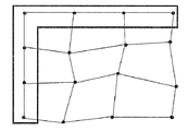
- FIG. 56 is an example in which the arrangement of the reference dots in the dot pattern of FIG. 41 is changed.
- the dot pattern in which the reference dots arranged on the virtual reference line are arranged shifted in a predetermined direction and the direction of the dot pattern is defined. It is a figure explaining about.
- the reference dots are arranged only on one side. However, if a plurality of dot patterns are arranged at a predetermined interval, the reference dots are arranged vertically and horizontally, and the reference dots are apparently symmetrical vertically and horizontally. Then, it becomes difficult to recognize the direction of the dot pattern. Therefore, the direction of the dot pattern can be defined by the deviation of the reference dot.
- FIG. 57 shows an example in which the arrangement of the reference dots of the dot pattern of FIG. 49 is changed.
- the dot pattern in which the reference dots arranged on the virtual reference line are arranged shifted in a predetermined direction and the direction of the dot pattern is defined. It is a figure explaining about.
- the direction of the dot pattern can be defined by the deviation of the reference dot.
- the reference dots arranged at the four corners of the dot pattern are shifted upward, the direction of the dot pattern can be recognized. Note that, when the reference dots are shifted and arranged on the upper side, it is a matter of design whether the direction of the dot pattern is up, down, left, or right.
- FIG. 58 is an example in which the arrangement of the reference dots of the dot pattern of FIG. 50 is changed.
- a dot pattern in which the reference dots arranged on the virtual reference line are arranged in a predetermined direction and the direction of the dot pattern is defined. It is a figure explaining about.
- the reference dots are arranged only on one side. However, if a plurality of dot patterns are arranged at a predetermined interval, the reference dots are arranged vertically and horizontally, and the reference dots are apparently symmetrical vertically and horizontally. Then, it becomes difficult to recognize the direction of the dot pattern. Therefore, the direction of the dot pattern can be defined by the deviation of the reference dot. In FIG. 58, since the reference dot arranged third from the top of the left end is shifted to the right, it can be recognized that the dot pattern is facing right. When the reference dots are shifted on the right side, it is a matter of design whether the direction of the dot pattern is up, down, left, or right.
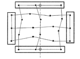
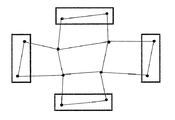
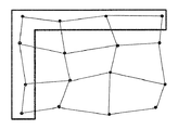
- FIG. 59 illustrates a dot pattern in which the start point information dots and the end point information dots arranged in the upper and lower rows and the left and right columns serve as reference dots arranged in a predetermined shape in a direction orthogonal to the row or column. It is a figure to do.
- codes are encoded based on distance values between adjacent information dots arranged in the row and column directions, and the orientation of the dot pattern is defined by the reference dot arrangement shape. Is done.
- the direction of the dot pattern is defined by a predetermined shape represented by the arrangement of all or part of the reference dots.
- This shape may be any shape as long as it is designed as a pattern in advance, but it may present a non-axial object that does not become the shape before rotation even if the shape is rotated 180 degrees around both ends of the reference dot.
- the direction of the dot pattern can be defined from the shape itself.
- an arrangement is preferable in which the arrangement shape of the reference dots can be distinguished from the arrangement shape of the band-shaped information dots.
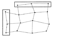
- FIG. 60 is a diagram for explaining a dot pattern in which the start point information dots and the end point information dots arranged in the uppermost row and the leftmost column serve as reference dots arranged in a predetermined shape in a direction orthogonal to the row or column. It is.
- the reference dots may be arranged in the lowermost row and the rightmost column. That is, any row at the upper and lower end portions and any column at the left and right end portions may be the rows and columns in which the reference dots are arranged.
- a code is encoded based on a distance value between information dots arranged adjacent in the row direction and the column direction, and the direction of the dot pattern is defined by the arrangement shape of the reference dots. .
- the reference dots are arranged only on one side.
- the reference dots are arranged vertically and horizontally, and the reference dots are apparently symmetrical vertically and horizontally. Then, it becomes difficult to recognize the direction of the dot pattern. Therefore, it is preferable that the direction of the dot pattern is defined by representing a predetermined shape by arranging all or part of the reference dots.
- This shape may be any shape as long as it is designed as a pattern in advance. However, the shape may be non-axisymmetric so that it does not become the shape before rotation even if the shape rotates 180 degrees around both ends of the reference dot.
- the direction of the dot pattern can be defined from the shape itself.
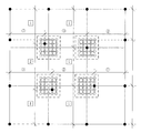
- FIG. 61 is a diagram for explaining the dot pattern in which the reference dots are arranged at positions shared outside the positions arranged in a predetermined shape in the direction orthogonal to the rows or columns in the dot pattern of FIG.
- the reference dots are arranged not in a straight line but in a predetermined shape, the reference dots are further arranged at positions where the row direction and the column direction in which the reference dots are arranged intersect. Is possible. Thereby, when a plurality of dot patterns are arranged, the dots are evenly arranged without missing dots, and the visual effect can be improved.
- FIG. 62 and 63 are diagrams for explaining the dot pattern in which the reference dot is arranged at a position shared outside the position arranged in a predetermined shape in the direction orthogonal to the row or column in the dot pattern of FIG. It is.
- the reference dots are arranged not in a straight line but in a predetermined shape, the reference dots are further arranged at positions where the row direction and the column direction in which the reference dots are arranged intersect. Is possible. As a result, when a plurality of dot patterns are arranged and arranged, the dots are evenly arranged without missing dots, and the visual effect can be improved.
- FIG. 63 is a diagram for explaining a case where a code is encoded based on a distance between predetermined directions of information dots.
- each row and each column calculates a distance between the predetermined directions in a predetermined direction of each start point information dot.
- the predetermined directions in the row direction and the column direction are respectively It is constant.
- the predetermined direction of the information dots arranged adjacent to the row direction is the vertical direction
- the predetermined direction of the information dots arranged adjacent to the column direction is the horizontal direction.
- the distance between the vertical lines of adjacent information dots is obtained.
- the distance between the horizontal lines of adjacent information dots is obtained.
- the vertical and horizontal lines are easy to set and analyze by the processor. Therefore, by setting the vertical direction for information dots adjacent in the row direction and the horizontal direction for information dots adjacent in the column direction, the processor can easily calculate the distance between the predetermined directions. Become.
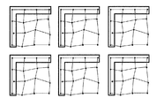
- the dot pattern shown in FIG. 64 is the dot pattern shown in FIG.
- the dot pattern shown in FIG. 65 is the dot pattern of FIG.
- the dot pattern shown in FIG. 66 is the dot pattern of FIG.
- the dot pattern shown in FIG. 67 is the dot pattern shown in FIG.
- 68 and 69 are diagrams for explaining how to define a predetermined direction of an information dot.
- the predetermined direction of the information dots arranged adjacent to each other in the row direction or the column direction is the direction of a line segment connecting two reference dots.
- the dot pattern shown in FIG. 68 is the dot pattern of FIG. 61, and is configured by 4 rows ⁇ 4 columns.
- the predetermined direction of the information dots arranged adjacent to the row direction of the second row is provided in a direction perpendicular to the line segment connecting the first and second reference dots from the top at each of the right end and the left end.
- the predetermined direction of the information dots arranged adjacent to the row direction of the third row is provided in a direction orthogonal to the line segment connecting the second and third reference dots from the top at each of the right end and the left end.
- the predetermined direction of the information dots arranged adjacent to the second column direction is provided in a direction perpendicular to the line segment connecting the first and second reference dots from the left at the upper end and the lower end, respectively.
- the predetermined direction of the information dots arranged adjacent to the third column direction is provided in a direction perpendicular to the line segment connecting the second and third reference dots from the left at the upper end and the lower end, respectively.
- the dot pattern shown in FIG. 69 is the dot pattern of FIG. 62, and is composed of 4 rows ⁇ 4 columns.
- the predetermined direction of the information dots arranged adjacent to the row direction is provided in a direction perpendicular to the line segment connecting the first and third reference dots from the top at the left end.
- the predetermined direction of the information dots arranged adjacent to each other in the column direction is provided in a direction perpendicular to the line segment connecting the first and third reference dots from the left at the upper end.
- the reference dots to be connected need not be adjacent reference dots.
- information may be defined for the reference dot.
- the distance between reference dots arranged adjacently or the distance between predetermined directions is a permutation of long and short ranks, a combination of long and short ranks, a permutation of ratios, a combination of ratios, or a permutation of absolute values and absolute values
- a numerical value is defined in at least one of the absolute value combinations.
- the reference dot at the left end has a permutation of distance values (8), (10), and (12) from the top.
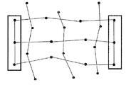
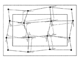
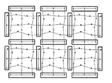
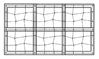
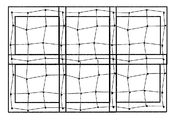
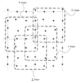
- the dot patterns shown in FIGS. 37, 41, and 58 described above are usually connected at predetermined intervals in the vertical and horizontal directions as shown in FIGS. 70, 71, and 72.
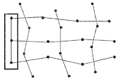
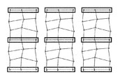
- the dot patterns having reference dots at both ends and the dot patterns shown in FIGS. 55, 53, and 61 are arranged at both ends of a plurality of rows and / or at both ends of a column as shown in FIGS. 73, 74, and 75.
- the reference dots thus arranged are arranged in the same shape, and the reference dots arranged in the same shape are overlapped and connected horizontally and vertically.
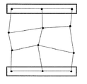
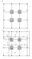
- the reference dots arranged at both ends of the plurality of rows and / or both ends of the columns are arranged in the same shape as shown in FIG. 76, and arranged in the same shape.
- a plurality of reference dots may be superimposed and connected in the left-right or up-down direction, and the other directions may be connected in a predetermined interval.
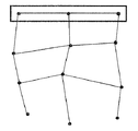
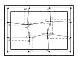
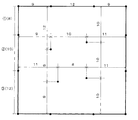
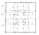
- the target dot pattern is composed of 4 rows ⁇ 4 columns, and the reference dot of the second row among the vertical reference dots arranged at equal intervals in the left and right columns is shifted upward to change the direction of the dot pattern. It has established.
- the horizontal reference dots arranged in the upper and lower rows are arranged at equal intervals.
- the reference dots in the second and third rows are connected up and down to form the first and second virtual vertical lines, and the second and third reference dots before the left and right columns are shifted are connected to the left and right.
- the first and second virtual horizontal lines are used.
- the arrangement interval is set to 1 in the vertical and horizontal directions as shown in FIG. A 5 ⁇ 5 virtual point for arranging information dots is arranged.
- the short and long (9, 10, 11), (9, 9, 12), (8, 11, 11), ( There are four, 10, 10, 10).
- the short and long ranks from the shortest order ((1), (2), (3)), ((1), (1), (2)), ((1), ( 2), (2)), ((1), (1), (1)).
- the increment of the distance in different predetermined directions is set with a difference of 10% or more in order from the shortest distance. This is based on the assumption that the error in the distance between information dots is about 5%, taking into account printing misalignment, printing medium distortion, and camera tilt (30 to 40 degrees) when reading the dot pattern. It was set so that the ranking of the distance between dots could be accurately determined. Thereby, if it is less than about 7.5%, it will determine as the same distance and can recognize that it is the same rank.
- the camera tilt which has the greatest effect on the deformation of the dot arrangement position, the above error varies depending on the camera resolution and lens performance, so the error should be set after a sufficient demonstration experiment based on the usage conditions. There is a need.
- the reference dots in the second row are shifted by two upwards.
- this row (8, 12, 10) is a vertical reference dot.
- the same amount of code as the permutation combination of the distances in the predetermined direction between the other three information dots can be set for the horizontal reference dot.
- 13 5 371,293 codes can be defined for all rows, columns, and horizontal reference dots.
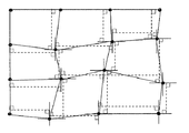
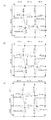
- FIG. 77 (b) is an example in which information dots are actually arranged.
- the distance between the reference dots is set to 10
- any numerical value may be used, and the deviation of the reference dots and the arrangement of the information dots may be set at the same ratio based on the numerical value between the reference dots.
- the distance between reference dots may be 10 pixels with a printing accuracy of 600 DPI.
- the dot size may be 1 pixel or 2 ⁇ 2 pixels. Considering the visual effect at the time of dot printing, 1 pixel is good, but if there is a large variation in printing, it can be set to 2 ⁇ 2 pixels so as not to lower the recognition rate.
- the leftmost reference dot has a permutation of distance values (8), (10), and (12) from the top.
- this permutation is a permutation of the distance between other dots.
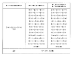
- the number of codes that can be expressed by a conventional dot pattern under the same conditions as in FIG. 78 will be described.
- the number of information dots is 4, when the code is expressed by a deviation in 8 directions from the reference point, 4 of 8
- the number of codes is 4096, and the number of codes is 16 to the fourth power and 65536 when the code is expressed by the deviation in 8 directions and the long and short distances.
- the number of codes that can be expressed is greatly improved.
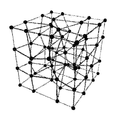
- the dot pattern composed of a plurality of rows and a plurality of columns has been described as the dot pattern of the second embodiment, a plurality of dots are arranged in the depth direction in addition to the row direction and the column direction as shown in FIG. It is also possible to generate a three-dimensional dot pattern having an original arrangement. In the figure, 32 reference dots are arranged along the eight edges of the cube, and 32 information dots are arranged inside. When codes are encoded by the same method as in FIGS. 77 to 79, the number of codes is 1372 at maximum.
- This three-dimensional dot pattern is a dot that can be physically recognized by a predetermined method, such as electrical, optical, or magnetic recognition, in solid (filled) solids or solids of flat members. Place.
- the elements may be integrated to store dots.
- the coordinate values (XYZ values) of the dots constituting the three-dimensional dot pattern can be stored as digital information and decoded. These are excellent in security because code information is not directly digitized.
- the implementation of the dot pattern of the second embodiment may include all implementations of the first embodiment
- the implementation of the dot pattern of the third embodiment may implement all implementations of the first and second embodiments. May include.
- the dot pattern described in the present invention is generated as image data by a program on a computer, and is formed on a printing surface by printing out on a printing medium such as paper.
- the method of forming the dot pattern on the product is not limited to using a printing apparatus, and any known output means may be used.
- a dot pattern may be displayed on a display device.
- the dot pattern can be decoded by using a reading device.
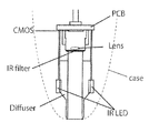
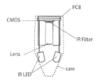
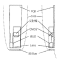
- the dot pattern reading apparatus includes at least an imaging unit for imaging a dot pattern, a processing unit, and a storage unit.
- the reading device refers to both the case where the imaging means, the processing means, and the storage means are provided in one casing, and the case where they are provided in a plurality of casings.
- the image pickup means includes a type that reads by bringing a reading device into contact with a medium on which a dot pattern is printed, and a type that reads while the reading device is separated from the medium.
- the pen type so-called electronic pen or voice pen the one equipped with the imaging means on the bottom of the figure
- the card reader In addition to what reads and prints a medium on which a dot pattern is printed, various scanners are all included.
- the method of reading with the reading device away from the medium includes all of those that are photographed with a camera built in a mobile phone, smartphone, tablet device, and those that are photographed with a normal camera.
- the storage means stores a program to be executed by the processing means. This program detects the dot pattern from the image data imaged by the imaging means and decodes the code encoded by the dot pattern. Processing and are included.
- the code is decoded based on the dot pattern encoding algorithm already described.
- the decrypted code can be used for the corresponding processing. What kind of processing is performed may be used for all kinds of processing.
- the information corresponding to the code may be read from the storage means and output.
- Information corresponding to the code may be retrieved from the Internet.
- the medium on which the dot pattern is formed can be used for a mouse pad, a tablet, a touch panel, a map, and the like.
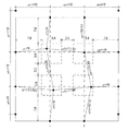
- FIG. 78 shows an example in which dot patterns are actually arranged in the above-described embodiment of FIG. 77, and FIG. 79 shows the number of code assignments that can be expressed by the present invention.
- the reference dots in the left column have a permutation of distance values (8), (10), and (12) from the top.
- this permutation can be distinguished from the others, and the direction and boundary of the dot pattern can be defined by the reference dots in the left column.
- a dot pattern composed of 4 rows ⁇ 4 columns is shown, but even if the number of rows and columns is increased, the dot pattern can be arranged by the same generation method.
- the virtual points 7 ⁇ 7 where the dots are arranged are set to 9 locations, as in FIG.
- a code can be encoded by uniquely setting a long and short permutation combination of distances in a predetermined direction.
- a method that can be uniquely encoded if the dots are arranged at predetermined positions As described above, if the following conditions are satisfied, there are at least one candidate position where dots are arranged, and dots may be arranged by any algorithm. This means that even with different dot arrangements, the same code can be encoded, it is difficult to decipher the code, and it can be said that the security is excellent.
- L 1, L 2, and L 3 need to be set so that L 1 ⁇ L 2 and L 2 ⁇ L 3 are determined even when distortion is considered.
- L 1 ⁇ L 1 , L 1 ⁇ L 2 Set to be judged.
- L 1 ⁇ L 1 Set to be judged.
- a threshold value ⁇ (1 / ⁇ ⁇ ⁇ , ⁇ > 1) is set for performing determination between information dots of the next shortest distance from the shorter distance in the predetermined direction between the information dots.
- This threshold ⁇ is used when decoding the code.
- ⁇ L 1 ⁇ L 2 ⁇ L 1 , ⁇ L 2 ⁇ L 3 ⁇ L 2 L 1 ′ generated as the same distance as L 1 having the shortest distance in the predetermined direction between the information dots or L 2 ′ generated as the same distance as the second short L 2 must be the same distance.
- the distance in the predetermined direction between the information dots is determined with respect to the magnification ⁇ due to the deformation due to the deformation of the information dots of the captured image and the printing deviation when the camera is tilted, and the distortion of the print medium.
- the safety factor design increment rate with respect to the error increment rate
- the above safety factor is determined by how much the camera is tilted, how much printing misalignment occurs, how much distortion of the printing medium occurs, and how much the misperception rate is suppressed.
- the safety factor may be arbitrarily determined.
- the long and short ranks are assigned based on the distance in the predetermined direction between the information dots and the codes are encoded by the permutation combination, only the distance comparison is performed.
- the code can be encoded using the distance value itself.
- the numerical value of the set distance at the time of dot pattern generation is D
- the error due to the deformation of the information dot arrangement of the captured image and the printing deviation when the camera is tilted, the error due to the distortion of the printing medium is also considered.
- ⁇ 1 and ⁇ 2 are set as absolute values
- D can be specified from ⁇ 1 ⁇ D ⁇ ⁇ 2 .
- this method may be used to search for a reference dot having a distance between reference dots that is different from a distance in a predetermined direction between information dots.
- the numerical value of the predetermined distance between the read information dots and the rank order of the distance can be used in combination.
- the dot pattern generation method for encoding a code with a long and short permutation combination of information dots in a predetermined direction and the encoding of the code have been described.
- the encoding conditions of the above (1) to (6) are as follows.
- the present invention can also be applied to a dot pattern in which a code is encoded by a permutation combination of long and short distances between information dots.
- the representative point of the dot is obtained from the coordinate value of the pixel constituting the dot.
- the center coordinate value (average coordinate value) of the dots may be obtained by simply adding the XY coordinate values of the pixels and dividing by the number of pixels constituting the dot, and may be used as the coordinate value of the representative point.
- weighting is performed for each pixel at the darkness level, and the coordinate value of the representative point of the dot by the above method. You may ask for.
- the first dot arrangement on the straight line is searched for, and the second dot arrangement on the straight line intersecting the first dot is searched.
- the above intersection is usually orthogonal, but when the dot pattern is imaged by tilting the optical reader with respect to the paper surface, the orthogonality is not maintained, so it is considered to intersect at an angle within a predetermined range. You have to look for the second dot sequence.
- a reference dot arrangement for specifying the direction of the dot pattern is searched for from the arrangement of the first or second dots.
- the search method is such that the distance between reference dots is D n (where n is the number indicating which reference dot), thresholds n ⁇ 1 and n ⁇ 2 are set as absolute values, and n ⁇ 1 ⁇ D ⁇ n ⁇ Specify D n from 2 and search for the reference dot sequence.
- the arrangement of the information dots in the row direction and the column direction is known, and in the row direction and the column direction, a predetermined direction between each information dot from the reference dot that is the start point information dot
- the ranking of the distances is calculated by the above-described comparison formula.
- the area surrounded by the reference dots arranged in a rectangle is not necessarily required for the calculation, and as shown in the broken line frame in FIG. They may be arranged in a + shape, an H shape, or a D shape. This is because the order of the distances between the information dots in the predetermined direction can be calculated in the same manner if the necessary information between the information dots in the row direction and the column direction is included in the calculation area without omission.
- FIG. 87 shows an example of a dot pattern generated at a distance between information dots, but it goes without saying that the same applies to a dot pattern generated at a distance in a predetermined direction between information dots.
- the code may indicate at least one code value or may be a coordinate value.
- the code value and the coordinate value may be included.
- the coordinate value may be a coordinate value based on various coordinate systems such as an XY coordinate value and an XYZ coordinate value.
- the area indicated by the broken line is the maximum area in which the information dot is located when reading the dot pattern, and printing misalignment, print medium distortion, and camera tilt when reading the dot pattern ( This is an area in consideration of deformation of the dot arrangement by 30 to 40 degrees.
- the dot pattern reading method and code decoding for decoding codes with long and short permutations of distances in a predetermined direction between information dots have been described, but the reading methods (1) to (7) and code Decoding can also be applied to dot patterns in which codes are decoded with long and short permutations of distances between information dots.
- the target dot pattern is composed of 4 rows ⁇ 4 columns with reference dots arranged in both ends and columns, and the first and fourth rows of vertical reference dots arranged at equal intervals in the left and right columns.
- the direction of the dot pattern is determined by shifting the reference dot of the eye upward.
- the horizontal reference dots arranged in the upper and lower rows are arranged at equal intervals.
- the method of determining the direction of the dot pattern is to determine the direction of the dot pattern by shifting the reference dots in the first and fourth rows upward among the vertical reference dots arranged at equal intervals in the upper and lower rows. It goes without saying that it is equivalent to.
- the distance between the reference dots having a distance different from the distance in the predetermined direction between the information dots is used.
- the reference dot in the left column has a permutation of distance values (12), (10), and (8) from the top.
- the orientation and boundary of the dot pattern can be defined by the arrangement of the reference dots in the left column aligned on a straight line.
- the interval between the reference dots adjacent to the information dots is equal, but any arrangement may be used as long as the reference dots can be specified as a pattern.
- the distance between information dots cannot be arbitrarily determined and arranged uniquely. For this reason, the distance in the predetermined direction between the information dots set in FIG. 77 is used as an initial value, and based on the conditions for the length of the distance described in ⁇ Second Example of Dot Pattern Generation Method and Code Encoding>. If the condition is not met, the position of the corresponding information dot is shifted and corrected, and the code is encoded by the permutation combination of the distance.
- the combinations between the three information dots are the long and short order from the shortest order (number (1), (2), (3)), ((1), (1), (2)), ((1) number, (2) number, (2) number), ((1) number, (1) number, (1) number).
- the above combinations are (9,10,11), (9,9,12), (8,11,11), (10,10,10) total at a distance in a predetermined direction. Therefore, these are set as 30 or more, and these are used as the initial value of the distance from the reference dot to the information dot.
- the information dot P 12 is 2
- the distance between the information dots is (9, 11.11, 10) for the two rows (11, 11.08, 8) for the two rows, In a sequence (9, 12.28, 9), in a 3-column sequence, (10, 10.39, 10).
- ⁇ 0.95
- ⁇ second embodiment> 1.105.
- 12 r 1, 12 r 2 (, 12 r 3) correction 11,11.09,8), as shown in FIG. 85 (c)
- 12 r 1 , 12 r 2 , 12 r 3 are (11.045, 11.05, 8), and 12 r 1 , 12 r 2 are almost the same.
- dot patterns can be similarly generated by this method even with other reference dot arrangements.
- the dot pattern arrangement may be generated by any method. Furthermore, instead of determining the dot arrangement at the time of dot pattern generation, information dot arrangements that reproduce the distances of information dots of all combinations are calculated in advance and stored in a table. It may be generated.
- a dot pattern composed of 4 rows ⁇ 4 columns is shown, but even if the number of rows and columns is increased, the dot pattern can be arranged by the same generation method.
- a dot pattern composed of 5 rows ⁇ 5 columns there are nine information dots excluding the reference dots, and the four information dots arranged in the nine inner corners are two reference dots.
- the initial value of the distance between the information dots is set as in FIG.
- an information dot positioned between two corner information dots in the row or column direction has a distance set by an initial value from either one adjacent reference dot or two corner information dots. Find the intersection of circles drawn as radii.
- an intersection with the information dot at the other corner is obtained, and an intermediate value between the two intersections is arranged as an information dot located between the information dots at the two corners.
- the position of the information dot located near the center is obtained by a similar method. Thereafter, the position of the information dots is corrected by shifting until the conditions are met, the arrangement of nine information dots is set, and encoding is performed with long and short permutations of the distance between all the information dots.
- This reading method is exactly the same as the dot pattern reading method described in (1) to (7) of ⁇ Dot pattern reading method generated based on the distance in the predetermined direction between information dots and code decoding>. Yes, the description of “distance between information dots in a predetermined direction” may be read as “distance between information dots”.
- the area indicated by the broken line in FIG. 86 is the maximum area where the information dot is located when reading with the camera.
- ⁇ a method of reading a dot pattern generated based on a distance in a predetermined direction between information dots and decoding of a code> (1) to (7) may be performed.
- ⁇ can be set close to 1.
- the visual effect can be improved by suppressing the pattern generated when the information dot arrangement is unevenly distributed.
- the present method it is possible to finely set the stage of setting the distance between the information dots in a predetermined direction and the distance between the information dots, and more information can be defined.
- a process of reading the above dot pattern, calculating the length order of the distance in the predetermined direction between the information dots or the distance in the predetermined direction between the information dots, and decoding the program is a program built in the optical reader (camera) and / or Or implemented by a circuit.
- the IR sensor irradiates infrared light onto the medium surface, and the reflected light from the medium surface is condensed with the lens through the IR filter, and the CMOS sensor. To be imaged. Note that by irradiating a considerably strong infrared light, it is also possible to take an image with a pinhole without using Lens. 88 and 89, uniform infrared light irradiation onto the medium surface is realized by irradiating the medium surface with the infrared light emitted from the IR-LED through the Diffuser.
- the intensity of the infrared light that is specularly reflected on the medium surface is reduced, and dots are reliably imaged without causing highlights in the captured image. Furthermore, even when the pen is tilted, it is possible to ensure brightness that allows dots to be recognized even in an area far from the installation point of the pen and the medium surface.
- the IR LED is arranged at a position close to the medium surface, so that no highlight is generated near the center of the captured image.
- the irradiated light may be light of other frequencies instead of infrared light. What is important is that any form may be used as long as light can be applied and the reflected light can be imaged to recognize the dots.
- the irradiation light may be natural light or visible light, and the dots may be recognized by image processing or the like.
- the code decoded by the optical reader is transmitted from the optical reader to electronic devices such as various PCs, mobile phones, smartphones, TVs, STBs, audio devices, game consoles, and IPs wirelessly or by wire, and corresponding processing is performed. Is done.
- Information corresponding to the decrypted code may be transmitted.
- the optical reading device may perform only the imaging of the dot pattern, and the captured dot pattern image may be transmitted to the electronic device or the like and decoded by the electronic device.
- information corresponding to the decoded code may be read and output from a storage medium provided inside or outside.
- the information corresponding to the code may not be data but may be an address, a file name, or a processing instruction in which the information is stored.
- These codes and information can be transmitted to the server (cloud) via the Internet, and the corresponding information can be transmitted from the server to the above-described electronic device or optical reading device, and further corresponding processing can be performed.
- the present invention can record a large amount of information with a low dot density, and since the recorded information cannot be easily decoded by a third party from the coordinate value where the dots are arranged, the security system, forgery prevention, and billing It can be widely used for music and video purchase / distribution and catalog shopping.
- the industrial applicability of the present invention is not limited to the above, and may be used in various modes such as a conventional educational system, a toy, and a game.
Landscapes
- Engineering & Computer Science (AREA)
- Theoretical Computer Science (AREA)
- Physics & Mathematics (AREA)
- General Physics & Mathematics (AREA)
- Databases & Information Systems (AREA)
- Data Mining & Analysis (AREA)
- General Engineering & Computer Science (AREA)
- Electromagnetism (AREA)
- Health & Medical Sciences (AREA)
- General Health & Medical Sciences (AREA)
- Toxicology (AREA)
- Artificial Intelligence (AREA)
- Computer Vision & Pattern Recognition (AREA)
- Image Processing (AREA)
- Editing Of Facsimile Originals (AREA)
- Compression Or Coding Systems Of Tv Signals (AREA)
Priority Applications (6)
| Application Number | Priority Date | Filing Date | Title |
|---|---|---|---|
| KR1020157009122A KR20150063421A (ko) | 2012-10-01 | 2013-10-01 | 도트 패턴, 도트 패턴 형성 매체, 도트 패턴의 화상 데이터를 생성하는 프로그램, 도트 패턴 형성 장치, 광학 장치, 광학 판독 장치, 정보 입출력 장치, 도트 패턴 판독 장치 |
| EP13843900.5A EP2905727A4 (en) | 2012-10-01 | 2013-10-01 | POINT PATTERN, POINT PATTERN FORMING MEDIUM, POINT PATTERN PICTURE DATA PROGRAM, POINT PATTERN DEVICE DEVICE, OPTICAL DEVICE, OPTICAL DEVICE READER, I / O DEVICE, POINT PATTERN READER |
| CN201380051656.XA CN105122275B (zh) | 2012-10-01 | 2013-10-01 | 点阵图形形成媒介 |
| JP2014539763A JP6533895B2 (ja) | 2012-10-01 | 2013-10-01 | ドットパターン、ドットパターン形成媒体、ドットパターンの画像データを生成するプログラム、ドットパターン形成装置、光学装置、光学読み取り装置、情報入出力装置、ドットパターン読み取り装置 |
| US14/432,936 US20150262051A1 (en) | 2012-10-01 | 2013-10-01 | Dot pattern, dot pattern formation medium, program generating image data of dot pattern, dot pattern formation device, optical device, optical reading device, information input/output device, dot pattern reading device |
| PH12015500941A PH12015500941A1 (en) | 2012-10-01 | 2015-04-28 | Dot pattern, dot-pattern-forming medium, program for generating image data for dot pattern, dot pattern forming apparatus, optical device, optical device reader, information i/o device, dot pattern reader |
Applications Claiming Priority (4)
| Application Number | Priority Date | Filing Date | Title |
|---|---|---|---|
| JP2012219902 | 2012-10-01 | ||
| JP2012-219902 | 2012-10-01 | ||
| JP2012244923A JP5344328B1 (ja) | 2012-10-01 | 2012-11-06 | ドットパターン、ドットパターン形成媒体、ドットパターンの画像データを生成するプログラム、ドットパターン形成装置、光学装置、光学読み取り装置、情報入出力装置、ドットパターン読み取り装置 |
| JP2012-244923 | 2012-11-06 |
Publications (1)
| Publication Number | Publication Date |
|---|---|
| WO2014054647A1 true WO2014054647A1 (ja) | 2014-04-10 |
Family
ID=49764843
Family Applications (1)
| Application Number | Title | Priority Date | Filing Date |
|---|---|---|---|
| PCT/JP2013/076722 WO2014054647A1 (ja) | 2012-10-01 | 2013-10-01 | ドットパターン、ドットパターン形成媒体、ドットパターンの画像データを生成するプログラム、ドットパターン形成装置、光学装置、光学読み取り装置、情報入出力装置、ドットパターン読み取り装置 |
Country Status (7)
Cited By (3)
| Publication number | Priority date | Publication date | Assignee | Title |
|---|---|---|---|---|
| CN103945125A (zh) * | 2014-04-14 | 2014-07-23 | 立德高科(北京)数码科技有限责任公司 | 能够对点阵图形图像进行分析的摄像装置及其方法 |
| EP3045214A1 (en) | 2015-01-14 | 2016-07-20 | Cartamundi Turnhout N.V. | Board game with pattern recognition |
| CN107533655A (zh) * | 2015-04-30 | 2018-01-02 | 雀巢产品技术援助有限公司 | 用于制备饮料或食品的系统的代码和容器 |
Families Citing this family (10)
| Publication number | Priority date | Publication date | Assignee | Title |
|---|---|---|---|---|
| US9600700B1 (en) | 2015-08-31 | 2017-03-21 | Pixart Imaging Inc. | Portable electronic device and operation method thereof |
| TWI545504B (zh) * | 2015-08-31 | 2016-08-11 | 原相科技股份有限公司 | 利用圖樣進行解碼的方法及其系統 |
| US9805239B2 (en) | 2015-08-31 | 2017-10-31 | Pixart Imagine Inc. | QR code detecting device and operation method thereof |
| CN106529634B (zh) * | 2015-09-10 | 2019-10-01 | 原相科技股份有限公司 | 利用图样进行编码与解码的方法及其系统 |
| JP7387596B2 (ja) | 2017-07-20 | 2023-11-28 | ラーバ アイディー プロプライアタリー リミティド | 安全タグ |
| CN108334922B (zh) * | 2018-03-13 | 2020-01-21 | 深圳闳宸科技有限公司 | 点阵二维码及点阵二维码的编码和识别方法 |
| DE102018115146A1 (de) * | 2018-06-24 | 2019-12-24 | Industry365 Ug (Haftungsbeschränkt) | Verfahren zur Herstellung für das menschliche Auge nicht sichtbarer und nicht kopierbarer Sicherheitselemente in einer Abbildung sowie Verfahren zum Authentizitätsnachweis von Produkten auf Basis des Abgleichs von ungleichen Informationen sowie gedruckte Abbildung |
| CN110288901B (zh) * | 2019-07-08 | 2024-12-31 | 南京中印防伪科技有限公司 | 防伪识别方法以及应用于该方法的防伪标签 |
| CN113297872B (zh) * | 2021-03-24 | 2024-01-12 | 福州符号信息科技有限公司 | 一种Dotcode识别方法、设备 |
| CN113313781A (zh) * | 2021-06-15 | 2021-08-27 | 福建正孚软件有限公司 | 一种基于二维纹路的文件防伪方法和系统 |
Citations (6)
| Publication number | Priority date | Publication date | Assignee | Title |
|---|---|---|---|---|
| JPH08241363A (ja) * | 1995-03-03 | 1996-09-17 | Olympus Optical Co Ltd | コード読み取り装置及び記録媒体 |
| JP3706385B2 (ja) | 2003-03-17 | 2005-10-12 | 健治 吉田 | ドットパターンを用いた情報入出力方法 |
| WO2006040832A1 (ja) * | 2004-10-15 | 2006-04-20 | Kenji Yoshida | ドットパターンを印刷形成した媒体面の印刷構造、印刷方法、およびその読取方法 |
| JP3771252B1 (ja) | 2005-07-01 | 2006-04-26 | 健治 吉田 | ドットパターン |
| JP2011141705A (ja) * | 2010-01-06 | 2011-07-21 | Kenji Yoshida | 情報入力用の曲面体、情報入力用の地図、情報入力用の図面 |
| JP2011253440A (ja) * | 2010-06-03 | 2011-12-15 | Nishizaki Tsutao | 情報表現方法、情報表現パターンが形成された物品、情報出力装置、及び、情報表現装置 |
Family Cites Families (13)
| Publication number | Priority date | Publication date | Assignee | Title |
|---|---|---|---|---|
| US4404764A (en) * | 1981-08-07 | 1983-09-20 | Handy C. Priester | Message medium having corresponding optical and tactile messages |
| JPH10243127A (ja) * | 1997-02-25 | 1998-09-11 | Canon Inc | 画像処理装置及び方法 |
| JP3980983B2 (ja) * | 2002-10-02 | 2007-09-26 | 沖電気工業株式会社 | 透かし情報埋め込み方法,透かし情報検出方法,透かし情報埋め込み装置,及び,透かし情報検出装置 |
| US7318195B2 (en) * | 2003-08-08 | 2008-01-08 | Sean Donahue | System and method for integrating tactile language with the visual alphanumeric characters |
| AU2003292817A1 (en) * | 2003-12-25 | 2005-07-21 | Kenji Yoshida | Method for inputting/outputting information using dot pattern |
| CN1598873B (zh) * | 2004-08-17 | 2010-04-28 | 顾泽苍 | 可在纸上大量记录数据的网屏编码控制方法 |
| CN101401059B (zh) * | 2006-03-10 | 2012-08-15 | 吉田健治 | 信息处理装置的输入处理系统 |
| DE102008017168A1 (de) * | 2008-04-02 | 2009-10-08 | Crossmedia Solution Gmbh & Co. Kg | Verfahren zum Speichern und Auslesen von Daten |
| CN102099817B (zh) * | 2008-08-12 | 2014-08-13 | 株式会社新克 | 信息显示系统及用于该系统的点图案印刷片 |
| JP4834872B2 (ja) * | 2009-07-13 | 2011-12-14 | 健治 吉田 | ストリームドットパターンの形成方法 |
| JP2011053753A (ja) * | 2009-08-31 | 2011-03-17 | B-Core Inc | 光学式自動認識コード及びその読み取り方法 |
| JP2012244923A (ja) * | 2011-05-26 | 2012-12-13 | Iseki & Co Ltd | 栽培施設 |
| WO2013027234A1 (ja) * | 2011-08-22 | 2013-02-28 | Zak株式会社 | サテライトドット方式による二次元コードとその読み取り方法 |
-
2012
- 2012-11-06 JP JP2012244923A patent/JP5344328B1/ja not_active Expired - Fee Related
-
2013
- 2013-06-18 JP JP2013127191A patent/JP5581541B2/ja not_active Expired - Fee Related
- 2013-10-01 CN CN201380051656.XA patent/CN105122275B/zh not_active Expired - Fee Related
- 2013-10-01 JP JP2014539763A patent/JP6533895B2/ja not_active Expired - Fee Related
- 2013-10-01 WO PCT/JP2013/076722 patent/WO2014054647A1/ja active Application Filing
- 2013-10-01 EP EP13843900.5A patent/EP2905727A4/en not_active Withdrawn
- 2013-10-01 US US14/432,936 patent/US20150262051A1/en not_active Abandoned
- 2013-10-01 KR KR1020157009122A patent/KR20150063421A/ko not_active Withdrawn
-
2014
- 2014-06-26 JP JP2014131510A patent/JP6450907B2/ja not_active Expired - Fee Related
-
2015
- 2015-04-28 PH PH12015500941A patent/PH12015500941A1/en unknown
-
2017
- 2017-09-19 JP JP2017179514A patent/JP6397977B2/ja not_active Expired - Fee Related
-
2018
- 2018-06-11 JP JP2018111480A patent/JP6623465B2/ja not_active Expired - Fee Related
-
2019
- 2019-11-06 JP JP2019201264A patent/JP2020024747A/ja active Pending
Patent Citations (7)
| Publication number | Priority date | Publication date | Assignee | Title |
|---|---|---|---|---|
| JPH08241363A (ja) * | 1995-03-03 | 1996-09-17 | Olympus Optical Co Ltd | コード読み取り装置及び記録媒体 |
| JP3706385B2 (ja) | 2003-03-17 | 2005-10-12 | 健治 吉田 | ドットパターンを用いた情報入出力方法 |
| WO2006040832A1 (ja) * | 2004-10-15 | 2006-04-20 | Kenji Yoshida | ドットパターンを印刷形成した媒体面の印刷構造、印刷方法、およびその読取方法 |
| JP3771252B1 (ja) | 2005-07-01 | 2006-04-26 | 健治 吉田 | ドットパターン |
| JP2007011890A (ja) * | 2005-07-01 | 2007-01-18 | Kenji Yoshida | ドットパターン |
| JP2011141705A (ja) * | 2010-01-06 | 2011-07-21 | Kenji Yoshida | 情報入力用の曲面体、情報入力用の地図、情報入力用の図面 |
| JP2011253440A (ja) * | 2010-06-03 | 2011-12-15 | Nishizaki Tsutao | 情報表現方法、情報表現パターンが形成された物品、情報出力装置、及び、情報表現装置 |
Non-Patent Citations (1)
| Title |
|---|
| See also references of EP2905727A4 * |
Cited By (5)
| Publication number | Priority date | Publication date | Assignee | Title |
|---|---|---|---|---|
| CN103945125A (zh) * | 2014-04-14 | 2014-07-23 | 立德高科(北京)数码科技有限责任公司 | 能够对点阵图形图像进行分析的摄像装置及其方法 |
| EP3045214A1 (en) | 2015-01-14 | 2016-07-20 | Cartamundi Turnhout N.V. | Board game with pattern recognition |
| WO2016113178A1 (en) | 2015-01-14 | 2016-07-21 | Cartamundi Turnhout Nv | Board game with pattern recognition |
| CN107533655A (zh) * | 2015-04-30 | 2018-01-02 | 雀巢产品技术援助有限公司 | 用于制备饮料或食品的系统的代码和容器 |
| CN107533655B (zh) * | 2015-04-30 | 2021-12-17 | 雀巢产品有限公司 | 用于制备饮料或食品的系统的代码和容器 |
Also Published As
| Publication number | Publication date |
|---|---|
| JP2014209374A (ja) | 2014-11-06 |
| CN105122275B (zh) | 2019-10-15 |
| PH12015500941A1 (en) | 2015-07-06 |
| JP5581541B2 (ja) | 2014-09-03 |
| KR20150063421A (ko) | 2015-06-09 |
| JP6397977B2 (ja) | 2018-09-26 |
| JP5344328B1 (ja) | 2013-11-20 |
| CN105122275A (zh) | 2015-12-02 |
| EP2905727A4 (en) | 2016-06-29 |
| JP6450907B2 (ja) | 2019-01-16 |
| JP6623465B2 (ja) | 2019-12-25 |
| JP2014132376A (ja) | 2014-07-17 |
| JP6533895B2 (ja) | 2019-06-26 |
| JP2020024747A (ja) | 2020-02-13 |
| JPWO2014054647A1 (ja) | 2016-08-25 |
| JP2018137004A (ja) | 2018-08-30 |
| EP2905727A1 (en) | 2015-08-12 |
| JP2014089693A (ja) | 2014-05-15 |
| JP2018028918A (ja) | 2018-02-22 |
| US20150262051A1 (en) | 2015-09-17 |
Similar Documents
| Publication | Publication Date | Title |
|---|---|---|
| JP6397977B2 (ja) | ドットパターン、ドットパターン形成媒体、ドットパターンの画像データを生成するプログラム、ドットパターン形成装置、光学装置、光学読み取り装置、情報入出力装置、ドットパターン読み取り装置 | |
| US8553284B2 (en) | Information input/output method using dot pattern | |
| JP3706385B2 (ja) | ドットパターンを用いた情報入出力方法 | |
| JP6045752B2 (ja) | 二次元コード、二次元コードの解析システム及び二次元コードの作成システム | |
| WO2014077186A1 (ja) | 二次元コード、二次元コードの作成システムおよび解析プログラム | |
| JP2007011890A (ja) | ドットパターン | |
| TWI700669B (zh) | 資訊處理裝置、控制方法及程式 | |
| CN101849243B (zh) | 代码图形 | |
| JP2008210402A (ja) | ドットパターン | |
| US20080101702A1 (en) | Image generation apparatus, image processing apparatus, computer readable medium and computer data signal | |
| JP5683661B1 (ja) | 情報入力補助シート、ドットコード情報処理システムおよびキャリブレーション方法 | |
| JP2007012016A (ja) | ドットパターン | |
| KR100860110B1 (ko) | 도트 패턴을 이용한 정보 입출력 방법 | |
| CN102236811B (zh) | 点图像编码结构、其译码方法与电子装置 | |
| JP3858051B6 (ja) | ドットパターンを用いた情報入出力方法 | |
| JP2015232873A (ja) | 二次元コード、二次元コードの解析システム及び二次元コードの作成システム | |
| TW201314630A (zh) | 一種可動態決定像素量化臨界值的影像均化編碼與解碼方法 | |
| AU2016200846A1 (en) | Printed Material Printed with a Dot Pattern |
Legal Events
| Date | Code | Title | Description |
|---|---|---|---|
| 121 | Ep: the epo has been informed by wipo that ep was designated in this application |
Ref document number: 13843900 Country of ref document: EP Kind code of ref document: A1 |
|
| ENP | Entry into the national phase |
Ref document number: 2014539763 Country of ref document: JP Kind code of ref document: A |
|
| NENP | Non-entry into the national phase |
Ref country code: DE |
|
| WWE | Wipo information: entry into national phase |
Ref document number: 14432936 Country of ref document: US |
|
| ENP | Entry into the national phase |
Ref document number: 20157009122 Country of ref document: KR Kind code of ref document: A |
|
| WWE | Wipo information: entry into national phase |
Ref document number: 12015500941 Country of ref document: PH |
|
| REEP | Request for entry into the european phase |
Ref document number: 2013843900 Country of ref document: EP |
|
| WWE | Wipo information: entry into national phase |
Ref document number: 2013843900 Country of ref document: EP |