WO2014050984A1 - 輪郭線幅設定装置、輪郭階調数設定装置、輪郭線幅設定方法、及び輪郭階調数設定方法 - Google Patents
輪郭線幅設定装置、輪郭階調数設定装置、輪郭線幅設定方法、及び輪郭階調数設定方法 Download PDFInfo
- Publication number
- WO2014050984A1 WO2014050984A1 PCT/JP2013/076101 JP2013076101W WO2014050984A1 WO 2014050984 A1 WO2014050984 A1 WO 2014050984A1 JP 2013076101 W JP2013076101 W JP 2013076101W WO 2014050984 A1 WO2014050984 A1 WO 2014050984A1
- Authority
- WO
- WIPO (PCT)
- Prior art keywords
- display
- size
- contour
- line width
- contour line
- Prior art date
- Legal status (The legal status is an assumption and is not a legal conclusion. Google has not performed a legal analysis and makes no representation as to the accuracy of the status listed.)
- Ceased
Links
Images









Classifications
-
- G—PHYSICS
- G09—EDUCATION; CRYPTOGRAPHY; DISPLAY; ADVERTISING; SEALS
- G09G—ARRANGEMENTS OR CIRCUITS FOR CONTROL OF INDICATING DEVICES USING STATIC MEANS TO PRESENT VARIABLE INFORMATION
- G09G5/00—Control arrangements or circuits for visual indicators common to cathode-ray tube indicators and other visual indicators
- G09G5/22—Control arrangements or circuits for visual indicators common to cathode-ray tube indicators and other visual indicators characterised by the display of characters or indicia using display control signals derived from coded signals representing the characters or indicia, e.g. with a character-code memory
- G09G5/24—Generation of individual character patterns
- G09G5/26—Generation of individual character patterns for modifying the character dimensions, e.g. double width, double height
-
- G—PHYSICS
- G06—COMPUTING OR CALCULATING; COUNTING
- G06T—IMAGE DATA PROCESSING OR GENERATION, IN GENERAL
- G06T3/00—Geometric image transformations in the plane of the image
- G06T3/40—Scaling of whole images or parts thereof, e.g. expanding or contracting
- G06T3/4092—Image resolution transcoding, e.g. by using client-server architectures
-
- H—ELECTRICITY
- H04—ELECTRIC COMMUNICATION TECHNIQUE
- H04N—PICTORIAL COMMUNICATION, e.g. TELEVISION
- H04N21/00—Selective content distribution, e.g. interactive television or video on demand [VOD]
- H04N21/40—Client devices specifically adapted for the reception of or interaction with content, e.g. set-top-box [STB]; Operations thereof
- H04N21/43—Processing of content or additional data, e.g. demultiplexing additional data from a digital video stream; Elementary client operations, e.g. monitoring of home network or synchronising decoder's clock; Client middleware
- H04N21/431—Generation of visual interfaces for content selection or interaction; Content or additional data rendering
- H04N21/4312—Generation of visual interfaces for content selection or interaction; Content or additional data rendering involving specific graphical features, e.g. screen layout, special fonts or colors, blinking icons, highlights or animations
-
- H—ELECTRICITY
- H04—ELECTRIC COMMUNICATION TECHNIQUE
- H04N—PICTORIAL COMMUNICATION, e.g. TELEVISION
- H04N21/00—Selective content distribution, e.g. interactive television or video on demand [VOD]
- H04N21/40—Client devices specifically adapted for the reception of or interaction with content, e.g. set-top-box [STB]; Operations thereof
- H04N21/43—Processing of content or additional data, e.g. demultiplexing additional data from a digital video stream; Elementary client operations, e.g. monitoring of home network or synchronising decoder's clock; Client middleware
- H04N21/435—Processing of additional data, e.g. decrypting of additional data, reconstructing software from modules extracted from the transport stream
- H04N21/4355—Processing of additional data, e.g. decrypting of additional data, reconstructing software from modules extracted from the transport stream involving reformatting operations of additional data, e.g. HTML pages on a television screen
- H04N21/4356—Processing of additional data, e.g. decrypting of additional data, reconstructing software from modules extracted from the transport stream involving reformatting operations of additional data, e.g. HTML pages on a television screen by altering the spatial resolution, e.g. to reformat additional data on a handheld device, attached to the STB
-
- H—ELECTRICITY
- H04—ELECTRIC COMMUNICATION TECHNIQUE
- H04N—PICTORIAL COMMUNICATION, e.g. TELEVISION
- H04N5/00—Details of television systems
- H04N5/44—Receiver circuitry for the reception of television signals according to analogue transmission standards
- H04N5/445—Receiver circuitry for the reception of television signals according to analogue transmission standards for displaying additional information
- H04N5/44504—Circuit details of the additional information generator, e.g. details of the character or graphics signal generator, overlay mixing circuits
-
- G—PHYSICS
- G09—EDUCATION; CRYPTOGRAPHY; DISPLAY; ADVERTISING; SEALS
- G09G—ARRANGEMENTS OR CIRCUITS FOR CONTROL OF INDICATING DEVICES USING STATIC MEANS TO PRESENT VARIABLE INFORMATION
- G09G2320/00—Control of display operating conditions
- G09G2320/08—Arrangements within a display terminal for setting, manually or automatically, display parameters of the display terminal
-
- G—PHYSICS
- G09—EDUCATION; CRYPTOGRAPHY; DISPLAY; ADVERTISING; SEALS
- G09G—ARRANGEMENTS OR CIRCUITS FOR CONTROL OF INDICATING DEVICES USING STATIC MEANS TO PRESENT VARIABLE INFORMATION
- G09G2340/00—Aspects of display data processing
- G09G2340/04—Changes in size, position or resolution of an image
-
- G—PHYSICS
- G09—EDUCATION; CRYPTOGRAPHY; DISPLAY; ADVERTISING; SEALS
- G09G—ARRANGEMENTS OR CIRCUITS FOR CONTROL OF INDICATING DEVICES USING STATIC MEANS TO PRESENT VARIABLE INFORMATION
- G09G2340/00—Aspects of display data processing
- G09G2340/04—Changes in size, position or resolution of an image
- G09G2340/0407—Resolution change, inclusive of the use of different resolutions for different screen areas
-
- G—PHYSICS
- G09—EDUCATION; CRYPTOGRAPHY; DISPLAY; ADVERTISING; SEALS
- G09G—ARRANGEMENTS OR CIRCUITS FOR CONTROL OF INDICATING DEVICES USING STATIC MEANS TO PRESENT VARIABLE INFORMATION
- G09G2340/00—Aspects of display data processing
- G09G2340/14—Solving problems related to the presentation of information to be displayed
-
- G—PHYSICS
- G09—EDUCATION; CRYPTOGRAPHY; DISPLAY; ADVERTISING; SEALS
- G09G—ARRANGEMENTS OR CIRCUITS FOR CONTROL OF INDICATING DEVICES USING STATIC MEANS TO PRESENT VARIABLE INFORMATION
- G09G2370/00—Aspects of data communication
- G09G2370/04—Exchange of auxiliary data, i.e. other than image data, between monitor and graphics controller
-
- G—PHYSICS
- G09—EDUCATION; CRYPTOGRAPHY; DISPLAY; ADVERTISING; SEALS
- G09G—ARRANGEMENTS OR CIRCUITS FOR CONTROL OF INDICATING DEVICES USING STATIC MEANS TO PRESENT VARIABLE INFORMATION
- G09G5/00—Control arrangements or circuits for visual indicators common to cathode-ray tube indicators and other visual indicators
- G09G5/22—Control arrangements or circuits for visual indicators common to cathode-ray tube indicators and other visual indicators characterised by the display of characters or indicia using display control signals derived from coded signals representing the characters or indicia, e.g. with a character-code memory
- G09G5/24—Generation of individual character patterns
- G09G5/28—Generation of individual character patterns for enhancement of character form, e.g. smoothing
Definitions
- the present invention relates to an outline width setting device and an outline width setting method for setting an outline width of a character displayed on a display.
- the present invention also relates to a contour gradation number setting device and a contour gradation number setting method for setting the contour gradation number of a character displayed on a display.
- OSD display that displays characters superimposed on video is often used. Characters that constitute character information such as channel calls, program information, data broadcasting, and time are typical as characters that are targets of OSD display.
- Patent Documents 1 to 3 are known as techniques for OSD display of characters with high quality.
- JP 2007-232851 Japanese Published Patent Publication “JP 2008-160345” (Published July 10, 2008) Japanese Published Patent Publication “JP 2009-194425” (Released August 27, 2009)
- the characters when displaying characters on the display, the characters are usually enlarged or reduced so that the relative size with respect to the display becomes a predetermined size.
- the line width of the outline attached to the character is also enlarged or reduced together with the stroke line width.
- the physical width of the outline attached to the character displayed on the display having a large size is increased, and the physical width of the outline applied to the character displayed on the display having a small size is decreased.
- the physical width of a band-like region having the same gradation hereinafter referred to as “same gradation region” becomes thicker or thinner.
- FIG. 13 is a schematic diagram showing characters displayed on the display using a conventional technique.
- the physical width of the outline attached to the character displayed on the 90-inch display is approximately twice the physical width of the outline of the character displayed on the 46-inch display. It can be seen that the physical width of the attached contour line is about 1.5 times.
- the physical width of the contour line exceeds a certain level, the viewer may feel as if the display quality of the characters has deteriorated. Such a sense impairs the added value of a large-sized display and should be avoided by all means.
- the physical width of the contour line is below a certain level, the effect of the contour line to improve the visibility of characters may be lost. Such a phenomenon also leads to deterioration of display quality and should be avoided by all means.
- FIG. 14 is a schematic diagram showing characters displayed on a display using a conventional technique. Comparing the characters displayed on the 46-inch display with the characters displayed on the 90-inch display, it can be seen that the physical width of the contour line is enlarged about twice.
- the character shown in FIG. 5 has a three-gradation outline A2. At this time, the physical width of the same gradation areas A21 to A23 corresponding to each gradation is also doubled.
- the present invention has been made in view of the above problems, and its purpose is to display characters having contour lines (for example, characters having multi-gradation contour lines) on any size display.
- An object is to realize a contour line width setting device, a contour gradation number setting device, a contour line width setting method, and a contour gradation number setting method that can be displayed with high quality.
- an outline line width setting device includes a display size acquisition unit that acquires a display size (physical size measured in units such as inches), and the display size acquisition unit acquires Contour line width setting means for setting the contour line width (logical size measured in units of dots or the like) of characters displayed on the display so as to be approximately inversely proportional to the size of the display.
- an outline gradation number setting device includes a display size acquisition unit that acquires a display size (physical size measured in units such as inches), and the display size acquisition unit.
- Contour gradation number setting means for setting the number of gradations of the contour line attached to the character displayed on the display so as to be substantially proportional to the acquired size of the display.
- a contour line width setting method includes a display size acquisition step of acquiring a display size (physical size measured in units such as inches), and the display size acquisition step.
- the contour gradation number setting method includes a display size acquisition step of acquiring a display size (physical size measured in units such as inches), and the display size acquisition step.
- the physical width of the outline attached to the character can be made substantially constant for any size display.
- the density of the number of gradations (number of gradations per unit length) of the outlines attached to the characters can be made substantially constant for a display of any size.
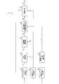
- FIG. 4 It is a block diagram which shows the structure of the outline line width setting apparatus which concerns on one Embodiment of this invention. It is a flowchart which shows the flow of the outline width setting method which concerns on one Embodiment of this invention. It is a schematic diagram which shows the operation example of the outline line width setting apparatus shown in FIG. It is a block diagram which shows the structure of the television receiver provided with the OSD drawing part which operate
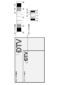
- (A) is a schematic diagram showing an example of a screen when displaying two screens
- (b) is a schematic diagram showing an example of a screen when displaying PinP (PicturePin Picture).
- (A) is a flowchart which shows the flow of the outline width setting method which concerns on one Embodiment of this invention
- (b) is the screen size ratio calculation in the outline width setting method which concerns on one Embodiment of this invention.
- It is a flowchart which shows a flow.
- FIG. 4 It is a schematic diagram which shows the character displayed on a display using a prior art. It is an external view which shows the structural example of the television receiver shown in FIG. 4, (a) is an external view of the display connected to the television receiver shown in FIG. 4, and the said television receiver, b) is an external view of a television receiver including the television receiver and the display shown in FIG. 4, and (c) is a connection to the television receiver shown in (b) and the television receiver.
- the contour line width setting device is a device for setting the contour line width of characters to be displayed on a display to a value corresponding to the size of the display.
- a television broadcast receiver (Hereinafter referred to as “television receiver”).
- the contour line width setting device is a contour line of characters to be OSD-displayed on a display built in or connected to the television receiver (which may be wired connection or wireless connection).
- the outline width of a character refers to the line width of the outline attached
- FIG. 1 is a block diagram showing the configuration of the contour line width setting device 1.
- the contour line width setting device 1 includes a display size acquisition unit 11, a reference size acquisition unit 12, a ratio calculation unit 13, a line width calculation unit 14, and an integerization unit 15. Yes.
- the display size acquisition unit 11 is a configuration for acquiring the target display size X.
- the “target display size” refers to the physical size of the display on which characters having the contour line width set by the contour line width setting device 1 are displayed.
- the target display size X acquired by the display size acquisition unit 11 is supplied to a ratio calculation unit 13 and an integerization unit 15 described later.
- the target display size X is given as an integer value in units of inches, for example.
- the reference size acquisition unit 12 is a configuration for acquiring the reference display size Y and the reference contour line width V.
- the “reference display size” refers to a physical size of a display that is predetermined as a display to be used as a reference for the screen design.
- the “reference contour line width” refers to a logical size of a contour line that is predetermined as a contour line to be attached to characters displayed on the reference display.
- the reference display size Y acquired by the reference size acquisition unit 12 is supplied to a ratio calculation unit 13 and an integerization unit 15 described later, as shown in FIG.
- standard outline line width V which the reference
- the reference display size Y is given as an integer value in units of inches, for example, and the reference outline width V is given as an integer value in units of dots, for example.
- the ratio calculation unit 13 is a configuration for calculating the ratio Y / X of the reference display size Y to the target display size X.
- the calculation of the ratio Y / X by the ratio calculation unit 13 is realized, for example, by dividing the reference display size Y supplied from the reference size acquisition unit 12 by the target display size X supplied from the display size acquisition unit 11.
- the ratio Y / X calculated by the ratio calculation unit 13 is supplied to a line width calculation unit 14 to be described later, as shown in FIG.
- the ratio Y / X is given as a unitless decimal value (having a predetermined number of digits), for example.
- the contour line width W calculated by the line width calculation unit 14 is supplied to the integerization unit 15 as shown in FIG.
- the contour line width W is a logical size given as a decimal value (having a predetermined number of digits) in units of dots.
- the integer converting unit 15 is configured to obtain an outline line width W ′ that is an integer value by converting the outline line width W that is a decimal value into an integer.
- the integerization of the contour line width W by the integerization unit 15 is performed as follows, for example. That is, when the target display size X is larger than the size Y of the reference display, the integer converting unit 15 obtains the contour line width W ′ by discarding the decimal part of the contour line width W. On the other hand, when the target display size X is equal to or smaller than the size Y of the reference display, the integerizing unit 15 obtains the contour line width W ′ by rounding up the decimal part of the contour line width W.
- the contour line width W ′ of the character displayed on the target display can be set to a value that is substantially inversely proportional to the target display size X (inversely proportional to integer precision). it can.
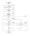
- FIG. 2 is a flowchart showing the flow of the contour line width setting method.
- the contour line width setting method includes a size acquisition step S11, a ratio calculation step S12, a line width calculation step S13, and an integer step S14, as shown in FIG.
- the size acquisition step S11 is a step of acquiring the target display size X, the reference display size Y, and the reference contour line width V. As described above, acquisition of the target display size X is executed by the display size acquisition unit 11, and acquisition of the reference display size Y and the reference outline width V is executed by the reference size acquisition unit 12.
- the ratio calculation step S12 is a step of calculating the ratio Y / X from the target display size X and the reference display size Y acquired in the size acquisition step S11. As described above, the ratio Y / X is calculated by the ratio calculation unit 13.
- the line width calculation step S13 is a step of calculating the contour line width W from the reference contour line width V acquired in the size acquisition step S11 and the ratio Y / X calculated in the ratio calculation step S12. As described above, the calculation of the contour line width W is executed by the line width calculation unit 14.
- Integer conversion step S14 is a step of converting the contour line width W calculated in the line width calculation step S13 into an integer. As described above, the integer conversion of the contour line width W is performed by the integer conversion unit 15.
- the integer step S14 includes, for example, a determination step S141, a truncation step S142, and a round-up step S143.
- Determination step S141 is a step in which the target display size X and the reference display size Y are compared in size.
- the integer converting unit 15 executes a truncation step S142 described later.
- the integer converting unit 15 executes a rounding-up step S143 described later.
- the rounding-up step S143 is a step of obtaining the contour line width W ′ that is an integer value by rounding up the decimal part of the contour line width W.
- the contour line width W ′ of the character displayed on the target display can be set to a value that is substantially inversely proportional to the target display size X (inversely proportional to integer precision). it can.
- This contour line width setting method can be applied to a method of manufacturing a television receiver (a television receiver with a built-in display).
- the contour line width setting method uses the contour line width of characters to be OSD displayed on a display (hereinafter referred to as “built-in display”) incorporated in a television receiver to be manufactured, and the size of the built-in display. Used to set according to The contour line width set using this contour line width setting method is recorded on, for example, a recording medium (hereinafter referred to as “built-in recording medium”) built in a television receiver to be manufactured.
- the television receiver manufactured in this way refers to the contour line width that is set by using this contour line width setting method and recorded on the internal recording medium when OSD-displaying characters on the built-in display. Can do.
- the processing entity that executes each step constituting the contour line width setting method is a manufacturing apparatus that manufactures a television receiver. (Manufacturing apparatus provided with the contour line width setting device 1) or a manufacturer (operator) who manufactures a television receiver may be used.
- FIG. 3 is a schematic diagram illustrating an operation example of the contour line width setting apparatus 1.
- A1 indicates a region constituting a stroke
- A2 indicates a region constituting a contour
- A3 indicates a region constituting a background.
- This example of operation sets the outline width of a 48-dot character displayed on the display.
- the reference display size Y is 60 inches
- the target display size X is 46 inches and 90 inches.
- the reference contour width V that is, the contour width when displaying 48-dot characters on a 60-inch reference display is 2 dots.
- the rounding-up step S143 is executed in the integer step S14.
- the physical line width of the 3-dot outline displayed on the 46-inch target display is about 0.15 mm, and the physical line width of the 2-dot outline displayed on the 60-inch reference display (about 0.14 mm).
- the rounding step S142 is executed in the integer step S14.
- the physical line width of the 1-dot outline displayed on the 90-inch target display is about 0.10 mm, and the physical-line width of the 2-dot outline displayed on the 60-inch reference display (about 0.14 mm).
- the width (in dots) and the physical line width (in mm) of the outline are arranged as shown in the table below.
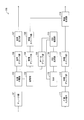
- FIG. 4 is a block diagram showing a configuration of the television receiver 100.
- the television receiver 100 includes a tuner unit 101, a demultiplexing unit 102, a channel selection unit 103, a video decoding unit 104, a video scaler unit 105, an audio decoding unit 106, and an audio output.
- the functions of the blocks other than the OSD drawing unit 110 are the same as those of the conventional receiver, and the description thereof is omitted here.
- the television receiver 100 is a receiver that receives television broadcasts (digital terrestrial broadcast, BS broadcast, CS broadcast, etc.), and is used by connecting to an external display (not shown).
- the OSD drawing unit 110 sets the outline width of characters to be OSD-displayed on the external display connected to the television receiver 100 according to the size of the external display.
- the external display may be a wired connection to the television receiver 100 by HDMI (registered trademark) or the like, or may be wirelessly connected to the television receiver 100 by WiFi (registered trademark) or the like. There may be.
- the television receiver 100 When the external display is connected by wire, the television receiver 100 further includes a communication unit that generates an electric signal modulated with a video signal on which characters displayed in OSD are superimposed, and a communication unit that generates the electric signal. An output terminal for outputting an electric signal to the outside is added.
- the television receiver 100 when an external display is wirelessly connected, the television receiver 100 further includes a communication unit that generates an electric signal modulated with a video signal on which characters to be displayed on the OSD are superimposed, and a communication unit that generates the electric signal. And an antenna for converting the electrical signal into an electromagnetic wave.
- the television receiver 100 when a wired connection is established with an external display, the television receiver 100 has size information (the target display size X) indicating the size of the external display (target display size X) when the wired connection with the external display is established. EDID in the case of HDMI connection) is acquired from the external display, and the acquired size information is stored in the RAM 115.
- the television receiver 100 determines the size of the external display (target display) when wireless connection with the external display is established (when pairing is established). Size information indicating size X) is acquired from the external display, and the acquired size information is stored in the RAM 115.
- the reference display size Y and the reference contour line width V are stored in the RAM 115 in advance before shipment. Therefore, the OSD drawing unit 110 can read the target display size X, the reference display size Y, and the reference contour line width V from the RAM 115 at an arbitrary timing after the connection with the external display is established. .
- the OSD drawing unit 110 calculates the contour line width W ′ according to the flowchart shown in FIG. 2. At this time, in the size acquisition step S ⁇ b> 11, the OSD drawing unit 110 reads the target display size X, the reference display size Y, and the reference contour line width V from the RAM 115.
- the OSD drawing unit 110 When a character code is supplied from the OSD generation unit 109, the OSD drawing unit 110 reads a font corresponding to the character code from the RAM 115, and generates a character image to be superimposed on the video signal. At this time, the line width of the outline attached to the periphery of the stroke constituting the character included in the character image is set as the outline width W ′ set as described above. Thereby, even if the external display connected to the television receiver 100 is larger or smaller than the reference display, characters having an appropriate outline width are always displayed on the external display. Will be.
- the appearance of the television receiver 100 described here is as shown in FIG.
- the television receiver 100 illustrated in FIG. 15A is used together with the external display 200, and sets the outline width of characters according to the size of the external display 200.
- the television receiver 100 illustrated in FIG. 15A may be referred to as a “tuner unit” or the like.
- the structure which operates the OSD drawing part of the television receiver connected to a display (external display) as the outline line width setting apparatus 1 was demonstrated here, it is not limited to this. That is, a configuration in which the OSD drawing unit of a television receiver (that is, a television receiver) having a built-in display (built-in display) is operated as the contour line width setting device 1 may be adopted. In this case, a television receiver having a built-in display of any size does not change the function as the contour width setting device 1 of the OSD drawing unit, and incorporates characters having an appropriate contour width. Can be displayed on the display.
- the OSD drawing section can be set to the outline width regardless of the size of the television receiver having the built-in display. Characters having an appropriate contour line width can be displayed on the built-in display without changing a program for operating as the device 1.
- FIG. 300 is assigned to the television receiver.
- the television receiver including the OSD drawing unit functioning as the contour line width setting device 1 has been described.
- a device in which the contour line width setting device 1 can be mounted is not limited to the television receiver.
- the present invention can be applied even to an apparatus that does not have a function of receiving an image as long as it is an image output apparatus that outputs an image on which characters are superimposed.
- a playback device such as a DVD player or a BD player is an example of such a video output device.
- the outline width of the character to be superimposed on the output video is set according to the size of the display that is the output destination of the video.
- FIG. 15C An example of the appearance of the playback apparatus described here is shown in FIG. 15C, for example.
- the playback apparatus 400 illustrated in FIG. 15C is used in combination with the television receiver 300, and sets the outline width of characters according to the display size provided in the television receiver 300.
- the contour line width setting device sets the contour line width of the character displayed on the display to a value corresponding to both the size of the display and the size of the screen displayed in a reduced size on the display.
- the “screen size” refers to the logical size of the screen that is reduced and displayed on the display. For example, a pair of horizontal pixel number X1 and vertical pixel number Y1 (horizontal pixel number X1, vertical pixel number Y1). ).
- Examples of screens that are reduced and displayed on the display include (1) one screen in two-screen display, or (2) child screen in PinP (Picture-in-Picture) display.
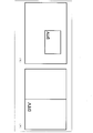
- FIG. 5 (a) is a front view of the display during two-screen display.
- the contour line width setting apparatus uses the contour line width of the character “DTV” displayed on the left screen reduced and displayed on the left side of the display, the physical size of the display, and the logic of the left screen. It will be set according to both sizes.
- FIG. 5B is a front view of the display during PinP display.
- the contour line width setting device uses the contour line width of the character “DTV” displayed on the sub-screen that is reduced and displayed on a part of the display, the physical size of the display, and the left screen. It is set according to both logical sizes.
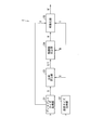
- FIG. 6 is a block diagram showing a configuration of the contour line width setting device 1 ′.
- symbol is attached and the description is abbreviate
- the contour line width setting device 1 ′ includes a screen size acquisition unit 16, a screen size ratio calculation unit 17, and a reduction in addition to the configuration of the contour line width setting device 1 according to the first embodiment. And a display line width calculation unit 18.
- the screen size acquisition unit 16 is a configuration for acquiring the size of a screen that is reduced and displayed on the display (hereinafter also referred to as “reduced screen”).
- the screen size acquisition unit 16 acquires a reduced screen size (X1, Y1) indicating the size of the reduced screen.
- the screen size acquisition unit 16 acquires the full screen size (X2, Y2) of the display.
- the reduced screen size (X1, Y1) and the full screen size (X2, Y2) acquired by the screen size acquisition unit 16 are supplied to a screen size ratio calculation unit 17 described later.
- the screen size ratio calculation unit 17 is a configuration for calculating a screen size ratio P indicating a ratio between the total screen size of the display and the reduced screen size.
- the calculation of the ratio P by the screen size ratio calculation unit 17 is executed by the following procedure, for example.
- the screen size ratio calculating unit 17 divides the horizontal pixel number X2 of the display by the quotient X2 / X1 divided by the horizontal pixel number X1 of the reduced screen and the vertical pixel number Y2 of the display by the vertical pixel number Y1 of the reduced screen.
- the quotient Y2 / Y1 is calculated.
- the screen size ratio calculation unit 17 compares the quotient X2 / X1 with the quotient Y2 / Y1, and sets X2 / X1 as the screen size ratio P if (X2 / X1)> (Y2 / Y1). . On the other hand, the screen size ratio calculation unit 17 sets Y2 / Y1 as the screen size ratio P when (X2 / X1) ⁇ (Y2 / Y1). The screen size ratio P calculated by the screen size ratio calculation unit 17 is supplied to the reduced display line width calculation unit 18.
- the screen size ratio P is given as, for example, a unitless decimal value (having a predetermined number of digits).
- the contour line width W calculated by the line width calculation unit 14 is supplied to the reduced display line width calculation unit 18 as shown in FIG.
- the contour line width W1 calculated by the reduced display line width calculation unit 18 is supplied to the integerization unit 15 as shown in FIG.
- the contour line width W1 is a logical size given as a decimal value (having a predetermined number of digits) in units of dots.
- the integerization unit 15 is configured to obtain the contour line width W 'that is an integer value by converting the contour line width W1 that is a decimal value into an integer.
- the integerization of the contour line width W by the integerization unit 15 is performed as follows, for example. That is, when the target display size X is larger than the size Y of the reference display, the integer converting unit 15 obtains the contour line width W ′ by discarding the decimal part of the contour line width W1. On the other hand, when the target display size X is equal to or smaller than the size Y of the reference display, the integer converting unit 15 obtains the contour line width W ′ by rounding up the decimal part of the contour line width W1.
- the contour line width W ′ of the character displayed on the reduced screen is set to the target display size X and the size of the reduced screen displayed on the display (X1 or Y1). ) Can be set to a value that is substantially inversely proportional to both (inversely proportional to integer precision).
- the contour line width setting method includes a size acquisition step S21, a ratio calculation step S22, a line width calculation step S23, a reduced display line width calculation step S25, and an integer step. S24.
- the size acquisition step S21 is a step of acquiring the target display size X, the reference display size Y, and the reference contour line width V. As described above, acquisition of the target display size X is executed by the display size acquisition unit 21, and acquisition of the reference display size Y and the reference outline width V is executed by the reference size acquisition unit 12.
- the ratio calculation step S22 is a step of calculating the ratio Y / X from the target display size X and the reference display size Y acquired in the size acquisition step S21. As described above, the ratio Y / X is calculated by the ratio calculation unit 23.
- the line width calculation step S23 is a step of calculating the contour line width W from the reference contour line width V acquired in the size acquisition step S21 and the ratio Y / X calculated in the ratio calculation step S22. As described above, the calculation of the contour line width W is executed by the line width calculation unit 14.
- Integer conversion step S24 is a step of converting the contour line width W1 calculated in the reduced display line width calculation step S25 into an integer. As described above, the integer conversion of the contour line width W1 is performed by the integer conversion unit 15.
- the integer step S24 includes, for example, a determination step S241, a truncation step S242, and a round-up step S243.
- Determination step S241 is a step of comparing the size of the target display size X and the reference display size Y.
- the integer converting unit 15 executes a truncation step S242 described later.
- the integer converting unit 15 executes a rounding-up step S243 described later.
- the truncation step S242 is a step of obtaining the contour line width W ′ that is an integer value by discarding the decimal part of the contour line width W1.
- W ′ n is obtained in the truncation step S242.
- the rounding-up step S243 is a step of obtaining the contour line width W ′ that is an integer value by rounding up the decimal part of the contour line width W1.
- the contour line width W ′ of the character displayed on the reduced screen is approximately inversely proportional to both the target display size X and the size (X1 or Y1) of the reduced screen. Can be set to a value that is inversely proportional to integer precision.
- FIG. 7B is a flowchart showing a flow of calculating the screen size ratio P in the contour line width setting method.
- the screen size acquisition step S31 is a step for acquiring the size of the screen displayed on the display. As described above, the screen size is acquired by the screen size acquisition unit 16. The screen size acquisition unit 16 acquires the full screen size and the reduced screen size in the screen size acquisition step S31. The full screen size and the reduced image size acquired in the screen size acquisition step S31 are supplied to the screen size ratio calculation unit 17.
- Steps S32 to S34 are steps for calculating a screen size ratio P indicating the ratio of the reduced screen size to the total screen size of the display. As described above, the screen size ratio calculation unit 17 executes steps S32 to S34.
- the screen size ratio calculation unit 17 obtains the quotient 1920 / X1 obtained by dividing the display horizontal pixel number 1920 by the horizontal pixel number X1 of the reduced screen and the vertical pixel number 1080 of the display to the vertical size of the reduced screen.
- the quotient 1080 / Y1 divided by the number of pixels Y1 is calculated.
- the screen size ratio calculation unit 17 compares the quotient 1920 / X1 with the quotient 1080 / Y1. If (1920 / X1)> (1080 / Y1), the screen size ratio calculation unit 17 sets 1920 / X1 as the screen size ratio P (setting step S33). On the other hand, when (1920 / X1) ⁇ (1080 / Y1), the screen size ratio calculation unit 17 sets 1080 / Y1 as the screen size ratio P (setting step S34).
- the contour line width setting apparatus 1 ′ can calculate the screen size ratio P.
- this contour line width setting method can be applied to a method of manufacturing a television receiver, similarly to the contour line width setting method according to the first embodiment.
- the contour line width setting method uses the contour line width of characters to be OSD displayed on the built-in display of the television receiver to be manufactured, the size of the built-in display, and the size of the reduced screen displayed on the built-in display. It is used to set according to both.
- the contour line width set using this contour line width setting method is recorded, for example, on a built-in recording medium of a television receiver to be manufactured.
- the television receiver manufactured in this way refers to the contour line width that is set by using this contour line width setting method and recorded on the internal recording medium when OSD-displaying characters on the built-in display. Can do.
- the processing entity that executes each step constituting the contour line width setting method is a manufacturing apparatus that manufactures a television receiver. (Manufacturing apparatus provided with the contour line width setting device 1 ′) or a manufacturer (operator) who manufactures a television receiver.
- FIG. 4 is a block diagram showing a configuration of the television receiver 100.
- the functions of the blocks other than the OSD drawing unit 110 are the same as the functions described in the first embodiment, and thus description thereof is omitted here.
- the television receiver 100 is a receiver that receives a television broadcast, and is used by connecting to an external display (not shown).
- the OSD drawing unit 110 reduces the outline width of characters to be OSD-displayed on an external display connected to the television receiver 100, the size of the external display, and the reduction displayed on the external display. Set according to both the screen size.
- the external display may be a wired connection to the television receiver 100 by HDMI or the like, or may be wirelessly connected to the television receiver 100 by WiFi or the like.
- the television receiver 100 further includes a communication unit that generates an electric signal modulated with a video signal on which characters displayed in OSD are superimposed, and a communication unit that generates the electric signal.
- An output terminal for outputting an electric signal to the outside is added.
- the television receiver 100 further includes a communication unit that generates an electric signal modulated with a video signal on which characters to be displayed on the OSD are superimposed, and a communication unit that generates the electric signal.
- an antenna for converting the electrical signal into an electromagnetic wave.
- the television receiver 100 when a wired connection is established with an external display, the television receiver 100 has size information (the target display size X) indicating the size of the external display (target display size X) when the wired connection with the external display is established. EDID for HDMI connection) and full screen size information indicating the full screen size (X2, Y2) which is the logical size of the external display is acquired from the external display, and the acquired size information and full screen size information Is stored in the RAM 115.
- the television receiver 100 determines the size of the external display (target display) when wireless connection with the external display is established (when pairing is established). Size information indicating size X) and full screen size information of the external display are acquired from the external display, and the acquired size information and full screen size information are stored in the RAM 115.
- the reference display size Y and the reference contour line width V are stored in the RAM 115 in advance before shipment. Therefore, the OSD drawing unit 110 establishes the target display size X, the reference display size Y, the full screen size (X2, Y2), and the reference contour line width V at any timing after the connection with the external display is established. Can be read from the RAM 115.
- the video scalers 105 and 113 reduce the size of the screen displayed on the external display.
- the reduced screen size information indicating the reduced screen size (X1, Y1) of the screen reduced by the video scalers 105 and 113 is stored in the RAM 115. Therefore, the OSD drawing unit 110 can read the reduced screen size (X1, Y1) from the RAM 115 at an arbitrary timing after the external display starts two-screen display or after starting PinP display. .
- the OSD drawing unit 110 sets the screen size ratio P by using, for example, a notification from the video scaler unit 105 or 113 as a trigger to receive a notification to start two-screen display or a notification to start PinP display. It is good also as a structure to calculate.
- the OSD drawing unit 110 calculates the contour line width W ′ according to the flowchart shown in FIG. At this time, in the size acquisition step S ⁇ b> 21, the OSD drawing unit 110 reads the target display size X, the reference display size Y, and the reference contour line width V from the RAM 115. In the screen size acquisition step S31, the OSD drawing unit 110 reads the full screen size (X2, Y2) and the reduced screen size (X1, Y1) from the RAM 115.
- the OSD drawing unit 110 When a character code is supplied from the OSD generation unit 109, the OSD drawing unit 110 reads a font corresponding to the character code from the RAM 115, and generates a character image to be superimposed on the video signal. At this time, the line width of the outline attached to the periphery of the stroke constituting the character included in the character image is set as the outline width W ′ set as described above. Thereby, even if the external display connected to the television receiver 100 is larger or smaller than the reference display, it is always appropriate according to the size of the reduced screen displayed on the external display. A character having a wide contour line width is displayed on the external display.
- the structure which operates the OSD drawing part of the television receiver connected to an external display as the outline line width setting apparatus 1 ' was demonstrated here, it is not limited to this. That is, a configuration in which the OSD drawing unit of a television receiver (that is, a television receiver) having a built-in display (built-in display) is operated as the contour line width setting device 1 ′ may be employed. In this case, a television receiver having a built-in display of any size does not change the function as the contour line width setting device 1 ′ of the OSD drawing unit, and the character having an appropriate contour line width can be obtained. Can be displayed on the built-in display.
- the OSD rendering unit when the function is implemented as software as the contour line width setting device 1 ′ of the OSD rendering unit, the OSD rendering unit is configured to have the contour line width regardless of the size of the television receiver including the built-in display. Characters having an appropriate contour line width can be displayed on the built-in display without changing the program for operating as the setting device 1 ′.
- the television receiver including the OSD drawing unit functioning as the contour line width setting device 1 ′ has been described.
- the apparatus on which the contour line width setting device 1 ′ can be mounted is limited to the television receiver.
- the present invention can be applied even to an apparatus that does not have a function of receiving an image as long as it is an image output apparatus that outputs an image on which characters are superimposed.
- a playback device such as a DVD player or a BD player is an example of such a video output device.
- the outline width of the character to be superimposed on the video to be output is set according to both the size of the display serving as the video output destination and the size of the reduced screen displayed on the display.
- the contour gradation number setting device sets the number of gradations of the contour line attached to the character displayed on the display (hereinafter also referred to as “contour gradation number”) according to the size of the display.
- the contour gradation number setting device is a contour of characters to be OSD-displayed on a display built in or connected to the television receiver (may be wired connection or wireless connection). The number of gradations is set according to the size of the display.
- FIG. 8 is a block diagram showing the configuration of the contour gradation number setting device 2.
- the contour gradation number setting device 2 includes a display size acquisition unit 21, a reference size acquisition unit 22, a ratio calculation unit 23, a gradation number calculation unit 24, and an integerization unit 25. I have.
- the display size acquisition unit 21 is a configuration for acquiring the target display size X.
- the “target display size” refers to the physical size of the display on which characters having the contour gradation number set by the contour gradation number setting device 2 are displayed.
- the target display size X acquired by the display size acquisition unit 11 is supplied to a ratio calculation unit 23 and an integerization unit 25, which will be described later, as shown in FIG. Note that the target display size X is given as an integer value in units of inches, for example.
- the reference size acquisition unit 22 is configured to acquire the reference display size Y and the reference contour gradation number M.
- the “reference display size” refers to a physical size of a display that is predetermined as a display used as a reference for the screen design.
- the “reference contour gradation number” refers to a gradation number predetermined as the gradation number of the contour line attached to the character displayed on the reference display.
- the reference display size Y acquired by the reference size acquisition unit 22 is supplied to a ratio calculation unit 23 and an integerization unit 25, which will be described later, as shown in FIG.
- the reference contour gradation number M acquired by the reference size acquisition unit 22 is supplied to a gradation number calculation unit 24 described later, as shown in FIG.
- the reference display size Y is given as, for example, an integer value in units of inches
- the reference contour gradation number M is given as, for example, a unitless integer value.
- the ratio calculation unit 23 is a configuration for calculating the ratio X / Y of the target display size X with respect to the reference display size Y.
- the calculation of the ratio X / Y by the ratio calculation unit 23 is realized, for example, by dividing the target display size X supplied from the display size acquisition unit 21 by the reference display size Y supplied from the reference size acquisition unit 22.
- the ratio X / Y calculated by the ratio calculation unit 13 is supplied to a gradation number calculation unit 24 described later, as shown in FIG.
- the ratio X / Y is given, for example, as a unitless decimal value (having a predetermined number of digits).
- the contour gradation number N calculated by the gradation number calculation unit 24 is supplied to the integerization unit 25 as shown in FIG. Note that the contour gradation number N is given as a unit-less decimal value (having a predetermined number of digits).
- the integerizing unit 25 is configured to obtain the contour gradation number N ′ that is an integer value by converting the contour gradation number N that is a decimal value into an integer.
- the integer conversion of the contour gradation number N by the integer converting unit 25 is performed as follows, for example. That is, when the target display size X is larger than the size Y of the reference display, the integer converting unit 25 obtains the contour gradation number N ′ by rounding up the decimal part of the contour gradation number N. On the other hand, when the target display size X is equal to or smaller than the size Y of the reference display, the integer converting unit 25 obtains the contour gradation number N ′ by discarding the decimal part of the contour gradation number N.
- the contour gradation number N ′ of the character displayed on the target display is set to a value substantially proportional to the target display size X (proportional to integer precision). be able to.
- FIG. 9 is a flowchart showing a flow of the contour gradation number setting method.
- the contour gradation number setting method includes a size acquisition step S41, a ratio calculation step S42, a gradation number calculation step S43, and an integerization step S44.
- the size acquisition step S41 is a step of acquiring the target display size X, the reference display size Y, and the reference contour gradation number M. As described above, acquisition of the target display size X is executed by the display size acquisition unit 21, and acquisition of the reference display size Y and the reference contour gradation number M is executed by the reference size acquisition unit 22.
- the ratio calculation step S42 is a step of calculating the ratio X / Y from the target display size X and the reference display size Y acquired in the size acquisition step S41. As described above, the ratio X / Y is calculated by the ratio calculation unit 23.
- the integer conversion step S44 is a step of converting the contour gradation number N calculated in the gradation number calculation step S43 into an integer. As described above, the integer gradation number N is converted into an integer by the integer converting unit 25.
- the integer step S44 includes, for example, a determination step S441, a round-up step S442, and a cutoff step S443.
- Determination step S441 is a step of comparing the size of the target display size X and the reference display size Y.
- the integer converting unit 25 executes a round-up step S442 described later.
- the integer converting unit 25 executes a truncation step S443 described later.
- the rounding-up step S442 is a step of obtaining the contour gradation number N ′ that is an integer value by rounding up the decimal part of the contour gradation number N.
- N ′ n + 1 is obtained in the round-up step S442.
- the contour gradation number N ′ of the character displayed on the target display is set to a value substantially proportional to the target display size X (proportional to integer precision). be able to.
- this contour gradation number setting method can be applied to a method of manufacturing a television receiver (a television receiver with a built-in display).
- the contour gradation number setting method uses the contour gradation number of characters to be OSD displayed on a display (hereinafter referred to as “built-in display”) built in a television receiver to be manufactured. It is used to set according to the size.
- the contour gradation number set using the contour gradation number setting method is recorded on, for example, a recording medium (hereinafter referred to as “built-in recording medium”) incorporated in a television receiver to be manufactured. .
- the television receiver manufactured as described above is set by using the contour gradation number setting method when characters are OSD-displayed on the built-in display, and the contour gradation number recorded on the built-in recording medium is referred to. can do.
- a processing entity that executes each step constituting the contour gradation number setting method manufactures and manufactures the television receiver. It may be a manufacturing device (a manufacturing device provided with the contour gradation number setting device 2) or a manufacturer (operator) who manufactures a television receiver.
- FIG. 10 is a schematic diagram illustrating an operation example of the contour gradation number setting device 2.
- A1 indicates a region that constitutes a stroke
- A2 indicates a region that constitutes a contour line
- A3 indicates a region that constitutes a background.
- This example of operation sets the number of contour gradations of 48-dot characters displayed on the display.
- the reference display size Y is 60 inches
- the target display size X is 46 inches and 90 inches.
- the width of the contour line attached to the character displayed on the 60-inch reference display is 6 dots
- the number of contour gradations (reference gradation number M) is 4 gradations.
- the physical line width of the 6-dot outline displayed on the 46-inch target display is about 0.3 mm, and the physical line width of the 6-dot outline displayed on the 60-inch reference display is about 0.4 mm. It becomes. Therefore, the gradation density (number of gradations per unit length) of the contour line displayed on the 46-inch target display is 10 gradations / mm, and the gradation density of the contour line displayed on the 60-inch reference display (10 gradation / mm).
- the contour gradation number setting device 2 calculates (1) X / Y ⁇ 1.5 in the ratio calculation step S2, and (2) proceeds to the gradation number calculation step S43.
- the rounding-up step S442 is executed in the integerizing step S4.
- the physical line width of the 6-dot outline displayed on the 90-inch target display is about 0.6 mm, and the physical line width of the 6-dot outline displayed on the 60-inch reference display is about 0.4 mm. It becomes. Therefore, the gradation density (number of gradations per unit length) of the contour line displayed on the 90-inch target display is 10 gradations / mm, and the gradation density of the contour line displayed on the 60-inch reference display (10 gradation / mm).
- Contour line width (dot unit), contour physical line width (mm unit), contour floor in 46-inch display (target display), 60-inch display (reference display), and 90-inch display (target display)
- the key number and the gradation number density (the gradation number per 1 mm) are arranged as shown in the table below.
- FIG. 4 is a block diagram showing a configuration of the television receiver 100.
- the television receiver 100 includes a tuner unit 101, a demultiplexing unit 102, a channel selection unit 103, a video decoding unit 104, a video scaler unit 105, an audio decoding unit 106, and an audio output.
- the functions of the blocks other than the OSD drawing unit 110 are the same as those of the conventional receiver, and the description thereof is omitted here.
- the television receiver 100 is a receiver that receives television broadcasts (digital terrestrial broadcast, BS broadcast, CS broadcast, etc.), and is used by connecting to an external display (not shown).
- the OSD drawing unit 110 sets the number of contour gradations of characters to be OSD displayed on an external display connected to the television receiver 100 according to the size of the external display.
- the external display may be a wired connection to the television receiver 100 by HDMI (registered trademark) or the like, or may be wirelessly connected to the television receiver 100 by WiFi (registered trademark) or the like. There may be.
- the television receiver 100 When the external display is connected by wire, the television receiver 100 further includes a communication unit that generates an electric signal modulated with a video signal on which characters displayed in OSD are superimposed, and a communication unit that generates the electric signal. An output terminal for outputting an electric signal to the outside is added.
- the television receiver 100 when an external display is wirelessly connected, the television receiver 100 further includes a communication unit that generates an electric signal modulated with a video signal on which characters to be displayed on the OSD are superimposed, and a communication unit that generates the electric signal. And an antenna for converting the electrical signal into an electromagnetic wave.
- the television receiver 100 when a wired connection is established with an external display, the television receiver 100 has size information (the target display size X) indicating the size of the external display (target display size X) when the wired connection with the external display is established. EDID in the case of HDMI connection) is acquired from the external display, and the acquired size information is stored in the RAM 115.
- the television receiver 100 determines the size of the external display (target display) when wireless connection with the external display is established (when pairing is established). Size information indicating size X) is acquired from the external display, and the acquired size information is stored in the RAM 115.
- the reference display size Y and the reference contour gradation number M are stored in the RAM 115 in advance before shipment. Therefore, the OSD drawing unit 110 can read the target display size X, the reference display size Y, and the reference contour gradation number M from the RAM 115 at an arbitrary timing after the connection with the external display is established. is there.
- the OSD drawing unit 110 calculates the contour gradation number N ′ according to the flowchart shown in FIG. 9. At this time, in the size acquisition step S41, the OSD drawing unit 110 reads the target display size X, the reference display size Y, and the reference contour gradation number M from the RAM 115.
- the OSD drawing unit 110 When a character code is supplied from the OSD generation unit 109, the OSD drawing unit 110 reads a font corresponding to the character code from the RAM 115, and generates a character image to be superimposed on the video signal. At this time, the number of gradations of the contour line attached to the periphery of the stroke constituting the character included in the character image is set to the contour gradation number N ′ set as described above. Thereby, even if the external display connected to the television receiver 100 is larger or smaller than the reference display, characters having an appropriate contour gradation number are always displayed on the external display. Will be.
- the structure which operates the OSD drawing part of the television receiver connected to a display (external display) as the outline gradation number setting apparatus 2 was demonstrated here, it is not limited to this. That is, a configuration in which the OSD drawing unit of a television receiver (that is, a television receiver) having a built-in display (built-in display) is operated as the contour gradation number setting device 2 may be adopted. In this case, even if the television receiver has a built-in display of any size, a character having an appropriate contour gradation number without changing the function as the contour gradation number setting device 2 of the OSD drawing unit. Can be displayed on the built-in display.
- the OSD drawing unit when the function as the contour gradation number setting device 2 of the OSD drawing unit is realized as software, the OSD drawing unit can be used as the contour gradation in any television receiver having a built-in display of any size. Characters having an appropriate contour gradation number can be displayed on the built-in display without changing the program for operating as the number setting device 2.
- the television receiver including the OSD drawing unit functioning as the contour gradation number setting device 2 has been described.
- devices that can be equipped with the contour gradation number setting device 2 are limited to the television receiver.
- the present invention can be applied even to an apparatus that does not have a function of receiving an image as long as it is an image output apparatus that outputs an image on which characters are superimposed.
- a playback device such as a DVD player or a BD player is an example of such a video output device.
- the number of contour gradations of characters to be superimposed on the video to be output is set according to the size of the display that is the output destination of the video.
- the contour gradation number setting device specifies the number of gradations of a contour line (hereinafter also referred to as “contour gradation number”) attached to a character displayed on the display, the size of the display, and the display.
- This is a device for setting a value corresponding to both the size of the screen to be reduced and displayed, and can be mounted on, for example, a television receiver.
- screen size refers to the logical size of the screen that is reduced and displayed on the display. For example, a pair of horizontal pixels X1 and vertical pixels Y1 (horizontal pixels). It is represented by the number X1 and the vertical pixel number Y1).
- FIG. 5 (a) is a front view of the display during two-screen display.
- the contour gradation number setting device uses the contour gradation number attached to the character “DTV” displayed on the left screen reduced and displayed on the left side of the display, the physical size of the display, and the left It is set according to both the logical size of the screen.
- FIG. 5B is a front view of the display during PinP display.
- the contour gradation number setting device uses the contour gradation number attached to the character “DTV” displayed on the sub-screen that is reduced and displayed on a part of the display, the physical size of the display, and the It is set according to both the logical size of the left screen.
- FIG. 11 is a block diagram showing the configuration of the contour gradation number setting device 2 ′.
- symbol is attached and the description is abbreviate
- the contour gradation number setting device 2 ′ has a configuration similar to that of the contour gradation number setting device 2 according to the third embodiment, a screen size acquisition unit 26, and a screen size ratio calculation unit. 27 and a reduced display gradation number calculation unit 28.
- the screen size acquisition unit 26 is a configuration for acquiring the size of a screen that is reduced and displayed on the display (hereinafter also referred to as “reduced screen”).
- the screen size acquisition unit 26 acquires a reduced screen size (X1, Y1) indicating the size of the reduced screen.
- the screen size acquisition unit 26 acquires the full screen size (X2, Y2) of the display.
- the reduced screen size (X1, Y1) and the full screen size (X2, Y2) acquired by the screen size acquisition unit 26 are supplied to a screen size ratio calculation unit 27 described later.
- the screen size ratio calculation unit 27 is a configuration for calculating a screen size ratio P indicating a ratio between the total screen size of the display and the reduced screen size.
- the calculation of the ratio P by the screen size ratio calculation unit 27 is executed by the following procedure, for example.
- the screen size ratio calculating unit 27 divides the horizontal pixel number X1 of the reduced screen by the quotient X1 / X2 divided by the horizontal pixel number X2 of the display and the vertical pixel number Y1 of the reduced screen by the vertical pixel number Y2 of the display.
- the quotients Y1 / Y2 are calculated.
- the screen size ratio calculation unit 27 compares the quotient X1 / X2 with the quotient Y1 / Y2, and sets X1 / X2 as the screen size ratio P when (X1 / X2) ⁇ (Y1 / Y2). To do. On the other hand, the screen size ratio calculation unit 27 sets Y1 / Y2 as the screen size ratio P when (X1 / X2) ⁇ (Y1 / Y2). The screen size ratio P calculated by the screen size ratio calculation unit 27 is supplied to the reduced display gradation number calculation unit 28.
- the screen size ratio P is given as, for example, a unitless decimal value (having a predetermined number of digits).
- the contour gradation number N calculated by the gradation number calculation unit 24 is supplied to the reduced display gradation number calculation unit 28 as shown in FIG.
- the contour gradation number N1 calculated by the reduced display gradation number calculation unit 28 is supplied to the integerization unit 25 as shown in FIG.
- the contour gradation number N1 is given as a unitless decimal value (having a predetermined number of digits).
- the integer converting unit 25 is configured to obtain the contour gradation number N ′ that is an integer value by converting the contour gradation number N1 that is a decimal value into an integer.
- the integer conversion unit 25 converts the contour gradation number N1 into an integer, for example, as follows. That is, when the target display size X is larger than the size Y of the reference display, the integer converting unit 25 obtains the contour gradation number N ′ by rounding up the decimal part of the contour gradation number N1. On the other hand, when the target display size X is equal to or smaller than the size Y of the reference display, the integer converting unit 25 obtains the contour gradation number N ′ by discarding the decimal part of the contour gradation number N1.
- the contour gradation number N ′ of characters displayed on the target display is set to both the target display size X and the reduced screen size (X1 or Y1). It can be set to a value that is approximately proportional (proportional to integer precision).
- FIG. (A) of FIG. 12 is a flowchart which shows the flow of this outline gradation number setting method.
- the contour gradation number setting method includes a size acquisition step S51, a ratio calculation step S52, a gradation number calculation step S53, a reduced display gradation number calculation step S55, and an integerization step S54. Including.
- the size acquisition step S51 is a step of acquiring the target display size X, the reference display size Y, and the reference contour gradation number M. As described above, acquisition of the target display size X is executed by the display size acquisition unit 21, and acquisition of the reference display size Y and the reference contour gradation number M is executed by the reference size acquisition unit 22.
- the ratio calculation step S52 is a step of calculating the ratio X / Y from the target display size X and the reference display size Y acquired in the size acquisition step S51. As described above, the ratio X / Y is calculated by the ratio calculation unit 23.
- the calculation of the contour line width W1 is executed by the reduced display gradation number calculation unit 28.
- a method for calculating the screen size ratio P will be described later with reference to another drawing.
- the integer step S54 is a step for converting the contour gradation number N1 calculated in the reduced display gradation number calculation step S55 into an integer. As described above, the integer gradation number N1 is converted into an integer by the integer converting unit 25.
- the integer step S54 includes, for example, a determination step S541, a round-up step S542, and a cutoff step S543.
- Determination step S541 is a step of comparing the size of the target display size X and the reference display size Y.
- the integer converting unit 25 executes a round-up step S542 described later.
- the integer converting unit 25 executes a truncation step S543 described later.
- the rounding-up step S542 is a step of obtaining the contour gradation number N ′ which is an integer value by rounding up the decimal part of the contour gradation number N1.
- N ′ n + 1 is obtained in the round-up step S542.
- the contour gradation number N ′ of characters displayed on the target display is approximately proportional to the target display size X and the reduced screen size (X1 or Y1). Can be set to a value (proportional to integer precision).
- FIG. 12B is a flowchart showing a flow of calculating the screen size ratio P in the contour line width setting method.
- the screen size acquisition step S61 is a step for acquiring the size of the screen displayed on the display. As described above, the screen size is acquired by the screen size acquisition unit 26.
- the screen size acquisition unit 26 acquires the full screen size and the reduced screen size in the screen size acquisition step S61.
- the full screen size and the reduced image size acquired in the screen size acquisition step S61 are supplied to the screen size ratio calculation unit 27.
- Steps S62 to S64 are steps for calculating a screen size ratio P indicating the ratio of the reduced screen size to the total screen size of the display. As described above, the screen size ratio calculation unit 27 executes steps S62 to S64.
- the screen size ratio calculating unit 27 calculates the quotient X1 / 1920 obtained by dividing the horizontal pixel number X1 of the reduced screen by the horizontal pixel number 1920 of the display and the vertical pixel number Y1 of the reduced screen as the vertical display.
- the quotient Y1 / 1080 divided by the number of pixels 1080 is calculated.
- the screen size ratio calculation unit 27 compares the quotient X1 / 1920 with the quotient Y1 / 1080. If (X1 / 1920) ⁇ (Y1 / 1080), the screen size ratio calculation unit 27 sets X1 / 1920 as the screen size ratio P (setting step S63). On the other hand, when (X1 / 1920) ⁇ (Y1 / 1080), the screen size ratio calculation unit 17 sets Y1 / 1080 as the screen size ratio P (setting step S64).
- this contour gradation number setting method can be applied to a method of manufacturing a television receiver, similarly to the contour gradation number setting method according to the third embodiment.
- this contour gradation number setting method is to reduce the contour gradation number of characters to be OSD displayed on the built-in display of the television receiver to be manufactured, the size of the built-in display, and the reduction displayed on the built-in display. Used to set according to both the screen size.
- the contour gradation number set by using this contour gradation number setting method is recorded, for example, on a built-in recording medium of a television receiver to be manufactured.
- the television receiver manufactured as described above is set by using the contour gradation number setting method when characters are OSD-displayed on the built-in display, and the contour gradation number recorded on the built-in recording medium is referred to. can do.
- a processing entity that executes each step constituting the contour gradation number setting method manufactures and manufactures the television receiver. It may be a manufacturing device (a manufacturing device provided with the contour gradation number setting device 2 ′) or a manufacturer (operator) who manufactures a television receiver.
- FIG. 4 is a block diagram showing a configuration of the television receiver 100.
- the television receiver 100 differs from the television receiver 100 described in the second embodiment in that the OSD drawing unit 110 functions as the contour gradation number setting device 2 ′. That is, the OSD drawing unit 110 displays the contour gradation number of characters to be OSD displayed on the external display connected to the television receiver 100, the size of the external display, and the reduced screen displayed on the external display. Set according to both size.
- the OSD drawing unit 110 calculates the contour gradation number N ′ according to the flowchart shown in FIG. At this time, in the size acquisition step S51, the OSD drawing unit 110 reads the target display size X, the reference display size Y, and the reference contour gradation number M (stored in the RAM 115 in advance before shipment) from the RAM 115. become. In the screen size acquisition step S61, the OSD drawing unit 110 reads the full screen size (X2, Y2) and the reduced screen size (X1, Y1) from the RAM 115.
- the OSD drawing unit 110 When a character code is supplied from the OSD generation unit 109, the OSD drawing unit 110 reads a font corresponding to the character code from the RAM 115, and generates a character image to be superimposed on the video signal. At this time, the number of gradations of the contour line attached to the periphery of the stroke constituting the character included in the character image is set to the contour gradation number N ′ set as described above. Thereby, even if the external display connected to the television receiver 100 is larger or smaller than the reference display, it is always appropriate according to the size of the reduced screen displayed on the external display. A character having a large number of contour gradations is displayed on the external display.
- each block of the contour line width setting device 1, the contour line width setting device 1 ′, the contour gradation number setting device 2, and the contour gradation number setting device 2 ′ is formed on an integrated circuit (IC chip). It may be realized by hardware using a logic circuit that has been configured, or may be realized by software using a CPU (Central Processing Unit).
- IC chip integrated circuit
- the contour line width setting device 1, the contour line width setting device 1 ′, the contour gradation number setting device 2, and the contour gradation number setting device 2 ′ execute instructions of a program that realizes each function.
- a CPU, a ROM (Read Only Memory) storing the program, a RAM (Random Access Memory) expanding the program, a storage device (recording medium) such as a memory storing the program and various data, and the like are provided.
- An object of the present invention is an outline line width setting device 1, an outline line width setting device 1 ′, an outline gradation number setting device 2, and an outline gradation number setting device 2 ′, which are software for realizing the functions described above.
- a recording medium on which the program code (execution format program, intermediate code program, source program) of the control program is recorded so as to be readable by a computer is recorded on the contour line width setting device 1, contour line width setting device 1 ', contour gradation number
- Examples of the recording medium include non-transitory tangible media, such as magnetic tapes and cassette tapes, magnetic disks such as floppy (registered trademark) disks / hard disks, and CD-ROM / MO.
- Discs including optical disks such as / MD / DVD / CD-R, cards such as IC cards (including memory cards) / optical cards, and semiconductor memories such as mask ROM / EPROM / EEPROM (registered trademark) / flash ROM
- logic circuits such as PLD (Programmable logic device) and FPGA (Field Programmable Gate array) can be used.
- the contour line width setting device 1, the contour line width setting device 1 ′, the contour gradation number setting device 2 and the contour gradation number setting device 2 ′ are configured to be connectable to a communication network, and the program code is communicated. You may supply via a network.
- the communication network is not particularly limited as long as it can transmit the program code.
- the Internet, intranet, extranet, LAN, ISDN, VAN, CATV communication network, virtual private network (Virtual Private Network), telephone line network, mobile communication network, satellite communication network, etc. can be used.
- the transmission medium constituting the communication network may be any medium that can transmit the program code, and is not limited to a specific configuration or type.
- wired lines such as IEEE 1394, USB, power line carrier, cable TV line, telephone line, ADSL (Asymmetric Digital Subscriber Line) line, infrared rays such as IrDA and remote control, Bluetooth (registered trademark), IEEE 802.11 wireless, HDR ( It can also be used by wireless such as High Data Rate (NFC), Near Field Communication (NFC), Digital Living Network Alliance (DLNA), mobile phone network, satellite line, and terrestrial digital network.
- the present invention can also be realized in the form of a computer data signal embedded in a carrier wave in which the program code is embodied by electronic transmission.
- the contour line width setting device (1) is substantially inversely proportional to the display size acquisition means (11) for acquiring the display size and the display size acquired by the display size acquisition means (11). As described above, there are provided contour line width setting means (13, 14, 15) for setting the contour line width of the character displayed on the display.
- the physical width of the contour line attached to the character can be made substantially constant for any size display. Thereby, it becomes possible to display the character which has an outline in high quality.
- the display size acquired by the display size acquisition means (11) is X
- the predetermined reference display size is Y
- the predetermined size is predetermined.
- the integer portion of the contour line width W calculated by the contour line width calculation means (13, 14) is defined as n, and the contour line width is converted into an integer.
- the means (15) has a size X of the display larger than the size Y of the reference display
- the contour width W ′ is n
- the size X of the display is smaller than the size Y of the reference display
- the line width W ′ is preferably n + 1.
- the outline width of characters displayed on a display larger than the reference display is too thick, or the outline width of characters displayed on a display smaller than the reference display is too thin.
- the contour line width to be set can be made into an integer without inviting a situation such as.
- the contour line width setting device (1 ′) further includes screen size acquisition means (16) for acquiring the size of the screen displayed in a reduced size on the display.
- 13, 14, 15, and 18) are substantially inversely proportional to both the size of the display acquired by the display size acquisition unit (11) and the size of the screen acquired by the screen size acquisition unit (16). Further, it is preferable to set the outline width of the character displayed on the display.
- the physical width of the contour line attached to the characters can be made substantially constant even for the screen reduced and displayed on the display. Thereby, it becomes possible to display the character which has an outline in high quality.
- the screen size acquisition means (16) acquires the horizontal pixel number X1 and the vertical pixel number Y1 of the screen displayed in a reduced size on the display.
- the horizontal line number of the display is X2
- the vertical pixel number of the display is Y2
- the contour line width setting means (13, 14, 15, 18) is (1) (X2 / X1)
- the screen size ratio P is set to (X2 / X1).
- the screen size ratio P is set to (Y2 / Y1).
- a contour line width integer unit (15) for calculating a is outline width W 'integer values, it is preferable.
- an appropriate screen size ratio P can be set even when the screen displayed on the display is reduced in size so as to change the aspect ratio. Thereby, it becomes possible to display the character which has an outline in high quality.
- the contour line width setting method includes an acquisition step (S11) for acquiring a display size, and the display so as to be substantially inversely proportional to the size of the display acquired in the acquisition step (S11). And a setting step (S12, S13, S14) for setting the outline width of the character to be displayed.
- the physical width of the contour line attached to the character can be made substantially constant for any size display. Thereby, it becomes possible to display the character which has an outline in high quality.
- the television receiver (100) for setting the contour line width of the image using the contour line width setting device (1, 1 ′, 110) is also included in the scope of the present invention.
- the method of manufacturing a television receiver set in this manner is also included in the scope of the present invention.
- the contour gradation number setting device (2) is substantially the same as the display size acquisition means (21) for acquiring the display size and the display size acquired by the display size acquisition means (21).
- Contour gradation number setting means (23, 24, 25) for setting the number of contour gradations of characters to be displayed on the display is provided.
- the gradation density (number of gradations per unit length) of the contour line attached to the character can be made substantially constant for any display. This makes it possible to display characters having multi-tone contour lines with high quality.
- the display size acquired by the display size acquisition means (21) is set to X
- the predetermined reference display size is set to Y.
- An integer number of contour gradations for calculating a gradation number N ′ which is an integer value, by converting the gradation number N calculated by the key number calculation means (23, 24) and the contour gradation number calculation means into an integer. It is preferable that it contains the conversion means (25).
- the number of gradations substantially proportional to the display size can be derived at high speed with a simple configuration.
- n is an integer part of the gradation number N calculated by the contour gradation number calculation means (23, 24).
- the number integer converting means (25) sets the gradation number N ′ to n + 1, and the display size X is smaller than the reference display size Y.
- the gradation number N ′ is n.
- the gradation density of characters displayed on a display larger than the reference display is too low, or the gradation density of characters displayed on a display smaller than the reference display is too high.
- the number of gradations to be set can be converted to an integer without causing a situation such as
- the contour gradation number setting device (2 ′) further includes screen size acquisition means (26) for acquiring a size of a screen displayed in a reduced size on the display.
- the means (23, 24, 25, 28) are substantially proportional to both the size of the display acquired by the display size acquisition means (21) and the size of the screen acquired by the screen size acquisition means (26).
- the gradation number density (the number of gradations per unit length) of the contour line attached to the characters substantially constant even on the screen reduced and displayed on the display. This makes it possible to display characters having multi-tone contour lines with high quality.
- the screen size acquisition means (26) calculates the horizontal pixel number X1 and the vertical pixel number Y1 of the screen displayed in a reduced size on the display.
- the number of horizontal pixels of the display is X2
- the number of vertical pixels of the display is Y2
- the contour gradation number setting means (23, 24, 25, 28) is (1) (Y1 / Y2 ) Is larger than (X1 / X2)
- the screen size ratio P is set to (X1 / X2).
- an appropriate screen size ratio P can be set even when the screen displayed on the display is reduced in size so as to change the aspect ratio. Thereby, it becomes possible to display the character which has an outline in high quality.
- the acquisition step (S41) for acquiring the display size and the display size acquired in the acquisition step (S41) are substantially proportional to the display size.
- the gradation density (number of gradations per unit length) of the contour line attached to the character can be made substantially constant for any display. This makes it possible to display characters having multi-tone contour lines with high quality.
- the television receiver (100) that sets the number of gradations of the contour line attached to the character using the contour gradation number setting device (2, 2 ′, 110) is also included in the scope of the present invention.
- a method for manufacturing a television receiver including the contour gradation number setting method, wherein the contour gradation number attached to a character to be OSD-displayed on a display built in the television receiver is determined by the contour scale.
- a method of manufacturing a television receiver that is set by using a logarithmic setting method is also included in the scope of the present invention.
- 23, 24, 25, 26, 27, 28) and a computer-readable recording medium on which the program is recorded are also included in the scope of the present invention.
- the present invention can be used in various AV devices that display characters in an OSD manner on a display, such as a television receiver, a television receiver, a BD player, a DVD player, and the like.
Landscapes
- Engineering & Computer Science (AREA)
- Multimedia (AREA)
- Signal Processing (AREA)
- Physics & Mathematics (AREA)
- General Physics & Mathematics (AREA)
- Theoretical Computer Science (AREA)
- Computer Hardware Design (AREA)
- Computer Graphics (AREA)
- Controls And Circuits For Display Device (AREA)
- Image Processing (AREA)
- Transforming Electric Information Into Light Information (AREA)
Abstract
本発明に係る輪郭線幅設定装置(1)は、ディスプレイのサイズを取得するディスプレイサイズ取得部(11)と、ディスプレイサイズ取得部(11)が取得した上記ディスプレイのサイズに略反比例するように、上記ディスプレイに表示する文字の輪郭線幅を設定する比率算出部(13)、線幅算出部(14)、及び整数化部(15)を備えている。
Description
本発明は、ディスプレイに表示する文字の輪郭線幅を設定する輪郭線幅設定装置及び輪郭線幅設定方法に関する。また、本発明は、ディスプレイに表示する文字の輪郭階調数を設定する輪郭階調数設定装置及び輪郭階調数設定方法に関する。
近年のテレビジョン受信機においては、文字を映像に重ねて表示するOSD表示が多用されている。OSD表示の対象となる文字としては、チャンネルコール、番組情報、データ放送、時刻などの文字情報を構成する文字が典型的である。
文字をOSD表示する場合、その文字を構成する字画の周囲に、その字画とは異なる色調の輪郭線を付すことが多い。このような輪郭線を付すことによって、文字の色調と映像の色調とが一致しているときでも、文字の視認性が低下し難くなるからである。
文字を高品位にOSD表示するための技術としては、例えば、特許文献1~3に記載の技術などが知られている。
しかしながら、従来技術を用いて文字をディスプレイに表示する場合、以下に説明する表示品位の低下が生じるという問題がある。
すなわち、文字をディスプレイに表示する場合、通常、ディスプレイに対する相対サイズが所定のサイズになるよう、文字を拡大したり縮小したりする。この際、文字に付された輪郭線の線幅も字画の線幅と共に拡大されたり縮小されたりする。このため、サイズが大きなディスプレイに表示される文字に付される輪郭線の物理幅は太くなり、サイズが小さなディスプレイに表示される文字に付される輪郭線の物理幅は細くなる。特に、多階調の輪郭線が付されている場合には、同一階調を有する帯状領域(以下、「同一階調領域」と記載)の物理幅も太くなったり、細くなったりする。
図13は、従来技術を用いてディスプレイに表示される文字を示す模式図である。90インチのディスプレイに表示される文字に付される輪郭線の物理幅が、46インチのディスプレイに表示される文字の輪郭線の物理幅の約2倍、60インチのディスプレイに表示される文字に付される輪郭線の物理幅の約1.5倍になっていることが見て取れる。
このように、輪郭線の物理幅が一定以上になると、あたかも文字の表示品位が低下したかのような感覚を視聴者に与えることがある。このような感覚は、サイズが大きなディスプレイが有する付加価値を損なうものであり、是非とも避けるべきものである。また、輪郭線の物理幅が一定以下になると、文字の視認性を高めるという輪郭線の効果が消失することがある。このような現象も、表示品位の低下に繋がるものであり、是非とも避けるべきものである。
図14は、従来技術を用いてディスプレイに表示される文字を示す模式図である。46インチのディスプレイに表示される文字と、90インチのディスプレイに表示される文字とを比べると、輪郭線の物理幅が約2倍に拡大されていることが見て取れる。図5に示す文字には3階調の輪郭線A2が付されているが、この際、各階調に対応する同一階調領域A21~A23の物理幅も2倍に拡大されている。
このように、多階調の輪郭線を構成する各同一階調領域の物理幅が一定以上になると、階調が段階的に変化する様子が認識できるようになり、あたかも文字の表示品位が低下したかのような感覚を視聴者に与えることがある。このような感覚は、サイズが大きなディスプレイが有する付加価値を損なうものであり、是非とも避けるべきものである。
本発明は、上記の課題に鑑みてなされたものであり、その目的は、どのようなサイズのディスプレイに対しても、輪郭線を有する文字(例えば、多階調の輪郭線を有する文字)を高品位に表示することが可能な輪郭線幅設定装置、輪郭階調数設定装置、輪郭線幅設定方法、及び輪郭階調数設定方法を実現することにある。
上記の課題を解決するために、本発明に係る輪郭線幅設定装置は、ディスプレイのサイズ(インチなどの単位で測られる物理サイズ)を取得するディスプレイサイズ取得手段と、上記ディスプレイサイズ取得手段が取得した上記ディスプレイのサイズに略反比例するように、上記ディスプレイに表示する文字の輪郭線幅(ドットなどの単位で測られる論理サイズ)を設定する輪郭線幅設定手段と、を備えている。
上記の課題を解決するために、本発明に係る輪郭階調数設定装置は、ディスプレイのサイズ(インチなどの単位で測られる物理サイズ)を取得するディスプレイサイズ取得手段と、上記ディスプレイサイズ取得手段が取得した上記ディスプレイのサイズに略比例するように、上記ディスプレイに表示する文字に付す輪郭線の階調数を設定する輪郭階調数設定手段と、を備えている。
上記の課題を解決するために、本発明に係る輪郭線幅設定方法は、ディスプレイのサイズ(インチなどの単位で測られる物理サイズ)を取得するディスプレイサイズ取得ステップと、上記ディスプレイサイズ取得ステップにて取得した上記ディスプレイのサイズに略反比例するように、上記ディスプレイに表示する文字の輪郭線幅(ドットなどの単位で測られる論理サイズ)を設定する輪郭線幅設定ステップと、を含んでいる。
上記の課題を解決するために、本発明に係る輪郭階調数設定方法は、ディスプレイのサイズ(インチなどの単位で測られる物理サイズ)を取得するディスプレイサイズ取得ステップと、上記ディスプレイサイズ取得ステップにて取得した上記ディスプレイのサイズに略比例するように、上記ディスプレイに表示する文字に付す輪郭線の階調数を設定する輪郭階調数設定ステップと、を含んでいる。
本発明によれば、どのようなサイズのディスプレイに対しても、文字に付される輪郭線の物理幅を略一定にすることができる。また、本発明によれば、どのようなサイズのディスプレイに対しても、文字に付される輪郭線の階調数密度(単位長さ辺りの階調数)を略一定にすることができる。これにより、輪郭線を有する文字(例えば、多階調の輪郭線を有する文字)を高品位に表示することが可能になるという効果を奏する。
〔第1の実施形態〕
本発明の第1の実施形態に係る輪郭線幅設定装置について、図面に基づいて説明すれば以下のとおりである。
本発明の第1の実施形態に係る輪郭線幅設定装置について、図面に基づいて説明すれば以下のとおりである。
なお、本実施形態に係る輪郭線幅設定装置は、ディスプレイに表示する文字の輪郭線幅を、そのディスプレイのサイズに応じた値に設定するための装置であり、例えば、テレビジョン放送の受信機(以下、「テレビジョン受信機」と記載)に搭載することができる。この場合、本実施形態に係る輪郭線幅設定装置は、テレビジョン受信機に内蔵又は接続(有線接続であっても、無線接続であってもよい)されたディスプレイにOSD表示する文字の輪郭線幅を、そのディスプレイのサイズに応じて設定する。なお、文字の輪郭線幅とは、その文字を構成する字画の周囲に付す輪郭線の線幅のことを指す。
〔輪郭線幅設定装置1の構成〕
本実施形態に係る輪郭線幅設定装置1の構成について、図1を参照して説明する。図1は、輪郭線幅設定装置1の構成を示すブロック図である。
本実施形態に係る輪郭線幅設定装置1の構成について、図1を参照して説明する。図1は、輪郭線幅設定装置1の構成を示すブロック図である。
輪郭線幅設定装置1は、図1に示すように、ディスプレイサイズ取得部11と、基準サイズ取得部12と、比率算出部13と、線幅算出部14と、整数化部15とを備えている。
ディスプレイサイズ取得部11は、対象ディスプレイサイズXを取得するための構成である。ここで、「対象ディスプレイサイズ」とは、輪郭線幅設定装置1により設定された輪郭線幅を有する文字が表示されるディスプレイの物理サイズのことを指す。ディスプレイサイズ取得部11が取得した対象ディスプレイサイズXは、図1に示すように、後述する比率算出部13及び整数化部15に供給される。なお、対象ディスプレイサイズXは、例えば、インチを単位とする整数値として与えられる。
基準サイズ取得部12は、基準ディスプレイサイズY、及び、基準輪郭線幅Vを取得するための構成である。ここで、「基準ディスプレイサイズ」とは、画面デザインの基準とするべきディスプレイとして予め定められたディスプレイの物理サイズのことを指す。また、「基準輪郭線幅」とは、基準ディスプレイに表示する文字に付すべき輪郭線として予め定められた輪郭線の論理サイズのことを指す。基準サイズ取得部12が取得した基準ディスプレイのサイズYは、図1に示すように、後述する比率算出部13及び整数化部15に供給される。また、基準サイズ取得部12が取得した基準輪郭線幅Vは、図1に示すように、後述する線幅算出部14に供給される。なお、基準ディスプレイサイズYは、例えば、インチを単位とする整数値として与えられ、基準輪郭線幅Vは、例えば、ドットを単位とする整数値として与えられる。
比率算出部13は、対象ディスプレイサイズXに対する基準ディスプレイサイズYの比率Y/Xを算出するための構成である。比率算出部13による比率Y/Xの算出は、例えば、基準サイズ取得部12から供給された基準ディスプレイサイズYを、ディスプレイサイズ取得部11から供給された対象ディスプレイサイズXで除算することによって実現される。比率算出部13によって算出された比率Y/Xは、図1に示すように、後述する線幅算出部14に供給される。なお、比率Y/Xは、例えば、無単位の小数値(所定の桁数を有する)として与えられる。
線幅算出部14は、対象ディスプレイサイズXに反比例する輪郭線幅W=V*(Y/X)を算出するための構成である。線幅算出部14による輪郭線幅W=V*(Y/X)の算出は、例えば、比率算出部13から供給された比率Y/Xと、基準サイズ取得部12から供給された基準輪郭線幅Vとを乗算することによって実現される。線幅算出部14によって算出された輪郭線幅Wは、図1に示すように、整数化部15に供給される。なお、輪郭線幅Wは、ドットを単位とする小数値(所定の桁数を有する)として与えられる論理サイズである。
整数化部15は、小数値である輪郭線幅Wを整数化することによって、整数値である輪郭線幅W’を得るための構成である。整数化部15による輪郭線幅Wの整数化は、例えば、以下のように行われる。すなわち、対象ディスプレイサイズXが基準ディスプレイのサイズYよりも大きい場合、整数化部15は、輪郭線幅Wの小数部分を切り捨てることによって輪郭線幅W’を得る。一方、対象ディスプレイサイズXが基準ディスプレイのサイズY以下である場合、整数化部15は、輪郭線幅Wの小数部分を切り上げることによって輪郭線幅W’を得る。
このように、輪郭線幅設定装置1を用いれば、対象ディスプレイに表示する文字の輪郭線幅W’を、その対象ディスプレイサイズXに略反比例する(整数精度で反比例する)値に設定することができる。
〔輪郭線幅設定方法〕
次に、輪郭線幅設定装置1を用いた輪郭線幅設定方法について、図2を参照して説明する。図2は、本輪郭線幅設定方法の流れを示すフローチャートである。
次に、輪郭線幅設定装置1を用いた輪郭線幅設定方法について、図2を参照して説明する。図2は、本輪郭線幅設定方法の流れを示すフローチャートである。
本輪郭線幅設定方法は、図2に示すように、サイズ取得ステップS11と、比率算出ステップS12と、線幅算出ステップS13と、整数化ステップS14とを含む。
サイズ取得ステップS11は、対象ディスプレイサイズX、基準ディスプレイサイズY、及び基準輪郭線幅Vを取得するステップである。上述したとおり、対象ディスプレイサイズXの取得は、ディスプレイサイズ取得部11によって実行され、基準ディスプレイサイズY及び基準輪郭線幅Vの取得は、基準サイズ取得部12によって実行される。
比率算出ステップS12は、サイズ取得ステップS11にて取得した対象ディスプレイサイズX及び基準ディスプレイサイズYから、比率Y/Xを算出するステップである。上述したとおり、比率Y/Xの算出は、比率算出部13によって実行される。
線幅算出ステップS13は、サイズ取得ステップS11にて取得した基準輪郭線幅V、及び、比率算出ステップS12にて算出した比率Y/Xから、輪郭線幅Wを算出するステップである。上述したとおり、輪郭線幅Wの算出は、線幅算出部14によって実行される。
整数化ステップS14は、線幅算出ステップS13にて算出した輪郭線幅Wを整数化するステップである。上述したとおり、輪郭線幅Wの整数化は、整数化部15によって実行される。整数化ステップS14は、例えば、判定ステップS141と、切捨ステップS142と、切上ステップS143とにより構成される。
判定ステップS141は、対象ディスプレイサイズXと基準ディスプレイサイズYとの大小比較を行うステップである。X>Yである場合、整数化部15は、後述する切捨ステップS142を実行する。一方、X≦Yである場合、整数化部15は、後述する切上ステップS143を実行する。
切捨ステップS142は、輪郭線幅Wの小数部分を切り捨てることによって、整数値である輪郭線幅W’を得るステップである。Wの整数部分がnである場合、切捨ステップS142においてW’=nが得られる。
切上ステップS143は、輪郭線幅Wの小数部分を切り上げることによって、整数値である輪郭線幅W’を得るステップである。Wの整数部分がnである場合、切上ステップS143においてW’=n+1が得られる。
このように、本輪郭線幅設定方法を用いれば、対象ディスプレイに表示する文字の輪郭線幅W’を、その対象ディスプレイサイズXに略反比例する(整数精度で反比例する)値に設定することができる。
なお、本輪郭線幅設定方法は、テレビジョン受像機(ディスプレイを内蔵したテレビジョン受信機)の製造方法に応用することができる。この場合、本輪郭線幅設定方法は、製造対象となるテレビジョン受像機に内蔵されたディスプレイ(以下、「内蔵ディスプレイ」と記載)にOSD表示する文字の輪郭線幅を、その内蔵ディスプレイのサイズに応じて設定するために用いられる。本輪郭線幅設定方法を用いて設定された輪郭線幅は、例えば、製造対象となるテレビジョン受像機に内蔵された記録媒体(以下、「内蔵記録媒体」と記載)に記録される。このようにして製造されたテレビジョン受像機は、内蔵ディスプレイに文字をOSD表示する際に、本輪郭線幅設定方法を用いて設定され、内蔵記録媒体に記録された輪郭線幅を参照することができる。
なお、本輪郭線幅設定方法をテレビジョン受像機の製造方法に応用する場合、本輪郭線幅設定方法を構成する各ステップを実行する処理主体は、テレビジョン受像機を製造する製造する製造装置(輪郭線幅設定装置1を備えた製造装置)であってもよいし、テレビ受像機を製造する製造者(作業者)であってもよい。
〔輪郭線幅設定装置1の動作例〕
次に、輪郭線幅設定装置1の動作例について、図3を参照して説明する。図3は、輪郭線幅設定装置1の動作例を示す模式図である。図3の各拡大図において、A1は、字画を構成する領域を示し、A2は、輪郭線を構成する領域を示し、A3は、背景を構成する領域を示している。
次に、輪郭線幅設定装置1の動作例について、図3を参照して説明する。図3は、輪郭線幅設定装置1の動作例を示す模式図である。図3の各拡大図において、A1は、字画を構成する領域を示し、A2は、輪郭線を構成する領域を示し、A3は、背景を構成する領域を示している。
本動作例は、ディスプレイに表示する48ドットの文字の輪郭線幅を設定するものである。本動作例においては、基準ディスプレイサイズYが60インチであり、対象ディスプレイサイズXが46インチ及び90インチであるものとする。また、本動作例においては、基準輪郭線幅V、すなわち、60インチの基準ディスプレイに48ドットの文字を表示する際の輪郭線幅が2ドットであるものとする。
対象ディスプレイサイズXが46インチである場合、輪郭線幅設定装置1は、(1)比率算出ステップS12にてY/X≒1.3を算出し、(2)線幅算出ステップS13にてW=2.6を算出し、(3)整数化ステップS14にてW’=3を算出する。この場合、X≦Yなので、整数化ステップS14にて実行されるのは、切上ステップS143である。46インチの対象ディスプレイに表示された3ドットの輪郭線の物理線幅は、約0.15mmとなり、60インチの基準ディスプレイに表示された2ドットの輪郭線の物理線幅(約0.14mm)と概ね一致する。
対象ディスプレイサイズXが90インチである場合、輪郭線幅設定装置1は、(1)比率算出ステップS12にてY/X≒0.67を算出し、(2)線幅算出ステップS13にてW=1.3を算出し、(3)整数化ステップS14にてW’=1を算出する。この場合、X>Yなので、整数化ステップS14にて実行されるのは、切捨ステップS142である。90インチの対象ディスプレイに表示された1ドットの輪郭線の物理線幅は、約0.10mmとなり、60インチの基準ディスプレイに表示された2ドットの輪郭線の物理線幅(約0.14mm)と概ね一致する。
46インチのディスプレイ(対象ディスプレイ)、60インチのディスプレイ(基準ディスプレイ)、及び、90インチのディスプレイ(対象ディスプレイ)における、字画線幅(ドット単位)、字画の物理線幅(mm単位)、輪郭線幅(ドット単位)、及び、輪郭線の物理線幅(mm単位)は、下表のように整理される。

〔テレビジョン受信機の構成〕
次に、輪郭線幅設定装置1として機能するOSD描画部を備えたテレビジョン受信機100について、図4を参照して説明する。図4は、テレビジョン受信機100の構成を示すブロック図である。
次に、輪郭線幅設定装置1として機能するOSD描画部を備えたテレビジョン受信機100について、図4を参照して説明する。図4は、テレビジョン受信機100の構成を示すブロック図である。
テレビジョン受信機100は、図4に示すように、チューナ部101と、多重分離部102と、選局部103と、映像デコード部104と、映像スケーラ部105と、音声デコード部106と、音声出力部107と、データデコード部108と、OSD生成部109と、OSD描画部110と、外部入力端子111と、映像デコード部112と、映像スケーラ部113と、映像合成部114と、RAM115とを備えている。これらのブロックのうち、OSD描画部110以外のブロックの機能は、従来の受信機のものと同様なので、ここではその説明を割愛する。
このテレビジョン受信機100は、テレビジョン放送(地上デジタル放送、BS放送、CS放送等)を受信する受信機であり、不図示の外付ディスプレイに接続して利用される。OSD描画部110は、テレビジョン受信機100に接続された外付ディスプレイにOSD表示する文字の輪郭線幅を、その外付ディスプレイのサイズに応じて設定する。
この外付ディスプレイは、HDMI(登録商標)などによってテレビジョン受信機100に有線接続されるものであってもよいし、WiFi(登録商標)などによってテレビジョン受信機100に無線接続されるものであってもよい。外付ディスプレイが有線接続される場合、テレビジョン受信機100には、更に、OSD表示される文字が重畳された映像信号で変調された電気信号を生成する通信部と、通信部により生成された電気信号を外部に出力するための出力端子とが付加される。一方、外付ディスプレイが無線接続される場合、テレビジョン受信機100には、更に、OSD表示される文字が重畳された映像信号で変調された電気信号を生成する通信部と、通信部により生成された電気信号を電磁波に変換するアンテナとが付加される。
なお、外付ディスプレイと有線接続される場合、テレビジョン受信機100は、外付ディスプレイとの有線接続が確立された時点で、その外付ディスプレイのサイズ(対象ディスプレイサイズX)を示すサイズ情報(HDMI接続の場合はEDID)を外付ディスプレイから取得し、取得したサイズ情報をRAM115に格納する。また、外付ディスプレイと無線接続される場合、テレビジョン受信機100は、外付ディスプレイとの無線接続が確立された時点(ペアリングが成立した時点)で、その外付ディスプレイのサイズ(対象ディスプレイサイズX)を示すサイズ情報を外付ディスプレイから取得し、取得したサイズ情報をRAM115に格納する。
基準ディスプレイサイズYと基準輪郭線幅Vは、出荷前に予めRAM115に格納されている。したがって、OSD描画部110は、外付ディスプレイとの接続が確立された後、任意のタイミングで対象ディスプレイサイズX、基準ディスプレイサイズY、及び、基準輪郭線幅VをRAM115から読み出すことが可能である。
OSD描画部110は、図2に示したフローチャートに従って、輪郭線幅W’を算出する。この際、サイズ取得ステップS11においては、OSD描画部110が、対象ディスプレイサイズX、基準ディスプレイサイズY、及び基準輪郭線幅VをRAM115から読み出すことになる。
OSD描画部110は、OSD生成部109から文字コードが供給されると、その文字コードに対応するフォントをRAM115から読み出し、映像信号に重畳する文字画像を生成する。この際、文字画像に含まれる文字を構成する字画の周囲に付す輪郭線の線幅を、上記のように設定された輪郭線幅W’とする。これにより、テレビジョン受信機100に接続される外付ディスプレイが基準ディスプレイよりも大きい場合であっても小さい場合であっても、常に、適切な輪郭線幅を有する文字が外付ディスプレイに表示されることになる。
ここで説明したテレビジョン受信器100の外観を例示すれば、例えば、図15(a)に示すようになる。図15(a)に例示したテレビジョン受信器100は、外付ディスプレイ200と併用されるものであり、文字の輪郭線幅を外付ディスプレイ200のサイズに応じて設定する。なお、図15(a)に例示したテレビジョン受信器100は、「チューナ部」などと呼称されることもある。
なお、ここでは、ディスプレイ(外付ディスプレイ)に接続されるテレビジョン受信機のOSD描画部を輪郭線幅設定装置1として動作させる構成について説明したが、これに限定されるものではない。すなわち、ディスプレイ(内蔵ディスプレイ)が内蔵されたテレビジョン受信機(つまり、テレビジョン受像機)のOSD描画部を輪郭線幅設定装置1として動作させる構成を採用してもよい。この場合、どのようなサイズの内蔵ディスプレイを備えたテレビジョン受信機であっても、OSD描画部の輪郭線幅設定装置1として機能を変更することなく、適切な輪郭線幅を有する文字を内蔵ディスプレイに表示することができる。特に、OSD描画部の輪郭線幅設定装置1として機能をソフトウェアとして実現する場合には、どのようなサイズの内蔵ディスプレイを備えたテレビジョン受信機であっても、OSD描画部を輪郭線幅設定装置1として動作させるためのプログラムを変更することなく、適切な輪郭線幅を有する文字を内蔵ディスプレイに表示することができる。
ここで説明したテレビジョン受像機の外観を例示すれば、例えば、図15(b)に示すようになる。なお、同図においては、テレビジョン受像機に符号300を付している。
また、ここでは、輪郭線幅設定装置1として機能するOSD描画部を備えたテレビジョン受信機について説明したが、輪郭線幅設定装置1を搭載可能な装置は、テレビジョン受信機に限定されない。例えば、文字が重畳された映像を出力する映像出力装置であれば、映像を受信する機能を有さない装置であっても、本発明を適用することが可能である。例えば、DVDプレーヤやBDプレーヤなどの再生装置は、そのような映像出力装置の一例である。この場合、出力する映像に重畳する文字の輪郭線幅を、映像の出力先となるディスプレイのサイズに応じて設定することになる。
ここで説明した再生装置の外観を例示すれば、例えば、図15(c)に示すようになる。図15(c)に例示した再生装置400は、テレビジョン受像機300と併用されるものであり、文字の輪郭線幅をテレビジョン受像機300が備えるディスプレイサイズに応じて設定する。
〔第2の実施形態〕
本発明の第2の実施形態に係る輪郭線幅設定装置について、図面に基づいて説明すれば以下のとおりである。
本発明の第2の実施形態に係る輪郭線幅設定装置について、図面に基づいて説明すれば以下のとおりである。
なお、本実施形態に係る輪郭線幅設定装置は、ディスプレイに表示する文字の輪郭線幅を、そのディスプレイのサイズ、及び、そのディスプレイに縮小表示される画面のサイズの双方に応じた値に設定するための装置であり、例えば、テレビジョン受信機に搭載することができる。ここで、「画面のサイズ」とは、ディスプレイに縮小表示される画面の論理サイズのことを指し、例えば、水平画素数X1と垂直画素数Y1との対(水平画素数X1、垂直画素数Y1)により表される。
ディスプレイに縮小表示される画面の例としては、(1)2画面表示における一方の画面、又は、(2)PinP(Picture in Picture)表示における子画面などが挙げられる。
図5(a)は、2画面表示中のディスプレイの正面図である。この場合、本実施形態に係る輪郭線幅設定装置は、ディスプレイの左側に縮小表示された左画面に表示する文字「DTV」の輪郭線幅を、ディスプレイの物理サイズ、及び、当該左画面の論理サイズの双方に応じて設定することになる。
図5(b)は、PinP表示中のディスプレイの正面図である。この場合、本実施形態に係る輪郭線幅設定装置は、ディスプレイの一部に縮小表示された子画面に表示する文字「DTV」の輪郭線幅を、ディスプレイの物理サイズ、及び、当該左画面の論理サイズの双方に応じて設定することになる。
〔輪郭線幅設定装置1’の構成〕
本実施形態に係る輪郭線幅設定装置1’の構成について、図6を参照して説明する。図6は、輪郭線幅設定装置1’の構成を示すブロック図である。なお、第1の実施形態にて説明した部材と同じ機能を有する部材については、同じ符号を付記し、その説明を省略する。
本実施形態に係る輪郭線幅設定装置1’の構成について、図6を参照して説明する。図6は、輪郭線幅設定装置1’の構成を示すブロック図である。なお、第1の実施形態にて説明した部材と同じ機能を有する部材については、同じ符号を付記し、その説明を省略する。
輪郭線幅設定装置1’は、図6に示すように、第1の実施形態に係る輪郭線幅設定装置1の構成に加え、画面サイズ取得部16と、画面サイズ比率算出部17と、縮小表示線幅算出部18とを更に備えている。
画面サイズ取得部16は、ディスプレイに縮小表示される画面(以下、「縮小画面」とも記載)のサイズを取得するための構成である。画面サイズ取得部16は、縮小画面のサイズを示す縮小画面サイズ(X1、Y1)を取得する。また、画面サイズ取得部16は、ディスプレイの全画面サイズ(X2、Y2)を取得する。ここで、全画面サイズとは、ディスプレイの論理サイズ(例えば、ドットを単位とする整数値)のことを指す。本実施形態においては、X2=1920ドット、Y2=1080ドットであると仮定する。画面サイズ取得部16が取得した縮小画面サイズ(X1、Y1)、及び全画面サイズ(X2、Y2)は、後述する画面サイズ比率算出部17に供給される。
画面サイズ比率算出部17は、ディスプレイの全画面サイズと、縮小画面サイズとの比率を示す画面サイズ比率Pを算出するための構成である。画面サイズ比率算出部17による比率Pの算出は、例えば、以下の手順により実行される。画面サイズ比率算出部17は、ディスプレイの水平画素数X2を、縮小画面の水平画素数X1で除算した商X2/X1と、ディスプレイの垂直画素数Y2を、縮小画面の垂直画素数Y1で除算した商Y2/Y1とをそれぞれ算出する。画面サイズ比率算出部17は、商X2/X1と商Y2/Y1とを比較し、(X2/X1)>(Y2/Y1)である場合には、X2/X1を画面サイズ比率Pとして設定する。一方、画面サイズ比率算出部17は、(X2/X1)≦(Y2/Y1)である場合には、Y2/Y1を画面サイズ比率Pとして設定する。画面サイズ比率算出部17により算出された画面サイズ比率Pは、縮小表示線幅算出部18に供給される。なお、画面サイズ比率Pは、例えば、無単位の小数値(所定の桁数を有する)として与えられる。
線幅算出部14は、第1の実施形態にて説明したように、対象ディスプレイサイズXに反比例する輪郭線幅W=V*(Y/X)を算出する。本実施形態において、線幅算出部14によって算出された輪郭線幅Wは、図6に示すように、縮小表示線幅算出部18に供給される。
縮小表示線幅算出部18は、対象ディスプレイサイズ(X)及び縮小画面サイズ(X1又はY1)の双方に反比例する輪郭線幅W1=P*Wを算出するための構成である。縮小表示線幅算出部18によるW1=P*Wの算出は、例えば、線幅算出部14から供給された輪郭線幅Wと、画面サイズ比率算出部17から供給された画面サイズ比率Pとを乗算することにより実現される。縮小表示線幅算出部18によって算出された輪郭線幅W1は、図6に示すように、整数化部15に供給される。なお、輪郭線幅W1は、ドットを単位とする小数値(所定の桁数を有する)として与えられる論理サイズである。
本実施形態において、整数化部15は、小数値である輪郭線幅W1を整数化することによって、整数値である輪郭線幅W’を得るための構成である。整数化部15による輪郭線幅Wの整数化は、例えば、以下のように行われる。すなわち、対象ディスプレイサイズXが基準ディスプレイのサイズYよりも大きい場合、整数化部15は、輪郭線幅W1の小数部分を切り捨てることによって輪郭線幅W’を得る。一方、対象ディスプレイサイズXが基準ディスプレイのサイズY以下である場合、整数化部15は、輪郭線幅W1の小数部分を切り上げることによって輪郭線幅W’を得る。
このように、輪郭線幅設定装置1’を用いれば、縮小画面に表示する文字の輪郭線幅W’を、その対象ディスプレイサイズX、及び、ディスプレイに表示される縮小画面のサイズ(X1又はY1)の双方に略反比例する(整数精度で反比例する)値に設定することができる。
〔輪郭線幅設定方法〕
次に、輪郭線幅設定装置1’を用いた輪郭線幅設定方法について、図7の(a)を参照して説明する。図7の(a)は、本輪郭線幅設定方法の流れを示すフローチャートである。
次に、輪郭線幅設定装置1’を用いた輪郭線幅設定方法について、図7の(a)を参照して説明する。図7の(a)は、本輪郭線幅設定方法の流れを示すフローチャートである。
本輪郭線幅設定方法は、図7の(a)に示すように、サイズ取得ステップS21と、比率算出ステップS22と、線幅算出ステップS23と、縮小表示線幅算出ステップS25と、整数化ステップS24とを含む。
サイズ取得ステップS21は、対象ディスプレイサイズX、基準ディスプレイサイズY、及び基準輪郭線幅Vを取得するステップである。上述したとおり、対象ディスプレイサイズXの取得は、ディスプレイサイズ取得部21によって実行され、基準ディスプレイサイズY及び基準輪郭線幅Vの取得は、基準サイズ取得部12によって実行される。
比率算出ステップS22は、サイズ取得ステップS21にて取得した対象ディスプレイサイズX及び基準ディスプレイサイズYから、比率Y/Xを算出するステップである。上述したとおり、比率Y/Xの算出は、比率算出部23によって実行される。
線幅算出ステップS23は、サイズ取得ステップS21にて取得した基準輪郭線幅V、及び、比率算出ステップS22にて算出した比率Y/Xから、輪郭線幅Wを算出するステップである。上述したとおり、輪郭線幅Wの算出は、線幅算出部14によって実行される。
縮小表示線幅算出ステップS25は、画面サイズ比率P(縮小率の逆数)を算出すると共に、対象ディスプレイサイズ(X)及び縮小画面サイズ(X1又はY1)の双方に反比例する輪郭線幅W1=P*Wを算出するステップである。上述したとおり、輪郭線幅W1の算出は、縮小表示線幅算出部18によって実行される。なお、画面サイズ比率Pの算出方法については、参照する図面を代えて後述する。
整数化ステップS24は、縮小表示線幅算出ステップS25にて算出した輪郭線幅W1を整数化するステップである。上述したとおり、輪郭線幅W1の整数化は、整数化部15によって実行される。整数化ステップS24は、例えば、判定ステップS241と、切捨ステップS242と、切上ステップS243とにより構成される。
判定ステップS241は、対象ディスプレイサイズXと基準ディスプレイサイズYとの大小比較を行うステップである。X>Yである場合、整数化部15は、後述する切捨ステップS242を実行する。一方、X≦Yである場合、整数化部15は、後述する切上ステップS243を実行する。
切捨ステップS242は、輪郭線幅W1の小数部分を切り捨てることによって、整数値である輪郭線幅W’を得るステップである。W1の整数部分がnである場合、切捨ステップS242においてW’=nが得られる。
切上ステップS243は、輪郭線幅W1の小数部分を切り上げることによって、整数値である輪郭線幅W’を得るステップである。W1の整数部分がnである場合、切上ステップS243においてW’=n+1が得られる。
このように、本輪郭線幅設定方法を用いれば、縮小画面に表示する文字の輪郭線幅W’を、その対象ディスプレイサイズX、及び、縮小画面のサイズ(X1又はY1)の双方に略反比例する(整数精度で反比例する)値に設定することができる。
〔画面サイズ比率の算出〕
次に、縮小表示線幅算出ステップS25における画面サイズ比率Pの算出方法について、図7の(b)を参照して説明する。図7の(b)は、本輪郭線幅設定方法における画面サイズ比率Pの算出の流れを示すフローチャートである。
次に、縮小表示線幅算出ステップS25における画面サイズ比率Pの算出方法について、図7の(b)を参照して説明する。図7の(b)は、本輪郭線幅設定方法における画面サイズ比率Pの算出の流れを示すフローチャートである。
画面サイズ取得ステップS31は、ディスプレイに表示される画面のサイズを取得するためのステップである。上述したとおり、画面サイズの取得は、画面サイズ取得部16によって実行される。画面サイズ取得部16は、画面サイズ取得ステップS31にて、全画面サイズ、及び縮小画面サイズを取得する。画面サイズ取得ステップS31にて取得された全画面サイズ、及び縮小画像サイズは、画面サイズ比率算出部17に供給される。
ステップS32~S34は、ディスプレイの全画面サイズに対する、縮小画面サイズの比率を示す画面サイズ比率Pを算出するためのステップである。上述したように画面サイズ比率算出部17によって、ステップS32~S34が実行される。
画面サイズ比率算出部17は、判定ステップS32にて、ディスプレイの水平画素数1920を、縮小画面の水平画素数X1で除算した商1920/X1と、ディスプレイの垂直画素数1080を、縮小画面の垂直画素数Y1で除算した商1080/Y1とをそれぞれ算出する。画面サイズ比率算出部17は、商1920/X1と商1080/Y1とを比較する。画面サイズ比率算出部17は、(1920/X1)>(1080/Y1)である場合には、1920/X1を画面サイズ比率Pとして設定する(設定ステップS33)。一方、画面サイズ比率算出部17は、(1920/X1)≦(1080/Y1)である場合には、1080/Y1を画面サイズ比率Pとして設定する(設定ステップS34)。
以上の手順により、輪郭線幅設定装置1’は、画面サイズ比率Pを算出することができる。
なお、本輪郭線幅設定方法は、第1の実施形態に係る輪郭線幅設定方法と同様に、テレビジョン受像機の製造方法に応用することができる。この場合、本輪郭線幅設定方法は、製造対象となるテレビジョン受像機の内蔵ディスプレイにOSD表示する文字の輪郭線幅を、その内蔵ディスプレイのサイズ、及び内蔵ディスプレイに表示される縮小画面のサイズの双方に応じて設定するために用いられる。本輪郭線幅設定方法を用いて設定された輪郭線幅は、例えば、製造対象となるテレビジョン受像機の内蔵記録媒体に記録される。このようにして製造されたテレビジョン受像機は、内蔵ディスプレイに文字をOSD表示する際に、本輪郭線幅設定方法を用いて設定され、内蔵記録媒体に記録された輪郭線幅を参照することができる。
なお、本輪郭線幅設定方法をテレビジョン受像機の製造方法に応用する場合、本輪郭線幅設定方法を構成する各ステップを実行する処理主体は、テレビジョン受像機を製造する製造する製造装置(輪郭線幅設定装置1’を備えた製造装置)であってもよいし、テレビ受像機を製造する製造者(作業者)であってもよい。
〔テレビジョン受信機の構成〕
次に、輪郭線幅設定装置1’として機能するOSD描画部を備えたテレビジョン受信機100について、図4を再度参照して説明する。図4は、テレビジョン受信機100の構成を示すブロック図である。テレビジョン受信機100の備える各ブロックのうち、OSD描画部110以外のブロックの機能は、第1の実施形態にて説明した機能と同様であるため、ここではその説明を割愛する。
次に、輪郭線幅設定装置1’として機能するOSD描画部を備えたテレビジョン受信機100について、図4を再度参照して説明する。図4は、テレビジョン受信機100の構成を示すブロック図である。テレビジョン受信機100の備える各ブロックのうち、OSD描画部110以外のブロックの機能は、第1の実施形態にて説明した機能と同様であるため、ここではその説明を割愛する。
このテレビジョン受信機100は、上述したように、テレビジョン放送を受信する受信機であり、不図示の外付ディスプレイに接続して利用される。本実施形態におけるOSD描画部110は、テレビジョン受信機100に接続された外付ディスプレイにOSD表示する文字の輪郭線幅を、その外付ディスプレイのサイズ、及び、外付けディスプレイに表示される縮小画面のサイズの双方に応じて設定する。
この外付ディスプレイは、HDMIなどによってテレビジョン受信機100に有線接続されるものであってもよいし、WiFiなどによってテレビジョン受信機100に無線接続されるものであってもよい。外付ディスプレイが有線接続される場合、テレビジョン受信機100には、更に、OSD表示される文字が重畳された映像信号で変調された電気信号を生成する通信部と、通信部により生成された電気信号を外部に出力するための出力端子とが付加される。一方、外付ディスプレイが無線接続される場合、テレビジョン受信機100には、更に、OSD表示される文字が重畳された映像信号で変調された電気信号を生成する通信部と、通信部により生成された電気信号を電磁波に変換するアンテナとが付加される。
なお、外付ディスプレイと有線接続される場合、テレビジョン受信機100は、外付ディスプレイとの有線接続が確立された時点で、その外付ディスプレイのサイズ(対象ディスプレイサイズX)を示すサイズ情報(HDMI接続の場合はEDID)、及び、外付ディスプレイの論理サイズである全画面サイズ(X2、Y2)を示す全画面サイズ情報を外付ディスプレイから取得し、取得したサイズ情報、及び全画面サイズ情報をRAM115に格納する。また、外付ディスプレイと無線接続される場合、テレビジョン受信機100は、外付ディスプレイとの無線接続が確立された時点(ペアリングが成立した時点)で、その外付ディスプレイのサイズ(対象ディスプレイサイズX)を示すサイズ情報、及び、外付ディスプレイの全画面サイズ情報を外付ディスプレイから取得し、取得したサイズ情報、及び、全画面サイズ情報をRAM115に格納する。
基準ディスプレイサイズYと基準輪郭線幅Vは、出荷前に予めRAM115に格納されている。したがって、OSD描画部110は、外付ディスプレイとの接続が確立された後、任意のタイミングで対象ディスプレイサイズX、基準ディスプレイサイズY、全画面サイズ(X2、Y2)、及び、基準輪郭線幅VをRAM115から読み出すことが可能である。
また、外付けディスプレイが、2画面表示を開始する場合、またはPinP表示を開始する場合に、映像スケーラ部105、113は、外付けディスプレイに表示する画面のサイズを縮小する。映像スケーラ部105、113により縮小された画面の縮小画面サイズ(X1、Y1)を示す縮小画面サイズ情報は、RAM115に格納される。したがって、OSD描画部110は、外付けディスプレイが、2画面表示を開始した後、またはPinP表示を開始した後に、任意のタイミングで縮小画面サイズ(X1、Y1)をRAM115から読み出すことが可能である。なお、OSD描画部110は、例えば、2画面表示を開始する旨の通知、またはPinP表示を開始する旨の通知を、映像スケーラ部105、または113から受け取ることをトリガとして、画面サイズ比率Pを算出する構成としてもよい。
OSD描画部110は、図7に示したフローチャートに従って、輪郭線幅W’を算出する。この際、サイズ取得ステップS21においては、OSD描画部110が、対象ディスプレイサイズX、基準ディスプレイサイズY、及び基準輪郭線幅VをRAM115から読み出すことになる。また、画面サイズ取得ステップS31においては、OSD描画部110が、全画面サイズ(X2、Y2)、及び縮小画面サイズ(X1、Y1)をRAM115から読み出すことになる。
OSD描画部110は、OSD生成部109から文字コードが供給されると、その文字コードに対応するフォントをRAM115から読み出し、映像信号に重畳する文字画像を生成する。この際、文字画像に含まれる文字を構成する字画の周囲に付す輪郭線の線幅を、上記のように設定された輪郭線幅W’とする。これにより、テレビジョン受信機100に接続される外付ディスプレイが基準ディスプレイよりも大きい場合であっても小さい場合であっても、常に、外付ディスプレイに表示される縮小画面のサイズに応じた適切な輪郭線幅を有する文字が外付ディスプレイに表示されることになる。
なお、ここでは、外付ディスプレイに接続されるテレビジョン受信機のOSD描画部を輪郭線幅設定装置1’として動作させる構成について説明したが、これに限定されるものではない。すなわち、ディスプレイ(内蔵ディスプレイ)が内蔵されたテレビジョン受信機(つまり、テレビジョン受像機)のOSD描画部を輪郭線幅設定装置1’として動作させる構成を採用してもよい。この場合、どのようなサイズの内蔵ディスプレイを備えたテレビジョン受信機であっても、OSD描画部の輪郭線幅設定装置1’として機能を変更することなく、適切な輪郭線幅を有する文字を内蔵ディスプレイに表示することができる。特に、OSD描画部の輪郭線幅設定装置1’として機能をソフトウェアとして実現する場合には、どのようなサイズの内蔵ディスプレイを備えたテレビジョン受信機であっても、OSD描画部を輪郭線幅設定装置1’として動作させるためのプログラムを変更することなく、適切な輪郭線幅を有する文字を内蔵ディスプレイに表示することができる。
また、ここでは、輪郭線幅設定装置1’として機能するOSD描画部を備えたテレビジョン受信機について説明したが、輪郭線幅設定装置1’を搭載可能な装置は、テレビジョン受信機に限定されない。例えば、文字が重畳された映像を出力する映像出力装置であれば、映像を受信する機能を有さない装置であっても、本発明を適用することが可能である。例えば、DVDプレーヤやBDプレーヤなどの再生装置は、そのような映像出力装置の一例である。この場合、出力する映像に重畳する文字の輪郭線幅を、映像の出力先となるディスプレイのサイズ、及び、ディスプレイに表示される縮小画面のサイズの双方に応じて設定することになる。
なお、ここで説明したテレビジョン受信器、テレビジョン受像機、及び再生装置の外観は、例えば、図15に示したものと同様である。
〔第3の実施形態〕
本発明の第3の実施形態に係る輪郭階調数設定装置について、図面に基づいて説明すれば以下のとおりである。
本発明の第3の実施形態に係る輪郭階調数設定装置について、図面に基づいて説明すれば以下のとおりである。
なお、本実施形態に係る輪郭階調数設定装置は、ディスプレイに表示する文字に付す輪郭線の階調数(以下、「輪郭階調数」とも記載)を、そのディスプレイのサイズに応じた値に設定するための装置であり、例えば、テレビジョン放送の受信機(以下、「テレビジョン受信機」と記載)に搭載することができる。この場合、本実施形態に係る輪郭階調数設定装置は、テレビジョン受信機に内蔵又は接続(有線接続であっても、無線接続であってもよい)されたディスプレイにOSD表示する文字の輪郭階調数を、そのディスプレイのサイズに応じて設定する。
〔輪郭階調数設定装置の構成〕
本実施形態に係る輪郭階調数設定装置2の構成について、図8を参照して説明する。図8は、輪郭階調数設定装置2の構成を示すブロック図である。
本実施形態に係る輪郭階調数設定装置2の構成について、図8を参照して説明する。図8は、輪郭階調数設定装置2の構成を示すブロック図である。
輪郭階調数設定装置2は、図8に示すように、ディスプレイサイズ取得部21と、基準サイズ取得部22と、比率算出部23と、階調数算出部24と、整数化部25とを備えている。
ディスプレイサイズ取得部21は、対象ディスプレイサイズXを取得するための構成である。ここで、「対象ディスプレイサイズ」とは、輪郭階調数設定装置2により設定された輪郭階調数を有する文字が表示されるディスプレイの物理サイズのことを指す。ディスプレイサイズ取得部11が取得した対象ディスプレイサイズXは、図8に示すように、後述する比率算出部23及び整数化部25に供給される。なお、対象ディスプレイサイズXは、例えば、インチを単位とする整数値として与えられる。
基準サイズ取得部22は、基準ディスプレイサイズY、及び、基準輪郭階調数Mを取得するための構成である。ここで、「基準ディスプレイサイズ」とは、画面デザインの基準とするディスプレイとして予め定められたディスプレイの物理サイズのことを指す。また、「基準輪郭階調数」とは、基準ディスプレイに表示する文字に付す輪郭線の階調数として予め定められた階調数のことを指す。基準サイズ取得部22が取得した基準ディスプレイのサイズYは、図8に示すように、後述する比率算出部23及び整数化部25に供給される。また、基準サイズ取得部22が取得した基準輪郭階調数Mは、図8に示すように、後述する階調数算出部24に供給される。なお、基準ディスプレイサイズYは、例えば、インチを単位とする整数値として与えられ、基準輪郭階調数Mは、例えば、無単位の整数値として与えられる。
比率算出部23は、基準ディスプレイサイズYに対する対象ディスプレイサイズXの比率X/Yを算出するための構成である。比率算出部23による比率X/Yの算出は、例えば、ディスプレイサイズ取得部21から供給された対象ディスプレイサイズXを、基準サイズ取得部22から供給された基準ディスプレイサイズYで除算することによって実現される。比率算出部13によって算出された比率X/Yは、図8に示すように、後述する階調数算出部24に供給される。なお、比率X/Yは、例えば、無単位の小数値(所定の桁数を有する)として与えられる。
階調数算出部24は、対象ディスプレイサイズXに比例する輪郭階調数N=M*(X/Y)を算出するための構成である。階調数算出部24による輪郭階調数N=M*(X/Y)の算出は、例えば、比率算出部23から供給された比率X/Yと、基準サイズ取得部22から供給された基準輪郭階調数Mとを乗算することによって実現される。階調数算出部24によって算出された輪郭階調数Nは、図8に示すように、整数化部25に供給される。なお、輪郭階調数Nは、無単位の小数値(所定の桁数を有する)として与えられる。
整数化部25は、小数値である輪郭階調数Nを整数化することによって、整数値である輪郭階調数N’を得るための構成である。整数化部25による輪郭階調数Nの整数化は、例えば、以下のように行われる。すなわち、対象ディスプレイサイズXが基準ディスプレイのサイズYよりも大きい場合、整数化部25は、輪郭階調数Nの小数部分を切り上げることによって輪郭階調数N’を得る。一方、対象ディスプレイサイズXが基準ディスプレイのサイズY以下である場合、整数化部25は、輪郭階調数Nの小数部分を切り捨てることによって輪郭階調数N’を得る。
このように、輪郭階調数設定装置2を用いれば、対象ディスプレイに表示する文字の輪郭階調数N’を、その対象ディスプレイサイズXに略比例する(整数精度で比例する)値に設定することができる。
〔輪郭階調数設定方法〕
次に、輪郭階調数設定装置2を用いた輪郭階調数設定方法について、図9を参照して説明する。図9は、本輪郭階調数設定方法の流れを示すフローチャートである。
次に、輪郭階調数設定装置2を用いた輪郭階調数設定方法について、図9を参照して説明する。図9は、本輪郭階調数設定方法の流れを示すフローチャートである。
本輪郭階調数設定方法は、図9に示すように、サイズ取得ステップS41と、比率算出ステップS42と、階調数算出ステップS43と、整数化ステップS44とを含む。
サイズ取得ステップS41は、対象ディスプレイサイズX、基準ディスプレイサイズY、及び基準輪郭階調数Mを取得するステップである。上述したとおり、対象ディスプレイサイズXの取得は、ディスプレイサイズ取得部21によって実行され、基準ディスプレイサイズY及び基準輪郭階調数Mの取得は、基準サイズ取得部22によって実行される。
比率算出ステップS42は、サイズ取得ステップS41にて取得した対象ディスプレイサイズX及び基準ディスプレイサイズYから、比率X/Yを算出するステップである。上述したとおり、比率X/Yの算出は、比率算出部23によって実行される。
階調数算出ステップS43は、サイズ取得ステップS41にて取得した基準輪郭階調数M、及び、比率算出ステップS42にて算出した比率X/Yから、輪郭階調数N=M*(X/Y)を算出するステップである。上述したとおり、輪郭階調数Nの算出は、階調数算出部24によって実行される。
整数化ステップS44は、階調数算出ステップS43にて算出した輪郭階調数Nを整数化するステップである。上述したとおり、輪郭階調数Nの整数化は、整数化部25によって実行される。整数化ステップS44は、例えば、判定ステップS441と、切上ステップS442と、切捨ステップS443とにより構成される。
判定ステップS441は、対象ディスプレイサイズXと基準ディスプレイサイズYとの大小比較を行うステップである。X>Yである場合、整数化部25は、後述する切上ステップS442を実行する。一方、X≦Yである場合、整数化部25は、後述する切捨ステップS443を実行する。
切上ステップS442は、輪郭階調数Nの小数部分を切り上げることによって、整数値である輪郭階調数N’を得るステップである。Nの整数部分がnである場合、切上ステップS442においてN’=n+1が得られる。
切捨ステップS443は、輪郭階調数Nの小数部分を切り捨てることによって、整数値である輪郭階調数N’を得るステップである。Nの整数部分がnである場合、切捨ステップS443においてN’=nが得られる。
このように、本輪郭階調数設定方法を用いれば、対象ディスプレイに表示する文字の輪郭階調数N’を、その対象ディスプレイサイズXに略比例する(整数精度で比例する)値に設定することができる。
なお、本輪郭階調数設定方法は、テレビジョン受像機(ディスプレイを内蔵したテレビジョン受信機)の製造方法に応用することができる。この場合、本輪郭階調数設定方法は、製造対象となるテレビジョン受像機に内蔵されたディスプレイ(以下、「内蔵ディスプレイ」と記載)にOSD表示する文字の輪郭階調数を、その内蔵ディスプレイのサイズに応じて設定するために用いられる。本輪郭階調数設定方法を用いて設定された輪郭階調数は、例えば、製造対象となるテレビジョン受像機に内蔵された記録媒体(以下、「内蔵記録媒体」と記載)に記録される。このようにして製造されたテレビジョン受像機は、内蔵ディスプレイに文字をOSD表示する際に、本輪郭階調数設定方法を用いて設定され、内蔵記録媒体に記録された輪郭階調数を参照することができる。
なお、本輪郭階調数設定方法をテレビジョン受像機の製造方法に応用する場合、本輪郭階調数設定方法を構成する各ステップを実行する処理主体は、テレビジョン受像機を製造する製造する製造装置(輪郭階調数設定装置2を備えた製造装置)であってもよいし、テレビ受像機を製造する製造者(作業者)であってもよい。
〔輪郭階調数設定装置の動作例〕
次に、輪郭階調数設定装置2の動作例について、図10を参照して説明する。図10は、輪郭階調数設定装置2の動作例を示す模式図である。図10の各拡大図において、A1は、字画を構成する領域を示し、A2は、輪郭線を構成する領域を示し、A3は、背景を構成する領域を示している。
次に、輪郭階調数設定装置2の動作例について、図10を参照して説明する。図10は、輪郭階調数設定装置2の動作例を示す模式図である。図10の各拡大図において、A1は、字画を構成する領域を示し、A2は、輪郭線を構成する領域を示し、A3は、背景を構成する領域を示している。
本動作例は、ディスプレイに表示する48ドットの文字の輪郭階調数を設定するものである。本動作例においては、基準ディスプレイサイズYが60インチであり、対象ディスプレイサイズXが46インチ及び90インチであるものとする。また、本動作例においては、60インチの基準ディスプレイに表示する文字に付す輪郭線幅は6ドット、輪郭階調数(基準階調数M)は4階調であるものとする。
対象ディスプレイサイズXが46インチである場合、輪郭階調数設定装置2は、(1)比率算出ステップS42にてX/Y≒0.77を算出し、(2)階調数算出ステップS43にてN=3.1を算出し、(3)整数化ステップS44にてN’=3を算出する。この場合、X≦Yなので、整数化ステップS44にて実行されるのは、切捨ステップS443である。
46インチの対象ディスプレイに表示された6ドットの輪郭線の物理線幅は、約0.3mmとなり、60インチの基準ディスプレイに表示された6ドットの輪郭線の物理線幅は、約0.4mmとなる。したがって、46インチの対象ディスプレイに表示された輪郭線の階調密度(単位長さあたりの階調数)は10階調/mmとなり、60インチの基準ディスプレイに表示された輪郭線の階調密度(10階調/mm)と一致する。
対象ディスプレイサイズXが90インチである場合、輪郭階調数設定装置2は、(1)比率算出ステップS2にてX/Y≒1.5を算出し、(2)階調数算出ステップS43にてN=6.0を算出し、(3)整数化ステップS44にてN’=6を算出する。この場合、X>Yなので、整数化ステップS4にて実行されるのは、切上ステップS442である。
90インチの対象ディスプレイに表示された6ドットの輪郭線の物理線幅は、約0.6mmとなり、60インチの基準ディスプレイに表示された6ドットの輪郭線の物理線幅は、約0.4mmとなる。したがって、90インチの対象ディスプレイに表示された輪郭線の階調密度(単位長さあたりの階調数)は10階調/mmとなり、60インチの基準ディスプレイに表示された輪郭線の階調密度(10階調/mm)と一致する。
46インチのディスプレイ(対象ディスプレイ)、60インチのディスプレイ(基準ディスプレイ)、及び、90インチのディスプレイ(対象ディスプレイ)における、輪郭線幅(ドット単位)、輪郭の物理線幅(mm単位)、輪郭階調数、階調数密度(1mm辺りの階調数)は、下表のように整理される。
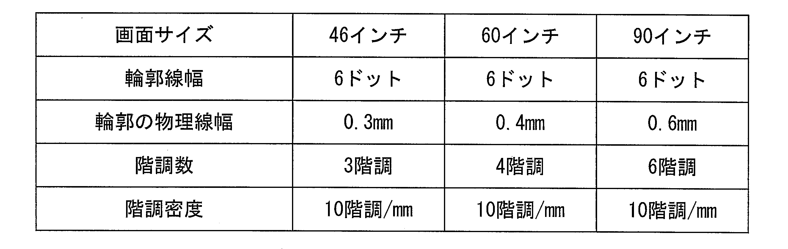
〔テレビジョン受信機の構成〕
次に、輪郭階調数設定装置2として機能するOSD描画部を備えたテレビジョン受信機100について、図4を再度参照して説明する。図4は、テレビジョン受信機100の構成を示すブロック図である。
次に、輪郭階調数設定装置2として機能するOSD描画部を備えたテレビジョン受信機100について、図4を再度参照して説明する。図4は、テレビジョン受信機100の構成を示すブロック図である。
テレビジョン受信機100は、図4に示すように、チューナ部101と、多重分離部102と、選局部103と、映像デコード部104と、映像スケーラ部105と、音声デコード部106と、音声出力部107と、データデコード部108と、OSD生成部109と、OSD描画部110と、外部入力端子111と、映像デコード部112と、映像スケーラ部113と、映像合成部114と、RAM115とを備えている。これらのブロックのうち、OSD描画部110以外のブロックの機能は、従来の受信機のものと同様なので、ここではその説明を割愛する。
このテレビジョン受信機100は、テレビジョン放送(地上デジタル放送、BS放送、CS放送等)を受信する受信機であり、不図示の外付ディスプレイに接続して利用される。OSD描画部110は、テレビジョン受信機100に接続された外付ディスプレイにOSD表示する文字の輪郭階調数を、その外付ディスプレイのサイズに応じて設定する。
この外付ディスプレイは、HDMI(登録商標)などによってテレビジョン受信機100に有線接続されるものであってもよいし、WiFi(登録商標)などによってテレビジョン受信機100に無線接続されるものであってもよい。外付ディスプレイが有線接続される場合、テレビジョン受信機100には、更に、OSD表示される文字が重畳された映像信号で変調された電気信号を生成する通信部と、通信部により生成された電気信号を外部に出力するための出力端子とが付加される。一方、外付ディスプレイが無線接続される場合、テレビジョン受信機100には、更に、OSD表示される文字が重畳された映像信号で変調された電気信号を生成する通信部と、通信部により生成された電気信号を電磁波に変換するアンテナとが付加される。
なお、外付ディスプレイと有線接続される場合、テレビジョン受信機100は、外付ディスプレイとの有線接続が確立された時点で、その外付ディスプレイのサイズ(対象ディスプレイサイズX)を示すサイズ情報(HDMI接続の場合はEDID)を外付ディスプレイから取得し、取得したサイズ情報をRAM115に格納する。また、外付ディスプレイと無線接続される場合、テレビジョン受信機100は、外付ディスプレイとの無線接続が確立された時点(ペアリングが成立した時点)で、その外付ディスプレイのサイズ(対象ディスプレイサイズX)を示すサイズ情報を外付ディスプレイから取得し、取得したサイズ情報をRAM115に格納する。
基準ディスプレイサイズYと基準輪郭階調数Mは、出荷前に予めRAM115に格納されている。したがって、OSD描画部110は、外付ディスプレイとの接続が確立された後、任意のタイミングで対象ディスプレイサイズX、基準ディスプレイサイズY、及び、基準輪郭階調数MをRAM115から読み出すことが可能である。
OSD描画部110は、図9に示したフローチャートに従って、輪郭階調数N’を算出する。この際、サイズ取得ステップS41においては、OSD描画部110が、対象ディスプレイサイズX、基準ディスプレイサイズY、及び基準輪郭階調数MをRAM115から読み出すことになる。
OSD描画部110は、OSD生成部109から文字コードが供給されると、その文字コードに対応するフォントをRAM115から読み出し、映像信号に重畳する文字画像を生成する。この際、文字画像に含まれる文字を構成する字画の周囲に付す輪郭線の階調数を、上記のように設定された輪郭階調数N’とする。これにより、テレビジョン受信機100に接続される外付ディスプレイが基準ディスプレイよりも大きい場合であっても小さい場合であっても、常に、適切な輪郭階調数を有する文字が外付ディスプレイに表示されることになる。
なお、ここでは、ディスプレイ(外付ディスプレイ)に接続されるテレビジョン受信機のOSD描画部を輪郭階調数設定装置2として動作させる構成について説明したが、これに限定されるものではない。すなわち、ディスプレイ(内蔵ディスプレイ)が内蔵されたテレビジョン受信機(つまり、テレビジョン受像機)のOSD描画部を輪郭階調数設定装置2として動作させる構成を採用してもよい。この場合、どのようなサイズの内蔵ディスプレイを備えたテレビジョン受信機であっても、OSD描画部の輪郭階調数設定装置2として機能を変更することなく、適切な輪郭階調数を有する文字を内蔵ディスプレイに表示することができる。特に、OSD描画部の輪郭階調数設定装置2として機能をソフトウェアとして実現する場合には、どのようなサイズの内蔵ディスプレイを備えたテレビジョン受信機であっても、OSD描画部を輪郭階調数設定装置2として動作させるためのプログラムを変更することなく、適切な輪郭階調数を有する文字を内蔵ディスプレイに表示することができる。
また、ここでは、輪郭階調数設定装置2として機能するOSD描画部を備えたテレビジョン受信機について説明したが、輪郭階調数設定装置2を搭載可能な装置は、テレビジョン受信機に限定されない。例えば、文字が重畳された映像を出力する映像出力装置であれば、映像を受信する機能を有さない装置であっても、本発明を適用することが可能である。例えば、DVDプレーヤやBDプレーヤなどの再生装置は、そのような映像出力装置の一例である。この場合、出力する映像に重畳する文字の輪郭階調数を、映像の出力先となるディスプレイのサイズに応じて設定することになる。
なお、ここで説明したテレビジョン受信器、テレビジョン受像機、及び再生装置の外観は、例えば、図15に示したものと同様である。
〔第4の実施形態〕
本発明の第4の実施形態に係る輪郭階調数設定装置について、図面に基づいて説明すれば以下のとおりである。
本発明の第4の実施形態に係る輪郭階調数設定装置について、図面に基づいて説明すれば以下のとおりである。
本実施形態に係る輪郭階調数設定装置は、ディスプレイに表示する文字に付す輪郭線の階調数(以下、「輪郭階調数」とも記載)を、そのディスプレイのサイズ、及び、そのディスプレイに縮小表示される画面のサイズの双方に応じた値に設定するための装置であり、例えば、テレビジョン受信機に搭載することができる。ここで、前記実施形態と同様に、「画面のサイズ」とは、ディスプレイに縮小表示される画面の論理サイズのことを指し、例えば、水平画素数X1と垂直画素数Y1との対(水平画素数X1、垂直画素数Y1)により表される。
ディスプレイに縮小表示される画面の例について、図5を再度参照して説明する。
図5(a)は、2画面表示中のディスプレイの正面図である。この場合、本実施形態に係る輪郭階調数設定装置は、ディスプレイの左側に縮小表示された左画面に表示する文字「DTV」に付す輪郭階調数を、ディスプレイの物理サイズ、及び、当該左画面の論理サイズの双方に応じて設定することになる。
図5(b)は、PinP表示中のディスプレイの正面図である。この場合、本実施形態に係る輪郭階調数設定装置は、ディスプレイの一部に縮小表示された子画面に表示する文字「DTV」に付す輪郭階調数を、ディスプレイの物理サイズ、及び、当該左画面の論理サイズの双方に応じて設定することになる。
〔輪郭階調数設定装置2’の構成〕
本実施形態に係る輪郭階調数設定装置2’の構成について、図11を参照して説明する。図11は、輪郭階調数設定装置2’の構成を示すブロック図である。なお、第3の実施形態にて説明した部材と同じ機能を有する部材については、同じ符号を付記し、その説明を省略する。
本実施形態に係る輪郭階調数設定装置2’の構成について、図11を参照して説明する。図11は、輪郭階調数設定装置2’の構成を示すブロック図である。なお、第3の実施形態にて説明した部材と同じ機能を有する部材については、同じ符号を付記し、その説明を省略する。
輪郭階調数設定装置2’は、図11に示すように、第3の実施形態に係る輪郭階調数設定装置2と同様の構成に加え、画面サイズ取得部26と、画面サイズ比率算出部27と、縮小表示階調数算出部28とを更に備えている。
画面サイズ取得部26は、ディスプレイに縮小表示される画面(以下、「縮小画面」とも記載)のサイズを取得するための構成である。画面サイズ取得部26は、縮小画面のサイズを示す縮小画面サイズ(X1、Y1)を取得する。また、画面サイズ取得部26は、ディスプレイの全画面サイズ(X2、Y2)を取得する。ここで、全画面サイズとは、ディスプレイの論理サイズ(例えば、ドットを単位とする整数値)のことを指す。本実施形態においては、X2=1920ドット、Y2=1080ドットであると仮定する。画面サイズ取得部26が取得した縮小画面サイズ(X1、Y1)、及び全画面サイズ(X2、Y2)は、後述する画面サイズ比率算出部27に供給される。
画面サイズ比率算出部27は、ディスプレイの全画面サイズと、縮小画面サイズとの比率を示す画面サイズ比率Pを算出するための構成である。画面サイズ比率算出部27による比率Pの算出は、例えば、以下の手順により実行される。画面サイズ比率算出部27は、縮小画面の水平画素数X1を、ディスプレイの水平画素数X2で除算した商X1/X2と、縮小画面の垂直画素数Y1を、ディスプレイの垂直画素数Y2で除算した商Y1/Y2とをそれぞれ算出する。画面サイズ比率算出部27は、商X1/X2と、商Y1/Y2とを比較し、(X1/X2)<(Y1/Y2)である場合には、X1/X2を画面サイズ比率Pとして設定する。一方、画面サイズ比率算出部27は、(X1/X2)≧(Y1/Y2)である場合には、Y1/Y2を画面サイズ比率Pとして設定する。画面サイズ比率算出部27により算出された画面サイズ比率Pは、縮小表示階調数算出部28に供給される。なお、画面サイズ比率Pは、例えば、無単位の小数値(所定の桁数を有する)として与えられる。
階調数算出部24は、第3の実施形態にて説明したように、対象ディスプレイサイズXに比例する輪郭階調数N=M*(X/Y)を算出する。本実施形態において、階調数算出部24によって算出された輪郭階調数Nは、図11に示すように、縮小表示階調数算出部28に供給される。
縮小表示階調数算出部28は、対象ディスプレイサイズ(X)及び縮小画面サイズ(X1又はY1)の双方に比例する輪郭階調数N1=P*Nを算出するための構成である。縮小表示階調数算出部28によるN1=P*Nの算出は、例えば、階調数算出部24から供給された輪郭階調数Nと、画面サイズ比率算出部27から供給された画面サイズ比率Pとを乗算することにより実現される。縮小表示階調数算出部28によって算出された輪郭階調数N1は、図11に示すように、整数化部25に供給される。なお、輪郭階調数N1は、無単位の小数値(所定の桁数を有する)として与えられる。
整数化部25は、小数値である輪郭階調数N1を整数化することによって、整数値である輪郭階調数N’を得るための構成である。整数化部25による輪郭階調数N1の整数化は、例えば、以下のように行われる。すなわち、対象ディスプレイサイズXが基準ディスプレイのサイズYよりも大きい場合、整数化部25は、輪郭階調数N1の小数部分を切り上げることによって輪郭階調数N’を得る。一方、対象ディスプレイサイズXが基準ディスプレイのサイズY以下である場合、整数化部25は、輪郭階調数N1の小数部分を切り捨てることによって輪郭階調数N’を得る。
このように、輪郭階調数設定装置2’を用いれば、対象ディスプレイに表示する文字の輪郭階調数N’を、その対象ディスプレイサイズX、及び、縮小画面サイズ(X1又はY1)の双方に略比例する(整数精度で比例する)値に設定することができる。
〔輪郭階調数設定方法〕
次に、輪郭階調数設定装置2を用いた輪郭階調数設定方法について、図12の(a)を参照して説明する。図12の(a)は、本輪郭階調数設定方法の流れを示すフローチャートである。
次に、輪郭階調数設定装置2を用いた輪郭階調数設定方法について、図12の(a)を参照して説明する。図12の(a)は、本輪郭階調数設定方法の流れを示すフローチャートである。
本輪郭階調数設定方法は、図12に示すように、サイズ取得ステップS51と、比率算出ステップS52と、階調数算出ステップS53と、縮小表示階調数算出ステップS55と、整数化ステップS54とを含む。
サイズ取得ステップS51は、対象ディスプレイサイズX、基準ディスプレイサイズY、及び基準輪郭階調数Mを取得するステップである。上述したとおり、対象ディスプレイサイズXの取得は、ディスプレイサイズ取得部21によって実行され、基準ディスプレイサイズY及び基準輪郭階調数Mの取得は、基準サイズ取得部22によって実行される。
比率算出ステップS52は、サイズ取得ステップS51にて取得した対象ディスプレイサイズX及び基準ディスプレイサイズYから、比率X/Yを算出するステップである。上述したとおり、比率X/Yの算出は、比率算出部23によって実行される。
階調数算出ステップS53は、サイズ取得ステップS51にて取得した基準輪郭階調数M、及び、比率算出ステップS52にて算出した比率X/Yから、輪郭階調数N=M*(X/Y)を算出するステップである。上述したとおり、輪郭階調数Nの算出は、階調数算出部24によって実行される。
縮小表示階調数算出ステップS55は、画面サイズ比率P(縮小率)を算出すると共に、対象ディスプレイサイズ(X)及び縮小画面サイズ(X1、Y1)の双方に比例する輪郭階調数N1=P*Nを算出するステップである。上述したとおり、輪郭線幅W1の算出は、縮小表示階調数算出部28によって実行される。なお、画面サイズ比率Pの算出方法については、参照する図面を代えて後述する。
整数化ステップS54は、縮小表示階調数算出ステップS55にて算出した輪郭階調数N1を整数化するステップである。上述したとおり、輪郭階調数N1の整数化は、整数化部25によって実行される。整数化ステップS54は、例えば、判定ステップS541と、切上ステップS542と、切捨ステップS543とにより構成される。
判定ステップS541は、対象ディスプレイサイズXと基準ディスプレイサイズYとの大小比較を行うステップである。X>Yである場合、整数化部25は、後述する切上ステップS542を実行する。一方、X≦Yである場合、整数化部25は、後述する切捨ステップS543を実行する。
切上ステップS542は、輪郭階調数N1の小数部分を切り上げることによって、整数値である輪郭階調数N’を得るステップである。N1の整数部分がnである場合、切上ステップS542においてN’=n+1が得られる。
切捨ステップS543は、輪郭階調数N1の小数部分を切り捨てることによって、整数値である輪郭階調数N’を得るステップである。N1の整数部分がnである場合、切捨ステップS543においてN’=nが得られる。
このように、本輪郭階調数設定方法を用いれば、対象ディスプレイに表示する文字の輪郭階調数N’を、その対象ディスプレイサイズX、及び、縮小画面サイズ(X1又はY1)に略比例する(整数精度で比例する)値に設定することができる。
〔画面サイズ比率の算出〕
次に、縮小表示階調数算出ステップS55における画面サイズ比率Pの算出方法について、図12の(b)を参照して説明する。図12の(b)は、本輪郭線幅設定方法における画面サイズ比率Pの算出の流れを示すフローチャートである。
次に、縮小表示階調数算出ステップS55における画面サイズ比率Pの算出方法について、図12の(b)を参照して説明する。図12の(b)は、本輪郭線幅設定方法における画面サイズ比率Pの算出の流れを示すフローチャートである。
画面サイズ取得ステップS61は、ディスプレイに表示される画面のサイズを取得するためのステップである。上述したとおり、画面サイズの取得は、画面サイズ取得部26によって実行される。画面サイズ取得部26は、画面サイズ取得ステップS61にて、全画面サイズ、及び縮小画面サイズを取得する。画面サイズ取得ステップS61にて取得された全画面サイズ、及び縮小画像サイズは、画面サイズ比率算出部27に供給される。
ステップS62~S64は、ディスプレイの全画面サイズに対する、縮小画面サイズの比率を示す画面サイズ比率Pを算出するためのステップである。上述したように画面サイズ比率算出部27によって、ステップS62~S64が実行される。
画面サイズ比率算出部27は、判定ステップS62にて、縮小画面の水平画素数X1を、ディスプレイの水平画素数1920で除算した商X1/1920と、縮小画面の垂直画素数Y1を、ディスプレイの垂直画素数1080で除算した商Y1/1080とをそれぞれ算出する。画面サイズ比率算出部27は、商X1/1920と商Y1/1080とを比較する。画面サイズ比率算出部27は、(X1/1920)<(Y1/1080)である場合には、X1/1920を画面サイズ比率Pとして設定する(設定ステップS63)。一方、画面サイズ比率算出部17は、(X1/1920)≧(Y1/1080)である場合には、Y1/1080を画面サイズ比率Pとして設定する(設定ステップS64)。
以上の手順により、輪郭階調数設定装置2’は、画面サイズ比率Pを算出することができる。
なお、本輪郭階調数設定方法は、第3の実施形態に係る輪郭階調数設定方法と同様に、テレビジョン受像機の製造方法に応用することができる。この場合、本輪郭階調数設定方法は、製造対象となるテレビジョン受像機の内蔵ディスプレイにOSD表示する文字の輪郭階調数を、その内蔵ディスプレイのサイズ、及び、内蔵ディスプレイに表示される縮小画面のサイズの双方に応じて設定するために用いられる。本輪郭階調数設定方法を用いて設定された輪郭階調数は、例えば、製造対象となるテレビジョン受像機の内蔵記録媒体に記録される。このようにして製造されたテレビジョン受像機は、内蔵ディスプレイに文字をOSD表示する際に、本輪郭階調数設定方法を用いて設定され、内蔵記録媒体に記録された輪郭階調数を参照することができる。
なお、本輪郭階調数設定方法をテレビジョン受像機の製造方法に応用する場合、本輪郭階調数設定方法を構成する各ステップを実行する処理主体は、テレビジョン受像機を製造する製造する製造装置(輪郭階調数設定装置2’を備えた製造装置)であってもよいし、テレビ受像機を製造する製造者(作業者)であってもよい。
〔テレビジョン受信機の構成〕
次に、輪郭階調数設定装置2’として機能するOSD描画部を備えたテレビジョン受信機100について、図4を再度参照して説明する。図4は、テレビジョン受信機100の構成を示すブロック図である。本実施形態において、テレビジョン受信機100は、OSD描画部110が、輪郭階調数設定装置2’として機能するという点において、第2の実施形態にて説明したテレビジョン受信機100と異なる。すなわち、OSD描画部110は、テレビジョン受信機100に接続された外付ディスプレイにOSD表示する文字の輪郭階調数を、その外付ディスプレイのサイズ、及び、外付けディスプレイに表示される縮小画面のサイズの双方に応じて設定する。
次に、輪郭階調数設定装置2’として機能するOSD描画部を備えたテレビジョン受信機100について、図4を再度参照して説明する。図4は、テレビジョン受信機100の構成を示すブロック図である。本実施形態において、テレビジョン受信機100は、OSD描画部110が、輪郭階調数設定装置2’として機能するという点において、第2の実施形態にて説明したテレビジョン受信機100と異なる。すなわち、OSD描画部110は、テレビジョン受信機100に接続された外付ディスプレイにOSD表示する文字の輪郭階調数を、その外付ディスプレイのサイズ、及び、外付けディスプレイに表示される縮小画面のサイズの双方に応じて設定する。
OSD描画部110は、図12に示したフローチャートに従って、輪郭階調数N’を算出する。この際、サイズ取得ステップS51においては、OSD描画部110が、対象ディスプレイサイズX、基準ディスプレイサイズY、及び基準輪郭階調数M(出荷前に予めRAM115に格納されている)をRAM115から読み出すことになる。また、画面サイズ取得ステップS61においては、OSD描画部110が、全画面サイズ(X2、Y2)、及び縮小画面サイズ(X1、Y1)をRAM115から読み出すことになる。
OSD描画部110は、OSD生成部109から文字コードが供給されると、その文字コードに対応するフォントをRAM115から読み出し、映像信号に重畳する文字画像を生成する。この際、文字画像に含まれる文字を構成する字画の周囲に付す輪郭線の階調数を、上記のように設定された輪郭階調数N’とする。これにより、テレビジョン受信機100に接続される外付ディスプレイが基準ディスプレイよりも大きい場合であっても小さい場合であっても、常に、外付ディスプレイに表示される縮小画面のサイズに応じた適切な輪郭階調数を有する文字が外付ディスプレイに表示されることになる。
なお、ここで説明したテレビジョン受信器、テレビジョン受像機、及び再生装置の外観は、例えば、図15に示したものと同様である。
〔ソフトウェアによる実現例〕
最後に、輪郭線幅設定装置1、輪郭線幅設定装置1’、輪郭階調数設定装置2、及び、輪郭階調数設定装置2’の各ブロックは、集積回路(ICチップ)上に形成された論理回路によってハードウェア的に実現してもよいし、CPU(Central Processing Unit)を用いてソフトウェア的に実現してもよい。
最後に、輪郭線幅設定装置1、輪郭線幅設定装置1’、輪郭階調数設定装置2、及び、輪郭階調数設定装置2’の各ブロックは、集積回路(ICチップ)上に形成された論理回路によってハードウェア的に実現してもよいし、CPU(Central Processing Unit)を用いてソフトウェア的に実現してもよい。
後者の場合、輪郭線幅設定装置1、輪郭線幅設定装置1’、輪郭階調数設定装置2、及び、輪郭階調数設定装置2’は、各機能を実現するプログラムの命令を実行するCPU、上記プログラムを格納したROM(Read Only Memory)、上記プログラムを展開するRAM(Random Access Memory)、上記プログラムおよび各種データを格納するメモリ等の記憶装置(記録媒体)などを備えている。そして、本発明の目的は、上述した機能を実現するソフトウェアである輪郭線幅設定装置1、輪郭線幅設定装置1’、輪郭階調数設定装置2、及び、輪郭階調数設定装置2’の制御プログラムのプログラムコード(実行形式プログラム、中間コードプログラム、ソースプログラム)をコンピュータで読み取り可能に記録した記録媒体を、上記輪郭線幅設定装置1、輪郭線幅設定装置1’、輪郭階調数設定装置2、及び、輪郭階調数設定装置2’に供給し、そのコンピュータ(またはCPUやMPU)が記録媒体に記録されているプログラムコードを読み出し実行することによっても、達成可能である。
上記記録媒体としては、一時的でない有形の媒体(non-transitory tangible medium)、例えば、磁気テープやカセットテープ等のテープ類、フロッピー(登録商標)ディスク/ハードディスク等の磁気ディスクやCD-ROM/MO/MD/DVD/CD-R等の光ディスクを含むディスク類、ICカード(メモリカードを含む)/光カード等のカード類、マスクROM/EPROM/EEPROM(登録商標)/フラッシュROM等の半導体メモリ類、あるいはPLD(Programmable logic device)やFPGA(Field Programmable Gate Array)等の論理回路類などを用いることができる。
また、輪郭線幅設定装置1、輪郭線幅設定装置1’、輪郭階調数設定装置2、及び、輪郭階調数設定装置2’を通信ネットワークと接続可能に構成し、上記プログラムコードを通信ネットワークを介して供給してもよい。この通信ネットワークは、プログラムコードを伝送可能であればよく、特に限定されない。例えば、インターネット、イントラネット、エキストラネット、LAN、ISDN、VAN、CATV通信網、仮想専用網(Virtual Private Network)、電話回線網、移動体通信網、衛星通信網等が利用可能である。また、この通信ネットワークを構成する伝送媒体も、プログラムコードを伝送可能な媒体であればよく、特定の構成または種類のものに限定されない。例えば、IEEE1394、USB、電力線搬送、ケーブルTV回線、電話線、ADSL(Asymmetric Digital Subscriber Line)回線等の有線でも、IrDAやリモコンのような赤外線、Bluetooth(登録商標)、IEEE802.11無線、HDR(High Data Rate)、NFC(Near Field Communication)、DLNA(Digital Living Network Alliance、登録商標)、携帯電話網、衛星回線、地上波デジタル網等の無線でも利用可能である。なお、本発明は、上記プログラムコードが電子的な伝送で具現化された、搬送波に埋め込まれたコンピュータデータ信号の形態でも実現され得る。
〔まとめ〕
本発明の一態様に係る輪郭線幅設定装置(1)は、ディスプレイのサイズを取得するディスプレイサイズ取得手段(11)と、上記ディスプレイサイズ取得手段(11)が取得した上記ディスプレイのサイズに略反比例するように、上記ディスプレイに表示する文字の輪郭線幅を設定する輪郭線幅設定手段(13、14、15)と、を備えている。
本発明の一態様に係る輪郭線幅設定装置(1)は、ディスプレイのサイズを取得するディスプレイサイズ取得手段(11)と、上記ディスプレイサイズ取得手段(11)が取得した上記ディスプレイのサイズに略反比例するように、上記ディスプレイに表示する文字の輪郭線幅を設定する輪郭線幅設定手段(13、14、15)と、を備えている。
上記の構成によれば、どのようなサイズのディスプレイに対しても、文字に付される輪郭線の物理幅を略一定にすることができる。これにより、輪郭線を有する文字を高品位に表示することが可能になる。
本発明の一態様に係る輪郭線幅設定装置(1)においては、上記ディスプレイサイズ取得手段(11)が取得した上記ディスプレイのサイズをX、予め定められた基準ディスプレイのサイズをY、予め定められた基準輪郭線の線幅をVとして、上記輪郭線幅設定手段(13、14、15)が、小数値である輪郭線幅W=V*(Y/X)を算出する輪郭線幅算出手段(13、14)と、上記輪郭線幅算出手段(13、14)により算出された輪郭線幅Wを整数化することによって、整数値である輪郭線幅W’を算出する輪郭線幅整数化手段(15)とを含んでいる、ことが好ましい。
上記の構成によれば、ディスプレイのサイズに略反比例する輪郭線幅を、簡単な構成で高速に導出することができる。
本発明の一態様に係る輪郭線幅設定装置(1)においては、上記輪郭線幅算出手段(13、14)により算出された輪郭線幅Wの整数部分をnとして、上記輪郭線幅整数化手段(15)が、上記ディスプレイのサイズXが上記基準ディスプレイのサイズYよりも大きい場合、輪郭線幅W’をnとし、上記ディスプレイのサイズXが上記基準ディスプレイのサイズYよりも小さい場合、輪郭線幅W’をn+1とする、ことが好ましい。
上記の構成によれば、基準ディスプレイよりもサイズの大きなディスプレイに表示する文字の輪郭線幅が太くなり過ぎたり、基準ディスプレイよりもサイズの小さなディスプレイに表示する文字の輪郭線幅が細くなり過ぎたりするといった事態を招来することなく、設定する輪郭線幅を整数化することができる。
本発明の一態様に係る輪郭線幅設定装置(1’)においては、上記ディスプレイに縮小表示される画面のサイズを取得する画面サイズ取得手段(16)を更に備え、上記輪郭線幅設定手段(13、14、15、18)は、上記ディスプレイサイズ取得手段(11)が取得した上記ディスプレイのサイズ、及び、上記画面サイズ取得手段(16)が取得した上記画面のサイズの双方に略反比例するように、上記ディスプレイに表示する文字の輪郭線幅を設定する、ことが好ましい。
上記の構成によれば、ディスプレイに縮小表示される画面に対しても、文字に付される輪郭線の物理幅を略一定にすることができる。これにより、輪郭線を有する文字を高品位に表示することが可能になる。
本発明の一態様に係る輪郭線幅設定装置(1’)においては、上記画面サイズ取得手段(16)は、上記ディスプレイに縮小表示される画面の水平画素数X1、及び垂直画素数Y1を取得するものであり、上記ディスプレイの水平画素数をX2、上記ディスプレイの垂直画素数をY2として、上記輪郭線幅設定手段(13、14、15、18)は、(1)(X2/X1)が(Y2/Y1)よりも大きい場合、画面サイズ比率Pを(X2/X1)とし、(2)(X2/X1)が(Y2/Y1)よりも小さい場合、画面サイズ比率Pを(Y2/Y1)として、小数値である輪郭線幅W1=P*V*(Y/X)を算出する輪郭線幅算出手段(13、14、18)と、上記輪郭線幅算出手段(13、14、18)により算出された輪郭線幅W1を整数化することによって、整数値である輪郭線幅W’を算出する輪郭線幅整数化手段(15)とを含んでいる、ことが好ましい。
上記の構成によれば、上記ディスプレイに縮小表示される画面が、アスペクト比を変更するように画面のサイズを縮小されている場合においても、適切な画面サイズ比率Pを設定することができる。これにより、輪郭線を有する文字を高品位に表示することが可能になる。
本発明の一態様に係る輪郭線幅設定方法は、ディスプレイのサイズを取得する取得ステップ(S11)と、上記取得ステップ(S11)にて取得した上記ディスプレイのサイズに略反比例するように、上記ディスプレイに表示する文字の輪郭線幅を設定する設定ステップ(S12、S13、S14)と、を含んでいる。
上記の構成によれば、どのようなサイズのディスプレイに対しても、文字に付される輪郭線の物理幅を略一定にすることができる。これにより、輪郭線を有する文字を高品位に表示することが可能になる。
なお、上記輪郭線幅設定装置(1、1’、110)を備えたテレビジョン受信機(100)であって、当該テレビジョン受信機(100)に接続又は内蔵されたディスプレイにOSD表示する文字の輪郭線幅を上記輪郭線幅設定装置(1、1’、110)を用いて設定するテレビジョン受信機(100)も本発明の範疇に含まれる。
また、上記輪郭線幅設定方法を含んだテレビジョン受信機の製造方法であって、上記テレビジョン受信機に内蔵されたディスプレイにOSD表示する文字の輪郭線幅を上記輪郭線幅設定方法を用いて設定するテレビジョン受像機の製造方法も本発明の範疇に含まれる。
また、コンピュータを上記輪郭線幅設定装置(1、1’)として動作させるためのプログラムであって、上記コンピュータを上記輪郭線幅設定装置(1、1’)の上記各手段(11、13、14、15、16、17、18)として機能させるためのプログラム、及び、上記プログラムが記録されているコンピュータ読み取り可能な記録媒体も本発明の範疇に含まれる。
本発明の一態様に係る輪郭階調数設定装置(2)は、ディスプレイのサイズを取得するディスプレイサイズ取得手段(21)と、上記ディスプレイサイズ取得手段(21)が取得した上記ディスプレイのサイズに略比例するように、上記ディスプレイに表示する文字の輪郭階調数を設定する輪郭階調数設定手段(23、24、25)と、を備えている。
上記の構成によれば、どのようなディスプレイに対しても、文字に付される輪郭線の階調数密度(単位長さ辺りの階調数)を略一定にすることができる。これにより、多階調の輪郭線を有する文字を高品位に表示することが可能になる。
本発明の一態様に係る輪郭階調数設定装置(2)においては、上記ディスプレイサイズ取得手段(21)が取得した上記ディスプレイのサイズをX、予め定められた基準ディスプレイのサイズをY、予め定められた基準輪郭線の階調数をMとして、上記輪郭階調数設定手段(23、24、25)が、小数値である階調数N=M*(X/Y)を算出する輪郭階調数算出手段(23、24)と、上記輪郭階調数算出手段により算出された階調数Nを整数化することによって、整数値である階調数N’を算出する輪郭階調数整数化手段(25)とを含んでいる、ことが好ましい。
上記の構成によれば、ディスプレイのサイズに略比例する階調数を、簡単な構成で高速に導出することができる。
本発明の一態様に係る輪郭階調数設定装置(2)においては、上記輪郭階調数算出手段(23、24)により算出された階調数Nの整数部分をnとして、上記輪郭階調数整数化手段(25)が、上記ディスプレイのサイズXが上記基準ディスプレイのサイズYよりも大きい場合、階調数N’をn+1とし、上記ディスプレイのサイズXが上記基準ディスプレイのサイズYよりも小さい場合、階調数N’をnとする、ことが好ましい。
上記の構成によれば、基準ディスプレイよりもサイズの大きなディスプレイに表示する文字の階調密度が低くなり過ぎたり、基準ディスプレイよりもサイズの小さなディスプレイに表示する文字の階調密度が高くなり過ぎたりするといった事態を招来することなく、設定する階調数を整数化することができる。
本発明の一態様に係る輪郭階調数設定装置(2’)においては、上記ディスプレイに縮小表示される画面のサイズを取得する画面サイズ取得手段(26)を更に備え、上記輪郭階調数設定手段(23、24、25、28)は、上記ディスプレイサイズ取得手段(21)が取得した上記ディスプレイのサイズ、及び、上記画面サイズ取得手段(26)が取得した上記画面のサイズの双方に略比例するように、上記画面に表示する文字に付す輪郭線の階調数を設定する、ことが好ましい。
上記の構成によれば、ディスプレイに縮小表示される画面に対しても、文字に付される輪郭線の階調数密度(単位長さ辺りの階調数)を略一定にすることができる。これにより、多階調の輪郭線を有する文字を高品位に表示することが可能になる。
本発明の一態様に係る輪郭階調数設定装置(2’)においては、上記画面サイズ取得手段(26)は、上記ディスプレイに縮小表示される画面の水平画素数X1、及び垂直画素数Y1を取得するものであり、上記ディスプレイの水平画素数をX2、上記ディスプレイの垂直画素数をY2として、上記輪郭階調数設定手段(23、24、25、28)は、(1)(Y1/Y2)が(X1/X2)よりも大きい場合、画面サイズ比率Pを(X1/X2)とし、(2)(Y1/Y2)が(X1/X2)よりも小さい場合、画面サイズ比率Pを(Y1/Y2)として、小数値である階調数N1=P*M*(X/Y)を算出する輪郭線幅算出手段(23、24、28)と、上記輪郭線幅算出手段(23、24、28)により算出された階調数N1を整数化することによって、整数値である階調数N’を算出する輪郭階調数整数化手段(25)とを含んでいる、ことが好ましい。
上記の構成によれば、上記ディスプレイに縮小表示される画面が、アスペクト比を変更するように画面のサイズを縮小されている場合においても、適切な画面サイズ比率Pを設定することができる。これにより、輪郭線を有する文字を高品位に表示することが可能になる。
本発明の一態様に係る輪郭階調数設定方法は、ディスプレイのサイズを取得する取得ステップ(S41)と、上記取得ステップ(S41)にて取得した上記ディスプレイのサイズに略比例するように、上記ディスプレイに表示する文字に付す輪郭線の階調数を設定する設定ステップ(S42、S43、S44)と、を含んでいる。
上記の構成によれば、どのようなディスプレイに対しても、文字に付される輪郭線の階調数密度(単位長さ辺りの階調数)を略一定にすることができる。これにより、多階調の輪郭線を有する文字を高品位に表示することが可能になる。
なお、上記輪郭階調数設定装置(2、2’、110)を備えたテレビジョン受信機(100)であって、当該テレビジョン受信機(100)に接続又は内蔵されたディスプレイにOSD表示する文字に付す輪郭線の階調数を上記輪郭階調数設定装置(2、2’、110)を用いて設定するテレビジョン受信機(100)も本発明の範疇に含まれる。
また、上記輪郭階調数設定方法を含んだテレビジョン受信機の製造方法であって、上記テレビジョン受信機に内蔵されたディスプレイにOSD表示する文字に付す輪郭線の階調数を上記輪郭階調数設定方法を用いて設定するテレビジョン受像機の製造方法も本発明の範疇に含まれる。
また、コンピュータを上記輪郭階調数設定装置(2、2’)として動作させるためのプログラムであって、上記コンピュータを上記輪郭階調数設定装置(2、2’)の上記各手段(21、23、24、25、26、27、28)として機能させるためのプログラム、及び、上記プログラムが記録されているコンピュータ読み取り可能な記録媒体も本発明の範疇に含まれる。
〔付記事項〕
本発明は上述した各実施形態に限定されるものではなく、請求項に示した範囲で種々の変更が可能であり、異なる実施形態にそれぞれ開示された技術的手段を適宜組み合わせて得られる実施形態についても本発明の技術的範囲に含まれる。さらに、各実施形態にそれぞれ開示された技術的手段を組み合わせることにより、新しい技術的特徴を形成することができる。
本発明は上述した各実施形態に限定されるものではなく、請求項に示した範囲で種々の変更が可能であり、異なる実施形態にそれぞれ開示された技術的手段を適宜組み合わせて得られる実施形態についても本発明の技術的範囲に含まれる。さらに、各実施形態にそれぞれ開示された技術的手段を組み合わせることにより、新しい技術的特徴を形成することができる。
本発明は、ディスプレイに文字をOSD表示する各種AV機器、例えば、テレビジョン受信機、テレビジョン受像機、BDプレーヤ、DVDプレーヤなどにおいて利用することができる。
1 輪郭線幅設定装置
11 ディスプレイサイズ取得部
12 基準サイズ取得部
13 比率算出部
14 線幅算出部
15 整数化部
16 画面サイズ取得部
17 画面サイズ比率算出部
18 縮小表示線幅算出部
100 テレビジョン受信機
110 OSD描画部(輪郭線幅設定装置、輪郭階調数設定装置)
2 輪郭階調数設定装置
21 ディスプレイサイズ取得部
22 基準サイズ取得部
23 比率算出部
24 階調数算出部
25 整数化部
26 画面サイズ取得部
27 画面サイズ比率算出部
28 縮小表示階調数算出部
11 ディスプレイサイズ取得部
12 基準サイズ取得部
13 比率算出部
14 線幅算出部
15 整数化部
16 画面サイズ取得部
17 画面サイズ比率算出部
18 縮小表示線幅算出部
100 テレビジョン受信機
110 OSD描画部(輪郭線幅設定装置、輪郭階調数設定装置)
2 輪郭階調数設定装置
21 ディスプレイサイズ取得部
22 基準サイズ取得部
23 比率算出部
24 階調数算出部
25 整数化部
26 画面サイズ取得部
27 画面サイズ比率算出部
28 縮小表示階調数算出部
Claims (14)
- ディスプレイのサイズを取得するディスプレイサイズ取得手段と、
上記ディスプレイサイズ取得手段が取得した上記ディスプレイのサイズに略反比例するように、上記ディスプレイに表示する文字の輪郭線幅を設定する輪郭線幅設定手段と、を備えていることを特徴とする輪郭線幅設定装置。 - 上記ディスプレイサイズ取得手段が取得した上記ディスプレイのサイズをX、予め定められた基準ディスプレイのサイズをY、予め定められた基準輪郭線の線幅をVとして、
上記輪郭線幅設定手段は、小数値である輪郭線幅W=V*(Y/X)を算出する輪郭線幅算出手段と、上記輪郭線幅算出手段により算出された輪郭線幅Wを整数化することによって、整数値である輪郭線幅W’を算出する輪郭線幅整数化手段とを含んでいる、ことを特徴とする請求項1に記載の輪郭線幅設定装置。 - 上記輪郭線幅算出手段により算出された輪郭線幅Wの整数部分をnとして、
上記輪郭線幅整数化手段は、(1)上記ディスプレイのサイズXが上記基準ディスプレイのサイズYよりも大きい場合、輪郭線幅W’をnとし、(2)上記ディスプレイのサイズXが上記基準ディスプレイのサイズYよりも小さい場合、輪郭線幅W’をn+1とする、ことを特徴とする請求項2に記載の輪郭線幅設定装置。 - 上記ディスプレイに縮小表示される画面のサイズを取得する画面サイズ取得手段を更に備え、
上記輪郭線幅設定手段は、上記ディスプレイサイズ取得手段が取得した上記ディスプレイのサイズ、及び、上記画面サイズ取得手段が取得した上記画面のサイズの双方に略反比例するように、上記ディスプレイに表示する文字の輪郭線幅を設定する、ことを特徴とする請求項1に記載の輪郭線幅設定装置。 - 上記画面サイズ取得手段は、上記ディスプレイに縮小表示される画面の水平画素数X1及び垂直画素数Y1を取得するものであり、
上記ディスプレイの水平画素数をX2、上記ディスプレイの垂直画素数をY2として、
上記輪郭線幅設定手段は、(1)(X2/X1)が(Y2/Y1)よりも大きい場合、画面サイズ比率Pを(X2/X1)とし、(2)(X2/X1)が(Y2/Y1)よりも小さい場合、画面サイズ比率Pを(Y2/Y1)として、小数値である輪郭線幅W1=P*V*(Y/X)を算出する輪郭線幅算出手段と、上記輪郭線幅算出手段により算出された輪郭線幅W1を整数化することによって、整数値である輪郭線幅W’を算出する輪郭線幅整数化手段とを含んでいる、ことを特徴とする請求項4に記載の輪郭線幅設定装置。 - 請求項1から5までの何れか1項に記載の輪郭線幅設定装置を備えたテレビジョン受信機であって、
当該テレビジョン受信機に接続又は内蔵されたディスプレイにOSD表示する文字の輪郭線幅を上記輪郭線幅設定装置を用いて設定する、ことを特徴とするテレビジョン受信機。 - ディスプレイのサイズを取得するディスプレイサイズ取得手段と、
上記ディスプレイサイズ取得手段が取得した上記ディスプレイのサイズに略比例するように、上記ディスプレイに表示する文字に付す輪郭線の階調数を設定する輪郭階調数設定手段と、を備えていることを特徴とする輪郭階調数設定装置。 - 上記ディスプレイサイズ取得手段が取得した上記ディスプレイのサイズをX、予め定められた基準ディスプレイのサイズをY、予め定められた基準輪郭線の階調数をMとして、
上記輪郭階調数設定手段は、小数値である階調数N=M*(X/Y)を算出する輪郭階調数算出手段と、上記輪郭階調数算出手段により算出された階調数Nを整数化することによって、整数値である階調数N’を算出する輪郭階調数整数化手段とを含んでいる、ことを特徴とする請求項7に記載の輪郭階調数設定装置。 - 上記輪郭階調数算出手段により算出された階調数Nの整数部分をnとして、
上記輪郭階調数整数化手段は、(1)上記ディスプレイのサイズXが上記基準ディスプレイのサイズYよりも大きい場合、階調数N’をn+1とし、(2)上記ディスプレイのサイズXが上記基準ディスプレイのサイズYよりも小さい場合、階調数N’をnとする、ことを特徴とする請求項8に記載の輪郭階調数設定装置。 - 上記ディスプレイに縮小表示される画面のサイズを取得する画面サイズ取得手段を更に備え、
上記輪郭階調数設定手段は、上記ディスプレイサイズ取得手段が取得した上記ディスプレイのサイズ、及び、上記画面サイズ取得手段が取得した上記画面のサイズの双方に略比例するように、上記画面に表示する文字に付す輪郭線の階調数を設定する、ことを特徴とする請求項7に記載の輪郭階調数設定装置。 - 上記画面サイズ取得手段は、上記ディスプレイに縮小表示される画面の水平画素数X1、及び垂直画素数Y1を取得するものであり、
上記ディスプレイの水平画素数をX2、上記ディスプレイの垂直画素数をY2として、
上記輪郭階調数設定手段は、(1)(Y1/Y2)が(X1/X2)よりも大きい場合、画面サイズ比率Pを(X1/X2)とし、(2)(Y1/Y2)が(X1/X2)よりも小さい場合、画面サイズ比率Pを(Y1/Y2)として、小数値である階調数N1=P*M*(X/Y)を算出する輪郭線幅算出手段と、上記輪郭線幅算出手段により算出された階調数N1を整数化することによって、整数値である階調数N’を算出する輪郭階調数整数化手段とを含んでいる、ことを特徴とする請求項10に記載の輪郭階調数設定装置。 - 請求項7から11までの何れか1項に記載の輪郭階調数設定装置を備えたテレビジョン受信機であって、
当該テレビジョン受信機に接続又は内蔵されたディスプレイにOSD表示する文字に付す輪郭線の階調数を上記輪郭階調数設定装置を用いて設定する、ことを特徴とするテレビジョン受信機。 - ディスプレイのサイズを取得するディスプレイサイズ取得ステップと、
上記ディスプレイサイズ取得ステップにて取得した上記ディスプレイのサイズに略反比例するように、上記ディスプレイに表示する文字の輪郭線幅を設定する輪郭線幅設定ステップと、を含んでいることを特徴とする輪郭線幅設定方法。 - ディスプレイのサイズを取得するディスプレイサイズ取得ステップと、
上記ディスプレイサイズ取得ステップにて取得した上記ディスプレイのサイズに略比例するように、上記ディスプレイに表示する文字に付す輪郭線の階調数を設定する輪郭階調数設定ステップと、を含んでいることを特徴とする輪郭階調数設定方法。
Priority Applications (2)
| Application Number | Priority Date | Filing Date | Title |
|---|---|---|---|
| US14/431,196 US20150255044A1 (en) | 2012-09-27 | 2013-09-26 | Contour line width setting device, contour gradation number setting device, contour line width setting method, and contour gradation number setting method |
| CN201380050242.5A CN104662601B (zh) | 2012-09-27 | 2013-09-26 | 轮廓线宽度设定装置、轮廓灰度数设定装置、轮廓线宽度设定方法、以及轮廓灰度数设定方法 |
Applications Claiming Priority (6)
| Application Number | Priority Date | Filing Date | Title |
|---|---|---|---|
| JP2012215206 | 2012-09-27 | ||
| JP2012215205 | 2012-09-27 | ||
| JP2012-215205 | 2012-09-27 | ||
| JP2012-215206 | 2012-09-27 | ||
| JP2013194690A JP5519065B2 (ja) | 2012-09-27 | 2013-09-19 | 輪郭線幅設定装置、輪郭階調数設定装置、輪郭線幅設定方法、及び輪郭階調数設定方法 |
| JP2013-194690 | 2013-09-19 |
Publications (1)
| Publication Number | Publication Date |
|---|---|
| WO2014050984A1 true WO2014050984A1 (ja) | 2014-04-03 |
Family
ID=50388379
Family Applications (1)
| Application Number | Title | Priority Date | Filing Date |
|---|---|---|---|
| PCT/JP2013/076101 Ceased WO2014050984A1 (ja) | 2012-09-27 | 2013-09-26 | 輪郭線幅設定装置、輪郭階調数設定装置、輪郭線幅設定方法、及び輪郭階調数設定方法 |
Country Status (4)
| Country | Link |
|---|---|
| US (1) | US20150255044A1 (ja) |
| JP (1) | JP5519065B2 (ja) |
| CN (1) | CN104662601B (ja) |
| WO (1) | WO2014050984A1 (ja) |
Families Citing this family (5)
| Publication number | Priority date | Publication date | Assignee | Title |
|---|---|---|---|---|
| TW201621705A (zh) * | 2014-12-01 | 2016-06-16 | 富智康(香港)有限公司 | 頁面文字調整方法及系統 |
| WO2019008702A1 (ja) * | 2017-07-05 | 2019-01-10 | 三菱電機株式会社 | 描画装置及び描画方法 |
| CN109348276B (zh) * | 2018-11-08 | 2019-12-17 | 北京微播视界科技有限公司 | 视频画面调整方法、装置、计算机设备和存储介质 |
| US11594163B2 (en) * | 2020-03-06 | 2023-02-28 | Bby Solutions, Inc. | Multiple-sized display presentation system and apparatus |
| US12008812B2 (en) * | 2020-09-30 | 2024-06-11 | Alarm.Com Incorporated | Simultaneous playback of continuous video recordings from multiple recording devices |
Citations (9)
| Publication number | Priority date | Publication date | Assignee | Title |
|---|---|---|---|---|
| JPH0344697A (ja) * | 1989-07-13 | 1991-02-26 | Seiko Epson Corp | ドットパターン発生装置 |
| JPH05161085A (ja) * | 1991-12-09 | 1993-06-25 | Olympus Optical Co Ltd | 映像再生装置 |
| JP2001157027A (ja) * | 1999-11-26 | 2001-06-08 | Fuji Photo Film Co Ltd | 縁付き画像生成方法および装置並びに記録媒体 |
| JP2002041026A (ja) * | 2000-07-19 | 2002-02-08 | Sony Corp | 映像表示方法および映像表示装置 |
| JP2003333449A (ja) * | 2002-05-15 | 2003-11-21 | Funai Electric Co Ltd | 合成画像出力装置 |
| JP2005295338A (ja) * | 2004-04-01 | 2005-10-20 | Sharp Corp | 映像表示装置及び文字画面表示方法 |
| JP2006186485A (ja) * | 2004-12-27 | 2006-07-13 | Sharp Corp | 画像処理装置 |
| JP2008304580A (ja) * | 2007-06-06 | 2008-12-18 | Sharp Corp | 画像表示装置 |
| WO2011070793A1 (ja) * | 2009-12-11 | 2011-06-16 | パナソニック株式会社 | 画像表示装置及び画像表示方法 |
Family Cites Families (7)
| Publication number | Priority date | Publication date | Assignee | Title |
|---|---|---|---|---|
| US5526476A (en) * | 1992-12-07 | 1996-06-11 | Fujitsu Limited | Method and apparatus for generating character patterns expressed by coordinates of a coordinate system |
| US5796409A (en) * | 1993-04-06 | 1998-08-18 | Ecole Polytechnique Federale De Lausanne | Method for producing contrast-controlled grayscale characters |
| JP3483946B2 (ja) * | 1994-08-19 | 2004-01-06 | 三菱電機株式会社 | フォント処理装置及びフォント処理方法 |
| US6597360B1 (en) * | 1998-10-07 | 2003-07-22 | Microsoft Corporation | Automatic optimization of the position of stems of text characters |
| JP3747410B2 (ja) * | 2002-10-04 | 2006-02-22 | インターナショナル・ビジネス・マシーンズ・コーポレーション | アウトラインフォントの印字線幅を設定する技術 |
| JP2004354767A (ja) * | 2003-05-29 | 2004-12-16 | Sharp Corp | 文字図形表示装置、文字図形表示方法、プログラムおよび記録媒体 |
| JP4687725B2 (ja) * | 2008-02-12 | 2011-05-25 | ソニー株式会社 | 画像処理装置及び画像処理方法、並びにコンピュータ・プログラム |
-
2013
- 2013-09-19 JP JP2013194690A patent/JP5519065B2/ja not_active Expired - Fee Related
- 2013-09-26 CN CN201380050242.5A patent/CN104662601B/zh not_active Expired - Fee Related
- 2013-09-26 WO PCT/JP2013/076101 patent/WO2014050984A1/ja not_active Ceased
- 2013-09-26 US US14/431,196 patent/US20150255044A1/en not_active Abandoned
Patent Citations (9)
| Publication number | Priority date | Publication date | Assignee | Title |
|---|---|---|---|---|
| JPH0344697A (ja) * | 1989-07-13 | 1991-02-26 | Seiko Epson Corp | ドットパターン発生装置 |
| JPH05161085A (ja) * | 1991-12-09 | 1993-06-25 | Olympus Optical Co Ltd | 映像再生装置 |
| JP2001157027A (ja) * | 1999-11-26 | 2001-06-08 | Fuji Photo Film Co Ltd | 縁付き画像生成方法および装置並びに記録媒体 |
| JP2002041026A (ja) * | 2000-07-19 | 2002-02-08 | Sony Corp | 映像表示方法および映像表示装置 |
| JP2003333449A (ja) * | 2002-05-15 | 2003-11-21 | Funai Electric Co Ltd | 合成画像出力装置 |
| JP2005295338A (ja) * | 2004-04-01 | 2005-10-20 | Sharp Corp | 映像表示装置及び文字画面表示方法 |
| JP2006186485A (ja) * | 2004-12-27 | 2006-07-13 | Sharp Corp | 画像処理装置 |
| JP2008304580A (ja) * | 2007-06-06 | 2008-12-18 | Sharp Corp | 画像表示装置 |
| WO2011070793A1 (ja) * | 2009-12-11 | 2011-06-16 | パナソニック株式会社 | 画像表示装置及び画像表示方法 |
Also Published As
| Publication number | Publication date |
|---|---|
| JP2014081627A (ja) | 2014-05-08 |
| JP5519065B2 (ja) | 2014-06-11 |
| CN104662601A (zh) | 2015-05-27 |
| CN104662601B (zh) | 2016-09-28 |
| US20150255044A1 (en) | 2015-09-10 |
Similar Documents
| Publication | Publication Date | Title |
|---|---|---|
| US11812191B2 (en) | Display system, display method, and display apparatus | |
| CN106488157B (zh) | 图像显示设备 | |
| US20170162171A1 (en) | Display apparatus and control method thereof | |
| US10868968B2 (en) | Display apparatus and control method thereof | |
| JP5519065B2 (ja) | 輪郭線幅設定装置、輪郭階調数設定装置、輪郭線幅設定方法、及び輪郭階調数設定方法 | |
| JPWO2012050203A1 (ja) | 画像処理装置、画像処理方法、画像処理プログラム、記録媒体 | |
| US20100231611A1 (en) | Image processing apparatus and image processing method thereof | |
| CN104054124B (zh) | 多灰度字符的显示方法、多灰度字符的显示装置、具备多灰度字符的显示装置的电视接收机、及具备多灰度字符的显示装置的移动设备 | |
| JP2007279220A (ja) | 画像表示装置 | |
| US11665327B2 (en) | Image processing apparatus | |
| JP6602977B2 (ja) | 送信装置、送信方法、制御プログラム及び記録媒体 | |
| JP2014207519A (ja) | 画像処理装置、画像処理方法、プログラム、および電子機器 | |
| KR102226136B1 (ko) | 영상표시장치 및 그 동작방법 | |
| JP2014143596A (ja) | 電子機器、電子機器の制御方法、電子機器の制御プログラム |
Legal Events
| Date | Code | Title | Description |
|---|---|---|---|
| 121 | Ep: the epo has been informed by wipo that ep was designated in this application |
Ref document number: 13840362 Country of ref document: EP Kind code of ref document: A1 |
|
| WWE | Wipo information: entry into national phase |
Ref document number: 14431196 Country of ref document: US |
|
| NENP | Non-entry into the national phase |
Ref country code: DE |
|
| 122 | Ep: pct application non-entry in european phase |
Ref document number: 13840362 Country of ref document: EP Kind code of ref document: A1 |