WO2014050885A1 - 超音波検査装置、超音波画像データ生成方法およびプログラム - Google Patents
超音波検査装置、超音波画像データ生成方法およびプログラム Download PDFInfo
- Publication number
- WO2014050885A1 WO2014050885A1 PCT/JP2013/075906 JP2013075906W WO2014050885A1 WO 2014050885 A1 WO2014050885 A1 WO 2014050885A1 JP 2013075906 W JP2013075906 W JP 2013075906W WO 2014050885 A1 WO2014050885 A1 WO 2014050885A1
- Authority
- WO
- WIPO (PCT)
- Prior art keywords
- ultrasonic
- element data
- data
- transmission
- unit
- Prior art date
- Legal status (The legal status is an assumption and is not a legal conclusion. Google has not performed a legal analysis and makes no representation as to the accuracy of the status listed.)
- Ceased
Links
Images


Classifications
-
- A—HUMAN NECESSITIES
- A61—MEDICAL OR VETERINARY SCIENCE; HYGIENE
- A61B—DIAGNOSIS; SURGERY; IDENTIFICATION
- A61B8/00—Diagnosis using ultrasonic, sonic or infrasonic waves
- A61B8/13—Tomography
- A61B8/14—Echo-tomography
-
- A—HUMAN NECESSITIES
- A61—MEDICAL OR VETERINARY SCIENCE; HYGIENE
- A61B—DIAGNOSIS; SURGERY; IDENTIFICATION
- A61B8/00—Diagnosis using ultrasonic, sonic or infrasonic waves
- A61B8/52—Devices using data or image processing specially adapted for diagnosis using ultrasonic, sonic or infrasonic waves
- A61B8/5207—Devices using data or image processing specially adapted for diagnosis using ultrasonic, sonic or infrasonic waves involving processing of raw data to produce diagnostic data, e.g. for generating an image
-
- A—HUMAN NECESSITIES
- A61—MEDICAL OR VETERINARY SCIENCE; HYGIENE
- A61B—DIAGNOSIS; SURGERY; IDENTIFICATION
- A61B8/00—Diagnosis using ultrasonic, sonic or infrasonic waves
- A61B8/44—Constructional features of the ultrasonic, sonic or infrasonic diagnostic device
- A61B8/4444—Constructional features of the ultrasonic, sonic or infrasonic diagnostic device related to the probe
-
- G—PHYSICS
- G01—MEASURING; TESTING
- G01S—RADIO DIRECTION-FINDING; RADIO NAVIGATION; DETERMINING DISTANCE OR VELOCITY BY USE OF RADIO WAVES; LOCATING OR PRESENCE-DETECTING BY USE OF THE REFLECTION OR RERADIATION OF RADIO WAVES; ANALOGOUS ARRANGEMENTS USING OTHER WAVES
- G01S15/00—Systems using the reflection or reradiation of acoustic waves, e.g. sonar systems
- G01S15/88—Sonar systems specially adapted for specific applications
- G01S15/89—Sonar systems specially adapted for specific applications for mapping or imaging
- G01S15/8906—Short-range imaging systems; Acoustic microscope systems using pulse-echo techniques
- G01S15/8909—Short-range imaging systems; Acoustic microscope systems using pulse-echo techniques using a static transducer configuration
- G01S15/8915—Short-range imaging systems; Acoustic microscope systems using pulse-echo techniques using a static transducer configuration using a transducer array
-
- G—PHYSICS
- G01—MEASURING; TESTING
- G01S—RADIO DIRECTION-FINDING; RADIO NAVIGATION; DETERMINING DISTANCE OR VELOCITY BY USE OF RADIO WAVES; LOCATING OR PRESENCE-DETECTING BY USE OF THE REFLECTION OR RERADIATION OF RADIO WAVES; ANALOGOUS ARRANGEMENTS USING OTHER WAVES
- G01S7/00—Details of systems according to groups G01S13/00, G01S15/00, G01S17/00
- G01S7/52—Details of systems according to groups G01S13/00, G01S15/00, G01S17/00 of systems according to group G01S15/00
- G01S7/52017—Details of systems according to groups G01S13/00, G01S15/00, G01S17/00 of systems according to group G01S15/00 particularly adapted to short-range imaging
- G01S7/52046—Techniques for image enhancement involving transmitter or receiver
- G01S7/52047—Techniques for image enhancement involving transmitter or receiver for elimination of side lobes or of grating lobes; for increasing resolving power
-
- G—PHYSICS
- G10—MUSICAL INSTRUMENTS; ACOUSTICS
- G10K—SOUND-PRODUCING DEVICES; METHODS OR DEVICES FOR PROTECTING AGAINST, OR FOR DAMPING, NOISE OR OTHER ACOUSTIC WAVES IN GENERAL; ACOUSTICS NOT OTHERWISE PROVIDED FOR
- G10K11/00—Methods or devices for transmitting, conducting or directing sound in general; Methods or devices for protecting against, or for damping, noise or other acoustic waves in general
- G10K11/18—Methods or devices for transmitting, conducting or directing sound
- G10K11/26—Sound-focusing or directing, e.g. scanning
- G10K11/34—Sound-focusing or directing, e.g. scanning using electrical steering of transducer arrays, e.g. beam steering
- G10K11/341—Circuits therefor
- G10K11/346—Circuits therefor using phase variation
-
- A—HUMAN NECESSITIES
- A61—MEDICAL OR VETERINARY SCIENCE; HYGIENE
- A61B—DIAGNOSIS; SURGERY; IDENTIFICATION
- A61B8/00—Diagnosis using ultrasonic, sonic or infrasonic waves
- A61B8/44—Constructional features of the ultrasonic, sonic or infrasonic diagnostic device
- A61B8/4483—Constructional features of the ultrasonic, sonic or infrasonic diagnostic device characterised by features of the ultrasound transducer
- A61B8/4488—Constructional features of the ultrasonic, sonic or infrasonic diagnostic device characterised by features of the ultrasound transducer the transducer being a phased array
Definitions
- the present invention relates to an ultrasonic inspection apparatus that performs imaging of an inspection target such as an organ in a living body by transmitting and receiving an ultrasonic beam, and generates an ultrasonic image used for inspection and diagnosis of the inspection target.
- the present invention relates to an ultrasonic image data generation method and program.
- an ultrasonic inspection apparatus such as an ultrasonic diagnostic imaging apparatus using an ultrasonic image
- this type of ultrasonic inspection apparatus has an ultrasonic probe (ultrasonic probe) including a plurality of elements (ultrasonic transducers), and an apparatus main body connected to the ultrasonic probe.
- the ultrasonic probe transmits the ultrasonic beam from the multiple elements of the ultrasonic probe toward the inspection object (subject), receives the ultrasonic echo from the subject, and receives the ultrasonic echo.
- An ultrasonic image is generated by electrically processing the ultrasonic echo signal thus processed in the apparatus main body.
- an ultrasonic wave is focused on a region to be inspected of a subject, for example, an organ in a living body or a lesion in the organ from a plurality of elements of the probe. Transmits a beam and receives ultrasonic echoes from the surface or interface of a reflector in the examination target area, for example, an organ or a lesion, via multiple elements, but is reflected by the same reflector. Are reflected by the reflector located at the focal position of the ultrasonic beam transmitted from the transmitting element, and reflected by the same reflector with respect to the ultrasonic echo signal received by the transmitting element.
- the ultrasonic echo signals received by other elements different from the transmitting element are delayed, the ultrasonic echo signals received by a plurality of elements are subjected to A / D (analog / digital) conversion to obtain element data and After Data reception focusing processing, and generates an ultrasound image based on the generated sound ray signals by phasing and adding the combined phase, thus obtained sound ray signal or delay correction to.
- a / D analog / digital
- a virtual point sound source is formed by focusing transmission ultrasonic waves radiated from a plurality of vibration elements constituting a transmission vibration element group on a transmission focusing point.
- Received ultrasonic waves reflected from a plurality of continuous observation points by transmitted ultrasonic waves radiated from a sound source are received by a plurality of vibration elements constituting a reception vibration element group, and the received signals for the obtained channels are received.
- Receive phasing and addition is performed so that the observation point becomes the reception focus point.
- reception phasing addition is performed on the reception signal obtained using each of the reception vibration element group and the transmission vibration element group sequentially shifted in the arrangement direction of the vibration elements.
- an ultrasonic diagnostic apparatus that performs transmission phasing addition for correcting a transmission delay caused by a difference in propagation distance from each transmission focusing point to an observation point with respect to a reception signal after phase addition.
- the reception phasing addition and the transmission phasing addition are performed on reception signals obtained from a plurality of vibration elements, thereby having a substantially uniform thin beam width in the depth direction of the subject.
- the transmission beam and the reception beam can be formed with high accuracy and high sensitivity. For this reason, Patent Document 1 discloses that image data having excellent spatial resolution, contrast resolution, and S / N can be generated and displayed.
- Patent Document 1 an image with higher image quality than that of the conventional technique can be obtained.
- the focal point is regarded as a virtual point sound source and a plurality of received signals are combined.
- the focal point is not converged so as to be regarded as a point sound source and has a finite spread. For this reason, there is a problem that when the received signal is synthesized, the closer the image is to the focal region, the lower the accuracy of the data and the SN ratio and resolution.
- the object of the present invention is to solve the above-mentioned problems of the prior art, increase the SN ratio and increase the resolution of the entire image, including the region close to the focal point, and maintain the same frame rate as the conventional one.
- Another object of the present invention is to provide an ultrasonic inspection apparatus, an ultrasonic image data generation method, and a program capable of obtaining a sharp ultrasonic image with high resolution and optimum spatial resolution.
- the present invention provides an ultrasonic inspection apparatus that inspects an inspection object using an ultrasonic beam, a focus setting unit that sets a plurality of transmission focal points in the inspection object, A probe including a plurality of elements that generates each component of a sound beam and receives an ultrasonic echo reflected by an inspection object and outputs a received analog element signal, and a probe, Using a plurality of elements, a transmission unit that generates an ultrasonic beam for each transmission focal point set by the focus setting unit, and a plurality of ultrasonic beams corresponding to each transmission focal point, A receiving unit that receives an analog element signal received by the element and performs a predetermined process, and an AD conversion unit that performs A / D conversion on the analog element signal processed by the receiving unit to obtain first element data that is a digital element signal And inspection vs.
- a calculation point setting unit that sets at least one data calculation point in an object, and a calculation point position that determines whether or not the distance to the transmission focus is equal to or less than a predetermined threshold for each of the data calculation points set by the calculation point setting unit
- An element data processing unit comprising: a determination unit; and an element data processing unit that generates first element data corresponding to a data calculation point by superimposing first element data obtained by transmitting a plurality of ultrasonic beams. The unit assumes a first mode for superimposing a plurality of first element data assuming that the ultrasonic beam is a convergent wave, and a plurality of first element data assuming that the ultrasonic beam is a plane wave.
- the calculation point setting unit sets the data calculation point on the transmission line of the ultrasonic beam, and the calculation point position determination unit determines based on the distance to the transmission focal point on the transmission line corresponding to the data calculation point. It is preferable to do.
- the transmission unit causes the probe to use a plurality of elements and transmits an ultrasonic beam to each transmission focal point by changing a central element.
- a receiving part changes the element used as the center of the several element which receives an ultrasonic echo corresponding to transmission of the ultrasonic beam by a transmission part.
- a receiving part receives an ultrasonic echo with the same element as the some element used for transmission of the ultrasonic beam by a transmission part.
- the element data processing unit generates a second element data corresponding to the data calculation point by superimposing a plurality of first element data according to the reception time when the element receives the ultrasonic echo and the position of the element. It is preferable to do.
- the element data processing unit includes a delay time calculation unit that calculates a delay time of two or more first element data, a delay time calculated from two or more first element data, and a received probe.
- an overlay processing unit that generates second element data by superimposing based on the position of the element, and the delay time calculation unit assumes that the ultrasonic beam is a convergent wave in the first mode. In the second mode, it is preferable to calculate the delay time assuming that the ultrasonic beam is a plane wave.
- the delay time calculation unit calculates the delay time in the first mode when the distance from the data calculation point to the transmission focal point is equal to or greater than a predetermined first threshold, and the distance from the data calculation point to the transmission focal point. Is equal to or smaller than the second threshold value, which is smaller than the first threshold value, the delay time is calculated in the second mode, and the distance between the data calculating means and the transmission focus is the difference between the first threshold value and the second threshold value.
- the delay time calculated assuming that the ultrasonic beam is a convergent wave and the delay time calculated assuming that the ultrasonic beam is a plane wave are weighted and averaged according to the distance to the transmission focal point. It is preferable to calculate the delay time.
- the delay time calculation unit includes the probe acquired in advance, the sound speed of the inspection object, the position of the transmission focus of the ultrasonic beam, the transmission opening of the probe by the transmission unit, and the probe of the probe by the reception unit.
- the delay time of two or more first element data is calculated based on at least one piece of information about the reception aperture, and the overlay processing unit superimposes among the preset two or more first element data. It is preferable to generate the second element data by superimposing two or more pieces of the first element data based on the number of element data of one and the overlay processing method.
- the element data processing unit uses first element data obtained by transmitting a plurality of ultrasonic beams having different central elements. Moreover, it is preferable that an element data processing part produces
- the element data processing unit is obtained by transmitting an ultrasonic beam by using the same number of elements adjacent to both sides of the element serving as the center when transmitting the ultrasonic beam corresponding to the data calculation point, respectively. It is preferable that the first element data is superimposed to generate second element data corresponding to the data calculation point.
- the element data processing unit preferably superimposes two or more pieces of first element data after multiplying each of the first element data by a weighting coefficient. Moreover, it is preferable to have an element data holding part which hold
- the present invention generates a plurality of components of an ultrasonic beam, receives ultrasonic echoes reflected in an inspection object, and outputs received analog signals.
- An ultrasonic image data generation method for generating an ultrasonic image data by generating an ultrasonic beam by using a probe having the above-described elements, and generating ultrasonic image data.
- a focus setting step for setting a probe a transmission step for generating an ultrasonic beam for each transmission focus set in the focus setting step using a plurality of elements in the probe, and an individual for each transmission focus
- a reception step that receives analog element signals received by a plurality of elements and performs predetermined processing, and the analog element signals processed in the reception step are converted into A / D signals.
- an AD conversion step as first element data which is a digital element signal a calculation point setting step for setting at least one data calculation point in the inspection object, and a data calculation point set in the calculation point setting step
- a calculation point position determination step for determining whether or not the distance to the transmission focal point is within a predetermined range and the first element data obtained by transmitting a plurality of ultrasonic beams are overlapped to obtain data calculation points.
- An element data processing step for generating corresponding second element data. The element data processing step assumes a ultrasonic wave as a convergent wave and first superimposes a plurality of first element data.
- the present invention generates a plurality of components of an ultrasonic beam, receives ultrasonic echoes reflected in an inspection object, and outputs received analog signals.
- An ultrasonic image data generation program for causing a computer to generate an ultrasonic beam by a probe including the element, inspect an inspection object, and generate ultrasonic image data.
- a calculation point setting step for setting at least one data calculation point in the inspection object; For each data calculation point set in the calculation point setting step, a calculation point position determination step for determining whether or not the distance to the transmission focal point is within a predetermined range, and a first element obtained by transmitting a plurality of ultrasonic beams And an element data processing step for generating second element data corresponding to the data calculation point by superimposing the data, and the element data processing step assumes that the ultrasonic beam is a convergent wave
- the plurality of first element data are superimposed in the first mode, and the distance from the data calculation point to the transmission focal point is predetermined.
- the threshold value is equal to or less than the threshold value, an ultrasonic image data generation program is provided that causes the computer to execute the superposition of the plurality of first element data in the second mode.
- the mode for superimposing element data includes a mode in which the ultrasonic beam is assumed to be a convergent wave and a mode in which it is assumed to be a plane wave, and the mode is switched according to the position of the focal point.
- the SN ratio is increased and the resolution is increased without degrading the accuracy of element data in a region where the accuracy of the data is reduced when the element data is superimposed as a convergent wave, such as in the vicinity of the focal point.
- FIG. 5 is an explanatory diagram showing element data obtained respectively.
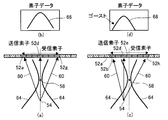
- (A) And (c) is explanatory drawing in the case of transmitting an actual ultrasonic beam from the element directly above the reflection point of the subject and the element not directly above, respectively, (b) and (d) It is explanatory drawing which shows the element data obtained, respectively.
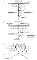
- (A) And (b) is explanatory drawing explaining the distance of the transmission path
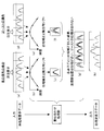
- (A), (b) and (c) and (d), (e) and (f) are respectively the element data obtained by a plurality of elements in the case of a true signal and the case of a ghost, their delay time and It is explanatory drawing which shows the superimposition state of element data, (g) And (h) is explanatory drawing which shows the superimposition state of the element data corresponding to a some element, respectively, and its result.
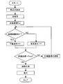
- 3 is a flowchart for explaining the operation of the ultrasonic inspection apparatus shown in FIG. 1.
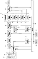
- FIG. 1 is a block diagram conceptually showing an embodiment of the configuration of the ultrasonic inspection apparatus of the present invention.
- the ultrasonic inspection apparatus 10 includes an ultrasonic probe 12, a transmission unit 14 and a reception unit 16 connected to the ultrasonic probe 12, an A / D conversion unit 18, and an element data storage unit 20.
- a position determination unit 94 and a focus setting unit 96 are provided.
- the ultrasonic probe (ultrasonic probe) 12 has a transducer array 36 used in a normal ultrasonic inspection apparatus.
- the transducer array 36 includes a plurality of elements arranged in a one-dimensional or two-dimensional array, that is, ultrasonic transducers. These ultrasonic transducers transmit an ultrasonic beam to a subject in accordance with a drive signal supplied from the transmission unit 14 when an ultrasonic image of an object to be examined (hereinafter referred to as a subject) is captured. An ultrasonic echo from the specimen is received and a reception signal (analog element signal) is output.
- each of the predetermined number of ultrasonic transducers forming one set among the plurality of ultrasonic transducers of the transducer array 36 generates each component of one ultrasonic beam, and sets a predetermined number of ultrasonic transducers.
- the ultrasonic transducer generates one ultrasonic beam that is transmitted to the subject.
- Each ultrasonic transducer is, for example, a piezoelectric ceramic represented by PZT (lead zirconate titanate), a polymer piezoelectric element represented by PVDF (polyvinylidene fluoride), or PMN-PT (magnesium niobate / lead titanate). It is constituted by an element in which electrodes are formed at both ends of a piezoelectric body made of a piezoelectric single crystal or the like typified by a solid solution, that is, a vibrator.
- PZT lead zirconate titanate
- PVDF polymer piezoelectric element represented by PVDF (polyvinylidene fluoride)
- PMN-PT magnesium niobate / lead titanate
- each vibrator When a pulsed or continuous wave voltage is applied to the electrodes of such a vibrator, the piezoelectric material expands and contracts, and pulse or continuous wave ultrasonic waves are generated from the respective vibrators, and the synthesis of these ultrasonic waves. As a result, an ultrasonic beam is formed.
- each vibrator expands and contracts by receiving propagating ultrasonic waves to generate electric signals, and these electric signals are output as ultrasonic reception signals (analog element signals).
- the focus setting unit 96 transmits a plurality of transmission lines and each transmission when the transducer array 36 transmits an ultrasonic beam according to transmission focus information (focus position information) input from the operation unit 32. Set the focal position on the line. Specifically, like the conventional ultrasonic inspection apparatus, the focus setting unit 96 sets the display area (inspection range), the depth (depth), and the like input from the operation unit 32, and the transducer array 36. A plurality of transmission lines for transmitting the ultrasonic beam are set according to information such as the arrangement interval of the transducers, and the position that becomes the focal point of the ultrasonic beam is automatically set on each transmission line. Note that the focus setting unit 96 may set the focus position from the focus position information directly input by the operator from the operation unit 32.
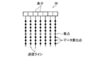
- FIG. 2 shows an example of the set focal position.
- one transmission line is set on the same line as each element corresponding to each element (ultrasonic transducer) of the transducer array 36.
- one focal position is set at the same depth on each transmission line. Information on the set focal position is supplied to the transmission unit 14, the calculation point position determination unit 94, and the control unit 30.
- the transmission unit 14 includes, for example, a plurality of pulsars, and based on the transmission delay pattern selected according to the control signal from the control unit 30 and the focus position information from the focus setting unit 96, the transducer array 36.
- An ultrasonic beam component transmitted from a set of a predetermined number of ultrasonic transducers (hereinafter referred to as ultrasonic elements) forms one ultrasonic beam and forms a focal point at a set focal position.
- the delay amount of the drive signal is adjusted and supplied to a plurality of ultrasonic elements forming a set.
- the transmission unit 14 uses an ultrasonic element on the same line as the set transmission line as a central element, and the central element and a plurality of adjacent ultrasonic elements are combined into a set of transmission elements (transmission apertures). ), A drive signal is supplied so as to transmit an ultrasonic beam that forms a focal point at the set focal position.
- the receiving unit 16 In response to a control signal from the control unit 30, the receiving unit 16 causes the transducer array 36 to transmit the ultrasonic echo generated by the interaction between the ultrasonic beam transmitted from the transducer array 36 and the subject. Received and output received signals, ie, analog element signals for each ultrasonic element are amplified and output. Specifically, the receiving unit 16 uses the central element when the corresponding ultrasonic beam is transmitted and a plurality of ultrasonic elements adjacent to the central element as a set of receiving elements (reception apertures). The ultrasonic echoes reflected within are received.
- the reception unit 16 includes a plurality of analog element signals received by a plurality of ultrasonic elements, corresponding to one transmission of the ultrasonic beam, and includes information on the received ultrasonic elements and information on reception times.
- One analog element data (first element data) is output. That is, the element data (first element data) is data representing the intensity of the received signal with respect to the position of the element and the reception time (see FIG. 4 and the like).
- the receiving unit 16 receives an ultrasonic echo and outputs analog element data every time the transmitting unit 14 transmits one ultrasonic beam. Therefore, the transmitter 14 outputs a plurality of analog element data corresponding to each transmission by transmitting the ultrasonic beam a plurality of times in accordance with the set transmission line and focus position.
- the receiver 16 supplies analog element data to the A / D converter 18.
- the A / D converter 18 is connected to the receiver 16 and converts the analog element data supplied from the receiver 16 into digital element data (first element data).
- the A / D converter 18 supplies the A / D converted digital element data to the element data storage unit 20.
- the element data storage unit 20 sequentially stores digital element data output from the A / D conversion unit 18.
- the element data storage unit 20 stores information on the frame rate input from the control unit 30 (for example, parameters indicating the depth of the reflection position of the ultrasonic wave, the density of the scanning line, and the visual field width) in the digital element data ( Hereinafter, the data is stored in association with element data).
- the element data storage unit 20 stores and holds two or more element data obtained by transmitting and receiving ultrasonic waves to different transmission lines based on control by the control unit 30.
- the calculation point setting unit 92 sets positions of a plurality of data calculation points for processing element data in the element data processing unit 22 described later based on the imaging condition input from the operation unit 32. Specifically, the calculation point setting unit 92 sets the display area (inspection range), depth (depth), image quality, and the like input from the operation unit 32, and the transmission line and focus set by the focus setting unit 96. A plurality of data calculation points (sampling points) for processing the element data are set on each transmission line based on the position information and information such as the arrangement interval of the transducers in the transducer array 36.
- FIG. 2 shows an example of the set sampling points.
- a transmission line is set for each element of the transducer array 36, and a plurality of sampling points are arranged at equal intervals on each transmission line.
- a sampling point is also set at the focal position.
- the sampling points are arranged at equal intervals.
- the present invention is not limited to this, and the arrangement intervals of the sampling points may be different depending on the depth. For example, in the depth region of interest, the sampling point arrangement interval may be close.
- the set sampling point position information is supplied to the calculation point position determination unit 94.
- the calculation point position determination unit 94 is a part that determines whether the distance from the focal point is within a predetermined range for each sampling point (data calculation point) set by the calculation point setting unit 92. Specifically, the calculation point position determination unit 94 calculates the distance from the focal point on the same transmission line for each sampling point set by the calculation point setting unit 92, and whether the calculated distance is within a predetermined threshold. It is determined whether or not it is in the vicinity of the focal point.
- the threshold value for determining the distance from the focal point is not particularly limited, but may be set according to the transmission conditions such as the numerical aperture and the F value where the convergence of the focal point changes.
- the thickness is preferably 5 to 30 mm. Furthermore, when the F value is small and the focus convergence is high, the range is narrowed to about 5 mm. Conversely, when the F value is large and the focus convergence is low, the range is expanded to about 30 mm. May be set. Further, the threshold value may be changeable from the operation unit 32.
- one focus is set on one transmission line.
- the present invention is not limited to this, and a plurality of focal points may be set on one transmission line.
- it may be determined whether the distance from the closest focal point is within a predetermined threshold.
- the depth of focus set is the same for all transmission lines, but the present invention is not limited to this, and the focus may be set to a different depth for each transmission line.
- the configuration is not limited to determining whether the distance to the focal point on the same transmission line is within a threshold value, and whether the distance to the closest focal point including a different transmission line is within the threshold value. May be determined.
- the calculation point position determination unit 94 supplies the determination result to the element data processing unit 22.
- the element data processing unit 22 Based on the control by the control unit 30, the element data processing unit 22 transmits element data (hereinafter also referred to as unprocessed element data) obtained by transmitting an ultrasonic beam to a transmission line where sampling points exist, Element data (unprocessed element data) corresponding to a transmission line different from the data is read from the element data storage unit 20, and based on the information on the reception time and the geometrical arrangement of the ultrasonic elements, the time and position Are corrected and overlapped to generate post-overlay element data (second element data, hereinafter referred to as processed element data), which is element data corresponding to this sampling point. That is, the element data processing unit 22 performs an overlay process on unprocessed element data, and reconstructs element data corresponding to this sampling point.
- element data hereinafter also referred to as unprocessed element data
- the element data processing unit 22 calculates a shift (delay time) in reception time between unprocessed element data to be superimposed, and the ultrasonic beam.
- a shift delay time
- the sampling point is far from the focal point according to the determination result of the calculation point position determination unit 94, assuming a plane wave, and a second mode for calculating the delay time between the unprocessed element data to be superimposed
- the delay time is calculated in the first mode, and when the sampling point is near the focal point, the delay time is calculated in the second mode and the unprocessed element data is superimposed to generate the processed element data.
- the element data processing unit 22 supplies the processed element data of each sampling point to the image generation unit 24 (phasing addition unit 38).
- the element data is superposed by assuming that the ultrasonic beam is a convergent wave according to whether or not the distance between the data calculation point and the focal point is within a predetermined range.
- the first element data is superimposed to generate second element data.
- the element data can be accurately superimposed at a position far from or near the focal point, the SN ratio can be increased and the resolution can be increased over the entire image, and the frame rate is not different from the conventional one. It is possible to obtain a sharp ultrasonic image with high resolution and optimum spatial resolution. Details of the element data processing unit 22 will be described later.
- the image generation unit 24 generates a sound ray signal (reception data) from the element data supplied from the element data processing unit 22 under the control of the control unit 30, and generates an ultrasonic image from the sound ray signal. is there.
- the image generation unit 24 includes a phasing addition unit 38, a detection processing unit 40, a DSC 42, an image creation unit 44, and an image memory 46.
- the phasing addition unit 38 selects one reception delay pattern from a plurality of reception delay patterns stored in advance according to the reception direction set in the control unit 30, and based on the selected reception delay pattern Thus, the reception focus processing is performed by adding the respective delays to the signal of each element of the element data. By this reception focus processing, reception data (sound ray signal) in which the focus of the ultrasonic echo is narrowed is generated.
- the phasing addition unit 38 supplies the received data to the detection processing unit 40.
- the detection processing unit 40 corrects attenuation according to the distance according to the depth of the reflection position of the ultrasonic wave on the reception data generated by the phasing addition unit 38, and then performs envelope detection processing to perform detection.
- B-mode image data that is tomographic image information related to the tissue in the specimen is generated.
- a DSC (digital scan converter) 48 converts (raster conversion) the B-mode image data generated by the detection processing unit 40 into image data according to a normal television signal scanning method.
- the image creation unit 44 performs various necessary image processing such as gradation processing on the B-mode image data input from the DSC 42 to create B-mode image data for use in inspection and display, and then creates the created inspection. Or display B-mode image data is output to the display control unit 26 for display or stored in the image memory 46.
- the image memory 46 temporarily stores the inspection B-mode image data created by the image creation unit 44.
- the inspection B-mode image data stored in the image memory 46 is read to the display control unit 26 for display on the display unit 28 as necessary.
- the display control unit 26 causes the display unit 28 to display an ultrasonic image based on the inspection B-mode image signal subjected to the image processing by the image creation unit 44.
- the display unit 28 includes a display device such as an LCD, for example, and displays an ultrasonic image under the control of the display control unit 26.
- the control unit 30 controls each unit of the ultrasonic inspection apparatus 10 based on a command input from the operation unit 32 by the operator.
- the control unit 30 receives various information by the operator via the operation unit 32, particularly information necessary for setting the transmission focus by the focus setting unit 96, and element data by the element data processing unit 22.
- the above-described various information input from the operation unit 32 is transmitted to the transmission unit 14, the reception unit 16, the element data storage unit 20, the element as necessary.
- the data is supplied to the data processing unit 22, the image generation unit 24, the display control unit 26, the focus setting unit 96, and the like.
- the operation unit 32 is for an operator to perform an input operation, and can be formed from a keyboard, a mouse, a trackball, a touch panel, and the like. In addition, the operation unit 32 displays various information as required by the operator, in particular, a display region (examination range) used for setting the transmission focus, a depth (depth), a transducer array 36, a position of the transmission focus, and the like. Information about the object to be used for element data processing, information about the inspection aperture of the subject, transmission aperture and reception aperture of the transducer array 36, and element data processing such as the number of overlapping element data and the overlapping processing method An input device is provided for inputting information related to the information.
- the storage unit 34 is a variety of information input from the operation unit 32, in particular, information related to the display area, depth, probe 12 (vibrator array 36), sound speed, transmission focal point position, transmission aperture, reception aperture, and the like, Information relating to element data processing such as the number of overlapping element data and the overlay processing method, etc., transmission unit 14, reception unit 16, element data storage unit 20, element data processing unit 22, image generation unit 24, display control unit 26, etc.
- Information relating to element data processing such as the number of overlapping element data and the overlay processing method, etc.
- the information required for the processing and operation of each unit controlled by the control unit 30 and the operation program and processing program for executing the processing and operation of each unit are stored.
- Hard disk, flexible disk, MO, MT Recording media such as RAM, CD-ROM, and DVD-ROM can be used.
- the element data processing unit 22, the phasing addition unit 38, the detection processing unit 40, the DSC 42, the image creation unit 44, the focus setting unit 96, the focus resetting unit 98, and the display control unit 26 include a CPU and various types of CPUs.
- the program is composed of operation programs for performing processing, but may be configured by a digital circuit.
- the element data processing unit 22 includes a delay time calculation unit 48, a mode switching unit 49, and an overlay processing unit 50.
- the mode switching unit 49 switches the mode when the delay time calculation unit 48 calculates the delay time according to the determination result of the calculation point position determination unit 94. Specifically, according to the determination result of the calculation point position determination unit 94, the mode switching unit 49 applies a delay time in a first mode to be described later for a sampling point whose distance from the focal point is larger than a predetermined threshold. For the sampling point whose distance from the focal point is within a predetermined threshold, the mode of the delay time calculation unit 48 is switched so that the delay time is calculated in the second mode described later.
- the delay time calculation unit 48 examines the plurality of ultrasonic elements and the subject of the transducer array 36 of the probe 12 input from the operation unit 32 or input from the operation unit 32 and stored in the storage unit 34. Information on the sound velocity of the target area, information on the transmission aperture and reception aperture of the transducer array 36, and information on the transmission focus set by the focus setting unit 96 is acquired in advance, and an ultrasonic beam is formed and transmitted. Based on the geometric arrangement of the ultrasonic element (transmitting element) of the opening and the ultrasonic element (receiving element) of the receiving opening that receives an ultrasonic echo from the subject by the ultrasonic beam, The delay time of the element data received by each ultrasonic element is calculated.
- the delay time calculation unit 48 uses a first mode (convergent wave mode) for obtaining a delay time from the transmission path of the ultrasonic beam when the ultrasonic beam is modeled by considering it as a convergent wave, and the ultrasonic beam.
- a second mode (plane wave mode) for obtaining a delay time from the transmission path of the ultrasonic beam when modeled as a plane wave is provided, and the mode switching unit 49 switches the mode for each sampling point to calculate the delay time. To do. Details of the convergent wave mode and the plane wave mode will be described later.
- the superposition processing unit 50 inputs the number of element data to be superposed, the superposition processing method, etc. input from the operation unit 32 or input from the operation unit 32 and stored in the storage unit 34 for each sampling point. Based on the information related to the element data processing, two or more element data obtained by transmitting ultrasonic beams to different transmission lines stored and held by the element data storage unit 20 are read out, and an overlay process is performed. Paying attention to a predetermined point (sampling point) on the power line of interest, based on the delay time calculated by the delay time calculation unit 48, two or more unprocessed element data are received on the reception time, that is, the time is matched. And the absolute position of the received element of the probe is matched and superimposed to generate processed data.
- an ultrasonic beam (hereinafter simply referred to as a transmission beam) is transmitted to an object from an ultrasonic element (hereinafter simply referred to as a transmission element) forming a transmission aperture of the transducer array 36 of the ultrasonic probe 12, and between the objects.
- element data unprocessed element data
- an ultrasonic element (hereinafter simply referred to as a receiving element) that forms a receiving aperture of the transducer array 36.
- transmission lines are set corresponding to each ultrasonic element in a direction orthogonal to the arrangement direction of the ultrasonic elements, and one focal position is set for each transmission line. It is a figure which shows typically each ultrasonic element, ultrasonic beam, focal position, and ultrasonic echo when set.
- three ultrasonic elements 52c to 52e and 52d to 52f are used as transmitting elements, respectively, and seven ultrasonic elements (hereinafter also simply referred to as elements) 52a to 52g are used.
- the transmission beam 56 to be transmitted to the inspection target area including the reflection point 54 is ideally narrowed to an element interval or less.
- the focal point 58 of the transmission beam 56 is 4d and is in a straight line connecting the reflection point 54, the transmitted beam 56, since it is transmitted to the reflection point 54, the ultrasonic echoes are generated to be reflected from the reflection point 54.
- the ultrasonic echoes from the reflection point 54 are received by the receiving elements 52a to 52g through the receiving path 60 spreading at a predetermined angle, and the element data 62 as shown in FIG. 4B is obtained by the receiving elements 52a to 52g. Will be.
- the transmission beam 56 is transmitted to the transmission line corresponding to the element 52e, and the ultrasonic echoes are received by the reception elements 52b to 52h.
- the reflection point 54 does not exist on the transmission direction of the transmission beam 56, that is, on the straight line connecting the transmission element 52 e and the focal point 58 (on the transmission line). Not sent. For this reason, the ultrasonic echo reflected from the reflection point 54 is not generated, and the receiving elements 52b to 52h do not receive the ultrasonic echo. Therefore, as shown in FIG. It becomes the data of.
- the actual transmission beam 64 is wider than the element spacing.
- the transmission beam 64 is transmitted to the transmission line corresponding to the element 52d, with the elements 52c to 52e having the element 52d immediately above the reflection point 54 as the central element.
- the transmission beam 56 is wide, its focal point 58 is on a straight line connecting the element 54d and the reflection point 54, and the transmission beam 64 is reflected. Reflected at point 54, an ultrasonic echo is generated.
- an ultrasonic echo is generated.
- the ultrasonic echo from the reflection point 54 is received by the receiving elements 52a to 52g through the receiving path 60 spreading to a predetermined angle, and is received by the receiving elements 52a to 52g.
- True element data 66 as shown in FIG. 5B is obtained.
- the center of the transmitting element is shifted by one element from the reflection point 54 in the element direction (right direction in the figure).
- the transmission beam 64 is transmitted to the transmission line corresponding to the element 52e, with the elements 52d to 52f having the element 52e adjacent to the element 52d immediately above the reflection point 54 as the central element as transmission elements.
- the transmission beam 64 is wide, so that the reflection point 54 does not exist on the transmission direction, that is, on the straight line connecting the transmitting element 52e and the focal point 58. However, the transmission beam 64 is transmitted to the reflection point 54.
- the ultrasonic echo reflected from the reflection point 54 is received by the receiving elements 52b to 52h through the receiving path 60 spread at a predetermined angle, and as shown in FIG. 5D by the receiving elements 52b to 52h.
- Element data 68 affected by the reflection point is obtained.
- an acoustic ray signal is generated from element data 68 (hereinafter also referred to as ghost element data) affected by a reflection point other than on the transmission line
- an ultrasonic image is generated, which corresponds to the element 52e.
- An image of a reflection point that does not actually exist is reproduced in the line image, so-called ghost is generated, and this causes a decrease in the accuracy of the ultrasonic image.
- the transmission beam 64 shown in FIG. 5C is transmitted from the transmission element 52e through the focal point 58 to the reflection point 54, and the ultrasonic echo from the reflection point 54 is received from the reception elements 52b to 52h.
- the sum (propagation distance) with the path is such that the transmission beam 64 shown in FIG. 5A reaches the reflection point 54 from the transmission element 52 d via the focal point 58 and the reflected ultrasonic echo from the reflection point 54. It becomes longer than the sum (propagation distance) with the reception path reaching each of the receiving elements 52a to 52g. Therefore, the ghost element data 68 as shown in FIG. 5D is delayed with respect to the true element data 66 as shown in FIG. 5B.
- the geometrical arrangement of the sampling point on the transmission line of interest and the central element corresponding to each transmission line causes the transmission line to exceed the transmission line of interest.
- Element data obtained by transmitting / receiving sound waves hereinafter also referred to as “target element data”
- element data obtained by transmitting / receiving ultrasonic waves to a transmission line different from the target transmission line hereinafter, “non-target element data”.
- the shape of the ultrasonic probe 12 (vibrator array 36) (element spacing, linear, convex, etc.), the sound velocity of the examination region of the subject, the focal position, the transmission aperture, the reception aperture, etc.
- Information is necessary, and in the delay time calculation unit 48, information on the focal position set by the focus setting unit 96, information on the sampling point set by the calculation point setting unit 92, input by the operation unit 32, or storage The information stored in the unit 34 is acquired and the delay time is calculated.
- the delay time is calculated from, for example, the transmission path and sampling point of the transmission beam from the transmission element to the sampling point through the focal point, which is calculated from the geometry of the transmission element, the focus of the ultrasonic beam, the sampling point, and the reception element. It can be calculated from the difference between the total length (propagation distance) of the reception path of the reflected signal reaching the reception element and the propagation time calculated by the sound speed.
- the delay time calculation unit 48 regards the ultrasonic beam as a convergent wave, that is, transmits from the transmission element to the sampling point through the focal point with the focal point as a point (point sound source).
- a convergent wave mode for calculating a delay time by calculating a total length (propagation distance) of a reflected signal reception path from a beam transmission path and a sampling point to a receiving element, and regarding an ultrasonic beam as a plane wave, and a plane wave mode for calculating the delay time by obtaining the total length of the reception path.
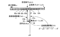
- the convergent wave mode will be described with reference to FIGS. 6 (a) and 6 (b).
- the transmission beam once reaches the focal point (converges), then proceeds to the sampling point, and is modeled as being reflected at the sampling point to calculate the transmission path.
- the lengths of the transmission path of the transmission beam and the reception path of the ultrasonic echo for each of the target element data and the non-target element data are obtained. be able to.
- FIG. 6A and FIG. 6B for the sake of explanation, it is assumed that there is a reflection point 54 at the sampling point on the target transmission line.
- the transmission elements 52c to 52e in the case of element-of-interest data, that is, when the transmission line of interest (transmission line at the sampling point) matches the transmission line that transmitted the ultrasonic beam, the transmission elements 52c to 52e. And the central elements of the receiving elements 52a to 52g are coincident with each other, and the focal point 58 and the reflection point 54 are disposed directly below the central element.
- the position of the element 52d directly above the reflection point 54 is the coordinate (x0, 0) on the xy two-dimensional coordinate, the element interval is Le, the position of the focal point 58 is the coordinate (x0, df), and the position of the reflection point 54 is the coordinate ( x0, z), the position of the transmitting element 52d is also in the same coordinate (x0, 0) as the element 52d immediately above the reflecting point 54, and the transmission beam transmitted from the transmitting element 52d through the focal point 58 to the reflecting point 54 is transmitted.
- non-target element data that is, when an ultrasonic beam is transmitted to a transmission line (transmission line different from the sampling point) adjacent to the target transmission line
- the positions of the central elements 52d to 52f are shifted laterally by one element (x direction: right direction in the figure) with respect to the reflection point 54 (sampling point), and the focal point 58 is arranged directly below the central element 52e.
- the reflection point 54 is disposed directly below the receiving element 52d.
- the position of the receiving element 52d immediately above the reflection point 54 is set to the coordinates (x0, 0) on the xy two-dimensional coordinates, the element interval is Le, and the position of the reflection point 54 is the coordinates (x0).
- the position of the transmitting element 52e is the coordinate (x0 + Le, 0)
- the position of the focal point 58 is the coordinate (x0 + Le, df).
- the value obtained by dividing the ultrasonic propagation distance Lua by the sum of the distance Lta of the transmission path 61 and the distance Lra of the reception path 60 obtained by the geometrical arrangement shown in FIG. This is the propagation time between the ultrasonic element and the sampling point when ultrasonic waves are transmitted and received for acquisition.
- the value obtained by dividing the ultrasonic propagation distance Lub which is the sum of the distance Ltb of the transmission path 61 and the distance Lrb of the reception path 60 obtained by the geometric arrangement shown in FIG. This is the propagation time between the ultrasonic element and the sampling point when ultrasonic waves are transmitted and received on the transmission line adjacent to the transmission line.
- the calculation of the delay time is based on the propagation time of the ultrasonic wave between the ultrasonic element and the sampling point when acquiring the element-of-interest data and between the ultrasonic element and the sampling point when acquiring the non-target element data.
- the delay time is obtained from the difference in ultrasonic propagation time.
- the transmission path 61 is a model that passes through the focal point 58, but the present invention is not limited to this, for example, it passes through the focal point 58. Alternatively, a route that directly reaches the reflection point 54 may be used.
- the transmission beam does not converge to the focal point, but travels as a plane wave to the sampling point, and is modeled as being reflected at the sampling point to calculate the transmission path.
- the plane wave mode as shown in FIG. 7, the length of the transmission path of the transmission beam of the non-target element data and the reception path of the ultrasonic echo can be obtained. Note that the method of obtaining the transmission path and the reception path in the case of the element of interest data is the same as in the convergent wave mode, and thus description thereof is omitted. In FIG. 7, for the sake of explanation, it is assumed that there is a reflection point 54 at the sampling point.
- the position of the central element of the transmitting elements 52d to 52f is one element lateral to the reflection point 54 (sampling point) (x direction: in the figure).
- the focal point 58 is disposed directly below the central element 52e
- the reflection point 54 is disposed directly below the receiving element 52d.
- the position of the receiving element 52d immediately above the reflection point 54 is set to the coordinates (x0, 0) on the xy two-dimensional coordinates, the element interval is Le, and the position of the reflection point 54 is the coordinates (x0, z).
- the position of the transmitting element 52e is coordinates (x0 + Le, 0), and the position of the focal point 58 is coordinates (x0 + Le, df).
- the transmission beams transmitted from the plurality of transmission elements 52d to 52f reach the reflection point 54 as plane waves. That is, the path from the focal point 58 to the reflection point 54 is considered as a path projected on the z axis. Therefore, in the case of a linear probe as shown in FIG. 7, the length Ltb of the transmission path is equal to the depth z of the reflection point 54.
- the length of the transmission path is calculated with the focal point as the ultrasonic beam as a convergent wave, but the actual focal point of the ultrasonic beam is converged so as to be regarded as a point. It has no finite width. Therefore, when the length of the transmission path is calculated in the convergent wave mode for the sampling point near the focal point, it becomes longer than the length of the actual transmission path, and the delay time is calculated from the calculated length of the transmission path. The difference from the actual delay time increases, and the accuracy of superimposing element data also decreases. Therefore, for the sampling points near the focal point, the delay time is calculated by obtaining the length of the transmission path in the plane wave mode, so that it is possible to prevent the accuracy of superimposing unprocessed element data from being lowered. .
- the delay time is calculated by using the delay time at the element 52 located immediately below the sampling point as a representative value in the transmission / reception of ultrasonic waves with a certain element as the central element. This is used as the delay time of all elements in this transmission / reception.
- the present invention is not limited to this.
- the reception path distance Lrb of the element 52c, the element 52b, or the like whose position in the x direction is different from the sampling point, that is, the element 52d immediately below is the element directly below.
- Lrb ⁇ ⁇ (n ⁇ Le) 2 + z 2 ⁇ .
- the geometric models in FIGS. 6A, 6B, and 7 are cases of a linear probe.
- the geometric model is not limited to this, and in other probes, a convergent wave mode and a plane wave mode are used depending on the shape of the probe.
- Each can perform similar geometric calculations.
- a geometric model can be set from the radius of the probe and the angle between the elements, and the calculation can be performed in the same way.
- steer transmission a geometric model (not shown) that considers information such as the transmission angle is used, and the attention element data and the surrounding non- attention element data are determined from the positional relationship between the transmission element and the sampling point. The delay time can be calculated.
- FIG. 6C shows true element data 66 which is element data when there is a reflection point on the transmission line in the center, and element data 68 of a ghost in which a ghost is generated due to the influence of the reflection point on both sides.
- FIG. 6D shows the delay of the ghost element data 68 which is the non-target element data when the central true element data 66 obtained from this geometric calculation is the target element data.
- An example of time is shown. It is shown that when the true element data 66 is the target element data, the ghost element data 68 is symmetrically delayed. In this way, the delay time calculated by the delay time calculation unit 48 of the element data processing unit 22 can also be used for delay correction in the phasing addition unit 38.
- the delay time calculation unit is thus performed for the sampling points for which the calculation point position determination unit 94 determines that the distance from the transmission focus is outside a predetermined range.
- the delay time calculated in 48 the target element data of the target transmission line and the non-target element data which is the element data of the transmission line in the vicinity thereof are superimposed.
- the convergence wave mode and the plane wave mode differ only in the delay time calculation method and the overlay process is the same. Therefore, in the following explanation, the overlap process using the delay time calculated in the convergent wave mode is described. explain.
- the superposition processing in the superposition processing unit 50 information on the number of superposition element data and the superposition processing method at the time of superposition is necessary, but these may be input in advance by the operation unit 32. Alternatively, it may be stored in the storage unit 34.
- FIGS. 8A to 8H show a specific example of superposition processing performed by the superposition processing unit 50 when the number of element data is five and the number of superposition element data is three.
- FIG. 8 (a) shows five element data obtained by performing ultrasonic transmission / reception side by side on a transmission line having five adjacent elements as central elements, respectively.
- FIG. It shows a state in which an ultrasonic beam is transmitted and a reflected signal is received.
- the horizontal axis of each element data represents a receiving element, and the respective element data are displayed with the center element at the time of transmission of the ultrasonic beam as the center.
- the vertical axis represents the reception time.
- the element data in the middle there is a reflection point immediately below the element at the center of the element data (element at the center of the receiving element), that is, the center element at the time of transmission (transmitting element).
- a reflection signal (ultrasonic echo) from the reflection point is received. That is, this reflected signal is a true signal, and the element data in the middle represents the true element data.
- the transmission element of the middle element data A reflected signal, i.e., a ghost, which is generated when an ultrasonic beam hits a reflection point existing directly below, is reflected. Since the propagation time of the ultrasonic wave to the reflection point becomes longer as the ghost is away from the true signal, the reception time is delayed as compared with the true element data.
- the position of the receiving element where the reflected signal from the reflection point is first received is the element immediately above the reflection point, but the horizontal axis of the element data is centered on the central element at the time of transmitting the ultrasonic beam.
- the center element is shifted by one element for each element data, that is, the transmission line is shifted by one line
- the absolute position of the element is shifted by one element in each element data. That is, in the middle element data, the receiving element from which the reflected signal from the reflection point is received first is the middle element, but the element data on both sides is shifted by one element from the middle element data.
- the element data is shifted one element to the left, and the left element data is shifted one element to the right.
- the element data at both ends are shifted by two elements from the middle element data, the leftmost element data is shifted by two elements to the left, and the leftmost element data is shifted by two elements to the right.
- the ghost signal is not only delayed in reception time with respect to the true signal, but also deviated from the direction of the receiving element.
- the overlay processing unit 50 uses the delay time shown in FIG. 8B to set the element data in the middle as the noticed element data.
- the delay time correction is performed on the three element data, and the amount of deviation between the center element (target element) corresponding to the transmission line of the target element data and each center element, in the illustrated example, one element on both sides.
- the data is shifted in the direction, that is, the unprocessed element data corresponding to the three transmission lines is superposed with the phase being matched to obtain one overlap-processed element data corresponding to a predetermined sampling point of the target transmission line.
- FIG. 8C shows the superposed element data obtained at the sampling point where the reflection point is on the same line. Since the element data of the target element shown in FIG. 8A is element data of a true signal, the delay time correction and the lateral shift are performed on the unprocessed element data of the adjacent elements on both sides of the target element. When matching is performed, as shown in FIG. 8C, the unprocessed element data of the adjacent element and the unprocessed element data of the target element overlap each other at the high luminance position because the phases match. Therefore, when these element data are added, for example, the element data value shows a large value (high luminance value), and for example, even if an average value is obtained by averaging, an emphasized value (high luminance value) is shown.
- FIG. 8D shows the same element data group as FIG. 8A, but the element data on the left side of the middle element data, that is, the ghost element data is set as the element data of interest, that is, An example in which processing is performed on a sampling point on the transmission line on the left adjacent to the middle is shown.
- FIG. 8E shows an example of the delay time of the reception time when the center left adjacent element is the target element. Since FIG. 8A and FIG. 8D are the same element data group, the delay time shown in FIG. 8E is the same as FIG. 8B except for the element of interest.
- the overlay processing unit 50 uses the delay time shown in FIG.
- FIG. 8F shows superposed element data obtained by sampling points having reflection points on adjacent lines. Since the element data of the target element shown in FIG. 8D is ghost element data, phase adjustment is performed by performing delay time correction and lateral shift on the unprocessed element data of adjacent elements on both sides of the target element. Even if it is performed, as shown in FIG. 8F, the unprocessed element data of the adjacent element and the unprocessed element data of the target element do not overlap each other because the phases do not match. For this reason, even if these three element data are added, for example, since the phases are not matched, signals that are inverted in phase cancel each other out, so the added value does not increase. When the average value is obtained, a small value is shown.
- FIG. 8 (h) shows the result of, for example, addition processing or averaging processing as overlay processing shown in (g).
- FIG. 8H in the transmission line of interest when the coordinates of the central element of the transmission element shown in FIG. 8A coincide with the reflection point (when there is a reflection point on the transmission line).
- the element data of the true signal is obtained as superposed processed element data having a high luminance value, and the ghost element data is added to the element data whose phases are not in phase with each other in all four elements on both sides.
- the ghost superimposed element data is smaller than the superimposed element data having a high luminance value whose value is the element data of the true signal.
- the influence of the ghost element data on the element data of the true signal can be reduced, or the influence can be reduced to the extent that the influence can be ignored.
- an average value or a median value may be taken, or addition may be performed after multiplying coefficients.
- taking an average value or median value is thought to correspond to applying an averaging filter or median filter at the element data level, but is performed by normal image processing instead of the averaging filter or median filter.
- An inverse filter or the like may also be applied.
- the element data to be superimposed are compared, and if they are similar, the maximum value is taken, if not, the average value is taken, and if there is a distribution bias, the intermediate value is taken.
- the overlay process may be changed based on the feature amount of each element data to be superimposed.
- the number of element data to be superimposed is matched to the extent of the beam width of the ultrasonic beam. Therefore, when the beam width changes depending on the depth, the number of overlapping element data may be changed depending on the depth. Further, since the beam width depends on the transmission numerical aperture, the number of overlapping element data may be changed according to the transmission numerical aperture. Alternatively, the number of overlapping element data may be changed based on a feature quantity such as the luminance value of the image, or the optimum number of overlapping element data is selected from images created by changing the number of overlapping element data. May be. As a result of the superposition, as described above, the signal phase matches in the element data of the true signal, but the signal phase does not match in the ghost.
- the present invention is a first mode in which element data is superimposed on the assumption that an ultrasonic beam is a convergent wave, depending on whether or not the distance between the sampling point and the focal point is within a predetermined range.
- the second mode in which element data is superimposed on the assumption of a plane wave, and the second element data is generated by superimposing the first element data. Specifically, when the sampling point is determined that the distance from the focal point is outside a predetermined range, that is, when the sampling point is far from the focal point, the ultrasonic propagation distance calculated from the ultrasonic beam as a convergent wave is used.
- a shift in reception time between unprocessed element data (first element data) to be superimposed, that is, a delay time is calculated, and a plurality of values are calculated based on information on the delay time and the geometrical arrangement of elements.
- the unprocessed element data is synthesized, and new processed element data (second element data) corresponding to the sampling point is generated.
- the delay time is calculated from the propagation distance of the ultrasonic wave calculated by regarding the ultrasonic beam as a plane wave. Then, based on the information on the delay time and the geometric arrangement of the elements, a plurality of unprocessed element data is synthesized to generate new processed element data corresponding to the sampling point.
- the ultrasonic inspection apparatus of the present invention can improve the S / N ratio and resolution of the entire image, and is sharp with an optimum spatial resolution at a high resolution with a frame rate unchanged from the conventional one. An ultrasonic image can be obtained.
- the optimum sound speed can be obtained with high accuracy even when the optimum sound speed for each region in the inspection target area is obtained using the element data.
- FIG. 9 is a flowchart for explaining the operation of the ultrasonic inspection apparatus shown in FIG.
- the focus setting unit 96 sets the focus position according to the information input from the operation unit 32, and supplies the set focus position information to the transmission unit 14 and the calculation point position determination unit 94.
- the calculation point setting unit 92 sets data calculation points (sampling points) according to the information input from the operation unit 32 and supplies the data calculation points to the calculation point position determination unit 94.
- the calculation point position determination unit 94 determines whether the distance from the focal point is within a predetermined range for each sampling point based on the supplied sampling point information and focal point position information, and the determination result is obtained as element data. This is supplied to the processing unit 22.
- an ultrasonic beam is transmitted from the transducer array 36 according to the drive signal supplied from the transmission unit 14, and the ultrasonic wave from the subject is transmitted.
- the transducer array 36 receives the echo and outputs an analog element signal as a reception signal.
- the transmission unit 14 drives the transducer array 36 so as to transmit an ultrasonic beam that forms a focal point at the focal position supplied from the focal point setting unit 96.
- the receiving unit 16 outputs an analog element signal output from each element as one analog element data, and supplies it to the A / D converter 18.
- the A / D conversion unit 18 converts analog element data into digital element data, supplies the element data to the element data storage unit 20, and stores and holds the data.
- the element data processing unit 22 delays the unprocessed element data of the target transmission line and the unprocessed element data of the peripheral transmission lines (for example, FIG. 8B).
- the geometrical arrangement of the transmitting element, the focal point, the reflecting point, and the receiving element, and the input object set in advance For each sampling point, the geometrical arrangement of the transmitting element, the focal point, the reflecting point, and the receiving element, and the input object set in advance. Calculation is performed from the sound velocity of the examination target region of the specimen (for example, calculation is performed using the geometric model in FIG. 6).
- the element data processing unit 22 sequentially performs processing according to the determination result of the calculation point position determination unit 94 for each sampling point (calculation coordinates Pst to Pend).
- the delay time is calculated in the convergent wave mode, and a plurality of unprocessed element data including the unprocessed element data of the transmission line corresponding to the sampling point is obtained.
- the element data to be read from the element data storage unit 20 and processed is set as the element data of interest, and the overlap element 50 (FIG. 3) uses the delay time calculated by the delay time calculator 48 and the element data of interest.
- the processed element data is obtained by superposing the unprocessed element data (non-target element data) of the peripheral transmission lines in phase with each other.
- a plurality of unprocessed element data including the unprocessed element data of the transmission line corresponding to the sampling point by calculating the delay time in the plane wave mode Is read from the element data storage unit 20 the element data to be processed is set as the element data of interest, and the overlap element 50 (FIG. 3) uses the delay time calculated by the delay time calculation unit 48,
- the processed element data is obtained by superimposing and superimposing unprocessed element data (non-target element data) on the surrounding transmission lines.
- the processed element data in which the true signal is emphasized and the ghost signal is attenuated is obtained.
- the element data thus obtained is supplied to the phasing adder 38 of the image generator 24.
- the phasing addition unit 38 of the image generation unit 24 performs reception focus processing on the processed element data to generate reception data (sound ray signal), and supplies it to the detection processing unit 40.
- the detection processing unit 40 processes the sound ray signal and generates a B-mode image signal.
- the DSC 42 performs raster conversion on the B-mode image signal, and the image creation unit 44 performs image processing to generate an ultrasonic image.
- the generated ultrasonic image is stored in the image memory 46, and the ultrasonic image is displayed on the display unit 28 by the display control unit 26.
- the ultrasonic inspection apparatus 10 of the present invention superimposes element data by assuming that the ultrasonic beam is a convergent wave, depending on whether the distance between the sampling point and the focal point is within a predetermined range.
- the first element data is superimposed to generate second element data.
- the ultrasonic inspection apparatus of the present invention can improve the S / N ratio and resolution of the entire image, and is sharp with an optimum spatial resolution at a high resolution with a frame rate unchanged from the conventional one. An ultrasonic image can be obtained.
- the optimum sound speed can be obtained with high accuracy even when the optimum sound speed for each region in the inspection target area is obtained using the element data.
- the element data to be superimposed on the target element data is the element data of the transmission line adjacent to the transmission line of the target element data.
- the present invention is not limited to this. Any transmission line different from the transmission line may be used.
- the element data to be superimposed on the element data of interest is preferably element data of an adjacent transmission line or a nearby transmission line.
- the element data to be superimposed on the element data of interest is acquired by transmitting / receiving ultrasonic waves with the transmission line symmetrical about the transmission line of the element of interest data, that is, the element symmetrical about the element of interest as the central element.
- Element data is preferred.
- the delay time is calculated in the convergent wave mode.
- the delay time is calculated in the plane wave mode.
- the delay time is calculated in the convergent wave mode when the sampling point is far from the focal point, and the delay time is calculated in the plane wave mode when the sampling point is near the focal point.
- the delay time may be calculated by combining the mode and the plane wave mode.
- the delay time is calculated in the convergent wave mode, and when the distance is equal to or smaller than the second threshold smaller than the first threshold,
- the delay time calculated in the convergent wave mode and the delay time calculated in the plane wave mode are set to the distance from the focal point.
- the delay time may be calculated by weighting according to the above and averaging.
- the length of the transmission path (delay time) is calculated in the plane wave mode at the focal position, the length of the transmission path is calculated in the convergent wave mode at a position away from the focal point by a certain distance or more, and at the intermediate position, The length of the transmission path in which the plane wave mode and the convergent wave mode are weighted averaged is calculated. Thereby, it is possible to prevent discontinuities from occurring at the switching position between the convergent wave mode and the plane wave mode, and a smoother image can be obtained.
- the processing in the element data processing unit 22 (delay time calculation unit 48) is switched between the convergent wave mode and the plane wave mode according to the distance between the sampling point and the focal point.
- the present invention is not limited to this, the first image is generated using processed element data processed in the convergent wave mode at all sampling points, and processed in the plane wave mode at all sampling points.
- a second image is generated using the processed element data, and a new image is generated by combining the first image at a position far from the focus and the second image near the focus according to the distance from the focus. You may make it do.
- the ultrasonic beam is transmitted in a direction orthogonal to the arrangement direction of the ultrasonic elements.
- the present invention is not limited to this, and is inclined with respect to the arrangement direction of the ultrasonic elements. It is good also as a structure which transmits an ultrasonic beam in the direction (steer) which is doing.
- the said Example although it was set as the structure with which 1 set of transmission elements (transmission opening) and transmission of one ultrasonic beam respond
- the center of the transmitting element and the center of the receiving element are the same element, but they may be different.
- the transmission numerical aperture and the reception numerical aperture are different from each other.
- the numerical aperture may be the same, and the same element as the transmission element may be used as the reception element.
- the ultrasonic inspection apparatus of the present embodiment is controlled by an ultrasonic image data generation program stored in a memory attached to a control unit (not shown). That is, the control unit reads out the ultrasound image data generation program from the memory, sets the focus and the sampling point according to the ultrasound image data generation program, and directs the subject to the subject according to the set focus.
- a first element obtained by transmitting an ultrasonic beam, receiving an ultrasonic echo reflected from the subject, selecting a mode according to the distance from the focal point at each sampling point, and receiving the selected mode
- the function of combining the data and generating the second element data is executed.
- the ultrasonic image data generation program is not limited to the one stored in the memory attached to the control unit in this way, and the ultrasonic image data generation program may be the present ultrasonic image processing such as a CD-ROM.
- the information may be recorded in a memory medium (removable medium) configured to be detachable from the apparatus, and read into the apparatus via an interface corresponding to the removable medium.
Landscapes
- Engineering & Computer Science (AREA)
- Physics & Mathematics (AREA)
- Health & Medical Sciences (AREA)
- Life Sciences & Earth Sciences (AREA)
- Radar, Positioning & Navigation (AREA)
- Remote Sensing (AREA)
- Acoustics & Sound (AREA)
- Computer Networks & Wireless Communication (AREA)
- General Physics & Mathematics (AREA)
- Nuclear Medicine, Radiotherapy & Molecular Imaging (AREA)
- Molecular Biology (AREA)
- Biophysics (AREA)
- Veterinary Medicine (AREA)
- Pathology (AREA)
- Radiology & Medical Imaging (AREA)
- Biomedical Technology (AREA)
- Heart & Thoracic Surgery (AREA)
- Medical Informatics (AREA)
- Public Health (AREA)
- Surgery (AREA)
- Animal Behavior & Ethology (AREA)
- General Health & Medical Sciences (AREA)
- Computer Vision & Pattern Recognition (AREA)
- Multimedia (AREA)
- Ultra Sonic Daignosis Equipment (AREA)
- Investigating Or Analyzing Materials By The Use Of Ultrasonic Waves (AREA)
- Gynecology & Obstetrics (AREA)
Description
本発明は、超音波ビームを送受信することにより生体内の臓器等の検査対象物の撮像を行って、検査対象物の検査や診断のために用いられる超音波画像を生成する超音波検査装置、超音波画像データ生成方法およびプログラムに関する。
従来から、医療分野において、超音波画像を利用した超音波画像診断装置等の超音波検査装置が実用化されている。一般に、この種の超音波検査装置は、複数の素子(超音波トランスデューサ)を内蔵した超音波探触子(超音波プローブ)と、この超音波探触子に接続された装置本体とを有しており、超音波探触子の複数の素子から検査対象物(被検体)に向けて超音波ビームを送信し、被検体からの超音波エコーを超音波探触子で受信して、その受信した超音波エコー信号を装置本体で電気的に処理することにより超音波画像が生成される。
超音波検査装置においては、超音波画像を生成するとき、被検体の検査対象領域、例えば、生体内の臓器やその臓器内の病巣等に探触子の複数の素子から焦点を合わせて超音波ビームを送信し、検査対象領域の反射体、例えば臓器や病巣等の表面や界面からの超音波エコーを複数の素子を介して受信しているが、同一の反射体で反射された超音波エコーを複数の素子で受信するので、送信素子から送信された超音波ビームの焦点位置に位置する反射体で反射され、送信素子で受信された超音波エコー信号に対して、同一の反射体で反射され、送信素子と異なるその他の素子で受信された超音波エコー信号は遅延することになるので、複数の素子で受信した超音波エコー信号をA/D(アナログ/デジタル)変換して素子データとした後、素子データを受信フォーカス処理して、即ち遅延補正して位相を合わせ整相加算して音線信号を生成し、こうして得られた音線信号に基づいて超音波画像を生成している。
このような超音波検査技術において、超音波画像の画質を向上させるために、複数の異なる焦点で送信した信号を足し合わせることで、従来よりも信号の質を改善することが行われている。
例えば、特許文献1には、送信用振動素子群を構成する複数個の振動素子から放射される送信超音波を送信集束点に集束させることにより仮想的な点音源を形成し、そして、この点音源から放射される送信超音波によって連続した複数の観測点から反射する受信超音波を、受信用振動素子群を構成する複数個の振動素子によって受信し、得られたチャンネル分の受信信号に対し観測点が受信集束点となるような受信整相加算を行う。更に、前記受信用振動素子群と振動素子の配列方向に順次シフトさせた送信用振動素子群の各々を用いて得られた受信信号に対しても同様の受信整相加算を行い、これら受信整相加算後の受信信号に対し各々の送信集束点から観測点までの伝搬距離の差異に起因した送信遅延を補正する送信整相加算を行う超音波診断装置が開示されている。
特許文献1では、複数の振動素子から得られた受信信号に対して受信整相加算と送信整相加算を行なうことにより被検体の深さ方向に対してほぼ一様な細いビーム幅を有した送信ビーム及び受信ビームを高精度かつ高感度で形成することができる。このため、特許文献1は、空間分解能、コントラスト分解能及びS/Nに優れた画像データの生成と表示が可能となることを開示している。
例えば、特許文献1には、送信用振動素子群を構成する複数個の振動素子から放射される送信超音波を送信集束点に集束させることにより仮想的な点音源を形成し、そして、この点音源から放射される送信超音波によって連続した複数の観測点から反射する受信超音波を、受信用振動素子群を構成する複数個の振動素子によって受信し、得られたチャンネル分の受信信号に対し観測点が受信集束点となるような受信整相加算を行う。更に、前記受信用振動素子群と振動素子の配列方向に順次シフトさせた送信用振動素子群の各々を用いて得られた受信信号に対しても同様の受信整相加算を行い、これら受信整相加算後の受信信号に対し各々の送信集束点から観測点までの伝搬距離の差異に起因した送信遅延を補正する送信整相加算を行う超音波診断装置が開示されている。
特許文献1では、複数の振動素子から得られた受信信号に対して受信整相加算と送信整相加算を行なうことにより被検体の深さ方向に対してほぼ一様な細いビーム幅を有した送信ビーム及び受信ビームを高精度かつ高感度で形成することができる。このため、特許文献1は、空間分解能、コントラスト分解能及びS/Nに優れた画像データの生成と表示が可能となることを開示している。
しかしながら、特許文献1に開示の技術では、従来技術よりも高画質な画像が得られるが、1ラインのデータを作るのに複数の送信ビームを、送信位置を変えて発生させる必要があり、従来技術よりも送信回数が増えるためフレームレートが低下し、リアルタイム性が悪くなるという問題があった。また、特許文献1では、焦点を仮想的な点音源とみなして、複数の受信信号を合成しているが、実際は、点音源とみなせるほど焦点は収束しておらず、有限の広がりを持っているため、焦点に近い領域の画像ほど、受信信号を合成した際に、データの精度が低下して、SN比や解像度が低下するという問題があった。
本発明の目的は、上記従来技術の問題点を解消し、焦点に近い領域も含めて、画像全体で、SN比を上げ、解像度を上げることができ、かつ、従来と変わらないフレームレートのまま、高い解像度で、最適な空間分解能を持つシャープな超音波画像を得ることができる超音波検査装置、超音波画像データ生成方法およびプログラムを提供することにある。
上記目的を達成するために、本発明は、超音波ビームを用いて検査対象物を検査する超音波検査装置であって、検査対象物内に複数の送信焦点を設定する焦点設定部と、超音波ビームの各成分を発生し、かつ、検査対象物によって反射された超音波エコーを受信して、受信したアナログ素子信号を出力する、複数の素子を備える探触子と、探触子に、複数の素子を用いて、焦点設定部で設定された送信焦点それぞれに対して、超音波ビームを発生させる送信部と、前記送信焦点それぞれに対する個々の超音波ビームの送信に対応して、複数の素子が受信したアナログ素子信号を受け、所定の処理を施す受信部と、受信部が処理したアナログ素子信号をA/D変換して、デジタル素子信号である第1の素子データとするAD変換部と、検査対象物内に少なくとも1つのデータ算出点を設定する算出点設定部と、算出点設定部が設定したデータ算出点それぞれについて、送信焦点までの距離が所定の閾値以下か否かを判断する算出点位置判断部と、複数の超音波ビームの送信で得られた第1の素子データを重ね合わせて、データ算出点に対応する第2の素子データを生成する素子データ処理部とを備え、素子データ処理部は、超音波ビームを収束波と想定して、複数の第1の素子データの重ね合わせを行う第1のモード、および、超音波ビームを平面波と想定して、複数の第1の素子データの重ね合わせを行う第2のモードを有し、データ算出点から送信焦点までの距離が所定の閾値より大きい場合には、第1のモードにより、複数の第1の素子データの重ね合わせを行い、データ算出点から送信焦点までの距離が所定の閾値以下の場合には、第2のモードにより、複数の第1の素子データの重ね合わせを行うことを特徴とする超音波検査装置を提供する。
ここで、算出点設定部は、データ算出点を超音波ビームの送信ライン上に設定し、算出点位置判断部は、データ算出点に対応する送信ライン上の送信焦点までの距離に基づいて判断することが好ましい。
また、送信部は、送信焦点それぞれに対して、探触子に、複数の素子を用い、超音波ビームを送信させることを、中心となる素子を変更して行わせることが好ましい。
また、受信部は、送信部による超音波ビームの送信に対応して、超音波エコーを受信する複数の素子の中心となる素子を変更することが好ましい。
また、受信部は、送信部による超音波ビームの送信に用いられる複数の素子と同じ素子で超音波エコーを受信させることが好ましい。
また、送信部は、送信焦点それぞれに対して、探触子に、複数の素子を用い、超音波ビームを送信させることを、中心となる素子を変更して行わせることが好ましい。
また、受信部は、送信部による超音波ビームの送信に対応して、超音波エコーを受信する複数の素子の中心となる素子を変更することが好ましい。
また、受信部は、送信部による超音波ビームの送信に用いられる複数の素子と同じ素子で超音波エコーを受信させることが好ましい。
また、素子データ処理部は、素子が超音波エコーを受信した受信時間および素子の位置に応じて複数の第1の素子データを重ね合わせて、データ算出点に対応する第2の素子データを生成することが好ましい。
また、素子データ処理部は、2以上の第1の素子データの遅延時間を算出する遅延時間算出部と、2以上の第1の素子データを算出された遅延時間及び受信された探触子の素子の位置に基づいて重ね合わせ、第2の素子データを生成する重ね合わせ処理部とを有し、遅延時間算出部は、第1のモードの場合には、超音波ビームを収束波と想定して遅延時間を算出し、第2のモードの場合には、超音波ビームを平面波と想定して遅延時間を算出することが好ましい。
また、遅延時間算出部は、データ算出点から送信焦点までの距離が所定の第1の閾値以上の場合には、第1のモードにより遅延時間を算出し、データ算出点から送信焦点までの距離が第1の閾値よりも小さい第2の閾値以下の場合には、第2のモードにより遅延時間を算出し、データ算出手段と送信焦点までの距離が第1の閾値と第2の閾値との間の場合には、超音波ビームを収束波と想定して算出した遅延時間と、超音波ビームを平面波と想定して算出した遅延時間とを、送信焦点までの距離に応じた重み付け平均して遅延時間を算出することが好ましい。
また、遅延時間算出部は、事前に取得された探触子、検査対象物の音速、超音波ビームの送信焦点の位置、送信部による探触子の送信開口、及び受信部による探触子の受信開口に関する少なくとも1つの情報に基づいて、2以上の第1の素子データの遅延時間を算出し、重ね合わせ処理部は、予め設定された、2以上の第1の素子データのうち重ね合わせる第1の素子データの数、及び重ね合わせ処理方法に基づいて2以上の第1の素子データを重ね合わせ、第2の素子データを生成することが好ましい。
また、素子データ処理部は、2以上の第1の素子データの遅延時間を算出する遅延時間算出部と、2以上の第1の素子データを算出された遅延時間及び受信された探触子の素子の位置に基づいて重ね合わせ、第2の素子データを生成する重ね合わせ処理部とを有し、遅延時間算出部は、第1のモードの場合には、超音波ビームを収束波と想定して遅延時間を算出し、第2のモードの場合には、超音波ビームを平面波と想定して遅延時間を算出することが好ましい。
また、遅延時間算出部は、データ算出点から送信焦点までの距離が所定の第1の閾値以上の場合には、第1のモードにより遅延時間を算出し、データ算出点から送信焦点までの距離が第1の閾値よりも小さい第2の閾値以下の場合には、第2のモードにより遅延時間を算出し、データ算出手段と送信焦点までの距離が第1の閾値と第2の閾値との間の場合には、超音波ビームを収束波と想定して算出した遅延時間と、超音波ビームを平面波と想定して算出した遅延時間とを、送信焦点までの距離に応じた重み付け平均して遅延時間を算出することが好ましい。
また、遅延時間算出部は、事前に取得された探触子、検査対象物の音速、超音波ビームの送信焦点の位置、送信部による探触子の送信開口、及び受信部による探触子の受信開口に関する少なくとも1つの情報に基づいて、2以上の第1の素子データの遅延時間を算出し、重ね合わせ処理部は、予め設定された、2以上の第1の素子データのうち重ね合わせる第1の素子データの数、及び重ね合わせ処理方法に基づいて2以上の第1の素子データを重ね合わせ、第2の素子データを生成することが好ましい。
また、素子データ処理部は、中心となる素子が異なる、複数の超音波ビームの送信で得られた第1の素子データを用いることが好ましい。
また、素子データ処理部は、超音波ビームの送信領域が重なり合う、複数の超音波ビームの送信で得られた第1の素子データを用いて第2の素子データを生成することが好ましい。
また、素子データ処理部は、素子の配列方向に連続する素子をそれぞれ中心となる素子として超音波ビームを送信して得られた複数の第1の素子データを重ね合わせて、第2の素子データを生成することが好ましい。
また、素子データ処理部は、データ算出点に対応する超音波ビームを送信する際の中心となる素子の両隣の同数の素子をそれぞれ中心となる素子として超音波ビームを送信して得られた複数の第1の素子データを重ね合わせて、該データ算出点に対応する第2の素子データを生成することが好ましい。
また、素子データ処理部は、超音波ビームの送信領域が重なり合う、複数の超音波ビームの送信で得られた第1の素子データを用いて第2の素子データを生成することが好ましい。
また、素子データ処理部は、素子の配列方向に連続する素子をそれぞれ中心となる素子として超音波ビームを送信して得られた複数の第1の素子データを重ね合わせて、第2の素子データを生成することが好ましい。
また、素子データ処理部は、データ算出点に対応する超音波ビームを送信する際の中心となる素子の両隣の同数の素子をそれぞれ中心となる素子として超音波ビームを送信して得られた複数の第1の素子データを重ね合わせて、該データ算出点に対応する第2の素子データを生成することが好ましい。
また、素子データ処理部は、2以上の第1の素子データを、その各々の第1の素子データに対して重み付け係数を掛けた後に、重ね合わせることが好ましい。
また、受信部が出力した第1の素子データのすべてを保持する素子データ保持部を有することが好ましい。
また、受信部が出力した第1の素子データのすべてを保持する素子データ保持部を有することが好ましい。
また、上記目的を達成するため、本発明は、超音波ビームの各成分を発生し、かつ、検査対象物内で反射された超音波エコーを受信して、受信したアナログ信号を出力する、複数の素子を備える探触子によって、超音波ビームを発生して、検査対象物を検査し、超音波画像データを生成する超音波画像データ生成方法であって、検査対象物内に複数の送信焦点を設定する焦点設定ステップと、探触子に、複数の素子を用いて、焦点設定ステップで設定された送信焦点それぞれに対して、超音波ビームを発生させる送信ステップと、前記送信焦点それぞれに対する個々の超音波ビームの送信に対応して、複数の素子が受信したアナログ素子信号を受け、所定の処理を施す受信ステップと、受信ステップで処理したアナログ素子信号をA/D変換して、デジタル素子信号である第1の素子データとするAD変換ステップと、検査対象物内に少なくとも1つのデータ算出点を設定する算出点設定ステップと、算出点設定ステップで設定したデータ算出点それぞれについて、送信焦点までの距離が所定の範囲か否かを判断する算出点位置判断ステップと、複数の超音波ビームの送信で得られた第1の素子データを重ね合わせて、データ算出点に対応する第2の素子データを生成する素子データ処理ステップとを有し、素子データ処理ステップは、超音波ビームを収束波と想定して、複数の第1の素子データの重ね合わせを行う第1のモード、および、超音波ビームを平面波と想定して、複数の第1の素子データの重ね合わせを行う第2のモードを有し、データ算出点から送信焦点までの距離が所定の閾値より大きい場合には、第1のモードにより、複数の第1の素子データの重ね合わせを行い、データ算出点から送信焦点までの距離が所定の閾値以下の場合には、第2のモードにより、複数の第1の素子データの重ね合わせを行うことを特徴とする超音波画像データ生成方法を提供する。
また、上記目的を達成するため、本発明は、超音波ビームの各成分を発生し、かつ、検査対象物内で反射された超音波エコーを受信して、受信したアナログ信号を出力する、複数の素子を備える探触子によって、超音波ビームを発生して、検査対象物を検査し、超音波画像データを生成することをコンピュータに実行させる超音波画像データ生成プログラムであって、検査対象物内に複数の送信焦点を設定する焦点設定ステップと、探触子に、複数の素子を用いて、焦点設定ステップで設定された送信焦点それぞれに対して、超音波ビームを発生させる送信ステップと、前記送信焦点それぞれに対する個々の超音波ビームの送信に対応して、複数の素子が受信したアナログ素子信号を受け、所定の処理を施す受信ステップと、受信ステップで処理したアナログ素子信号をA/D変換して、デジタル素子信号である第1の素子データとするAD変換ステップと、検査対象物内に少なくとも1つのデータ算出点を設定する算出点設定ステップと、算出点設定ステップで設定したデータ算出点それぞれについて、送信焦点までの距離が所定の範囲か否かを判断する算出点位置判断ステップと、複数の超音波ビームの送信で得られた第1の素子データを重ね合わせて、データ算出点に対応する第2の素子データを生成する素子データ処理ステップとを有し、素子データ処理ステップは、超音波ビームを収束波と想定して、複数の第1の素子データの重ね合わせを行う第1のモード、および、超音波ビームを平面波と想定して、複数の第1の素子データの重ね合わせを行う第2のモードを有し、データ算出点から送信焦点までの距離が所定の閾値より大きい場合には、第1のモードにより、複数の第1の素子データの重ね合わせを行い、データ算出点から送信焦点までの距離が所定の閾値以下の場合には、第2のモードにより、複数の第1の素子データの重ね合わせを行うことをコンピュータに実行させることを特徴とする超音波画像データ生成プログラムを提供する。
本発明によれば、素子データの重ね合わせの際のモードとして、超音波ビームを収束波と想定するモードと、平面波と想定するモードとを有し、焦点の位置に応じて、モードを切り替えるので、焦点の近傍などの、収束波として素子データの重ね合わせを行うとデータの精度が低下してしまう領域の素子データの精度を低下させることなく、画像全体で、SN比を上げ、解像度を上げることができ、かつ、従来と変わらないフレームレートのまま、高い解像度で、最適な空間分解能を持つシャープな超音波画像を得ることができる。
本発明に係る超音波検査装置、超音波画像データ生成方法およびプログラムを添付の図面に示す好適実施形態に基づいて以下に詳細に説明する。
図1は、本発明の超音波検査装置の構成の一実施例を概念的に示すブロック図である。
図1に示すように、超音波検査装置10は、超音波プローブ12と、超音波プローブ12に接続される送信部14及び受信部16と、A/D変換部18と、素子データ記憶部20と、素子データ処理部22と、画像生成部24と、表示制御部26と、表示部28と、制御部30と、操作部32と、格納部34と、算出点設定部92と、算出点位置判断部94と、焦点設定部96とを有する。
図1に示すように、超音波検査装置10は、超音波プローブ12と、超音波プローブ12に接続される送信部14及び受信部16と、A/D変換部18と、素子データ記憶部20と、素子データ処理部22と、画像生成部24と、表示制御部26と、表示部28と、制御部30と、操作部32と、格納部34と、算出点設定部92と、算出点位置判断部94と、焦点設定部96とを有する。
超音波プローブ(超音波探触子)12は、通常の超音波検査装置に用いられる振動子アレイ36を有する。
振動子アレイ36は、1次元又は2次元アレイ状に配列された複数の素子、即ち超音波トランスデューサを有している。これらの超音波トランスデューサは、検査対象物(以下、被検体という)の超音波画像の撮像の際に、それぞれ送信部14から供給される駆動信号に従って超音波ビームを被検体に送信すると共に、被検体からの超音波エコーを受信して受信信号(アナログ素子信号)を出力する。本実施形態では、振動子アレイ36の複数の超音波トランスデューサの内の一組を成す所定数の超音波トランスデューサの各々は、1つの超音波ビームの各成分を発生し、一組の所定数の超音波トランスデューサは、被検体に送信する1つの超音波ビームを発生する。
振動子アレイ36は、1次元又は2次元アレイ状に配列された複数の素子、即ち超音波トランスデューサを有している。これらの超音波トランスデューサは、検査対象物(以下、被検体という)の超音波画像の撮像の際に、それぞれ送信部14から供給される駆動信号に従って超音波ビームを被検体に送信すると共に、被検体からの超音波エコーを受信して受信信号(アナログ素子信号)を出力する。本実施形態では、振動子アレイ36の複数の超音波トランスデューサの内の一組を成す所定数の超音波トランスデューサの各々は、1つの超音波ビームの各成分を発生し、一組の所定数の超音波トランスデューサは、被検体に送信する1つの超音波ビームを発生する。
各超音波トランスデューサは、例えば、PZT(チタン酸ジルコン酸鉛)に代表される圧電セラミックや、PVDF(ポリフッ化ビニリデン)に代表される高分子圧電素子、PMN-PT(マグネシウムニオブ酸・チタン酸鉛固溶体)に代表される圧電単結晶等からなる圧電体の両端に電極を形成した素子、即ち振動子によって構成される。
このような振動子の電極に、パルス状又は連続波状の電圧を印加すると、圧電体が伸縮し、それぞれの振動子からパルス状又は連続波状の超音波が発生して、それらの超音波の合成により超音波ビームが形成される。また、それぞれの振動子は、伝搬する超音波を受信することにより伸縮して電気信号を発生し、それらの電気信号は、超音波の受信信号(アナログ素子信号)として出力される。
焦点設定部96は、操作部32から入力された送信焦点の情報(焦点の位置情報)に応じて、振動子アレイ36が超音波ビームを送信する際の、複数の送信ライン、および、各送信ライン上の焦点位置を設定する。
具体的には、従来の超音波検査装置と同様に、焦点設定部96は、操作部32から入力された表示領域(検査範囲)、深度(depth)等の設定、ならびに、振動子アレイ36の振動子の配置間隔等の情報に応じて、超音波ビームを送信するための複数の送信ラインを設定し、各送信ライン上に超音波ビームの焦点となる位置を自動的に設定する。
なお、焦点設定部96は、操作者が操作部32から直接、入力した焦点の位置情報から、焦点位置を設定するようにしてもよい。
具体的には、従来の超音波検査装置と同様に、焦点設定部96は、操作部32から入力された表示領域(検査範囲)、深度(depth)等の設定、ならびに、振動子アレイ36の振動子の配置間隔等の情報に応じて、超音波ビームを送信するための複数の送信ラインを設定し、各送信ライン上に超音波ビームの焦点となる位置を自動的に設定する。
なお、焦点設定部96は、操作者が操作部32から直接、入力した焦点の位置情報から、焦点位置を設定するようにしてもよい。
図2に、設定された焦点位置の一例を示す。
図2に示す例では、振動子アレイ36の各素子(超音波トランスデューサ)に対応して、各素子と同一ライン上に、それぞれ1つの送信ラインが設定されている。また、各送信ライン上には、同一の深さに、それぞれ1つの焦点位置が設定されている。
設定された焦点位置の情報は、送信部14、算出点位置判断部94、および制御部30に供給される。
図2に示す例では、振動子アレイ36の各素子(超音波トランスデューサ)に対応して、各素子と同一ライン上に、それぞれ1つの送信ラインが設定されている。また、各送信ライン上には、同一の深さに、それぞれ1つの焦点位置が設定されている。
設定された焦点位置の情報は、送信部14、算出点位置判断部94、および制御部30に供給される。
送信部14は、例えば、複数のパルサを含んでおり、制御部30からの制御信号および焦点設定部96からの焦点位置の情報に応じて選択された送信遅延パターンに基づいて、振動子アレイ36の一組の所定数の超音波トランスデューサ(以下、超音波素子という)から送信される超音波ビーム成分が1つの超音波ビームを形成し、設定された焦点位置に焦点を形成するようにそれぞれの駆動信号の遅延量を調節して組を成す複数の超音波素子に供給する。
具体的には、送信部14は、設定された送信ラインと同一ライン上にある超音波素子を中心素子として、この中心素子と両隣の複数の超音波素子とを一組の送信素子(送信開口)として、設定された焦点位置に焦点を形成する超音波ビームを送信するように、駆動信号を供給する。
具体的には、送信部14は、設定された送信ラインと同一ライン上にある超音波素子を中心素子として、この中心素子と両隣の複数の超音波素子とを一組の送信素子(送信開口)として、設定された焦点位置に焦点を形成する超音波ビームを送信するように、駆動信号を供給する。
受信部16は、制御部30からの制御信号に応じて、振動子アレイ36から送信された超音波ビームと被検体との間の相互作用によって発生された超音波エコーを、振動子アレイ36が受信して出力した、受信信号、即ち超音波素子毎のアナログ素子信号を増幅して出力する。
具体的には、受信部16は、対応する超音波ビームを送信した際の中心素子と、この中心素子の両隣の複数の超音波素子とを一組の受信素子(受信開口)として、被検体内で反射された超音波エコーを受信する。
具体的には、受信部16は、対応する超音波ビームを送信した際の中心素子と、この中心素子の両隣の複数の超音波素子とを一組の受信素子(受信開口)として、被検体内で反射された超音波エコーを受信する。
ここで、受信部16は、1回の超音波ビームの送信に対応して、複数の超音波素子が受信した複数のアナログ素子信号を、受信した超音波素子の情報および受信時間の情報を含む、1つのアナログの素子データ(第1の素子データ)として出力する。すなわち、素子データ(第1の素子データ)は、素子の位置と受信時間とに対する受信信号の強度を表すデータである(図4等参照)。
また、受信部16は、送信部14による1回の超音波ビームの送信ごとに、超音波エコーを受信してアナログの素子データを出力する。したがって、送信部14が、設定された送信ラインおよび焦点位置に応じて、複数回の超音波ビームの送信を行うことにより、各送信に対応した複数のアナログの素子データを出力する。
受信部16は、アナログの素子データをA/D変換部18に供給する。
また、受信部16は、送信部14による1回の超音波ビームの送信ごとに、超音波エコーを受信してアナログの素子データを出力する。したがって、送信部14が、設定された送信ラインおよび焦点位置に応じて、複数回の超音波ビームの送信を行うことにより、各送信に対応した複数のアナログの素子データを出力する。
受信部16は、アナログの素子データをA/D変換部18に供給する。
A/D変換部18は、受信部16に接続され、受信部16から供給されたアナログの素子データを、デジタルの素子データ(第1の素子データ)に変換する。A/D変換部18は、A/D変換されたデジタルの素子データを素子データ記憶部20に供給する。
素子データ記憶部20は、A/D変換部18から出力されるデジタルの素子データを順次格納する。また、素子データ記憶部20は、制御部30から入力されるフレームレートに関する情報(例えば、超音波の反射位置の深度、走査線の密度、視野幅を示すパラメータ)を上記のデジタルの素子データ(以下、単に素子データという)に関連付けて格納する。
ここで、素子データ記憶部20は、制御部30による制御に基づいて、互いに異なる送信ラインに超音波を送受信して得られた2以上の素子データを記憶保持する。
ここで、素子データ記憶部20は、制御部30による制御に基づいて、互いに異なる送信ラインに超音波を送受信して得られた2以上の素子データを記憶保持する。
算出点設定部92は、操作部32から入力された撮像条件に基づいて、後述する素子データ処理部22で素子データの処理を行う、複数のデータ算出点の位置を設定する。
具体的には、算出点設定部92は、操作部32から入力された表示領域(検査範囲)、深度(depth)、画質等の設定、および、焦点設定部96で設定された送信ライン、焦点位置の情報、ならびに、振動子アレイ36の振動子の配置間隔等の情報に基づいて、各送信ライン上に、素子データの処理を行う、複数のデータ算出点(サンプリング点)を設定する。
具体的には、算出点設定部92は、操作部32から入力された表示領域(検査範囲)、深度(depth)、画質等の設定、および、焦点設定部96で設定された送信ライン、焦点位置の情報、ならびに、振動子アレイ36の振動子の配置間隔等の情報に基づいて、各送信ライン上に、素子データの処理を行う、複数のデータ算出点(サンプリング点)を設定する。
図2に、設定されたサンプリング点の一例を示す。
図2に示す例では、振動子アレイ36の素子ごとに送信ラインが設定されており、各送信ライン上に、複数のサンプリング点が等間隔で配置されている。なお、焦点位置にもサンプリング点が設定されている。
なお、図示例においては、サンプリング点は、等間隔に配置されたが、これに限定はされず、サンプリング点の配置間隔は深さに応じて異なっていてもよい。例えば、着目する深さ領域では、サンプリング点の配置間隔を密にしてもよい。
設定されたサンプリング点の位置情報は、算出点位置判断部94に供給される。
図2に示す例では、振動子アレイ36の素子ごとに送信ラインが設定されており、各送信ライン上に、複数のサンプリング点が等間隔で配置されている。なお、焦点位置にもサンプリング点が設定されている。
なお、図示例においては、サンプリング点は、等間隔に配置されたが、これに限定はされず、サンプリング点の配置間隔は深さに応じて異なっていてもよい。例えば、着目する深さ領域では、サンプリング点の配置間隔を密にしてもよい。
設定されたサンプリング点の位置情報は、算出点位置判断部94に供給される。
算出点位置判断部94は、算出点設定部92で設定された各サンプリング点(データ算出点)について、焦点との距離が所定の範囲以内か否かを判断する部位である。
具体的には、算出点位置判断部94は、算出点設定部92で設定されたサンプリング点それぞれについて、同じ送信ライン上の焦点との距離を算出して、算出した距離が所定の閾値以内か否か、すなわち、焦点の近傍か否かを判断する。
具体的には、算出点位置判断部94は、算出点設定部92で設定されたサンプリング点それぞれについて、同じ送信ライン上の焦点との距離を算出して、算出した距離が所定の閾値以内か否か、すなわち、焦点の近傍か否かを判断する。
なお、焦点との距離を判定するための閾値の値については、特に限定はないが、焦点の収束性が変化する、開口数、F値などの送信条件等に応じて設定すればよく、例えば、5~30mmとするとするのが好ましい。さらに、F値が小さく、焦点の収束性が高い場合には、5mm程度に範囲を狭めて設定し、逆に、F値が大きく焦点の収束性が低い場合には、30mm程度に範囲を広げて設定してもよい。また、操作部32から閾値を変更可能にしてもよい。
また、図示例においては、1つの送信ラインに1つの焦点が設定される構成としたが、これに限定はされず、1つの送信ライン上に複数の焦点が設定されてもよく、1つの送信ライン上に複数の焦点が設定されている場合には、最も近い焦点との距離が所定の閾値以内か否かを判断すればよい。
また、図示例においては、全ての送信ラインで、設定される焦点の深さは同じとしたが、これに限定はされず、送信ラインごとに異なる深さに焦点が設定されてもよい。また、その場合には、同一の送信ライン上の焦点との距離が閾値以内か否かを判断する構成には限定されず、異なる送信ラインも含む最も近い焦点との距離が閾値以内か否かを判断するようにしてもよい。
算出点位置判断部94は、判断結果を素子データ処理部22に供給する。
また、図示例においては、全ての送信ラインで、設定される焦点の深さは同じとしたが、これに限定はされず、送信ラインごとに異なる深さに焦点が設定されてもよい。また、その場合には、同一の送信ライン上の焦点との距離が閾値以内か否かを判断する構成には限定されず、異なる送信ラインも含む最も近い焦点との距離が閾値以内か否かを判断するようにしてもよい。
算出点位置判断部94は、判断結果を素子データ処理部22に供給する。
素子データ処理部22は、制御部30による制御に基づいて、サンプリング点が存在する送信ラインに超音波ビームを送信して得られた素子データ(以下、未処理素子データともいう)と、この素子データとは異なる送信ラインに対応する素子データ(未処理素子データ)を素子データ記憶部20から読み出して、受信時間の情報および超音波素子の幾何学的な配置の情報に基づいて、時間および位置を補正して重ね合わせて、重ね合わせ処理後素子データ(第2の素子データ、以下、処理済素子データという)を生成し、このサンプリング点に対応する素子データとする。すなわち、素子データ処理部22は、未処理素子データの重ね合わせ処理を行って、このサンプリング点に対応する素子データを再構築する。
ここで、素子データ処理部22は、超音波ビームを収束波と想定して、重ね合わせる未処理素子データ同士の受信時間のズレ(遅延時間)を算出する第1のモードと、超音波ビームを平面波と想定して、重ね合わせる未処理素子データ同士の遅延時間を算出する第2のモードとを有し、算出点位置判断部94の判断結果に応じて、サンプリング点が焦点から遠い場合には、第1のモードで遅延時間を算出し、サンプリング点が焦点近傍の場合には、第2のモードで遅延時間を算出して、未処理素子データの重ね合わせを行い、処理済素子データを生成する。
素子データ処理部22は、各サンプリング点の処理済素子データを画像生成部24(整相加算部38)に供給する。
ここで、素子データ処理部22は、超音波ビームを収束波と想定して、重ね合わせる未処理素子データ同士の受信時間のズレ(遅延時間)を算出する第1のモードと、超音波ビームを平面波と想定して、重ね合わせる未処理素子データ同士の遅延時間を算出する第2のモードとを有し、算出点位置判断部94の判断結果に応じて、サンプリング点が焦点から遠い場合には、第1のモードで遅延時間を算出し、サンプリング点が焦点近傍の場合には、第2のモードで遅延時間を算出して、未処理素子データの重ね合わせを行い、処理済素子データを生成する。
素子データ処理部22は、各サンプリング点の処理済素子データを画像生成部24(整相加算部38)に供給する。
前述のとおり、高画質な画像を得るために、1ラインのデータを作るのに複数の送信ビームを、送信位置を変えて発生させる場合、送信回数が増えるためフレームレートが低下し、リアルタイム性が悪くなるという問題があった。また、焦点を仮想的な点音源とみなして複数の受信信号を合成すると、実際には、点音源とみなせるほど焦点は収束しておらず、有限の広がりを持っているため、焦点に近い領域では、受信信号を合成した際にデータの精度が低下してSN比や解像度が低下するという問題があった。
これに対して、本発明は、データ算出点と焦点と間の距離が所定の範囲内か否かに応じて、超音波ビームを収束波と想定して素子データの重ね合わせを行う第1のモードと、平面波と想定して素子データの重ね合わせを行う第2のモードとを切り替えて、第1の素子データを重ね合わせて第2の素子データを生成する。
これにより、焦点から遠い位置でも近い位置でも、精度良く素子データの重ね合わせを行うことができ、画像全体で、SN比を上げ、解像度を上げることができ、かつ、従来と変わらないフレームレートのまま、高い解像度で、最適な空間分解能を持つシャープな超音波画像を得ることができる。
素子データ処理部22の詳細については、後述する。
これにより、焦点から遠い位置でも近い位置でも、精度良く素子データの重ね合わせを行うことができ、画像全体で、SN比を上げ、解像度を上げることができ、かつ、従来と変わらないフレームレートのまま、高い解像度で、最適な空間分解能を持つシャープな超音波画像を得ることができる。
素子データ処理部22の詳細については、後述する。
画像生成部24は、制御部30による制御下で、素子データ処理部22から供給された素子データから音線信号(受信データ)を生成し、この音線信号から超音波画像を生成するものである。
画像生成部24は、整相加算部38、検波処理部40、DSC42、画像作成部44、および、画像メモリ46を有する。
画像生成部24は、整相加算部38、検波処理部40、DSC42、画像作成部44、および、画像メモリ46を有する。
整相加算部38は、制御部30において設定された受信方向に応じて、予め記憶されている複数の受信遅延パターンの中から1つの受信遅延パターンを選択し、選択された受信遅延パターンに基づいて、素子データの素子ごとの信号にそれぞれの遅延を与えて加算することにより、受信フォーカス処理を行う。この受信フォーカス処理により、超音波エコーの焦点が絞り込まれた受信データ(音線信号)が生成される。
整相加算部38は、受信データを検波処理部40に供給する。
整相加算部38は、受信データを検波処理部40に供給する。
検波処理部40は、整相加算部38で生成された受信データに対し、超音波の反射位置の深度に応じて距離による減衰の補正を施した後、包絡線検波処理を施すことにより、被検体内の組織に関する断層画像情報であるBモード画像データを生成する。
DSC(digital scan converter)48は、検波処理部40で生成されたBモード画像データを通常のテレビジョン信号の走査方式に従う画像データに変換(ラスター変換)する。
DSC(digital scan converter)48は、検波処理部40で生成されたBモード画像データを通常のテレビジョン信号の走査方式に従う画像データに変換(ラスター変換)する。
画像作成部44は、DSC42から入力されるBモード画像データに階調処理等の各種の必要な画像処理を施して検査や表示に供するためのBモード画像データを作成した後、作成された検査用又は表示用Bモード画像データを表示のために表示制御部26に出力する、或いは画像メモリ46に格納する。
画像メモリ46は、画像作成部44で作成された検査用Bモード画像データを一旦格納する。画像メモリ46に格納された検査用Bモード画像データは、必要に応じて、表示部28で表示するために表示制御部26に読み出される。
画像メモリ46は、画像作成部44で作成された検査用Bモード画像データを一旦格納する。画像メモリ46に格納された検査用Bモード画像データは、必要に応じて、表示部28で表示するために表示制御部26に読み出される。
表示制御部26は、画像作成部44によって画像処理が施された検査用Bモード画像信号に基づいて、表示部28に超音波画像を表示させる。
表示部28は、例えば、LCD等のディスプレイ装置を含んでおり、表示制御部26の制御の下で、超音波画像を表示する。
表示部28は、例えば、LCD等のディスプレイ装置を含んでおり、表示制御部26の制御の下で、超音波画像を表示する。
制御部30は、操作者により操作部32から入力された指令に基づいて超音波検査装置10の各部の制御を行う。
ここで、制御部30は、操作者によって操作部32を介して種々の情報、特に、焦点設定部96で送信焦点を設定するために必要な情報、および、素子データ処理部22で素子データを処理するために必要な情報の入力が行われた際に、操作部32から入力された上述の種々の情報を、必要に応じて、送信部14、受信部16、素子データ記憶部20、素子データ処理部22、画像生成部24、表示制御部26および焦点設定部96等の各部に供給する。
ここで、制御部30は、操作者によって操作部32を介して種々の情報、特に、焦点設定部96で送信焦点を設定するために必要な情報、および、素子データ処理部22で素子データを処理するために必要な情報の入力が行われた際に、操作部32から入力された上述の種々の情報を、必要に応じて、送信部14、受信部16、素子データ記憶部20、素子データ処理部22、画像生成部24、表示制御部26および焦点設定部96等の各部に供給する。
操作部32は、操作者が入力操作を行うためのものであり、キーボード、マウス、トラックボール、タッチパネル等から形成することができる。
また、操作部32は、操作者が必要に応じて各種の情報、特に上述の送信焦点の設定に用いられる表示領域(検査範囲)、深度(depth)、振動子アレイ36、送信焦点の位置等に関する情報、ならびに、素子データ処理に用いられる被検体の検査対象領域の音速、振動子アレイ36の送信開口及び受信開口等に関する情報、並びに重ね合わせ素子データ数及び重ね合わせ処理方法等の素子データ処理に関する情報等を入力操作するための入力装置を備えている。
また、操作部32は、操作者が必要に応じて各種の情報、特に上述の送信焦点の設定に用いられる表示領域(検査範囲)、深度(depth)、振動子アレイ36、送信焦点の位置等に関する情報、ならびに、素子データ処理に用いられる被検体の検査対象領域の音速、振動子アレイ36の送信開口及び受信開口等に関する情報、並びに重ね合わせ素子データ数及び重ね合わせ処理方法等の素子データ処理に関する情報等を入力操作するための入力装置を備えている。
格納部34は、操作部32から入力された各種の情報、特に、上述の表示領域、深度、プローブ12(振動子アレイ36)、音速、送信焦点の位置、送信開口及び受信開口等に関する情報、重ね合わせ素子データ数及び重ね合わせ処理方法等の素子データ処理に関する情報等や、送信部14、受信部16、素子データ記憶部20、素子データ処理部22、画像生成部24及び表示制御部26等の制御部30で制御される各部の処理や動作に必要な情報、並びに、各部の処理や動作を実行させるための動作プログラムや処理プログラム等を格納するもので、ハードディスク、フレキシブルディスク、MO、MT、RAM、CD-ROM、DVD-ROM等の記録媒体を用いることができる。
なお、素子データ処理部22、整相加算部38、検波処理部40、DSC42、画像作成部44、焦点設定部96、焦点再設定部98及び表示制御部26は、CPUと、CPUに各種の処理を行わせるための動作プログラムから構成されるが、それらをデジタル回路で構成してもよい。
なお、素子データ処理部22、整相加算部38、検波処理部40、DSC42、画像作成部44、焦点設定部96、焦点再設定部98及び表示制御部26は、CPUと、CPUに各種の処理を行わせるための動作プログラムから構成されるが、それらをデジタル回路で構成してもよい。
ここで、素子データ処理部22を、図3に基づいて詳細に説明する。
同図に示すように、素子データ処理部22は、遅延時間算出部48と、モード切替部49と、重ね合わせ処理部50とを有する。
モード切替部49は、算出点位置判断部94の判断結果に応じて、遅延時間算出部48が遅延時間を算出する際のモードを切り替える。
具体的には、モード切替部49は、算出点位置判断部94の判断結果に応じて、焦点との距離が所定の閾値より大きいサンプリング点に対しては、後述する第1のモードで遅延時間を算出し、焦点との距離が所定の閾値以内のサンプリング点に対しては、後述する第2のモードで遅延時間を算出するように遅延時間算出部48のモードを切り替える。
同図に示すように、素子データ処理部22は、遅延時間算出部48と、モード切替部49と、重ね合わせ処理部50とを有する。
モード切替部49は、算出点位置判断部94の判断結果に応じて、遅延時間算出部48が遅延時間を算出する際のモードを切り替える。
具体的には、モード切替部49は、算出点位置判断部94の判断結果に応じて、焦点との距離が所定の閾値より大きいサンプリング点に対しては、後述する第1のモードで遅延時間を算出し、焦点との距離が所定の閾値以内のサンプリング点に対しては、後述する第2のモードで遅延時間を算出するように遅延時間算出部48のモードを切り替える。
遅延時間算出部48は、操作部32から入力された、もしくは、操作部32から入力されて格納部34に格納されているプローブ12の振動子アレイ36の複数の超音波素子、被検体の検査対象領域の音速、振動子アレイ36の送信開口及び受信開口等に関する情報、ならびに、焦点設定部96が設定した送信焦点に関する情報を事前に取得しておき、超音波ビームを形成し送信する、送信開口の超音波素子(送信素子)と、被検体からの、超音波ビームによる超音波エコーを受信する、受信開口の超音波素子(受信素子)との幾何学的配置に基づいて、受信開口の各超音波素子で受信される素子データの遅延時間を算出する。
ここで、遅延時間算出部48は、超音波ビームを収束波とみなしてモデル化した場合の超音波ビームの送信経路から遅延時間を求める第1のモード(収束波モード)と、超音波ビームを平面波とみなしてモデル化した場合の超音波ビームの送信経路から遅延時間を求める第2のモード(平面波モード)とを備え、モード切替部49によって、サンプリング点ごとにモードを切り替えて遅延時間を算出する。
収束波モードおよび平面波モードの詳細については後述する。
収束波モードおよび平面波モードの詳細については後述する。
重ね合わせ処理部50は、各サンプリング点について、操作部32から入力された、もしくは、操作部32から入力されて格納部34に格納されている、重ね合わせる素子データの数及び重ね合わせ処理方法等の素子データ処理に関する情報に基づいて、素子データ記憶部20によって記憶保持された、互いに異なる送信ラインに超音波ビームを送信して得られた2以上の素子データを読み出して、重ね合わせ処理を行うべき注目ラインの所定の点(サンプリング点)に注目して、遅延時間算出部48でそれぞれ算出された遅延時間に基づいて、2以上の未処理素子データを受信時間上で、即ち時間を合わせて、かつ、受信された探触子の素子の絶対的な位置を合わせて重ね合わせて処理済データを生成する。
次に、素子データ処理部22で行う素子データ処理について詳細に説明する。
まず、超音波プローブ12の振動子アレイ36の送信開口をなす超音波素子(以下、単に送信素子という)から超音波ビーム(以下、送信ビームという)を被検体に送信し、被検体との間の相互作用によって発生された超音波エコーを振動子アレイ36の受信開口をなす超音波素子(以下、単に受信素子という)で受信して素子データ(未処理素子データ)を得る場合において、送信素子からの送信ビームと受信素子で得られる素子データとの関係について説明する。
まず、超音波プローブ12の振動子アレイ36の送信開口をなす超音波素子(以下、単に送信素子という)から超音波ビーム(以下、送信ビームという)を被検体に送信し、被検体との間の相互作用によって発生された超音波エコーを振動子アレイ36の受信開口をなす超音波素子(以下、単に受信素子という)で受信して素子データ(未処理素子データ)を得る場合において、送信素子からの送信ビームと受信素子で得られる素子データとの関係について説明する。
図4(a)及び(c)は、一例として、超音波素子の配列方向と直交する方向に、各超音波素子に対応して、送信ラインが設定され、各送信ラインに1つの焦点位置が設定された場合の、各超音波素子、超音波ビーム、焦点位置および超音波エコーを模式的に示す図である。
図4(a)及び(c)に示すように、それぞれ3つの超音波素子52c~52e及び52d~52fを送信素子として、それぞれ7つの超音波素子(以下、単に、素子ともいう)52a~52g及び52b~52hを受信素子として超音波エコーを受信して素子データを取得する時、反射点54を含む検査対象領域に送信する送信ビーム56が理想的に素子間隔以下に絞れている理想的な場合には、図4(a)のように、検査対象領域内の反射点54の真上にある、素子52a~52gの中心の素子52dを中心素子とする素子52c~52eを送信素子として、素子52dに対応する送信ラインに送信ビーム56を送信し、受信素子52a~52gで超音波エコーを受信して素子データを取得する場合、送信ビーム56の焦点58は、素子54dと反射点54とを結ぶ一直線上にあり、送信ビーム56は、反射点54まで送信されるので、反射点54から反射される超音波エコーが生成される。反射点54からの超音波エコーは、所定角度に拡がる受信経路60を通って受信素子52a~52gに受信され、受信素子52a~52gによって、図4(b)に示すような素子データ62が得られることになる。
図4(a)及び(c)に示すように、それぞれ3つの超音波素子52c~52e及び52d~52fを送信素子として、それぞれ7つの超音波素子(以下、単に、素子ともいう)52a~52g及び52b~52hを受信素子として超音波エコーを受信して素子データを取得する時、反射点54を含む検査対象領域に送信する送信ビーム56が理想的に素子間隔以下に絞れている理想的な場合には、図4(a)のように、検査対象領域内の反射点54の真上にある、素子52a~52gの中心の素子52dを中心素子とする素子52c~52eを送信素子として、素子52dに対応する送信ラインに送信ビーム56を送信し、受信素子52a~52gで超音波エコーを受信して素子データを取得する場合、送信ビーム56の焦点58は、素子54dと反射点54とを結ぶ一直線上にあり、送信ビーム56は、反射点54まで送信されるので、反射点54から反射される超音波エコーが生成される。反射点54からの超音波エコーは、所定角度に拡がる受信経路60を通って受信素子52a~52gに受信され、受信素子52a~52gによって、図4(b)に示すような素子データ62が得られることになる。
これに対し、図4(c)に示すように、送信素子の中心が、反射点54に対して1素子分、素子の方向(図中右方向)にずれている場合、すなわち、反射点54の真上にある素子52dに隣接する素子52eを中心素子とする素子52d~52fを送信素子として、素子52eに対応する送信ラインに送信ビーム56を送信し、受信素子52b~52hで超音波エコーを受信する場合には、送信ビーム56の送信方向、即ち、送信素子52eと焦点58とを結ぶ直線上(送信ライン上)に反射点54が存在しないため、送信ビーム56は、反射点54に送信されない。このため、反射点54から反射される超音波エコーは生成されず、受信素子52b~52hでは、超音波エコーを受信しないので、図4(d)に示すように、素子データは信号強度が0のデータになる。
しかしながら、図5(a)及び(c)に示すように、実際の送信ビーム64は、素子間隔より幅が広い。
ここで、図5(a)のように、反射点54の真上にある素子52dを中心素子とする素子52c~52eを送信素子として、素子52dに対応する送信ラインに送信ビーム64を送信した場合には、図4(a)の場合と同様に、送信ビーム56が幅広であっても、その焦点58は、素子54dと反射点54とを結ぶ一直線上にあり、送信ビーム64は、反射点54で反射され、超音波エコーが生成される。その結果、図4(a)の場合と同様に、反射点54からの超音波エコーは、所定角度に拡がる受信経路60を通って受信素子52a~52gに受信され、受信素子52a~52gによって、図5(b)に示すような真の素子データ66が得られることになる。
ここで、図5(a)のように、反射点54の真上にある素子52dを中心素子とする素子52c~52eを送信素子として、素子52dに対応する送信ラインに送信ビーム64を送信した場合には、図4(a)の場合と同様に、送信ビーム56が幅広であっても、その焦点58は、素子54dと反射点54とを結ぶ一直線上にあり、送信ビーム64は、反射点54で反射され、超音波エコーが生成される。その結果、図4(a)の場合と同様に、反射点54からの超音波エコーは、所定角度に拡がる受信経路60を通って受信素子52a~52gに受信され、受信素子52a~52gによって、図5(b)に示すような真の素子データ66が得られることになる。
一方、図5(c)に示すように、図4(c)の場合と同様に、送信素子の中心が、反射点54に対して1素子分、素子の方向(図中右方向)にずれている場合、すなわち、反射点54の真上にある素子52dに隣接する素子52eを中心素子とする素子52d~52fを送信素子として、素子52eに対応する送信ラインに送信ビーム64を送信し、受信素子52b~52hで超音波エコーを受信する場合、送信ビーム64は幅広であるため、その送信方向、即ち、送信素子52eと焦点58とを結ぶ直線上に反射点54が存在していなくても、送信ビーム64は、反射点54に送信されることになる。このため、反射点54から反射された超音波エコーは、所定角度に広がる受信経路60を通って受信素子52b~52hに受信され、受信素子52b~52hによって、図5(d)に示すような反射点の影響を受けた素子データ68が得られることになる。
このような送信ライン上以外の反射点の影響を受けた素子データ68(以下、ゴーストの素子データ、ともいう)から音線信号を生成して、超音波画像を生成すると、素子52eに対応するラインの画像に、実際には存在しない反射点の映像が再生され、所謂ゴーストが発生し、超音波画像の精度を低下させる原因となる。
このような送信ライン上以外の反射点の影響を受けた素子データ68(以下、ゴーストの素子データ、ともいう)から音線信号を生成して、超音波画像を生成すると、素子52eに対応するラインの画像に、実際には存在しない反射点の映像が再生され、所謂ゴーストが発生し、超音波画像の精度を低下させる原因となる。
ここで、図5(c)に示す送信ビーム64が送信素子52eから焦点58を経由して反射点54に至る送信経路と反射点54からの超音波エコーが各受信素子52b~52hに至る受信経路との和(伝播距離)は、それぞれ図5(a)に示す送信ビーム64が送信素子52dから焦点58を経由して反射点54に至る送信経路と反射した超音波エコーが反射点54から各受信素子52a~52gに至る受信経路との和(伝播距離)より長くなる。そのため、図5(d)に示すようなゴーストの素子データ68は、図5(b)に示すような真の素子データ66に対して遅延することになる。
本発明の素子データ処理部22の遅延時間算出部48においては、注目する送信ライン上のサンプリング点と、各送信ラインに対応する中心素子との幾何学的な配置から、注目する送信ラインに超音波を送受信して得られた素子データ(以下、注目素子データ、ともいう)と、注目する送信ラインとは異なる送信ラインに超音波を送受信して得られた素子データ(以下、非注目素子データ、ともいう)との時間差、即ち遅延時間を算出する。したがって、遅延時間の計算には、超音波プローブ12(振動子アレイ36)の形状(素子間隔、リニア、コンベックスなど)、被検体の検査対象領域の音速、焦点位置、送信開口、受信開口などの情報が必要であり、遅延時間算出部48では、焦点設定部96で設定された焦点位置の情報、算出点設定部92で設定されたサンプリング点の情報、操作部32によって入力された、若しくは格納部34に格納されたこれらの情報を取得して遅延時間の計算を行う。遅延時間は、例えば、送信素子、超音波ビームの焦点、サンプリング点、及び受信素子の幾何学的配置から算出される、送信素子から焦点を経てサンプリング点に至る送信ビームの送信経路及びサンプリング点から受信素子に至る反射信号の受信経路の合計長さ(伝播距離)とその音速によって算出される伝搬時間の差から算出することができる。
ここで、前述のとおり、本発明では、遅延時間算出部48は、超音波ビームを収束波とみなして、すなわち、焦点を点(点音源)として、送信素子から焦点を経てサンプリング点に至る送信ビームの送信経路及びサンプリング点から受信素子に至る反射信号の受信経路の合計長さ(伝搬距離)を求めて遅延時間を算出する収束波モードと、超音波ビームを平面波とみなして、送信経路及び受信経路の合計長さを求めて遅延時間を算出する平面波モードとを有する。
まず、図6(a)及び(b)を用いて、収束波モードについて説明する。
収束波モードでは、送信ビームは一旦、焦点に到達(収束)した後にサンプリング点に進行して、サンプリング点で反射されるものとしてモデル化して送信経路を算出する。
具体的には、図6(a)及び図6(b)に示すようにして、注目素子データと、非注目素子データそれぞれの送信ビームの送信経路及び超音波エコーの受信経路の長さを求めることができる。図6(a)及び図6(b)においては、説明のため、注目送信ライン上のサンプリング点に反射点54があるとしている。
収束波モードでは、送信ビームは一旦、焦点に到達(収束)した後にサンプリング点に進行して、サンプリング点で反射されるものとしてモデル化して送信経路を算出する。
具体的には、図6(a)及び図6(b)に示すようにして、注目素子データと、非注目素子データそれぞれの送信ビームの送信経路及び超音波エコーの受信経路の長さを求めることができる。図6(a)及び図6(b)においては、説明のため、注目送信ライン上のサンプリング点に反射点54があるとしている。
図6(a)に示すように、注目素子データの場合、すなわち、注目する送信ライン(サンプリング点の送信ライン)と、超音波ビームを送信した送信ラインが一致する場合は、送信素子52c~52eの中心素子と、受信素子52a~52gの中心素子とが、一致し、その真下に、焦点58及び反射点54が配置されている。反射点54の真上の素子52dの位置をxy2次元座標上の座標(x0、0)とし、素子間隔をLe、焦点58の位置を座標(x0、df)、反射点54の位置を座標(x0、z)とする時、送信素子52dの位置も反射点54の真上の素子52dと同じく座標(x0、0)となり、送信素子52dから焦点58を経て反射点54に至る送信ビームの送信経路61の長さ(送信経路距離)Ltaは、及び、反射点54から受信素子52dに至る超音波エコーの受信経路60の長さ(受信経路距離)Lraは、Lta=Lra=zによって算出することができる。
したがって、収束波モードにおける、注目素子データの場合の超音波の伝播距離Luaは、Lua=Lta+Lra=2zとなる。
したがって、収束波モードにおける、注目素子データの場合の超音波の伝播距離Luaは、Lua=Lta+Lra=2zとなる。
一方、図(b)に示すように、非注目素子データの場合、すなわち、注目する送信ラインに隣接する送信ライン(サンプリング点とは異なる送信ライン)に超音波ビームを送信する場合は、送信素子52d~52fの中心素子の位置が反射点54(サンプリング点)に対して1素子分横(x方向:図中右方向)にずれて、焦点58は中心素子である素子52eの真下に配置されるが、反射点54は受信素子52dの真下に配置されている。反射点54の真上の受信素子52dの位置を、図6(a)の場合と同じくxy2次元座標上の座標(x0、0)とし、素子間隔をLe、反射点54の位置を座標(x0、z)とすると、送信素子52eの位置は座標(x0+Le、0)、焦点58の位置は座標(x0+Le、df)となるので、送信素子52eから焦点58を経て反射点54に至る送信ビームの送信経路61の長さ(送信経路距離)Ltbは、Ltb=df+√{(z-df)2+Le2}によって算出することができ、反射点54から受信素子52dに至る超音波エコーの受信経路60の長さ(受信経路距離)Lrbは、Lrb=zによって算出することができる。
したがって、収束波モードにおける、非注目素子データの場合の超音波の伝播距離Lubは、Lub=Ltb+Lrb=df+√{(z-df)2+Le2}+zとなる。
したがって、収束波モードにおける、非注目素子データの場合の超音波の伝播距離Lubは、Lub=Ltb+Lrb=df+√{(z-df)2+Le2}+zとなる。
こうして、図6(a)に示す幾何学配置で求めた送信経路61の距離Ltaと受信経路60の距離Lraを合計した超音波の伝播距離Luaを音速で割った値が、注目する素子データを取得するために超音波を送受信した時の、超音波素子とサンプリング点との間の伝播時間となる。また、図6(b)に示す幾何学配置で求めた送信経路61の距離Ltbと受信経路60の距離Lrbを合計した超音波の伝播距離Lubを音速で割った値が、注目する素子データの送信ラインの隣の送信ラインで超音波を送受信した時の、超音波素子とサンプリング点との間の伝搬時間となる。
遅延時間の算出は、注目素子データを取得する際の超音波素子とサンプリング点との間の超音波の伝搬時間と、非注目素子データを取得する際の超音波素子とサンプリング点との間の超音波の伝搬時間の差から遅延時間を求める。
なお、図6(a)及び図6(b)の幾何学モデルでは、送信経路61が焦点58を経由したモデルになっているが、本発明はこれに限定されず、例えば、焦点58を経由せずに直接反射点54に至る経路であっても良い。
遅延時間の算出は、注目素子データを取得する際の超音波素子とサンプリング点との間の超音波の伝搬時間と、非注目素子データを取得する際の超音波素子とサンプリング点との間の超音波の伝搬時間の差から遅延時間を求める。
なお、図6(a)及び図6(b)の幾何学モデルでは、送信経路61が焦点58を経由したモデルになっているが、本発明はこれに限定されず、例えば、焦点58を経由せずに直接反射点54に至る経路であっても良い。
次に、図7を用いて、平面波モードについて説明する。
平面波モードでは、送信ビームは、焦点には収束せず、平面波としてサンプリング点まで進行して、サンプリング点で反射されるものとしてモデル化して送信経路を算出する。
平面波モードでは、図7に示すようにして、非注目素子データの送信ビームの送信経路及び超音波エコーの受信経路の長さを求めることができる。なお、注目素子データの場合の送信経路及び受信経路の求め方は、収束波モードと同様であるので説明は省略する。また、図7においては、説明のため、サンプリング点に反射点54があるとしている。
平面波モードでは、送信ビームは、焦点には収束せず、平面波としてサンプリング点まで進行して、サンプリング点で反射されるものとしてモデル化して送信経路を算出する。
平面波モードでは、図7に示すようにして、非注目素子データの送信ビームの送信経路及び超音波エコーの受信経路の長さを求めることができる。なお、注目素子データの場合の送信経路及び受信経路の求め方は、収束波モードと同様であるので説明は省略する。また、図7においては、説明のため、サンプリング点に反射点54があるとしている。
図7に示すように、非注目素子の場合、図6と同様に、送信素子52d~52fの中心素子の位置が反射点54(サンプリング点)に対して1素子分横(x方向:図中右方向)にずれて、焦点58は中心素子である素子52eの真下に配置され、反射点54は受信素子52dの真下に配置されている。反射点54の真上の受信素子52dの位置を、図6の場合と同じくxy2次元座標上の座標(x0、0)とし、素子間隔をLe、反射点54の位置を座標(x0、z)とすると、送信素子52eの位置は座標(x0+Le、0)、焦点58の位置は座標(x0+Le、df)となる。
ここで、平面波モードの場合には、複数の送信素子52d~52fから送信された送信ビームが、平面波として反射点54に到達すると考える。すなわち、焦点58から反射点54に至る経路を、z軸上に投影した経路と考える。したがって、図7に示すようなリニアプローブの場合は、送信経路の長さLtbは、反射点54の深さzと等しくなる。
また、反射点54から受信素子52dに至る超音波エコーの受信経路60の長さ(受信経路距離)Lrbは、Lrb=zによって算出することができる。
したがって、平面波モードにおける、非注目素子データの場合の超音波の伝搬距離Lubは、Lub=Ltb+Lrb=2zとなる。
ここで、平面波モードの場合には、複数の送信素子52d~52fから送信された送信ビームが、平面波として反射点54に到達すると考える。すなわち、焦点58から反射点54に至る経路を、z軸上に投影した経路と考える。したがって、図7に示すようなリニアプローブの場合は、送信経路の長さLtbは、反射点54の深さzと等しくなる。
また、反射点54から受信素子52dに至る超音波エコーの受信経路60の長さ(受信経路距離)Lrbは、Lrb=zによって算出することができる。
したがって、平面波モードにおける、非注目素子データの場合の超音波の伝搬距離Lubは、Lub=Ltb+Lrb=2zとなる。
これに対して、焦点近傍のサンプリング点に対して、収束波モードで、送信素子52eから焦点58を経て反射点54に至る送信ビームの送信経路61の長さ(送信経路距離)Ltbを求めると、Ltb=df+√{(z-df)2+Le2}となるが、サンプリング点が焦点近傍の場合は、z≒dfであるので、Ltb=df+√{Le2}=df+Le≒z+Leとなる。すなわち、平面波モードで求めた送信経路61の長さよりも長くなる。
前述のとおり、収束波モードでは、超音波ビームを収束波とみなして焦点を点として送信経路の長さを算出しているが、実際の超音波ビームの焦点は、点とみなせるほど収束しておらず、有限の幅を持っている。そのため、焦点近傍のサンプリング点に対して、収束波モードで送信経路の長さを求めると、実際の送信経路の長さよりも長くなってしまい、算出した送信経路の長さから遅延時間を算出すると実際の遅延時間との差異が大きくなり、素子データの重ね合わせの精度も低下してしまう。
従って、焦点近傍のサンプリング点に対しては、平面波モードで送信経路の長さを求めて遅延時間を算出することにより、未処理素子データの重ね合わせの精度を低下させることを防止することができる。
従って、焦点近傍のサンプリング点に対しては、平面波モードで送信経路の長さを求めて遅延時間を算出することにより、未処理素子データの重ね合わせの精度を低下させることを防止することができる。
なお、収束波モードにおいて、遅延時間の計算方法は、或る素子を中心素子とする超音波の送受信において、サンプリング点の直下に位置する素子52における遅延時間を代表値として、この代表値を、この送受信における全素子の遅延時間として用いている。
しかしながら、本発明は、これに限定はされず、例えば、素子52cや素子52bなど、x方向の位置がサンプリング点、すなわち、直下の素子52dとは異なる素子の受信経路距離Lrbは、直下の素子52dからの素子数nに応じて、Lrb=√{(n×Le)2+z2}で算出してもよい。
しかしながら、本発明は、これに限定はされず、例えば、素子52cや素子52bなど、x方向の位置がサンプリング点、すなわち、直下の素子52dとは異なる素子の受信経路距離Lrbは、直下の素子52dからの素子数nに応じて、Lrb=√{(n×Le)2+z2}で算出してもよい。
また、図6(a)、図6(b)及び図7の幾何学モデルはリニアプローブの場合であるが、これに限らず他のプローブにおいても、プローブの形状から収束波モード及び平面波モードでそれぞれ、同様の幾何学計算を行うことができる。例えば、コンベックスプローブの場合、プローブの半径と素子間隔の角度から幾何学モデルを設定して同じように計算することができる。
また、ステア送信の場合には、送信角度などの情報を考慮した幾何学モデル(図示せず)を用い、送信素子とサンプリング点との位置関係から注目素子データ及びその周辺の非注目素子データの遅延時間を算出することができる。
また、ステア送信の場合には、送信角度などの情報を考慮した幾何学モデル(図示せず)を用い、送信素子とサンプリング点との位置関係から注目素子データ及びその周辺の非注目素子データの遅延時間を算出することができる。
次に、収束波モードにおいて、算出した遅延時間について、図6(c)および図6(d)を用いて説明する。
図6(c)に、中央に、送信ライン上に反射点がある場合の素子データである真の素子データ66、両側に、この反射点の影響でゴーストが発生しているゴーストの素子データ68を示し、図6(d)に、この幾何学的な計算から得られた、中央の真の素子データ66を注目素子データとしたときの、非注目素子データであるゴーストの素子データ68の遅延時間の一例を示す。真の素子データ66を注目素子データとした場合に、ゴーストの素子データ68は、対称的に時間が遅れることが示されている。
なお、こうして、素子データ処理部22の遅延時間算出部48において算出された遅延時間を整相加算部38における遅延補正に用いることもできる。
図6(c)に、中央に、送信ライン上に反射点がある場合の素子データである真の素子データ66、両側に、この反射点の影響でゴーストが発生しているゴーストの素子データ68を示し、図6(d)に、この幾何学的な計算から得られた、中央の真の素子データ66を注目素子データとしたときの、非注目素子データであるゴーストの素子データ68の遅延時間の一例を示す。真の素子データ66を注目素子データとした場合に、ゴーストの素子データ68は、対称的に時間が遅れることが示されている。
なお、こうして、素子データ処理部22の遅延時間算出部48において算出された遅延時間を整相加算部38における遅延補正に用いることもできる。
また、図7に示すリニアプローブの平面波モードにおいては、非注目素子データの場合の超音波の伝搬距離は、注目素子データの場合の超音波の伝搬距離と同じであるので、遅延時間は0となる。
次に、本発明の素子データ処理部22の重ね合わせ処理部50においては、算出点位置判断部94において送信焦点との距離が所定の範囲以外と判断されたサンプリング点について、こうして遅延時間算出部48において算出された遅延時間を用いて、注目する送信ラインの注目素子データ及びその周辺の送信ラインの素子データである非注目素子データの重ね合わせ処理を行う。
なお、収束波モードと平面波モードとでは、遅延時間の算出方法が異なるのみで、重ね合わせ処理は同じであるので、以下の説明では、収束波モードで算出した遅延時間を用いた重ね合わせ処理について説明する。
重ね合わせ処理部50における重ね合わせ処理では、重ね合わせる時の重ね合わせ素子データ数と重ね合わせ処理方法の情報が必要になるが、これらは、予め、操作部32によって入力しておいても良いし、格納部34に格納しておいても良い。
なお、収束波モードと平面波モードとでは、遅延時間の算出方法が異なるのみで、重ね合わせ処理は同じであるので、以下の説明では、収束波モードで算出した遅延時間を用いた重ね合わせ処理について説明する。
重ね合わせ処理部50における重ね合わせ処理では、重ね合わせる時の重ね合わせ素子データ数と重ね合わせ処理方法の情報が必要になるが、これらは、予め、操作部32によって入力しておいても良いし、格納部34に格納しておいても良い。
図8(a)~(h)に、重ね合わせ処理部50で行われる、素子データ数が5つ、重ね合わせ素子データ数が3つの場合の重ね合わせ処理の一具体例を示す。
図8(a)は、隣接する5つの素子をそれぞれ中心素子とする送信ラインで、超音波の送受信を行って得られた5つの素子データを横に並べて表示しており、素子データ毎に、超音波ビームを送信し、反射信号を受信した様子を表している。各素子データの横軸は、受信素子を表しており、それぞれの素子データにおいて超音波ビームの送信時における中心の素子を中心にして表示している。縦軸は、受信時間を表す。
5つの素子データのうち、真中の素子データでは、素子データの中心の素子(受信素子の中心の素子)、即ち、送信時における中心素子(送信素子)の真下に反射点が存在しており、反射点からの反射信号(超音波エコー)が受信されている。つまり、この反射信号は真の信号であり、真中の素子データは、真の素子データを表す。
図8(a)は、隣接する5つの素子をそれぞれ中心素子とする送信ラインで、超音波の送受信を行って得られた5つの素子データを横に並べて表示しており、素子データ毎に、超音波ビームを送信し、反射信号を受信した様子を表している。各素子データの横軸は、受信素子を表しており、それぞれの素子データにおいて超音波ビームの送信時における中心の素子を中心にして表示している。縦軸は、受信時間を表す。
5つの素子データのうち、真中の素子データでは、素子データの中心の素子(受信素子の中心の素子)、即ち、送信時における中心素子(送信素子)の真下に反射点が存在しており、反射点からの反射信号(超音波エコー)が受信されている。つまり、この反射信号は真の信号であり、真中の素子データは、真の素子データを表す。
真中の素子データ以外の両側2つの素子データについては、送信時における中心の素子の真下には反射点は存在していないが、送信した超音波ビームの広がりによって、真中の素子データの送信素子の真下に存在する反射点に超音波ビームが当たることで生じた反射信号、即ちゴーストが写り込んでいる。ゴーストは、真の信号から離れるほど反射点までの超音波の伝播時間が長くなるため、真の素子データよりも受信時間が遅くなる。また、反射点からの反射信号が初めに受信される受信素子の位置は、反射点の真上の素子であるが、素子データの横軸は超音波ビームの送信時における中心素子を中心にしているため、素子データ毎にこの中心素子を1素子ずつずらして、すなわち、送信ラインを1ラインずつずらして送信していることから、各素子データにおいて素子の絶対位置は1素子ずつずれている。つまり、真中の素子データでは、反射点からの反射信号がはじめに受信される受信素子は真中の素子であるが、両隣の素子データにおいては、真中の素子データよりも1素子ずれており、右側の素子データでは左に1素子ずれ、左側の素子データでは右に1素子ずれている。更に、両端の素子データでは、真中の素子データよりも2素子ずれており、右端の素子データでは左に2素子ずれ、左端の素子データでは右に2素子ずれている。このように、ゴーストの信号は、真の信号に対して、受信時間が遅れるだけでなく、受信素子の方向に対してもずれを生じている。
図8(b)に、図8(a)に示す5素子分の素子データの真中の素子データを注目素子データとした場合、すなわち、真中の素子に対応する送信ライン上の所定のサンプリング点に対する受信時間の遅延時間の一例を示す。
重ね合わせ処理部50では、図8(b)に示す遅延時間を用いて、真中の素子データを注目素子データとした場合に、注目素子データを中心に、重ね合わせ素子データ数分、図示例では3つの素子データに対して遅延時間補正を行うと共に、注目素子データの送信ラインに対応する中心素子(注目素子)と、各中心素子とのずれ量分、図示例では両側に1素子分だけ横方向にシフトさせて、即ち位相を合わせて3つの送信ライン分の未処理素子データを重ね合わせ、注目送信ラインの所定のサンプリング点に対応する1つの重ね合わせ処理済素子データとして求める。このような重ね合わせ処理を所定のサンプリング点で行うことにより、サンプリング点で焦点が絞りこまれたような素子データを得ることができる。
重ね合わせ処理部50では、図8(b)に示す遅延時間を用いて、真中の素子データを注目素子データとした場合に、注目素子データを中心に、重ね合わせ素子データ数分、図示例では3つの素子データに対して遅延時間補正を行うと共に、注目素子データの送信ラインに対応する中心素子(注目素子)と、各中心素子とのずれ量分、図示例では両側に1素子分だけ横方向にシフトさせて、即ち位相を合わせて3つの送信ライン分の未処理素子データを重ね合わせ、注目送信ラインの所定のサンプリング点に対応する1つの重ね合わせ処理済素子データとして求める。このような重ね合わせ処理を所定のサンプリング点で行うことにより、サンプリング点で焦点が絞りこまれたような素子データを得ることができる。
こうして得られた、同一ライン上に反射点があるサンプリング点での重ね合わせ処理済素子データを図8(c)に示す。
図8(a)に示す注目素子の素子データは、真の信号の素子データであることから、注目素子の両側の隣接素子の未処理素子データに遅延時間補正及び横方向のシフトを行って位相合わせを行うと、図8(c)に示すように、隣接素子の未処理素子データと、注目素子の未処理素子データとは、位相が合うので高輝度位置で重なり合う。したがって、これらの素子データを、例えば加算すると素子データ値は大きな値(高輝度値)を示し、例えば、平均して平均値を求めても強調された値(高輝度値)を示す。
図8(a)に示す注目素子の素子データは、真の信号の素子データであることから、注目素子の両側の隣接素子の未処理素子データに遅延時間補正及び横方向のシフトを行って位相合わせを行うと、図8(c)に示すように、隣接素子の未処理素子データと、注目素子の未処理素子データとは、位相が合うので高輝度位置で重なり合う。したがって、これらの素子データを、例えば加算すると素子データ値は大きな値(高輝度値)を示し、例えば、平均して平均値を求めても強調された値(高輝度値)を示す。
これに対し、図8(d)は、図8(a)と同じ素子データ群であるが、真中の素子データの左隣の素子データ、つまりゴーストの素子データを注目素子データとした場合、すなわち、真中の左隣の送信ライン上のサンプリング点について処理を行う場合の一例を示す。
図8(e)は、真中の左隣を注目素子とした場合の受信時間の遅延時間の一例を示すものである。図8(a)と図8(d)は、同じ素子データ群であるので、図8(e)に示す遅延時間は、注目素子が異なるのみで、図8(b)と同様である。
重ね合わせ処理部50では、図8(e)に示す遅延時間を用いて、注目素子を中心に、重ね合わせ素子データ分、図示例では3つの素子データに対して遅延時間補正を行うと共に、注目素子と各中心素子とのずれ量分、図示例では両側に1素子分だけ横方向にシフトさせて、3つの送信ライン分の未処理素子データを重ね合わせ、注目送信ラインの所定のサンプリング点に対応する1つの重ね合わせ処理済素子データとして求める。このような重ね合わせ処理を所定のサンプリング点で行うことにより、このサンプリング点で焦点が絞りこまれたような素子データを得ることができる。
図8(e)は、真中の左隣を注目素子とした場合の受信時間の遅延時間の一例を示すものである。図8(a)と図8(d)は、同じ素子データ群であるので、図8(e)に示す遅延時間は、注目素子が異なるのみで、図8(b)と同様である。
重ね合わせ処理部50では、図8(e)に示す遅延時間を用いて、注目素子を中心に、重ね合わせ素子データ分、図示例では3つの素子データに対して遅延時間補正を行うと共に、注目素子と各中心素子とのずれ量分、図示例では両側に1素子分だけ横方向にシフトさせて、3つの送信ライン分の未処理素子データを重ね合わせ、注目送信ラインの所定のサンプリング点に対応する1つの重ね合わせ処理済素子データとして求める。このような重ね合わせ処理を所定のサンプリング点で行うことにより、このサンプリング点で焦点が絞りこまれたような素子データを得ることができる。
こうして得られた、隣接するライン上に反射点があるサンプリング点の重ね合わせ処理済素子データを図8(f)に示す。
図8(d)に示す注目素子の素子データは、ゴーストの素子データであることから、注目素子の両側の隣接素子の未処理素子データに遅延時間補正及び横方向のシフトを行って位相合わせを行っても、図8(f)に示すように、隣接素子の各未処理素子データと注目素子の未処理素子データとは、それぞれ位相が合わないので重なり合わない。このため、これらの3つの素子データを、例えば加算しても、位相が合っていないために、位相が反転している信号などは信号が打ち消しあうため、加算値は大きくならず、例えば、平均して平均値を求めると小さな値を示すことになる。
図8(d)に示す注目素子の素子データは、ゴーストの素子データであることから、注目素子の両側の隣接素子の未処理素子データに遅延時間補正及び横方向のシフトを行って位相合わせを行っても、図8(f)に示すように、隣接素子の各未処理素子データと注目素子の未処理素子データとは、それぞれ位相が合わないので重なり合わない。このため、これらの3つの素子データを、例えば加算しても、位相が合っていないために、位相が反転している信号などは信号が打ち消しあうため、加算値は大きくならず、例えば、平均して平均値を求めると小さな値を示すことになる。
他の素子データに関しても、注目素子データとして同様の遅延時間補正及び横方向のシフトを行った結果、図示例の5つの素子データについての隣接する3つの送信ラインの素子データの重なり状態を図8(g)に示し、これらに対して、重ね合わせ処理として、例えば、加算処理、若しくは平均処理した結果を図8(h)に示す。
図8(h)に示すように、図8(a)に示す送信素子の中心素子と反射点との座標が一致している時(送信ライン上に反射点がある時)の注目送信ラインでは、真の信号の素子データが高輝度値を持つ重ね合わせ処理済素子データとして求められ、その両側の各2素子の全4素子では、ゴーストの素子データは互いに位相が合わない素子データを加算し、又は平均するので、互いに打ち消し合うことになるため、ゴーストの重ね合わせ処理済素子データは、その値が真の信号の素子データである高輝度値を持つ重ね合わせ処理済素子データに対して小さくなり、真の信号の素子データに対してゴーストの素子データの影響を低減させることができ、又は、その影響を無視できる程、小さくすることができる。
図8(h)に示すように、図8(a)に示す送信素子の中心素子と反射点との座標が一致している時(送信ライン上に反射点がある時)の注目送信ラインでは、真の信号の素子データが高輝度値を持つ重ね合わせ処理済素子データとして求められ、その両側の各2素子の全4素子では、ゴーストの素子データは互いに位相が合わない素子データを加算し、又は平均するので、互いに打ち消し合うことになるため、ゴーストの重ね合わせ処理済素子データは、その値が真の信号の素子データである高輝度値を持つ重ね合わせ処理済素子データに対して小さくなり、真の信号の素子データに対してゴーストの素子データの影響を低減させることができ、又は、その影響を無視できる程、小さくすることができる。
なお、重ね合わせ処理部50における重ね合わせ処理方法としては、単に、加算するだけでなく、平均値や中央値をとってもよいし、係数を掛け合わせた上で加算してもよい。なお、平均値や中央値を取ることは、素子データレベルでの平均化フィルタやメディアンフィルタを掛けることに相当すると考えられるが、平均化フィルタやメディアンフィルタの代わりに、通常の画像処理で行われる逆フィルタなども適用してもよい。或いは、重ね合わせる各素子データ同士を比較し、類似している場合には最大値、類似していない場合には平均値、分布の偏りがある場合には中間値をとるなど、これに限らず、重ね合わせる各素子データの特徴量に基づいて重ね合わせ処理を変えてもよい。
また、重ね合わせる素子データ数は、超音波ビームのビーム幅の広がり程度に合わせた方が望ましい。従って、深さによってビーム幅が変わる場合には、重ね合わせ素子データ数も深さによって変更してもよい。また、ビーム幅は送信開口数に依存することから、送信開口数に応じて重ね合わせ素子データ数を変更してもよい。或いは、画像の輝度値などの特徴量に基づいて重ね合わせ素子データ数を変更してもよいし、重ね合わせ素子データ数を複数パターン変えて作成した画像から最適な重ね合わせ素子データ数を選択してもよい。
重ね合わせた結果、上述したように、真の信号の素子データでは信号の位相が合うが、ゴーストでは信号の位相が合わないため、加算などの重ね合わせ処理の結果、様々な位相の信号がお互いに打ち消し合い、信号が弱くなる。結果的に、真の信号は、有効な値を持つ、例えば高輝度の素子データとして残り、ゴーストの信号は、減弱した値を持つ、例えば低輝度の素子データとして得ることができる。
重ね合わせた結果、上述したように、真の信号の素子データでは信号の位相が合うが、ゴーストでは信号の位相が合わないため、加算などの重ね合わせ処理の結果、様々な位相の信号がお互いに打ち消し合い、信号が弱くなる。結果的に、真の信号は、有効な値を持つ、例えば高輝度の素子データとして残り、ゴーストの信号は、減弱した値を持つ、例えば低輝度の素子データとして得ることができる。
前述のとおり、高画質な画像を得るために、1ラインのデータを作るのに複数の送信ビームを、送信位置を変えて発生させる場合、送信回数が増えるためフレームレートが低下し、リアルタイム性が悪くなるという問題があった。
また、複数の受信信号を遅延時間の補正をして合成する場合において、遅延時間の算出を行う際に、焦点を点(点音源)とみなして送信経路を算出すると、実際には、送信される超音波ビームの焦点は、点とみなせるほど収束しておらず、有限の幅の広がりを持っているため、焦点近傍では、実際の超音波ビームの送信経路との誤差が大きくなり、実際の遅延時間と、算出される遅延時間との誤差も大きくなってしまう。このような遅延時間を用いて受信信号の合成を行うと、データの精度が低下して、画像のSN比や解像度が低下するという問題があった。
また、複数の受信信号を遅延時間の補正をして合成する場合において、遅延時間の算出を行う際に、焦点を点(点音源)とみなして送信経路を算出すると、実際には、送信される超音波ビームの焦点は、点とみなせるほど収束しておらず、有限の幅の広がりを持っているため、焦点近傍では、実際の超音波ビームの送信経路との誤差が大きくなり、実際の遅延時間と、算出される遅延時間との誤差も大きくなってしまう。このような遅延時間を用いて受信信号の合成を行うと、データの精度が低下して、画像のSN比や解像度が低下するという問題があった。
これに対して、本発明は、サンプリング点と焦点と間の距離が所定の範囲内か否かに応じて、超音波ビームを収束波と想定して素子データの重ね合わせを行う第1のモードと、平面波と想定して素子データの重ね合わせを行う第2のモードとを切り替えて、第1の素子データを重ね合わせて第2の素子データを生成する。具体的には、サンプリング点が、焦点からの距離が所定の範囲以外と判断された場合、すなわち、焦点から遠い場合には、超音波ビームを収束波とみなして算出した超音波の伝搬距離から、重ね合わせを行う未処理素子データ(第1の素子データ)同士の受信時間のズレ、すなわち、遅延時間を算出して、この遅延時間及び素子の幾何学的な配置の情報に基づいて、複数の未処理素子データを合成して、このサンプリング点に対応する、新たな処理済素子データ(第2の素子データ)を生成する。一方、サンプリング点の焦点からの距離が所定の範囲以内と判断された場合、すなわち、焦点近傍の場合には、超音波ビームを平面波とみなして算出した超音波の伝搬距離から、遅延時間を算出して、この遅延時間及び素子の幾何学的な配置の情報に基づいて、複数の未処理素子データを合成して、このサンプリング点に対応する、新たな処理済素子データを生成する。
これにより、焦点から遠いサンプリング点では、複数の第1の素子データを重ね合わせすることにより、焦点から離れた位置であっても、超音波ビームの広がりによって発生するゴーストの影響を低減することができ、各サンプリング点において焦点を形成したのと同様の素子データ(第2の素子データ)を得ることができる。したがって、1送信ラインにつき、1回の送受信を行えばよく、送信回数を増加させることなく、高精度な素子データを得ることができ、フレームレートを低下させることなく、リアルタイム性を維持したまま、画像のSN比や解像度を向上させることができる。
さらに、焦点近傍のサンプリング点では、焦点近傍での超音波ビームを適切にモデル化して重ね合わせのための遅延時間を算出するので、焦点近傍でも重ね合わせの精度を低下させることなく、第2の素子データを生成することができる。
以上により、本発明の超音波検査装置は、画像全体で、SN比や解像度を向上させることができ、かつ、従来と変わらないフレームレートのまま、高い解像度で、最適な空間分解能を持つシャープな超音波画像を得ることができる。
また、質の高い素子データを得ることができるので、この素子データを用いて検査対象領域内の領域ごとの最適な音速を求める場合にも、高精度に最適な音速を求めることができる。
以上により、本発明の超音波検査装置は、画像全体で、SN比や解像度を向上させることができ、かつ、従来と変わらないフレームレートのまま、高い解像度で、最適な空間分解能を持つシャープな超音波画像を得ることができる。
また、質の高い素子データを得ることができるので、この素子データを用いて検査対象領域内の領域ごとの最適な音速を求める場合にも、高精度に最適な音速を求めることができる。
本発明の超音波検査装置の動作、作用及び超音波画像の作成方法について説明する。
図9は、図1に示す超音波検査装置の動作を説明するためのフローチャートである。
まず、操作部32から入力された情報に応じて、焦点設定部96が焦点の位置を設定し、設定した焦点位置の情報を送信部14および算出点位置判断部94に供給する。
また、算出点設定部92は、操作部32から入力された情報に応じて、データ算出点(サンプリング点)を設定し、算出点位置判断部94に供給する。
算出点位置判断部94は、供給されたサンプリング点の情報および焦点位置の情報に基づいて、サンプリング点それぞれについて、焦点からの距離が所定の範囲以内か否かを判断し、判断結果を素子データ処理部22に供給する。
図9は、図1に示す超音波検査装置の動作を説明するためのフローチャートである。
まず、操作部32から入力された情報に応じて、焦点設定部96が焦点の位置を設定し、設定した焦点位置の情報を送信部14および算出点位置判断部94に供給する。
また、算出点設定部92は、操作部32から入力された情報に応じて、データ算出点(サンプリング点)を設定し、算出点位置判断部94に供給する。
算出点位置判断部94は、供給されたサンプリング点の情報および焦点位置の情報に基づいて、サンプリング点それぞれについて、焦点からの距離が所定の範囲以内か否かを判断し、判断結果を素子データ処理部22に供給する。
操作者が、超音波プローブ12を被検体の表面に当接し、測定を開始すると、送信部14から供給される駆動信号に従って振動子アレイ36から超音波ビームが送信され、被検体からの超音波エコーを、振動子アレイ36が受信し、受信信号としてアナログ素子信号を出力する。このとき、送信部14は、焦点設定部96から供給された焦点位置に焦点を形成する超音波ビームを送信するように、振動子アレイ36を駆動する。
受信部16は、各素子が出力するアナログ素子信号を1つのアナログの素子データとして出力し、A/D変換部18に供給する。A/D変換部18は、アナログの素子データをデジタルの素子データに変換して素子データ記憶部20に供給して、記憶保持させる。
受信部16は、各素子が出力するアナログ素子信号を1つのアナログの素子データとして出力し、A/D変換部18に供給する。A/D変換部18は、アナログの素子データをデジタルの素子データに変換して素子データ記憶部20に供給して、記憶保持させる。
素子データ処理部22は、遅延時間算出部48(図3)において、注目する送信ラインの未処理素子データと、周辺の送信ラインの未処理素子データとの遅延時間(例えば、図8(b)、図8(e)、どちらも同じものである。)を、各サンプリング点ごとに、送信素子、焦点、反射点、及び受信素子の幾何学的配置、及び予め入力されて設定されている被検体の検査対象領域の音速等から算出する(例えば、図6の幾何学モデルを用いて算出する)。
次に、素子データ処理部22は、各サンプリング点に対して順次(計算座標Pst~Pend)、算出点位置判断部94の判断結果に応じた処理を行う。サンプリング点と焦点との距離が所定の範囲以外の場合には、収束波モードで遅延時間を算出して、サンプリング点に対応する送信ラインの未処理素子データを含む、複数の未処理素子データを素子データ記憶部20から読み出し、処理を行う素子データを注目素子データとし、重ね合わせ処理部50(図3)において、遅延時間算出部48で算出された遅延時間を用いて、注目素子データとその周辺の送信ラインの未処理素子データ(非注目素子データ)とを位相合わせて重ね合わせて処理済素子データを求める。また、サンプリング点と焦点との距離が所定の範囲以内の場合には、平面波モードで遅延時間を算出して、サンプリング点に対応する送信ラインの未処理素子データを含む、複数の未処理素子データを素子データ記憶部20から読み出し、処理を行う素子データを注目素子データとし、重ね合わせ処理部50(図3)において、遅延時間算出部48で算出された遅延時間を用いて、注目素子データとその周辺の送信ラインの未処理素子データ(非注目素子データ)とを位相合わせて重ね合わせて処理済素子データを求める。
これにより、真の信号は強調され、ゴーストの信号は減弱した処理済素子データが求まる。
こうして求めた素子データを画像生成部24の整相加算部38に供給する。
これにより、真の信号は強調され、ゴーストの信号は減弱した処理済素子データが求まる。
こうして求めた素子データを画像生成部24の整相加算部38に供給する。
画像生成部24の整相加算部38は、処理済素子データに受信フォーカス処理を施して受信データ(音線信号)を生成し、検波処理部40に供給する。検波処理部40は、音線信号を処理してBモード画像信号を生成する。Bモード画像信号を、DSC42がラスター変換し、画像作成部44が画像処理を施し、超音波画像が生成される。生成された超音波画像は、画像メモリ46に格納されると共に、表示制御部26により超音波画像が表示部28に表示される。
このように本発明の超音波検査装置10は、サンプリング点と焦点と間の距離が所定の範囲内か否かに応じて、超音波ビームを収束波と想定して素子データの重ね合わせを行う第1のモードと、平面波と想定して素子データの重ね合わせを行う第2のモードとを切り替えて、第1の素子データを重ね合わせて第2の素子データを生成する。
これにより、焦点から遠いサンプリング点では、複数の第1の素子データを重ね合わせすることにより、焦点から離れた位置であっても、超音波ビームの広がりによって発生するゴーストの影響を低減することができ、各サンプリング点において焦点を形成したのと同様の素子データ(第2の素子データ)を得ることができる。したがって、1送信ラインにつき、1回の送受信を行えばよく、送信回数を増加させることなく、高精度な素子データを得ることができ、フレームレートを低下させることなく、リアルタイム性を維持したまま、画像のSN比や解像度を向上させることができる。
これにより、焦点から遠いサンプリング点では、複数の第1の素子データを重ね合わせすることにより、焦点から離れた位置であっても、超音波ビームの広がりによって発生するゴーストの影響を低減することができ、各サンプリング点において焦点を形成したのと同様の素子データ(第2の素子データ)を得ることができる。したがって、1送信ラインにつき、1回の送受信を行えばよく、送信回数を増加させることなく、高精度な素子データを得ることができ、フレームレートを低下させることなく、リアルタイム性を維持したまま、画像のSN比や解像度を向上させることができる。
さらに、焦点近傍のサンプリング点では、焦点近傍での超音波ビームを適切にモデル化して重ね合わせのための遅延時間を算出するので、焦点近傍でも重ね合わせの精度を低下させることなく、第2の素子データを生成することができる。
以上により、本発明の超音波検査装置は、画像全体で、SN比や解像度を向上させることができ、かつ、従来と変わらないフレームレートのまま、高い解像度で、最適な空間分解能を持つシャープな超音波画像を得ることができる。
また、質の高い素子データを得ることができるので、この素子データを用いて検査対象領域内の領域ごとの最適な音速を求める場合にも、高精度に最適な音速を求めることができる。
以上により、本発明の超音波検査装置は、画像全体で、SN比や解像度を向上させることができ、かつ、従来と変わらないフレームレートのまま、高い解像度で、最適な空間分解能を持つシャープな超音波画像を得ることができる。
また、質の高い素子データを得ることができるので、この素子データを用いて検査対象領域内の領域ごとの最適な音速を求める場合にも、高精度に最適な音速を求めることができる。
なお、上記実施例においては、注目素子データと重ね合わせる素子データは、注目素子データの送信ラインと隣接する送信ラインの素子データとしたが、本発明はこれに限定はされず、注目素子データの送信ラインとは異なる送信ラインであればよい。なお、素子データを重ね合わせる際には、各素子データを取得する時に送信した送信ビームの領域が、注目素子データを取得する時に送信した送信ビームの領域と重複していることが好ましい。したがって、注目素子データと重ね合わせる素子データは、隣接する送信ライン、あるいは、近傍の送信ラインの素子データであることが好ましい。
また、注目素子データと重ね合わせる素子データは、注目素子データの送信ラインを中心に対称な送信ライン、すなわち、注目素子を中心に対称な素子をそれぞれ中心素子として超音波の送受信を行って取得した素子データであることが好ましい。
また、注目素子データと重ね合わせる素子データは、注目素子データの送信ラインを中心に対称な送信ライン、すなわち、注目素子を中心に対称な素子をそれぞれ中心素子として超音波の送受信を行って取得した素子データであることが好ましい。
また、上記実施例においては、サンプリング点が、焦点から遠い場合には収束波モードで遅延時間を算出し、焦点に近い場合には平面波モードで遅延時間を算出する構成としたが、本発明はこれに限定はされず、サンプリング点が、焦点から遠い場合には収束波モードで遅延時間を算出し、焦点に近い場合には平面波モードで遅延時間を算出し、中間の場合には、収束波モードと平面波モードとを合成して遅延時間を算出するようにしてもよい。すなわち、サンプリング点と焦点との距離が、所定の第1の閾値以上の場合には、収束波モードで遅延時間を算出し、第1の閾値よりも小さい第2の閾値以下の場合には、平面波モードで遅延時間を算出し、第1の閾値と第2の閾値との間の場合には、収束波モードで算出した遅延時間と、平面波モードで算出した遅延時間とを、焦点との距離に応じた重み付けをして平均して遅延時間を算出してもよい。
具体的には、例えば、遅延時間算出部48において、遅延時間を算出する際の、送信経路の長さLtbを求める式を、Ltb=df+√{(z-df)2+α(Le)2}とし、焦点からの距離に応じてαを変化させて、焦点位置ではα=0、一定距離以上離れた位置ではα=1とすればよい。これにより、焦点の位置では平面波モードで送信経路の長さ(遅延時間)が算出され、焦点から一定距離以上離れた位置では収束波モードで送信経路の長さが算出され、中間の位置では、平面波モードと収束波モードとが加重平均された送信経路の長さが算出される。
これにより、収束波モードと平面波モードとの切替位置で、不連続点が生じることを防止でき、より滑らかな画像を得ることができる。
これにより、収束波モードと平面波モードとの切替位置で、不連続点が生じることを防止でき、より滑らかな画像を得ることができる。
また、上記実施例においては、サンプリング点と焦点との距離に応じて、素子データ処理部22(遅延時間算出部48)での処理を、収束波モードと平面波モードとで切り替える構成としたが、本発明はこれに限定はされず、全てのサンプリング点において、収束波モードで処理した処理済素子データを用いて第1の画像を生成し、また、全てのサンプリング点において、平面波モードで処理した処理済素子データを用いて第2の画像を生成し、焦点との距離に応じて、焦点から遠い位置では第1の画像、焦点近傍では第2の画像として合成して、新たな画像を生成するようにしてもよい。
また、上記実施例においては、超音波素子の配列方向とは直交する方向に、超音波ビームを送信する構成としたが、これに限定はされず、超音波素子の配列方向に対して、傾斜している方向(ステア)に超音波ビームを送信する構成としてもよい。また、上記実施例においては、一組の送信素子(送信開口)と1回の超音波ビームの送信とが1対1で対応する構成としたが、これに限定はされず、同じ一組の送信素子を用いて、異なる方向に複数の超音波ビームを送信する構成としてもよい。
また、上記実施例においては、送信素子の中心と受信素子の中心とは同じ素子としたが異なっていてもよい。また、図示例においては、送信開口数と受信開口数とは異なる構成としたが、同じ開口数であってもよく、送信素子と同じ素子を受信素子としてもよい。
また、上記実施例においては、送信素子の中心と受信素子の中心とは同じ素子としたが異なっていてもよい。また、図示例においては、送信開口数と受信開口数とは異なる構成としたが、同じ開口数であってもよく、送信素子と同じ素子を受信素子としてもよい。
また、本実施形態の超音波検査装置は、図示を省略した制御部に付属したメモリに格納された超音波画像データ生成プログラムによって制御される。すなわち、制御部によってメモリから超音波画像データ生成プログラムが読み出され、該超音波画像データ生成プログラムに従って、焦点およびサンプリング点を設定して、設定された焦点に応じて、被検者に向けて超音波ビームを送信するとともに、被検者から反射された超音波エコーを受信し、各サンプリング点において、焦点との距離に応じたモードを選択して、受信して得られた第1の素子データを合成して、第2の素子データを生成する機能が実行される。
なお、超音波画像データ生成プログラムは、このように制御部に付属のメモリに格納されるものに限定されず、該超音波画像データ生成プログラムを、例えば、CD-ROMなど、本超音波画像処理装置に着脱可能に構成されるメモリ媒体(リムーバブル媒体)に記録しておき、リムーバブル媒体に対応するインターフェイスを介して本装置に読み込むように構成してもよい。
以上、本発明の超音波検査装置、超音波画像データ生成方法およびプログラムについて詳細に説明したが、本発明は、以上の例には限定されず、本発明の要旨を逸脱しない範囲において、各種の改良や変形を行ってもよいのはもちろんである。
10 超音波検査装置
12 超音波プローブ
14 送信部
16 受信部
18 A/D変換部
20 素子データ記憶部
22 素子データ処理部
24 画像生成部
26 表示制御部
28 表示部
30 制御部
32 操作部
34 格納部
36 振動子アレイ
38 整相加算部
40 検波処理部
42 DSC
44 画像作成部
46 画像メモリ
48 遅延時間算出部
49 モード切替部
50 重ね合わせ処理部
52 素子
54 反射点
56 送信ビーム
58 焦点
60 受信経路
62 素子データ
64 送信ビーム
66 真の素子データ
68 ゴーストの素子データ
92 算出点設定部
94 算出点位置判断部
96 焦点設定部
12 超音波プローブ
14 送信部
16 受信部
18 A/D変換部
20 素子データ記憶部
22 素子データ処理部
24 画像生成部
26 表示制御部
28 表示部
30 制御部
32 操作部
34 格納部
36 振動子アレイ
38 整相加算部
40 検波処理部
42 DSC
44 画像作成部
46 画像メモリ
48 遅延時間算出部
49 モード切替部
50 重ね合わせ処理部
52 素子
54 反射点
56 送信ビーム
58 焦点
60 受信経路
62 素子データ
64 送信ビーム
66 真の素子データ
68 ゴーストの素子データ
92 算出点設定部
94 算出点位置判断部
96 焦点設定部
Claims (17)
- 超音波ビームを用いて検査対象物を検査する超音波検査装置であって、
前記検査対象物内に複数の送信焦点を設定する焦点設定部と、
前記超音波ビームの各成分を発生し、かつ、前記検査対象物によって反射された超音波エコーを受信して、受信したアナログ素子信号を出力する、複数の素子を備える探触子と、
前記探触子に、複数の前記素子を用いて、前記焦点設定部で設定された送信焦点それぞれに対して、超音波ビームを発生させる送信部と、
前記送信焦点それぞれに対する個々の前記超音波ビームの送信に対応して、複数の前記素子が受信したアナログ素子信号を受け、所定の処理を施す受信部と、
前記受信部が処理したアナログ素子信号をA/D変換して、デジタル素子信号である第1の素子データとするAD変換部と、
前記検査対象物内に少なくとも1つのデータ算出点を設定する算出点設定部と、
前記算出点設定部が設定した前記データ算出点それぞれについて、前記送信焦点までの距離が所定の閾値以下か否かを判断する算出点位置判断部と、
複数の前記超音波ビームの送信で得られた前記第1の素子データを重ね合わせて、前記データ算出点に対応する第2の素子データを生成する素子データ処理部とを備え、
前記素子データ処理部は、前記超音波ビームを収束波と想定して、複数の前記第1の素子データの重ね合わせを行う第1のモード、および、前記超音波ビームを平面波と想定して、複数の前記第1の素子データの重ね合わせを行う第2のモードを有し、前記データ算出点から前記送信焦点までの距離が所定の閾値より大きい場合には、前記第1のモードにより、複数の前記第1の素子データの重ね合わせを行い、前記データ算出点から前記送信焦点までの距離が所定の閾値以下の場合には、前記第2のモードにより、複数の前記第1の素子データの重ね合わせを行うことを特徴とする超音波検査装置。 - 前記算出点設定部は、前記データ算出点を前記超音波ビームの送信ライン上に設定し、
前記算出点位置判断部は、前記データ算出点に対応する前記送信ライン上の前記送信焦点までの距離に基づいて判断する請求項1に記載の超音波検査装置。 - 前記送信部は、前記送信焦点それぞれに対して、前記探触子に、複数の前記素子を用い、前記超音波ビームを送信させることを、中心となる素子を変更して行わせる請求項1または2に記載の超音波検査装置。
- 前記受信部は、前記送信部による前記超音波ビームの送信に対応して、前記超音波エコーを受信する複数の前記素子の中心となる素子を変更する請求項1~3のいずれか1項に記載の超音波診断装置。
- 前記受信部は、前記送信部による前記超音波ビームの送信に用いられる複数の前記素子と同じ素子で前記超音波エコーを受信させる請求項1~4いずれか1項に記載の超音波診断装置。
- 前記素子データ処理部は、前記素子が超音波エコーを受信した受信時間および前記素子の位置に応じて複数の前記第1の素子データを重ね合わせて、前記データ算出点に対応する第2の素子データを生成する請求項1~5のいずれか1項に記載の超音波診断装置。
- 前記素子データ処理部は、2以上の前記第1の素子データの遅延時間を算出する遅延時間算出部と、2以上の前記第1の素子データを算出された遅延時間及び受信された前記探触子の前記素子の位置に基づいて重ね合わせ、前記第2の素子データを生成する重ね合わせ処理部とを有し、
前記遅延時間算出部は、前記第1のモードの場合には、前記超音波ビームを収束波と想定して前記遅延時間を算出し、前記第2のモードの場合には、前記超音波ビームを平面波と想定して前記遅延時間を算出する請求項1~6のいずれか1項に記載の超音波検査装置。 - 前記遅延時間算出部は、前記データ算出点から前記送信焦点までの距離が所定の第1の閾値以上の場合には、前記第1のモードにより前記遅延時間を算出し、前記データ算出点から前記送信焦点までの距離が前記第1の閾値よりも小さい第2の閾値以下の場合には、前記第2のモードにより前記遅延時間を算出し、前記データ算出手段と前記送信焦点までの距離が前記第1の閾値と前記第2の閾値との間の場合には、前記超音波ビームを収束波と想定して算出した遅延時間と、前記超音波ビームを平面波と想定して算出した遅延時間とを、前記送信焦点までの距離に応じた重み付け平均して前記遅延時間を算出する請求項7に記載の超音波検査装置。
- 前記遅延時間算出部は、事前に取得された前記探触子、前記検査対象物の音速、前記超音波ビームの送信焦点の位置、前記送信部による前記探触子の送信開口、及び前記受信部による前記探触子の受信開口に関する少なくとも1つの情報に基づいて、2以上の前記第1の素子データの遅延時間を算出し、
前記重ね合わせ処理部は、予め設定された、2以上の前記第1の素子データのうち重ね合わせる第1の素子データの数、及び重ね合わせ処理方法に基づいて2以上の前記第1の素子データを重ね合わせ、前記第2の素子データを生成する請求項7または8に記載の超音波検査装置。 - 前記素子データ処理部は、中心となる素子が異なる、複数の前記超音波ビームの送信で得られた前記第1の素子データを用いる請求項1~9のいずれか1項に記載の超音波検査装置。
- 前記素子データ処理部は、超音波ビームの送信領域が重なり合う、複数の前記超音波ビームの送信で得られた前記第1の素子データを用いて前記第2の素子データを生成する請求項1~10のいずれか1項に記載の超音波診断装置。
- 前記素子データ処理部は、前記素子の配列方向に連続する素子をそれぞれ中心となる素子として超音波ビームを送信して得られた複数の前記第1の素子データを重ね合わせて、前記第2の素子データを生成する請求項1~11のいずれか1項に記載の超音波検査装置。
- 前記素子データ処理部は、前記データ算出点に対応する超音波ビームを送信する際の中心となる素子の両隣の同数の素子をそれぞれ中心となる素子として超音波ビームを送信して得られた複数の前記第1の素子データを重ね合わせて、該データ算出点に対応する前記第2の素子データを生成する請求項1~12のいずれか1項に記載の超音波検査装置。
- 前記素子データ処理部は、2以上の前記第1の素子データを、その各々の第1の素子データに対して重み付け係数を掛けた後に、重ね合わせる請求項1~13のいずれか1項に記載の超音波検査装置。
- 前記受信部が出力した前記第1の素子データのすべてを保持する素子データ保持部を有する請求項1~14のいずれか1項に記載の超音波検査装置。
- 超音波ビームの各成分を発生し、かつ、検査対象物内で反射された超音波エコーを受信して、受信したアナログ信号を出力する、複数の素子を備える探触子によって、前記超音波ビームを発生して、前記検査対象物を検査し、超音波画像データを生成する超音波画像データ生成方法であって、
前記検査対象物内に複数の送信焦点を設定する焦点設定ステップと、
前記探触子に、複数の前記素子を用いて、前記焦点設定ステップで設定された前記送信焦点それぞれに対して、超音波ビームを発生させる送信ステップと、
前記送信焦点それぞれに対する個々の前記超音波ビームの送信に対応して、複数の前記素子が受信したアナログ素子信号を受け、所定の処理を施す受信ステップと、
前記受信ステップで処理したアナログ素子信号をA/D変換して、デジタル素子信号である第1の素子データとするAD変換ステップと、
前記検査対象物内に少なくとも1つのデータ算出点を設定する算出点設定ステップと、
前記算出点設定ステップで設定した前記データ算出点それぞれについて、前記送信焦点までの距離が所定の範囲か否かを判断する算出点位置判断ステップと、
複数の前記超音波ビームの送信で得られた前記第1の素子データを重ね合わせて、前記データ算出点に対応する第2の素子データを生成する素子データ処理ステップとを有し、
前記素子データ処理ステップは、前記超音波ビームを収束波と想定して、複数の前記第1の素子データの重ね合わせを行う第1のモード、および、前記超音波ビームを平面波と想定して、複数の前記第1の素子データの重ね合わせを行う第2のモードを有し、前記データ算出点から前記送信焦点までの距離が所定の閾値より大きい場合には、前記第1のモードにより、複数の前記第1の素子データの重ね合わせを行い、前記データ算出点から前記送信焦点までの距離が所定の閾値以下の場合には、前記第2のモードにより、複数の前記第1の素子データの重ね合わせを行うことを特徴とする超音波画像データ生成方法。 - 超音波ビームの各成分を発生し、かつ、検査対象物内で反射された超音波エコーを受信して、受信したアナログ信号を出力する、複数の素子を備える探触子によって、前記超音波ビームを発生して、前記検査対象物を検査し、超音波画像データを生成することをコンピュータに実行させる超音波画像データ生成プログラムであって、
前記検査対象物内に複数の送信焦点を設定する焦点設定ステップと、
前記探触子に、複数の前記素子を用いて、前記焦点設定ステップで設定された前記送信焦点それぞれに対して、超音波ビームを発生させる送信ステップと、
前記送信焦点それぞれに対する個々の前記超音波ビームの送信に対応して、複数の前記素子が受信したアナログ素子信号を受け、所定の処理を施す受信ステップと、
前記受信ステップで処理したアナログ素子信号をA/D変換して、デジタル素子信号である第1の素子データとするAD変換ステップと、
前記検査対象物内に少なくとも1つのデータ算出点を設定する算出点設定ステップと、
前記算出点設定ステップで設定した前記データ算出点それぞれについて、前記送信焦点までの距離が所定の範囲か否かを判断する算出点位置判断ステップと、
複数の前記超音波ビームの送信で得られた前記第1の素子データを重ね合わせて、前記データ算出点に対応する第2の素子データを生成する素子データ処理ステップとを有し、
前記素子データ処理ステップは、前記超音波ビームを収束波と想定して、複数の前記第1の素子データの重ね合わせを行う第1のモード、および、前記超音波ビームを平面波と想定して、複数の前記第1の素子データの重ね合わせを行う第2のモードを有し、前記データ算出点から前記送信焦点までの距離が所定の閾値より大きい場合には、前記第1のモードにより、複数の前記第1の素子データの重ね合わせを行い、前記データ算出点から前記送信焦点までの距離が所定の閾値以下の場合には、前記第2のモードにより、複数の前記第1の素子データの重ね合わせを行うことをコンピュータに実行させることを特徴とする超音波画像データ生成プログラム。
Priority Applications (2)
| Application Number | Priority Date | Filing Date | Title |
|---|---|---|---|
| CN201380050673.1A CN104703544A (zh) | 2012-09-27 | 2013-09-25 | 超声波检查装置、超声波图像数据生成方法及程序 |
| US14/670,142 US10524763B2 (en) | 2012-09-27 | 2015-03-26 | Ultrasound inspection device, ultrasound image data generation method, and recording medium |
Applications Claiming Priority (2)
| Application Number | Priority Date | Filing Date | Title |
|---|---|---|---|
| JP2012214409A JP5905808B2 (ja) | 2012-09-27 | 2012-09-27 | 超音波検査装置、超音波画像データ生成方法およびプログラム |
| JP2012-214409 | 2012-09-27 |
Related Child Applications (1)
| Application Number | Title | Priority Date | Filing Date |
|---|---|---|---|
| US14/670,142 Continuation US10524763B2 (en) | 2012-09-27 | 2015-03-26 | Ultrasound inspection device, ultrasound image data generation method, and recording medium |
Publications (1)
| Publication Number | Publication Date |
|---|---|
| WO2014050885A1 true WO2014050885A1 (ja) | 2014-04-03 |
Family
ID=50388280
Family Applications (1)
| Application Number | Title | Priority Date | Filing Date |
|---|---|---|---|
| PCT/JP2013/075906 Ceased WO2014050885A1 (ja) | 2012-09-27 | 2013-09-25 | 超音波検査装置、超音波画像データ生成方法およびプログラム |
Country Status (4)
| Country | Link |
|---|---|
| US (1) | US10524763B2 (ja) |
| JP (1) | JP5905808B2 (ja) |
| CN (1) | CN104703544A (ja) |
| WO (1) | WO2014050885A1 (ja) |
Cited By (2)
| Publication number | Priority date | Publication date | Assignee | Title |
|---|---|---|---|---|
| JP2017169635A (ja) * | 2016-03-18 | 2017-09-28 | コニカミノルタ株式会社 | 超音波信号処理装置、超音波信号処理方法、及び、超音波診断装置 |
| CN110251155A (zh) * | 2015-03-27 | 2019-09-20 | 柯尼卡美能达株式会社 | 超声波诊断装置以及超声波图像生成方法 |
Families Citing this family (9)
| Publication number | Priority date | Publication date | Assignee | Title |
|---|---|---|---|---|
| JP2017046811A (ja) * | 2015-08-31 | 2017-03-09 | セイコーエプソン株式会社 | 超音波デバイス、超音波モジュール、及び超音波測定機 |
| JP6747108B2 (ja) * | 2016-07-05 | 2020-08-26 | コニカミノルタ株式会社 | 超音波信号処理装置、超音波信号処理方法、及び、超音波診断装置 |
| US11660075B2 (en) * | 2016-12-16 | 2023-05-30 | Canon Medical Systems Corporation | Ultrasound diagnosis apparatus and ultrasound probe |
| JP6739586B1 (ja) * | 2019-04-26 | 2020-08-12 | ゼネラル・エレクトリック・カンパニイ | 超音波装置及びその制御プログラム |
| US11493979B2 (en) | 2020-02-27 | 2022-11-08 | Fujifilm Sonosite, Inc. | Dynamic power reduction technique for ultrasound systems |
| JP2022178316A (ja) * | 2021-05-20 | 2022-12-02 | コニカミノルタ株式会社 | 超音波診断装置及びプログラム |
| KR102486573B1 (ko) * | 2021-12-08 | 2023-01-11 | (주)아이엠지티 | 뇌 질환용 초음파 영상 장치 및 이를 이용한 초음파 이미징 방법 |
| JP2023166905A (ja) * | 2022-05-10 | 2023-11-22 | コニカミノルタ株式会社 | 超音波診断装置、超音波診断装置の制御方法及び超音波診断装置の制御プログラム |
| JP2024106433A (ja) * | 2023-01-27 | 2024-08-08 | 富士フイルムヘルスケア株式会社 | 超音波情報処理装置、超音波診断システムおよび超音波診断装置 |
Citations (4)
| Publication number | Priority date | Publication date | Assignee | Title |
|---|---|---|---|---|
| JPH09206301A (ja) * | 1996-01-31 | 1997-08-12 | Ge Yokogawa Medical Syst Ltd | 音線信号生成方法および超音波診断装置 |
| JPH11113898A (ja) * | 1997-10-17 | 1999-04-27 | Aloka Co Ltd | 超音波診断装置 |
| JP2002238896A (ja) * | 2001-02-21 | 2002-08-27 | Hitachi Medical Corp | 超音波診断装置 |
| JP2009240700A (ja) * | 2008-03-31 | 2009-10-22 | Toshiba Corp | 超音波診断装置 |
Family Cites Families (6)
| Publication number | Priority date | Publication date | Assignee | Title |
|---|---|---|---|---|
| JP3645347B2 (ja) * | 1996-02-23 | 2005-05-11 | 株式会社東芝 | 超音波診断装置及び遅延時間最適化方法 |
| US6551246B1 (en) * | 2000-03-06 | 2003-04-22 | Acuson Corporation | Method and apparatus for forming medical ultrasound images |
| US20050148872A1 (en) * | 2003-12-23 | 2005-07-07 | Richard William D. | Apparatus and method for synthetic focus ultrasonic imaging |
| US20120179044A1 (en) * | 2009-09-30 | 2012-07-12 | Alice Chiang | Ultrasound 3d imaging system |
| JP2010099452A (ja) * | 2008-09-25 | 2010-05-06 | Fujifilm Corp | 超音波診断装置及び超音波診断方法 |
| JP5486257B2 (ja) * | 2009-09-28 | 2014-05-07 | 富士フイルム株式会社 | 超音波診断装置及び弾性指標算出方法 |
-
2012
- 2012-09-27 JP JP2012214409A patent/JP5905808B2/ja not_active Expired - Fee Related
-
2013
- 2013-09-25 CN CN201380050673.1A patent/CN104703544A/zh active Pending
- 2013-09-25 WO PCT/JP2013/075906 patent/WO2014050885A1/ja not_active Ceased
-
2015
- 2015-03-26 US US14/670,142 patent/US10524763B2/en active Active
Patent Citations (4)
| Publication number | Priority date | Publication date | Assignee | Title |
|---|---|---|---|---|
| JPH09206301A (ja) * | 1996-01-31 | 1997-08-12 | Ge Yokogawa Medical Syst Ltd | 音線信号生成方法および超音波診断装置 |
| JPH11113898A (ja) * | 1997-10-17 | 1999-04-27 | Aloka Co Ltd | 超音波診断装置 |
| JP2002238896A (ja) * | 2001-02-21 | 2002-08-27 | Hitachi Medical Corp | 超音波診断装置 |
| JP2009240700A (ja) * | 2008-03-31 | 2009-10-22 | Toshiba Corp | 超音波診断装置 |
Cited By (5)
| Publication number | Priority date | Publication date | Assignee | Title |
|---|---|---|---|---|
| CN110251155A (zh) * | 2015-03-27 | 2019-09-20 | 柯尼卡美能达株式会社 | 超声波诊断装置以及超声波图像生成方法 |
| CN110251155B (zh) * | 2015-03-27 | 2022-05-17 | 柯尼卡美能达株式会社 | 超声波诊断装置以及超声波图像生成方法 |
| US11360199B2 (en) | 2015-03-27 | 2022-06-14 | Konica Minolta, Inc. | Ultrasound signal processing device, ultrasound diagnostic device |
| JP2017169635A (ja) * | 2016-03-18 | 2017-09-28 | コニカミノルタ株式会社 | 超音波信号処理装置、超音波信号処理方法、及び、超音波診断装置 |
| US10743842B2 (en) | 2016-03-18 | 2020-08-18 | Konica Minolta, Inc. | Ultrasound signal processor, ultrasound signal processing method, and ultrasound diagnostic device |
Also Published As
| Publication number | Publication date |
|---|---|
| JP2014068656A (ja) | 2014-04-21 |
| JP5905808B2 (ja) | 2016-04-20 |
| US10524763B2 (en) | 2020-01-07 |
| CN104703544A (zh) | 2015-06-10 |
| US20150196273A1 (en) | 2015-07-16 |
Similar Documents
| Publication | Publication Date | Title |
|---|---|---|
| JP5905808B2 (ja) | 超音波検査装置、超音波画像データ生成方法およびプログラム | |
| JP5905856B2 (ja) | 超音波検査装置 | |
| JP5946427B2 (ja) | 超音波検査装置、超音波検査方法、プログラム及び記録媒体 | |
| JP6006249B2 (ja) | 音響波処理装置、音響波処理装置の信号処理方法およびプログラム | |
| JP6000197B2 (ja) | 超音波診断装置、超音波画像生成方法およびプログラム | |
| JP6000196B2 (ja) | 超音波診断装置、音速決定方法およびプログラム | |
| US10231709B2 (en) | Ultrasound diagnostic apparatus, signal processing method for ultrasound diagnostic apparatus, and recording medium | |
| JP6165089B2 (ja) | 音響波処理装置、音響波処理装置の信号処理方法およびプログラム | |
| JP6285241B2 (ja) | 音響波処理装置、音響波処理装置の信号処理方法およびプログラム | |
| JP5873412B2 (ja) | 超音波診断装置、音速決定方法およびプログラム | |
| JP5964774B2 (ja) | 超音波診断装置、超音波診断装置の信号処理方法およびプログラム | |
| US10383601B2 (en) | Acoustic wave processing apparatus, signal processing method, and program for acoustic wave processing apparatus | |
| JP2014233402A (ja) | 超音波診断装置、超音波診断装置の音線信号生成方法、及び超音波診断装置の音線信号生成プログラム | |
| JP6047041B2 (ja) | 超音波診断装置、超音波診断装置の信号処理方法およびプログラム | |
| JP2014064852A (ja) | 超音波診断装置、超音波画像データ生成方法およびプログラム | |
| JP2014068807A (ja) | 超音波検査装置、超音波画像データ生成方法およびプログラム | |
| WO2014050756A1 (ja) | 超音波検査装置、超音波画像データ生成方法およびプログラム |
Legal Events
| Date | Code | Title | Description |
|---|---|---|---|
| 121 | Ep: the epo has been informed by wipo that ep was designated in this application |
Ref document number: 13841265 Country of ref document: EP Kind code of ref document: A1 |
|
| NENP | Non-entry into the national phase |
Ref country code: DE |
|
| 122 | Ep: pct application non-entry in european phase |
Ref document number: 13841265 Country of ref document: EP Kind code of ref document: A1 |