WO2014050752A1 - 超音波診断装置、超音波画像生成方法およびプログラム - Google Patents
超音波診断装置、超音波画像生成方法およびプログラム Download PDFInfo
- Publication number
- WO2014050752A1 WO2014050752A1 PCT/JP2013/075529 JP2013075529W WO2014050752A1 WO 2014050752 A1 WO2014050752 A1 WO 2014050752A1 JP 2013075529 W JP2013075529 W JP 2013075529W WO 2014050752 A1 WO2014050752 A1 WO 2014050752A1
- Authority
- WO
- WIPO (PCT)
- Prior art keywords
- ultrasonic
- sound speed
- data
- element data
- image
- Prior art date
- Legal status (The legal status is an assumption and is not a legal conclusion. Google has not performed a legal analysis and makes no representation as to the accuracy of the status listed.)
- Ceased
Links
Images







Classifications
-
- A—HUMAN NECESSITIES
- A61—MEDICAL OR VETERINARY SCIENCE; HYGIENE
- A61B—DIAGNOSIS; SURGERY; IDENTIFICATION
- A61B8/00—Diagnosis using ultrasonic, sonic or infrasonic waves
- A61B8/13—Tomography
- A61B8/14—Echo-tomography
-
- A—HUMAN NECESSITIES
- A61—MEDICAL OR VETERINARY SCIENCE; HYGIENE
- A61B—DIAGNOSIS; SURGERY; IDENTIFICATION
- A61B8/00—Diagnosis using ultrasonic, sonic or infrasonic waves
- A61B8/42—Details of probe positioning or probe attachment to the patient
- A61B8/4245—Details of probe positioning or probe attachment to the patient involving determining the position of the probe, e.g. with respect to an external reference frame or to the patient
-
- A—HUMAN NECESSITIES
- A61—MEDICAL OR VETERINARY SCIENCE; HYGIENE
- A61B—DIAGNOSIS; SURGERY; IDENTIFICATION
- A61B8/00—Diagnosis using ultrasonic, sonic or infrasonic waves
- A61B8/44—Constructional features of the ultrasonic, sonic or infrasonic diagnostic device
- A61B8/4444—Constructional features of the ultrasonic, sonic or infrasonic diagnostic device related to the probe
- A61B8/4461—Features of the scanning mechanism, e.g. for moving the transducer within the housing of the probe
-
- A—HUMAN NECESSITIES
- A61—MEDICAL OR VETERINARY SCIENCE; HYGIENE
- A61B—DIAGNOSIS; SURGERY; IDENTIFICATION
- A61B8/00—Diagnosis using ultrasonic, sonic or infrasonic waves
- A61B8/44—Constructional features of the ultrasonic, sonic or infrasonic diagnostic device
- A61B8/4483—Constructional features of the ultrasonic, sonic or infrasonic diagnostic device characterised by features of the ultrasound transducer
- A61B8/4488—Constructional features of the ultrasonic, sonic or infrasonic diagnostic device characterised by features of the ultrasound transducer the transducer being a phased array
-
- A—HUMAN NECESSITIES
- A61—MEDICAL OR VETERINARY SCIENCE; HYGIENE
- A61B—DIAGNOSIS; SURGERY; IDENTIFICATION
- A61B8/00—Diagnosis using ultrasonic, sonic or infrasonic waves
- A61B8/46—Ultrasonic, sonic or infrasonic diagnostic devices with special arrangements for interfacing with the operator or the patient
- A61B8/461—Displaying means of special interest
- A61B8/465—Displaying means of special interest adapted to display user selection data, e.g. icons or menus
-
- A—HUMAN NECESSITIES
- A61—MEDICAL OR VETERINARY SCIENCE; HYGIENE
- A61B—DIAGNOSIS; SURGERY; IDENTIFICATION
- A61B8/00—Diagnosis using ultrasonic, sonic or infrasonic waves
- A61B8/48—Diagnostic techniques
- A61B8/486—Diagnostic techniques involving arbitrary m-mode
-
- A—HUMAN NECESSITIES
- A61—MEDICAL OR VETERINARY SCIENCE; HYGIENE
- A61B—DIAGNOSIS; SURGERY; IDENTIFICATION
- A61B8/00—Diagnosis using ultrasonic, sonic or infrasonic waves
- A61B8/52—Devices using data or image processing specially adapted for diagnosis using ultrasonic, sonic or infrasonic waves
- A61B8/5207—Devices using data or image processing specially adapted for diagnosis using ultrasonic, sonic or infrasonic waves involving processing of raw data to produce diagnostic data, e.g. for generating an image
-
- A—HUMAN NECESSITIES
- A61—MEDICAL OR VETERINARY SCIENCE; HYGIENE
- A61B—DIAGNOSIS; SURGERY; IDENTIFICATION
- A61B8/00—Diagnosis using ultrasonic, sonic or infrasonic waves
- A61B8/52—Devices using data or image processing specially adapted for diagnosis using ultrasonic, sonic or infrasonic waves
- A61B8/5269—Devices using data or image processing specially adapted for diagnosis using ultrasonic, sonic or infrasonic waves involving detection or reduction of artifacts
-
- A—HUMAN NECESSITIES
- A61—MEDICAL OR VETERINARY SCIENCE; HYGIENE
- A61B—DIAGNOSIS; SURGERY; IDENTIFICATION
- A61B8/00—Diagnosis using ultrasonic, sonic or infrasonic waves
- A61B8/54—Control of the diagnostic device
-
- G—PHYSICS
- G01—MEASURING; TESTING
- G01S—RADIO DIRECTION-FINDING; RADIO NAVIGATION; DETERMINING DISTANCE OR VELOCITY BY USE OF RADIO WAVES; LOCATING OR PRESENCE-DETECTING BY USE OF THE REFLECTION OR RERADIATION OF RADIO WAVES; ANALOGOUS ARRANGEMENTS USING OTHER WAVES
- G01S15/00—Systems using the reflection or reradiation of acoustic waves, e.g. sonar systems
- G01S15/88—Sonar systems specially adapted for specific applications
- G01S15/89—Sonar systems specially adapted for specific applications for mapping or imaging
- G01S15/8906—Short-range imaging systems; Acoustic microscope systems using pulse-echo techniques
- G01S15/8909—Short-range imaging systems; Acoustic microscope systems using pulse-echo techniques using a static transducer configuration
- G01S15/8915—Short-range imaging systems; Acoustic microscope systems using pulse-echo techniques using a static transducer configuration using a transducer array
-
- G—PHYSICS
- G01—MEASURING; TESTING
- G01S—RADIO DIRECTION-FINDING; RADIO NAVIGATION; DETERMINING DISTANCE OR VELOCITY BY USE OF RADIO WAVES; LOCATING OR PRESENCE-DETECTING BY USE OF THE REFLECTION OR RERADIATION OF RADIO WAVES; ANALOGOUS ARRANGEMENTS USING OTHER WAVES
- G01S7/00—Details of systems according to groups G01S13/00, G01S15/00, G01S17/00
- G01S7/52—Details of systems according to groups G01S13/00, G01S15/00, G01S17/00 of systems according to group G01S15/00
- G01S7/52017—Details of systems according to groups G01S13/00, G01S15/00, G01S17/00 of systems according to group G01S15/00 particularly adapted to short-range imaging
- G01S7/52046—Techniques for image enhancement involving transmitter or receiver
-
- G—PHYSICS
- G01—MEASURING; TESTING
- G01S—RADIO DIRECTION-FINDING; RADIO NAVIGATION; DETERMINING DISTANCE OR VELOCITY BY USE OF RADIO WAVES; LOCATING OR PRESENCE-DETECTING BY USE OF THE REFLECTION OR RERADIATION OF RADIO WAVES; ANALOGOUS ARRANGEMENTS USING OTHER WAVES
- G01S7/00—Details of systems according to groups G01S13/00, G01S15/00, G01S17/00
- G01S7/52—Details of systems according to groups G01S13/00, G01S15/00, G01S17/00 of systems according to group G01S15/00
- G01S7/52017—Details of systems according to groups G01S13/00, G01S15/00, G01S17/00 of systems according to group G01S15/00 particularly adapted to short-range imaging
- G01S7/52046—Techniques for image enhancement involving transmitter or receiver
- G01S7/52049—Techniques for image enhancement involving transmitter or receiver using correction of medium-induced phase aberration
-
- G—PHYSICS
- G01—MEASURING; TESTING
- G01S—RADIO DIRECTION-FINDING; RADIO NAVIGATION; DETERMINING DISTANCE OR VELOCITY BY USE OF RADIO WAVES; LOCATING OR PRESENCE-DETECTING BY USE OF THE REFLECTION OR RERADIATION OF RADIO WAVES; ANALOGOUS ARRANGEMENTS USING OTHER WAVES
- G01S7/00—Details of systems according to groups G01S13/00, G01S15/00, G01S17/00
- G01S7/52—Details of systems according to groups G01S13/00, G01S15/00, G01S17/00 of systems according to group G01S15/00
- G01S7/52017—Details of systems according to groups G01S13/00, G01S15/00, G01S17/00 of systems according to group G01S15/00 particularly adapted to short-range imaging
- G01S7/52085—Details related to the ultrasound signal acquisition, e.g. scan sequences
- G01S7/52095—Details related to the ultrasound signal acquisition, e.g. scan sequences using multiline receive beamforming
Definitions
- the present invention relates to an ultrasonic diagnostic apparatus for imaging an inspection object such as an organ in a living body by transmitting and receiving an ultrasonic beam, and generating an ultrasonic image used for the inspection or diagnosis of the inspection object
- the present invention relates to an ultrasonic image generation method and program, and more particularly, to an ultrasonic diagnostic apparatus, an ultrasonic image generation method, and a program that perform single focus multiline processing in a moving image shooting mode and perform multifocus normal processing in a still image shooting mode.
- an ultrasonic inspection apparatus such as an ultrasonic diagnostic imaging apparatus using an ultrasonic image
- this type of ultrasonic inspection apparatus has an ultrasonic probe (ultrasonic probe) including a plurality of elements (ultrasonic transducers), and an apparatus main body connected to the ultrasonic probe.
- the ultrasonic probe transmits the ultrasonic beam from the multiple elements of the ultrasonic probe toward the inspection object (hereinafter also referred to as the subject), and receives the ultrasonic echo from the subject with the ultrasonic probe. Then, an ultrasonic image is generated by electrically processing the received ultrasonic echo signal in the apparatus main body.
- an ultrasonic inspection apparatus when an ultrasonic image is generated, an ultrasonic wave is focused on a region to be inspected of a subject, for example, an organ in a living body or a lesion in the organ from a plurality of elements of the probe.
- a beam is transmitted, and ultrasonic echoes from the surface or interface of a reflector in the examination region, for example, an organ or a lesion, are received via a plurality of elements.
- the ultrasonic echoes reflected by the same reflector are received by a plurality of elements, it is reflected by the reflector located at the focal position of the ultrasonic beam transmitted from the transmitting element and received by the transmitting element.
- the ultrasonic echo signal reflected by the same reflector and received by another element different from the transmitting element is delayed with respect to the acoustic echo signal. For this reason, ultrasonic echo signals received by a plurality of elements are converted into element data by A / D (analog / digital) conversion, and then the element data is subjected to reception focus processing, that is, delay correction is performed to adjust the phase.
- a sound ray signal is generated by phase addition.
- An ultrasonic image is generated based on the sound ray signal thus obtained.
- Patent Document 1 describes a method of determining the average sound speeds of two regions of interest ROI1 and ROI2 and the ultrasonic probe, that is, the average sound speed between two points from the environmental sound speed, that is, the local sound speed. Has been.
- ROI1 is set in the subject at a position at a distance (depth) d from the ultrasonic probe
- ROI2 is set in the subject at a position at a distance (depth) d + ⁇ d from the ultrasonic probe. Then, based on the set sound velocity for beam focusing degree (quality of ultrasound images) to the maximum in the ROI1, obtain an average acoustic velocity C 1 in a path from the ultrasonic probe to ROI1, further beam focusing degree of ROI2 ( Based on the set sound speed value that maximizes the image quality of the ultrasonic image), the average sound speed C2 in the path from the ultrasonic probe to the ROI 2 is obtained.
- the average acoustic velocity C 1 and C 2 based on the distance to the ROI1 and ROI2 from the ultrasonic probe, an average acoustic velocity C x in leading path ROI2 from ROI1.
- ROI1 and ROI2 are set above and below the target area, the sound velocity in that area can be obtained.
- An object of the present invention is to provide an ultrasonic diagnostic apparatus, an ultrasonic image generation method, and a program capable of solving the above-described problems of the prior art and generating an ultrasonic image with an accuracy close to multi-focus even for moving images. There is to do. It is another object of the present invention to provide an ultrasonic diagnostic apparatus, an ultrasonic image generation method, and a program that can calculate a sound velocity value with accuracy close to multi-focus even for a moving image.
- a first aspect of the present invention is an ultrasonic diagnostic apparatus for inspecting an inspection object using an ultrasonic beam, wherein the ultrasonic beam is transmitted and reflected by the inspection object.
- Transmitting means for causing the ultrasonic beam to be transmitted a plurality of times so as to form a transmission focal point; Corresponding to the transmission of each ultrasonic beam to each transmission focal point, receiving means for receiving analog element signals output from a plurality of elements and performing predetermined processing, and A / D conversion of the analog element signals processed by the receiving means Then, AD conversion means for making first element data which is a digital element signal, and first element for generating second element data corresponding to one of the first element data from the plurality of first element data Data processing means, a moving image shooting mode in which an ultrasonic beam is continuously generated in a time series and moving image shooting is performed, and a still image shooting mode in which an ultrasonic beam is temporarily generated to perform still image shooting.
- the transmission unit forms at least one focal point in the inspection object, and the first data
- an ultrasonic inspection apparatus characterized by processing a first element data using physical means.
- the transmission unit performs transmission of the ultrasonic beam a plurality of times by changing a central element.
- the receiving unit changes the central element in response to the transmission of the ultrasonic beam by the transmitting unit.
- the receiving means can also receive by this same element as the plurality of elements used for the transmitting means.
- the first data processing means can change the number of first element data to be processed when the shooting mode switching means switches to the moving image shooting mode.
- an environmental sound speed determination unit that determines the environmental sound speed in the inspection object is included, the image generation unit generates display image data using the determined environmental sound speed, and the display unit generates ultrasonic waves based on the environmental sound speed. It is preferable to display a moving image. Furthermore, it has a local sound speed determining unit that determines the local sound speed based on the environmental sound speed, the image generating unit generates display image data using the determined local sound speed, and the display unit is an ultrasonic image based on the local sound speed. It is preferable to display the moving image.
- the image generation unit generates display image data using the sound speed correction value
- the display unit uses the sound speed correction value as the sound speed correction value. It is preferable to display a moving image of an ultrasonic image in which is corrected.
- it has a 2nd data processing means which produces the data of 1 line on an ultrasonic image based on one 1st element data, and when it switches to still image shooting mode by a shooting mode switching part, it transmits
- the means forms a plurality of focal points in the inspection object, and the first element data is processed using the second data processing means.
- the image generation unit generates display image data based on one line of data on the ultrasonic image created by the second data processing unit.
- the display unit generates ultrasonic image based on the display image data. It is preferable to display a still image.
- the image generation unit uses the environmental sound speed determined by the environmental sound speed determination unit, the image generation unit generates display image data, It is preferable to display a still image of an ultrasonic image based on the environmental sound speed on the display unit.
- the local sound speed determination unit obtains the local sound speed based on the environmental sound speed, and using the determined local sound speed, the image generation unit generates display image data, and displays a still image of the ultrasonic image based on the local sound speed on the display unit. It is preferable to display.
- the sound speed correction unit obtains a sound speed correction value based on the environmental sound speed, uses the sound speed correction value, the image generation unit generates display image data, and displays a still image of the ultrasonic image based on the sound speed correction value on the display unit. It is preferable to make it. It is preferable to have element data holding means for holding at least one of the first element data and the second element data.
- the first data processing means performs the phasing addition of each of the plurality of first element data immediately before generating the second element data from the plurality of first element data, and performs a plurality of first receptions. It is preferable to generate data and generate second received data corresponding to one of the first received data from the plurality of first received data. Furthermore, it is preferable to include an image generation unit that generates display image data based on the second received data, and a display unit that displays a moving image of the ultrasonic image based on the display image data.
- a second aspect of the present invention is an ultrasonic diagnostic apparatus for inspecting an inspection object using an ultrasonic beam, which transmits an ultrasonic beam and receives an ultrasonic echo reflected by the inspection object. Output an analog element signal corresponding to the received ultrasonic echo, and a probe in which a plurality of elements are arrayed, and a plurality of elements are used for the probe so that a predetermined transmission focal point is formed. Corresponding to the transmission of each ultrasonic beam for each transmission focal point and transmission means for transmitting the sound beam a plurality of times, the analog element signals output from the plurality of elements are received and subjected to predetermined processing.
- a receiving means an A / D converter for analog element signals processed by the receiving means to make first element data as digital element signals, and phasing addition for a plurality of first element data Process and phasing First data processing means for generating second element data corresponding to any of the first element data after the calculation, and moving image shooting for performing moving image shooting by continuously generating an ultrasonic beam in a time series
- the transmission means checks when the mode is switched to the video shooting mode.
- an ultrasonic inspection apparatus characterized in that at least one focal point is formed in an object, and first element data after phasing addition is processed using a first data processing means. is there.
- a third aspect of the present invention provides a plurality of elements that transmit an ultrasonic beam, receive an ultrasonic echo reflected by an inspection object, and output an analog element signal corresponding to the received ultrasonic echo
- a plurality of elements are used depending on the probe.
- the ultrasonic beam is transmitted a plurality of times so as to form a predetermined transmission focal point, and analog element signals output from a plurality of elements are output in response to the transmission of the individual ultrasonic beams.
- Analog element A / D-converting the signal into first element data that is a digital element signal, and generating second element data corresponding to one of the first element data from the plurality of first element data The present invention provides an ultrasonic image generation method characterized by processing data characterized in that at least one focal point is formed in an inspection object. For example, when the mode is switched to the still image shooting mode, a plurality of focal points are formed in the inspection object, an ultrasonic beam is transmitted to the transmission focal point, and first element data is obtained. One first element data Based on the above, one line of data on the ultrasonic image is created.
- the fourth aspect of the present invention provides a program for causing a computer to execute each step of the ultrasonic image generating method of the third aspect of the present invention as a procedure.
- an ultrasonic image can be created with a precision close to multi-focus even for a moving image, and a sound velocity value can be calculated.
- an ultrasonic image can be created with an accuracy close to multi-focus, and a sound speed value can be calculated.
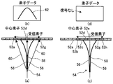
- FIG. 1 is a block diagram illustrating an ultrasonic diagnostic apparatus according to a first embodiment of the present invention. It is a conceptual diagram for demonstrating an example of the reception focus process in the ultrasonic diagnosing device shown in FIG. It is a block diagram which shows notionally an example of a structure of the element data process part of the ultrasonic diagnosing device shown in FIG. (A) And (c) is a conceptual diagram for demonstrating transmission / reception of the ultrasonic wave by an ideal ultrasonic beam, respectively, (b) and (d) are the elements obtained by transmission / reception of each ultrasonic wave It is a conceptual diagram which shows data.
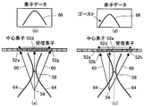
- FIG. (A) And (c) is a conceptual diagram for demonstrating transmission / reception of the ultrasonic wave by an actual ultrasonic beam, respectively
- (b) and (d) are element data obtained by transmission / reception of each ultrasonic wave
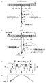
- FIG. (A) And (b) is a conceptual diagram for demonstrating the path
- (c) is several
- D) is a conceptual diagram for explaining each element data delay time shown in (c).
- (A), (b), and (c) are true signals
- (d), (e), and (f) are element data, their delay times, and element data overlapping states, respectively.
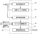
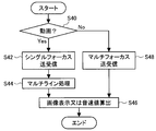
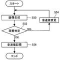
- FIG. It is a block diagram which shows notionally an example of a structure of the sound speed determination part of the ultrasonic diagnosing device shown in FIG. 4 is a flowchart for explaining an example of sound speed determination processing of the ultrasonic diagnostic apparatus shown in FIG. 1. It is a flowchart for demonstrating the sound speed determination method in the flowchart of FIG. It is a flowchart for demonstrating the still image shooting mode and moving image shooting mode of the 1st ultrasonic diagnostic apparatus of embodiment of this invention. It is a flowchart for demonstrating the sound speed determination method.
- FIG. 1 It is a block diagram which shows the ultrasonic diagnosing device of embodiment of the 2nd Embodiment of this invention.
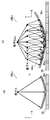
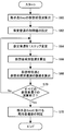
- (A) And (b) is a schematic diagram for demonstrating the calculation process of a local sound speed value. It is a flowchart for demonstrating an example of the calculation process of a local sound speed value. It is a block diagram which shows the ultrasonic diagnostic apparatus of Embodiment of the 3rd Embodiment of this invention.
- FIG. 1 is a block diagram showing an ultrasonic diagnostic apparatus according to the first embodiment of the present invention.
- the ultrasonic diagnostic apparatus 10 shown in FIG. 1 will be described in detail later.
- a moving image shooting mode in which a moving image is shot by continuously generating an ultrasonic beam in a time series, and an ultrasonic beam is temporarily generated.
- a still image shooting mode for performing still image shooting, and a shooting mode switching means for switching between the moving image shooting mode and the still image shooting mode.
- transmission / reception is performed with a single focus (single focus) with respect to the subject (inspection object), and a multi-layer which will be described in detail later based on the received element data (first element data).
- Line processing is performed, and an ultrasonic image (moving image) is created and displayed, or a sound velocity value is calculated.
- the image is transmitted and received with multi-focus (multiple focal points) within the subject, and an ultrasonic image (still image) is created and displayed.
- the sound speed value is calculated.
- the ultrasonic diagnostic apparatus 10 includes an ultrasonic probe 12, a transmission unit 14 and a reception unit 16 connected to the ultrasonic probe 12, an A / D conversion unit 18, and an element data storage unit 20.
- An element data processing unit 22 (first data processing means), a sound speed determination unit 23, an image generation unit 24, a display control unit 26, a display unit 28, a control unit 30, an operation unit 32, And a storage unit 34.
- the transmission unit 14, the reception unit 16, the A / D conversion unit 18, the element data storage unit 20, the element data processing unit 22, the sound speed determination unit 23, the image generation unit 24, the display control unit 26, and the display unit 28 are illustrated.
- the control unit 30, the operation unit 32, and the storage unit 34 constitute an apparatus main body of the ultrasonic diagnostic apparatus 10.
- the ultrasonic probe 12 (hereinafter referred to as the probe 12) has a probe array 36 used in a normal ultrasonic inspection apparatus.
- the probe array 36 has a plurality of elements arranged in a one-dimensional or two-dimensional array, that is, ultrasonic transducers. These ultrasonic transducers transmit an ultrasonic beam to a subject according to a drive signal supplied from the transmission unit 14 when imaging an ultrasonic image of the subject (inspection object), and also from the subject. Receives an ultrasonic echo and outputs a received signal.
- each of a predetermined number of ultrasonic transducers constituting a set of the plurality of ultrasonic transducers of the probe array 36 generates each component of one ultrasonic beam, and a predetermined number of sets.
- the ultrasonic transducer generates one ultrasonic beam to be transmitted to the subject.
- Each ultrasonic transducer is, for example, a piezoelectric ceramic represented by PZT (lead zirconate titanate), a polymer piezoelectric element represented by PVDF (polyvinylidene fluoride), or PMN-PT (magnesium niobate / lead titanate). It is composed of a vibrator in which electrodes are formed at both ends of a piezoelectric body made of a piezoelectric single crystal typified by a solid solution).
- PZT lead zirconate titanate
- PVDF polyvinylidene fluoride
- PMN-PT magnesium niobate / lead titanate
- the piezoelectric body When a pulsed or continuous wave voltage is applied to the electrodes of such a vibrator, the piezoelectric body expands and contracts in accordance with the applied voltage, and a pulsed or continuous wave ultrasonic wave is generated from each vibrator.
- the ultrasonic waves generated from the respective transducers are converged and synthesized (that is, transmitted and focused) according to the driving delay of the respective transducers to form an ultrasonic beam.
- the vibrator expands and contracts when an ultrasonic echo reflected in the subject is incident, and generates an electrical signal corresponding to the magnitude of the expansion and contraction. This electric signal is output to the receiving unit 16 as a received signal.
- the transmission unit 14 includes a plurality of pulsers and is a part that supplies a drive signal (applies a drive voltage) to each ultrasonic transducer (vibrator) of the probe 12.
- the transmission unit 14 includes, for example, a plurality of pulsers, and supplies a drive signal (applies a drive voltage) to each ultrasonic transducer (vibrator) of the probe 12.
- the drive signal is a predetermined number of ultrasonic transducers in a set of the probe array 36 according to the sound speed or the sound speed distribution set based on the transmission delay pattern selected according to the control signal from the control unit 30.
- the delay amount of each drive signal is adjusted so that an ultrasonic beam component transmitted from (hereinafter referred to as an ultrasonic element) forms one ultrasonic beam and is supplied to a plurality of ultrasonic elements forming a set.
- the delay amount of the drive signal so that the ultrasonic waves transmitted from the plurality of ultrasonic transducers form an intended ultrasonic beam that converges to a predetermined focal point (transmission focal point) set in the subject.
- Transmission focus for adjusting application timing of drive voltage
- a drive signal is supplied to the ultrasonic transducer.
- a large number of focal points can be set in the depth direction of the subject.
- the transmission delay pattern may be corrected according to an environmental sound speed value, a local sound speed value, and a sound speed correction value, which will be described later. In this way, the target ultrasonic beam is transmitted from the probe 12 (probe array 36) to the subject.
- the transmission unit 14 and the control unit 30 constitute a focus control unit.
- the receiving unit 16 receives ultrasonic echoes generated by the interaction between the ultrasonic beam and the subject from each of the ultrasonic elements of the probe array 36 from the subject. This is a part that receives and amplifies a reception signal, that is, an analog element signal for each ultrasonic element, and supplies the amplified analog element signal to the A / D converter 18.
- the method of transmitting and receiving ultrasonic waves is basically the same as that of a known ultrasonic diagnostic apparatus. Therefore, in one transmission / reception of ultrasonic waves (transmission of one ultrasonic beam and reception of ultrasonic echoes corresponding to this transmission), the number of ultrasonic transducers (number of transmission apertures) that generate ultrasonic waves, The number of ultrasonic transducers (the number of reception apertures) that receive ultrasonic waves (the reception unit 16 receives a reception signal) is not limited as long as it is plural. In one transmission / reception, the numerical aperture may be the same or different between transmission and reception.
- the transmission area overlaps at least with an ultrasonic beam adjacent in the azimuth direction (azimuth direction (arrangement direction of ultrasonic transducers))
- the number of times of transmission / reception of ultrasonic waves for forming one ultrasonic image There is no limitation on (number of sound rays) and the interval between ultrasonic transducers (central elements) that is the center of transmission and reception (that is, the density of scanning lines). Therefore, ultrasonic transmission / reception may be performed using all ultrasonic transducers corresponding to a region scanned with ultrasonic waves as a central element, and ultrasonic transducers at predetermined intervals, such as every two or every four, may be used as a central element. Ultrasonic waves may be transmitted and received.
- the receiving unit 16 may change the central element in response to the transmission of the ultrasonic beam by the transmitting unit 14.
- the A / D conversion unit 18 is connected to the reception unit 16 and performs analog / digital conversion on the analog reception signal supplied from the reception unit 16 to obtain element data (first element data) that is a digital reception signal. And The A / D converter 18 supplies the A / D converted element data to the element data storage unit 20.
- the element data storage unit 20 sequentially stores the element data supplied from the A / D conversion unit 18.
- the element data storage unit 20 associates information about the frame rate input from the control unit 30 (for example, parameters indicating the depth of the reflection position of the ultrasonic wave, the density of the scanning line, and the field width) with each element data.
- the element data storage unit 20 stores all element data corresponding to at least one ultrasonic image (one frame of ultrasonic image) and is displaying at least until the display of the ultrasonic image is finished. Also, the element data of the ultrasonic image before display is not deleted.
- the control unit 30 outputs the element data subjected to A / D conversion from the element data storage unit 20 to the element data processing unit 22.
- control unit 30 does not output the element data A / D converted from the element data storage unit 20 to the element data processing unit 22, and the sound speed determination unit 23 and the image generation unit 24. It is output to (phasing addition unit 38).
- the element data processing unit 22 is a feature of the present invention. In the moving image shooting mode, the element data processing unit 22 superimposes the element data and outputs processed element data (second element data) corresponding to each element data. It is a site to be generated. Specifically, the element data processing unit 22 is based on the control by the control unit 30, and among the element data stored in the element data storage unit 20, a central ultrasonic transducer (center element (center element)).
- the ultrasonic beam transmission areas overlap, the element data obtained by transmitting a predetermined number (multiple) of ultrasonic beams, the time at which each ultrasonic transducer receives an ultrasonic echo, and the ultrasonic transducer
- the processed element data corresponding to the element data is generated by superimposing them according to the positions of.
- the element data processing unit 22 outputs the generated processed element data to the sound speed determination unit 23 and the image generation unit 24.
- the sound speed determination unit 23 is a part that determines the sound speed (environmental sound speed) of the ultrasonic wave in the subject using the processed element data generated by the element data processing unit 22 in the moving image capturing mode. In the still image capturing mode, this is a part for determining the sound velocity (environmental sound velocity) of the ultrasonic wave in the subject using the element data subjected to A / D conversion in the element data storage unit 20.
- the element data processing unit 22 and processed element data, the sound speed determination unit 23, and the environmental sound speed will be described in detail later.
- the image generation unit 24 is configured to receive element data (first element data) supplied from the element data storage unit 20 or processed element data (second element data) supplied from the element data processing unit 22.
- Reception data (sound ray signal) is generated from the element data), and an ultrasonic image is generated from the reception data.
- a still image ultrasonic image is generated from the element data supplied from the element data storage unit 20, and a moving image ultrasonic image is generated from the processed element data supplied from the element data processing unit 22.
- the image generation unit 24 includes a phasing addition unit 38, a detection processing unit 40, a DSC 42, an image processing unit 44, and an image memory 46.
- the phasing addition unit 38 is connected to the element data storage unit 20, the element data processing unit 22, and the sound speed determination unit 23. In the moving image shooting mode, the phasing addition unit 38 outputs the processed element data generated by the element data processing unit 22 to the phasing. Addition is performed to perform reception focus processing, and reception data is generated. The distance between one reflection point in the subject is different for each ultrasonic transducer. Therefore, even when the ultrasonic echoes are reflected at the same reflection point, the time for the ultrasonic echoes to reach each ultrasonic transducer is different.
- the phasing addition unit 38 delays each reception data by an amount corresponding to the difference (delay time) in arrival time of ultrasonic echoes for each ultrasonic transducer according to the reception delay pattern selected by the control unit 30. By performing phasing addition of the reception data given the delay time, the reception focus processing is performed digitally to generate reception data. The phasing addition unit 38 supplies the generated reception data to the detection processing unit 40.
- a plurality of focal points are set in the depth direction within the subject, and the phasing adder 38 performs phasing addition of element data of one element to perform reception focus processing.
- the reception data is generated, and one line of reception data on the ultrasonic image of each focus is created.
- the phasing addition unit 38 functions as a second data processing unit.
- the phasing / adding unit 38 determines that the sound speed (environmental sound speed) of the ultrasonic wave in the subject is determined and supplied by the sound speed determining unit 23. In this case, this ambient sound speed is used to correct the delay time, the reception delay pattern, etc., and perform the reception focus process. If the ambient sound speed has not been determined, the phasing / adding unit 38 performs the reception focus process by a known method using the reception delay pattern as described above regardless of the moving image shooting mode or the still image shooting mode. I do.
- FIG. 2 shows an example of reception focus processing using ambient sound speed.
- FIG. 2 shows a case of a linear probe in which a plurality of ultrasonic transducers included in the probe 12 are arranged in a line in the left-right direction in FIG.
- the idea may be the same except that the probe shape is different.
- each ultrasonic transducer in the azimuth direction is L
- the distance from the ultrasonic transducer at the center in the azimuth direction to the nth ultrasonic transducer toward the end is nL.
- the reflection point of the ultrasonic wave is at a position (depth) d perpendicular to the arrangement direction from the central ultrasonic transducer, the nth ultrasonic transducer, the reflection point, and the distance (length) d n between, is calculated by the equation (1).
- the distance between the ultrasonic transducer and the reflection point is different for each ultrasonic transducer. Therefore, in the case of this example, as shown in the upper graph, the arrival time t n of the ultrasonic echo becomes longer as the ultrasonic transducer on the end side in the arrangement direction becomes longer.
- this delay time ⁇ t is a reception delay pattern.
- the phasing addition unit 38 performs phasing addition on the reception data corresponding to each ultrasonic transducer using the delay time represented by the time ⁇ t, and performs reception focus processing.
- the reception focus processing according to the environmental sound speed is not limited to this method, and various known methods can be used.
- the control unit 30 may select a reception delay pattern corresponding to the environmental sound speed and supply a control signal corresponding to the reception delay pattern to the phasing addition unit 38.
- the control unit 30 may correct the reception delay pattern according to the ambient sound velocity and supply a control signal corresponding to the corrected reception delay pattern to the phasing addition unit 38.
- the phasing addition part 38 may correct
- the detection processing unit 40 corrects attenuation according to the distance according to the depth of the reflection position of the ultrasonic wave on the reception data generated by the phasing addition unit 38, and then performs envelope detection processing to thereby detect the subject.
- B-mode image data display image data
- a DSC (digital scan converter) 42 converts the B-mode image data generated by the detection processing unit 40 into image data corresponding to a normal television signal scanning method (raster conversion).
- the image processing unit 44 performs various necessary image processing such as gradation processing on the B-mode image data input from the DSC 42 to obtain B-mode image data for display.
- the image processing unit 44 outputs the image-processed B-mode image data to the display control unit 26 for display and stores it in the image memory 46. It is not always necessary to store the image-processed B-mode image data in the image memory 46.
- the image memory 46 is a known storage unit (storage medium) that stores B-mode image data (display image data) processed by the image processing unit 44.
- the B-mode image data stored in the image memory 46 is read to the display control unit 26 for display on the display unit 28 as necessary.
- the display control unit 26 is a part that displays a moving image ultrasonic image or a still image ultrasonic image on the display unit 28 using the B-mode image data subjected to predetermined image processing by the image processing unit 44.
- the display unit 28 includes a display device such as an LCD, for example, and displays a moving image ultrasonic image or a still image ultrasonic image under the control of the display control unit 26.
- the control unit 30 is a part that controls each unit of the ultrasonic diagnostic apparatus 10 based on a command input from the operation unit 32 by the operator.
- the control unit 30 supplies various types of information input by the operator using the operation unit 32 to necessary parts. For example, information necessary for delay time calculation used in the element data processing unit 22 and the phasing addition unit 38 of the image generation unit 24 and information necessary for element data processing in the element data processing unit 22 are stored in the operation unit 32. When input is performed, these pieces of information are transmitted to the transmission unit 14, the reception unit 16, the element data storage unit 20, the element data processing unit 22, the image generation unit 24, the display control unit 26, and the like as necessary. Supply to each part.
- the operation unit 32 is for an operator to perform an input operation, and can be formed from a keyboard, a mouse, a trackball, a touch panel, and the like.
- the operation unit 32 also has an input function for the operator to input various types of information as necessary.
- the operation unit 32 includes information on generation of processed element data such as information on the probe 12 (ultrasonic transducer), transmission aperture and reception aperture in the probe 12 (transducer array), the number and method of element data to be superimposed, and the like.
- An input function for inputting the focal position of the ultrasonic beam is provided. These are input, for example, by selecting an imaging region (examination region), selecting an image quality, selecting a depth of an ultrasonic image to be captured, and the like.
- the operation unit 32 includes a freeze button for setting the ultrasonic diagnostic apparatus 10 to a moving image shooting mode or a still image shooting mode, and the operation unit 32 functions as a shooting mode switching unit.
- a setting signal for switching from the moving image shooting mode to the still image shooting mode is transmitted to the control unit 30, and the moving image shooting mode is switched to the still image shooting mode.
- the shooting mode switching unit is not limited to the freeze button, and a shooting mode switching unit that switches the above-described shooting modes may be provided.
- the storage unit 34 includes an operation program for the control unit 30 to control each unit of the ultrasound diagnostic apparatus 10, transmission delay patterns and reception delay patterns, information on generation of processed element data, and further from the operation unit 32. Information necessary for the controller 30 to operate and control the ultrasonic diagnostic apparatus, such as information on the input probe 12, transmission aperture and reception aperture, and focal position information, is stored.
- the storage unit 34 may be a known recording medium such as a hard disk, flexible disk, MO, MT, RAM, CD-ROM, DVD-ROM or the like.
- the element data processing unit 22, the sound speed determination unit 23, the phasing addition unit 38, the detection processing unit 40, the DSC 42, the image processing unit 44, the display control unit 26, etc. Is composed of an operation program for causing the computer to perform various processes.
- these parts may be constituted by digital circuits.
- the element data processing unit 22 is different from the element data (unprocessed element data) stored in the element data storage unit 20 in that the central ultrasonic transducer (center element) is different, and the ultrasonic beam
- the element data obtained by transmitting a predetermined number (multiple) of ultrasonic beams with overlapping transmission areas are superimposed according to the time received by each ultrasonic transducer and the position of the ultrasonic transducer, and processed element data is obtained. It is a site to be generated.
- the ultrasonic transducer is also simply referred to as “element”.
- FIG. 3 conceptually shows the configuration of the element data processing unit 22 in a block diagram.
- the element data processing unit 22 includes a delay time calculation unit 48 and an overlay processing unit 49.
- the delay time calculation unit 48 receives the probe 12 (ultrasonic transducer (element)) input from the operation unit 32 or input from the operation unit 32 and stored in the storage unit 34, the focal position of the ultrasonic beam, Information about the transmission aperture and the reception aperture of the probe 12 is acquired in advance.
- the delay time calculation unit 48 also includes a geometrical arrangement of a transmission aperture element that oscillates an ultrasonic wave to transmit (generate) an ultrasonic beam and a reception aperture element that receives an ultrasonic echo from the subject. Based on the correct position, the ultrasonic echo received by the element of the reception aperture, that is, the delay time of the element data is calculated.
- the superposition processing unit 49 relates to element data processing such as the number of element data to be superposed and the superposition processing method input from the operation unit 32 or input from the operation unit 32 and stored in the storage unit 34. Based on the information, from the element data stored in the element data storage unit 20, element data to be superimposed (element data obtained by an ultrasonic beam having different central elements and overlapping transmission areas (two or more target data) Read two or more element data)) generated for each region. Furthermore, the superimposition processing unit 49 receives two or more element data on the reception time, that is, in accordance with the time based on the delay time corresponding to each element data calculated by the delay time calculation unit 48. And the absolute position of the received element of the probe is matched and superposed to generate processed element data.
- an ultrasonic beam is transmitted to a subject from a transmission aperture, that is, an element that transmits ultrasonic waves to transmit an ultrasonic beam (hereinafter simply referred to as a transmission element)
- a transmission element an element that transmits ultrasonic waves to transmit an ultrasonic beam
- the receiving element receives the ultrasonic echo
- the transmitting unit 14 transmits an ultrasonic beam using the three elements 52c to 52e as transmitting elements and receives an ultrasonic echo using the seven elements 52a to 52g as receiving elements.
- the element is moved in the azimuth direction by one element (hereinafter also referred to as a shift), and an ultrasonic beam is transmitted using the three elements 52d to 52f as transmitting elements.
- the ultrasonic echoes are received by the receiving unit 16 using the two elements 52b to 52h as receiving elements, and element data is acquired respectively. That is, in the example shown in FIG. 4A, the central element (the central element) is the element 52d, and in the example shown in FIG. 4B, the central element is the element 52e.
- the ultrasonic beam 56 to be transmitted to the inspection target region including the reflection point 54 is converged at the focal point 58 and narrowed to the element interval or less.
- the ultrasonic beam 56 is transmitted from the elements 52c to 52e serving as transmitting elements, with the element 52d located directly above the reflecting point 54 (on the straight line connecting the reflecting point and the focal point) as the central element.
- the focal point 58 of the ultrasonic beam 56 is on a straight line connecting the element 52d as the central element and the reflection point 54.
- the ultrasonic beam 56 is transmitted to the reflection point 54, an ultrasonic echo reflected from the reflection point 54 is generated.
- the ultrasonic echoes from the reflection point 54 are received by the elements 52a to 52g as the receiving elements through the receiving path 60 spreading at a predetermined angle, and the element data 62 as shown in FIG. 4B is received by the elements 52a to 52g. Is obtained.
- the vertical axis represents time
- the horizontal axis represents the position in the azimuth direction (element position) coinciding with FIG. 4A (the same applies to FIG. 4D).
- the ultrasonic beam 56 is transmitted from the elements 52d to 52f which are transmitting elements, and ultrasonic echoes are received by the elements 52b to 52h which are receiving elements.
- the ultrasonic beam 56 is ideal, the reflection point 54 does not exist on the transmission direction of the ultrasonic beam 56, that is, on the straight line connecting the center element 52 e and the focal point 58. Therefore, the ultrasonic beam 56 is not transmitted to the reflection point 54. Therefore, an ultrasonic echo reflected from the reflection point 54 is not generated, and the elements 52b to 52h that are reception elements do not receive the ultrasonic echo, and as shown in FIG. A reflection signal cannot be obtained (the signal intensity of element data is “0”).
- the width is wider than the element spacing.
- the ultrasonic beam 64 is transmitted using the element 52d immediately above the reflection point 54 as the central element and the elements 52c to 52e as the transmitting elements.
- the focal point 58 is on a straight line connecting the element 54d and the reflection point 54. Therefore, the ultrasonic beam 64 is reflected at the reflection point 54, and an ultrasonic echo is generated.
- the ultrasonic echo from the reflection point 54 is received by the elements 52a to 52g as the receiving elements through the receiving path 60 spreading to a predetermined angle.
- True element data 66 as shown in FIG. 5B is obtained.
- the central element is shifted by one element, and the ultrasonic beam 56 is transmitted with the adjacent element 52e as the central element and the elements 52d to 52f as the transmitting elements. Transmitting and receiving ultrasonic echoes using the elements 52b to 52h as receiving elements. Even in this case, since the ultrasonic beam 64 is wide, even if the reflection point 54 does not exist on the transmission direction of the ultrasonic wave, that is, the straight line connecting the element 52e as the central element and the focal point 58, The sound beam 64 is transmitted (arrives) to the reflection point 54.
- an ultrasonic echo that does not originally exist that is, a so-called ghost reflection echo is generated from the reflection point 54 in the transmission direction of the ultrasonic beam.
- the ghost reflection echo from the reflection point 54 is received by the elements 52b to 52h, which are reception elements, through the reception path 60 that spreads to a predetermined angle.
- ghost element data 68 as shown in FIG. 5D is obtained by the elements 52b to 52h.
- Such ghost element data 68 causes a decrease in the accuracy of the ultrasonic image generated from the element data.
- the element data processing unit 22 calculates a delay time corresponding to the element data by the delay time calculation unit 48, and the overlay processing unit 49 determines that the two or more element data correspond to the delay time and the absolute position of the element. By superimposing them, the true element data is emphasized, and the processed element data, which is highly accurate element data in which the ghost element data is attenuated, is generated.
- the delay time calculation unit 48 calculates the delay time of the element data received by each element of the reception element (reception aperture). That is, the propagation distance of the ultrasonic beam 64 shown in FIG. 5C is such that the ultrasonic beam 64 is transmitted from the central element 52e through the focal point 58 to the reflection point 54, and the reflection echo of the ghost is the reflection point 54. To the receiving path from the receiving elements 52b to 52h.
- the propagation distance of the ultrasonic beam 64 shown in FIG. 5C is the propagation distance of the ultrasonic beam 64 shown in FIG. 5A, that is, the ultrasonic beam 64 is reflected from the central element 52d via the focal point 58.
- the transmission path to the point 54 and the true ultrasonic echo are longer than the sum of the reception path from the reflection point 54 to the receiving elements 52a to 52g. For this reason, the ghost element data 68 as shown in FIG. 5D is delayed with respect to the true element data 66 as shown in FIG. 5B.
- the delay time calculation unit 48 of the element data processing unit 22 the time difference between the ghost element data and the true element data, that is, the delay time is the sound speed, the transmission element, the focal point of the ultrasonic beam, the reflection point of the subject, and the reception. Calculated from the element geometry. Therefore, calculation of the delay time requires information such as the shape of the probe 12 (element spacing, linear, convex, etc.), sound speed, focal position, transmission aperture, reception aperture, and the like.
- the delay time calculation unit 48 obtains the information input by the operation unit 32 or stored in the storage unit 34, and calculates the delay time.
- the sound speed may be a preset fixed value (for example, 1540 m / sec), may be a sound speed (environmental sound speed) determined by a sound speed determining means described later, or the operator may You may enable it to input.
- the delay time is calculated from, for example, the geometrical arrangement of the transmission element, the focal point of the ultrasonic beam, the reflection point of the subject, and the reception element, and the transmission path of the ultrasonic beam from the transmission element to the reflection point through the focal point. And the total length (propagation distance) of the reception path of the true reflected ultrasonic echo or ghost reflected signal from the reflection point to the receiving element, and the difference between the propagation times calculated by the sound speed.
- the lengths of the transmission path and the reception path of the ultrasonic beam in the case of a true ultrasonic echo and a ghost reflection echo are obtained.
- the x direction is the azimuth direction and the y direction is the depth direction.
- 6A performs transmission / reception of ultrasonic waves similar to FIG. 5A
- FIG. 6B performs transmission / reception of ultrasonic waves similar to FIG. 5C.
- the center element 52d, the focal point 58, and the reflection point 54 have the same position in the azimuth direction. ing. That is, the focal point 58 and the reflection point 54 are located directly below the central element 52d. Therefore, if the position of the element 52d as the central element is the coordinates (x0, 0) on the xy two-dimensional coordinates, the x coordinates of the focal point 58 and the reflection point 54 are also “x0”.
- the position of the focal point 58 in this transmission is set to coordinates (x0, df)
- the position of the reflection point 54 is set to coordinates (x0, z)
- the element interval is set to Le.
- the transmitting element and the receiving element are shifted by one element in the x direction (azimuth direction) (shifted to the right in the figure), and transmission / reception is performed using the central element as the element 52e. .
- FIG. 5C in this case, what is reflected at the reflection point 54 is a ghost reflection echo.
- the reflection point 54 is located at the same position in the azimuth direction of the element 52d. Therefore, as shown in FIG. 6B, in this transmission / reception, the position in the x direction between the element 52e as the central element and the reflection point 54 is shifted in the x direction by one element, that is, by Le.
- the coordinate of the element 52d whose position in the x direction coincides with the reflection point 54 is (x0, 0)
- the coordinate of the element 52e as the central element is (x0 + Le, 0)
- the coordinate of the focal point 58 in this transmission is (x0 + Le). , Df).
- a value obtained by dividing the ultrasonic propagation distance Lua which is the sum of the distance Lta of the transmission path 61 and the distance Lra of the reception path 60, obtained by the geometric arrangement shown in FIG. This is the echo propagation time.
- the value obtained by dividing the ultrasonic propagation distance Lub which is the sum of the distance Ltb of the transmission path 61 and the distance Lrb of the reception path 60 obtained by the geometric arrangement shown in FIG. Propagation time.
- the delay time is the propagation time of the true ultrasonic echo when the x-coordinate between the reflection point 54 and the central element coincides, and when the x-coordinate between the reflection point 54 and the central element is shifted by one element interval.
- the transmission path 61 is a model passing through the focal point 58.
- the present invention is not limited to this, and for example, via the focal point 58. Instead, the path directly reaching the reflection point 54 may be used.
- FIG. 6A and FIG. 6B is a case of a linear probe, not only this but the other geometrical calculation can be performed from the shape of a probe. .
- a geometric model can be set from the probe radius and the element spacing angle, and the calculation can be performed in the same manner.
- the delay time is not limited to the method of calculating the delay time using the geometric model, and the delay time is obtained for each measurement condition from the measurement result obtained by measuring the high-intensity reflection point according to the measurement condition of the apparatus in advance. By storing in the apparatus, the delay time of the same measurement condition may be read out.
- FIG. 6C shows true element data 66 and ghost element data 68.
- the center of the azimuth direction is true element data 66, that is, element data obtained by transmission / reception in which the center element and the reflection point 54 have the same position in the x direction (in the illustrated example, Element data with the element 52d as the central element).
- ghost element data on both sides of the center that is, element data obtained by transmission / reception in which the center element and the reflection point 54 do not coincide with each other in the x direction (in the illustrated example, element data 52c or element 52e, etc. Element data as a central element).
- FIG. 6C the center of the azimuth direction is true element data 66, that is, element data obtained by transmission / reception in which the center element and the reflection point 54 have the same position in the x direction (in the illustrated example, Element data with the element 52d as the central element).
- ghost element data on both sides of the center that is, element data obtained by transmission / reception in which the center element and the reflection point 54
- FIG. 6D shows an example of the delay time of the ghost element data 68 with respect to the true element data 66 obtained from the above-described geometric calculation. It is shown that the element data 68 of the ghost signal is symmetrically delayed in the x direction, that is, the azimuth direction, with the true element data 66 as the center. In this way, the delay time calculated by the delay time calculation unit 48 of the element data processing unit 22 can also be used for delay correction in the phasing addition unit 38.
- the element data obtained by transmitting an ultrasonic beam having a certain element of interest as the central element differs from the central element, and at least of the ultrasonic beam.
- the processed element data (second element data) of the element of interest is overlapped. ) (Reconstruct the element data of the element of interest).
- a reflection point 54 indicates the position (element data output position) of a certain sampling point located directly below the target element (same position in the azimuth direction / on the straight line connecting the target element and the focal point).
- the transmission / reception path to the sampling point in the transmission / reception of the element of interest is regarded as the transmission / reception path of the true element data, and the transmission / reception path to the same sampling point in the transmission / reception of ultrasonic waves with different central elements (transmission / reception from peripheral elements)
- a delay time is calculated from the difference between the two transmission paths, and the element data time is combined using this delay time to perform superposition.
- the processing by the delay time is matched and the signal is emphasized.
- the delay time is used. The signal is canceled without the processing being matched.
- the overlay processing of the element data is performed using the delay time thus calculated by the delay time calculating section 48.
- the overlay processing in the overlay processing unit 49 requires information on the number of superimposing element data and the overlay processing method at the time of overlaying, but these may be input in advance by the operation unit 32. It may be stored in the storage unit 34.
- FIGS. 7A to 7H show an example of the overlay process performed by the overlay processor 49.
- FIG. The example shown in FIG. 7 is a case where the number of element data is five and the number of overlapping element data is three.
- FIG. 7A shows five element data obtained by transmitting and receiving five ultrasonic waves side by side.
- FIG. 7A shows a state where an ultrasonic beam is transmitted and an ultrasonic echo is received for each element data.
- the horizontal axis of each element data represents a receiving element, and the respective element data are displayed centering on the central element in transmission / reception of the ultrasonic beam.
- the vertical axis represents the reception time.
- the center elements such as the elements 52b to 52f are shifted one element at a time, and ultrasonic waves are transmitted and received five times.
- FIG. 7 shows a state in which one reflection point exists only directly below the central element in the central element data. That is, among the five element data, in the middle element data, a true ultrasonic echo from the reflection point is received in transmission / reception of ultrasonic waves. That is, the middle element data is true element data.
- the reflection echo element data that is, the ghost element data
- the propagation time of the ultrasonic wave to the reflection point becomes longer, so that the reception time becomes slower than the true element data.
- the position of the receiving element where the ultrasonic echo from the reflection point is first received is shifted in the azimuth direction, in this case.
- the central element since the central element is shifted by one element for each element data, the absolute position of the element in the azimuth direction is shifted by one element in each element data. That is, in the middle element data, the receiving element from which the reflected signal from the reflection point is first received is the central element. However, in the adjacent element data, one element is shifted from the middle element data. The element data is shifted one element to the left, and the element data on the left is shifted one element to the right. Further, the element data at both ends are shifted by two elements from the middle element data, the leftmost element data is shifted two elements to the left, and the leftmost element data is shifted two elements to the right. As described above, the ghost signal is not only delayed in reception time with respect to the true signal, but also deviated from the direction of the receiving element.
- FIG. 7B shows an example of the delay time of the reception time for the middle element data among the five element data shown in FIG.
- the overlay processing unit 49 uses the delay time shown in FIG. 7B to set the center element data as the element data of the element of interest, and the number of element data to be superimposed around the element data of the element of interest.
- the delay time is corrected by three element data, and each element data is azimuthed by one element on both sides in the illustrated example in accordance with the difference in element position from the target element (difference in the position of the central element). That is, the unprocessed element data corresponding to the three element data is overlapped by shifting in the direction, that is, the phase is matched to obtain one overlapped element data of the element data of the element of interest.
- the element data obtained by transmission / reception of the ultrasonic wave with the target element as the central element (hereinafter also referred to as element data of the target element) is the ultrasonic wave with the element adjacent to the target element as the central element.
- the element data obtained by the transmission / reception (hereinafter also referred to as element data of the adjacent element) is superimposed to generate processed element data of the element data of the element of interest.
- FIG. 7C shows element data that has been subjected to the overlay processing of the element data of the element of interest obtained in this way.
- the element data of the target element shown in FIG. 7A is true element data in which a reflection point exists immediately below the central element (that is, the target element).
- element data obtained by transmission / reception using an element adjacent to the element of interest as a central element is also data of reflected ultrasonic echoes incident on the reflection point. Therefore, when phase alignment is performed by performing delay time correction and azimuth direction shift on the element data of the adjacent element on both sides of the element of interest, as shown in FIG. Since the phase matches the element data of the element, they overlap at a high luminance position. Therefore, when these element data are added, for example, the element data value shows a large value (high luminance value), and for example, even if an average value is obtained by averaging, an emphasized value (high luminance value) is shown.
- FIG. 7D shows the same element data as FIG. 7A, but shows an example in which the element data on the left side of the middle element data is the element data of the element of interest. That is, this example shows an example of the case where the central element is the element of interest in the transmission / reception of ultrasonic waves with the element having no reflection point directly below as the central element. Therefore, element data having this element as a central element is ghost element data.
- FIG. 7 (e) is the same as FIG. 7 (b), and shows an example of the delay time of the reception time for the element data of the target element of the five element data shown in FIG. 7 (a). That is, since FIG. 7A and FIG.
- the delay time of the reception time with respect to the element data of the target element of the five element data shown in FIG. 7D is the same.
- the delay time shown in FIG. 7E (that is, the same as FIG. 7B) is used for the number of overlay element data, centering on the element data of the element of interest.
- the delay time is corrected by three element data, and each element data is shifted in the azimuth direction by one element on both sides in the illustrated example according to the difference in element position from the element of interest (difference in the position of the central element).
- the unprocessed element data for the three elements are overlapped to obtain one overlapped element data of the element data of the element of interest.
- FIG. 7F shows element data that has been subjected to the overlay processing of the element data of the element of interest obtained in this way.
- the element data of the element of interest shown in FIG. 7D is ghost element data. Therefore, even if the unprocessed element data of the adjacent element data on both sides of the element data of the element of interest is subjected to the delay time correction and the azimuth shift to perform phase alignment, as shown in FIG.
- the element data of the element and the element data of the element of interest do not overlap each other because the phases do not match each other. For this reason, even if these three element data are added, for example, because the signals are not in phase because the phases are not matched, the signals are reversed, so the added value does not increase.
- the average value is obtained by averaging, a small value is shown.
- FIG. 7H shows a result obtained by performing, for example, addition processing or averaging processing as superimposing processing on these as shown in g).
- FIG. 7 (h) in the case of element data in which the central element having the reflection point immediately below it shown in FIG. 7 (a) is the element of interest, the element data of the true signal has a high luminance value. Is obtained as superposed processed element data.
- an element is a target element
- the element data (element data of the target element) obtained by transmitting an ultrasonic beam using the target element as a central element is different from the central element
- element data equal to the case where the focal point is formed at a number of points on the sound ray to be transmitted without the influence of ghost
- element data reception data (ultrasound image data)
- the sound velocity in the subject can be accurately determined.
- the influence of the ghost is eliminated, that is, all points on the sound ray. Therefore, an ultrasonic image can be generated with the same element data as that focused on, so that a high-quality ultrasonic image with high brightness and excellent sharpness can be generated.
- the generation of processed element data is also referred to as multiline processing.
- processed element data generated by multi-line processing eliminates the effects of ghosts, and is equivalent to element data when focusing at many points on the sound ray to be transmitted.
- This is element data obtained by transmitting ultrasonic waves. Therefore, according to the present invention in which the sound ray is determined using the processed element data, the transmission of one sound ray and one focal point ultrasonic wave is equal to or more than the case of transmitting one sound ray multifocal ultrasonic wave.
- the sound speed can be determined with high accuracy. Further, since the sound speed can be determined with high accuracy by transmitting one sound ray and one focal point ultrasonic wave, it is possible to prevent the frame rate from being lowered due to the sound speed determination (sound speed update). Therefore, it is effective in the moving image shooting mode.
- the processed element data of the element data of the element of interest is generated, the present invention is not limited to this.
- the processed element data may be generated by superimposing element data obtained by transmitting a plurality of ultrasonic beams having different transmission directions (angles) with the same central element.
- which element data obtained by transmission of the ultrasonic beam to generate the processed element data depends on the diagnosis site or the probe.
- the central element is different, using both the element data obtained by transmission of parallel ultrasonic beams and the element data obtained by transmission of ultrasonic beams having different transmission directions with the same central element, Processed element data may be generated.
- the central element is a central element in the azimuth direction when the numerical aperture for transmission (the number of elements for transmitting ultrasonic waves) is an odd number, and the azimuth direction when the numerical aperture is an even number.
- the central element is assumed to be in the middle of any one of the central elements in the direction or the central element in the azimuth direction. That is, when the numerical aperture is an even number, the calculation is performed on the assumption that the focal point is on the middle line of the aperture.
- the overlay processing method in the overlay processing unit 49 is not limited to addition, but may be an average value or a median value, or may be added after multiplying coefficients. Note that taking an average value or a median value is considered to correspond to applying an averaging filter or a median filter at the element data level, but instead of the averaging filter and the median filter, it is performed by normal image processing. An inverse filter or the like may also be applied. Alternatively, each element data to be overlapped is compared, and if they are similar, the maximum value is taken, the average value is taken if they are not similar, and the intermediate value is taken if there is a distribution deviation. The overlay process may be changed based on the feature amount of each element data to be superimposed.
- the number of element data to be superimposed on the element data of the element of interest is not limited to two in the illustrated example, and may be one or three or more. That is, the number of element data to be superimposed on the element data of the element of interest may be appropriately set according to the required processing speed (frame rate or the like) or image quality.
- the number of element data to be superimposed on the element data of the element of interest matches the extent of the beam width of the ultrasonic beam. Therefore, when the beam width changes depending on the depth, the number of element data to be superimposed may be changed depending on the depth.
- the number of element data to be superimposed may be changed according to the transmission numerical aperture.
- the number of overlapping element data may be changed based on the feature value such as the luminance value of the image, or the optimum number of overlapping element data is selected from images created by changing the number of overlapping element data in multiple patterns. May be.
- the element data processing unit 22 outputs the generated processed element data to the image generation unit 24 (phasing addition unit 38) and the sound speed determination unit 23.
- the phasing addition unit 38 performs phasing addition on the processed element data, performs reception focus processing, and generates reception data.
- 40 generates B-mode image data by performing attenuation correction and envelope detection processing on the received data.
- the DSC 48 raster-converts the B-mode image data into image data corresponding to a normal television signal scanning method, and the image processing unit 44 performs predetermined processing such as gradation processing.
- the image processing unit 44 stores the generated B-mode image data in the image memory 46 and / or sends it to the display control unit 26 so that the display unit 28 displays the B-mode image of the subject.
- the sound speed determination unit 23 determines the sound speed of the ultrasonic wave in the subject (calculates the sound speed) using the supplied processed element data.
- FIG. 8 conceptually shows the configuration of the sound speed determination unit 23 in a block diagram. As shown in FIG. 8, the sound speed determination unit 23 includes a region-of-interest setting unit 70, a transmission focus control unit 72, a set sound speed designating unit 74, a focus index calculation unit 76, and an environmental sound speed determination unit 78.
- the attention area setting unit 70 sets the attention area on the B-mode image (on the ultrasonic image) in accordance with an instruction from the control unit 30.
- the sound speed determination unit 23 determines the sound speed of the subject for each region of interest.
- the region-of-interest setting unit 70 divides the entire screen of the B-mode image into a lattice shape, and sets each of the regions as the region of interest.
- the number of divisions may be set in advance by default, or may be arbitrarily set by the operator in the azimuth direction and / or depth direction. When the number of divisions is set by default, different settings may be provided for each image size and each observation region. Furthermore, a plurality of division numbers may be set in advance so that the operator can select them.
- the region of interest is not limited to each region obtained by dividing the B-mode image in a grid pattern.
- all the pixels (positions (regions) corresponding to all the pixels) that generate reception data (B-mode image data) may be used as the region of interest.
- the screen may be divided into a grid corresponding to all the pixels that generate the reception data.
- the entire screen may be a single region of interest.
- a part of the screen that is set in advance or selected from a plurality of options may be divided into a lattice shape, and each of them may be set as a region of interest.
- the region of interest may be set not for the entire screen but for the ROI set by the operator. Even when a region of interest is set in a part of the screen or in the ROI, the division may be performed in the same manner as the entire screen. Further, the operator may be able to select the setting of the attention area in the entire screen and the setting of the attention area in the ROI.
- the shape to be divided is not limited to the lattice shape, and for example, if it is a fan-shaped B-mode image such as an ultrasonic image obtained by a convex probe, the shape to be divided may be a fan shape. Also in this case, all of the above aspects can be used.
- the region of interest is when the image fluctuates greatly (for example, when the fluctuation value of the image feature amount exceeds a threshold value), or when the observation condition is changed, such as changing the observation magnification or changing the observation depth.
- the area of interest may be changed or updated, and the operator may be instructed to change or update the area of interest.
- the region-of-interest setting unit 70 further sets a focal point (focal position) for performing ultrasonic transmission (transmission focus) corresponding to the determination of the sound speed for the set region of interest.
- the focal point may be set in advance as a default according to the observation site, the number of sound rays, the numerical aperture for transmission / reception, the type of the probe 12, and the like, or may be selected or input by the operator, or set as a default. It is also possible to select an instruction city by the operator.
- the present invention in which the sound speed is determined using the processed element data obtained by superimposing the element data can perform transmission by virtual multi-focus. For this reason, in the moving image shooting mode, basically, one focal point is set for one sound ray. As a result, the sound speed can be determined even during moving image shooting.
- the element data is data that is focused at any depth by multi-line processing, so the ROI setting interval can be set freely. For example, it is possible to obtain a sound speed value with improved spatial resolution by setting the ROI interval more finely than in the case of a still image.
- the transmission focus control unit 72 instructs the control unit 30 to perform a transmission focus so that the transmission unit 14 performs transmission focus according to the target region and focus set by the target region setting unit 70.
- the set sound speed designating unit 74 designates a set sound speed for executing the reception focus on the received data in determining the environmental sound speed based on the control of the control unit 30.
- the focus index calculation unit 76 uses the element data stored in the element data storage unit 20 or the processed element data generated by the element data processing unit 22 to convert the received data into a plurality of set sound speeds designated by the set sound speed designation unit 74. On the other hand, reception focus is performed and a focus index of reception data is calculated.
- the environmental sound speed determination unit 78 determines the environmental sound speed of the region of interest based on a focus index for each of a plurality of set sound speeds.
- the attention area setting section 70 sets the attention area and the focus in accordance with an instruction from the control section 30 (step S10). ).
- the timing for determining the environmental sound speed is not particularly limited, and may be performed in the same manner as a known ultrasonic diagnostic apparatus. For example, it may be performed only once in response to an instruction to start measurement, and the environmental sound speed may be determined when the image greatly fluctuates (when the variation value of the image feature amount exceeds a threshold value).
- the environmental sound speed may be determined every predetermined number of frames or every elapse of a predetermined time, or the environmental sound speed may be determined according to an input instruction from the operator, and two or more of these sound speed determination timings may be determined. May be selected as appropriate.
- the ambient sound speed is also determined in the moving image shooting mode. be able to.
- the transmission focus control unit 72 In response to the setting of the region of interest, the transmission focus control unit 72 gives a transmission focus instruction to the control unit 30 so that the transmission unit 14 performs transmission focus on the set region of interest and focus.
- the transmitter 14 drives the probe 12 (corresponding ultrasonic transducer (element) of the probe array 36) to transmit an ultrasonic beam to the subject, and the ultrasonic wave reflected by the subject.
- the echo is received by the element, and an analog reception signal is output from the ultrasonic transducer (element) to the receiving unit 16 (step S12).
- the reception unit 16 performs predetermined processing such as amplification on the analog reception signal and supplies the analog reception signal to the A / D conversion unit 18.
- the A / D conversion unit 18 performs A / D conversion on the analog reception signal supplied from the reception unit 16 to obtain element data which is a digital reception signal.
- the element data is stored in the element data storage unit 20 (step S14).
- the element data processing unit 22 When the element data is stored in the element data storage unit, the element data processing unit 22 performs the above-described multiline processing to generate processed element data. That is, as shown in FIG. 7 described above, the element data processing unit 22 sets, for example, the delay time of the element data of the adjacent elements with respect to the element data of the target element for the target element and the adjacent elements. Calculate, perform delay time correction of the element data of the adjacent element and shift in the azimuth direction, and overlay the element data of the adjacent element on both sides with the element data of the target element to generate processed element data of the target element (Step S16). The element data processing unit 22 supplies the generated processed element data to the sound speed determination unit 23 (focus index calculation unit 76). The element data processing unit 22 also supplies the generated processed element data to the image generation unit 24, and the image generation unit 24 uses this processed element data to generate an ultrasonic image (B-mode image data). Is generated as described above.
- the sound speed determination unit 23 determines the sound speed of the ultrasonic wave in the subject using the supplied processed element data (step S18).
- FIG. 10 shows a flowchart of an example of a sound speed determination method in the sound speed determination unit 23.
- the sound speed determination method in the sound speed determination unit 23 is not limited to this method, and various sound speed determination methods (sound speed calculation methods) performed in the ultrasonic diagnostic apparatus can be used. .
- the sound speed determination unit 23 stores the processed element data in a predetermined part as necessary, and first sets the start sound speed Vst and the end sound speed Vend of the set sound speed V ( In step S20), the starting sound speed Vst is set as the set sound speed V (step S22).
- the set sound speed including the start sound speed Vst and the end sound speed Vend may be set in advance as a default, or the operator arbitrarily inputs only the start sound speed Vst and the end sound speed Vend, and a step size (predetermined step). Only the sound speed amount ⁇ V) may be set by default, or may be arbitrarily input by the operator.
- the set sound speed and the set sound speed increment are set by default, a plurality of types of set sound speeds are set according to the observation site or sex, so that the operator can select as appropriate. Good.
- 1410 m / sec is set as the start sound speed Vst
- 1570 m / sec is set as the end sound speed Vend
- the set sound speed is set at an interval of 40 m / sec as a predetermined step size.
- the focus index calculation unit 76 performs reception focus on the processed element data for each of a plurality of set sound speeds specified by the set sound speed specification unit 74 corresponding to each region of interest, and calculates the focus index of the received data. (Step S24). Specifically, the focus index calculation unit 76 integrates the received data (ultrasound image data / ultrasound image), square integral value, peak value, sharpness, contrast, luminance value, Calculate half-width, frequency spectrum integration, frequency spectrum integrated value or square integrated value normalized by maximum value or DC component, autocorrelation value, etc. as focus index
- the sound speed determining unit 23 determines whether the set sound speed V has reached the end sound speed Vend in the set sound speed designating unit 74 (step S26). If the set sound speed V is less than the end sound speed Vend (No), a predetermined sound speed is determined. The step sound speed amount ⁇ V, that is, 40 m / sec in this example, is added to the set sound speed V (step S28), and the focus index of the region of interest is calculated. When this routine is repeated and it is determined that the set sound speed V has reached the end sound speed Vend (Yes), the environmental sound speed determination unit 78 focuses on the set sound speed of the highest focus index based on the focus index for each of the plurality of set sound speeds.
- the environmental sound speed of the region of interest is determined by setting the environmental sound speed of the region (step S30). For example, using the brightness of the ultrasonic image as a focus index, the sound speed at which the highest brightness ultrasonic image is obtained in the region of interest is set as the environmental sound speed of the region of interest. That is, the environmental sound velocity in this example is the ultrasonic probe 12 and the region of interest when it is assumed that the sound velocity from the probe 12 (the probe array 36 (ultrasonic transducer)) to a certain region of interest is constant. The average speed of sound in the area between. As described above, the sound speed determination unit 23 determines the ambient sound speed in all the set regions of interest.
- the ambient sound speed determined by the sound speed determination unit 23 is stored in the element data storage unit 20 in association with the position information in the ultrasonic image.
- the determined ambient sound speed is supplied to the phasing adder 38 and used for reception focus processing. Thereby, an ultrasonic image based on the environmental sound speed is displayed on the display unit 28.
- the environmental sound speed is determined in the same manner as the processed element data generated by the multi-line process, even when the A / D converted element data is used instead of the processed element data generated by the multi-line process.
- the ambient sound speed can be determined as follows. For this reason, detailed description of the determination method of the environmental sound speed using the element data is omitted.
- the ambient sound speed determined by the sound speed determination unit 23 is stored in the element data storage unit 20 in association with the position information in the ultrasonic image.
- the ambient sound velocity value determined using the element data is supplied to the phasing adder 38 and used for the reception focus process.
- An ultrasonic image based on the environmental sound speed is displayed on the display unit 28.
- the ultrasonic diagnostic apparatus 10 basically has the above configuration.
- the ultrasonic diagnostic apparatus 10 has a moving image shooting mode and a still image shooting mode.
- moving image shooting is performed by continuously generating ultrasonic beams in a time series.
- transmission / reception is performed with single focus
- element data is obtained
- the above-described multiline processing is performed based on the element data to obtain processed element data.
- the processed element data is subjected to a phasing addition process to obtain B-mode image data, and an ultrasonic image is displayed on the display unit 28 as a moving image.
- the element data is repeatedly obtained while shifting the central element in the element arrangement direction, that is, scanning in the arrangement direction.
- single focus is not necessarily required.
- the focus may be plural if the frame rate is 5 fr / sec or more.
- the still image shooting mode as described above, transmission / reception is performed with multi-focus as in the prior art to obtain element data.
- a phasing addition process is performed on the element data, one line of data on the ultrasonic image is generated based on one element data, and then B-mode image data is obtained, and the ultrasonic image is displayed as a still image. 28.
- the element data is obtained repeatedly by shifting the central element in the element arrangement direction, that is, scanning in the arrangement direction.
- the scanning direction and scanning method for obtaining an ultrasonic image are not particularly limited, and known methods and methods can be appropriately used.
- the data obtained in the video shooting mode may be used for the focus that corresponds to the focus of the video among the many focal points when creating a still image. it can. Thereby, the time required for creating a still image can be shortened.
- the still image shooting mode it is not necessary to consider the frame rate as compared with the moving image shooting mode, and a plurality of focal positions are set for one sound ray (one line of the ultrasonic image), compared to the moving image shooting mode.
- the image quality of the ultrasonic image is assumed to be good.
- the position of the focal point may be the same for all sound rays, or sound rays having different focal points may be mixed.
- the still image shooting mode is multi-focus, it is possible to obtain an environmental sound speed value with improved spatial resolution compared to the moving image shooting mode.
- the still image shooting mode transmission / reception is performed with single focus as in the moving image shooting mode to obtain (first) element data
- the above-described multiline processing is performed to obtain processed element data
- this processed element data is obtained.
- the image data may be generated from the image data.
- the measurement conditions such as the number of focal points and the focal position (ultrasonic wave transmission / reception conditions) and the processing conditions of the multiline processing such as the number of element data to be superimposed in the multiline processing are changed. be able to.
- reducing the number of element data to be superimposed in multiline processing reduces the data processing burden in the movie shooting mode and ensures movie performance can do.
- FIG. 11 is a flowchart for explaining a still image shooting mode and a moving image shooting mode of the first ultrasonic diagnostic apparatus according to the embodiment of the present invention.
- the ultrasonic diagnostic apparatus 10 determines whether or not the moving image shooting mode is set (step S40). Whether or not the moving image shooting mode is set is determined by operating the freeze button. In the moving image shooting mode in which the operation of the freeze button is canceled, transmission / reception is performed with single focus (step S42). Then, multiline processing is performed based on the received element data (step S44). Then, based on the processed element data, a moving image of the ultrasonic image is displayed or a sound velocity value is calculated (step S46).
- step S40 when it is not the moving image shooting mode, that is, in the still image shooting mode in which the freeze button is operated, transmission / reception is performed with multi-focus (step S48). Then, phasing addition processing or the like is performed on the received element data, and a still image of the ultrasonic image is displayed, or a sound speed value is calculated (step S46).
- the program of the present invention is a program for causing a computer included in the ultrasonic diagnostic apparatus 10 to execute various imaging methods in the moving image capturing mode and the still image capturing mode shown in FIG.
- the program of the present invention causes the above-described various processes to be executed by each unit of the ultrasonic diagnostic apparatus 10.
- the generation of the ultrasonic image and the determination of the sound speed may be performed simultaneously or separately.
- the sound speed may be determined from the element data obtained by transmitting and receiving a set of ultrasonic waves for one frame, and an ultrasonic image may be generated. From the element data obtained by separate transmission and reception, The generation of the sound image and the determination of the sound speed may be performed, respectively.
- the sound speed may be determined every frame, or once every several frames.
- the multiline processing has been described by using an example in which A / D converted element data is used.
- the multiline processing can also be performed using the reception data after the phasing addition. .
- the line that is the reference for phasing addition is matched in each element data (the line that is the reference for phasing addition is shifted from the center line of each element data), and the phasing addition is performed respectively.
- the above-described multiline processing is performed using the received data.
- only the horizontal shift (see FIG. 7 and the like) is performed on each first element data, and then phased addition is performed to generate reception data, and multiline processing is performed using the reception data. May be.
- the environmental sound speed is determined as shown in FIG. 12, for example.
- the sound speed determination unit 23 has a function of the following environmental sound speed determination processing.
- an image is generated using element data (hereinafter referred to as element data after processing) after multiline processing is performed on reception data after phasing addition (step S50).
- the image generation is performed by correcting the attenuation according to the depth of the processed element data and performing the envelope detection process, thereby generating B-mode image data.
- the image quality of the generated image is determined (step S52).
- step S52 If it is determined in step S52 that the image quality is negative, the sound speed value is changed within the search range (step S54), phasing addition processing, multiline processing, and image generation are performed, and the image quality is determined again. In step S52, the sound speed value is changed within the search range until it is determined that the image quality is good (step S54), and the image quality determination (step S52) is repeated to obtain the optimum sound speed value. If it is determined in step S52 that the image quality is good, the sound speed value is stored as the environmental sound speed value (step S56). The environmental sound speed value determined in this way can be used for the phasing addition process. The environmental sound velocity value is stored in the element data storage unit 20 in association with the position information of the ultrasonic image.
- the sharpness value of the image data of the generated image is used for determining the image quality.
- the focus index calculation unit 76 described above as the focus index can be used.
- the search range of the sound speed value can be set in the same manner as the setting sound speed setting method in the set sound speed specifying unit 74 of the sound speed determining unit 23 described above.
- FIG. 13 is a block diagram showing an ultrasonic diagnostic apparatus according to the second embodiment of the present invention.
- FIG. 14 is a schematic diagram for explaining local sound speed value calculation processing.
- the ultrasonic diagnostic apparatus 10a shown in FIG. 13 is different from the ultrasonic diagnostic apparatus 10 shown in FIG. 1 in that a local sound speed determining unit 25 and a sound speed map creating unit 27 are provided. Since the configuration is the same as that of the ultrasonic diagnostic apparatus 10 shown in FIG. 1, detailed description thereof is omitted.
- the local sound speed determination unit 25 is connected to the sound speed determination unit 23, and the sound speed map creation unit 27 is connected to the local sound speed determination unit 25.
- the local sound speed value determined by the local sound speed determination unit 25 is output to the sound speed map creation unit 27 and the phasing addition unit 38.
- the local sound speed determining unit 25 and the sound speed map creating unit 27 are connected to the control unit 30 and controlled by the control unit 30.
- the ultrasonic diagnostic apparatus 10a can calculate a local sound speed value and can create a sound speed map based on the local sound speed.
- the local sound velocity is the sound velocity at an arbitrary part in the subject.
- the local sound speed determination unit 25 determines the local sound speed using the environmental sound speed value.
- the local sound speed value calculation processing will be described.
- FIG. 2 is a diagram schematically showing a local sound speed value calculation process.
- the method described in Japanese Patent Application Laid-Open No. 2010-99452 filed by the applicant of the present application can be used to determine the local sound velocity value.
- this method as shown in FIG. 14A, when an ultrasonic beam is transmitted into the subject, a received wave Wx that reaches the probe array 36 from a lattice point X that is a reflection point of the subject.
- the lattice point representing the region of interest ROI in the subject OBJ is shallower than X ROI and the lattice point X ROI (that is, close to the probe array 36).
- lattice points arranged at equal intervals in the X and Y directions are A1, A2,..., And at least the sound speed between the lattice point XROI and each lattice point A1, A2,.
- the lattice point X ROI and grid points A1, A2, ... of A local sound velocity value at the lattice point X ROI is obtained from the positional relationship.
- the principle of Huygens, received wave W X and the lattice point from the lattice point X ROI A1, A2, utilize the received wave W SUM obtained by synthesizing the received waves from ... virtually coincide.
- the assumed sound speed value at which the difference between the received wave W X and the virtual synthesized received wave W SUM is minimized is defined as the local sound speed value at the lattice point X ROI .
- the range of the lattice point used for the local sound speed value calculation is wide, the error of the local sound speed value becomes large, and if it is narrow, the error with the virtual received wave becomes large.
- the interval in the X direction of the grid points A1, A2,... Is determined by the balance between resolution and processing time.
- the distance between the lattice points A1, A2,... In the X direction is, for example, 1 mm to 1 cm.
- the interval in the Y direction between the lattice points A1, A2,... Is determined based on the setting of the image resolution of the ultrasonic image. An interval in the Y direction between the lattice points A1, A2,... Is 1 cm as an example.
- the environmental sound speed value of the entire region of interest is input to the local sound speed determination unit 25.
- the start target pixel for starting the calculation of the local sound speed value is set, and the local sound speed value of the target pixel is calculated.
- step S60 a method of determining the local sound speed value of the pixel of interest will be described using the flowchart shown in FIG. First, based on the environmental sound speed value at the lattice point X ROI, the waveform of the virtual receiving wave W X when the lattice point X ROI and the reflection point is calculated (step S60).
- an initial value of the assumed sound speed at the lattice point X ROI is set (step S62). Then, the assumed sound speed is changed by one step (step S64), and a virtual combined received wave WSUM is calculated (step S66).
- V ultrasound lattice points having propagated from the lattice point X ROI A1, A2, the time to reach ... to X ROI A1 / V, X ROI A2 / V, ...
- X ROI A1, X ROI A2,... Are the distances between the lattice points A1, A2 ,.
- the lattice points A1, A2 are obtained by the sound velocity determination unit 23 and are known, and therefore, the received waves from the lattice points A1, A2,. Therefore, the lattice points A1, A2, respectively delayed ... from X ROI A1 / V, by combining the X ROI A2 / V, ... in emitted reflected wave (ultrasonic echo), to obtain the assumed resultant received wave W SUM Can do.
- X A1 , X A2 ,... are distances in the scanning direction (X direction) between the lattice points A 1, A 2,.
- ⁇ t is a time interval in the Y direction of the lattice points.
- the T1, T2, ..., the lattice point X ROI and same sound ray from the lattice point An Time to reach the grid point X ROI ( ⁇ t / 2) each grid point in the delay plus A1, A2, ... from By synthesizing the received wave, a virtual synthesized received wave WSUM can be obtained.
- corrected Delta] t / 2 is, for example, A1 compared to the lattice point An of the lattice point X ROI and the same sound ray, A2, a value obtained by dividing the difference V of ... depth (distance in the Y-direction) Delta] t A value obtained by adding / subtracting from / 2.
- the virtual composite received wave WSUM is calculated from predetermined pulse waves (W A1 , W A2 , respectively) actually emitted from the lattice points A1, A2,... With delays X ROI A1 / V, X ROI A2 / V ,. , ...) are superimposed.
- the error of the assumed resultant received wave W SUM is calculated and the virtual reception wave W X (step S68).
- the error between the virtual received wave W X and the virtual synthesized received wave W SUM is a method of obtaining a cross-correlation with each other, a method of multiplying the virtual received wave W X by the delay obtained from the virtual synthesized received wave W SUM and performing phase phasing. or it is calculated by a method of adding phase phasing conversely over a delay obtained assumed resultant received wave W SUM from the virtual receiving wave W X.
- the lattice point X ROI is used as a reflection point, and the time at which the ultrasonic wave propagated at the sound velocity V arrives at each element may be set as the delay.
- an equiphase line is extracted from the phase difference of the combined received wave between adjacent elements, and the equal phase line is used as a delay, or simply, The phase difference of the maximum (peak) position of the combined received wave may be used as the delay.
- the cross-correlation peak position of the combined received wave from each element may be set as a delay.
- the error at the time of phase phasing addition is obtained by a method of setting the peak to peak of the waveform after phasing addition or a method of setting the maximum value of the amplitude after envelope detection.
- Step S64 to Step S68 are repeated, and when the calculation with all the assumed sound speed values is completed (“Y” in Step S70), the local sound speed value at the lattice point X ROI is determined (Step S72).
- the determined value of the assumed sound speed difference between the virtual receiving wave W X and the assumed resultant received wave W SUM is minimized and local sound speed value at the lattice point X ROI.
- the environmental sound speed value at grid point X ROI and the environmental sound speed values at grid points A1, A2, may be used.
- the local sound speed value may be determined a plurality of times using different intervals and different ranges of lattice points.
- the sound speed map creation unit 27 stores the local sound speed value determined by the local sound speed determination unit 25 in association with the position information in the ultrasound image, and creates a sound speed map of the local sound speed value and the position information of the ultrasound image. To do.
- the sound speed map creation unit 27 supplies information on the sound speed map to the phasing addition unit 38. Accordingly, when the reception focus process is performed on the element data by the phasing addition unit 38, the reception focus process based on the sound speed map stored in the sound speed map creation unit 27 can be performed. In addition to this, when transmitting the ultrasonic beam by the transmission unit 14, the delay amount of the drive signal may be adjusted based on the sound speed map stored in the sound speed map creation unit 27.
- the phasing addition processing is performed using the local sound speed value determined by the local sound speed determination unit 25, and B-mode image data (display image data) for display is generated. The Then, the ultrasonic image using the local sound velocity value is displayed on the display unit 28 as a moving image or a still image.
- the sound speed map creating unit 27 may be configured to sequentially update the local sound speed value in the corresponding region every time the local sound speed value is supplied from the local sound speed determining unit 25, or to create the sound speed map for each frame. It may be. Further, a sound speed map may be generated for each frame, and not only the latest sound speed (sound speed map) but also a sound speed map up to several frames before may be stored.
- the ultrasound diagnostic apparatus 10a can capture ultrasound images in the moving image capturing mode and the still image capturing mode, and the ultrasound diagnostic apparatus of the first embodiment. 10 has the same effect. Similarly to the ultrasonic diagnostic apparatus 10 of the first embodiment, the ultrasonic diagnostic apparatus 10a can perform multiline processing using the received data after phasing addition.
- FIG. 16 is a block diagram showing another example of the ultrasonic diagnostic apparatus according to the embodiment of the present invention.
- the ultrasonic diagnostic apparatus 10b shown in FIG. 16 is different from the ultrasonic diagnostic apparatus 10 shown in FIG. 1 in that a sound speed correction unit 29 is provided, and the other configuration is the ultrasonic wave shown in FIG. Since it is the same structure as the diagnostic apparatus 10, the detailed description is abbreviate
- the sound speed correction unit 29 is connected to the sound speed determination unit 23 and the phasing addition unit 38.
- the sound speed correction unit 29 is connected to the control unit 30 and is controlled by the control unit 30.
- the sound speed correction unit 29 corrects the sound speed based on the environmental sound speed, obtains a sound speed correction value, and stores and holds the sound speed correction value. Specifically, the sound speed correction unit 29 stores and holds the initial set sound speed by replacing it with the calculated environmental sound speed.
- the initial set sound speed is a sound speed value that is set by default as the sound speed value used for the creation of reception data in the phasing adder 38.
- the sound speed correction value of the sound speed correction unit 29 is output to the phasing addition unit 38. Accordingly, when the reception focus process is performed on the element data by the phasing addition unit 38, the reception focus process based on the sound speed correction value can be performed.
- phasing addition processing is performed using the initial set sound speed value reset by the sound speed correction unit 29, and B-mode image data (display image data) for display is generated. Then, the ultrasonic image whose sound speed is corrected by the sound speed correction value is displayed on the display unit 28 as a moving image or a still image.
- the ultrasound diagnostic apparatus 10b can capture an ultrasound image in the moving image capturing mode and the still image capturing mode, like the ultrasound diagnostic apparatus 10 of the first embodiment, and the ultrasound diagnostic apparatus of the first embodiment. 10 has the same effect. Similarly to the ultrasonic diagnostic apparatus 10 of the first embodiment, the ultrasonic diagnostic apparatus 10b can perform multiline processing using the received data after phasing addition.
- the present invention is basically configured as described above.
- the ultrasonic diagnostic apparatus, the ultrasonic image generation method, and the program according to the present invention have been described in detail above.
- the present invention is not limited to the above-described embodiment, and various improvements or modifications can be made without departing from the gist of the present invention. Of course, you may do it.
Landscapes
- Health & Medical Sciences (AREA)
- Life Sciences & Earth Sciences (AREA)
- Engineering & Computer Science (AREA)
- Physics & Mathematics (AREA)
- Remote Sensing (AREA)
- Radar, Positioning & Navigation (AREA)
- Surgery (AREA)
- Public Health (AREA)
- Biomedical Technology (AREA)
- Heart & Thoracic Surgery (AREA)
- Medical Informatics (AREA)
- Molecular Biology (AREA)
- Pathology (AREA)
- Animal Behavior & Ethology (AREA)
- General Health & Medical Sciences (AREA)
- Radiology & Medical Imaging (AREA)
- Veterinary Medicine (AREA)
- Biophysics (AREA)
- Nuclear Medicine, Radiotherapy & Molecular Imaging (AREA)
- General Physics & Mathematics (AREA)
- Computer Networks & Wireless Communication (AREA)
- Acoustics & Sound (AREA)
- Computer Vision & Pattern Recognition (AREA)
- Gynecology & Obstetrics (AREA)
- Human Computer Interaction (AREA)
- Ultra Sonic Daignosis Equipment (AREA)
Description
本発明は、超音波ビームを送受信することにより生体内の臓器等の検査対象物の撮影を行って、検査対象物の検査または診断のために用いられる超音波画像を生成する超音波診断装置、超音波画像生成方法およびプログラムに関し、特に、動画撮影モードではシングルフォーカスのマルチライン処理を行い、静止画撮影モードではマルチフォーカスの通常処理を行う超音波診断装置、超音波画像生成方法およびプログラムに関する。
従来から、医療分野において、超音波画像を利用した超音波画像診断装置等の超音波検査装置が実用化されている。一般に、この種の超音波検査装置は、複数の素子(超音波トランスデューサ)を内蔵した超音波探触子(超音波プローブ)と、この超音波探触子に接続された装置本体とを有しており、超音波探触子の複数の素子から検査対象物(以下、被検体ともいう)に向けて超音波ビームを送信し、被検体からの超音波エコーを超音波探触子で受信して、その受信した超音波エコー信号を装置本体で電気的に処理することにより超音波画像が生成される。
超音波検査装置においては、超音波画像を生成するとき、被検体の検査対象領域、例えば、生体内の臓器またはその臓器内の病巣等に探触子の複数の素子から焦点を合わせて超音波ビームを送信し、検査対象領域の反射体、例えば、臓器もしくは病巣等の表面または界面からの超音波エコーを複数の素子を介して受信している。しかし、同一の反射体で反射された超音波エコーを複数の素子で受信するので、送信素子から送信された超音波ビームの焦点位置に位置する反射体で反射され、送信素子で受信された超音波エコー信号に対して、同一の反射体で反射され、送信素子と異なるその他の素子で受信された超音波エコー信号は遅延することになる。このため、複数の素子で受信した超音波エコー信号をA/D(アナログ/デジタル)変換して素子データとした後、素子データを受信フォーカス処理して、すなわち、遅延補正して位相を合わせ整相加算して音線信号を生成する。こうして得られた音線信号に基づいて超音波画像を生成している。
例えば、特許文献1には、ROI1とROI2の2点の着目領域と超音波プローブまでのそれぞれの平均音速、すなわち、環境音速から2点間における平均音速、すなわち、局所音速を決定する方法が記載されている。
特許文献1においては、超音波プローブから距離(深さ)dの位置における被検体内にROI1を設定し、超音波プローブから距離(深さ)d+Δdの位置における被検体内にROI2を設定する。
次に、ROI1におけるビーム集束度(超音波画像の画質)を最大にする設定音速値に基づいて、超音波プローブからROI1に至る経路における平均音速C1を求め、さらに、ROI2におけるビーム集束度(超音波画像の画質)を最大にする設定音速値に基づいて、超音波プローブからROI2に至る経路における平均音速C2を求める。
そして、平均音速C1およびC2と、超音波プローブからROI1およびROI2までの距離とに基づいて、ROI1からROI2に到る経路における平均音速Cxを求める。このように目的とする領域の上下にROI1およびROI2を設定すれば、その領域における音速を求めることができる。
次に、ROI1におけるビーム集束度(超音波画像の画質)を最大にする設定音速値に基づいて、超音波プローブからROI1に至る経路における平均音速C1を求め、さらに、ROI2におけるビーム集束度(超音波画像の画質)を最大にする設定音速値に基づいて、超音波プローブからROI2に至る経路における平均音速C2を求める。
そして、平均音速C1およびC2と、超音波プローブからROI1およびROI2までの距離とに基づいて、ROI1からROI2に到る経路における平均音速Cxを求める。このように目的とする領域の上下にROI1およびROI2を設定すれば、その領域における音速を求めることができる。
上述の特許文献1においては、超音波プローブからROI1、ROI2のそれぞれに到る経路での平均音速を正確に求めるためには、各ROIのそれぞれの位置に焦点を合わせた送信ビームを送信して、きれいな反射波面を得る必要がある。このため、送信フォーカスの回数が、ROIの数に応じて増加し、その結果、フレームレートを低下させてしまい、動画としては不向きであるという問題点がある。
本発明の目的は、上記従来技術の問題点を解消し、動画であってもマルチフォーカスに近い精度で超音波画像を作成することができる超音波診断装置、超音波画像生成方法およびプログラムを提供することにある。
また、動画であってもマルチフォーカスに近い精度で音速値を算出することができる超音波診断装置、超音波画像生成方法およびプログラムを提供することにある。
また、動画であってもマルチフォーカスに近い精度で音速値を算出することができる超音波診断装置、超音波画像生成方法およびプログラムを提供することにある。
上記目的を達成するために、本発明の第1の態様は、超音波ビームを用いて検査対象物を検査する超音波診断装置であって、超音波ビームを送信し、かつ検査対象物によって反射された超音波エコーを受信して、受信した超音波エコーに応じたアナログ素子信号を出力する、複数の素子が配列された探触子と、探触子に、複数の素子を用い、所定の送信焦点を形成するように超音波ビームを送信させることを、複数回、行わせる送信手段と、
送信焦点それぞれに対する個々の超音波ビームの送信に対応して、複数の素子が出力したアナログ素子信号を受け、所定の処理を施す受信手段と、受信手段が処理したアナログ素子信号をA/D変換して、デジタル素子信号である第1の素子データとするAD変換手段と、複数の第1の素子データから、第1の素子データのいずれかに対応する第2の素子データを生成する第1のデータ処理手段と、超音波ビームを時経列に連続的に発生させて動画撮影を行う動画撮影モードと、超音波ビームを一時的に発生させて静止画撮影を行う静止画撮影モードとを切り替える撮影モード切替手段と、撮影モード切替手段により、動画撮影モードに切り替えた場合、送信手段により、検査対象物内に対して少なくとも1つの焦点を形成し、第1のデータ処理手段を用いて第1の素子データを処理することを特徴とする超音波検査装置を提供するものである。
送信焦点それぞれに対する個々の超音波ビームの送信に対応して、複数の素子が出力したアナログ素子信号を受け、所定の処理を施す受信手段と、受信手段が処理したアナログ素子信号をA/D変換して、デジタル素子信号である第1の素子データとするAD変換手段と、複数の第1の素子データから、第1の素子データのいずれかに対応する第2の素子データを生成する第1のデータ処理手段と、超音波ビームを時経列に連続的に発生させて動画撮影を行う動画撮影モードと、超音波ビームを一時的に発生させて静止画撮影を行う静止画撮影モードとを切り替える撮影モード切替手段と、撮影モード切替手段により、動画撮影モードに切り替えた場合、送信手段により、検査対象物内に対して少なくとも1つの焦点を形成し、第1のデータ処理手段を用いて第1の素子データを処理することを特徴とする超音波検査装置を提供するものである。
例えば、送信手段は、超音波ビームの送信を、中心となる素子を変更して、複数回行う。また、例えば、受信手段は、送信手段による超音波ビームの送信に対応して、中心となる素子を変更する。
受信手段は、送信手段に用いる複数の素子と同じこの素子で受信することもできる。
また、第1のデータ処理手段は、撮影モード切替手段により、動画撮影モードに切り替えた場合に、処理する第1の素子データの数を変更することもできる。
また、第2の素子データに基づいて表示画像データを生成する画像生成部と、表示画像データに基づき、超音波画像の動画を表示する表示部とを有することが好ましい。
受信手段は、送信手段に用いる複数の素子と同じこの素子で受信することもできる。
また、第1のデータ処理手段は、撮影モード切替手段により、動画撮影モードに切り替えた場合に、処理する第1の素子データの数を変更することもできる。
また、第2の素子データに基づいて表示画像データを生成する画像生成部と、表示画像データに基づき、超音波画像の動画を表示する表示部とを有することが好ましい。
さらに、検査対象物内の環境音速を決定する環境音速決定部を有し、画像生成部は、決定された環境音速を用いて表示画像データを生成し、表示部は、環境音速に基づく超音波画像の動画を表示することが好ましい。
さらに、環境音速に基づき局所音速を決定する局所音速決定部を有し、画像生成部は、決定された局所音速を用いて表示画像データを生成し、表示部は、局所音速に基づく超音波画像の動画を表示することが好ましい。
さらに、環境音速に基づき局所音速を決定する局所音速決定部を有し、画像生成部は、決定された局所音速を用いて表示画像データを生成し、表示部は、局所音速に基づく超音波画像の動画を表示することが好ましい。
さらに、環境音速に基づき音速を補正し、音速補正値を得る音速補正部を有し、画像生成部は、音速補正値を用いて表示画像データを生成し、表示部は、音速補正値で音速が補正された超音波画像の動画を表示することが好ましい。
さらに、1つの第1の素子データに基づいて超音波画像上の1ラインのデータを作成する第2のデータ処理手段を有し、撮影モード切替部により、静止画撮影モードに切り替えた場合、送信手段により、検査対象物内に対して複数の焦点を形成し、第2のデータ処理手段を用いて第1の素子データを処理することが好ましい。
さらに、1つの第1の素子データに基づいて超音波画像上の1ラインのデータを作成する第2のデータ処理手段を有し、撮影モード切替部により、静止画撮影モードに切り替えた場合、送信手段により、検査対象物内に対して複数の焦点を形成し、第2のデータ処理手段を用いて第1の素子データを処理することが好ましい。
画像生成部は、第2のデータ処理手段で作成された超音波画像上の1ラインのデータに基づいて表示画像データを生成するものであり、表示部に表示画像データに基づき、超音波画像の静止画を表示することが好ましい。
環境音速決定部で決定された環境音速を用いて、画像生成部は表示画像データを生成し、
表示部に環境音速に基づく超音波画像の静止画を表示させることが好ましい。
環境音速決定部で決定された環境音速を用いて、画像生成部は表示画像データを生成し、
表示部に環境音速に基づく超音波画像の静止画を表示させることが好ましい。
局所音速決定部により、環境音速に基づき局所音速が求められ、決定された局所音速を用いて、画像生成部は表示画像データを生成し、表示部に局所音速に基づく超音波画像の静止画を表示させることが好ましい。
音速補正部により、環境音速に基づく音速補正値を得て、音速補正値を用いて、画像生成部は表示画像データを生成し、表示部に音速補正値に基づく超音波画像の静止画を表示させることが好ましい。
第1の素子データおよび第2の素子データを少なくとも一方を保持する素子データ保持手段を有することが好ましい。
また、第1のデータ処理手段は、複数の第1の素子データから第2の素子データを生成する直前に、複数の第1の素子データそれぞれの整相加算を行って複数の第1の受信データを生成し、複数の第1の受信データから、第1の受信データのいずれかに対応する第2の受信データを生成することが好ましい。
さらに、第2の受信データに基づいて表示画像データを生成する画像生成部と、表示画像データに基づき、超音波画像の動画を表示する表示部とを有することが好ましい。
音速補正部により、環境音速に基づく音速補正値を得て、音速補正値を用いて、画像生成部は表示画像データを生成し、表示部に音速補正値に基づく超音波画像の静止画を表示させることが好ましい。
第1の素子データおよび第2の素子データを少なくとも一方を保持する素子データ保持手段を有することが好ましい。
また、第1のデータ処理手段は、複数の第1の素子データから第2の素子データを生成する直前に、複数の第1の素子データそれぞれの整相加算を行って複数の第1の受信データを生成し、複数の第1の受信データから、第1の受信データのいずれかに対応する第2の受信データを生成することが好ましい。
さらに、第2の受信データに基づいて表示画像データを生成する画像生成部と、表示画像データに基づき、超音波画像の動画を表示する表示部とを有することが好ましい。
本発明の第2の態様は、超音波ビームを用いて検査対象物を検査する超音波診断装置であって、超音波ビームを送信し、かつ検査対象物によって反射された超音波エコーを受信して、受信した超音波エコーに応じたアナログ素子信号を出力する、複数の素子が配列された探触子と、探触子に、複数の素子を用い、所定の送信焦点を形成するように超音波ビームを送信させることを、複数回、行わせる送信手段と、送信焦点それぞれに対する個々の超音波ビームの送信に対応して、複数の素子が出力したアナログ素子信号を受け、所定の処理を施す受信手段と、受信手段が処理したアナログ素子信号をA/D変換して、デジタル素子信号である第1の素子データとするAD変換手段と、複数の第1の素子データに対して整相加算処理し、整相加算後の第1の素子データのいずれかに対応する第2の素子データを生成する第1のデータ処理手段と、超音波ビームを時経列に連続的に発生させて動画撮影を行う動画撮影モードと、超音波ビームを一時的に発生させて静止画撮影を行う静止画撮影モードとを切り替える撮影モード切替手段と、撮影モード切替手段により、動画撮影モードに切り替えた場合、送信手段により、検査対象物内に対して少なくとも1つの焦点を形成し、第1のデータ処理手段を用いて整相加算後の第1の素子データを処理することを特徴とする超音波検査装置を提供するものである。
本発明の第3の態様は、超音波ビームを送信し、かつ検査対象物によって反射された超音波エコーを受信して、受信した超音波エコーに応じたアナログ素子信号を出力する、複数の素子が配列された探触子を用い、検査対象物を検査するための超音波画像を取得する超音波画像生成方法であって、超音波ビームを時経列に連続的に発生させて動画撮影を行う動画撮影モードと、超音波ビームを一時的に発生させて静止画撮影を行う静止画撮影モードとが切り替え可能であり、動画撮影モードに切り替えた場合、探触子によって、複数の素子を用い、所定の送信焦点を形成するように超音波ビームを送信させることを、複数回行い、かつ個々の超音波ビームの送信に対応して、複数の素子が出力したアナログ素子信号を出力し、このアナログ素子信号をA/D変換して、デジタル素子信号である第1の素子データとし、複数の第1の素子データから、第1の素子データのいずれかに対応する第2の素子データを生成することを、検査対象物内に対して少なくとも1つの焦点を形成して行うことを特徴とするデータを処理することを特徴とする超音波画像生成方法を提供するものである。
例えば、静止画撮影モードに切り替えた場合、検査対象物内に対して複数の焦点を形成し、送信焦点に超音波ビームを送信させ、第1の素子データを得、1つの第1の素子データに基づいて、超音波画像上の1ラインのデータを作成する。
例えば、静止画撮影モードに切り替えた場合、検査対象物内に対して複数の焦点を形成し、送信焦点に超音波ビームを送信させ、第1の素子データを得、1つの第1の素子データに基づいて、超音波画像上の1ラインのデータを作成する。
本発明の第4の態様は、本発明の第3の態様の超音波画像生成方法の各工程を手順としてコンピュータに実行させるためのプログラムを提供するものである。
本発明の超音波診断装置および超音波診断方法によれば、動画であってもマルチフォーカスに近い精度で超音波画像を作成できるとともに、音速値の算出もできる。なお、プログラムにおいても、動画であってもマルチフォーカスに近い精度で超音波画像を作成させることができ、音速値を算出させることができる。
以下、添付の図面に示す好適実施形態に基づいて、本発明の超音波診断装置、超音波画像生成方法およびプログラムを詳細に説明する。
図1は、本発明の第1の実施形態の超音波診断装置を示すブロック図である。
図1は、本発明の第1の実施形態の超音波診断装置を示すブロック図である。
図1に示す超音波診断装置10は、後に詳細に説明するが、超音波ビームを時経列に連続的に発生させて動画撮影を行う動画撮影モードと、超音波ビームを一時的に発生させて静止画撮影を行う静止画撮影モードとを有し、動画撮影モードと静止画撮影モードとを切り替える撮影モード切替手段を有する。
動画撮影モードの場合、被検体内(検査対象物)に対してシングルフォーカス(1つの焦点)で送受信を行い、受信した素子データ(第1の素子データ)に基づいて、後に詳細に説明するマルチライン処理を行い、超音波画像(動画)を作成して表示させるか、または音速値の算出がなされる。一方、静止画撮影モードの場合には、従来技術と同様に、被検体内に対してマルチフォーカス(多数の焦点)で送受信を行い、超音波画像(静止画)を作成して表示させるか、または音速値の算出がなされる。
動画撮影モードの場合、被検体内(検査対象物)に対してシングルフォーカス(1つの焦点)で送受信を行い、受信した素子データ(第1の素子データ)に基づいて、後に詳細に説明するマルチライン処理を行い、超音波画像(動画)を作成して表示させるか、または音速値の算出がなされる。一方、静止画撮影モードの場合には、従来技術と同様に、被検体内に対してマルチフォーカス(多数の焦点)で送受信を行い、超音波画像(静止画)を作成して表示させるか、または音速値の算出がなされる。
以下、動画撮影モードと静止画撮影モードとを有する超音波診断装置10について詳細に説明する。
図1に示すように、超音波診断装置10は、超音波プローブ12と、超音波プローブ12に接続される送信部14および受信部16と、A/D変換部18と、素子データ記憶部20と、素子データ処理部22(第1のデータ処理手段)と、音速決定部23と、画像生成部24と、表示制御部26と、表示部28と、制御部30と、操作部32と、格納部34とを有する。
図示例においては、送信部14、受信部16、A/D変換部18、素子データ記憶部20、素子データ処理部22、音速決定部23、画像生成部24、表示制御部26、表示部28、制御部30、操作部32、および格納部34が、超音波診断装置10の装置本体を構成する。
図1に示すように、超音波診断装置10は、超音波プローブ12と、超音波プローブ12に接続される送信部14および受信部16と、A/D変換部18と、素子データ記憶部20と、素子データ処理部22(第1のデータ処理手段)と、音速決定部23と、画像生成部24と、表示制御部26と、表示部28と、制御部30と、操作部32と、格納部34とを有する。
図示例においては、送信部14、受信部16、A/D変換部18、素子データ記憶部20、素子データ処理部22、音速決定部23、画像生成部24、表示制御部26、表示部28、制御部30、操作部32、および格納部34が、超音波診断装置10の装置本体を構成する。
超音波プローブ12(以下、プローブ12とする)は、通常の超音波検査装置に用いられる探触子アレイ36を有する。
探触子アレイ36は、1次元または2次元アレイ状に配列された複数の素子、すなわち、超音波トランスデューサを有している。これらの超音波トランスデューサは、被検体(検査対象物)の超音波画像の撮影の際に、それぞれ送信部14から供給される駆動信号に従い超音波ビームを被検体に送信するとともに、被検体からの超音波エコーを受信して受信信号を出力する。本実施形態では、探触子アレイ36の複数の超音波トランスデューサの内の一組を成す所定数の超音波トランスデューサの各々は、1つの超音波ビームの各成分を発生し、一組の所定数の超音波トランスデューサは、被検体に送信する1つの超音波ビームを発生する。
探触子アレイ36は、1次元または2次元アレイ状に配列された複数の素子、すなわち、超音波トランスデューサを有している。これらの超音波トランスデューサは、被検体(検査対象物)の超音波画像の撮影の際に、それぞれ送信部14から供給される駆動信号に従い超音波ビームを被検体に送信するとともに、被検体からの超音波エコーを受信して受信信号を出力する。本実施形態では、探触子アレイ36の複数の超音波トランスデューサの内の一組を成す所定数の超音波トランスデューサの各々は、1つの超音波ビームの各成分を発生し、一組の所定数の超音波トランスデューサは、被検体に送信する1つの超音波ビームを発生する。
各超音波トランスデューサは、例えば、PZT(チタン酸ジルコン酸鉛)に代表される圧電セラミック、PVDF(ポリフッ化ビニリデン)に代表される高分子圧電素子、またはPMN-PT(マグネシウムニオブ酸・チタン酸鉛固溶体)に代表される圧電単結晶等からなる圧電体の両端に電極を形成した、振動子で構成される。
このような振動子の電極に、パルス状または連続波状の電圧を印加すると、印加された電圧に応じて圧電体が伸縮し、それぞれの振動子からパルス状または連続波の超音波を発生する。また、各振動子から発生した超音波は、各振動子の駆動の遅延に応じて、設定された焦点に収束して合成されて(すなわち、送信フォーカスされて)、超音波ビームが形成される。
また、振動子は、被検体内で反射された超音波エコーが入射することで伸縮し、この伸縮の大きさ応じた電気信号を発生する。この電気信号が、受信信号として、受信部16に出力される。
また、振動子は、被検体内で反射された超音波エコーが入射することで伸縮し、この伸縮の大きさ応じた電気信号を発生する。この電気信号が、受信信号として、受信部16に出力される。
送信部14は、例えば、複数のパルサを有し、プローブ12の各超音波トランスデューサ(振動子)に、駆動信号を供給する(駆動電圧を印加する)部位である。
送信部14は、例えば、複数のパルサを含んでおり、プローブ12の各超音波トランスデューサ(振動子)に、駆動信号を供給する(駆動電圧を印加する)。
例えば、駆動信号は、制御部30からの制御信号に応じて選択された送信遅延パターンに基づいて設定される音速または音速の分布に従い、探触子アレイ36の一組の所定数の超音波トランスデューサ(以下、超音波素子という)から送信される超音波ビーム成分が1つの超音波ビームを形成するようにそれぞれの駆動信号の遅延量を調節して組を成す複数の超音波素子に供給する。
送信部14は、例えば、複数のパルサを含んでおり、プローブ12の各超音波トランスデューサ(振動子)に、駆動信号を供給する(駆動電圧を印加する)。
例えば、駆動信号は、制御部30からの制御信号に応じて選択された送信遅延パターンに基づいて設定される音速または音速の分布に従い、探触子アレイ36の一組の所定数の超音波トランスデューサ(以下、超音波素子という)から送信される超音波ビーム成分が1つの超音波ビームを形成するようにそれぞれの駆動信号の遅延量を調節して組を成す複数の超音波素子に供給する。
さらには、複数の超音波トランスデューサが送信する超音波が、被検体内に対して設定した所定の焦点(送信焦点)に収束する目的とする超音波ビームを形成するように、駆動信号の遅延量(駆動電圧の印加タイミング)を調節する送信フォーカスを行って、駆動信号を超音波トランスデューサに供給する。被検体の深さ方向に、多数の焦点を設定することができる。
なお、この送信遅延パターンは、後述する環境音速値、局所音速値および音速補正値に応じて補正されたものでもよい。このようにして、プローブ12(探触子アレイ36)から被検体に、目的とする超音波ビームが送信される。なお、送信部14と制御部30とで、焦点制御部が構成される。
なお、この送信遅延パターンは、後述する環境音速値、局所音速値および音速補正値に応じて補正されたものでもよい。このようにして、プローブ12(探触子アレイ36)から被検体に、目的とする超音波ビームが送信される。なお、送信部14と制御部30とで、焦点制御部が構成される。
受信部16は、制御部30からの制御信号に応じて、探触子アレイ36の各超音波素子によって超音波ビームと被検体との間の相互作用によって発生された超音波エコーを被検体から受信して、受信信号、すなわち、超音波素子毎のアナログ素子信号を増幅して出力し、増幅されたアナログ素子信号をA/D変換部18に供給する部位である。
なお、本発明の超音波診断装置10において、超音波の送受信の方法は、基本的に、公知の超音波診断装置と同様である。
したがって、1回の超音波の送受信(1本の超音波ビームの送信、およびこの送信に対応する超音波エコーの受信)において、超音波を発生する超音波トランスデューサの数(送信開口の数)、および超音波を受信(受信部16が受信信号を受け取る)する超音波トランスデューサの数(受信開口の数)は、ともに、複数であれば、限定はない。また、1回の送受信において、送信と受信とで、開口数は、同じでも異なってもよい。
したがって、1回の超音波の送受信(1本の超音波ビームの送信、およびこの送信に対応する超音波エコーの受信)において、超音波を発生する超音波トランスデューサの数(送信開口の数)、および超音波を受信(受信部16が受信信号を受け取る)する超音波トランスデューサの数(受信開口の数)は、ともに、複数であれば、限定はない。また、1回の送受信において、送信と受信とで、開口数は、同じでも異なってもよい。
また、少なくとも方位方向(アジマス方向(超音波トランスデューサの配列方向))に隣接する超音波ビームで、送信領域が重複していれば、1つの超音波画像を形成するための超音波の送受信の回数(音線数)および送受信の中心となる超音波トランスデューサ(中心素子)の間隔(すなわち、走査線の密度)にも、限定はない。したがって、超音波で走査する領域に対応する全ての超音波トランスデューサを中心素子として超音波の送受信を行ってもよく、2個置き、または4個置き等の所定間隔の超音波トランスデューサを中心素子として超音波の送受信を行ってもよい。受信部16は、送信部14による超音波ビームの送信に対応して、中心となる素子を変更してもよい。
A/D変換部18は、受信部16に接続され、受信部16から供給されたアナログの受信信号を、アナログ/デジタル変換して、デジタルの受信信号である素子データ(第1の素子データ)とする。A/D変換部18は、A/D変換した素子データを素子データ記憶部20に供給する。
素子データ記憶部20は、A/D変換部18から供給された素子データを、順次、記憶する。また、素子データ記憶部20は、制御部30から入力されるフレームレートに関する情報(例えば、超音波の反射位置の深度、走査線の密度、視野幅を示すパラメータ)を、各素子データに関連付けて格納する。
好ましくは、素子データ記憶部20は、少なくとも1つの超音波画像(1フレームの超音波画像)に対応する全ての素子データを記憶し、かつ少なくとも超音波画像の表示を終了するまでは、表示中および表示前の超音波画像の素子データを消去しない。
なお、動画撮影モードのときには、制御部30により、素子データ記憶部20からA/D変換された素子データが素子データ処理部22に出力される。
一方、静止画撮影モードのときには、制御部30により、素子データ記憶部20からA/D変換された素子データが素子データ処理部22に出力されることなく、音速決定部23および画像生成部24(整相加算部38)に出力される。
好ましくは、素子データ記憶部20は、少なくとも1つの超音波画像(1フレームの超音波画像)に対応する全ての素子データを記憶し、かつ少なくとも超音波画像の表示を終了するまでは、表示中および表示前の超音波画像の素子データを消去しない。
なお、動画撮影モードのときには、制御部30により、素子データ記憶部20からA/D変換された素子データが素子データ処理部22に出力される。
一方、静止画撮影モードのときには、制御部30により、素子データ記憶部20からA/D変換された素子データが素子データ処理部22に出力されることなく、音速決定部23および画像生成部24(整相加算部38)に出力される。
素子データ処理部22は、本発明の特徴とする部位であって、動画撮影モードのときに、素子データを重ね合わせて、各素子データに対応する処理済素子データ(第2の素子データ)を生成する部位である。
具体的には、素子データ処理部22は、制御部30による制御に基づいて、素子データ記憶部20に記憶された素子データのうち、中心となる超音波トランスデューサ(中心となる素子(中心素子))が異なり、かつ超音波ビームの送信領域が重なり合う、所定数(複数)の超音波ビームの送信で得られた素子データを、各超音波トランスデューサが超音波エコーを受信した時間、および超音波トランスデューサの位置に応じて重ね合わせて、素子データ(後述する注目素子の素子データ)に対応する処理済素子データを生成する。素子データ処理部22は、生成した処理済素子データを、音速決定部23および画像生成部24に出力する。
具体的には、素子データ処理部22は、制御部30による制御に基づいて、素子データ記憶部20に記憶された素子データのうち、中心となる超音波トランスデューサ(中心となる素子(中心素子))が異なり、かつ超音波ビームの送信領域が重なり合う、所定数(複数)の超音波ビームの送信で得られた素子データを、各超音波トランスデューサが超音波エコーを受信した時間、および超音波トランスデューサの位置に応じて重ね合わせて、素子データ(後述する注目素子の素子データ)に対応する処理済素子データを生成する。素子データ処理部22は、生成した処理済素子データを、音速決定部23および画像生成部24に出力する。
音速決定部23は、動画撮影モードのときには、素子データ処理部22が生成した処理済素子データを用いて、被検体内における超音波の音速(環境音速)を決定する部位である。静止画撮影モードのときには、素子データ記憶部20のA/D変換された素子データを用いて、被検体内における超音波の音速(環境音速)を決定する部位である。
素子データ処理部22および処理済素子データ、ならびに音速決定部23および環境音速に関しては、後に詳述する。
素子データ処理部22および処理済素子データ、ならびに音速決定部23および環境音速に関しては、後に詳述する。
画像生成部24は、制御部30による制御に基づいて、素子データ記憶部20から供給された素子データ(第1の素子データ)または素子データ処理部22から供給された処理済素子データ(第2の素子データ)から受信データ(音線信号)を生成し、この受信データから超音波画像を生成するものである。
素子データ記憶部20から供給された素子データから静止画の超音波画像が生成され、素子データ処理部22から供給された処理済素子データから動画の超音波画像が生成される。
画像生成部24は、整相加算部38、検波処理部40、DSC42、画像処理部44、および画像メモリ46を有する。
素子データ記憶部20から供給された素子データから静止画の超音波画像が生成され、素子データ処理部22から供給された処理済素子データから動画の超音波画像が生成される。
画像生成部24は、整相加算部38、検波処理部40、DSC42、画像処理部44、および画像メモリ46を有する。
整相加算部38は、素子データ記憶部20、素子データ処理部22および音速決定部23に接続されており、動画撮影モードのときには、素子データ処理部22が生成した処理済素子データを整相加算して受信フォーカス処理を行い、受信データを生成する。
被検体内の1つの反射点との間の距離は、各超音波トランスデューサで異なる。そのため、同じ反射点で反射された超音波エコーであっても、各超音波トランスデューサに超音波エコーが到達する時間が異なる。整相加算部38は、制御部30が選択した受信遅延パターンに応じて、各超音波トランスデューサ毎の超音波エコーの到達時刻の差(遅延時間)に相当する分、各受信データを遅延し、遅延時間を与えた受信データを整相加算することによりデジタル的に受信フォーカス処理を行い、受信データを生成する。整相加算部38は、生成した受信データを検波処理部40に供給する。
被検体内の1つの反射点との間の距離は、各超音波トランスデューサで異なる。そのため、同じ反射点で反射された超音波エコーであっても、各超音波トランスデューサに超音波エコーが到達する時間が異なる。整相加算部38は、制御部30が選択した受信遅延パターンに応じて、各超音波トランスデューサ毎の超音波エコーの到達時刻の差(遅延時間)に相当する分、各受信データを遅延し、遅延時間を与えた受信データを整相加算することによりデジタル的に受信フォーカス処理を行い、受信データを生成する。整相加算部38は、生成した受信データを検波処理部40に供給する。
また、静止画撮影モードのときには、被検体内の深さ方向に複数の焦点が設定されており、整相加算部38は、1つの素子の素子データを整相加算して受信フォーカス処理を行い、受信データを生成し、各焦点の超音波画像上の1ラインの受信データを作成する。このとき、整相加算部38は第2のデータ処理手段として機能する。
なお、動画撮影モード、静止画撮影モードにかかわらず、整相加算部38は、音速決定部23によって、被検体内における超音波の音速(環境音速)が決定されていて、供給されている場合には、この環境音速を用いて、遅延時間および受信遅延パターン等の補正を行って、受信フォーカス処理を行う。
なお、環境音速が決定されていない場合には、動画撮影モード、静止画撮影モードにかかわらず、上述のように整相加算部38は、受信遅延パターンを用いた公知の方法で、受信フォーカス処理を行う。
なお、環境音速が決定されていない場合には、動画撮影モード、静止画撮影モードにかかわらず、上述のように整相加算部38は、受信遅延パターンを用いた公知の方法で、受信フォーカス処理を行う。
図2に、環境音速を用いた受信フォーカス処理の一例を示す。
ここで、図2は、プローブ12が有する複数の超音波トランスデューサが、同図中左右方向に一列に配列されている、リニアプローブの場合である。しかしながら、コンベックスプローブの場合もプローブ形状が違うだけで、考え方は同じでよい。
ここで、図2は、プローブ12が有する複数の超音波トランスデューサが、同図中左右方向に一列に配列されている、リニアプローブの場合である。しかしながら、コンベックスプローブの場合もプローブ形状が違うだけで、考え方は同じでよい。
方位方向における各々の超音波トランスデューサの幅をLとすると、方位方向の中心の超音波トランスデューサから端部に向かってn番目の超音波トランスデューサまでの距離はnLとなる。
同図に示すように、超音波の反射点が、中心の超音波トランスデューサから配列方向に対して垂直な距離(深さ)dの位置にあるとすると、n番目の超音波トランスデューサと反射点との間の距離(長さ)dnは、式(1)により算出される。
dn=((nL)2+d2)1/2 … (1)
したがって、環境音速Vを用いて、超音波エコーが反射点からn番目の超音波トランスデューサに到達(受信)する時間tnは、式(2)により算出される。
tn=dn/V=((nL)2+d2)1/2/V … (2)
同図に示すように、超音波の反射点が、中心の超音波トランスデューサから配列方向に対して垂直な距離(深さ)dの位置にあるとすると、n番目の超音波トランスデューサと反射点との間の距離(長さ)dnは、式(1)により算出される。
dn=((nL)2+d2)1/2 … (1)
したがって、環境音速Vを用いて、超音波エコーが反射点からn番目の超音波トランスデューサに到達(受信)する時間tnは、式(2)により算出される。
tn=dn/V=((nL)2+d2)1/2/V … (2)
前述のように、超音波トランスデューサと反射点との間の距離は、各超音波トランスデューサ毎に異なる。そのため、この例の場合、同図上部のグラフに示すように、超音波エコーの到達時間tnは、配列方向の端部側の超音波トランスデューサほど、長くなる。
具体的には、n番目の超音波トランスデューサで受信される超音波は、超音波が反射点から中心の超音波トランスデューサで受信されるまでの時間をt1とすると、中心の超音波トランスデューサで受信される超音波に対して、時間Δt=tn-t1だけ遅れる。本例では、この遅延時間Δtが、すなわち、受信遅延パターンである。
整相加算部38は、各々の超音波トランスデューサに対応する受信データについて、上記時間Δtで表される遅延時間を用いて整相加算を行い、受信フォーカス処理を行う。
具体的には、n番目の超音波トランスデューサで受信される超音波は、超音波が反射点から中心の超音波トランスデューサで受信されるまでの時間をt1とすると、中心の超音波トランスデューサで受信される超音波に対して、時間Δt=tn-t1だけ遅れる。本例では、この遅延時間Δtが、すなわち、受信遅延パターンである。
整相加算部38は、各々の超音波トランスデューサに対応する受信データについて、上記時間Δtで表される遅延時間を用いて整相加算を行い、受信フォーカス処理を行う。
なお、本発明において、環境音速に応じた受信フォーカス処理は、この方法に限定はされず、公知の方法が、各種、利用可能である。
例えば、制御部30が、環境音速に応じた受信遅延パターンを選択して、これに応じた制御信号を整相加算部38に供給してもよい。あるいは、制御部30が環境音速に応じて受信遅延パターンを補正して、補正した受信遅延パターンに応じた制御信号を整相加算部38に供給してもよい。あるいは、整相加算部38が、環境音速に応じて、制御部30から供給された制御信号を補正して、受信フォーカス処理を行ってもよい。
例えば、制御部30が、環境音速に応じた受信遅延パターンを選択して、これに応じた制御信号を整相加算部38に供給してもよい。あるいは、制御部30が環境音速に応じて受信遅延パターンを補正して、補正した受信遅延パターンに応じた制御信号を整相加算部38に供給してもよい。あるいは、整相加算部38が、環境音速に応じて、制御部30から供給された制御信号を補正して、受信フォーカス処理を行ってもよい。
検波処理部40は、整相加算部38が生成した受信データに対し、超音波の反射位置の深度に応じて距離による減衰の補正を施した後、包絡線検波処理を施すことにより、被検体内における断層の画像情報(輝度画像情報)であるBモード画像データ(表示画像データ)を生成する。
DSC(digital scan converter)42は、検波処理部40で生成されたBモード画像データを、通常のテレビジョン信号の走査方式に対応する画像データに変換(ラスター変換)する。
DSC(digital scan converter)42は、検波処理部40で生成されたBモード画像データを、通常のテレビジョン信号の走査方式に対応する画像データに変換(ラスター変換)する。
画像処理部44は、DSC42から入力されるBモード画像データに、階調処理等の各種の必要な画像処理を施して、表示に供するためのBモード画像データとする。画像処理部44は、画像処理済のBモード画像データを、表示のために表示制御部26に出力するとともに、画像メモリ46に格納する。なお、画像メモリ46に画像処理済のBモード画像データを必ずしも格納しなくともよい。
画像メモリ46は、画像処理部44が処理したBモード画像データ(表示画像データ)を格納する公知の記憶手段(記憶媒体)である。画像メモリ46に格納されたBモード画像データは、必要に応じて表示部28で表示するために表示制御部26に読み出される。
画像メモリ46は、画像処理部44が処理したBモード画像データ(表示画像データ)を格納する公知の記憶手段(記憶媒体)である。画像メモリ46に格納されたBモード画像データは、必要に応じて表示部28で表示するために表示制御部26に読み出される。
表示制御部26は、画像処理部44によって所定の画像処理が施されたBモード画像データを用いて、表示部28に動画の超音波画像または静止画の超音波画像を表示させる部位である。表示部28は、例えば、LCD等のディスプレイ装置を含んでおり、表示制御部26の制御の下で、動画の超音波画像または静止画の超音波画像を表示する。
制御部30は、操作者により操作部32から入力された指令に基づいて超音波診断装置10の各部の制御を行う部位である。
また、制御部30は、操作部32を用いて操作者によって入力された各種の情報を、必要な部位に供給する。例えば、操作部32に、素子データ処理部22および画像生成部24の整相加算部38で用いられる遅延時間算出に必要な情報、ならびに、素子データ処理部22における素子データ処理に必要な情報の入力が行われた場合には、これらの情報を、必要に応じて、送信部14、受信部16、素子データ記憶部20、素子データ処理部22、画像生成部24および表示制御部26等の各部に供給する。
また、制御部30は、操作部32を用いて操作者によって入力された各種の情報を、必要な部位に供給する。例えば、操作部32に、素子データ処理部22および画像生成部24の整相加算部38で用いられる遅延時間算出に必要な情報、ならびに、素子データ処理部22における素子データ処理に必要な情報の入力が行われた場合には、これらの情報を、必要に応じて、送信部14、受信部16、素子データ記憶部20、素子データ処理部22、画像生成部24および表示制御部26等の各部に供給する。
操作部32は、操作者が入力操作を行うためのものであり、キーボード、マウス、トラックボール、タッチパネル等から形成することができる。
また、操作部32は、操作者が、必要に応じて各種の情報を入力するための、入力機能を備えている。例えば、操作部32は、プローブ12(超音波トランスデューサ)の情報、プローブ12(振動子アレイ)における送信開口および受信開口、重ね合わせる素子データ数および方法等の処理済素子データの生成に関する情報、ならびに超音波ビームの焦点位置等を入力するための入力機能を備えている。
これらは、例えば、撮影部位(診察部位)の選択、画質の選択、撮影する超音波画像の深度の選択等によって、入力される。
また、操作部32は、操作者が、必要に応じて各種の情報を入力するための、入力機能を備えている。例えば、操作部32は、プローブ12(超音波トランスデューサ)の情報、プローブ12(振動子アレイ)における送信開口および受信開口、重ね合わせる素子データ数および方法等の処理済素子データの生成に関する情報、ならびに超音波ビームの焦点位置等を入力するための入力機能を備えている。
これらは、例えば、撮影部位(診察部位)の選択、画質の選択、撮影する超音波画像の深度の選択等によって、入力される。
さらに、操作部32は、超音波診断装置10を動画撮影モードまたは静止画撮影モードに設定するためのフリーズボタンを含み、操作部32が撮影モード切替手段として機能する。フリーズボタンが操作されると動画撮影モードから静止画撮影モードに切り換わる設定信号が制御部30に送信されて動画撮影モードから静止画撮影モードに切り換えられる。一方、フリーズボタンの操作が解除されると、静止画撮影モードから動画撮影モードに切り換えられる。なお、撮影モード切替手段は、フリーズボタンに限定されるものではなく、上述の撮影モードを切り替える撮影モード切替部を設けてもよい。
格納部34は、制御部30が超音波診断装置10の各部の制御を実行するための動作プログラム、送信遅延パターンおよび受信遅延パターン、処理済素子データの生成に関する情報、さらには、操作部32から入力されたプローブ12の情報、送信開口および受信開口、焦点位置の情報等、制御部30が超音波診断装置の動作および制御を行うための必要な情報等を格納するものである。
格納部34には、ハードディスク、フレキシブルディスク、MO、MT、RAM、CD-ROM、DVD-ROM等の公知の記録媒体を用いることができる。
格納部34には、ハードディスク、フレキシブルディスク、MO、MT、RAM、CD-ROM、DVD-ROM等の公知の記録媒体を用いることができる。
なお、超音波診断装置10において、素子データ処理部22、音速決定部23、整相加算部38、検波処理部40、DSC42、画像処理部44、および表示制御部26等は、CPUと、CPUに各種の処理を行わせるための動作プログラムから構成される。しかしながら、本発明においては、これらの部位をデジタル回路で構成してもよい。
前述のように、素子データ処理部22は、素子データ記憶部20に記憶された素子データ(未処理素子データ)のうち、中心となる超音波トランスデューサ(中心素子)が異なり、かつ超音波ビームの送信領域が重なる、所定数(複数)の超音波ビームの送信で得られた素子データを、各超音波トランスデューサが受信した時間および超音波トランスデューサの位置に応じて重ね合わせて、処理済素子データを生成する部位である。
なお、以下の説明では、超音波トランスデューサのことを、単に『素子』とも言う。
なお、以下の説明では、超音波トランスデューサのことを、単に『素子』とも言う。
図3に、素子データ処理部22の構成を、ブロック図で概念的に示す。
図3に示すように、素子データ処理部22は、遅延時間算出部48と、重ね合わせ処理部49とを有する。
図3に示すように、素子データ処理部22は、遅延時間算出部48と、重ね合わせ処理部49とを有する。
遅延時間算出部48は、操作部32から入力された、もしくは、操作部32から入力されて格納部34に格納されているプローブ12(超音波トランスデューサ(素子))、超音波ビームの焦点位置、プローブ12の送信開口および受信開口等に関する情報を事前に取得しておく。
また、遅延時間算出部48は、超音波ビームを送信(生成)するために超音波を発振する送信開口の素子と、被検体からの超音波エコーを受信する受信開口の素子との幾何学的な位置に基づいて、受信開口の素子で受信される超音波エコーすなわち、素子データの遅延時間を算出する。
また、遅延時間算出部48は、超音波ビームを送信(生成)するために超音波を発振する送信開口の素子と、被検体からの超音波エコーを受信する受信開口の素子との幾何学的な位置に基づいて、受信開口の素子で受信される超音波エコーすなわち、素子データの遅延時間を算出する。
重ね合わせ処理部49は、操作部32から入力された、もしくは、操作部32から入力されて格納部34に格納されている、重ね合わせる素子データの数および重ね合わせ処理方法等の素子データ処理に関する情報に基づいて、素子データ記憶部20に記憶されている素子データから、重ね合わせを行う素子データ(中心素子が異なり、かつ送信領域が重なる超音波ビームで得られた素子データ(2以上の対象領域毎に生成された2以上の素子データ))を読み出す。
さらに、重ね合わせ処理部49は、遅延時間算出部48で算出された、それぞれの素子データに対応する遅延時間に基づいて、2以上の素子データを、受信時間上で、すなわち、時間を合わせて、かつ受信された探触子の素子の絶対的な位置を合わせて、重ね合わせて、処理済素子データを生成する。
さらに、重ね合わせ処理部49は、遅延時間算出部48で算出された、それぞれの素子データに対応する遅延時間に基づいて、2以上の素子データを、受信時間上で、すなわち、時間を合わせて、かつ受信された探触子の素子の絶対的な位置を合わせて、重ね合わせて、処理済素子データを生成する。
以下、素子データ処理部22で行う素子データ処理について、詳細に説明する。
初めに、超音波プローブ12において、送信開口すなわち、超音波ビームを送信するために超音波を発信する素子(以下、単に送信素子という)から、被検体に超音波ビームを送信し、被検体との間の相互作用によって発生された超音波エコーを、受信開口すなわち、超音波エコーの受信を行う素子(以下、単に受信素子という)で受信して、素子データを得る場合において、送信素子からの超音波ビームと受信素子で得られる素子データとの関係について説明する。
初めに、超音波プローブ12において、送信開口すなわち、超音波ビームを送信するために超音波を発信する素子(以下、単に送信素子という)から、被検体に超音波ビームを送信し、被検体との間の相互作用によって発生された超音波エコーを、受信開口すなわち、超音波エコーの受信を行う素子(以下、単に受信素子という)で受信して、素子データを得る場合において、送信素子からの超音波ビームと受信素子で得られる素子データとの関係について説明する。
一例として、送信部14により、図4(a)に示すように、3つの素子52c~52eを送信素子として超音波ビームを送信し、7つの素子52a~52gを受信素子として超音波エコーを受信する。次いで、図4(c)に示すように、1素子分、素子を方位方向に移動(以下、シフトとも言う)して、3つの素子52d~52fを送信素子として超音波ビームを送信し、7つの素子52b~52hを受信素子として超音波エコーを受信部16で受信して、それぞれ素子データを取得する。
すなわち、図4(a)に示す例では、中心素子(中心となる素子)は、素子52dであり、図4(b)に示す例では、中心素子は素子52eである。
すなわち、図4(a)に示す例では、中心素子(中心となる素子)は、素子52dであり、図4(b)に示す例では、中心素子は素子52eである。
この際において、反射点54を含む検査対象領域に送信する超音波ビーム56が、焦点58で収束して、素子間隔以下に絞れている理想的な場合を考える。
図4(a)のように、反射点54の真上(反射点と焦点とを結ぶ直線上)にある素子52dを中心素子として、送信素子である素子52c~52eから超音波ビーム56を送信し、受信素子である素子52a~52gで超音波エコーを受信して素子データを取得すると、超音波ビーム56の焦点58は、中心素子である素子52dと反射点54とを結ぶ一直線上にある。この場合、超音波ビーム56は、反射点54まで送信されるので、反射点54から反射される超音波エコーが生成される。
反射点54からの超音波エコーは、所定角度に拡がる受信経路60を通って受信素子である素子52a~52gに受信され、素子52a~52gによって、図4(b)に示すような素子データ62が得られる。なお、図4(b)において、縦軸は時間で、横軸は図4(a)に一致する方位方向の位置(素子の位置)である(図4(d)も同じ)。
図4(a)のように、反射点54の真上(反射点と焦点とを結ぶ直線上)にある素子52dを中心素子として、送信素子である素子52c~52eから超音波ビーム56を送信し、受信素子である素子52a~52gで超音波エコーを受信して素子データを取得すると、超音波ビーム56の焦点58は、中心素子である素子52dと反射点54とを結ぶ一直線上にある。この場合、超音波ビーム56は、反射点54まで送信されるので、反射点54から反射される超音波エコーが生成される。
反射点54からの超音波エコーは、所定角度に拡がる受信経路60を通って受信素子である素子52a~52gに受信され、素子52a~52gによって、図4(b)に示すような素子データ62が得られる。なお、図4(b)において、縦軸は時間で、横軸は図4(a)に一致する方位方向の位置(素子の位置)である(図4(d)も同じ)。
これに対し、図4(c)に示すように、中心素子を1素子分、シフトさせた場合には、反射点54の真上にある素子52dの隣の素子52eが、中心素子となる。
素子52eを中心素子として、送信素子である素子52d~52fから超音波ビーム56を送信し、受信素子である素子52b~52hで超音波エコーを受信する。この際に、同様に超音波ビーム56が理想的であれば、超音波ビーム56の送信方向、すなわち、中心素子52eと焦点58とを結ぶ直線上に反射点54が存在しない。したがって、この超音波ビーム56は、反射点54に送信されない。
そのため、反射点54から反射される超音波エコーは生成されず、受信素子である素子52b~52hは、超音波エコーを受信しないので、図4(d)に示すように、反射点54からの反射信号は得られないことになる(素子データの信号強度が『0』になる)。
素子52eを中心素子として、送信素子である素子52d~52fから超音波ビーム56を送信し、受信素子である素子52b~52hで超音波エコーを受信する。この際に、同様に超音波ビーム56が理想的であれば、超音波ビーム56の送信方向、すなわち、中心素子52eと焦点58とを結ぶ直線上に反射点54が存在しない。したがって、この超音波ビーム56は、反射点54に送信されない。
そのため、反射点54から反射される超音波エコーは生成されず、受信素子である素子52b~52hは、超音波エコーを受信しないので、図4(d)に示すように、反射点54からの反射信号は得られないことになる(素子データの信号強度が『0』になる)。
しかしながら、実際の超音波ビームは、図5(a)および(c)に示す超音波ビーム64のように、焦点58で収束した後に拡散するので、素子間隔より幅が広い。
ここで、図4(a)と同様に、図5(a)のように、反射点54の真上にある素子52dを中心素子として、素子52c~52eを送信素子として超音波ビーム64を送信した場合には、超音波ビーム64が幅広であっても、その焦点58は、素子54dと反射点54とを結ぶ一直線上にある。したがって、超音波ビーム64は、反射点54で反射され、超音波エコーが生成される。
その結果、図4(a)の場合と同様に、反射点54からの超音波エコーは、所定角度に拡がる受信経路60を通って受信素子である素子52a~52gに受信され、同様に、図5(b)に示すような真の素子データ66が得られる。
ここで、図4(a)と同様に、図5(a)のように、反射点54の真上にある素子52dを中心素子として、素子52c~52eを送信素子として超音波ビーム64を送信した場合には、超音波ビーム64が幅広であっても、その焦点58は、素子54dと反射点54とを結ぶ一直線上にある。したがって、超音波ビーム64は、反射点54で反射され、超音波エコーが生成される。
その結果、図4(a)の場合と同様に、反射点54からの超音波エコーは、所定角度に拡がる受信経路60を通って受信素子である素子52a~52gに受信され、同様に、図5(b)に示すような真の素子データ66が得られる。
次いで、図4と同様、図5(c)に示すように、中心素子を1素子分、シフトして、隣の素子52eを中心素子として、素子52d~52fを送信素子として超音波ビーム56を送信し、素子52b~52hを受信素子として超音波エコーを受信する。この場合でも、超音波ビーム64は幅広であるため、その超音波の送信方向、すなわち、中心素子である素子52eと焦点58とを結ぶ直線上に反射点54が存在していなくても、超音波ビーム64は、反射点54に送信される(到達する)。
そのため、反射点54から、超音波ビームの送信方向には、本来、存在しない超音波エコー、所謂ゴーストの反射エコーが発生する。この反射点54からのゴーストの反射エコーは、図5(c)に示すように、所定角度に拡がる受信経路60を通って受信素子である素子52b~52hに受信される。その結果、素子52b~52hによって、図5(d)に示すようなゴーストの素子データ68が得られることになる。
そのため、反射点54から、超音波ビームの送信方向には、本来、存在しない超音波エコー、所謂ゴーストの反射エコーが発生する。この反射点54からのゴーストの反射エコーは、図5(c)に示すように、所定角度に拡がる受信経路60を通って受信素子である素子52b~52hに受信される。その結果、素子52b~52hによって、図5(d)に示すようなゴーストの素子データ68が得られることになる。
このようなゴーストの素子データ68は、素子データから生成される超音波画像の精度を低下させる原因となる。
素子データ処理部22は、素子データに対応する遅延時間を遅延時間算出部48で算出し、重ね合わせ処理部49が、2以上の素子データを、この遅延時間および素子の絶対的な位置に応じて重ね合わせることで、真の素子データを強調して、ゴーストの素子データを減衰させた、高精度な素子データである処理済素子データを生成するものである。
素子データ処理部22は、素子データに対応する遅延時間を遅延時間算出部48で算出し、重ね合わせ処理部49が、2以上の素子データを、この遅延時間および素子の絶対的な位置に応じて重ね合わせることで、真の素子データを強調して、ゴーストの素子データを減衰させた、高精度な素子データである処理済素子データを生成するものである。
前述のように、遅延時間算出部48は、受信素子(受信開口)の各素子で受信される素子データの遅延時間を算出する。
すなわち、図5(c)に示す超音波ビーム64の伝播距離は、超音波ビーム64が中心素子52eから焦点58を経由して反射点54に至る送信経路と、ゴーストの反射エコーが反射点54から受信素子である素子52b~52hに至る受信経路との和となる。
この図5(c)に示す超音波ビーム64の伝播距離は、図5(a)に示す超音波ビーム64の伝播距離、すなわち、超音波ビーム64が中心素子52dから焦点58を経由して反射点54に至る送信経路と、真の超音波エコーが反射点54から受信素子である素子52a~52gに至る受信経路との和より長くなる。
そのため、図5(d)に示すようなゴーストの素子データ68は、図5(b)に示すような真の素子データ66に対して、遅延することになる。
すなわち、図5(c)に示す超音波ビーム64の伝播距離は、超音波ビーム64が中心素子52eから焦点58を経由して反射点54に至る送信経路と、ゴーストの反射エコーが反射点54から受信素子である素子52b~52hに至る受信経路との和となる。
この図5(c)に示す超音波ビーム64の伝播距離は、図5(a)に示す超音波ビーム64の伝播距離、すなわち、超音波ビーム64が中心素子52dから焦点58を経由して反射点54に至る送信経路と、真の超音波エコーが反射点54から受信素子である素子52a~52gに至る受信経路との和より長くなる。
そのため、図5(d)に示すようなゴーストの素子データ68は、図5(b)に示すような真の素子データ66に対して、遅延することになる。
素子データ処理部22の遅延時間算出部48において、真の素子データに対するゴーストの素子データの時間差、すなわち、遅延時間は、音速、送信素子、超音波ビームの焦点、被検体の反射点、および受信素子の幾何学的配置から算出される。
したがって、遅延時間の計算には、プローブ12の形状(素子間隔、リニア、コンベックス等)、音速、焦点の位置、送信開口、受信開口等の情報が必要である。遅延時間算出部48では、操作部32によって入力された、若しくは格納部34に格納されたこれらの情報を取得して、遅延時間の計算を行う。なお、音速は、予め設定された固定値(例えば、1540m/sec)を用いてもよく、あるいは、後述する音速決定手段が決定した音速(環境音速)を用いてもよく、あるいは、操作者が入力できるようにしてもよい。
遅延時間は、例えば、送信素子、超音波ビームの焦点、被検体の反射点、および受信素子の幾何学的配置から算出される、送信素子から焦点を経て反射点に至る超音波ビームの送信経路および反射点から受信素子に至る真の反射超音波エコーまたはゴーストの反射信号の受信経路の合計長さ(伝播距離)と、音速によって算出される伝播時間の差から算出することができる。
したがって、遅延時間の計算には、プローブ12の形状(素子間隔、リニア、コンベックス等)、音速、焦点の位置、送信開口、受信開口等の情報が必要である。遅延時間算出部48では、操作部32によって入力された、若しくは格納部34に格納されたこれらの情報を取得して、遅延時間の計算を行う。なお、音速は、予め設定された固定値(例えば、1540m/sec)を用いてもよく、あるいは、後述する音速決定手段が決定した音速(環境音速)を用いてもよく、あるいは、操作者が入力できるようにしてもよい。
遅延時間は、例えば、送信素子、超音波ビームの焦点、被検体の反射点、および受信素子の幾何学的配置から算出される、送信素子から焦点を経て反射点に至る超音波ビームの送信経路および反射点から受信素子に至る真の反射超音波エコーまたはゴーストの反射信号の受信経路の合計長さ(伝播距離)と、音速によって算出される伝播時間の差から算出することができる。
本発明では、例えば、図6(a)および図6(b)に示すようにして、真の超音波エコーとゴーストの反射エコーの場合の超音波ビームの送信経路および受信経路の長さを求めることができる。なお、図6において、x方向は方位方向で、y方向は深度方向である。
また、図6(a)は、図5(a)と同様の超音波の送受信を行い、図6(b)は、図5(c)と同様の超音波の送受信を行うものである。
また、図6(a)は、図5(a)と同様の超音波の送受信を行い、図6(b)は、図5(c)と同様の超音波の送受信を行うものである。
真の超音波エコーの場合、図6(a)(図5(a))に示すように、中心素子である素子52dと、焦点58と、反射点54とは、方位方向の位置が一致している。すなわち、中心素子52dの真下に、焦点58および反射点54が位置している。
したがって、中心素子である素子52dの位置をx-yの2次元座標上の座標(x0、0)とすると、焦点58および反射点54のx座標も『x0』となる。以下、この送信における焦点58の位置を座標(x0、df)、反射点54の位置を座標(x0、z)とし、さらに、素子の間隔をLeとする。
この際において、中心素子である素子52dから焦点58を経て反射点54に至る超音波ビームの送信経路61の長さ(送信経路距離)Lta、および反射点54から素子52dに至る真の反射超音波エコーの受信経路60の長さ(受信経路距離)Lraは、Lta=Lra=zによって算出できる。
したがって、真の超音波エコーの場合、超音波エコーの伝播距離Luaは、Lua=Lta+Lra=2zとなる。
したがって、中心素子である素子52dの位置をx-yの2次元座標上の座標(x0、0)とすると、焦点58および反射点54のx座標も『x0』となる。以下、この送信における焦点58の位置を座標(x0、df)、反射点54の位置を座標(x0、z)とし、さらに、素子の間隔をLeとする。
この際において、中心素子である素子52dから焦点58を経て反射点54に至る超音波ビームの送信経路61の長さ(送信経路距離)Lta、および反射点54から素子52dに至る真の反射超音波エコーの受信経路60の長さ(受信経路距離)Lraは、Lta=Lra=zによって算出できる。
したがって、真の超音波エコーの場合、超音波エコーの伝播距離Luaは、Lua=Lta+Lra=2zとなる。
次いで、図6(b)に示すように、送信素子および受信素子をx方向(方位方向)に1素子分ずらして(図中右方向にシフトして)、中心素子を素子52eとして送受信を行う。図5(c)で示したように、この場合には、反射点54で反射されるのは、ゴーストの反射エコーとなる。
反射点54は、素子52dの方位方向の同位置に位置している。したがって、図6(b)に示すように、この送受信では、中心素子である素子52eと、反射点54とのx方向の位置は、1素子分すなわち、Leだけ、x方向にずれる。
反射点54とx方向の位置が一致する素子52dの座標が(x0、0)であるので、中心素子である素子52eの座標は(x0+Le、0)、この送信における焦点58の座標は(x0+Le、df)となる。なお、前述のように、反射点54の座標は(x0、z)である。
したがって、中心素子である素子52eから焦点58を経て、反射点54に至る超音波ビームの送信経路61の長さ(送信経路距離)Ltbは、Ltb=df+√{(z-df)2+Le2}で算出できる。他方、反射点54から、直下(x方向=方位方向の同位置)の素子52dに至るゴーストの反射信号の受信経路60の長さ(受信経路距離)Lrbは、Lrb=zによって算出できる。
したがって、ゴーストの反射エコーの場合の超音波の伝播距離Lubは、Lub=Ltb+Lrb=df+√{(z-df)2+Le2}+zとなる。
反射点54は、素子52dの方位方向の同位置に位置している。したがって、図6(b)に示すように、この送受信では、中心素子である素子52eと、反射点54とのx方向の位置は、1素子分すなわち、Leだけ、x方向にずれる。
反射点54とx方向の位置が一致する素子52dの座標が(x0、0)であるので、中心素子である素子52eの座標は(x0+Le、0)、この送信における焦点58の座標は(x0+Le、df)となる。なお、前述のように、反射点54の座標は(x0、z)である。
したがって、中心素子である素子52eから焦点58を経て、反射点54に至る超音波ビームの送信経路61の長さ(送信経路距離)Ltbは、Ltb=df+√{(z-df)2+Le2}で算出できる。他方、反射点54から、直下(x方向=方位方向の同位置)の素子52dに至るゴーストの反射信号の受信経路60の長さ(受信経路距離)Lrbは、Lrb=zによって算出できる。
したがって、ゴーストの反射エコーの場合の超音波の伝播距離Lubは、Lub=Ltb+Lrb=df+√{(z-df)2+Le2}+zとなる。
こうして、図6(a)に示す幾何学配置で求めた送信経路61の距離Ltaと受信経路60の距離Lraを合計した超音波の伝播距離Luaを、音速で割った値が、真の超音波エコーの伝播時間となる。また、図6(b)に示す幾何学配置で求めた送信経路61の距離Ltbと受信経路60の距離Lrbを合計した超音波の伝播距離Lubを、音速で割った値がゴーストの反射エコーの伝播時間となる。
遅延時間は、反射点54と中心素子とのx座標が一致している時の真の超音波エコーの伝播時間と、反射点54と中心素子とのx座標を1素子間隔ずつずらしたときのゴーストの反射エコーの伝播時間の差から求められる。
なお、図6(a)および図6(b)の幾何学モデルでは、送信経路61が焦点58を経由したモデルになっているが、本発明はこれに限定されず、例えば、焦点58を経由せずに、直接、反射点54に至る経路であっても良い。
遅延時間は、反射点54と中心素子とのx座標が一致している時の真の超音波エコーの伝播時間と、反射点54と中心素子とのx座標を1素子間隔ずつずらしたときのゴーストの反射エコーの伝播時間の差から求められる。
なお、図6(a)および図6(b)の幾何学モデルでは、送信経路61が焦点58を経由したモデルになっているが、本発明はこれに限定されず、例えば、焦点58を経由せずに、直接、反射点54に至る経路であっても良い。
また、図6(a)および図6(b)の幾何学モデルはリニアプローブの場合であるが、これに限らず他のプローブにおいても、プローブの形状から同様の幾何学計算を行うことができる。
例えば、コンベックスプローブの場合、プローブの半径と素子間隔の角度から幾何学モデルを設定して、同じように計算することができる。
例えば、コンベックスプローブの場合、プローブの半径と素子間隔の角度から幾何学モデルを設定して、同じように計算することができる。
また、ステア送信の場合には、送信角度等の情報を考慮した幾何学モデルを用い、送信素子と反射点との位置関係から、真の素子データおよびその周辺のゴーストの素子データの遅延時間を算出することができる。
さらに、幾何学モデルよって遅延時間を算出する方法に限らず、あらかじめ装置の計測条件に合わせて高輝度反射点を計測した計測結果から、計測条件毎に遅延時間を求めておき、その遅延時間を装置内に記憶しておくことで、同じ計測条件の遅延時間を読み出すようにしておいてもよい。
さらに、幾何学モデルよって遅延時間を算出する方法に限らず、あらかじめ装置の計測条件に合わせて高輝度反射点を計測した計測結果から、計測条件毎に遅延時間を求めておき、その遅延時間を装置内に記憶しておくことで、同じ計測条件の遅延時間を読み出すようにしておいてもよい。
図6(c)に、真の素子データ66およびゴーストの素子データ68を示す。
図6(c)において、方位方向の中央が、真の素子データ66、すなわち、中心素子と反射点54とでx方向の位置が一致している送受信によって得られた素子データ(図示例では、素子52dを中心素子とした素子データ)である。また、中央の両側が、ゴーストの素子データ、すなわち、中心素子と反射点54とでx方向の位置が一致していない送受信によって得られた素子データ(図示例では、素子52cまたは素子52e等を中心素子とした素子データ)である。
また、図6(d)に、上述の幾何学計算から得られた真の素子データ66に対する、ゴーストの素子データ68の遅延時間の一例を示す。真の素子データ66を中心に、ゴーストの信号の素子データ68は、x方向すなわち、方位方向に対称的に時間が遅れることが示されている。
なお、こうして、素子データ処理部22の遅延時間算出部48において算出された遅延時間は、整相加算部38における遅延補正に用いることもできる。
図6(c)において、方位方向の中央が、真の素子データ66、すなわち、中心素子と反射点54とでx方向の位置が一致している送受信によって得られた素子データ(図示例では、素子52dを中心素子とした素子データ)である。また、中央の両側が、ゴーストの素子データ、すなわち、中心素子と反射点54とでx方向の位置が一致していない送受信によって得られた素子データ(図示例では、素子52cまたは素子52e等を中心素子とした素子データ)である。
また、図6(d)に、上述の幾何学計算から得られた真の素子データ66に対する、ゴーストの素子データ68の遅延時間の一例を示す。真の素子データ66を中心に、ゴーストの信号の素子データ68は、x方向すなわち、方位方向に対称的に時間が遅れることが示されている。
なお、こうして、素子データ処理部22の遅延時間算出部48において算出された遅延時間は、整相加算部38における遅延補正に用いることもできる。
後に詳述するが、本発明においては、或る注目素子を中心素子とする超音波ビームの送信(注目素子の送受信)で得られた素子データに、中心素子が異なり、かつ超音波ビームの少なくとも一部が重複する超音波ビームの送信で得られた素子データを、超音波エコーの受信時間と素子の位置とを合わせて重ね合わせることで、注目素子の処理済素子データ(第2の素子データ)を生成する(注目素子の素子データを再構築する)。
図6において、反射点54は、注目素子の真下(方位方向の同位置/注目素子と焦点とを結ぶ直線上)に位置する或るサンプリングポイントの位置(素子データの出力位置)を示している。本発明では、注目素子の送受信におけるサンプリングポイントへの送受信経路を真の素子データの送受信経路と見なし、中心素子が異なる超音波の送受信(周辺素子からの送受信)における同じサンプリングポイントへの送受信経路をゴーストの送受信経路と見なして、両送信経路の差から、遅延時間を算出して、この遅延時間を用いて素子データの時間を合わせて、重ね合わせを行う。言い換えれば、注目素子の送受信で得られた素子データを真の素子データ、中心素子が異なる送受信で得られた素子データをゴーストの素子データと仮定して、遅延時間を算出し、素子データの重ね合わせを行う。
本発明では、全てのサンプリングポイント(全ての素子データの出力位置)に対応して、同様の考え方で遅延時間を算出して、素子データの重ね合わせを行い、各素子の処理済素子データを生成する。
図6において、反射点54は、注目素子の真下(方位方向の同位置/注目素子と焦点とを結ぶ直線上)に位置する或るサンプリングポイントの位置(素子データの出力位置)を示している。本発明では、注目素子の送受信におけるサンプリングポイントへの送受信経路を真の素子データの送受信経路と見なし、中心素子が異なる超音波の送受信(周辺素子からの送受信)における同じサンプリングポイントへの送受信経路をゴーストの送受信経路と見なして、両送信経路の差から、遅延時間を算出して、この遅延時間を用いて素子データの時間を合わせて、重ね合わせを行う。言い換えれば、注目素子の送受信で得られた素子データを真の素子データ、中心素子が異なる送受信で得られた素子データをゴーストの素子データと仮定して、遅延時間を算出し、素子データの重ね合わせを行う。
本発明では、全てのサンプリングポイント(全ての素子データの出力位置)に対応して、同様の考え方で遅延時間を算出して、素子データの重ね合わせを行い、各素子の処理済素子データを生成する。
ここで、実際には、方位方向(x方向)にサンプリングポント(反射点)の位置をズラしても、受信経路の長さ(受信経路距離Lrb)は変わらない。したがって、各注目素子に関しては、深さ方向(y方向)の各サンプリングポイント毎に、中心素子が異なる送受信による素子データとの遅延時間の算出を行えばよい。
また、この重ね合わせ処理においては、真の素子データがどの素子データであるかを知っている必用はない。すなわち、後に図7を用いて詳述するが、この重ね合わせ処理では、注目素子の素子データが真の素子データであれば、自動的に強調されて素子データが残り、ゴーストであれば素子データは打ち消される。すなわち、注目素子の素子データが真の素子データである場合には、遅延時間による処理が一致して信号が強調され、注目素子の素子データがゴーストの素子データである場合には、遅延時間による処理が一致せずに、信号が打ち消される。
また、この重ね合わせ処理においては、真の素子データがどの素子データであるかを知っている必用はない。すなわち、後に図7を用いて詳述するが、この重ね合わせ処理では、注目素子の素子データが真の素子データであれば、自動的に強調されて素子データが残り、ゴーストであれば素子データは打ち消される。すなわち、注目素子の素子データが真の素子データである場合には、遅延時間による処理が一致して信号が強調され、注目素子の素子データがゴーストの素子データである場合には、遅延時間による処理が一致せずに、信号が打ち消される。
次に、本発明の素子データ処理部22の重ね合わせ処理部49においては、こうして遅延時間算出部48において算出された遅延時間を用いて、素子データの重ね合わせ処理を行う。
なお、重ね合わせ処理部49における重ね合わせ処理では、重ね合わせる時の重ね合わせ素子データ数と重ね合わせ処理方法の情報が必要になるが、これらは、予め、操作部32によって入力しておいても良いし、格納部34に格納しておいても良い。
なお、重ね合わせ処理部49における重ね合わせ処理では、重ね合わせる時の重ね合わせ素子データ数と重ね合わせ処理方法の情報が必要になるが、これらは、予め、操作部32によって入力しておいても良いし、格納部34に格納しておいても良い。
図7(a)~(h)に、重ね合わせ処理部49で行われる、重ね合わせ処理の1例を示す。なお、図7に示す例は、素子データ数が5つ、重ね合わせ素子データ数が3つの場合である。
図7(a)は、5回の超音波の送受信によって得られた5つの素子データを横に並べて表示している。また、図7(a)は、素子データ毎に、超音波ビームを送信して、超音波エコーを受信した様子を表している。各素子データの横軸は、受信素子を表しており、それぞれの素子データにおいて超音波ビームの送受信における中心素子を中心にして表示している。縦軸は、受信時間を表す。この例では、例えば、前記素子52b~52f等、中心素子を、1素子ずつ、ずらして、5回の超音波の送受信を行っている。
図7では、中央の素子データにおける中心素子の真下にのみ、1つの反射点が存在している状態を示す。すなわち、5つの素子データのうち、真中の素子データでは、超音波の送受信において、反射点からの真の超音波エコーが受信されている。つまり、真中の素子データは、真の素子データである。
図7(a)は、5回の超音波の送受信によって得られた5つの素子データを横に並べて表示している。また、図7(a)は、素子データ毎に、超音波ビームを送信して、超音波エコーを受信した様子を表している。各素子データの横軸は、受信素子を表しており、それぞれの素子データにおいて超音波ビームの送受信における中心素子を中心にして表示している。縦軸は、受信時間を表す。この例では、例えば、前記素子52b~52f等、中心素子を、1素子ずつ、ずらして、5回の超音波の送受信を行っている。
図7では、中央の素子データにおける中心素子の真下にのみ、1つの反射点が存在している状態を示す。すなわち、5つの素子データのうち、真中の素子データでは、超音波の送受信において、反射点からの真の超音波エコーが受信されている。つまり、真中の素子データは、真の素子データである。
真中の素子データ以外の両側2つの素子データについては、超音波の送受信の中心素子の真下には反射点は存在していない。しかしながら、送信した超音波ビームの広がりによって、真中の素子データの送信素子の真下に存在する反射点に超音波ビームが当たることで生じた反射エコーの素子データ、すなわち、ゴーストの素子データが写り込んでいる。
ゴーストの素子データは、真の素子データから離れるほど、反射点までの超音波の伝播時間が長くなるため、真の素子データよりも受信時間が遅くなる。また、反射点からの超音波エコーが初めに受信される受信素子の位置は、方位方向、この場合にずれている。
ここで、図7の各素子データの横軸は、超音波ビームの送信時における中心素子を中心にしている。したがって、図7に示す例では、素子データ毎に、この中心素子を1素子ずつずらして送信していることから、各素子データにおいて方位方向の素子の絶対位置は、1素子ずつずれている。つまり、真中の素子データでは、反射点からの反射信号が初めに受信される受信素子は中心素子であるが、両隣の素子データにおいては、真中の素子データよりも1素子ずれており、右側の素子データでは左に1素子ずれ、左側の素子データでは右に1素子ずれている。さらに、両端の素子データでは、真中の素子データよりも2素子ずれており、右端の素子データでは左に2素子ずれ、左端の素子データでは右に2素子ずれている。このように、ゴーストの信号は、真の信号に対して、受信時間が遅れるだけでなく、受信素子の方向に対してもずれを生じている。
ゴーストの素子データは、真の素子データから離れるほど、反射点までの超音波の伝播時間が長くなるため、真の素子データよりも受信時間が遅くなる。また、反射点からの超音波エコーが初めに受信される受信素子の位置は、方位方向、この場合にずれている。
ここで、図7の各素子データの横軸は、超音波ビームの送信時における中心素子を中心にしている。したがって、図7に示す例では、素子データ毎に、この中心素子を1素子ずつずらして送信していることから、各素子データにおいて方位方向の素子の絶対位置は、1素子ずつずれている。つまり、真中の素子データでは、反射点からの反射信号が初めに受信される受信素子は中心素子であるが、両隣の素子データにおいては、真中の素子データよりも1素子ずれており、右側の素子データでは左に1素子ずれ、左側の素子データでは右に1素子ずれている。さらに、両端の素子データでは、真中の素子データよりも2素子ずれており、右端の素子データでは左に2素子ずれ、左端の素子データでは右に2素子ずれている。このように、ゴーストの信号は、真の信号に対して、受信時間が遅れるだけでなく、受信素子の方向に対してもずれを生じている。
図7(b)に、図7(a)に示す5つの素子データのうちの真中の素子データに対する受信時間の遅延時間の一例を示す。
重ね合わせ処理部49では、図7(b)に示す遅延時間を用いて、真中の素子データを注目素子の素子データとした場合に、注目素子の素子データを中心に、重ね合わせる素子データ数分、図示例では3素子データ分だけ遅延時間補正を行うとともに、各素子データを注目素子との素子位置の差(中心素子の位置の差)に応じて、図示例では両側に1素子分だけ方位方向にシフトさせて、すなわち、位相を合わせて3素子データ分の未処理素子データを重ね合わせ、注目素子の素子データの1つの重ね合わせ処理済素子データとして求める。
すなわち、本例においては、注目素子を中心素子とする超音波の送受信によって得られた素子データ(以下、注目素子の素子データとも言う)に、注目素子の隣の素子を中心素子とする超音波の送受信によって得られた素子データ(以下、隣の素子の素子データとも言う)を重ね合わせて、注目素子の素子データの処理済素子データを生成している。
重ね合わせ処理部49では、図7(b)に示す遅延時間を用いて、真中の素子データを注目素子の素子データとした場合に、注目素子の素子データを中心に、重ね合わせる素子データ数分、図示例では3素子データ分だけ遅延時間補正を行うとともに、各素子データを注目素子との素子位置の差(中心素子の位置の差)に応じて、図示例では両側に1素子分だけ方位方向にシフトさせて、すなわち、位相を合わせて3素子データ分の未処理素子データを重ね合わせ、注目素子の素子データの1つの重ね合わせ処理済素子データとして求める。
すなわち、本例においては、注目素子を中心素子とする超音波の送受信によって得られた素子データ(以下、注目素子の素子データとも言う)に、注目素子の隣の素子を中心素子とする超音波の送受信によって得られた素子データ(以下、隣の素子の素子データとも言う)を重ね合わせて、注目素子の素子データの処理済素子データを生成している。
こうして得られた注目素子の素子データの重ね合わせ処理済素子データを図7(c)に示す。
前述のように、図7(a)に示す注目素子の素子データは、中心素子(すなわち、注目素子)の真下に反射点が存在する、真の素子データである。また、注目素子に隣接する素子を中心素子とする送受信によって得られた素子データも、反射点に入射して、反射された超音波エコーのデータである。
したがって、注目素子の両側の隣の素子の素子データに遅延時間補正および方位方向のシフトを行って位相合わせを行うと、図7(c)に示すように、隣の素子の素子データと、注目素子の素子データとは、位相が合うので高輝度位置で重なり合う。そのため、これらの素子データを、例えば、加算すると素子データ値は大きな値(高輝度値)を示し、例えば、平均して平均値を求めても強調された値(高輝度値)を示す。
前述のように、図7(a)に示す注目素子の素子データは、中心素子(すなわち、注目素子)の真下に反射点が存在する、真の素子データである。また、注目素子に隣接する素子を中心素子とする送受信によって得られた素子データも、反射点に入射して、反射された超音波エコーのデータである。
したがって、注目素子の両側の隣の素子の素子データに遅延時間補正および方位方向のシフトを行って位相合わせを行うと、図7(c)に示すように、隣の素子の素子データと、注目素子の素子データとは、位相が合うので高輝度位置で重なり合う。そのため、これらの素子データを、例えば、加算すると素子データ値は大きな値(高輝度値)を示し、例えば、平均して平均値を求めても強調された値(高輝度値)を示す。
これに対し、図7(d)は、図7(a)と同じ素子データであるが、真中の素子データの左隣の素子データを、注目素子の素子データとした場合の一例を示す。すなわち、この例は、真下に反射点が存在しない素子を中心素子とする超音波の送受信の、中心素子を注目素子とした場合の一例を示す。したがって、この素子を中心素子とする素子データは、ゴーストの素子データである。
図7(e)は、図7(b)と同じものであり、図7(a)に示す5つの素子データの注目素子の素子データに対する受信時間の遅延時間の一例を示す。すなわち、図7(a)と図7(d)は同じ素子データであるので、図7(d)に示す5つの素子データの注目素子の素子データに対する受信時間の遅延時間とも同じである。
重ね合わせ処理部49では、図7(e)(すなわち、図7(b)と同じ)に示す遅延時間を用いて、注目素子の素子データを中心に、重ね合わせ素子データ数分、図示例では3素子データ分だけ遅延時間補正を行うとともに、各素子データを注目素子との素子位置の差(中心素子の位置の差)に応じて、図示例では両側に1素子分だけ方位方向にシフトさせて、3素子分の未処理素子データを重ね合わせ、注目素子の素子データの1つの重ね合わせ処理済素子データとして求める。
図7(e)は、図7(b)と同じものであり、図7(a)に示す5つの素子データの注目素子の素子データに対する受信時間の遅延時間の一例を示す。すなわち、図7(a)と図7(d)は同じ素子データであるので、図7(d)に示す5つの素子データの注目素子の素子データに対する受信時間の遅延時間とも同じである。
重ね合わせ処理部49では、図7(e)(すなわち、図7(b)と同じ)に示す遅延時間を用いて、注目素子の素子データを中心に、重ね合わせ素子データ数分、図示例では3素子データ分だけ遅延時間補正を行うとともに、各素子データを注目素子との素子位置の差(中心素子の位置の差)に応じて、図示例では両側に1素子分だけ方位方向にシフトさせて、3素子分の未処理素子データを重ね合わせ、注目素子の素子データの1つの重ね合わせ処理済素子データとして求める。
こうして得られた注目素子の素子データの重ね合わせ処理済素子データを図7(f)に示す。
図7(d)に示す注目素子の素子データは、ゴーストの素子データである。そのため、注目素子の素子データの両側の隣接素子データの未処理素子データに遅延時間補正および方位方向のシフトを行って位相合わせを行っても、図7(f)に示すように、隣接素子データの各素子データと注目素子の素子データとは、互いに位相が合わないので重なり合わない。このため、これらの3つの素子データを、例えば、加算しても、位相が合っていないために、位相が反転している信号等は信号が打ち消しあうため、加算値は大きくならず、例えば、平均して平均値を求めると小さな値を示すことになる。
図7(d)に示す注目素子の素子データは、ゴーストの素子データである。そのため、注目素子の素子データの両側の隣接素子データの未処理素子データに遅延時間補正および方位方向のシフトを行って位相合わせを行っても、図7(f)に示すように、隣接素子データの各素子データと注目素子の素子データとは、互いに位相が合わないので重なり合わない。このため、これらの3つの素子データを、例えば、加算しても、位相が合っていないために、位相が反転している信号等は信号が打ち消しあうため、加算値は大きくならず、例えば、平均して平均値を求めると小さな値を示すことになる。
他の素子データに関しても、注目素子の素子データとして同様の遅延時間補正および方位方向のシフトを行った結果、図示例の5素子データそれぞれについての隣接する3つの素子データの重なり状態を図7(g)に示し、これらに対して、重ね合わせ処理として、例えば、加算処理、若しくは平均処理した結果を図7(h)に示す。
図7(h)に示すように、図7(a)に示す直下に反射点が存在している中心素子を注目素子とした素子データの場合には、真の信号の素子データが高輝度値を持つ重ね合わせ処理済素子データとして求められる。これに対して、その両側の各2素子データの全4素子データでは、ゴーストの素子データは互いに位相が合わない素子データを加算し、または平均化する。そのため、素子データ同士が、互いに打ち消し合うことになるため、ゴーストの重ね合わせ処理済素子データは、その値が真の信号の素子データである高輝度値を持つ重ね合わせ処理済素子データに対して小さくなり、真の素子データに対してゴーストの素子データの影響を低減させることができ、または、その影響を無視できる程、小さくすることができる。
図7(h)に示すように、図7(a)に示す直下に反射点が存在している中心素子を注目素子とした素子データの場合には、真の信号の素子データが高輝度値を持つ重ね合わせ処理済素子データとして求められる。これに対して、その両側の各2素子データの全4素子データでは、ゴーストの素子データは互いに位相が合わない素子データを加算し、または平均化する。そのため、素子データ同士が、互いに打ち消し合うことになるため、ゴーストの重ね合わせ処理済素子データは、その値が真の信号の素子データである高輝度値を持つ重ね合わせ処理済素子データに対して小さくなり、真の素子データに対してゴーストの素子データの影響を低減させることができ、または、その影響を無視できる程、小さくすることができる。
すなわち、或る素子を注目素子として、この注目素子を中心素子とする超音波ビームの送信によって得られた素子データ(注目素子の素子データ)に、中心素子が異なり、かつ超音波ビームの送信領域が重なり合う超音波の送受信によって得られた素子データを、1以上重ね合わせて、注目素子の素子データに対応する処理済素子データを生成することにより、言い換えれば、中心素子の異なる送受信による素子データを用いた、注目素子の素子データの再構築(補正)を行うことにより、真の素子データを高輝度化して、かつゴーストの素子データを小さくできる。
そのため、後述するように処理済素子データを用いて音速の決定を行う本発明によれば、ゴーストの影響をなくして、送信する音線上の多数の点で焦点を結んだ場合に等しい素子データ、いわば仮想的なマルチ焦点での超音波の送信で得られた素子データ(受信データ(超音波画像データ))を用いることにより、焦点が1つであっても、高精度に被検体内の音速を決定できる。
また、処理済素子データに整相加算および検波処理を行って、受信データを生成して、超音波画像を生成することにより、同様に、ゴーストの影響をなくし、すなわち、音線上の全ての点で焦点を結んだのに等しい素子データで超音波画像生成できるので、高輝度で、鮮鋭性に優れた、高画質な超音波画像を生成することができる。
なお、以下の説明では、この処理済素子データの生成を、マルチライン処理とも言う。
そのため、後述するように処理済素子データを用いて音速の決定を行う本発明によれば、ゴーストの影響をなくして、送信する音線上の多数の点で焦点を結んだ場合に等しい素子データ、いわば仮想的なマルチ焦点での超音波の送信で得られた素子データ(受信データ(超音波画像データ))を用いることにより、焦点が1つであっても、高精度に被検体内の音速を決定できる。
また、処理済素子データに整相加算および検波処理を行って、受信データを生成して、超音波画像を生成することにより、同様に、ゴーストの影響をなくし、すなわち、音線上の全ての点で焦点を結んだのに等しい素子データで超音波画像生成できるので、高輝度で、鮮鋭性に優れた、高画質な超音波画像を生成することができる。
なお、以下の説明では、この処理済素子データの生成を、マルチライン処理とも言う。
前述のように、マルチライン処理で生成した処理済素子データは、ゴーストの影響をなくして、送信する音線上の多数の点で焦点を結んだ場合に等しい素子データ、いわば仮想的なマルチ焦点での超音波の送信で得られた素子データである。
そのため、処理済素子データを用いて音線の決定を行う本発明によれば、1音線1焦点の超音波の送信でも、1音線多焦点の超音波の送信を行った場合と同等以上の高い精度で、音速を決定することができる。また、1音線1焦点の超音波の送信で、高精度に音速を決定できるので、音速の決定(音速の更新)に伴うフレームレートの低下も防止できる。このため、動画撮影モードにおいて有効である。
そのため、処理済素子データを用いて音線の決定を行う本発明によれば、1音線1焦点の超音波の送信でも、1音線多焦点の超音波の送信を行った場合と同等以上の高い精度で、音速を決定することができる。また、1音線1焦点の超音波の送信で、高精度に音速を決定できるので、音速の決定(音速の更新)に伴うフレームレートの低下も防止できる。このため、動画撮影モードにおいて有効である。
なお、以上のマルチライン処理では、中心素子が異なり、かつ超音波ビームの送信方向が平行(角度が同一)である、複数の超音波ビームの送信によって得られた素子データを重ね合わせることにより、注目素子の素子データの処理済素子データを生成したが、本発明は、これに限定はされない。
例えば、中心素子を同一として、送信方向(角度)が異なる複数の超音波ビームの送信によって得られた素子データを重ね合わせることにより、処理済素子データを生成してもよい。この際において、何れの超音波ビームの送信で得られた素子データの処理済素子データを生成するか(すなわち、どの方向の音線の処理済素子データを生成するか)は、診察部位またはプローブの種類等に応じてデフォルトで設定されていてもよく、また、操作者が選択するようにしてもよい。
なお、中心素子が異なり、平行な超音波ビームの送信で得られた素子データと、中心素子を同一として、送信方向が異なる超音波ビームの送信で得られた素子データとの両方を用いて、処理済素子データを生成してもよい。
例えば、中心素子を同一として、送信方向(角度)が異なる複数の超音波ビームの送信によって得られた素子データを重ね合わせることにより、処理済素子データを生成してもよい。この際において、何れの超音波ビームの送信で得られた素子データの処理済素子データを生成するか(すなわち、どの方向の音線の処理済素子データを生成するか)は、診察部位またはプローブの種類等に応じてデフォルトで設定されていてもよく、また、操作者が選択するようにしてもよい。
なお、中心素子が異なり、平行な超音波ビームの送信で得られた素子データと、中心素子を同一として、送信方向が異なる超音波ビームの送信で得られた素子データとの両方を用いて、処理済素子データを生成してもよい。
本発明において、中心素子とは、送信の開口数(超音波の送信を行う素子数)が奇数の場合には、方位方向の中央の素子であり、開口数が偶数の場合には、方位方向の中央の素子のいずれか、または方位方向の中央の素子の真ん中に素子があると仮定して中心素子とする。すなわち、開口数が偶数の場合には、開口の真ん中のライン上に焦点があるもととして、計算を行う。
なお、重ね合わせ処理部49における重ね合わせ処理方法としては、単に、加算するだけでなく、平均値または中央値をとってもよいし、係数を掛け合わせた上で加算してもよい。なお、平均値または中央値を取ることは、素子データレベルでの平均化フィルタまたはメディアンフィルタを掛けることに相当すると考えられるが、平均化フィルタおよびメディアンフィルタの代わりに、通常の画像処理で行われる逆フィルタ等も適用してもよい。あるいは、重ね合わせる各素子データ同士を比較し、類似している場合には最大値、類似していない場合には平均値、分布の偏りがある場合には中間値をとる等、これに限らず、重ね合わせる各素子データの特徴量に基づいて重ね合わせ処理を変えてもよい。
また、注目素子の素子データに重ね合わせる素子データの数は、図示例の2つに限定はされず、1つでもよく、あるいは、3つ以上でもよい。すなわち、注目素子の素子データに重ね合わせる素子データの数は、要求される処理速度(フレームレート等)または画質等に応じて、適宜、設定すればよい。
ここで、注目素子の素子データに重ね合わせる素子データ数は、超音波ビームのビーム幅の広がり程度に合わせた方が望ましい。したがって、深さによってビーム幅が変わる場合には、重ね合わせる素子データ数も深さによって変更してもよい。
また、ビーム幅は送信開口数に依存することから、送信開口数に応じて重ね合わせる素子データの数を変更してもよい。あるいは、画像の輝度値等の特徴量に基づいて重ね合わせ素子データ数を変更してもよいし、重ね合わせ素子データ数を複数パターンを変えて作成した画像から最適な重ね合わせ素子データ数を選択してもよい。
ここで、注目素子の素子データに重ね合わせる素子データ数は、超音波ビームのビーム幅の広がり程度に合わせた方が望ましい。したがって、深さによってビーム幅が変わる場合には、重ね合わせる素子データ数も深さによって変更してもよい。
また、ビーム幅は送信開口数に依存することから、送信開口数に応じて重ね合わせる素子データの数を変更してもよい。あるいは、画像の輝度値等の特徴量に基づいて重ね合わせ素子データ数を変更してもよいし、重ね合わせ素子データ数を複数パターンを変えて作成した画像から最適な重ね合わせ素子データ数を選択してもよい。
前述のように、素子データ処理部22は、生成した処理済素子データを、画像生成部24(整相加算部38)および音速決定部23に出力する。
処理済素子データを供給された画像生成部24では、前述のように、整相加算部38が処理済素子データを整相加算して受信フォーカス処理を行って受信データを生成し、検波処理部40が、受信データに減衰補正および包絡線検波処理を施すことにより、Bモード画像データを生成する。
画像生成部24では、さらに、DSC48が、Bモード画像データを通常のテレビジョン信号の走査方式に対応する画像データにラスター変換し、画像処理部44で階調処理等の所定の処理を施す。
画像処理部44は、生成したBモード画像データを画像メモリ46に格納し、および/または、表示制御部26に送って、被検体のBモード画像を表示部28が表示される。
処理済素子データを供給された画像生成部24では、前述のように、整相加算部38が処理済素子データを整相加算して受信フォーカス処理を行って受信データを生成し、検波処理部40が、受信データに減衰補正および包絡線検波処理を施すことにより、Bモード画像データを生成する。
画像生成部24では、さらに、DSC48が、Bモード画像データを通常のテレビジョン信号の走査方式に対応する画像データにラスター変換し、画像処理部44で階調処理等の所定の処理を施す。
画像処理部44は、生成したBモード画像データを画像メモリ46に格納し、および/または、表示制御部26に送って、被検体のBモード画像を表示部28が表示される。
他方、音速決定部23は、供給された処理済素子データを用いて、被検体内の超音波の音速を決定(音速を算出)する。
図8に、音速決定部23の構成をブロック図で概念的に示す。
図8に示すように音速決定部23は、着目領域設定部70、送信フォーカス制御部72、設定音速指定部74、フォーカス指標算出部76および環境音速決定部78を有する。
図8に、音速決定部23の構成をブロック図で概念的に示す。
図8に示すように音速決定部23は、着目領域設定部70、送信フォーカス制御部72、設定音速指定部74、フォーカス指標算出部76および環境音速決定部78を有する。
着目領域設定部70は、制御部30からの指示に応じて、Bモード画像上(超音波画像上)において着目領域を設定するものである。
音速決定部23において、被検体の音速は、この着目領域毎に決定する。
音速決定部23において、被検体の音速は、この着目領域毎に決定する。
本実施形態において、着目領域設定部70は、Bモード画像の画面全体を格子状に分割して、その個々を着目領域とする。
この分割の数(格子の数)は、予めデフォルトで設定されていても良く、操作者が方位方向および/または深度方向で任意に設定できるようにしてもよい。分割数がデフォルトで設定されている場合には、画像サイズ毎および観察部位毎に、異なる設定を有してもよい。さらに、予め複数の分割数を設定しておき、操作者が選択できるようにしてもよい。
この分割の数(格子の数)は、予めデフォルトで設定されていても良く、操作者が方位方向および/または深度方向で任意に設定できるようにしてもよい。分割数がデフォルトで設定されている場合には、画像サイズ毎および観察部位毎に、異なる設定を有してもよい。さらに、予め複数の分割数を設定しておき、操作者が選択できるようにしてもよい。
なお、本発明において、着目領域は、Bモード画像を格子状に分割した各領域に限定はされない。
例えば、受信データ(Bモード画像データ)生成する全ての画素(全ての画素に対応する位置(領域))を、着目領域としてもよい。言い換えれば、前述の画面を分割する態様において、受信データを生成する全画素に対応して、画面を格子状に分割してもよい。また、画面全体を1つの着目領域としてもよい。
あるいは、画面全体ではなく、予め設定された、もしくは、複数の選択肢から選択された、画面の一部分について格子状に分割して、その個々を着目領域としてもよい。また、画面全体ではなく、操作者が設定したROIに対応して、着目領域を設定してもよい。なお、画面の一部分またはROI内で着目領域を設定する場合にも、分割は、前記画面全体と同様に行えばよい。また、画面全体での着目領域の設定と、ROI内での着目領域の設定とを、操作者が選択できるようにしてもよい。
例えば、受信データ(Bモード画像データ)生成する全ての画素(全ての画素に対応する位置(領域))を、着目領域としてもよい。言い換えれば、前述の画面を分割する態様において、受信データを生成する全画素に対応して、画面を格子状に分割してもよい。また、画面全体を1つの着目領域としてもよい。
あるいは、画面全体ではなく、予め設定された、もしくは、複数の選択肢から選択された、画面の一部分について格子状に分割して、その個々を着目領域としてもよい。また、画面全体ではなく、操作者が設定したROIに対応して、着目領域を設定してもよい。なお、画面の一部分またはROI内で着目領域を設定する場合にも、分割は、前記画面全体と同様に行えばよい。また、画面全体での着目領域の設定と、ROI内での着目領域の設定とを、操作者が選択できるようにしてもよい。
また、分割する形状は格子状に限らず、例えば、コンベックスプローブによる超音波画像のような扇形のBモード画像であれば、分割する形状もこれに合わせて扇形にしても良い。この場合も、上記の各態様は、全て利用可能である。
なお、着目領域は、画像が大きく変動した場合(画像特徴量の変動値が閾値を超えた場合等)、観察倍率の変更または観察深度の変更等の観察条件の変更が行われた場合等に、変更あるいは更新してもよく、着目領域の変更あるいは更新を、操作者が指示できるようにしてもよい。
なお、着目領域は、画像が大きく変動した場合(画像特徴量の変動値が閾値を超えた場合等)、観察倍率の変更または観察深度の変更等の観察条件の変更が行われた場合等に、変更あるいは更新してもよく、着目領域の変更あるいは更新を、操作者が指示できるようにしてもよい。
着目領域設定部70は、さらに、設定した着目領域に対して、音速の決定に対応する超音波の送信(送信フォーカス)を行うための焦点(焦点の位置)を設定する。
焦点は、観察部位、音線数、送受信の開口数、プローブ12の種類等に応じて、予めデフォルトで設定されていてもよく、操作者が選択または入力指示してもよく、デフォルトでの設定と操作者による指示都を選択できるようにしてもよい。
前述のように、素子データの重ね合わせを行った処理済素子データを用いて音速の決定を行う本発明は、仮想的なマルチ焦点による送信を行うことができる。そのため、動画撮影モードにおいては、基本的に、1つの音線に対して、焦点の位置を1箇所とする。これにより、動画撮影時でも音速の決定を行うことができる。
焦点は、観察部位、音線数、送受信の開口数、プローブ12の種類等に応じて、予めデフォルトで設定されていてもよく、操作者が選択または入力指示してもよく、デフォルトでの設定と操作者による指示都を選択できるようにしてもよい。
前述のように、素子データの重ね合わせを行った処理済素子データを用いて音速の決定を行う本発明は、仮想的なマルチ焦点による送信を行うことができる。そのため、動画撮影モードにおいては、基本的に、1つの音線に対して、焦点の位置を1箇所とする。これにより、動画撮影時でも音速の決定を行うことができる。
なお、動画撮影モードでの焦点の位置は、計測画面上で最も深い位置か、それ以上の深さに設定することが望ましい。これにより、表示画面上では広がった送信ビームが送信されるため、マルチライン処理による重ね合わせ処理を行うと、多数の素子データが重ね合わされることで、実際の信号は増強され、ゴーストの信号は抑制されて、擬似的に深さによらず焦点を結んだような素子データが得られる。ただし、重ね合わせの精度が生体内の不均一性の影響等により低下した場合には、実際の焦点よりも信号の質は低下するため、実際の焦点には性能が及ばないこともある。そのため、静止画等でフレームレートが関係しない場合には、従来通りの方法で計測することが望ましい。
また、動画における音速値の算出では、マルチライン処理によって、素子データがどの深さにおいても焦点を結んでいるようなデータになっているため、ROIの設定間隔を自由に設定することができる。例えば、静止画のときよりもROI間隔を細かく設定することで空間分解能を向上させた音速値を得ることが可能である。
また、動画における音速値の算出では、マルチライン処理によって、素子データがどの深さにおいても焦点を結んでいるようなデータになっているため、ROIの設定間隔を自由に設定することができる。例えば、静止画のときよりもROI間隔を細かく設定することで空間分解能を向上させた音速値を得ることが可能である。
送信フォーカス制御部72は、着目領域設定部70が設定した着目領域および焦点に応じて送信部14が送信フォーカスを実行するように、制御部30に送信フォーカス指示を行うものである。
設定音速指定部74は、制御部30の制御に基づき、環境音速の決定において、受信データに対して受信フォーカスを実行するための設定音速を指定するものである。
フォーカス指標算出部76は、素子データ記憶部20の素子データ、または素子データ処理部22が生成した処理済素子データを用いて、設定音速指定部74が指定した複数の設定音速毎に受信データに対して受信フォーカスを行って、受信データのフォーカス指標を算出するものである。
環境音速決定部78は、複数の設定音速毎のフォーカス指標に基づき、着目領域の環境音速を決定するものである。
以下、動画撮影モードでの音速の決定方法を例にして、図9に示すフローチャートを参照し、超音波診断装置10における音速の決定方法を詳細に説明する。
超音波診断装置10において、環境音速を決定する際には、まず、前述のように、制御部30からの指示に応じて、着目領域設定部70が、着目領域および焦点を設定する(ステップS10)。
なお、本発明において、環境音速を決定するタイミング(環境音速の更新タイミング)には、特に限定はなく、公知の超音波診断装置と同様に行えば良い。例えば、測定開始の指示に応じて1回だけ行ってもよく、画像が大きく変動した場合(画像特徴量の変動値が閾値を超えた場合等)に環境音速の決定を行ってもよく、適宜決定した所定フレーム数毎または所定時間の経過毎に環境音速の決定を行ってもよく、操作者の入力指示に応じて環境音速の決定を行ってもよく、これらの音速決定のタイミングの2以上を、適宜、選択できるようにしてもよい。
なお、本発明において、環境音速を決定するタイミング(環境音速の更新タイミング)には、特に限定はなく、公知の超音波診断装置と同様に行えば良い。例えば、測定開始の指示に応じて1回だけ行ってもよく、画像が大きく変動した場合(画像特徴量の変動値が閾値を超えた場合等)に環境音速の決定を行ってもよく、適宜決定した所定フレーム数毎または所定時間の経過毎に環境音速の決定を行ってもよく、操作者の入力指示に応じて環境音速の決定を行ってもよく、これらの音速決定のタイミングの2以上を、適宜、選択できるようにしてもよい。
いずれのタイミングで環境音速を決定する場合でも、マルチライン処理を行う動画撮影モードでは、1つの音線に対して1つの焦点での送信を行えば良いので、動画撮影モードでも環境音速を決定することができる。
着目領域の設定に応じて、送信フォーカス制御部72は、設定された着目領域および焦点に対して送信部14が送信フォーカスを実行するように、制御部30に送信フォーカス指示を行う。
これに応じて、送信部14が、プローブ12(探触子アレイ36の対応する超音波トランスデューサ(素子))を駆動して被検体に超音波ビームを送信し、被検体で反射された超音波エコーが素子によって受信され、アナログの受信信号が、超音波トランスデューサ(素子)から受信部16に出力される(ステップS12)。
受信部16は、アナログの受信信号に、増幅等の所定の処理を施して、A/D変換部18に供給する。
A/D変換部18は、受信部16から供給されたアナログの受信信号をA/D変換して、デジタルの受信信号である素子データとする。
素子データは、素子データ記憶部20に記憶される(ステップS14)。
受信部16は、アナログの受信信号に、増幅等の所定の処理を施して、A/D変換部18に供給する。
A/D変換部18は、受信部16から供給されたアナログの受信信号をA/D変換して、デジタルの受信信号である素子データとする。
素子データは、素子データ記憶部20に記憶される(ステップS14)。
素子データが素子データ記憶部に記憶されると、素子データ処理部22が、前述のマルチライン処理を行って、処理済素子データを生成する。
すなわち、前述の図7に示すように、素子データ処理部22は、例えば、注目素子と、その両隣の素子とに対して、注目素子の素子データに対する、両隣の素子の素子データの遅延時間を算出し、隣の素子の素子データの遅延時間補正および方位方向のシフトを行い、注目素子の素子データに、両側の隣の素子の素子データを重ね合わせて、注目素子の処理済素子データを生成する(ステップS16)。
素子データ処理部22は、生成した処理済素子データを、音速決定部23(フォーカス指標算出部76)に供給する。なお、素子データ処理部22は、生成した処理済素子データを、画像生成部24にも供給し、画像生成部24は、この処理済素子データを用いて、超音波画像(Bモード画像データ)を生成するのは、前述のとおりである。
すなわち、前述の図7に示すように、素子データ処理部22は、例えば、注目素子と、その両隣の素子とに対して、注目素子の素子データに対する、両隣の素子の素子データの遅延時間を算出し、隣の素子の素子データの遅延時間補正および方位方向のシフトを行い、注目素子の素子データに、両側の隣の素子の素子データを重ね合わせて、注目素子の処理済素子データを生成する(ステップS16)。
素子データ処理部22は、生成した処理済素子データを、音速決定部23(フォーカス指標算出部76)に供給する。なお、素子データ処理部22は、生成した処理済素子データを、画像生成部24にも供給し、画像生成部24は、この処理済素子データを用いて、超音波画像(Bモード画像データ)を生成するのは、前述のとおりである。
音速決定部23は、供給された処理済素子データを用いて、被検体内における超音波の音速を決定する(ステップS18)。
図10に、音速決定部23における音速決定方法の一例のフローチャートを示す。なお、本発明において、音速決定部23での音速決定方法は、この方法に限定はされず、超音波診断装置で行われている各種の音速決定方法(音速の算出方法)が利用可能である。
図10に、音速決定部23における音速決定方法の一例のフローチャートを示す。なお、本発明において、音速決定部23での音速決定方法は、この方法に限定はされず、超音波診断装置で行われている各種の音速決定方法(音速の算出方法)が利用可能である。
処理済素子データが供給されると、音速決定部23は、必用に応じて処理済素子データを所定の部位に記憶させるとともに、まず、設定音速Vの開始音速Vstと終了音速Vendを設定し(ステップS20)、さらに、設定音速Vに開始音速Vstをセットする(ステップS22)。
開始音速Vstおよび終了音速Vendを含む設定音速は、予めデフォルトで設定されていてもよく、あるいは、開始音速Vstおよび終了音速Vendのみを操作者が任意に入力して、間の刻み幅(所定ステップ音速量ΔV)のみがデフォルトで設定されていてもよく、あるいは、操作者が任意に入力するようにしてもよい。また、設定音速、および設定音速の刻み幅がデフォルトで設定される場合には、観察部位または性別等に応じて、複数種類の設定音速が設定され、操作者が、適宜選択できるようにしてもよい。
本例においては、一例として、開始音速Vstとして1410m/secが、終了音速Vendとして1570m/secが設定され、それに応じて、所定の刻み幅として、40m/secの間隔で設定音速が設定されたとする。
開始音速Vstおよび終了音速Vendを含む設定音速は、予めデフォルトで設定されていてもよく、あるいは、開始音速Vstおよび終了音速Vendのみを操作者が任意に入力して、間の刻み幅(所定ステップ音速量ΔV)のみがデフォルトで設定されていてもよく、あるいは、操作者が任意に入力するようにしてもよい。また、設定音速、および設定音速の刻み幅がデフォルトで設定される場合には、観察部位または性別等に応じて、複数種類の設定音速が設定され、操作者が、適宜選択できるようにしてもよい。
本例においては、一例として、開始音速Vstとして1410m/secが、終了音速Vendとして1570m/secが設定され、それに応じて、所定の刻み幅として、40m/secの間隔で設定音速が設定されたとする。
次いで、フォーカス指標算出部76が、各着目領域に対応して、設定音速指定部74が指定した複数の設定音速毎に処理済素子データに対して受信フォーカスして、受信データのフォーカス指標を算出する(ステップS24)。
具体的には、フォーカス指標算出部76は、着目領域における受信データ(超音波画像データ/超音波画像)の積分値、2乗積分値、ピーク値、鮮鋭度(シャープネス)、コントラスト、輝度値、半値幅、周波数スペクトル積分、最大値もしくは直流成分で規格化された周波数スペクトル積分値または2乗積分値、および自己相関値等をフォーカス指標として算出する
具体的には、フォーカス指標算出部76は、着目領域における受信データ(超音波画像データ/超音波画像)の積分値、2乗積分値、ピーク値、鮮鋭度(シャープネス)、コントラスト、輝度値、半値幅、周波数スペクトル積分、最大値もしくは直流成分で規格化された周波数スペクトル積分値または2乗積分値、および自己相関値等をフォーカス指標として算出する
次いで、音速決定部23は、設定音速指定部74にて、設定音速Vが終了音速Vendに達したかどうか判定し(ステップS26)、設定音速Vが終了音速Vend未満ならば(No)、所定ステップ音速量ΔV、すなわち、本例では40m/secを設定音速Vに加算して(ステップS28)、着目領域のフォーカス指標を算出する。
このルーチンを繰り返し、設定音速Vが終了音速Vendに達したと判定すると(Yes)、環境音速決定部78にて、複数の設定音速毎のフォーカス指標に基づき、最も高いフォーカス指標の設定音速を着目領域の環境音速とする等して、着目領域の環境音速を決定する(ステップS30)。例えば、超音波画像の輝度をフォーカス指標として、着目領域において、最も高輝度な超音波画像が得られた音速を、その着目領域の環境音速とする。
すなわち、本例における環境音速とは、プローブ12(探触子アレイ36(超音波トランスデューサ))から、或る着目領域までの音速が一定であると仮定した際の、超音波プローブ12と着目領域との間の領域の平均的な音速である。
前述のように、音速決定部23は、設定した全ての着目領域において、このような環境音速の決定を行う。音速決定部23で決定された環境音速は、素子データ記憶部20で超音波画像での位置情報に関連付けて記憶される。
また、決定された環境音速は整相加算部38に供給され、受信フォーカス処理に利用される。これにより、環境音速に基づく超音波画像が表示部28に表示される。
このルーチンを繰り返し、設定音速Vが終了音速Vendに達したと判定すると(Yes)、環境音速決定部78にて、複数の設定音速毎のフォーカス指標に基づき、最も高いフォーカス指標の設定音速を着目領域の環境音速とする等して、着目領域の環境音速を決定する(ステップS30)。例えば、超音波画像の輝度をフォーカス指標として、着目領域において、最も高輝度な超音波画像が得られた音速を、その着目領域の環境音速とする。
すなわち、本例における環境音速とは、プローブ12(探触子アレイ36(超音波トランスデューサ))から、或る着目領域までの音速が一定であると仮定した際の、超音波プローブ12と着目領域との間の領域の平均的な音速である。
前述のように、音速決定部23は、設定した全ての着目領域において、このような環境音速の決定を行う。音速決定部23で決定された環境音速は、素子データ記憶部20で超音波画像での位置情報に関連付けて記憶される。
また、決定された環境音速は整相加算部38に供給され、受信フォーカス処理に利用される。これにより、環境音速に基づく超音波画像が表示部28に表示される。
なお、環境音速の決定には、マルチライン処理で生成した処理済素子データではなく、A/D変換された素子データを用いる場合でも、マルチライン処理で生成した処理済素子データと同様に、上述のように環境音速を決定することができる。このため、その素子データを用いた環境音速の決定方法の詳細な説明は省略する。この場合も、音速決定部23で決定された環境音速は、素子データ記憶部20で超音波画像での位置情報に関連付けて記憶される。
また、素子データを用いて決定した環境音速値を整相加算部38に供給し、受信フォーカス処理に利用される。環境音速に基づく超音波画像が表示部28に表示される。
超音波診断装置10は、基本的には以上の構成を有する。
また、素子データを用いて決定した環境音速値を整相加算部38に供給し、受信フォーカス処理に利用される。環境音速に基づく超音波画像が表示部28に表示される。
超音波診断装置10は、基本的には以上の構成を有する。
上述のように超音波診断装置10は、動画撮影モードと静止画撮影モードを有する。
動画撮影モードでは、上述のように超音波ビームを時経列に連続的に発生させて動画撮影を行う。このとき、シングルフォーカスで送受信を行い、素子データを得て、素子データに基づいて、上述のマルチライン処理を行い、処理済素子データを得る。この処理済素子データに整相加算処理を施し、Bモード画像データを得て、超音波画像を動画として表示部28に表示させる。例えば、素子データを得る際に、素子の配列方向に、中心となる素子をずらしつつ、すなわち、配列方向にスキャンしつつ繰り返し、素子データを得る。
なお、動画撮影モードでは、必ずしもシングルフォーカスである必要はない。少なくとも動画として使用可能なフレームレートであれば、例えば、5fr/sec以上のフレームレートであれば、フォーカスは複数であってもよい。
動画撮影モードでは、上述のように超音波ビームを時経列に連続的に発生させて動画撮影を行う。このとき、シングルフォーカスで送受信を行い、素子データを得て、素子データに基づいて、上述のマルチライン処理を行い、処理済素子データを得る。この処理済素子データに整相加算処理を施し、Bモード画像データを得て、超音波画像を動画として表示部28に表示させる。例えば、素子データを得る際に、素子の配列方向に、中心となる素子をずらしつつ、すなわち、配列方向にスキャンしつつ繰り返し、素子データを得る。
なお、動画撮影モードでは、必ずしもシングルフォーカスである必要はない。少なくとも動画として使用可能なフレームレートであれば、例えば、5fr/sec以上のフレームレートであれば、フォーカスは複数であってもよい。
一方、静止画撮影モードでは、上述のように、従来技術と同様にマルチフォーカスで送受信を行い、素子データを得る。この素子データに整相加算処理を施し、1つの素子データに基づいて超音波画像上の1ラインのデータを作成し、その後、Bモード画像データを得て、超音波画像を静止画として表示部28に表示させる。この場合でも、例えば、素子の配列方向に、中心となる素子をずらしつつ、すなわち、配列方向にスキャンしつつ繰り返し、素子データを得る。
なお、動画撮影モードおよび静止画撮影モードのいずれも、超音波画像を得るためのスキャン方向およびスキャン方式については、特に限定されるものではなく、公知の方法および方式を適宜利用することができる。
また、動画撮影モードから静止画撮影モードに切り替わった場合、静止画を作成する際の多数ある焦点のうち、動画の焦点に対応するものについては、動画撮影モードで得られたデータを用いることもできる。これにより、静止画の作成に要する時間を短縮できる。
また、動画撮影モードから静止画撮影モードに切り替わった場合、静止画を作成する際の多数ある焦点のうち、動画の焦点に対応するものについては、動画撮影モードで得られたデータを用いることもできる。これにより、静止画の作成に要する時間を短縮できる。
静止画撮影モードでは、動画撮影モードに比してフレームレートを考慮しなくてもよく、1つの音線(超音波画像の1ライン)に対して焦点の位置を複数にし、動画撮影モードよりも超音波画像の画質が良いものとしている。焦点の位置は、全ての音線で同じでもよく、または焦点が異なる音線が混在してもよい。
また、静止画撮影モードでは、マルチフォーカスであるため、動画撮影モードに比して空間分解能を向上させた環境音速値を得ることができる。
また、静止画撮影モードでは、マルチフォーカスであるため、動画撮影モードに比して空間分解能を向上させた環境音速値を得ることができる。
また、静止画撮影モードでも、動画撮影モードと同じくシングルフォーカスで送受信を行い(第1の)素子データを得て、上述のマルチライン処理を行い処理済素子データを求めて、この処理済素子データから画像データを生成する構成としてもよい。その際、撮影モードの切り替えにより、焦点の数や焦点位置などの計測条件(超音波の送受信の条件)や、マルチライン処理において重ね合わせる素子データの数などのマルチライン処理の処理条件を変更することができる。例えば、撮影モードの切り替えにより静止画モードから動画撮影モードに切り替えた場合に、マルチライン処理において重ね合わせる素子データの数を減らすことで、動画撮影モードにおけるデータ処理の負担を減らして動画性能を確保することができる。
次に、超音波診断装置10による超音波画像の撮影方法について説明する。
図11は、本発明の実施形態の第1の超音波診断装置の静止画撮影モード、動画撮影モードを説明するためのフローチャートである。
超音波診断装置10では、図11に示すように、動画撮影モードか否かが判断される(ステップS40)。動画撮影モードか否かは、フリーズボタンの操作により判断される。
フリーズボタンの操作が解除されている動画撮影モードの場合、シングルフォーカスで送受信を行う(ステップS42)。そして、受信した素子データに基づいてマルチライン処理を行う(ステップS44)。そして、処理済素子データに基づいて、超音波画像の動画を表示させるか、または音速値を算出する(ステップS46)。
図11は、本発明の実施形態の第1の超音波診断装置の静止画撮影モード、動画撮影モードを説明するためのフローチャートである。
超音波診断装置10では、図11に示すように、動画撮影モードか否かが判断される(ステップS40)。動画撮影モードか否かは、フリーズボタンの操作により判断される。
フリーズボタンの操作が解除されている動画撮影モードの場合、シングルフォーカスで送受信を行う(ステップS42)。そして、受信した素子データに基づいてマルチライン処理を行う(ステップS44)。そして、処理済素子データに基づいて、超音波画像の動画を表示させるか、または音速値を算出する(ステップS46)。
一方、ステップS40において、動画撮影モードではない場合、すなわち、フリーズボタンの操作されている静止画撮影モードの場合、マルチフォーカスで送受信を行う(ステップS48)。そして、受信した素子データに整相加算処理等を施し、超音波画像の静止画を表示させるか、または音速値を算出する(ステップS46)。
このように、従来よりも画質は劣るものの動画撮影モードで被検体を撮影し、詳細に観察する箇所等は静止画撮影モードで従来通りの画質で撮影することができる。また、従来は、静止画撮影モードでしか音速値(環境音速値)の計算ができなかったが、動画撮影モードでも音速値(環境音速値)の計算が可能である。
なお、本発明のプログラムは、超音波診断装置10が有するコンピュータに、上述の図11に示す動画撮影モード、静止画撮影モードでの各種の撮影方法を実行させるためのプログラムである。また、本発明のプログラムは、上述の各種の処理を超音波診断装置10の各部で実行させるものである。
なお、本発明のプログラムは、超音波診断装置10が有するコンピュータに、上述の図11に示す動画撮影モード、静止画撮影モードでの各種の撮影方法を実行させるためのプログラムである。また、本発明のプログラムは、上述の各種の処理を超音波診断装置10の各部で実行させるものである。
また、超音波画像の生成と音速の決定は、同時に行ってもよいし、別々に行ってもよい。すなわち、1フレーム分の1組の超音波の送受信により得られる素子データから、音速の決定を行うとともに、超音波画像の生成を行ってもよいし、別々の送受信により得られる素子データから、超音波画像の生成と音速の決定とをそれぞれ行ってもよい。音速の決定は毎フレーム行ってもよいし、数フレームに一回行うようにしてもよい。
超音波診断装置10において、マルチライン処理は、A/D変換された素子データを用いるものを例にして説明したが、整相加算後の受信データを用いて、マルチライン処理をすることもできる。この場合、整相加算の基準となるラインを各素子データで一致させて(整相加算の基準となるラインを各素子データの中心ラインからずらして)、それぞれ整相加算を行って受信データを生成して、この受信データを用いて、上述のマルチライン処理を行う。
あるいは、各第1の素子データに対して、横方向シフト(図7等参照)のみを行った後に、整相加算をして受信データを生成し、この受信データを用いてマルチライン処理を行ってもよい。
あるいは、各第1の素子データに対して、横方向シフト(図7等参照)のみを行った後に、整相加算をして受信データを生成し、この受信データを用いてマルチライン処理を行ってもよい。
整相加算後の受信データを用いたマルチライン処理のとき、環境音速は、例えば、図12に示すようにして決定される。このとき、音速決定部23は、以下の環境音速決定処理の機能を有する。
まず、整相加算後の受信データに対してマルチライン処理を行った後の素子データ(以下、処理後の素子データという)を用いて画像生成する(ステップS50)。画像生成は、検波処理部40と同様に、処理後の素子データに深度に応じた減衰の補正を施して、包絡線検波処理を施すことにより、Bモード画像データを生成する。
そして、生成した画像の画質を判定する(ステップS52)。ステップS52において、画質が否と判定されると、音速値を探索範囲内で変更して(ステップS54)、整相加算処理、マルチライン処理および画像生成を行い、再度画質を判定する。ステップS52において、画質が良と判定されるまで音速値を探索範囲内で変更しながら(ステップS54)、画質の判定(ステップS52)を繰り返し行い最適な音速値を求める。
ステップS52において、画質が良と判定されれば、環境音速値として音速値が記憶される(ステップS56)。このようにして決定された環境音速値は整相加算処理に用いることができる。また、その環境音速値は、素子データ記憶部20に超音波画像の位置情報と関連付けて記憶される。
まず、整相加算後の受信データに対してマルチライン処理を行った後の素子データ(以下、処理後の素子データという)を用いて画像生成する(ステップS50)。画像生成は、検波処理部40と同様に、処理後の素子データに深度に応じた減衰の補正を施して、包絡線検波処理を施すことにより、Bモード画像データを生成する。
そして、生成した画像の画質を判定する(ステップS52)。ステップS52において、画質が否と判定されると、音速値を探索範囲内で変更して(ステップS54)、整相加算処理、マルチライン処理および画像生成を行い、再度画質を判定する。ステップS52において、画質が良と判定されるまで音速値を探索範囲内で変更しながら(ステップS54)、画質の判定(ステップS52)を繰り返し行い最適な音速値を求める。
ステップS52において、画質が良と判定されれば、環境音速値として音速値が記憶される(ステップS56)。このようにして決定された環境音速値は整相加算処理に用いることができる。また、その環境音速値は、素子データ記憶部20に超音波画像の位置情報と関連付けて記憶される。
画質の判定には、例えば、生成した画像の画像データのシャープネス値を用いる。これ以外に、上述のフォーカス指標算出部76でフォーカス指標として挙げたものを用いることもできる。音速値の探索範囲については、上述の音速決定部23の設定音速指定部74での設定音速の設定方法と同様にして設定することができる。
次に、本発明の第2の実施形態について説明する。
図13は、本発明の第2の実施形態の超音波診断装置を示すブロック図である。図14は、局所音速値の演算処理を説明するための模式図である。
図13に示す超音波診断装置10aは、図1に示す超音波診断装置10に比して、局所音速決定部25、および音速マップ作成部27が設けられている点が異なり、それ以外の構成は、図1に示す超音波診断装置10と同様の構成であるため、その詳細な説明は省略する。
局所音速決定部25は音速決定部23に接続され、音速マップ作成部27は局所音速決定部25に接続されている。この局所音速決定部25で決定された局所音速値は、音速マップ作成部27および整相加算部38に出力される。なお、局所音速決定部25、および音速マップ作成部27は制御部30に接続されており、制御部30で制御される。
超音波診断装置10aは、局所音速値を算出できるとともに、局所音速に基づいて音速マップを作成することができる。ここで、局所音速とは、被検体内の任意の部位における音速のことである。
図13は、本発明の第2の実施形態の超音波診断装置を示すブロック図である。図14は、局所音速値の演算処理を説明するための模式図である。
図13に示す超音波診断装置10aは、図1に示す超音波診断装置10に比して、局所音速決定部25、および音速マップ作成部27が設けられている点が異なり、それ以外の構成は、図1に示す超音波診断装置10と同様の構成であるため、その詳細な説明は省略する。
局所音速決定部25は音速決定部23に接続され、音速マップ作成部27は局所音速決定部25に接続されている。この局所音速決定部25で決定された局所音速値は、音速マップ作成部27および整相加算部38に出力される。なお、局所音速決定部25、および音速マップ作成部27は制御部30に接続されており、制御部30で制御される。
超音波診断装置10aは、局所音速値を算出できるとともに、局所音速に基づいて音速マップを作成することができる。ここで、局所音速とは、被検体内の任意の部位における音速のことである。
局所音速決定部25は、環境音速値を用いて局所音速を決定するものである。以下、局所音速値の演算処理について説明する。
図2は、局所音速値の演算処理を模式的に示す図である。
図2は、局所音速値の演算処理を模式的に示す図である。
局所音速値の決定には、例えば、本願の出願人により出願された特開2010-99452号公報に記載の方法を用いることができる。
この方法は、図14(a)に示されるように、被検体内に超音波ビームを送信した際に、被検体の反射点となる格子点Xから探触子アレイ36に到達する受信波Wxに着目したとき、図14(b)に示すように、被検体OBJ内の着目領域ROIを代表する格子点をXROI、格子点XROIよりも浅い(すなわち、探触子アレイ36に近い)位置にXY方向に等間隔で配置された格子点をA1,A2,…とし、少なくとも格子点XROIと各格子点A1,A2,…との間の音速はそれぞれ一定と仮定する。
この方法は、図14(a)に示されるように、被検体内に超音波ビームを送信した際に、被検体の反射点となる格子点Xから探触子アレイ36に到達する受信波Wxに着目したとき、図14(b)に示すように、被検体OBJ内の着目領域ROIを代表する格子点をXROI、格子点XROIよりも浅い(すなわち、探触子アレイ36に近い)位置にXY方向に等間隔で配置された格子点をA1,A2,…とし、少なくとも格子点XROIと各格子点A1,A2,…との間の音速はそれぞれ一定と仮定する。
本例では、格子点A1,A2,…からの受信波(それぞれWA1,WA2,…)の(Tおよび遅延時間ΔT)が既知として、格子点XROIと格子点A1,A2,…の位置関係から格子点XROIにおける局所音速値を求める。具体的には、ホイヘンスの原理により、格子点XROIからの受信波WXと格子点A1,A2,…からの受信波を仮想的に合成した受信波WSUMが一致することを利用する。受信波WXと仮想合成受信波WSUMとの差が最小になる仮定音速の値を、格子点XROIにおける局所音速値とする。
ここで、格子点XROIにおける局所音速値を求めるときの演算に使用する格子点A1,A2,…の範囲および個数は予め決めておく。ここで、局所音速値演算に使用する格子点の範囲が広いと局所音速値の誤差が大きくなり、狭いと仮想受信波との誤差が大きくなるため、格子点の範囲はこれらの兼ね合いで決める。
格子点A1,A2,…のX方向の間隔は、分解能と処理時間の兼ね合いで決定される。格子点A1,A2,…のX方向の間隔は、一例で1mmから1cmである。
格子点A1,A2,…のY方向の間隔が狭いと誤差計算における誤差が大きくなり、広いと局所音速値の誤差が大きくなる。格子点A1,A2,…のY方向の間隔は、超音波画像の画像分解能の設定に基づいて決定される。格子点A1,A2,…のY方向の間隔は、一例で1cmである。
なお、格子点A1,A2,…の間隔が広い場合、合成波の演算が困難になるため、補間によって細かい格子点を生成するようにすればよい。
着目領域全体の環境音速値は、局所音速決定部25に入力される。局所音速決定部25では、局所音速値の算出を開始する開始着目画素が設定され、着目画素の局所音速値の算出が行われる。
以下、着目画素の局所音速値の決定方法について、図15に示すフローチャートを用いて説明する。
まず、格子点XROIにおける環境音速値に基づいて、格子点XROIを反射点とした時の仮想的な受信波WXの波形が算出される(ステップS60)。
まず、格子点XROIにおける環境音速値に基づいて、格子点XROIを反射点とした時の仮想的な受信波WXの波形が算出される(ステップS60)。
次に、格子点XROIにおける仮定音速の初期値が設定される(ステップS62)。そして、仮定音速が1ステップ変更されて(ステップS64)、仮想的な合成受信波WSUMが算出される(ステップS66)。格子点XROIにおける局所音速値をVと仮定すると、格子点XROIから伝播した超音波が格子点A1,A2,…に到達するまでの時間はXROIA1/V,XROIA2/V,…となる。ここで、XROIA1,XROIA2,…は、それぞれ格子点A1,A2,…と格子点XROIとの間の距離である。格子点A1,A2,…における環境音速値は音速決定部23で求められており、既知であるため、各格子点A1,A2,…からの受信波は予め求めることができる。したがって、格子点A1,A2,…からそれぞれ遅延XROIA1/V,XROIA2/V,…で発した反射波(超音波エコー)を合成することにより、仮想合成受信波WSUMを求めることができる。
なお、実際には、素子データ上で上記処理を行うため、格子点XROIから格子点A1,A2,…に到達するまでの時間(それぞれT1,T2,…)は下記の式(3)により表される。ここで、XA1,XA2,…は、それぞれ格子点A1,A2,…と格子点Xとの間のスキャン方向(X方向)の距離である。また、Δtは格子点のY方向時間間隔である。

上記T1,T2,…に、格子点XROIと同音線の格子点Anから格子点XROIに到達するまでの時間(Δt/2)を足した遅延で各格子点A1,A2,…からの受信波を合成することにより、仮想合成受信波WSUMを求めることができる。
ここで、格子点をY方向に時間軸で等間隔(Δt)に設定する場合、空間上での間隔は必ずしも等間隔にはならない。したがって、各格子点に超音波が到達するまでの時間を計算するときに、式(3)においてΔt/2の代わりに補正したΔt/2を用いてもよい。ここで、補正したΔt/2は、例えば、格子点XROIと同音線の格子点Anに比べたA1,A2,…の深さ(Y方向の距離)の差をVで除算した値をΔt/2から加算・減算した値である。各格子点A1,A2,…の深さはそれより浅い格子点において局所音速値が既知であることから求められる。
また、仮想合成受信波WSUMの算出は、実際に格子点A1,A2,…から遅延XROIA1/V,XROIA2/V,…で発した既定のパルス波(それぞれWA1,WA2,…)を重ね合わせることにより行う。
次に、仮想受信波WXと仮想合成受信波WSUMの誤差が算出される(ステップS68)。仮想受信波WXと仮想合成受信波WSUMの誤差は、互いの相互相関をとる方法、仮想受信波WXに仮想合成受信波WSUMから得られる遅延を掛けて位相整相加算する方法、または逆に仮想合成受信波WSUMに仮想受信波WXから得られる遅延を掛けて位相整相加算する方法により算出される。ここで、仮想受信波WXから遅延を得るには、格子点XROIを反射点とし、音速Vで伝播した超音波が各素子に到着する時刻を遅延とすればよい。また、仮想合成受信波WSUMから遅延を得るには、隣り合う素子間での合成受信波の位相差から等位相線を抽出し、その等位相線を遅延とするか、または単に各素子の合成受信波の最大(ピーク)位置の位相差を遅延としてもよい。また、各素子からの合成受信波の相互相関ピーク位置を遅延としてもよい。位相整相加算時の誤差は、整相加算後の波形のpeak to peakとする方法、または包絡線検波した後の振幅の最大値とする方法により求められる。
次に、ステップS64からステップS68が繰り返されて、全ての仮定音速の値での演算が終了すると(ステップS70で“Y”)、格子点XROIにおける局所音速値が判定される(ステップS72)。ホイヘンスの原理を厳密に適用した場合、上記ステップS66において求めた仮想合成受信波WSUMの波形は、格子点XROIにおける局所音速値をVと仮定した場合の仮想受信波(反射波)WXの波形と等しくなる。ステップS72では、仮想受信波WXと仮想合成受信波WSUMとの差が最小になる仮定音速の値を格子点XROIにおける局所音速値と判定する。
なお、上記の方法(仮想合成受信波形算出、仮想受信波形との誤差算出、音速判定)の代わりに、格子点XROIの環境音速値と格子点A1,A2,…の環境音速値を入力として格子点XROIにおける音速値を出力とするテーブルを利用してもよい。
また、異なる間隔、異なる範囲の格子点を用いて、局所音速値の判定を複数回行うようにしてもよい。
また、異なる間隔、異なる範囲の格子点を用いて、局所音速値の判定を複数回行うようにしてもよい。
音速マップ作成部27は、局所音速決定部25で決定された局所音速値を、超音波画像での位置情報に関連付けて記憶し、局所音速値と超音波画像の位置情報との音速マップを作成する。音速マップ作成部27は、音速マップの情報を整相加算部38に供給する。
これにより、素子データに対して整相加算部38で受信フォーカス処理を行う際に、音速マップ作成部27に記憶された音速マップに基づく受信フォーカス処理を行うことができる。これ以外に、送信部14により超音波ビームの送信を行う際、音速マップ作成部27に記憶された音速マップに基づいて駆動信号の遅延量を調整するようにしてもよい。
これにより、素子データに対して整相加算部38で受信フォーカス処理を行う際に、音速マップ作成部27に記憶された音速マップに基づく受信フォーカス処理を行うことができる。これ以外に、送信部14により超音波ビームの送信を行う際、音速マップ作成部27に記憶された音速マップに基づいて駆動信号の遅延量を調整するようにしてもよい。
このように画像生成部24では、局所音速決定部25で決定された局所音速値を用いて、整相加算処理がなされて、表示に供するためのBモード画像データ(表示画像データ)が作成される。そして、局所音速値が用いられた超音波画像が動画または静止画として、表示部28に表示される。
音速マップ作成部27は、局所音速決定部25から局所音速値が供給される度に、対応する領域の局所音速値を順次、更新する構成としてもよいし、フレーム毎に音速マップを作成するようにしてもよい。また、フレームごとに音速マップを生成するとともに、最新の音速(音速マップ)のみならず、数フレーム前までの音速マップを記憶しておいてもよい。
超音波診断装置10aは、第1の実施形態の超音波診断装置10と同じく、動画撮影モードと静止画撮影モードで超音波画像の撮影が可能であり、第1の実施形態の超音波診断装置10と同じ作用効果を有する。
超音波診断装置10aでも第1の実施形態の超音波診断装置10と同じく整相加算後の受信データを用いてマルチライン処理をすることができる。
超音波診断装置10aでも第1の実施形態の超音波診断装置10と同じく整相加算後の受信データを用いてマルチライン処理をすることができる。
次に、本発明の第3の実施形態について説明する。
図16は、本発明の実施形態の超音波診断装置の他の例を示すブロック図である。
図16に示す超音波診断装置10bは、図1に示す超音波診断装置10に比して、音速補正部29が設けられている点が異なり、それ以外の構成は、図1に示す超音波診断装置10と同様の構成であるため、その詳細な説明は省略する。
音速補正部29は、音速決定部23および整相加算部38に接続されている。なお、音速補正部29は制御部30に接続されており、制御部30で制御される。
図16は、本発明の実施形態の超音波診断装置の他の例を示すブロック図である。
図16に示す超音波診断装置10bは、図1に示す超音波診断装置10に比して、音速補正部29が設けられている点が異なり、それ以外の構成は、図1に示す超音波診断装置10と同様の構成であるため、その詳細な説明は省略する。
音速補正部29は、音速決定部23および整相加算部38に接続されている。なお、音速補正部29は制御部30に接続されており、制御部30で制御される。
音速補正部29は、環境音速に基づき音速を補正し、音速補正値を得て、記憶保持するものである。具体的には、音速補正部29は、初期設定音速を算出された環境音速に置き換えて記憶保持する。初期設定音速とは、整相加算部38において、受信データの作成に用いられる音速値としてデフォルトで設定されている音速値のことである。
音速補正部29の音速補正値は、整相加算部38に出力される。これにより、素子データに対して整相加算部38で受信フォーカス処理を行う際に、音速補正値に基づく受信フォーカス処理を行うことができる。
音速補正部29の音速補正値は、整相加算部38に出力される。これにより、素子データに対して整相加算部38で受信フォーカス処理を行う際に、音速補正値に基づく受信フォーカス処理を行うことができる。
画像生成部24では、音速補正部29で再設定された初期設定音速値を用いて、整相加算処理がなされ、表示に供するためのBモード画像データ(表示画像データ)が作成される。そして、音速補正値で音速が補正された超音波画像が動画または静止画で表示部28に表示される。
超音波診断装置10bは、第1の実施形態の超音波診断装置10と同じく、動画撮影モードと静止画撮影モードで超音波画像の撮影が可能であり、第1の実施形態の超音波診断装置10と同じ作用効果を有する。
超音波診断装置10bでも第1の実施形態の超音波診断装置10と同じく整相加算後の受信データを用いてマルチライン処理をすることができる。
超音波診断装置10bでも第1の実施形態の超音波診断装置10と同じく整相加算後の受信データを用いてマルチライン処理をすることができる。
本発明は、基本的に以上のように構成されるものである。以上、本発明の超音波診断装置、超音波画像生成方法およびプログラムについて詳細に説明したが、本発明は上記実施形態に限定されず、本発明の主旨を逸脱しない範囲において、種々の改良または変更をしてもよいのはもちろんである。
10、10a、10b 超音波診断装置
12 (超音波)プローブ
14 送信部
16 受信部
18 A/D変換部
20 素子データ記憶部
22 素子データ処理部
23 音速決定部
24 画像生成部
25 局所音速決定部
26 表示制御部
27 音速マップ作成部
28 表示部
29 音速補正部
30 制御部
32 操作部
34 格納部
36 探触子アレイ
38 整相加算部
40 検波処理部
42 DSC
44 画像処理部
46 画像メモリ
48 遅延時間算出部
49 重ね合わせ処理部
70 着目領域設定部
72 送信フォーカス処理部
74 設定音速指定部
76 フォーカス指標算出部
78 音速判定部
12 (超音波)プローブ
14 送信部
16 受信部
18 A/D変換部
20 素子データ記憶部
22 素子データ処理部
23 音速決定部
24 画像生成部
25 局所音速決定部
26 表示制御部
27 音速マップ作成部
28 表示部
29 音速補正部
30 制御部
32 操作部
34 格納部
36 探触子アレイ
38 整相加算部
40 検波処理部
42 DSC
44 画像処理部
46 画像メモリ
48 遅延時間算出部
49 重ね合わせ処理部
70 着目領域設定部
72 送信フォーカス処理部
74 設定音速指定部
76 フォーカス指標算出部
78 音速判定部
Claims (21)
- 超音波ビームを用いて検査対象物を検査する超音波診断装置であって、
前記超音波ビームを送信し、かつ前記検査対象物によって反射された超音波エコーを受信して、受信した超音波エコーに応じたアナログ素子信号を出力する、複数の素子が配列された探触子と、
前記探触子に、複数の前記素子を用い、所定の送信焦点を形成するように前記超音波ビームを送信させることを、複数回、行わせる送信手段と、
前記送信焦点それぞれに対する個々の前記超音波ビームの送信に対応して、複数の前記素子が出力したアナログ素子信号を受け、所定の処理を施す受信手段と、
前記受信手段が処理したアナログ素子信号をA/D変換して、デジタル素子信号である第1の素子データとするAD変換手段と、
複数の前記第1の素子データから、前記第1の素子データのいずれかに対応する第2の素子データを生成する第1のデータ処理手段と、
前記超音波ビームを時経列に連続的に発生させて動画撮影を行う動画撮影モードと、前記超音波ビームを一時的に発生させて静止画撮影を行う静止画撮影モードとを切り替える撮影モード切替手段と、
前記撮影モード切替手段により、前記動画撮影モードに切り替えた場合、前記送信手段により、前記検査対象物内に対して少なくとも1つの焦点を形成し、前記第1のデータ処理手段を用いて第1の素子データを処理することを特徴とする超音波検査装置。 - 前記送信手段は、前記超音波ビームの送信を、中心となる素子を変更して、複数回行う請求項1に記載の超音波診断装置。
- 前記受信手段は、前記送信手段による前記超音波ビームの送信に対応して、中心となる素子を変更する請求項1または2に記載の超音波診断装置。
- 前記受信手段は、前記送信手段に用いる複数の前記素子と同じこの素子で受信する請求項1~3いずれか1項に記載の超音波診断装置。
- 前記第1のデータ処理手段は、前記撮影モード切替手段により、前記動画撮影モードに切り替えた場合に、処理する前記第1の素子データの数を変更する請求項1~4のいずれか1項に記載の超音波診断装置。
- 前記第2の素子データに基づいて表示画像データを生成する画像生成部と、前記表示画像データに基づき、超音波画像の動画を表示する表示部とを有する請求項1~5のいずれか1項に記載の超音波診断装置。
- さらに、前記検査対象物内の環境音速を決定する環境音速決定部を有し、
前記画像生成部は、前記決定された環境音速を用いて表示画像データを生成し、
前記表示部は、前記環境音速に基づく超音波画像の動画を表示する請求項6に記載の超音波診断装置。 - さらに、前記環境音速に基づき局所音速を決定する局所音速決定部を有し、
前記画像生成部は、前記決定された局所音速を用いて前記表示画像データを生成し、
前記表示部は、前記局所音速に基づく超音波画像の動画を表示する請求項7に記載の超音波診断装置。 - さらに、前記環境音速に基づき音速を補正し、音速補正値を得る音速補正部を有し、
前記画像生成部は、前記音速補正値を用いて前記表示画像データを生成し、
前記表示部は、前記音速補正値で音速が補正された超音波画像の動画を表示する請求項7に記載の超音波診断装置。 - さらに、1つの前記第1の素子データに基づいて超音波画像上の1ラインのデータを作成する第2のデータ処理手段を有し、
前記撮影モード切替部により、前記静止画撮影モードに切り替えた場合、前記送信手段により、前記検査対象物内に対して複数の焦点を形成し、前記第2のデータ処理手段を用いて前記第1の素子データを処理する請求項1~9のいずれか1項に記載の超音波診断装置。 - 前記第2のデータ処理手段で作成された超音波画像上の1ラインのデータに基づいて表示画像データを生成する画像生成部と、前記表示画像データに基づき、超音波画像の静止画を表示する表示部とを有する請求項10に記載の超音波診断装置。
- さらに、前記検査対象物内の環境音速を決定する環境音速決定部を有し、
前記環境音速決定部で決定された環境音速を用いて、前記画像生成部は表示画像データを生成し、
前記表示部に前記環境音速に基づく超音波画像の静止画を表示させる請求項11に記載の超音波診断装置。 - さらに、前記環境音速に基づき局所音速を決定する局所音速決定部を有し、
前記局所音速決定部により、前記環境音速に基づき局所音速が求められ、
決定された前記局所音速を用いて、前記画像生成部は表示画像データを生成し、
前記表示部に前記局所音速に基づく超音波画像の静止画を表示させる請求項12に記載の超音波診断装置。 - さらに、前記環境音速に基づき音速を補正し、音速補正値を得る音速補正部を有し、
前記音速補正値を用いて、前記画像生成部は表示画像データを生成し、
前記表示部に前記音速補正値に基づく超音波画像の静止画を表示させる請求項11に記載の超音波診断装置。 - 前記第1の素子データおよび前記第2の素子データを少なくとも一方を保持する素子データ保持手段を有する請求項1~14のいずれか1項に記載の超音波診断装置。
- 前記第1のデータ処理手段は、複数の前記第1の素子データから前記第2の素子データを生成する直前に、複数の前記第1の素子データそれぞれの整相加算を行って複数の第1の受信データを生成し、複数の前記第1の受信データから、前記第1の受信データのいずれかに対応する第2の受信データを生成する請求項1~15のいずれか1項に記載の超音波検査装置。
- 前記第2の受信データに基づいて表示画像データを生成する画像生成部と、前記表示画像データに基づき、超音波画像の動画を表示する表示部とを有する請求項16に記載の超音波診断装置。
- 超音波ビームを用いて検査対象物を検査する超音波診断装置であって、
前記超音波ビームを送信し、かつ前記検査対象物によって反射された超音波エコーを受信して、受信した超音波エコーに応じたアナログ素子信号を出力する、複数の素子が配列された探触子と、
前記探触子に、複数の前記素子を用い、所定の送信焦点を形成するように前記超音波ビームを送信させることを、複数回、行わせる送信手段と、
前記送信焦点それぞれに対する個々の前記超音波ビームの送信に対応して、複数の前記素子が出力したアナログ素子信号を受け、所定の処理を施す受信手段と、
前記受信手段が処理したアナログ素子信号をA/D変換して、デジタル素子信号である第1の素子データとするAD変換手段と、
複数の前記第1の素子データに対して整相加算処理し、整相加算後の前記第1の素子データのいずれかに対応する第2の素子データを生成する第1のデータ処理手段と、
前記超音波ビームを時経列に連続的に発生させて動画撮影を行う動画撮影モードと、前記超音波ビームを一時的に発生させて静止画撮影を行う静止画撮影モードとを切り替える撮影モード切替手段と、
前記撮影モード切替手段により、前記動画撮影モードに切り替えた場合、前記送信手段により、前記検査対象物内に対して少なくとも1つの焦点を形成し、前記第1のデータ処理手段を用いて整相加算後の第1の素子データを処理することを特徴とする超音波検査装置。 - 超音波ビームを送信し、かつ検査対象物によって反射された超音波エコーを受信して、受信した超音波エコーに応じたアナログ素子信号を出力する、複数の素子が配列された探触子を用い、検査対象物を検査するための超音波画像を取得する超音波画像生成方法であって、
前記超音波ビームを時経列に連続的に発生させて動画撮影を行う動画撮影モードと、前記超音波ビームを一時的に発生させて静止画撮影を行う静止画撮影モードとが切り替え可能であり、前記動画撮影モードに切り替えた場合、
前記探触子によって、複数の素子を用い、所定の送信焦点を形成するように前記超音波ビームを送信させることを、複数回行い、かつ個々の前記超音波ビームの送信に対応して、複数の前記素子が出力したアナログ素子信号を出力し、このアナログ素子信号をA/D変換して、デジタル素子信号である第1の素子データとし、複数の前記第1の素子データから、前記第1の素子データのいずれかに対応する第2の素子データを生成することを、前記検査対象物内に対して少なくとも1つの焦点を形成して行うことを特徴とするデータを処理することを特徴とする超音波画像生成方法。 - 前記静止画撮影モードに切り替えた場合、前記検査対象物内に対して複数の焦点を形成し、送信焦点に前記超音波ビームを送信させ、前記第1の素子データを得、1つの前記第1の素子データに基づいて、超音波画像上の1ラインのデータを作成する請求項19に記載の超音波画像生成方法。
- 請求項19または20に記載の超音波画像生成方法の各工程を手順としてコンピュータに実行させるためのプログラム。
Priority Applications (2)
| Application Number | Priority Date | Filing Date | Title |
|---|---|---|---|
| CN201380050910.4A CN104717927A (zh) | 2012-09-27 | 2013-09-20 | 超声波诊断装置、超声波图像生成方法以及程序 |
| US14/669,889 US20150196280A1 (en) | 2012-09-27 | 2015-03-26 | Ultrasound diagnostic apparatus, ultrasound image generating method, and recording medium |
Applications Claiming Priority (4)
| Application Number | Priority Date | Filing Date | Title |
|---|---|---|---|
| JP2012-215264 | 2012-09-27 | ||
| JP2012215264 | 2012-09-27 | ||
| JP2013145443A JP6000197B2 (ja) | 2012-09-27 | 2013-07-11 | 超音波診断装置、超音波画像生成方法およびプログラム |
| JP2013-145443 | 2013-07-11 |
Related Child Applications (1)
| Application Number | Title | Priority Date | Filing Date |
|---|---|---|---|
| US14/669,889 Continuation US20150196280A1 (en) | 2012-09-27 | 2015-03-26 | Ultrasound diagnostic apparatus, ultrasound image generating method, and recording medium |
Publications (1)
| Publication Number | Publication Date |
|---|---|
| WO2014050752A1 true WO2014050752A1 (ja) | 2014-04-03 |
Family
ID=50388156
Family Applications (1)
| Application Number | Title | Priority Date | Filing Date |
|---|---|---|---|
| PCT/JP2013/075529 Ceased WO2014050752A1 (ja) | 2012-09-27 | 2013-09-20 | 超音波診断装置、超音波画像生成方法およびプログラム |
Country Status (4)
| Country | Link |
|---|---|
| US (1) | US20150196280A1 (ja) |
| JP (1) | JP6000197B2 (ja) |
| CN (1) | CN104717927A (ja) |
| WO (1) | WO2014050752A1 (ja) |
Cited By (3)
| Publication number | Priority date | Publication date | Assignee | Title |
|---|---|---|---|---|
| WO2017122411A1 (ja) * | 2016-01-13 | 2017-07-20 | 富士フイルム株式会社 | 超音波診断装置および音速定量化方法 |
| JP2018089347A (ja) * | 2016-11-25 | 2018-06-14 | キヤノン株式会社 | 光音響装置、制御方法、プログラム |
| US12066409B2 (en) | 2018-10-11 | 2024-08-20 | Semiconductor Energy Laboratory Co., Ltd. | Testing device |
Families Citing this family (9)
| Publication number | Priority date | Publication date | Assignee | Title |
|---|---|---|---|---|
| CN104349720B (zh) * | 2012-05-25 | 2016-04-27 | 富士胶片株式会社 | 超声波信号处理装置和超声波信号处理方法 |
| JP6364084B2 (ja) * | 2014-07-31 | 2018-07-25 | 富士フイルム株式会社 | 音響波診断装置およびその制御方法 |
| WO2016125509A1 (ja) * | 2015-02-04 | 2016-08-11 | 日立アロカメディカル株式会社 | 超音波撮像装置、および、超音波信号の処理方法 |
| US11045170B2 (en) * | 2015-10-28 | 2021-06-29 | General Electric Company | Method and system for acquisition, enhanced visualization, and selection of a representative plane of a thin slice ultrasound image volume |
| WO2017110756A1 (ja) * | 2015-12-24 | 2017-06-29 | オリンパス株式会社 | 超音波観測装置、超音波観測装置の作動方法および超音波観測装置の作動プログラム |
| US10765892B1 (en) * | 2017-06-05 | 2020-09-08 | Insightec, Ltd. | Systems and methods for optimizing transcranial ultrasound focusing |
| EP3447486B1 (en) * | 2017-08-25 | 2025-05-07 | Kabushiki Kaisha Toshiba | Linear-scan ultrasonic inspection apparatus and linear-scan ultrasonic inspection method |
| CN114072067B (zh) * | 2019-09-04 | 2024-05-17 | 深圳迈瑞生物医疗电子股份有限公司 | 确定声速的方法及超声装置 |
| JP7828222B2 (ja) * | 2022-04-07 | 2026-03-11 | 富士フイルム株式会社 | 超音波診断装置及びビーム形成方法 |
Citations (5)
| Publication number | Priority date | Publication date | Assignee | Title |
|---|---|---|---|---|
| JPH05285146A (ja) * | 1992-04-15 | 1993-11-02 | Toshiba Corp | 超音波診断装置 |
| JPH09224938A (ja) * | 1996-02-23 | 1997-09-02 | Toshiba Corp | 超音波診断装置及び遅延時間最適化方法 |
| JP2009078124A (ja) * | 2007-09-04 | 2009-04-16 | Fujifilm Corp | 超音波診断装置、並びに、画像処理方法及びプログラム |
| JP2010082190A (ja) * | 2008-09-30 | 2010-04-15 | Fujifilm Corp | 超音波信号処理装置及び方法 |
| WO2012043569A1 (ja) * | 2010-09-27 | 2012-04-05 | 富士フイルム株式会社 | 超音波画像生成装置、超音波画像生成方法およびプログラム |
Family Cites Families (3)
| Publication number | Priority date | Publication date | Assignee | Title |
|---|---|---|---|---|
| JP2001190551A (ja) * | 2000-01-12 | 2001-07-17 | Hitachi Medical Corp | 超音波診断装置 |
| JP2010099452A (ja) * | 2008-09-25 | 2010-05-06 | Fujifilm Corp | 超音波診断装置及び超音波診断方法 |
| JP5486257B2 (ja) * | 2009-09-28 | 2014-05-07 | 富士フイルム株式会社 | 超音波診断装置及び弾性指標算出方法 |
-
2013
- 2013-07-11 JP JP2013145443A patent/JP6000197B2/ja active Active
- 2013-09-20 CN CN201380050910.4A patent/CN104717927A/zh active Pending
- 2013-09-20 WO PCT/JP2013/075529 patent/WO2014050752A1/ja not_active Ceased
-
2015
- 2015-03-26 US US14/669,889 patent/US20150196280A1/en not_active Abandoned
Patent Citations (5)
| Publication number | Priority date | Publication date | Assignee | Title |
|---|---|---|---|---|
| JPH05285146A (ja) * | 1992-04-15 | 1993-11-02 | Toshiba Corp | 超音波診断装置 |
| JPH09224938A (ja) * | 1996-02-23 | 1997-09-02 | Toshiba Corp | 超音波診断装置及び遅延時間最適化方法 |
| JP2009078124A (ja) * | 2007-09-04 | 2009-04-16 | Fujifilm Corp | 超音波診断装置、並びに、画像処理方法及びプログラム |
| JP2010082190A (ja) * | 2008-09-30 | 2010-04-15 | Fujifilm Corp | 超音波信号処理装置及び方法 |
| WO2012043569A1 (ja) * | 2010-09-27 | 2012-04-05 | 富士フイルム株式会社 | 超音波画像生成装置、超音波画像生成方法およびプログラム |
Cited By (4)
| Publication number | Priority date | Publication date | Assignee | Title |
|---|---|---|---|---|
| WO2017122411A1 (ja) * | 2016-01-13 | 2017-07-20 | 富士フイルム株式会社 | 超音波診断装置および音速定量化方法 |
| JP2018089347A (ja) * | 2016-11-25 | 2018-06-14 | キヤノン株式会社 | 光音響装置、制御方法、プログラム |
| JP7034625B2 (ja) | 2016-11-25 | 2022-03-14 | キヤノン株式会社 | 光音響装置、制御方法、プログラム |
| US12066409B2 (en) | 2018-10-11 | 2024-08-20 | Semiconductor Energy Laboratory Co., Ltd. | Testing device |
Also Published As
| Publication number | Publication date |
|---|---|
| JP6000197B2 (ja) | 2016-09-28 |
| CN104717927A (zh) | 2015-06-17 |
| US20150196280A1 (en) | 2015-07-16 |
| JP2014079569A (ja) | 2014-05-08 |
Similar Documents
| Publication | Publication Date | Title |
|---|---|---|
| JP6000197B2 (ja) | 超音波診断装置、超音波画像生成方法およびプログラム | |
| JP6006249B2 (ja) | 音響波処理装置、音響波処理装置の信号処理方法およびプログラム | |
| JP5905856B2 (ja) | 超音波検査装置 | |
| JP5946427B2 (ja) | 超音波検査装置、超音波検査方法、プログラム及び記録媒体 | |
| JP5905808B2 (ja) | 超音波検査装置、超音波画像データ生成方法およびプログラム | |
| JP6000196B2 (ja) | 超音波診断装置、音速決定方法およびプログラム | |
| JP6074299B2 (ja) | 超音波診断装置、超音波診断装置の信号処理方法およびプログラム | |
| JP6165089B2 (ja) | 音響波処理装置、音響波処理装置の信号処理方法およびプログラム | |
| JP5873412B2 (ja) | 超音波診断装置、音速決定方法およびプログラム | |
| JP6285241B2 (ja) | 音響波処理装置、音響波処理装置の信号処理方法およびプログラム | |
| JP5964774B2 (ja) | 超音波診断装置、超音波診断装置の信号処理方法およびプログラム | |
| JP6129108B2 (ja) | 音響波処理装置、音響波処理装置の信号処理方法およびプログラム | |
| JP6047041B2 (ja) | 超音波診断装置、超音波診断装置の信号処理方法およびプログラム | |
| WO2014050847A1 (ja) | 超音波診断装置、超音波画像データ生成方法およびプログラム | |
| WO2014050897A1 (ja) | 超音波検査装置、超音波画像データ生成方法およびプログラム | |
| WO2014050756A1 (ja) | 超音波検査装置、超音波画像データ生成方法およびプログラム |
Legal Events
| Date | Code | Title | Description |
|---|---|---|---|
| 121 | Ep: the epo has been informed by wipo that ep was designated in this application |
Ref document number: 13841429 Country of ref document: EP Kind code of ref document: A1 |
|
| NENP | Non-entry into the national phase |
Ref country code: DE |
|
| 122 | Ep: pct application non-entry in european phase |
Ref document number: 13841429 Country of ref document: EP Kind code of ref document: A1 |