WO2014050449A1 - 基地局および端末 - Google Patents
基地局および端末 Download PDFInfo
- Publication number
- WO2014050449A1 WO2014050449A1 PCT/JP2013/073617 JP2013073617W WO2014050449A1 WO 2014050449 A1 WO2014050449 A1 WO 2014050449A1 JP 2013073617 W JP2013073617 W JP 2013073617W WO 2014050449 A1 WO2014050449 A1 WO 2014050449A1
- Authority
- WO
- WIPO (PCT)
- Prior art keywords
- base station
- terminal
- information
- unit
- signal
- Prior art date
- Legal status (The legal status is an assumption and is not a legal conclusion. Google has not performed a legal analysis and makes no representation as to the accuracy of the status listed.)
- Ceased
Links
Images




Classifications
-
- H—ELECTRICITY
- H04—ELECTRIC COMMUNICATION TECHNIQUE
- H04W—WIRELESS COMMUNICATION NETWORKS
- H04W4/00—Services specially adapted for wireless communication networks; Facilities therefor
- H04W4/02—Services making use of location information
-
- H—ELECTRICITY
- H04—ELECTRIC COMMUNICATION TECHNIQUE
- H04W—WIRELESS COMMUNICATION NETWORKS
- H04W36/00—Hand-off or reselection arrangements
- H04W36/24—Reselection being triggered by specific parameters
- H04W36/30—Reselection being triggered by specific parameters by measured or perceived connection quality data
- H04W36/302—Reselection being triggered by specific parameters by measured or perceived connection quality data due to low signal strength
-
- H—ELECTRICITY
- H04—ELECTRIC COMMUNICATION TECHNIQUE
- H04W—WIRELESS COMMUNICATION NETWORKS
- H04W36/00—Hand-off or reselection arrangements
- H04W36/24—Reselection being triggered by specific parameters
- H04W36/32—Reselection being triggered by specific parameters by location or mobility data, e.g. speed data
- H04W36/322—Reselection being triggered by specific parameters by location or mobility data, e.g. speed data by location data
-
- H—ELECTRICITY
- H04—ELECTRIC COMMUNICATION TECHNIQUE
- H04W—WIRELESS COMMUNICATION NETWORKS
- H04W36/00—Hand-off or reselection arrangements
- H04W36/04—Reselecting a cell layer in multi-layered cells
-
- H—ELECTRICITY
- H04—ELECTRIC COMMUNICATION TECHNIQUE
- H04W—WIRELESS COMMUNICATION NETWORKS
- H04W64/00—Locating users or terminals or network equipment for network management purposes, e.g. mobility management
-
- H—ELECTRICITY
- H04—ELECTRIC COMMUNICATION TECHNIQUE
- H04W—WIRELESS COMMUNICATION NETWORKS
- H04W88/00—Devices specially adapted for wireless communication networks, e.g. terminals, base stations or access point devices
- H04W88/02—Terminal devices
-
- H—ELECTRICITY
- H04—ELECTRIC COMMUNICATION TECHNIQUE
- H04W—WIRELESS COMMUNICATION NETWORKS
- H04W88/00—Devices specially adapted for wireless communication networks, e.g. terminals, base stations or access point devices
- H04W88/08—Access point devices
Definitions
- the present invention relates to a base station and a terminal.
- a wireless communication system such as a cellular phone
- a plurality of base stations eNB: evolved NodeB
- UE User Equipment
- a wireless communication system such as a cellular phone
- a plurality of base stations eNB: evolved NodeB
- UE User Equipment
- the range (communication area) that each base station can connect to the terminal is called a cell
- the area where the cell is divided into several ranges is called a sector
- each base station is connected to the terminal in units of cells or sectors. Manage connections.
- a small power base station (LPN: Low Power Node, LPN) in a cell having a large cell radius and a communication area (for example, a macro cell, hereinafter referred to as a macro cell). It has been proposed to arrange cells (picocells, femtocells, small cells, etc., hereinafter referred to as small cells) formed by picocell base stations, femtocell base stations, etc. (Non-patent Document 1).
- the low power base station refers to a base station whose transmission power is smaller than that of the macro cell base station.
- Non-Patent Document 1 discloses disposing a plurality of small cells in a macro cell. For example, a procedure for changing a connection destination of a terminal from a base station of a macro cell to a base station of a small cell or a new one is disclosed. No specific means for realizing connection destination switching such as a connection destination determination method is disclosed.
- the terminal detects a synchronization signal transmitted from a neighboring base station, measures the reception power of each cell, A base station of a cell with high received power is set as a new connection destination.
- the terminal since the terminal measures the received power of all cells that can be detected, the terminal needs to detect a large number of cells, particularly in an environment where small cells are densely arranged, and the battery of the terminal is consumed. Problem arises. Further, since the terminal needs to notify the core network of information necessary for the handover process, there arises a problem that the connection destination cannot be switched quickly.
- the present invention has been made in view of the above problems, and it is an object of the present invention to provide a base station and a terminal that enable a terminal to efficiently switch a connection destination.
- each configuration of the base station and the terminal according to the present invention is as follows.
- a terminal is a terminal that communicates with a base station, The terminal information is transmitted to the first base station, and communication with the second base station is started based on the information notified from the first base station.
- a terminal according to an aspect of the present invention is the terminal described above, and the terminal information is position information.
- a terminal according to an aspect of the present invention is the terminal described above, and the position information is information obtained by GPS.
- a terminal according to an aspect of the present invention is the terminal described above, and the position information is information obtained from a positioning reference signal.
- a terminal according to an aspect of the present invention is the terminal described above, and the terminal information is reception quality.
- a terminal according to an aspect of the present invention is the terminal described above, and when starting communication with the first base station, performs cell search and synchronization with the second base station. When communication is instructed, synchronization is performed.
- a terminal according to an aspect of the present invention is the terminal described above, and performs synchronization with a plurality of second base stations notified from the first base station, and measures reception quality.
- a terminal according to an aspect of the present invention is the terminal described above, and notifies the first base station of information related to the measured reception quality of all the second base stations. .
- a terminal is the above terminal, and when reception quality in communication with the second base station becomes a predetermined value or less, the first base station The terminal information is transmitted, and communication with the third base station is started based on the information transmitted from the first base station.
- a base station is a base station that controls a terminal, receives terminal information notified from the terminal, and transmits connection base station information to the terminal.
- a base station is the above-described base station, and the terminal information is position information.
- a base station is the above-described base station, and the position information is information obtained by GPS.
- a base station is the above-described base station, and the position information is information obtained from a positioning reference signal.
- a base station is the above-described base station, and the terminal information is reception quality.
- a base station is the above-described base station, wherein position information is grasped from the terminal information, and the connection base station information is determined based on the position information.
- the base station according to one aspect of the present invention is the above-described base station, wherein the connection base station information is determined based on a distance between the terminal and the second base station. To do.
- a base station is a base station that controls a terminal, receives the terminal information notified from the terminal, transmits a candidate base station to the terminal, and transmits the terminal The reception quality is received from the terminal, and the connected base station information is transmitted to the terminal.
- the connection destination when the terminal changes the connection destination, the connection destination can be switched efficiently.
- FIG. 3 is a schematic block diagram illustrating a configuration example of a macro cell base station 100 and a low power base station 200-x in the first embodiment. It is a schematic block diagram which shows the structural example of the terminal 300 in 1st Embodiment.
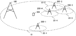
- FIG. 1 is a schematic diagram illustrating a configuration example of a communication system according to the first embodiment.
- the communication system according to the present embodiment includes a low-power base station 200-x in a macro cell 10 (macro area) whose communication area is a wide area by a macro cell base station (first base station) 100.
- X is an arbitrary positive integer, and in the example of the present embodiment, 1 ⁇ x ⁇ 4) is configured with a small cell 20-x having a communication area.
- the terminal 300 is assumed to be present at an arbitrary position in the macro area as shown in FIG.
- the difference between the macrocell base station and the low power base station is based on the difference in transmission power, but is not limited to this.
- the communication area (cell) covered may differ between base stations included in a small cell, such as a picocell base station and a femtocell base station, the present invention can also be applied to such an environment.
- the macro cell base station and the low power base station are connected by a backhaul line, and a wire such as an optical fiber or an X2 interface may be used, or a radio such as a relay base station may be used.
- a method is described in which a macro cell base station covering a macro area manages connection of a terminal and assists connection to a low power base station.
- the macro cell base station is distinguished from the low power base station. May be distinguished not only by the transmission power but also by a backward compatible cell that supports the already service-in method and a newly defined non-backward compatible cell.
- the communication system of FIG. 1 is assumed as an example. However, the present embodiment can be applied to any communication system in which at least one small cell is configured in a macro cell. , The number of terminals, the type of cell (eg, pico cell, femto cell, etc.), the type of base station, etc. are not limited to this embodiment.
- the macro cell base station 100 may be a communication system that manages connection with the terminal 300 in units of sectors.
- FIG. 2 is a schematic diagram illustrating a configuration example of a communication system in which the macro cell base station 100 manages connection with the terminal 300 in units of sectors. As shown in FIG.
- the macro cell 10 is composed of sectors in one direction of the macro cell base station 100, and at least one small cell 20 -x is arranged in the macro cell 10. These points are the same not only in the first embodiment but also in other embodiments.
- the small cell completely overlaps the macro cell.
- the small cell may partially overlap or may not overlap, and the present invention is not limited to this.
- each cell base station periodically synchronizes signals (SS: Synchronization Signal), tracking signals, measurement signals (for example, cell-specific). Reference signal, common pilot signal, etc.).
- SS Synchronization Signal
- the synchronization signal is a signal for searching (cell search) for a carrier frequency and cell ID such as PSS (Primary SS) and SSS (Secondary SS) defined in 3GPP (The Third Generation Partnership project), for example. It is.
- the tracking signal is a signal for identifying the sample point of the received signal more accurately than the synchronization signal.
- the measurement signal is a signal for measuring reception quality. Note that all base stations do not necessarily have to transmit all these signals.
- the macrocell base station 100 uses a method in which the macrocell base station maintains backward compatibility, and the low-power base station uses a new method (for example, NCT (referred to as New Carrier Type in 3GPP))
- NCT referred to as New Carrier Type in 3GPP
- the macrocell base station 100 has a signal format that includes all signals, but the low-power base station 200-x uses a tracking signal.
- the signal format may include only the measurement signal, and the tracking signal and the measurement signal may be the same signal, and in the following, the tracking signal and the measurement signal have the same signal format. In the following, it is assumed that different frequencies are used for the macro cell base station and the low power base station, but this is not the only case. Not.
- the search for the carrier frequency and the search for the cell ID are defined as the cell search, and the identification of the sample point is defined as the synchronization. However, if the same processing is performed, the search is essentially the same. is there.
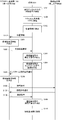
- FIG. 3 is a sequence diagram showing an example of a processing flow of the communication system in the present embodiment.
- a connected base station (second base station) represents a base station that becomes a new connection destination, and is one of the low-power base stations 200-x.
- the terminal 300 detects a synchronization signal transmitted from the macro cell base station 100 (that is, a synchronization signal for performing communication in the macro cell 10) among the synchronization signals transmitted from the respective base stations (step S101). At this time, the terminal 300 refers to the frequency allocation for each cell defined in the system, and detects the synchronization signal of the frequency used by the macro cell 10.
- the method of searching for the synchronization signal of the macro cell 10 includes a method of generating a replica of the synchronization signal using all candidate cell IDs and searching for a cell ID having the highest correlation with the received synchronization signal. Used. Further, the synchronization signal of the macro cell 10 may be determined from the difference in signal format between the macro cell 10 and the small cell 20-x. Furthermore, the terminal 300 connects to the macro cell base station 100 (step S102).
- the terminal 300 measures the position information (terminal information) of the terminal 300 (step S103).
- the position information may be information indicating the geographical position of the terminal 300 or information indicating a relative position.
- the information indicating the geographical position is, for example, information measured using GPS (Global Positioning System), and the information indicating the relative position is, for example, LTE (Long Term Evolution), LTE-A ( Information measured using a Positioning reference signal transmitted from the macrocell base station 100 as in the case of LTE-Advanced) may be used.
- LTE Long Term Evolution
- LTE-A Information measured using a Positioning reference signal transmitted from the macrocell base station 100 as in the case of LTE-Advanced
- reception quality with each base station measured using a cell-specific reference signal may be used.
- the process of step S103 may be performed before step S101 and step S102, and may be any timing at which the terminal 300 can measure position information.
- the terminal 300 notifies the macro cell base station 100 of the location information (Step S104).
- the macrocell base station 100 determines a connection base station based on the location information notified from the terminal 300 (step S105).
- the macro cell base station 100 may calculate the distance between the location information of the terminal 300 and each low power base station 200-x, and use the cell ID of the shortest power base station 200-x with the shortest distance as the connection base station information. preferable. For example, in FIG. 1, when the distance between the terminal 300 and the low power base station 200-4 is the shortest, the connected base station information is set as the cell ID of the small cell 20-4.
- the connection base station information is not limited to the cell ID as long as it is information that can identify the connection destination cell or base station.
- the macro cell base station 100 may measure the location information of the terminal 300 and determine a connection base station in consideration of the result. For example, the macro cell base station 100 measures position information using a reference signal and a control signal transmitted from the terminal 300. Thereby, the macro cell base station 100 can determine a connection base station using the position information notified from the terminal 300 and the position information measured by the own station.
- the macro cell base station 100 may determine the connection base station in consideration of the connection status of each base station in addition to the location information.
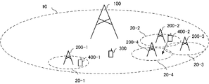
- FIG. 4 is a schematic diagram illustrating a configuration example of a communication system representing another aspect of the first embodiment.
- the terminals 400-1 and 400-2 are connected to the low power base station 200-1 and the low power base station 200-2, respectively, and the low power base stations 200-3 and 200-4 are connected. Is not connected to the terminal 300 among the low power base stations (the low power base station 200-3 and the low power base station 200-4) to which the terminal is not connected.
- a station is a connected base station.
- the macrocell base station 100 notifies the connection base station of a connection request (for example, a handover request) through the backhaul line (step S106).
- the connecting base station determines whether or not connection is possible, and notifies the macro cell base station 100 of permission notification (for example, handover request ACK / NACK) (step S107).
- the connection base station performs connection preparation such as scheduling when connection is possible.
- the macro cell base station 100 instructs the terminal 300 to change the connection destination from the macro cell base station 100 to the connection base station (step S108).
- the terminal 300 detects the synchronization signal and measurement signal of the connected base station (step S109).
- the method of detecting the signal of the connected base station may be the same as in step S101, or if the signal format is different, synchronization processing based on the signal format may be performed.
- the synchronization signal of the carrier frequency of the connected base station may be detected, or the signal of the connected base station may be determined from the difference in the cell ID of the connected base station, the signal format for each cell, or the like.
- the terminal 300 connects to the connected base station (step S110).
- the terminal 300 connects to the macro cell base station 100 and notifies the macro cell base station 100 of location information of the terminal 300. Further, the macro cell base station 100 sets the low power base station 200-x selected based on the distance from the terminal 300 among the low power base stations 200-x as a connection base station (new connection destination), and the terminal 300 is connected. The destination is switched from the macrocell base station 100 to the connected base station.
- the terminal needs to detect signals from all detectable base stations. However, if this embodiment is used, the terminal only needs to detect the synchronization signal from the macro cell base station and the measurement signal of the connected base station designated by the macro cell base station.
- the connection destination can be changed efficiently.
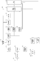
- FIG. 5 is a schematic block diagram showing a configuration example of the macro cell base station 100 and the low-power base station 200-x in the first embodiment.
- the macrocell base station 100 in this embodiment is demonstrated using FIG.
- the macrocell base station 100 includes a location information detection unit 101-1, a connection base station determination unit 101-2, an information data generation unit 101-3, a physical layer control unit 102, an encoding unit 103, a modulation unit 104, and a reference signal generation unit. 105, control signal generation unit 106, synchronization signal generation unit 107, resource mapping unit 108, IFFT unit 109, CP insertion unit 110, transmission unit 111, transmission antenna unit 112, reception antenna unit 121, reception unit 122, control information detection unit 123 and an information data detection unit 124.
- the location information detection unit 101-1, the connection base station determination unit 101-2, and the information data generation unit 101-3 are referred to as an upper layer 101.
- the base station 100 when a part or all of the base station 100 is formed into a chip to form an integrated circuit, a chip control circuit (not shown) for controlling each functional block is provided.
- a chip control circuit (not shown) for controlling each functional block is provided.
- the number of transmission antennas and the number of reception antennas are one, but there may be a plurality of antennas.
- the macro cell base station 100 receives a signal transmitted from the terminal 300 via the reception antenna unit 121.
- the signal received by the macrocell base station 100 includes a control signal, an uplink data signal, and the like.
- the control signal includes information regarding parameters of a transmission signal that the base station 100 transmits in the downlink.
- the information related to the parameters of the transmission signal includes a channel quality indicator (CQI: Channel Quality Indicator), the number of MIMO transmission ranks and the number of spatial multiplexing (RI: Rank Indicator), and other information related to downlink scheduling.
- Scheduling refers to determining at what time (timing) and in which frequency band when transmitting certain data, and scheduling information refers to information on the determined time and frequency band. For example, in LTE and LTE-A, it means determining to which resource block information data or the like is allocated.
- a resource block is a signal allocation unit configured by collecting a plurality of resource elements, which are minimum units for arranging a signal composed of one subcarrier and one OFDM symbol, in OFDM transmission.
- the control signal can also include position information.
- the control signal is transmitted using an uplink control channel (PUCCH: Physical Uplink Control Channel) or the like.
- the information required by the upper layer 101 is included in the uplink data signal.
- position information is included in the uplink data signal.
- the control signal of the upper layer 101 is transmitted using an uplink shared channel (PUSCH: Physical Uplink Shared Channel) or the like.
- the receiving unit 122 down-converts (radio frequency conversion) the received signal to a frequency band that can be subjected to digital signal processing such as signal detection processing, and further performs filtering processing. Also, the filtered signal is converted from an analog signal to a digital signal (A / D conversion: Analog to Digital conversion), a control signal is output to the control information detection unit 123, and an upstream data signal is output to the information data detection unit 124 To do.
- a / D conversion Analog to Digital conversion
- the control information detection unit 123 performs demodulation processing and decoding processing on the control signal input from the reception unit 122, detects control information, and outputs the control information to the physical layer control unit 102.
- the information data detection unit 124 performs demodulation processing, decoding processing, and the like on the uplink data signal input from the reception unit 122, detects the uplink information data, and transmits the uplink information data to the upper layer 101 (position information detection unit 101-1). Output.
- the uplink information data can include position information (step S104 in FIG. 3) transmitted from the terminal 300.
- the upper layer 101 acquires the uplink information data input from the information data detection unit 124.
- the upper layer includes an RRC (radio link control) layer.
- the location information detection unit 101-1 detects location information from the uplink information data notified from the terminal 300, and outputs the location information to the connected base station determination unit 101-2.
- the connection base station determination unit 101-2 determines connection base station information based on the position information input from the position information detection unit 101-1 (step S105 in FIG. 3).
- connection base station determination unit 101-2 notifies the connection base station of a connection request through the backhaul line (step S106 in FIG. 3), and a connection permission notification is received from the connection base station (step in FIG. 3). S107). Note that information exchange with other base stations such as step S106 and step S107 may be performed in the upper layer 101 of the macrocell base station and the upper layer 101 of the low-power base station through the backhaul line. It is not limited to the station determination unit 101-2.
- the macro cell base station 100 changes the connection destination of the terminal 300.
- the connected base station determining unit 101-2 outputs the connected base station information to the information data generating unit 101-3.
- the position information detection unit 101-1 outputs the transmission data to the information data generation unit 101-3.
- the information data generation unit 101-3 converts the input connection base station information and transmission data other than the connection base station information into a predetermined signal format to obtain downlink information data.
- the downlink information data includes data transferred from the MAC (Medium Access Control) layer to the physical layer and parameters set in the RRC (Radio Resource Control) layer that controls these parameters. Further, the information data generation unit 101-3 outputs the downlink information data to the physical layer control unit 102.
- MAC Medium Access Control
- RRC Radio Resource Control
- the macro cell base station 100 does not change the connection destination of the terminal 300.
- the position information detection unit 101-1 outputs transmission data other than the connection base station information to the information data generation unit 101-3, and the information data generation unit 101-3 receives information other than the input connection base station information. Only the transmission data is set as downlink information data, and the downlink information data is output to the physical layer control unit 102.
- the upper layer 101 generates downlink data information related to the connected base station information only when the macrocell base station 100 changes the connection destination of the terminal 300 (step S108 in FIG. 3).
- the physical layer control unit 102 outputs the downlink information data input from the information data generation unit 101-3 to the encoding unit 103. Further, the physical layer control unit 102 determines a reference signal generation pattern based on the control information input from the control information detection unit 123, and outputs the reference signal generation pattern to the reference signal generation unit 105. Further, the physical layer control unit 102 outputs the control information input from the control information detection unit 123 to the control signal generation unit 106.
- the encoding unit 103 performs error correction encoding on the downlink information data input from the information data generating unit 101-3.
- the encoding method used when the encoding unit 103 performs error correction encoding is, for example, turbo encoding, convolutional encoding, or low density parity check encoding (LDPC). coding) and the like.
- the encoding unit 103 performs rate matching processing on the encoded bit sequence in order to match the coding rate of the error correction encoded data sequence with the encoding rate corresponding to the data transmission rate. May be. Further, the encoding unit 103 may have a function of rearranging and interleaving the error correction encoded data series.
- the modulation unit 104 modulates the signal input from the encoding unit 103 to generate a modulation symbol.
- the modulation processing performed by the modulation unit 104 is, for example, BPSK (Binary Phase Shift Keying; two-phase phase modulation), QPSK (Quadrature Phase Shift Keying; four-phase phase modulation), QAM (Quadrature Amplitude Modulation; etc.).
- Modulating section 104 may have a function of rearranging generated modulation symbols and interleaving them.
- the reference signal generation unit 105 generates a reference signal (pilot signal) and outputs the generated reference signal to the resource mapping unit 108.
- the reference signal is used for estimating propagation path characteristics from the macrocell base station 100 to the terminal 300, measuring received power, positioning, and the like.
- the control signal generation unit 106 generates a control signal from the control information input from the physical layer control unit 102.
- the control signal may be subjected to error correction coding and modulation processing.
- the synchronization signal generation unit 107 generates a synchronization signal from the cell ID according to a rule determined in advance by the system.
- the resource mapping unit 108 maps modulation symbols, reference signals, control signals, and synchronization signals to resource elements based on the resource allocation information generated by the control information generation unit 106 (referred to as resource mapping).
- the IFFT unit 109 converts the frequency domain signal input from the resource mapping unit 108 into a time domain signal by performing a fast Fourier transform (IFFT: Inverse Fast Fourier Transform).
- IFFT section 109 may use another processing method, for example, inverse discrete Fourier transform (IDFT: Inverse Discrete Fourier Transform) instead of IFFT as long as it can convert a frequency domain signal into a time domain signal.
- IDFT Inverse Discrete Fourier Transform
- the CP insertion unit 110 adds an CP (Cyclic Prefix) to the time domain signal (referred to as a valid symbol) input from the IFFT unit 109 to generate an OFDM symbol.
- CP is a guard interval added for the purpose of avoiding multipath interference caused by delayed waves.
- the transmission unit 111 converts the OFDM symbol input from the CP insertion unit 110 from a digital signal to an analog signal (D / A conversion: Digital to Analog conversion). In addition, the transmission unit 111 generates a band-limited signal by band-limiting the generated analog signal by filtering processing, up-converts the generated band-limited signal to a radio frequency band, and transmits the signal from the transmission antenna unit 112.
- the low-power base station 200-x has the same configuration as the macrocell base station 100, but the processing of the upper layer 101 is different.
- the upper layer 101 is notified of a connection request from the macro cell base station 100 through the backhaul line (step S106 in FIG. 3).
- the upper layer 101 determines whether or not the terminal 300 can be connected, and notifies the macro cell base station 100 of a permission notification (handover request ACK / NACK) (step S107 in FIG. 3).
- the information data generation unit 101-3 Uses only the data transmitted from the higher layer 101 to the terminal 300 as downlink information data, and outputs the downlink information data to the physical layer control unit 102.
- FIG. 6 is a schematic block diagram illustrating a configuration example of the terminal 300 according to the first embodiment.
- the terminal 300 includes a reception antenna unit 151, a reception unit 152, a synchronization unit 153, a CP removal unit 154, a control information detection unit 155, an FFT unit 156, a channel estimation unit 157, a channel compensation unit 158, a demodulation unit 159, and a decoding unit. 160, a position information measurement unit 161, a reception quality calculation unit 162, a physical layer control unit 163, an upper layer 164, a control signal generation unit 171, a data signal generation unit 172, a transmission unit 173, and a transmission antenna unit 174.
- a chip control circuit (not shown) for controlling each functional block is provided.
- the number of transmitting antennas and the number of receiving antennas are one, but the number of antennas may be plural.
- the terminal 300 receives signals transmitted from the macrocell base station 100 and the low power base station 200-x via the reception antenna unit 151.
- the receiving unit 152 down-converts the radio frequency signal input from the receiving antenna unit 151 into a frequency band in which digital signal processing is possible, and further performs filtering processing. Further, the reception unit 152 performs A / D conversion on the signal subjected to the filtering process from an analog signal to a digital signal, and outputs the converted digital signal to the synchronization unit 153.
- the receiving unit 152 When detecting the synchronization signal of the macro cell 10, the receiving unit 152 detects the radio frequency signal by matching the radio frequency with the frequency assigned to the macro cell.
- the synchronization signal generation unit 165 generates a synchronization signal corresponding to the macro cell in advance.
- the synchronization unit 153 performs synchronization from the signal input from the reception unit 152, and outputs the received signal to the CP removal unit 154 when the synchronization is completed.
- CP removing section 154 removes the CP from the signal output from the receiving section in order to avoid distortion due to the delayed wave, and outputs the removed signal to FFT section 156.
- the FFT unit 156 performs a fast Fourier transform (FFT) that converts the signal input from the CP removal unit 154 from a time domain signal to a frequency domain signal, and sends the modulation symbol and the reference signal to the propagation path estimation unit 157.
- the control signal is output to the control information detector 155.
- the FFT unit 156 may perform other methods such as discrete Fourier transform (DFT: Discrete Fourier Transform) as long as the signal can be converted from the time domain to the frequency domain.
- DFT discrete Fourier transform
- the propagation path estimation unit 157 demaps the reference signal (pilot signal for propagation path estimation) included in the signal output from the FFT unit 156, and performs propagation path estimation using the pilot signal. Also, the propagation path estimation unit 157 outputs the estimated propagation path information to the propagation path compensation unit 158, the position information measurement unit 161, and the reception quality calculation unit 162.
- the control information detection unit 155 detects control information included in the signal output from the reception unit 152. In addition, the control information detection unit 155 extracts various information such as resource block allocation information, MCS information, HARQ information, and TPC information included in the control information. Then, various extracted information is detected and output to the demodulator 159 and the decoder 160.
- the propagation path compensation unit 158 Based on the propagation path estimation value input from the propagation path estimation unit 157, the propagation path compensation unit 158 performs ZF (Zero Forcing) equalization, MMSE (Minimum Mean Square Error) equalization, etc. Using a method, a weighting factor for correcting propagation path distortion due to fading is calculated, and propagation path compensation is performed on the input modulation symbol.
- ZF Zero Forcing
- MMSE Minimum Mean Square Error
- the demodulation unit 159 performs demodulation processing on the signal after propagation path compensation input from the channel compensation unit 158.
- the demodulation process may be either a hard decision (calculation of a coded bit sequence) or a soft decision (calculation of a coded bit LLR).
- the decoding unit 160 performs error correction decoding processing on the demodulated encoded bit sequence (or encoded bit LLR) output from the demodulating unit 159, calculates downlink information data, and performs physical layer control on the downlink information data. To the unit 163. At this time, the decoded information data includes connection base station information.
- This error correction decoding method is a method corresponding to error correction coding such as turbo coding and convolution coding performed by a connected base station. Either a hard decision or a soft decision can be applied to the error correction decoding process.
- the decoding unit 160 performs a deinterleaving process corresponding to the interleaving on the input coded bit sequence before performing the error correction decoding process. Then, the decoding unit 160 performs error correction decoding processing on the signal that has been subjected to deinterleaving processing.
- the position information measurement unit 161 measures the position information of the terminal 300 based on the propagation path information input from the propagation path estimation unit 157 (step S103 in FIG. 3), and outputs the position information to the physical layer control unit 163. .
- the position information is not limited to the propagation path information, and may be calculated by other methods.
- the reception quality calculation unit 162 calculates reception quality based on the propagation path information input from the propagation path estimation unit 157, and outputs the reception quality to the physical layer control unit 163.
- the physical layer control unit 163 outputs the input downlink information data (connection base station information and the like) and position information to the upper layer 164. Also, the physical layer control unit 163 outputs the received reception quality and the like as control information to the control signal generation unit 171. Of the information input to the physical layer control unit 163, the information managed by the upper layer 164 may be output to the upper layer 164.
- the allocation of information managed by the physical layer control unit 163 and the upper layer 164 is as follows. It is not limited to this.
- the upper layer 164 uses the data and position information to be transmitted to the upper layer 101 as uplink information data, and outputs the uplink information data to the data signal generation unit 172.
- the control signal generator 171 performs error correction coding and modulation mapping on the input control information, and generates a control signal.
- the data signal generation unit 172 performs error correction coding and modulation mapping on the input uplink information data, and generates an uplink data signal.
- the signal including the control signal input from the control signal generation unit 171 and the uplink data signal input from the data signal generation unit 172 is D / A converted by the transmission unit 173 and is increased to a frequency band that can be transmitted in the uplink.
- the signal is converted and transmitted to the base station of the connected cell via the transmission antenna unit 174.
- the synchronization signal generation unit 165 generates a synchronization signal based on the input connection base station information and outputs the synchronization signal to the synchronization unit 153. As a result, in the next reception process, a signal from the base station indicated in the connected base station information can be detected.
- step S101 to S104 of FIG. 3 the receiving unit 152 performs a cell search using the frequency of the macro cell 10 and receives a signal transmitted from the macro cell base station 100 in steps S101 to S104 in FIG. Then, the synchronization unit 153 performs synchronization with the synchronization signal (step S101 in FIG. 3). At this time, the cell ID determined to have the highest received power is notified to the upper layer 164, and the connection to the macrocell base station 100 is completed (step S102 in FIG. 3). Further, the position information measuring unit 161 measures the position information from the reference signal included in the received signal (step S103 in FIG. 3). Further, the data signal generation unit 172 generates an uplink data signal including the position information, and transmits the position information to the macrocell base station 100 via the transmission antenna 174 (step S104 in FIG. 3).
- the receiving unit 152 receives a signal transmitted from the macrocell base station 100 using the frequency of the macrocell 10 (step S108 in FIG. 3).
- the synchronization unit 153 does nothing, although not shown.
- the connected base station information included in the downlink information data is output to the synchronization signal generating section 165, and the synchronization signal generating section 165 searches for the connected base station by generating a synchronization signal corresponding to the connected base station information.
- the small cell base station 200-x designated by the macro cell base station 100 can be connected (steps S109 and S110 in FIG. 3).
- the terminal 300 is connected to the macro cell base station 100 and notifies the macro cell base station 100 of the location information of the terminal 300. Further, the macro cell base station 100 determines a connection base station based on the notified position information, and the terminal 300 switches the connection destination from the macro cell base station 100 to the connection base station. As a result, terminal 300 only needs to detect the synchronization signal from the macro cell base station and the measurement signal of the connected base station, so that signal detection processing can be reduced and the connection destination can be changed efficiently. (Second Embodiment)
- FIG. 7 is a sequence diagram illustrating an example of a processing flow of the communication system in the present embodiment.
- the configurations of the communication system, macrocell base station 100, low power base station 200-x, and terminal 300 in this embodiment are the same as those in the first embodiment. Only differences from the first embodiment will be described below.
- steps S101 to S104, and steps S106 to S110 are the same as those in the first embodiment.
- the macrocell base station 100 determines a candidate base station based on the location information notified from the terminal 300 (step S301).
- the candidate base station represents a plurality of base stations that are candidates for the connected base station, and the candidate base station calculates the distance between the location information of the terminal 300 and each low-power base station 200-x,
- the cell IDs of a plurality of low-power base stations 200-x that are close to each other are preferably used as candidate base station information. For example, in FIG. 1, two cells that are close to the terminal 300 are selected, and the candidate base station information is set as cell IDs 20-1 and 20-4.
- the number of candidate base stations may be set in advance, or a threshold may be set in advance, and a base station where the distance between the terminal 300 and the low power base station 200-x is within the threshold may be set as the candidate base station.
- the candidate base station information is not limited to the cell ID as long as it is information that can identify the connection destination cell or base station.
- the macro cell base station 100 may measure the connection status of the terminal 300 and determine a candidate base station in consideration of the result.
- the macrocell base station 100 requests reception quality from the terminal 300 (step S302).
- the terminal 300 detects the measurement signal transmitted from the candidate base station among the measurement signals transmitted from the base stations of the neighboring cells (step S303).
- Terminal 300 measures long-term reception quality from the measurement signal for each cell (step S304).
- the reception quality may be anything that represents the reception quality of the signal transmitted from each base station to the terminal 300, such as reception power, reception SINR (Signal to Interference plus Noise power Ratio), etc.
- the observed reception quality is preferred.
- the terminal 300 notifies the macro cell base station 100 of the long term reception quality for each cell (step 305).
- the macro cell base station 100 determines a connection base station based on the long term reception quality for each cell notified from the terminal 300 (step S306).
- the macrocell base station 100 desirably selects the small cell 20-x having the best reception quality. For example, when the received power of the low power base station 200-1 and the low power base station 200-4 is 1 [dBm] and 4 [dBm], respectively, the base station with the highest received power (the best long term reception quality) The low-power base station 200-4 as a connection base station.
- the macro cell base station 100 instructs the terminal 300 to change the connection destination from the macro cell base station 100 to the connection base station determined in step S306 (step S106).
- FIG. 8 is a schematic block diagram illustrating a configuration example of the terminal 300 in the second embodiment.
- FIG. 8 has the same configuration as FIG. 6 except that the reception quality calculation unit 162 measures each reception quality from the measurement signal transmitted from the candidate base station and outputs it to the upper layer.
- the upper layer 164 is a point that calculates the long term reception quality from the input reception quality, outputs it to the data signal generation unit 172, and transmits it to the macrocell base station 100.
- the long term reception quality is obtained by filtering (for example, averaging) the reception quality measured by the reception quality calculation unit 162.
- the macro cell base station 100 determines a candidate base station to be a connection destination candidate based on the position information, and sets the long-term reception quality of the connection candidate base station notified from the terminal 300. Based on this, a connection base station is determined. Since the reception quality is determined by the communication status with other terminals and the like, it is possible to determine a more optimal connection destination as compared with the case where the connection base station is determined only by the position information. Therefore, when this embodiment is used, the capacity of the macro area can be improved while reducing the signal detection processing necessary for the cell search. (Third embodiment)
- FIG. 9 is a schematic diagram illustrating a configuration example of a communication system according to the third embodiment.
- the terminal 400-2 moves in the direction of the arrow, and from the small cell 20-2 covered by the small power base station 200-2 (second base station), the small power base station 200-4 (second power station).
- the small power base station 200-4 second power station.
- the terminal 400-2 is connected to the low power base station 200-2 based on the method of the first embodiment or the second embodiment.
- FIG. 10 is a sequence diagram illustrating an example of a processing flow of the communication system according to the present embodiment.
- terminal 400-2 is already connected to low-power base station 200-2, and the connection is changed to low-power base station 200-4.
- a measurement signal is received from the low power base station 200-2, and the reception quality is measured (step S401).
- terminal 400-2 determines that it is better to connect to another base station, and generates position information (step S402).
- the location information is transmitted to the macro base station 100 (step S403).
- the base station 100 determines a connection base station (step S404), and transmits information of the determined connection base station to the terminal 400-2 (step S405).
- a synchronization signal of the connected base station is generated based on the notified information of the connected base station (step S406).
- the low power base station 20-4 transmits a measurement signal (step S407), and the terminal 400-2 synchronizes with the measurement signal (step S408) and connects to the connected base station (step S409).
- the low power base station 200-4 may periodically or autonomously transmit the measurement signal transmitted in step S407, and the transmission timing of the measurement signal of the low power base station is not limited.
- the terminal determines handover between small cells. For example, when it is determined that a low-power base station should connect to another base station, the macro cell base station reconnects. You may request to make a decision.
- the program that operates in the base station and the terminal related to the present invention is a program (a program that causes a computer to function) that controls the CPU and the like so as to realize the functions of the above-described embodiments related to the present invention.
- Information handled by these devices is temporarily stored in the RAM at the time of processing, then stored in various ROMs and HDDs, read out by the CPU, and corrected and written as necessary.
- a recording medium for storing the program a semiconductor medium (for example, ROM, nonvolatile memory card, etc.), an optical recording medium (for example, DVD, MO, MD, CD, BD, etc.), a magnetic recording medium (for example, magnetic tape, Any of a flexible disk etc. may be sufficient.
- the processing is performed in cooperation with the operating system or other application programs.
- the functions of the invention may be realized.
- the program when distributing to the market, can be stored and distributed on a portable recording medium, or transferred to a server computer connected via a network such as the Internet.
- the storage device of the server computer is also included in the present invention.
- part or all of the base station and the terminal in the above-described embodiment may be realized as an LSI that is typically an integrated circuit.
- Each functional block of the base station and the terminal may be individually chipped, or a part or all of them may be integrated into a chip.
- the method of circuit integration is not limited to LSI, and may be realized by a dedicated circuit or a general-purpose processor. When each functional block is integrated, an integrated circuit controller for controlling them is added.
- the method of circuit integration is not limited to LSI, and may be realized by a dedicated circuit or a general-purpose processor.
- an integrated circuit based on the technology can also be used.
- the terminal of the present invention is not limited to the above-described embodiment.
- the terminal of the present invention is not limited to application to a mobile station device, but is a stationary or non-movable electronic device installed indoors or outdoors, such as AV equipment, kitchen equipment, cleaning / washing equipment, Needless to say, it can be applied to air-conditioning equipment, office equipment, vending machines, and other daily life equipment.
- the present invention is suitable for use in wireless base stations, wireless terminals, wireless communication systems, and wireless communication methods.
Landscapes
- Engineering & Computer Science (AREA)
- Computer Networks & Wireless Communication (AREA)
- Signal Processing (AREA)
- Mobile Radio Communication Systems (AREA)
Abstract
Description
第一の基地局に端末情報を送信し、該第一の基地局から通知された情報に基づいて第二の基地局との通信を開始することを特徴とする。
(第1の実施形態)
(第2の実施形態)
(第3の実施形態)
100 マクロセル基地局
20-1、20-2、20-3、20-4 スモールセル
200-1、200-2、200-3、200-4 小電力基地局
300 端末
101 上位レイヤ
101-1 位置情報検出部
101-2 接続基地局決定部
101-3 情報データ生成部
102 物理レイヤ制御部
103 符号化部
104 変調部
105 参照信号生成部
106 制御信号生成部
107 同期信号生成部
108 リソースマッピング部
109 IFFT部
110 CP挿入部
111 送信部
112 送信アンテナ部
121 受信アンテナ部
122 受信部
123 制御情報検出部
124 情報データ検出部
151 受信アンテナ部
152 受信部
153 同期部
154 CP除去部
155 制御情報検出部
156 FFT部
157 伝搬路推定部
158 伝搬路補償部
159 復調部
160 復号部
161 位置情報測定部
162 受信品質算出部
163 物理レイヤ制御部
164 上位レイヤ
165 同期信号生成部
171 制御信号生成部
172 データ信号生成部
173 送信部
174 送信アンテナ部
Claims (17)
- 基地局と通信を行う端末であって、
第一の基地局に端末情報を送信し、該第一の基地局から通知された情報に基づいて第二の基地局との通信を開始することを特徴とする端末。 - 前記端末情報は、位置情報であることを特徴とする請求項1に記載の端末。
- 前記位置情報は、GPSにより得られる情報であることを特徴とする請求項2に記載の端末。
- 前記位置情報は、測位用の参照信号により得られる情報であることを特徴とする請求項2に記載の端末。
- 前記端末情報は、受信品質であることを特徴とする請求項1に記載の端末。
- 請求項1記載の端末であって、
前記第一の基地局との通信を開始する際には、セルサーチと同期を行い、前記第二の基地局との通信が指示された場合には、同期を行うことを特徴とする端末。 - 請求項1記載の端末であって、
前記第一の基地局から通知された複数の第二の基地局と同期を行い、受信品質を測定することを特徴とする端末。 - 測定された全ての第二の基地局の受信品質に関する情報を前記第一の基地局に通知することを特徴とする請求項7記載の端末。
- 請求項1記載の端末であって、
前記第二の基地局との通信における受信品質が所定の値以下となった場合に、前記第一の基地局に端末情報を送信し、前記第一の基地局から送信された情報に基づいて第三の基地局と通信を開始することを特徴とする端末。 - 端末を制御する基地局であって、
前記端末から通知された端末情報を受信し、接続基地局情報を該端末へ送信することを特徴とする基地局。 - 前記端末情報は、位置情報であることを特徴とする請求項10に記載の基地局。
- 前記位置情報は、GPSにより得られる情報であることを特徴とする請求項11記載の基地局。
- 前記位置情報は、測位用の参照信号により得られる情報であることを特徴とする請求項11記載の基地局。
- 前記端末情報は、受信品質であることを特徴とする請求項10に記載の基地局。
- 前記端末情報から位置情報を把握し、該位置情報に基づいて、前記接続基地局情報を決定することを特徴とする請求項10に記載の基地局。
- 前記接続基地局情報は、前記端末と第二の基地局との距離に基づいて決定することを特徴とする請求項10に記載の基地局。
- 端末を制御する基地局であって、
前記端末から通知された端末情報を受信し、候補基地局を該端末へ送信し、該端末から受信品質を受信し、接続基地局情報を該端末へ送信することを特徴とする基地局。
Priority Applications (2)
| Application Number | Priority Date | Filing Date | Title |
|---|---|---|---|
| JP2014538316A JPWO2014050449A1 (ja) | 2012-09-25 | 2013-09-03 | 基地局および端末 |
| US14/428,040 US20150257072A1 (en) | 2012-09-25 | 2013-09-03 | Base station and terminal |
Applications Claiming Priority (2)
| Application Number | Priority Date | Filing Date | Title |
|---|---|---|---|
| JP2012210880 | 2012-09-25 | ||
| JP2012-210880 | 2012-09-25 |
Publications (1)
| Publication Number | Publication Date |
|---|---|
| WO2014050449A1 true WO2014050449A1 (ja) | 2014-04-03 |
Family
ID=50387858
Family Applications (1)
| Application Number | Title | Priority Date | Filing Date |
|---|---|---|---|
| PCT/JP2013/073617 Ceased WO2014050449A1 (ja) | 2012-09-25 | 2013-09-03 | 基地局および端末 |
Country Status (3)
| Country | Link |
|---|---|
| US (1) | US20150257072A1 (ja) |
| JP (1) | JPWO2014050449A1 (ja) |
| WO (1) | WO2014050449A1 (ja) |
Cited By (1)
| Publication number | Priority date | Publication date | Assignee | Title |
|---|---|---|---|---|
| CN116318600A (zh) * | 2023-05-19 | 2023-06-23 | 广州世炬网络科技有限公司 | 终端位置检测方法、装置、基站及存储介质 |
Families Citing this family (2)
| Publication number | Priority date | Publication date | Assignee | Title |
|---|---|---|---|---|
| JP2015115887A (ja) * | 2013-12-13 | 2015-06-22 | 富士通株式会社 | 基地局及びセル選択方法 |
| CN105187339B (zh) * | 2014-06-06 | 2018-12-07 | 华为技术有限公司 | 一种双选信道的补偿方法、系统及相关装置 |
Citations (3)
| Publication number | Priority date | Publication date | Assignee | Title |
|---|---|---|---|---|
| WO2009067700A1 (en) * | 2007-11-21 | 2009-05-28 | Qualcomm Incorporated | Source initiated communication handover |
| WO2009110565A1 (ja) * | 2008-03-05 | 2009-09-11 | 株式会社エヌ・ティ・ティ・ドコモ | 移動通信システム及びネットワーク装置 |
| WO2010048583A2 (en) * | 2008-10-23 | 2010-04-29 | Zte (Usa) Inc. | Femto cell handover in wireless communications |
Family Cites Families (3)
| Publication number | Priority date | Publication date | Assignee | Title |
|---|---|---|---|---|
| US5267261A (en) * | 1992-03-05 | 1993-11-30 | Qualcomm Incorporated | Mobile station assisted soft handoff in a CDMA cellular communications system |
| US8630649B2 (en) * | 2008-10-31 | 2014-01-14 | Samsung Electronics Co., Ltd. | Terminal, method for handover thereof and supporting method for handover of base station |
| US8937937B2 (en) * | 2010-06-22 | 2015-01-20 | Telefonaktiebolaget Lm Ericsson (Publ) | Synchronization in heterogeneous networks |
-
2013
- 2013-09-03 US US14/428,040 patent/US20150257072A1/en not_active Abandoned
- 2013-09-03 WO PCT/JP2013/073617 patent/WO2014050449A1/ja not_active Ceased
- 2013-09-03 JP JP2014538316A patent/JPWO2014050449A1/ja active Pending
Patent Citations (3)
| Publication number | Priority date | Publication date | Assignee | Title |
|---|---|---|---|---|
| WO2009067700A1 (en) * | 2007-11-21 | 2009-05-28 | Qualcomm Incorporated | Source initiated communication handover |
| WO2009110565A1 (ja) * | 2008-03-05 | 2009-09-11 | 株式会社エヌ・ティ・ティ・ドコモ | 移動通信システム及びネットワーク装置 |
| WO2010048583A2 (en) * | 2008-10-23 | 2010-04-29 | Zte (Usa) Inc. | Femto cell handover in wireless communications |
Cited By (2)
| Publication number | Priority date | Publication date | Assignee | Title |
|---|---|---|---|---|
| CN116318600A (zh) * | 2023-05-19 | 2023-06-23 | 广州世炬网络科技有限公司 | 终端位置检测方法、装置、基站及存储介质 |
| CN116318600B (zh) * | 2023-05-19 | 2023-08-22 | 广州世炬网络科技有限公司 | 终端位置检测方法、装置、基站及存储介质 |
Also Published As
| Publication number | Publication date |
|---|---|
| JPWO2014050449A1 (ja) | 2016-08-22 |
| US20150257072A1 (en) | 2015-09-10 |
Similar Documents
| Publication | Publication Date | Title |
|---|---|---|
| JP5973673B2 (ja) | ユーザ機器、無線ネットワークノード及びそれらにおける方法 | |
| US11310769B2 (en) | Method, apparatus, and computer-readable medium for enhanced decoding of narrowband master information blocks (MIB-NB) | |
| US10206150B2 (en) | Electronic device in radio communications system and radio communications method | |
| CN111434146A (zh) | 用于辅助对波束/小区级别测量进行排序的测量报告配置 | |
| CN109246782B (zh) | 软小区网络中的切换 | |
| KR102267945B1 (ko) | 휴면 모드에서 다수의 셀들로부터 기준 신호 송신 | |
| CN104813602A (zh) | 新载波类型(nct)无线网络中用于跨载波准同位信令的装置和方法 | |
| WO2014181154A1 (en) | Measurements in a wireless system | |
| WO2014115734A1 (ja) | 無線通信システム、端末装置、基地局装置、無線通信方法および集積回路 | |
| JP2019519959A (ja) | 無線ネットワークノード、無線デバイス、および参照信号の構成のためのそれらにおける方法 | |
| JP2014072580A (ja) | 受信機および受信品質測定方法 | |
| US20130265901A1 (en) | Coordinating Communications in radio Service Areas | |
| US11601894B2 (en) | Network node and method for managing power of cell reference symbols | |
| US20150319620A1 (en) | Base station device, terminal device, communication system, transmission method, reception method, communication method and integrated circuit | |
| JP6483181B2 (ja) | 基地局装置 | |
| WO2014050449A1 (ja) | 基地局および端末 | |
| JP2014060638A (ja) | 通信システム、基地局、端末及び通信方法 | |
| WO2024053493A1 (ja) | 基地局の送信システム、無線端末、基地局のDistributed Unit、及びこれらの方法 | |
| WO2014069590A1 (ja) | 基地局および端末 | |
| EP3949223B1 (en) | Aligning resources of two radio access technologies | |
| JP2015122546A (ja) | 通信システム及び通信方法 |
Legal Events
| Date | Code | Title | Description |
|---|---|---|---|
| 121 | Ep: the epo has been informed by wipo that ep was designated in this application |
Ref document number: 13840344 Country of ref document: EP Kind code of ref document: A1 |
|
| ENP | Entry into the national phase |
Ref document number: 2014538316 Country of ref document: JP Kind code of ref document: A |
|
| WWE | Wipo information: entry into national phase |
Ref document number: 14428040 Country of ref document: US |
|
| NENP | Non-entry into the national phase |
Ref country code: DE |
|
| 122 | Ep: pct application non-entry in european phase |
Ref document number: 13840344 Country of ref document: EP Kind code of ref document: A1 |