WO2014050263A1 - デジタル画像処理方法および撮影装置 - Google Patents
デジタル画像処理方法および撮影装置 Download PDFInfo
- Publication number
- WO2014050263A1 WO2014050263A1 PCT/JP2013/069283 JP2013069283W WO2014050263A1 WO 2014050263 A1 WO2014050263 A1 WO 2014050263A1 JP 2013069283 W JP2013069283 W JP 2013069283W WO 2014050263 A1 WO2014050263 A1 WO 2014050263A1
- Authority
- WO
- WIPO (PCT)
- Prior art keywords
- digital image
- image
- pixel
- processed
- value
- Prior art date
- Legal status (The legal status is an assumption and is not a legal conclusion. Google has not performed a legal analysis and makes no representation as to the accuracy of the status listed.)
- Ceased
Links
Images








Classifications
-
- G—PHYSICS
- G06—COMPUTING OR CALCULATING; COUNTING
- G06T—IMAGE DATA PROCESSING OR GENERATION, IN GENERAL
- G06T7/00—Image analysis
- G06T7/0002—Inspection of images, e.g. flaw detection
- G06T7/0012—Biomedical image inspection
-
- A—HUMAN NECESSITIES
- A61—MEDICAL OR VETERINARY SCIENCE; HYGIENE
- A61B—DIAGNOSIS; SURGERY; IDENTIFICATION
- A61B6/00—Apparatus or devices for radiation diagnosis; Apparatus or devices for radiation diagnosis combined with radiation therapy equipment
- A61B6/02—Arrangements for diagnosis sequentially in different planes; Stereoscopic radiation diagnosis
- A61B6/03—Computed tomography [CT]
- A61B6/032—Transmission computed tomography [CT]
-
- A—HUMAN NECESSITIES
- A61—MEDICAL OR VETERINARY SCIENCE; HYGIENE
- A61B—DIAGNOSIS; SURGERY; IDENTIFICATION
- A61B6/00—Apparatus or devices for radiation diagnosis; Apparatus or devices for radiation diagnosis combined with radiation therapy equipment
- A61B6/02—Arrangements for diagnosis sequentially in different planes; Stereoscopic radiation diagnosis
- A61B6/03—Computed tomography [CT]
- A61B6/037—Emission tomography
-
- A—HUMAN NECESSITIES
- A61—MEDICAL OR VETERINARY SCIENCE; HYGIENE
- A61B—DIAGNOSIS; SURGERY; IDENTIFICATION
- A61B6/00—Apparatus or devices for radiation diagnosis; Apparatus or devices for radiation diagnosis combined with radiation therapy equipment
- A61B6/52—Devices using data or image processing specially adapted for radiation diagnosis
- A61B6/5211—Devices using data or image processing specially adapted for radiation diagnosis involving processing of medical diagnostic data
- A61B6/5229—Devices using data or image processing specially adapted for radiation diagnosis involving processing of medical diagnostic data combining image data of a patient, e.g. combining a functional image with an anatomical image
- A61B6/5235—Devices using data or image processing specially adapted for radiation diagnosis involving processing of medical diagnostic data combining image data of a patient, e.g. combining a functional image with an anatomical image combining images from the same or different ionising radiation imaging techniques, e.g. PET and CT
-
- G—PHYSICS
- G06—COMPUTING OR CALCULATING; COUNTING
- G06T—IMAGE DATA PROCESSING OR GENERATION, IN GENERAL
- G06T5/00—Image enhancement or restoration
- G06T5/20—Image enhancement or restoration using local operators
-
- G—PHYSICS
- G06—COMPUTING OR CALCULATING; COUNTING
- G06T—IMAGE DATA PROCESSING OR GENERATION, IN GENERAL
- G06T5/00—Image enhancement or restoration
- G06T5/73—Deblurring; Sharpening
-
- G—PHYSICS
- G06—COMPUTING OR CALCULATING; COUNTING
- G06T—IMAGE DATA PROCESSING OR GENERATION, IN GENERAL
- G06T2207/00—Indexing scheme for image analysis or image enhancement
- G06T2207/10—Image acquisition modality
- G06T2207/10072—Tomographic images
- G06T2207/10081—Computed x-ray tomography [CT]
-
- G—PHYSICS
- G06—COMPUTING OR CALCULATING; COUNTING
- G06T—IMAGE DATA PROCESSING OR GENERATION, IN GENERAL
- G06T2207/00—Indexing scheme for image analysis or image enhancement
- G06T2207/10—Image acquisition modality
- G06T2207/10072—Tomographic images
- G06T2207/10088—Magnetic resonance imaging [MRI]
-
- G—PHYSICS
- G06—COMPUTING OR CALCULATING; COUNTING
- G06T—IMAGE DATA PROCESSING OR GENERATION, IN GENERAL
- G06T2207/00—Indexing scheme for image analysis or image enhancement
- G06T2207/10—Image acquisition modality
- G06T2207/10072—Tomographic images
- G06T2207/10104—Positron emission tomography [PET]
-
- G—PHYSICS
- G06—COMPUTING OR CALCULATING; COUNTING
- G06T—IMAGE DATA PROCESSING OR GENERATION, IN GENERAL
- G06T2207/00—Indexing scheme for image analysis or image enhancement
- G06T2207/10—Image acquisition modality
- G06T2207/10072—Tomographic images
- G06T2207/10108—Single photon emission computed tomography [SPECT]
-
- G—PHYSICS
- G06—COMPUTING OR CALCULATING; COUNTING
- G06T—IMAGE DATA PROCESSING OR GENERATION, IN GENERAL
- G06T2207/00—Indexing scheme for image analysis or image enhancement
- G06T2207/20—Special algorithmic details
- G06T2207/20024—Filtering details
- G06T2207/20028—Bilateral filtering
-
- G—PHYSICS
- G06—COMPUTING OR CALCULATING; COUNTING
- G06T—IMAGE DATA PROCESSING OR GENERATION, IN GENERAL
- G06T2207/00—Indexing scheme for image analysis or image enhancement
- G06T2207/20—Special algorithmic details
- G06T2207/20172—Image enhancement details
- G06T2207/20192—Edge enhancement; Edge preservation
-
- G—PHYSICS
- G06—COMPUTING OR CALCULATING; COUNTING
- G06T—IMAGE DATA PROCESSING OR GENERATION, IN GENERAL
- G06T2207/00—Indexing scheme for image analysis or image enhancement
- G06T2207/30—Subject of image; Context of image processing
- G06T2207/30004—Biomedical image processing
Definitions
- the present invention relates to a digital image processing method for processing a digital image and a photographing apparatus for performing photographing, and in particular, distance information between pixels and pixels related to a target pixel to be processed and neighboring pixels around the target pixel.
- the present invention relates to a technique for determining a filter coefficient based on value difference information.
- This kind of digital image processing method and imaging apparatus is a general medical imaging apparatus (CT (Computed Tomography) apparatus, MRI (Magnetic Resonance Imaging) apparatus, ultrasonic tomography apparatus, nuclear medicine tomography apparatus, etc.), non-destructive inspection CT Used in devices, digital cameras, digital video cameras, etc.
- CT Computer Tomography
- MRI Magnetic Resonance Imaging
- ultrasonic tomography apparatus ultrasonic tomography apparatus
- nuclear medicine tomography apparatus nuclear medicine tomography apparatus, etc.
- CT non-destructive inspection
- Non-Patent Document 1 A weighted average filter (average value filter, Gaussian filter, etc.) generally known as a smoothing filter is based on distance information between pixels regarding a target pixel to be processed and neighboring pixels around the target pixel.
- filter coefficient The coefficient of the filter kernel (hereinafter abbreviated as “filter coefficient”) is determined.
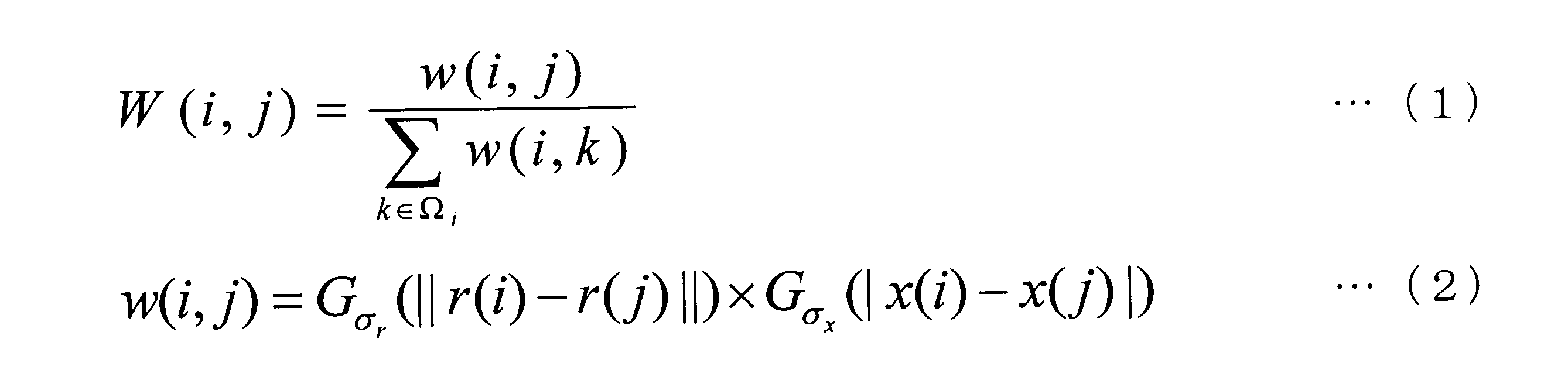
- the filter coefficient W is determined.
- i is the number of the target pixel
- j is the number of the neighboring pixel (adjacent pixel) with respect to the target pixel i
- w is the weighting factor of the neighboring pixel (adjacent pixel) j with respect to the target pixel i
- ⁇ i is the vicinity of the target pixel i Pixel set (see FIG.
- k is a variable belonging to the neighboring pixel set ⁇ i
- r (i) is the position vector of the pixel of interest i from the reference point
- r (j) is the neighborhood pixel j from the reference point position vector
- x (i) represents a pixel value of the pixel of interest i
- x (j) are neighboring pixel pixel value (adjacent pixels) j
- G ⁇ is a Gaussian function of standard deviation sigma, respectively.
- Parameters ⁇ r and ⁇ x (hereinafter referred to as “smoothing parameters”) that determine the degree of smoothing are set according to the properties of the image to be processed.
- the bilateral filter has a property of preserving edges (pixel value differences) in an image in order to reduce the filter coefficient of a pixel pair having a large pixel value difference.
- the bilateral filter described in the related art has the following problems. That is, the bilateral filter described in the related art tries to store a pixel pair having a large difference in pixel values as a “true edge (signal)” in the image to be processed.
- a “true edge (signal)” in the image to be processed.
- nuclear medicine images represented by PET images and SPECT (Single Photon Emission CT) images systematic and statistical fluctuations of pixel values (hereinafter collectively referred to as “noise”) are caused by noise. It is easy to erroneously determine “false edges” as true edges and save them.
- a false edge is erroneously detected as a true edge in the nuclear medicine image.
- the present invention has been made in view of such circumstances, and an object thereof is to provide a digital image processing method and a photographing apparatus capable of both maintaining spatial resolution and reducing noise.
- the digital image processing method determines a filter coefficient based on distance information between pixels and pixel value difference information regarding a target pixel to be processed and neighboring pixels around the target pixel.
- a digital image processing method for processing a digital image using the determined filter coefficient wherein A is a digital image to be processed and B is another image obtained by photographing the same object as the digital image A to be processed
- the filter coefficient is determined using information of the other digital image B, and the digital image A to be processed is processed.
- the filter processing can be performed without being influenced by the noise level of the digital image A to be processed by determining the filter coefficient using another digital image B as well. it can. As a result, it is possible to maintain both spatial resolution and reduce noise.
- the another digital image B described above is preferably a morphological image.
- the image to be processed is a digital image (nuclear medicine image) based on nuclear medicine data
- the nuclear medicine image has physiological information and is called a “functional image”. Lack of scientific information. Therefore, by using a morphological image having anatomical information as another digital image B, a morphological image having a high spatial resolution and a small noise is used, and a further effect is obtained.
- the function for determining the filter coefficient and using the difference between the pixel values as a variable is preferably a non-increasing function. If the pixel value difference value is small, smoothing can be performed by using a function having a large value, and if the pixel value difference value is large, a function having a small value can be used to store an edge having a large difference value. be able to.
- the “non-increasing function” means that the function value does not increase as the difference value of the pixel value increases, so that the function value is constant in the region of the difference value of some pixel values. May be. Therefore, as shown in FIG.
- a constant function having a value of “0” is also a non-increasing function.
- An example of the digital image processing method according to these inventions described above is to process the digital image A to be processed by determining the filter coefficient by the following equation. That is, in the digital image processing methods according to these inventions described above, i is the number of the target pixel, j is the number of the neighboring pixel with respect to the target pixel i, w is a weighting factor of the neighboring pixel j with respect to the target pixel i, ⁇ i is a set of neighboring pixels of the target pixel i, and k is the neighborhood A variable belonging to the pixel set ⁇ i , r (i) is a position vector of the pixel of interest i from the reference point, r (j) is a position vector of a neighboring pixel j from the reference point, and I b (i) is The pixel value of the target pixel i in the digital image B, I b (j) is the pixel value of the neighboring pixel j in the other digital image B, F is an arbitrary
- the weighting coefficient w (i, j) of the neighboring pixel j with respect to the pixel of interest i is also obtained using an arbitrary function H having the variable of the pixel value of the neighboring pixel in another digital image B as a variable.
- the filter coefficient W (i, j) is determined using the coefficient w (i, j).
- the filter coefficient W (i, j) is determined using another digital image B.
- the photographing apparatus is a photographing apparatus that performs photographing, and includes a filter determining unit that determines a filter coefficient in filtering processing, and a digital image processing unit that processes a digital image based on the photographed image.
- A is a digital image to be processed
- B is another digital image obtained by photographing the same object as the digital image A to be processed.
- the digital image processing means determines the filter coefficient based on the distance information between pixels and the difference information of the pixel value with respect to neighboring pixels around the pixel, and further using the information of the other digital image B. Is characterized in that the digital image A to be processed is processed using the filter coefficient determined by the filter determining means. That.
- the image capturing apparatus includes filter determining means for determining a filter coefficient in filtering processing and digital image processing means for processing a digital image based on the captured image. Based on the distance information between the pixels regarding the target pixel to be processed and the neighboring pixels around the target pixel and the difference information of the pixel value, the filter determination unit also uses information of another digital image B, After determining the filter coefficient, the digital image processing means processes the digital image A to be processed using the filter coefficient determined by the filter determining means. Thus, by determining the filter coefficient using another digital image B as well, the filter processing can be performed without being affected by the noise level of the digital image A to be processed. As a result, as described in the digital image processing method according to the present invention, both spatial resolution can be maintained and noise can be reduced.
- photographing means having a camera function for photographing a still image or a video function for photographing a moving image, and a digital image converting means for converting an image photographed by the photographing means into a digital image, Is preferably provided.
- the digital image converting means converts the image (analog image) photographed by the photographing means into a digital image while photographing a still image or photographing a moving image by the photographing means.
- the digital image processing means can process the converted digital image.
- An example of the imaging apparatus according to these inventions described above is a nuclear medicine diagnostic apparatus that performs nuclear medicine diagnosis, and the digital image processing means processes a digital image based on nuclear medicine data obtained by the nuclear medicine diagnosis.
- a digital image (nuclear medicine image) based on nuclear medicine data obtained by nuclear medicine diagnosis is a functional image and lacks anatomical information. Therefore, the digital image A to be processed is a digital image based on nuclear medicine data, and another digital image B is a morphological image.
- a morphological image having anatomical information as another digital image B, a morphological image with high spatial resolution and small noise is used. Therefore, even if the digital image to be processed is a nuclear medicine image that is a functional image lacking anatomical information, both spatial resolution can be maintained and noise can be reduced.
- the filter coefficient is determined using another digital image B, so that the filter processing can be performed without being affected by the noise level of the digital image A to be processed. It can be carried out. As a result, it is possible to maintain both spatial resolution and reduce noise.
- 1 is a side view of a PET-CT apparatus according to an embodiment.
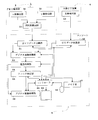
- 1 is a block diagram of a PET-CT apparatus according to an embodiment. It is the schematic of the specific structure of a gamma ray detector. It is a flowchart which shows the flow of a series of digital image processes including a filtering process. It is the figure which showed the neighborhood pixel set typically. It is an example of a non-increasing function using a difference between pixel values of neighboring pixels as a variable, which gives a weighting coefficient. It is a schematic diagram of a filter kernel. It is the figure which showed typically the neighborhood pixel set which concerns on a modification. It is an original image used for demonstration data (simulation experiment).
- FIG. 5 shows the result of filtering by a bilateral filter as the conventional method 2.
- FIG. 5 shows the result of filtering by a bilateral filter as the conventional method 2.
- FIG. 5 shows the result of filtering by a bilateral filter as the conventional method 2.
- FIG. 5 shows the result of filtering by a bilateral filter as the conventional method 2.
- FIG. 5 shows the result of filtering by a bilateral filter as the conventional method 2.
- FIG. 5 shows the result of filtering by a bilateral filter as the conventional method 2.
- FIG. FIG. 5 shows the result of filtering by a bilateral filter as the conventional method 2.
- FIG. FIG. 5 shows the result of filtering by a bilateral filter as the conventional method 2.
- FIG. 5 shows the result of filtering by a bilateral filter as the conventional method 2.
- FIG. FIG. 5 shows the result of filtering by a bilateral filter as the conventional method 2.
- FIG. It is the processing result of the filtering by the proposal method (bilateral filter using a form image) of a present Example. It is the processing result of the filtering by the proposal method (bilateral filter using a form image) of a present Example. It is the processing result of the filtering by the proposal method (bilateral filter using a form image) of a present Example. It is the processing result of the filtering by the proposal method (bilateral filter using a form image) of a present Example. It is the processing result of the filtering by the proposal method (bilateral filter using a form image) of a present Example. It is the processing result of the filtering by the proposal method (bilateral filter using a form image) of a present Example. It is the processing result of the filtering by the proposal method (bilateral filter using a form image) of a present
- FIG. 1 is a side view of the PET-CT apparatus according to the embodiment
- FIG. 2 is a block diagram of the PET-CT apparatus according to the embodiment.
- a PET-CT apparatus in which a PET apparatus and an X-ray CT apparatus are combined will be described as an example of an imaging apparatus.
- the PET-CT apparatus 1 includes a top plate 2 on which a subject M in a horizontal posture is placed.
- the top plate 2 is configured to move up and down and translate along the body axis of the subject M.
- the PET-CT apparatus 1 includes a PET apparatus 3 for diagnosing the subject M placed on the top 2.
- the PET-CT apparatus 1 includes an X-ray CT apparatus 4 that acquires a CT image of the subject M.
- the PET-CT apparatus 1 corresponds to the imaging apparatus in this invention.
- the PET apparatus 3 includes a gantry 31 having an opening 31a and a ⁇ -ray detector 32 that detects ⁇ -rays generated from the subject M.
- the ⁇ -ray detector 32 is arranged in a ring shape so as to surround the body axis of the subject M, and is embedded in the gantry 31.
- the ⁇ -ray detector 32 includes a scintillator block 32a, a light guide 32b, and a photomultiplier tube (PMT) 32c (see FIG. 3).
- the scintillator block 32a includes a plurality of scintillators.
- the scintillator block 32a converts the ⁇ -rays generated from the subject M to which the radiopharmaceutical has been administered into light
- the light guide 32b guides the converted light
- the photomultiplier tube 32c photoelectrically converts the light into electricity. Output to signal.
- the ⁇ -ray detector 32 and the later-described X-ray detector 43 correspond to the imaging means in this invention. A specific configuration of the ⁇ -ray detector 32 will be described later with reference to FIG.
- the X-ray CT apparatus 4 includes a gantry 41 having an opening 41a.
- a gantry 41 In the gantry 41, an X-ray tube 42 for irradiating the subject M with X-rays and an X-ray detector 43 for detecting X-rays transmitted through the subject M are disposed.
- the X-ray tube 42 and the X-ray detector 43 are arranged so as to face each other, and the X-ray tube 42 and the X-ray detector 43 are covered in the gantry 41 by driving a motor (not shown). Rotate around the body axis of the specimen M.
- a flat panel X-ray detector (FPD) is adopted as the X-ray detector 43.
- FIG. 1 (a) the gantry 31 of the PET apparatus 3 and the gantry 41 of the X-ray CT apparatus 4 are separated from each other. However, as shown in FIG. 1 (a), the gantry 31 of the PET apparatus 3 and the gantry 41 of the X-ray CT apparatus 4 are separated from each other. However, as shown in FIG. 1 (a), the gantry 31 of the PET apparatus 3 and the gantry 41 of the X-ray CT apparatus 4 are separated from each other. However, as shown in FIG.
- the PET-CT apparatus 1 includes a console 5 in addition to the above-described top plate 2, PET apparatus 3, and X-ray CT apparatus 4.
- the PET apparatus 3 includes a coincidence circuit 33 in addition to the gantry 31 and the ⁇ -ray detector 32 described above.
- the console 5 includes a PET data collection unit 51, a CT data collection unit 52, a digital image conversion unit 53, a superimposition processing unit 54, a filter determination unit 55, a digital image processing unit 56, a memory unit 57, an input unit 58, and an output unit 59. And a controller 60.
- the digital image conversion unit 53 corresponds to the digital image conversion unit in the present invention
- the filter determination unit 55 corresponds to the filter determination unit in the present invention
- the digital image processing unit 56 corresponds to the digital image processing unit in the present invention. To do.
- the coincidence counting circuit 33 determines whether or not ⁇ rays are simultaneously detected by the ⁇ ray detector 32 (that is, coincidence counting).
- the PET data simultaneously counted by the coincidence circuit 33 is sent to the PET data collection unit 51 of the console 5.
- CT data based on X-rays detected by the X-ray detector 43 (data for X-ray CT) is sent to the CT data collection unit 52 of the console 5.
- the PET data collection unit 51 collects the PET data sent from the coincidence circuit 33 as an analog image (analog image for PET) taken by the PET apparatus 3.
- the analog image collected by the PET data collection unit 51 is sent to the digital image conversion unit 53.
- the CT data collection unit 52 collects the CT data sent from the X-ray detector 43 as an analog image (analog image for X-ray CT) taken by the X-ray CT apparatus 4.
- the analog image collected by the CT data collection unit 52 is sent to the digital image conversion unit 53.
- the digital image conversion unit 53 converts a captured image (analog image) into a digital image.
- the digital image conversion unit 53 converts the analog image for PET captured by the PET apparatus 3 and sent via the PET data collection unit 51 into a digital image, and converts the digital image for PET.
- PET image the analog image for PET captured by the PET apparatus 3 and sent via the PET data collection unit 51 into a digital image
- the digital image conversion unit 53 converts an X-ray CT analog image captured by the X-ray CT apparatus 4 and sent via the CT data collection unit 52 into a digital image, thereby converting the digital image for X-ray CT.
- CT image a digital image for X-ray CT.
- Each digital image (PET image, CT image) is sent to the superimposition processing unit 54.
- the superimposition processing unit 54 performs a superimposition process in which the PET image and the CT image converted into a digital image by the digital image conversion unit 53 are aligned with each other and superimposed.
- the CT image may be applied to the PET image as transmission data to perform absorption correction of the PET image.
- the PET image and CT image subjected to the superimposition processing by the superimposition processing unit 54 are sent to the filter determination unit 55 and the digital image processing unit 56.
- the filter determination unit 55 determines a filter coefficient in the filtering process.
- the filter coefficient is determined using the PET image and the CT image.
- the filter coefficient determined by the filter determination unit 55 is sent to the digital image processing unit 56.
- the digital image processing unit 56 processes a digital image based on the captured image.
- the digital image processing unit 56 processes the PET image photographed by the PET apparatus 3 and sent via the PET data collection unit 51, the digital image conversion unit 53, and the superimposition processing unit 54.
- the PET image processed by the digital image processing unit 56 and the CT image photographed by the X-ray CT apparatus 4 and sent via the CT data collection unit 52, the digital image conversion unit 53, and the superimposition processing unit 54 are used. Superposition processing for superimposing again may be performed.
- the memory unit 57 receives each image collected, converted, or processed by the PET data collection unit 51, the CT data collection unit 52, the digital image conversion unit 53, the superimposition processing unit 54, or the digital image processing unit 56 via the controller 60.
- the data related to the data and the data such as the filter coefficient determined by the filter determination unit 55 are written and stored, read out as necessary, and sent to the output unit 59 via the controller 60 for output.
- the memory unit 57 includes a storage medium represented by ROM (Read-only Memory), RAM (Random-Access Memory), and the like.
- the input unit 58 sends data and commands input by the operator to the controller 60.
- the input unit 60 includes a pointing device represented by a mouse, a keyboard, a joystick, a trackball, a touch panel, and the like.
- the output unit 59 includes a display unit represented by a monitor, a printer, and the like.
- the controller 60 performs overall control of each part constituting the PET-CT apparatus 1 according to the embodiment.
- the controller 60 includes a central processing unit (CPU).
- CPU central processing unit
- Data such as filter coefficients is written to the memory unit 57 via the controller 60 and stored, or sent to the output unit 59 for output.
- the output unit 59 is a display unit, output display is performed, and when the output unit 59 is a printer, output printing is performed.
- the ⁇ -rays generated from the subject M to which the radiopharmaceutical is administered are converted into light by the scintillator block 32a (see FIG. 3) of the corresponding ⁇ -ray detector 32 among the ⁇ -ray detectors 32, and the converted The photomultiplier 32c (see FIG. 3) of the ⁇ -ray detector 32 photoelectrically converts the light and outputs it as an electrical signal.
- the electric signal is sent to the coincidence counting circuit 33 as image information (pixel value).
- the coincidence circuit 33 checks the position of the scintillator block 32a (see FIG. 3) of the ⁇ -ray detector 32 and the incident timing of the ⁇ -ray, and two scintillator blocks 32a that are opposed to each other across the subject M. Only when ⁇ rays are incident at the same time (that is, when simultaneous counting is performed), the sent image information is determined as appropriate data.
- the coincidence counting circuit 33 treats the image information sent at that time as noise instead of ⁇ rays generated by the disappearance of the positron, and determines it as noise. Dismiss.
- the image information sent to the coincidence counting circuit 33 is sent to the PET data collecting unit 51 as PET data (emission data).
- the PET data collection unit 51 collects the sent PET data and sends it to the digital image conversion unit 53.
- the subject M is irradiated with X-rays from the X-ray tube 42, and the X-rays irradiated from the outside of the subject M and transmitted through the subject M are emitted.
- the X-ray detector 43 detects an X-ray by converting it into an electric signal.
- the electric signal converted by the X-ray detector 43 is sent to the CT data collecting unit 52 as image information (pixel value).
- the CT data collection unit 52 collects the distribution of the sent image information as CT data and sends it to the digital image conversion unit 53.
- the digital image conversion unit 53 converts an analog pixel value into a digital pixel value, so that an analog image for PET (PET data) sent from the PET data collection unit 51 is converted into a digital image for PET (PET image). And an analog image (CT data) for X-ray CT sent from the CT data acquisition unit 52 is converted into a digital image (CT image) for X-ray CT. Then, it is sent to the superimposition processing unit 54.
- FIG. 3 is a schematic diagram of a specific configuration of the ⁇ -ray detector.
- the ⁇ -ray detector 32 includes a scintillator block 32a configured by combining a plurality of scintillators that are detection elements having different decay times in the depth direction, a light guide 32b optically coupled to the scintillator block 32a, and a light guide And a photomultiplier tube 32c optically coupled to 32b.
- Each scintillator in the scintillator block 32a detects ⁇ -rays by emitting light by the incident ⁇ -rays and converting it to light.
- the scintillator block 32a does not necessarily need to be combined with scintillators having different decay times in the depth direction (r in FIG. 3). Further, although two layers of scintillators are combined in the depth direction, the scintillator block 32a may be configured by a single layer scintillator.
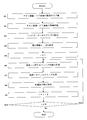
- FIG. 4 is a flowchart showing a flow of a series of digital image processing including filtering processing
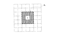
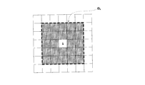
- FIG. 5 is a diagram schematically showing a neighborhood pixel set
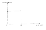
- FIG. 6 is a diagram of neighborhood pixels that give weighting factors.
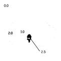
- FIG. 7 is an example of a non-increasing function using a difference between pixel values as a variable
- FIG. 7 is a schematic diagram of a filter kernel.
- A is a digital image to be processed
- B is another digital image obtained by photographing the same object as the digital image A to be processed (the region of interest of the subject M in this embodiment).
- a PET image that is a functional image will be described as an example of the digital image A to be processed
- a CT image that is a morphological image will be described as an example of another digital image B. Therefore, noise removal processing (filtering processing) of the PET image is performed also using information of the CT image.
- Step S1 Unification of Pixel Size of PET Image / CT Image
- the pixel size of the CT image is smaller than the pixel size of the PET image. Therefore, the pixel sizes of both images are unified in advance.
- the pixel size of the CT image is enlarged to match the pixel size of the PET image.
- “enlarging the pixel size” does not mean expanding one pixel size itself, but means integrating (combining) a plurality of pixels corresponding to the pixel size of the PET image into one pixel in the CT image. Please note that.
- Step S2 Superposition processing of PET image / CT image
- the superposition processing unit 54 (see FIG. 2) aligns the PET image and the CT image with each other.
- the alignment and superimposition processing here refers to both alignment and superimposition by displaying both images on the monitor of the output unit 59 (see FIG. 2) and manually moving both images with the input unit 58 (see FIG. 2). It should be noted that it is not the meaning of performing processing, but the meaning of defining the distribution of pixel values of both images by calculation and moving or parallelly moving both images by calculation so that the respective distributions coincide.
- Step S3 Setting of Filter Kernel Size
- the size of the filter kernel (filter coefficient) (neighboring pixel set ⁇ i ) is set for all pixels.
- the filter kernel has a square shape as shown in FIG.
- the pixel at the center of the filter kernel set to a square is the target pixel (to be processed) (see number i in FIG. 5), and the pixels around the filter kernel (see gray in FIG. 5) are the target pixel.
- a set of these neighboring pixels is a neighboring pixel set (see symbol ⁇ i in FIG. 5).
- the size of the filter kernel including the target pixel is the size of nine pixels with three pixel rows and three pixel columns, the remaining eight neighboring pixels excluding the target pixel are It becomes a pixel adjacent to the pixel of interest.
- Step S4 Setting of Weight Functions F and H Based on the distance information between the pixels and the pixel value difference information regarding the target pixel to be processed and neighboring pixels around the target pixel, the filter determination unit 55 (FIG. 2), the filter coefficient is determined using the information of another digital image (CT image in this embodiment) B. Specifically, real value functions F and H of the following formula (3) and the following formula (4) that influence the characteristics of the filter coefficient are set.
- F is an arbitrary function having the distance between pixels as a variable, and is a function that gives a weight depending on the distance between pixels (also referred to as a “weight function”).
- F is a Gaussian function with a standard deviation ⁇ r .
- r is the distance between the neighboring pixel and the pixel of interest, and as will be described later, r (i) is the position vector of the pixel of interest i from the reference point, and r (j) is the neighborhood pixel j of the reference point. Assuming that it is a position vector, r is represented by
- the reference point is not particularly limited, when a certain pixel is set as the origin, the origin may be used as the reference point, or the target pixel may be always used as the reference point. In any case, even in the case of the neighborhood pixel set ⁇ i shown in FIG. 5 even if the distance between the same adjacent pixel and the target pixel is the same as the adjacent pixel located at the upper right, upper left, lower right, or lower left with respect to the target pixel. The distance from the pixel is ⁇ 2 times the distance between the pixel of interest and the adjacent pixel located vertically and horizontally with respect to the pixel of interest.
- the Gaussian function is a normal distribution, since r is an absolute value and is always a positive real number, F is a non-increasing function.
- H is an arbitrary function whose variable is the difference between the pixel values of neighboring pixels in another digital image (CT image in this embodiment) B.
- H is the edge strength (adjacent pixel) of the CT image B.
- a function that gives a weight depending on the pixel value difference between the target pixel and the target pixel.
- H is a binary function (threshold value T a ) shown in FIG. In FIG.
- a (i) is the pixel value of the pixel of interest i in the CT image B, which is a morphological image
- a (j) is the pixel value of a neighboring pixel j in the CT image B, as described later
- as a variable is preferably a non-increasing function.
- the value is a function of the constant value difference value is the threshold T a following region of the pixel value is "1", at a higher than the difference value is the threshold value T a pixel value region as shown in FIG. 6 It may be a binary function that is a function of a constant of “0”.
- threshold T a was a function of the constant "1", as long as satisfying the a> 0, the value of a is limited to "1" Not.
- a threshold function is set to two or more (for example, T a ⁇ T b ), a>b> 0 is satisfied, and a pixel value difference value is equal to or smaller than the threshold value T a is a constant function having a value “a”.
- a function of the constant value "b" is a high threshold T b the following areas than the difference value is the threshold value T a pixel value, a value in a region higher than the difference value T b of the pixel values It may be a multi-value function that is a function of a constant of “0”.
- the function value does not necessarily have to be constant in a region with a difference value between some pixel values, and the function value may decrease smoothly and monotonously.
- the value of the function may be constant in the area with the difference value of the pixel values, and the value of the function may decrease smoothly and monotonously in the other areas.
- the filter determination unit 55 also uses the information of the CT image B to (3 ) And the following equation (4) determine the filter coefficient W.
- i is the number of the target pixel
- j is the number of the neighboring pixel (adjacent pixel) with respect to the target pixel i
- w is the weighting factor of the neighboring pixel (adjacent pixel) j with respect to the target pixel i
- ⁇ i is the vicinity of the target pixel i Pixel set (see FIG.
- k is a variable belonging to the neighboring pixel set ⁇ i
- r (i) is the position vector of the pixel of interest i from the reference point
- r (j) is the neighborhood pixel j from the reference point A position vector
- a (i) is the pixel value of the pixel of interest i in the CT image B which is a morphological image
- a (j) is the pixel value of a neighboring pixel (adjacent pixel) j in the CT image B
- F and H are arbitrary Represents a function (weight function).
- the weight functions F and H are preferably non-increasing functions.
- F is a Gaussian function with a standard deviation ⁇ r and H is a binary function as shown in FIG.
- W (i, k) is w variable k belonging to neighboring pixel set Omega i (i, k) the sum of) the formula was divided by the filter This is to normalize the coefficient W.
- the present embodiment is a method of an edge-preserving smoothing filter for a nuclear medicine image (PET image A in the present embodiment) using contour information of an organ included in a CT image B that is a morphological image as a priori information.
- the pixel value of the nuclear medicine image (PET image A) has physiological information as described above, and is a numerical value reflecting the organ function (metabolic ability, blood flow rate, etc.). Function is different. That is, the pixel value is considered to vary depending on the organ. Therefore, the filter coefficient W of the smoothing filter to be applied to the nuclear medicine image (PET image A) is set to pixel value information (
- the image information to be referred to is not a conventional nuclear medicine image itself but a high-resolution and low-noise morphological image (CT image), it depends on a false edge derived from noise included in the nuclear medicine image.
- CT image high-resolution and low-noise morphological image
- Step S7 Filtering process of pixel i
- the digital image processing unit 56 (see FIG. 2) is replaced by the filter determining unit 55 (see FIG. 2).
- the digital image (PET image in this embodiment) A to be processed is processed using the filter coefficient W determined in step 2). Thereby, the filtering process (calculation of the weighted average value) of the pixel of interest i is performed.
- Step S8 Saving the value after processing
- the value after filtering processing is written and stored in the memory area of the memory unit 57 (see FIG. 1) different from the PET image A (that is, the original image) before processing.
- the image is stored in a memory area different from that of the original image.
- Step S10 i ⁇ N N is the number of pixels, and it is determined whether i ⁇ N. If i ⁇ N, it is determined that the filtering process for all the pixels has not been completed, and the process returns to step S6, and steps S6 to S10 are looped, and steps S6 to S10 are performed until the filtering process for all the pixels is completed. Repeat. If i> N, it is determined that the filtering process has been completed for all pixels, and the series of digital image processes in FIG. 4 is terminated.
- the digital image to be processed (PET image in the present embodiment) is determined by determining the filter coefficient W also using another digital image (CT image in the present embodiment) B.
- Filtering can be performed without being affected by the noise level of A. As a result, it is possible to maintain both spatial resolution and reduce noise.
- the other digital image B described above is preferably a morphological image represented by a CT image B or the like as in the present embodiment.
- the image to be processed is a digital image (nuclear medicine image) based on nuclear medicine data
- the nuclear medicine image has physiological information, and “function image” It is called but lacks anatomical information. Therefore, by using a morphological image having anatomical information as another digital image (CT image) B, a morphological image (CT image B in this embodiment) having high spatial resolution and low noise is used. It will be more effective.
- a function (weighting function H in this embodiment) using a difference between pixel values (in this embodiment
- the “non-increasing function” means that the function value does not increase as the difference value of the pixel value increases, so that the function value is constant in the region of the difference value of some pixel values. May be. Therefore, as shown in FIG.
- a constant function having a value of “0” is also a non-increasing function.
- I b (i) is the pixel value of the pixel of interest i in another digital image B
- I b (j) is the pixel value of the neighboring pixel j in another digital image B.
- the weighting factor w (i, i, of the neighboring pixel j with respect to the pixel i of interest is also used by using an arbitrary function H whose variable is the difference between the pixel values of neighboring pixels in another digital image (CT image in this embodiment) B. j) is obtained, and the filter coefficient W (i, j) is determined using the weight coefficient w (i, j). Accordingly, the filter coefficient W (i, j) is determined using another digital image (CT image) B.
- the filter determination unit 55 that determines the filter coefficient in the filtering process, and the digital image based on the photographed image (PET in the present embodiment). And a digital image processing unit 56 for processing the image A).
- the filter determination unit 55 further generates another digital image (CT in this embodiment) based on the pixel distance information and the pixel value difference information regarding the target pixel to be processed and neighboring pixels around the target pixel.
- the image coefficient B is also used to determine the filter coefficient W, and the digital image processing unit 56 processes the digital image (PET image) A to be processed using the filter coefficient W determined by the filter determination unit 55. To do.
- the filter processing can be performed without being affected by the noise level of the digital image (PET image) A to be processed. it can.
- CT image digital image
- PET image digital image
- an imaging unit (a ⁇ -ray detector 32 and an X-ray detector 43 in this embodiment) having a camera function for capturing a still image or a video function for capturing a moving image; It is preferable to include a digital image conversion unit 53 that converts an image captured by the ⁇ -ray detector 32 into a digital image.
- a still image or moving image imaging unit ( ⁇ -ray detector 32 or X-ray detector) is provided.
- the digital image conversion unit 53 converts the image (analog image) captured by the imaging unit ( ⁇ -ray detector 32 or X-ray detector 43) into a digital image (PET image or CT image in this embodiment).
- the digital image processing unit 56 can process the converted digital image (CT image in this embodiment).
- a nuclear medicine diagnostic apparatus that performs nuclear medicine diagnosis is taken as an example of an imaging apparatus
- a PET-CT apparatus 1 that combines a PET apparatus and an X-ray CT apparatus is taken as an example of a nuclear medicine diagnostic apparatus.
- the digital image processing unit 56 preferably processes a digital image (PET image in this embodiment) based on nuclear medicine data obtained by nuclear medicine diagnosis.
- the digital image (nuclear medicine image) based on the nuclear medicine data obtained by the nuclear medicine diagnosis is a functional image and lacks anatomical information.
- a digital image (PET image in this embodiment) A to be processed is a digital image based on nuclear medicine data
- another digital image B is a morphological image (CT image B in this embodiment).
- CT image B a morphological image having high spatial resolution and small noise is used. Therefore, even if the digital image (PET image A) to be processed is a nuclear medicine image that is a functional image lacking anatomical information, both spatial resolution can be maintained and noise can be reduced.
- FIGS. 9 is an original image used for demonstration data (simulation experiment)
- FIG. 10 is a noisy image obtained by artificially adding noise to the original image of FIG. 9, and
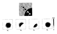
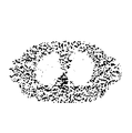
- FIG. It is a morphological image used for (experiment).
- experimental results of the conventional methods 1 and 2 are also shown.
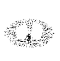
- FIGS. 12 to 14 show the filtering processing results by a general Gaussian filter as the conventional method 1
- FIGS. 15 to 20 show the filtering processing results by the bilateral filter as the conventional method 2.
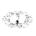
- FIGS. 26 shows a filtering processing result by the proposed method (bilateral filter using a morphological image) of the present embodiment.
- noise is artificially added to the original image shown in FIG. 9 to create an image with noise (see FIG. 10), and a filtering process using the conventional methods 1 and 2 and the proposed method of this embodiment. Went to each.
- the morphological image shown in FIG. 11 is used for the filtering process.
- Each image size is 128 ⁇ 128.
- the numerical values in the images of FIGS. 9 and 11 represent pixel values representing each region. Since the smoothing parameters ⁇ r and ⁇ x also have a half width, the smoothing parameters ⁇ r and ⁇ x are hereinafter referred to as “half width”.
- FIG. 15 to FIG. 20 show the filtering processing results by the bilateral filter as the conventional method 2.
- a Gaussian function of 4.0 pixels
- the Gaussian functions are 3.0 and 6.0. Therefore, the combination of the half-value widths ⁇ r and ⁇ x is a total of six patterns of processing results, which are shown in FIGS. 15 to 20, respectively.
- FIGS. 21 to 26 show the filtering processing results by the proposed method (bilateral filter using morphological images) of this embodiment.
- the width of the Gaussian function (half-value width ⁇ r ) with the distance between pixels as a variable and the width of the Gaussian function depending on the difference between the pixel values of the morphological image (half By adjusting the value width ⁇ x ), it is possible to maintain both spatial resolution and noise reduction.
- the proposed filtering method using a bilateral filter using a morphological image is the conventional filtering method (filtering method using a bilateral filter that uses a general Gaussian filter or the original image itself without using a morphological image). It was shown to be more effective.
- the present invention is not limited to the above embodiment, and can be modified as follows.
- a PET-CT apparatus in which a PET apparatus and an X-ray CT apparatus are combined has been described as an example.
- medical image apparatuses in general CT apparatus, MRI apparatus, ultrasonic tomography apparatus, (Nuclear medicine tomography apparatus, etc.), non-destructive inspection CT apparatus, digital camera, digital video camera, etc., or a single apparatus.
- the PET-CT apparatus in which the PET apparatus and the X-ray CT apparatus are combined has been described as an example of the imaging apparatus.
- the imaging apparatus may be applied to a single PET apparatus.
- a CT image obtained by an X-ray CT apparatus that is an external apparatus may be transferred to a PET apparatus, and the filter coefficient may be determined using the transferred CT image.
- the filter coefficient may be determined using another digital image (for example, CT image) obtained and transferred by an external device by applying to a nuclear medicine diagnosis apparatus (for example, SPECT apparatus) alone other than the PET apparatus.
- SPECT apparatus nuclear medicine diagnosis apparatus
- the filtering process of the PET image using the CT image has been described.
- the present invention is not limited to the PET-CT apparatus.
- Combination of X-ray CT apparatus and SPCT apparatus for filtering SPECT image using CT image combination of MRI apparatus and PET apparatus for filtering PET image using MRI image, SPECT using MRI image
- a combination of an MRI apparatus that performs image filtering processing and an SPCT apparatus is also applicable.
- the nuclear medicine image is a PET image or a SPECT image
- the morphological image is a CT image or an MRI image.
- a multi-modality apparatus has been described as an example of an imaging apparatus, such as a PET-CT apparatus in which a PET apparatus and an X-ray CT apparatus are combined. Also good.
- a T1-weighted image and a diffusion-weighted image are respectively created from an MRI image obtained by an MRI apparatus.
- the diffusion-weighted image is used as a digital image A to be processed, and the T1-weighted image is used as another digital image B.
- the filter coefficient may be determined using the T1 weighted image, and the diffusion weighted image may be processed using the filter coefficient.
- two images captured by the same apparatus may be used.
- the shape of the filter kernel is a square having a size of 3 pixel rows and 3 pixel columns as shown in FIG. Good.
- a square having a size of 5 pixel rows and 5 pixel columns may be used.
- the pixels belonging to the neighboring pixel set ⁇ i are all adjacent pixels except for the pixel of interest.
- the pixels belonging to the neighboring pixel set ⁇ i include pixels other than the adjacent image as neighboring pixels.
- the shape of the filter kernel is a square, but is not particularly limited as long as it is a closed graphic other than that, and may be a rectangle or a polygon.
- steps S6 to S10 are repeated with the same filter kernel until the filtering process for all pixels is completed.
- the process may return from step S10 to step S3 to newly set the filter kernel.
- the weighting function F having the variable between the pixels as a variable is a Gaussian function, but may be an arbitrary function other than the Gaussian function. However, a non-increasing function is preferable, and a binary function or a multi-value function may be used like the weight function H of the embodiment.
- the weighting function H using the pixel value difference as a variable is a binary function, but it may be an arbitrary function other than the binary function.
- smoothing can be performed by using a function having a large value, and if the difference value of the pixel value is large, the function having a small value can be used to store an edge having a large difference value.
- the non-increasing function is preferred considering that it can be realized.
- a multi-value function may be used.
- a Gaussian function may be used like the weight function F of an Example, and the value of a function may reduce smoothly and monotonously.
- the present invention is suitable for medical imaging apparatuses in general (CT apparatus, MRI apparatus, ultrasonic tomography apparatus, nuclear medicine tomography apparatus, etc.), nondestructive inspection CT apparatus, digital camera, digital video camera, and the like. Yes.
Landscapes
- Engineering & Computer Science (AREA)
- Health & Medical Sciences (AREA)
- Life Sciences & Earth Sciences (AREA)
- Medical Informatics (AREA)
- Physics & Mathematics (AREA)
- Nuclear Medicine, Radiotherapy & Molecular Imaging (AREA)
- General Health & Medical Sciences (AREA)
- Radiology & Medical Imaging (AREA)
- Theoretical Computer Science (AREA)
- Animal Behavior & Ethology (AREA)
- Pathology (AREA)
- Biophysics (AREA)
- Biomedical Technology (AREA)
- Heart & Thoracic Surgery (AREA)
- Molecular Biology (AREA)
- Surgery (AREA)
- High Energy & Nuclear Physics (AREA)
- Public Health (AREA)
- Veterinary Medicine (AREA)
- Optics & Photonics (AREA)
- General Physics & Mathematics (AREA)
- Computer Vision & Pattern Recognition (AREA)
- Pulmonology (AREA)
- Quality & Reliability (AREA)
- Image Processing (AREA)
- Nuclear Medicine (AREA)
- Apparatus For Radiation Diagnosis (AREA)
Abstract
Description
すなわち、従来技術で述べたバイラテラルフィルタでは、処理対象の画像内において、画素値の差分が大きい画素対を「真のエッジ(信号)」であるとみなして保存しようとする。しかし、PET画像やSPECT(Single Photon Emission CT)画像に代表される核医学画像では、画素値の系統的および統計的変動(以下、まとめて「ノイズ」と呼ぶ)が大きいので、ノイズによって生じた「偽のエッジ」を真のエッジであると誤って判断し保存しやすい。その結果、バイラテラルフィルタを核医学画像に適用すると、核医学画像では偽のエッジを真のエッジとして誤検出してしまう。
すなわち、この発明に係るデジタル画像処理方法は、処理対象となる注目画素と当該注目画素の周囲にある近傍画素とに関する画素間の距離情報および画素値の差分情報に基づいてフィルタ係数を決定して、その決定されたフィルタ係数を用いてデジタル画像を処理するデジタル画像処理方法であって、Aを処理対象のデジタル画像、Bを当該処理対象のデジタル画像Aと同一の対象物を撮影した別のデジタル画像としたときに、当該別のデジタル画像Bの情報も用いて、前記フィルタ係数を決定して、前記処理対象のデジタル画像Aを処理することを特徴とするものである。
すなわち、上述したこれらの発明に係るデジタル画像処理方法において、
iを前記注目画素の番号、jを前記注目画素iに対する前記近傍画素の番号、wを注目画素iに対する前記近傍画素jの重み係数、Ωiを注目画素iの近傍画素集合、kを前記近傍画素集合Ωiに属する変数、r(i)を基準点からの注目画素iの位置ベクトル、r(j)を前記基準点からの近傍画素jの位置ベクトル、Ib(i)を前記別のデジタル画像Bでの注目画素iの画素値、Ib(j)を前記別のデジタル画像Bでの近傍画素jの画素値、Fを画素間の距離を変数とする任意の関数、Hを別のデジタル画像Bにおける近傍画素の画素値の差分を変数とする任意の関数としたときに、
前記処理対象のデジタル画像Aのフィルタリング処理における前記フィルタ係数W(i,j)を、
W(i,j)=w(i,j)/Σw(i,k)(ただし、Σw(i,k)は近傍画素集合Ωiに属する変数kのw(i,k)の総和)
w(i,j)=F(||r(i)-r(j)||)×H(|Ib(i)-Ib(j)|)
なる式によって決定することを特徴とするものである。
一般に、CT画像の画素サイズはPET画像の画素サイズよりも小さい。そこで、両画像の画素サイズを事前に統一しておく。本実施例では、CT画像の画素サイズを拡大して、PET画像の画素サイズに合わせる。ここで、「画素サイズを拡大」するとは、1つの画素サイズ自体を拡大する意味でなく、CT画像において、PET画像の画素サイズに対応した複数の画素を1つの画素に統合(結合)する意味であることに留意されたい。
PET画像とCT画像との位置がずれている場合には、重畳処理部54(図2を参照)は、PET画像およびCT画像を互いに位置合わせして重ね合わせる重畳処理を行う。ここでの位置合わせおよび重畳処理とは、出力部59(図2を参照)のモニタに両画像を表示して入力部58(図2を参照)により手動で両画像を動かして位置合わせおよび重畳処理を行う意味でなく、演算により両画像の画素値の分布を規定して、各分布が一致するように両画像を演算により平行移動あるいは回転移動させる意味であることに留意されたい。
フィルタカーネル(フィルタ係数)のサイズ(近傍画素集合Ωi)を全ての画素に対して設定する。本実施例では、図5に示すようにフィルタカーネルの形状を正方形とする。正方形に設定されたフィルタカーネルの中央の画素を(処理対象となる)注目画素(図5の番号iを参照)とし、当該フィルタカーネルの周囲の画素(図5の灰色を参照)を、注目画素に対する近傍画素とし、これらの近傍画素の集合を近傍画素集合(図5の記号Ωiを参照)とする。図5では、注目画素も含めてフィルタカーネルのサイズは、画素行が3行,画素列が3列の9つの画素の大きさであるので、注目画素を除いた残りの8つの近傍画素は、注目画素の隣接画素となる。
処理対象となる注目画素と当該注目画素の周囲にある近傍画素とに関する画素間の距離情報および画素値の差分情報に基づいて、フィルタ決定部55(図2を参照)は、さらには別のデジタル画像(本実施例ではCT画像)Bの情報も用いて、フィルタ係数を決定する。具体的には、フィルタ係数の特性を左右する下記(3)式および下記(4)式の実数値関数F,Hを設定する。
注目画素iに対して、下記(3)式および下記(4)式にしたがってフィルタ係数を演算して決定する(ステップS6)。さらに、注目画素iのフィルタリング処理を行う(ステップS7)。そのために、先ず、注目画素i=1と設定する。
ステップS5で注目画素i=1と設定された、あるいは後述するステップS10でi≦N(ここでNは画素数)であれば、後述するステップS9でi=i+1で設定された(すなわち、右辺「i+1」を左辺iに代入することでiの値を1つインクリメントした)注目画素iに関するフィルタ係数を演算して決定する。具体的には、処理対象となる注目画素iと当該注目画素の周囲にある近傍画素jとに関する画素間の距離情報(本実施例では||r(i)-r(j)||)および画素値の差分情報(本実施例では|a(i)-a(j)|)に基づいて、フィルタ決定部55(図2を参照)は、CT画像Bの情報も用いて、下記(3)式および下記(4)式によりフィルタ係数Wを決定する。

ステップS6で上記(3)式および上記(4)式によりフィルタ係数Wを決定したら、デジタル画像処理部56(図2を参照)は、フィルタ決定部55(図2を参照)で決定されたフィルタ係数Wを用いて処理対象のデジタル画像(本実施例ではPET画像)Aを処理する。これによって、注目画素iのフィルタリング処理(加重平均値の計算)を行う。
フィルタリング処理後の値を、処理前のPET画像A(すなわち原画像)とは異なるメモリ部57(図1を参照)のメモリ領域に書き込んで記憶することで、原画像とは異なるメモリ領域に保存する。この保存によって、処理前のPET画像A(原画像)が上書き保存されることなく、処理後の画像および処理前のPET画像A(原画像)をそれぞれ保存することができる。
i=i+1で設定することにより、iの値を1つインクリメントする。ここでの「=」は等号を意味するものではなく代入を意味することに留意されたい。よって、右辺「i+1」を左辺iに代入することでiの値を1つインクリメントすることになる。
Nを画素数とし、i≦Nであるか否かを判断する。i≦Nであれば、全ての画素に対するフィルタリング処理が終了していないとして、ステップS6に戻って、ステップS6~S10をループさせて、全ての画素に対するフィルタリング処理が終了するまでステップS6~S10を繰り返し行う。i>Nであれば、全ての画素に対するフィルタリング処理が終了したとして、図4の一連のデジタル画像処理を終了する。
すなわち、処理対象のデジタル画像(PET画像)Aのフィルタリング処理におけるフィルタ係数W(i,j)を、
W(i,j)=w(i,j)/Σw(i,k)(ただし、Σw(i,k)は近傍画素集合Ωiに属する変数kのw(i,k)の総和)
w(i,j)=F(||r(i)-r(j)||)×H(|Ib(i)-Ib(j)|)
なる式によって決定する。
次に、シミュレーション実験による実験結果について、図9~図26を参照して説明する。図9は、実証データ(シミュレーション実験)に用いられる原画像であり、図10は、図9の原画像に人為的にノイズを付加したノイズ有りの画像であり、図11は、実証データ(シミュレーション実験)に用いられる形態画像である。また、本実施例の提案手法(形態画像を利用したバイラテラルフィルタ)との比較のために、従来手法1、2の実験結果も併せて示す。図12~図14は、従来手法1として一般的なガウシアンフィルタによるフィルタリングの処理結果であり、図15~図20は、従来手法2としてバイラテラルフィルタによるフィルタリングの処理結果であり、図21~図26は、本実施例の提案手法(形態画像を利用したバイラテラルフィルタ)によるフィルタリングの処理結果である。
32 … γ線検出器
43 … X線検出器
53 … デジタル画像変換部
55 … フィルタ決定部
56 … デジタル画像処理部
A … 処理対象のデジタル画像(PET画像)
B … 別のデジタル画像(CT画像)
Claims (8)
- 処理対象となる注目画素と当該注目画素の周囲にある近傍画素とに関する画素間の距離情報および画素値の差分情報に基づいてフィルタ係数を決定して、その決定されたフィルタ係数を用いてデジタル画像を処理するデジタル画像処理方法であって、
Aを処理対象のデジタル画像、Bを当該処理対象のデジタル画像Aと同一の対象物を撮影した別のデジタル画像としたときに、当該別のデジタル画像Bの情報も用いて、前記フィルタ係数を決定して、前記処理対象のデジタル画像Aを処理することを特徴とするデジタル画像処理方法。 - 請求項1に記載のデジタル画像処理方法において、
前記別のデジタル画像Bは形態画像であることを特徴とするデジタル画像処理方法。 - 請求項1または請求項2に記載のデジタル画像処理方法において、
前記フィルタ係数を決定するための、画素値の差分を変数とする関数は、非増加関数であることを特徴とするデジタル画像処理方法。 - 請求項1から請求項3のいずれかに記載のデジタル画像処理方法において、
iを前記注目画素の番号、jを前記注目画素iに対する前記近傍画素の番号、wを注目画素iに対する前記近傍画素jの重み係数、Ωiを注目画素iの近傍画素集合、kを前記近傍画素集合Ωiに属する変数、r(i)を基準点からの注目画素iの位置ベクトル、r(j)を前記基準点からの近傍画素jの位置ベクトル、Ib(i)を前記別のデジタル画像Bでの注目画素iの画素値、Ib(j)を前記別のデジタル画像Bでの近傍画素jの画素値、Fを画素間の距離を変数とする任意の関数、Hを別のデジタル画像Bにおける近傍画素の画素値の差分を変数とする任意の関数としたときに、
前記処理対象のデジタル画像Aのフィルタリング処理における前記フィルタ係数W(i,j)を、
W(i,j)=w(i,j)/Σw(i,k)(ただし、Σw(i,k)は近傍画素集合Ωiに属する変数kのw(i,k)の総和)
w(i,j)=F(||r(i)-r(j)||)×H(|Ib(i)-Ib(j)|)
なる式によって決定することを特徴とするデジタル画像処理方法。 - 撮影を行う撮影装置であって、
フィルタリング処理におけるフィルタ係数を決定するフィルタ決定手段と、
撮影された画像に基づくデジタル画像を処理するデジタル画像処理手段と
を備え、
Aを処理対象のデジタル画像、Bを当該処理対象のデジタル画像Aと同一の対象物を撮影した別のデジタル画像としたときに、前記フィルタ決定手段は、処理対象となる注目画素と当該注目画素の周囲にある近傍画素とに関する画素間の距離情報および画素値の差分情報に基づいて、さらに前記別のデジタル画像Bの情報も用いて、前記フィルタ係数を決定して、
前記デジタル画像処理手段は、フィルタ決定手段で決定されたフィルタ係数を用いて前記処理対象のデジタル画像Aを処理することを特徴とする撮影装置。 - 請求項5に記載の撮影装置において、
静止画を撮影するカメラ機能または動画を撮影するビデオ機能を有した撮影手段と、
その撮影手段で撮影された画像から前記デジタル画像に変換するデジタル画像変換手段と
を備えることを特徴とする撮影装置。 - 請求項5または請求項6に記載の撮影装置において、
前記撮影装置は、核医学診断を行う核医学診断装置であって、
核医学診断で得られた核医学データに基づくデジタル画像を前記デジタル画像処理手段は処理することを特徴とする撮影装置。 - 請求項7に記載の撮影装置において、
前記処理対象のデジタル画像Aは、前記核医学データに基づくデジタル画像であって、
前記別のデジタル画像Bは形態画像であることを特徴とする撮影装置。
Priority Applications (3)
| Application Number | Priority Date | Filing Date | Title |
|---|---|---|---|
| US14/431,416 US20150269724A1 (en) | 2012-09-28 | 2013-06-16 | Digital image processing method and imaging apparatus |
| CN201380050889.8A CN104685539B (zh) | 2012-09-28 | 2013-07-16 | 数字图像处理方法以及摄影装置 |
| JP2014538238A JP6028804B2 (ja) | 2012-09-28 | 2013-07-16 | デジタル画像処理方法および撮影装置 |
Applications Claiming Priority (2)
| Application Number | Priority Date | Filing Date | Title |
|---|---|---|---|
| JPPCT/JP2012/006248 | 2012-09-28 | ||
| PCT/JP2012/006248 WO2014049667A1 (ja) | 2012-09-28 | 2012-09-28 | デジタル画像処理方法および撮影装置 |
Publications (1)
| Publication Number | Publication Date |
|---|---|
| WO2014050263A1 true WO2014050263A1 (ja) | 2014-04-03 |
Family
ID=50387136
Family Applications (2)
| Application Number | Title | Priority Date | Filing Date |
|---|---|---|---|
| PCT/JP2012/006248 Ceased WO2014049667A1 (ja) | 2012-09-28 | 2012-09-28 | デジタル画像処理方法および撮影装置 |
| PCT/JP2013/069283 Ceased WO2014050263A1 (ja) | 2012-09-28 | 2013-07-16 | デジタル画像処理方法および撮影装置 |
Family Applications Before (1)
| Application Number | Title | Priority Date | Filing Date |
|---|---|---|---|
| PCT/JP2012/006248 Ceased WO2014049667A1 (ja) | 2012-09-28 | 2012-09-28 | デジタル画像処理方法および撮影装置 |
Country Status (4)
| Country | Link |
|---|---|
| US (1) | US20150269724A1 (ja) |
| JP (1) | JP6028804B2 (ja) |
| CN (1) | CN104685539B (ja) |
| WO (2) | WO2014049667A1 (ja) |
Families Citing this family (9)
| Publication number | Priority date | Publication date | Assignee | Title |
|---|---|---|---|---|
| JP6286291B2 (ja) * | 2014-06-19 | 2018-02-28 | 株式会社Screenホールディングス | 画像処理装置、画像取得装置、画像処理方法および画像取得方法 |
| JP2018068631A (ja) * | 2016-10-28 | 2018-05-10 | キヤノン株式会社 | 放射線撮影システム、放射線表示方法 |
| CN108961170B (zh) * | 2017-05-24 | 2022-05-03 | 阿里巴巴集团控股有限公司 | 图像处理方法、装置和系统 |
| TWI712989B (zh) * | 2018-01-16 | 2020-12-11 | 瑞昱半導體股份有限公司 | 影像處理方法及影像處理裝置 |
| US11315274B2 (en) * | 2019-09-20 | 2022-04-26 | Google Llc | Depth determination for images captured with a moving camera and representing moving features |
| CN111882499B (zh) * | 2020-07-15 | 2024-04-16 | 上海联影医疗科技股份有限公司 | Pet图像的降噪方法、装置以及计算机设备 |
| JP7436320B2 (ja) * | 2020-07-31 | 2024-02-21 | 富士フイルム株式会社 | 放射線画像処理装置、方法およびプログラム |
| CN112686898B (zh) * | 2021-03-15 | 2021-08-13 | 四川大学 | 一种基于自监督学习的放疗靶区自动分割方法 |
| JP2023181858A (ja) * | 2022-06-13 | 2023-12-25 | キヤノン株式会社 | 画像処理装置、放射線撮像システム、画像処理方法及びプログラム |
Citations (2)
| Publication number | Priority date | Publication date | Assignee | Title |
|---|---|---|---|---|
| JP2007190182A (ja) * | 2006-01-19 | 2007-08-02 | Ge Medical Systems Global Technology Co Llc | 画像表示装置およびx線ct装置 |
| JP2008258848A (ja) * | 2007-04-03 | 2008-10-23 | Sanyo Electric Co Ltd | ノイズ低減装置、ノイズ低減方法、及び電子機器 |
Family Cites Families (21)
| Publication number | Priority date | Publication date | Assignee | Title |
|---|---|---|---|---|
| EP2285119B1 (en) * | 1997-06-09 | 2015-08-05 | Hitachi, Ltd. | Image decoding method |
| US6309659B1 (en) * | 1997-09-02 | 2001-10-30 | Gensci Orthobiologics, Inc. | Reverse phase connective tissue repair composition |
| US7069068B1 (en) * | 1999-03-26 | 2006-06-27 | Oestergaard Leif | Method for determining haemodynamic indices by use of tomographic data |
| JP3888156B2 (ja) * | 2001-12-26 | 2007-02-28 | 株式会社日立製作所 | 放射線検査装置 |
| JP3800101B2 (ja) * | 2002-02-13 | 2006-07-26 | 株式会社日立製作所 | 断層像作成装置及び断層像作成方法並びに放射線検査装置 |
| US6856666B2 (en) * | 2002-10-04 | 2005-02-15 | Ge Medical Systems Global Technology Company, Llc | Multi modality imaging methods and apparatus |
| JP2005058428A (ja) * | 2003-08-11 | 2005-03-10 | Hitachi Ltd | 病巣位置特定システム及び放射線検査装置 |
| JP4780374B2 (ja) * | 2005-04-21 | 2011-09-28 | Nkワークス株式会社 | 粒状ノイズ抑制のための画像処理方法及びプログラム及びこの方法を実施する粒状抑制処理モジュール |
| US7903900B2 (en) * | 2007-03-30 | 2011-03-08 | Hong Kong Applied Science And Technology Research Institute Co., Ltd. | Low complexity color de-noising filter |
| US8553959B2 (en) * | 2008-03-21 | 2013-10-08 | General Electric Company | Method and apparatus for correcting multi-modality imaging data |
| US8369928B2 (en) * | 2008-09-22 | 2013-02-05 | Siemens Medical Solutions Usa, Inc. | Data processing system for multi-modality imaging |
| JP5143038B2 (ja) * | 2009-02-02 | 2013-02-13 | オリンパス株式会社 | 画像処理装置及び画像処理方法 |
| CN102236885A (zh) * | 2010-04-21 | 2011-11-09 | 联咏科技股份有限公司 | 减少图像噪声的过滤器与过滤方法 |
| JP5669513B2 (ja) * | 2010-10-13 | 2015-02-12 | オリンパス株式会社 | 画像処理装置、画像処理プログラム、及び、画像処理方法 |
| KR101727285B1 (ko) * | 2010-12-28 | 2017-04-14 | 삼성전자주식회사 | 노이즈 변화와 움직임 감지를 고려한 영상 노이즈 필터링 방법 및 장치 |
| KR101248808B1 (ko) * | 2011-06-03 | 2013-04-01 | 주식회사 동부하이텍 | 경계 영역의 잡음 제거 장치 및 방법 |
| EP2736413A1 (en) * | 2011-07-28 | 2014-06-04 | Koninklijke Philips N.V. | Image generation apparatus |
| WO2013111041A1 (en) * | 2012-01-24 | 2013-08-01 | Koninklijke Philips N.V. | Nuclear imaging system |
| CN107346061B (zh) * | 2012-08-21 | 2020-04-24 | 快图有限公司 | 用于使用阵列照相机捕捉的图像中的视差检测和校正的系统和方法 |
| DE102012220028A1 (de) * | 2012-11-02 | 2014-05-08 | Friedrich-Alexander-Universität Erlangen-Nürnberg | Angiographisches Untersuchungsverfahren |
| JP2016506267A (ja) * | 2012-12-21 | 2016-03-03 | コーニンクレッカ フィリップス エヌ ヴェKoninklijke Philips N.V. | 画像処理装置及び画像をフィルタリングするための方法 |
-
2012
- 2012-09-28 WO PCT/JP2012/006248 patent/WO2014049667A1/ja not_active Ceased
-
2013
- 2013-06-16 US US14/431,416 patent/US20150269724A1/en not_active Abandoned
- 2013-07-16 JP JP2014538238A patent/JP6028804B2/ja active Active
- 2013-07-16 WO PCT/JP2013/069283 patent/WO2014050263A1/ja not_active Ceased
- 2013-07-16 CN CN201380050889.8A patent/CN104685539B/zh not_active Expired - Fee Related
Patent Citations (2)
| Publication number | Priority date | Publication date | Assignee | Title |
|---|---|---|---|---|
| JP2007190182A (ja) * | 2006-01-19 | 2007-08-02 | Ge Medical Systems Global Technology Co Llc | 画像表示装置およびx線ct装置 |
| JP2008258848A (ja) * | 2007-04-03 | 2008-10-23 | Sanyo Electric Co Ltd | ノイズ低減装置、ノイズ低減方法、及び電子機器 |
Also Published As
| Publication number | Publication date |
|---|---|
| JPWO2014050263A1 (ja) | 2016-08-22 |
| WO2014049667A1 (ja) | 2014-04-03 |
| CN104685539B (zh) | 2018-05-04 |
| US20150269724A1 (en) | 2015-09-24 |
| JP6028804B2 (ja) | 2016-11-24 |
| CN104685539A (zh) | 2015-06-03 |
Similar Documents
| Publication | Publication Date | Title |
|---|---|---|
| JP6028804B2 (ja) | デジタル画像処理方法および撮影装置 | |
| CN111867474B (zh) | 使用深度学习根据低剂量pet成像进行全剂量pet图像估计 | |
| EP3362987B1 (en) | System and method for image correction | |
| CN102737392B (zh) | 一种低剂量x线ct图像的非局部正则化先验重建方法 | |
| CN112770838A (zh) | 使用自关注深度学习进行图像增强的系统和方法 | |
| US12182970B2 (en) | X-ray imaging restoration using deep learning algorithms | |
| Lee | Performance analysis of improved hybrid median filter applied to X-ray computed tomography images obtained with high-resolution photon-counting CZT detector: A pilot study | |
| JP5839710B2 (ja) | 解析点設定装置および方法、並びに体動検出装置および方法 | |
| Li et al. | Multienergy cone-beam computed tomography reconstruction with a spatial spectral nonlocal means algorithm | |
| JP6526428B2 (ja) | 医用画像処理装置、医用画像処理方法および医用画像診断装置 | |
| JP6123652B2 (ja) | 散乱成分推定方法 | |
| US20230419455A1 (en) | System and method for image correction | |
| Al-Ameen et al. | Prevalent degradations and processing challenges of computed tomography medical images: A compendious analysis | |
| US8989462B2 (en) | Systems, methods and computer readable storage mediums storing instructions for applying multiscale bilateral filtering to magnetic resonance (RI) images | |
| JP7681419B2 (ja) | 画像処理装置、画像処理方法および断層画像取得システム | |
| CN105488824B (zh) | 一种重建pet图像的方法和装置 | |
| US12488446B2 (en) | Apparatus and methods for unsupervised image denoising using double over-parameterization | |
| Chen et al. | Investigation of scatter energy window width and count levels for deep learning-based attenuation map estimation in cardiac SPECT/CT imaging | |
| JP2008267913A (ja) | 核医学診断装置およびそれに用いられる診断システム | |
| JP6052425B2 (ja) | 輪郭画像生成装置および核医学診断装置 | |
| Yu et al. | Comparison of pre-and post-reconstruction denoising approaches in positron emission tomography | |
| JP2022161814A (ja) | 医用画像処理装置、方法及びトレーニング方法 | |
| JP3726700B2 (ja) | Ect装置 | |
| Jomaa et al. | Partial volume effect correction in PET image using iterative deconvolution and shearlet transform | |
| JP7651317B2 (ja) | 医用画像処理装置及び医用画像処理方法 |
Legal Events
| Date | Code | Title | Description |
|---|---|---|---|
| 121 | Ep: the epo has been informed by wipo that ep was designated in this application |
Ref document number: 13842042 Country of ref document: EP Kind code of ref document: A1 |
|
| ENP | Entry into the national phase |
Ref document number: 2014538238 Country of ref document: JP Kind code of ref document: A |
|
| WWE | Wipo information: entry into national phase |
Ref document number: 14431416 Country of ref document: US |
|
| NENP | Non-entry into the national phase |
Ref country code: DE |
|
| 122 | Ep: pct application non-entry in european phase |
Ref document number: 13842042 Country of ref document: EP Kind code of ref document: A1 |