WO2014050259A1 - 蒸気発生器及び蒸気発生器の組立方法 - Google Patents
蒸気発生器及び蒸気発生器の組立方法 Download PDFInfo
- Publication number
- WO2014050259A1 WO2014050259A1 PCT/JP2013/068954 JP2013068954W WO2014050259A1 WO 2014050259 A1 WO2014050259 A1 WO 2014050259A1 JP 2013068954 W JP2013068954 W JP 2013068954W WO 2014050259 A1 WO2014050259 A1 WO 2014050259A1
- Authority
- WO
- WIPO (PCT)
- Prior art keywords
- tube
- heat transfer
- transfer tube
- support plate
- steam generator
- Prior art date
- Legal status (The legal status is an assumption and is not a legal conclusion. Google has not performed a legal analysis and makes no representation as to the accuracy of the status listed.)
- Ceased
Links
Images




Classifications
-
- F—MECHANICAL ENGINEERING; LIGHTING; HEATING; WEAPONS; BLASTING
- F22—STEAM GENERATION
- F22B—METHODS OF STEAM GENERATION; STEAM BOILERS
- F22B1/00—Methods of steam generation characterised by form of heating method
- F22B1/02—Methods of steam generation characterised by form of heating method by exploitation of the heat content of hot heat carriers
- F22B1/023—Methods of steam generation characterised by form of heating method by exploitation of the heat content of hot heat carriers with heating tubes for nuclear reactors, as long as they are not classified according to a specified heating fluid, in another group
- F22B1/025—Methods of steam generation characterised by form of heating method by exploitation of the heat content of hot heat carriers with heating tubes for nuclear reactors, as long as they are not classified according to a specified heating fluid, in another group with vertical U shaped tubes carried on a horizontal tube sheet
-
- F—MECHANICAL ENGINEERING; LIGHTING; HEATING; WEAPONS; BLASTING
- F22—STEAM GENERATION
- F22B—METHODS OF STEAM GENERATION; STEAM BOILERS
- F22B37/00—Component parts or details of steam boilers
- F22B37/02—Component parts or details of steam boilers applicable to more than one kind or type of steam boiler
- F22B37/10—Water tubes; Accessories therefor
- F22B37/20—Supporting arrangements, e.g. for securing water-tube sets
- F22B37/205—Supporting and spacing arrangements for tubes of a tube bundle
- F22B37/206—Anti-vibration supports for the bends of U-tube steam generators
-
- F—MECHANICAL ENGINEERING; LIGHTING; HEATING; WEAPONS; BLASTING
- F28—HEAT EXCHANGE IN GENERAL
- F28D—HEAT-EXCHANGE APPARATUS, NOT PROVIDED FOR IN ANOTHER SUBCLASS, IN WHICH THE HEAT-EXCHANGE MEDIA DO NOT COME INTO DIRECT CONTACT
- F28D7/00—Heat-exchange apparatus having stationary tubular conduit assemblies for both heat-exchange media, the media being in contact with different sides of a conduit wall
- F28D7/16—Heat-exchange apparatus having stationary tubular conduit assemblies for both heat-exchange media, the media being in contact with different sides of a conduit wall the conduits being arranged in parallel spaced relation
- F28D7/163—Heat-exchange apparatus having stationary tubular conduit assemblies for both heat-exchange media, the media being in contact with different sides of a conduit wall the conduits being arranged in parallel spaced relation with conduit assemblies having a particular shape, e.g. square or annular; with assemblies of conduits having different geometrical features; with multiple groups of conduits connected in series or parallel and arranged inside common casing
- F28D7/1638—Heat-exchange apparatus having stationary tubular conduit assemblies for both heat-exchange media, the media being in contact with different sides of a conduit wall the conduits being arranged in parallel spaced relation with conduit assemblies having a particular shape, e.g. square or annular; with assemblies of conduits having different geometrical features; with multiple groups of conduits connected in series or parallel and arranged inside common casing with particular pattern of flow or the heat exchange medium flowing inside the conduits assemblies, e.g. change of flow direction from one conduit assembly to another one
-
- F—MECHANICAL ENGINEERING; LIGHTING; HEATING; WEAPONS; BLASTING
- F28—HEAT EXCHANGE IN GENERAL
- F28F—DETAILS OF HEAT-EXCHANGE AND HEAT-TRANSFER APPARATUS, OF GENERAL APPLICATION
- F28F9/00—Casings; Header boxes; Auxiliary supports for elements; Auxiliary members within casings
- F28F9/007—Auxiliary supports for elements
- F28F9/013—Auxiliary supports for elements for tubes or tube-assemblies
- F28F9/0131—Auxiliary supports for elements for tubes or tube-assemblies formed by plates
Definitions
- the present invention relates to a steam generator having a plurality of heat transfer tubes therein and a method for assembling the steam generator.
- the thing of patent document 1 is known as a steam generator which has a some heat exchanger tube inside.
- the heat transfer tube provided in the steam generator of Patent Document 1 extends upward from the tube plate in the vertical direction, is bent at a right angle, extends in the horizontal direction, is bent at a right angle, and extends to the tube plate below the vertical direction.
- the plurality of heat transfer tubes have a center side heat transfer tube and an outer side heat transfer tube covering the center side heat transfer tube.
- the steam generator is provided with a plurality of tube support plates for fixing a plurality of heat transfer tubes, and the plurality of tube support plates are provided at predetermined intervals in the vertical direction.
- the tube support plate is attached to a portion extending in the vertical direction of the heat transfer tube.
- the tube support plate is also provided between the central heat transfer tube and the outer heat transfer tube, and is attached to the outer heat transfer tube.
- the tube support plate provided in the steam generator described in Patent Document 1 is formed in a single plate shape (plate shape), the weight of the tube support plate is increased.
- the tube support plate having a single plate shape receives heat over a wide area, the amount of thermal deformation of the tube support plate becomes large. Therefore, the pipe support plate is attached by deformation of the tube support plate. An excessive load may be applied to the heat pipe.
- the tube support plate is formed in a single plate shape (plate shape), the inside (downward side) of the tube support plate is blocked, so that the inside of the tube support plate is accessed. It becomes difficult.
- a vibration suppression member for suppressing vibration of the heat transfer tubes may be inserted from the outer heat transfer tube toward the center heat transfer tube.
- the tube support plate is formed in a single plate shape, it is difficult to access the inside of the tube support plate, and therefore the insertion of the vibration suppressing member is hindered by the tube support plate.
- the present invention provides a steam generator and a steam generator assembling method capable of suitably supporting a plurality of heat transfer tubes while facilitating access to the plurality of heat transfer tubes provided inside the pressure vessel. The issue is to provide.
- the steam generator according to the present invention includes a pressure vessel, a plurality of inner heat transfer tubes that are housed in the pressure vessel and provided on the center side of the pressure vessel, and an outer heat transfer tube that is provided outside the inner heat transfer tube.
- a heat pipe, a first pipe support plate that supports the inner heat transfer pipe and the outer heat transfer pipe, and a second pipe support plate that supports the outer heat transfer pipe, and the heat transfer pipe extends from the bottom side to the top side of the pressure vessel.
- the tube portion and the third tube portion are formed longer than the first tube portion and the third tube portion of the inner heat transfer tube, and the first tube support plate is provided on the bottom side of the pressure vessel, and the inner heat transfer tube and The first tube portion and the third tube portion of the outer heat transfer tube are supported, and the second tube support plate is located closer to the top side of the pressure vessel than the first tube support plate, and the inner heat transfer tube.
- the second tube portion of the tube and the second tube portion of the outer heat transfer tube supports the first tube portion and the third tube portion of the outer heat transfer tube, and the second tube portion of the inner heat transfer tube. It has the defect
- the second tube support plate by providing the second tube support plate with a deficient portion, the second tube support plate leaves a portion that supports the outer heat transfer tube, while reducing unnecessary portions that do not support the outer heat transfer tube. be able to. For this reason, the weight of the second tube support plate can be reduced. Moreover, since the amount of heat given to the second tube support plate can be reduced by the amount of the missing portion, thermal deformation of the second tube support plate can be suppressed. Further, by providing the second tube support plate with a deficient portion, it is possible to open a region facing the inner heat transfer tube, and thus it is possible to easily access the inner heat transfer tube from the outer heat transfer tube. For this reason, it becomes possible to easily perform the arrangement of the vibration suppressing member 14 or the maintenance of the heat transfer tube 5. From the above, it is possible to favorably support the plurality of heat transfer tubes while facilitating access to the plurality of heat transfer tubes provided inside the pressure vessel.
- the second tube support plate is a pair of separation plates provided on both sides of the missing portion.
- one separator plate can be arrange
- a 2nd pipe support plate can be arrange
- the second tube support plate is a holed tube support plate having a defect portion as a through hole.
- the second tube support plate can be formed of a single member, the second tube support plate can be made to have high rigidity, and the outer heat transfer tube can be suitably supported. it can.
- the rigidity around the defective portion of the second tube support plate can be increased, so that the second tube support plate can have high rigidity, and the outer heat transfer tube Can be suitably supported.
- the plurality of heat transfer tubes form a heat transfer tube layer by arranging the inner heat transfer tube and the outer heat transfer tube in a predetermined plane, and the heat transfer tube layers are stacked in an out-of-plane direction orthogonal to the predetermined surface.
- the heat transfer tube group is formed, and a vibration suppression member that suppresses vibration of the heat transfer tube is further provided, and the vibration suppression member is preferably disposed in a gap between the heat transfer tube layers adjacent in the out-of-plane direction.
- the vibration suppressing member can be arranged in the gap between the heat transfer tube layers adjacent in the out-of-plane direction, vibration in the out-of-plane direction of the heat transfer tube can be suppressed.
- the vibration suppressing member is disposed in a gap between the heat transfer tubes adjacent in the in-plane direction of the predetermined surface.
- the vibration suppressing member can be disposed in the gap between the heat transfer tubes adjacent in the in-plane direction, vibration in the in-plane direction of the heat transfer tube can be suppressed.
- the second pipe portion of the heat transfer pipe is preferably a straight pipe.
- the second pipe portion can be a straight pipe, the arrangement space of the second pipe portion can be reduced. For this reason, the 1st pipe part and the 3rd pipe part can be lengthened by the part which can make arrangement space of the 2nd pipe part small.
- the second tube portion of the outer heat transfer tube is formed in an arc having a larger radius of curvature than the second tube portion of the inner heat transfer tube.
- the 2nd pipe part of an outer side heat exchanger tube and an inner side heat exchanger tube can be made into a circular arc, and the 2nd pipe part of an outer side heat exchanger tube is compared with the 2nd pipe part of an inner side heat exchanger tube. It can be formed in an arc having a large radius of curvature. For this reason, even if the 1st pipe part and the 3rd pipe part of an outside heat exchanger tube are lengthened compared with the 1st pipe part and the 3rd pipe part of an inside heat exchanger tube, the circular arc of the 2nd pipe part of an outside heat exchanger tube Therefore, the second tube portion of the outer heat transfer tube can be positioned immediately above the second tube portion of the inner heat transfer tube. Further, since the space between the first tube portion and the second tube portion of the outer heat transfer tube and the inner heat transfer tube can be gently bent, the flow of the first coolant can be made smooth.
- the steam generator assembling method of the present invention is a steam generator assembling method for assembling the above steam generator, and the first pipe supporting plate arranging step of arranging the first pipe supporting plate on the bottom side in the pressure vessel.
- the 2nd pipe support board arrangement process which arranges the 2nd pipe support plate in the top side in a pressure vessel rather than the 1st pipe support plate, and after the 1st pipe support plate arrangement process
- the inner heat transfer tube mounting step for mounting the inner heat transfer tube to the first tube support plate, and the outer heat transfer tube for mounting the outer heat transfer tube to the first tube support plate and the second tube support plate after the inner heat transfer tube mounting step.
- the second tube support plate can be arranged on the top side in the pressure vessel.
- an inner side heat exchanger tube can be attached to a 1st pipe
- the inner heat transfer tube may be attached to the first tube support plate either before or after the second tube support plate is disposed.
- an outer side heat exchanger tube can be attached to a 1st tube support plate and a 2nd tube support plate. For this reason, since an inner side heat exchanger tube and an outer side heat exchanger tube can be appropriately attached with respect to a 1st tube support plate and a 2nd tube support plate, an assembly of a steam generator can be performed efficiently.
- the steam generator further includes a bridge member that is suspended from the missing portion of the second tube support plate, and bridges the bridge member to the second tube support plate across the missing portion of the second tube support plate. It is preferable to further include an attaching step.
- the rigidity around the defective portion of the second tube support plate can be increased, so that the second tube support plate can have high rigidity, and the outer heat transfer tube Can be suitably supported.
- the steam generator further includes a vibration suppression member that suppresses vibration of the heat transfer tube, and further includes a vibration suppression member arrangement step of arranging the vibration suppression member in a gap between adjacent heat transfer tubes.
- the vibration suppressing member can be disposed in the gap between the adjacent heat transfer tubes, the vibration of the heat transfer tubes can be suppressed.
- FIG. 1 is a schematic side sectional view of a steam generator according to a first embodiment.
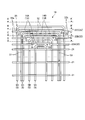
- FIG. 2 is a side view when the heat transfer tube group of the steam generator is viewed from the out-of-plane direction.
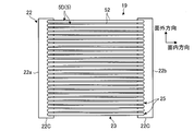
- FIG. 3 is a plan view of the heat transfer tube group in FIG.
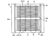
- FIG. 4 is a plan view of the heat transfer tube group of FIG. 2 taken along the line B-B ′.
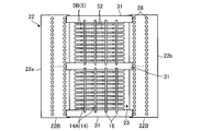
- FIG. 5 is a C-C ′ plan view of the heat transfer tube group of FIG. 2.
- 6 is a plan view of the heat transfer tube group in FIG. 2 taken along the line D-D ′.
- FIG. 7 is an explanatory diagram of an example relating to the method of assembling the steam generator according to the first embodiment.
- FIG. 7 is an explanatory diagram of an example relating to the method of assembling the steam generator according to the first embodiment.
- FIG. 8 is an explanatory diagram of an example related to the method of assembling the steam generator according to the first embodiment.
- FIG. 9 is an explanatory diagram of an example relating to the method of assembling the steam generator according to the first embodiment.
- FIG. 10 is an explanatory diagram of an example related to the method of assembling the steam generator according to the first embodiment.
- FIG. 11 is a flowchart relating to the method of assembling the steam generator according to the first embodiment.
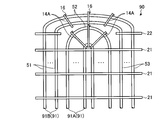
- FIG. 12 is a plan view of the heat transfer tube group of the steam generator according to the second embodiment.
- FIG. 13 is a side view when the heat exchanger tube group of the steam generator concerning Example 3 is seen from the out-of-plane direction.
- FIG. 1 is a schematic side sectional view of a steam generator according to a first embodiment.
- a steam generator 1 used in a pressurized water reactor (PWR: Pressurized Water Reactor).
- a primary coolant for example, light water
- the primary coolant that has become high temperature and high pressure is subjected to heat exchange with the secondary coolant, thereby evaporating the secondary coolant to generate steam, and primary cooling that has become high temperature and pressure.
- the material is cooling.
- the steam generator 1 extends in the vertical direction and has a sealed hollow space.
- the steam generator 1 has a pressure vessel 2 whose lower half is narrower than the upper half.
- the pressure vessel 2 is provided with a tube group outer cylinder 3 arranged at a predetermined distance from the inner wall surface of the pressure vessel 2 in the lower half portion thereof.
- the lower end portion of the tube group outer cylinder 3 extends to the vicinity of the tube plate 4 disposed below in the lower half of the pressure vessel 2.
- a heat transfer tube group 19 is provided in the tube group outer tube 3.
- the heat transfer tube group 19 includes a plurality of heat transfer tubes 5, and each heat transfer tube 5 is supported by the tube plate 4 at both ends on the lower side, and the intermediate portion has a plurality of first tube support plates 21 and second tubes. It is supported by the tube group outer cylinder 3 via the tube support plate 22 (see FIG. 2).
- the heat transfer tube group 19, the first tube support plate 21, and the second tube support plate 22 will be described later.
- the water chamber 7 is provided at the lower end of the pressure vessel 2.
- the water chamber 7 is divided into an entrance chamber 71 and an exit chamber 72 by a partition wall 8.
- the entrance chamber 71 communicates with one end of each heat transfer tube 5, and the exit chamber 72 communicates with the other end of each heat transfer tube 5.
- the entrance chamber 71 is formed with an inlet nozzle 74 that communicates with the outside of the pressure vessel 2, and the exit chamber 72 is formed with an exit nozzle 75 that communicates with the outside of the pressure vessel 2.
- the inlet nozzle 74 is connected to a cooling water pipe (not shown) through which a primary coolant is sent from the pressurized water reactor, and the outlet nozzle 75 passes the primary coolant after heat exchange to the pressurized water reactor.
- the cooling water piping (not shown) to send is connected.
- the steam / water separator 9 that separates the secondary coolant after heat exchange into steam (gas phase) and hot water (liquid phase), and the moisture content of the separated steam
- a moisture separator 10 is provided to remove the water and bring it to a state close to dry steam.
- a water supply pipe 11 for supplying water from the outside into the pressure vessel 2 is inserted into the pressure vessel 2.
- the pressure vessel 2 has a steam outlet 12 formed at the upper end thereof.
- the pressure vessel 2 has a pipe plate in the lower half of which the secondary coolant supplied from the water supply pipe 11 into the pressure vessel 2 flows down between the pressure vessel 2 and the tube group outer cylinder 3.
- a water supply path 13 is formed that is folded back at 4 and raised along the heat transfer tube group 19.
- the steam outlet 12 is connected to a cooling water pipe (not shown) for sending steam to the turbine, and the water supply pipe 11 has two steams used in the turbine cooled by a condenser (not shown).
- a cooling water pipe (not shown) for supplying the next coolant is connected.
- the primary coolant heated in the pressurized water reactor is sent to the entrance chamber 71 and circulates through the numerous heat transfer tubes 5 to reach the exit chamber 72.
- the secondary coolant cooled by the condenser is sent to the water supply pipe 11 and rises along the heat transfer pipe group 19 through the water supply path 13 in the trunk portion 2. At this time, heat exchange is performed between the high-temperature and high-pressure primary coolant and the secondary coolant in the pressure vessel 2. Then, the cooled primary coolant is returned from the exit chamber 72 to the pressurized water reactor.
- the secondary coolant that has exchanged heat with the high-temperature and high-pressure primary coolant rises in the pressure vessel 2 and is separated into steam and hot water by the steam / water separator 9.
- the separated steam is sent to the turbine after moisture is removed by the moisture separator 10.
- FIG. 2 is a side view when the heat transfer tube group of the steam generator is viewed from the out-of-plane direction.
- FIG. 3 is a plan view of the heat transfer tube group in FIG.
- FIG. 4 is a plan view of the heat transfer tube group of FIG. 2 taken along the line B-B ′.
- FIG. 5 is a C-C ′ plan view of the heat transfer tube group of FIG. 2.
- 6 is a plan view of the heat transfer tube group in FIG. 2 taken along the line D-D ′.
- the plurality of heat transfer tubes 5 constituting the heat transfer tube group 19 are supported at both ends by the tube plate 4, and the middle portion thereof includes the plurality of first tube support plates 21 and the plurality of first tubes. Supported by a two-tube support plate 22.
- each heat transfer tube 5 of the heat transfer tube group 19 includes a first tube portion 51, a second tube portion 52, and a third tube portion 53.
- the first pipe portion 51 is a straight pipe straight from the tube plate 4 toward the upper side (top side) of the pressure vessel 2 in the vertical direction.
- the second pipe portion 52 is a straight pipe that is straight in the horizontal direction perpendicular to the vertical direction.
- the third pipe portion 53 is a straight pipe that is straight in the vertical direction extending from the tube plate 4 toward the upper side (top side) of the pressure vessel 2.
- the first tube portion 51 and the second tube portion 52 communicate with each other via a bent portion that is bent at a right angle, and the second tube portion 52 and the third tube portion 53 are connected via a bent portion that is bent at a right angle. Communicate. For this reason, the second pipe part 52 connects the first pipe part 51 and the third pipe part 53.
- each heat transfer tube 5 extends straight from the tube plate 4 toward the upper side (top side) of the pressure vessel 2, bends at a right angle, extends straight in the horizontal direction, and bends at a right angle again to be the tube plate 4. It extends straight down toward the bottom.
- the plurality of heat transfer tubes 5 formed in this manner are arranged side by side from the center side of the hollow space of the pressure vessel 2 in the predetermined plane shown in FIG. 2 to form the heat transfer tube layer 25. ing. Then, as shown in FIG. 3, a plurality of heat transfer tube layers 25 are provided in the out-of-plane direction to form a heat transfer tube group 19. For this reason, the heat transfer tube group 19 includes a plurality of heat transfer tubes 5 arranged in the in-plane direction and arranged in the out-of-plane direction. That is, the plurality of heat transfer tubes 5 are arranged in a lattice shape called a square arrangement.
- the plurality of heat transfer tubes 5 include a plurality of first heat transfer tubes 5A, a plurality of second heat transfer tubes 5B, a plurality of third heat transfer tubes 5C, and a plurality of fourth heat transfer tubes 5D. have.
- FIG. 2 only one of the first heat transfer tube 5A, the second heat transfer tube 5B, the third heat transfer tube 5C, and the fourth heat transfer tube 5D is shown in order to simplify the description.
- the first heat transfer tube 5 ⁇ / b> A is the heat transfer tube 5 provided on the center side of the pressure vessel 2 in the in-plane direction of the heat transfer tube layer 25.
- the first heat transfer tube 5 ⁇ / b> A is supported only by the plurality of first tube support plates 21.
- the second heat transfer tube 5B is a heat transfer tube 5 provided outside the first heat transfer tube 5A so as to cover the first heat transfer tube 5A in the in-plane direction of the heat transfer tube layer 25.
- the second heat transfer tube 5B is supported by a plurality of first tube support plates 21 and a second tube support plate 22A described later.
- the third heat transfer tube 5 ⁇ / b> C is the heat transfer tube 5 provided outside the second heat transfer tube 5 ⁇ / b> B so as to cover the second heat transfer tube 5 ⁇ / b> B in the in-plane direction of the heat transfer tube layer 25.
- the third heat transfer tube 5C is supported by a plurality of first tube support plates 21 and second tube support plates 22A and 22B described later.
- the fourth heat transfer tube 5D is the heat transfer tube 5 provided outside the third heat transfer tube 5C so as to cover the third heat transfer tube 5C in the in-plane direction of the heat transfer tube layer 25.
- the fourth heat transfer tube 5D is supported by a plurality of first tube support plates 21 and second tube support plates 22A, 22B, and 22C described later.
- the inner heat transfer tube on the center side of the pressure vessel 2 is a heat transfer tube on the inner side (center side) of the outer heat transfer tube. Therefore, if the fourth heat transfer tube 5D is an outer heat transfer tube, the inner heat transfer tubes are the third heat transfer tube 5C, the second heat transfer tube 5B, and the first heat transfer tube 5A. Similarly, when the third heat transfer tube 5C is an outer heat transfer tube, the inner heat transfer tubes are the second heat transfer tube 5B and the first heat transfer tube 5A, and when the second heat transfer tube 5B is the outer heat transfer tube, the inner heat transfer tube is The first heat transfer tube 5A.
- the outer heat transfer tube outside the pressure vessel 2 in the in-plane direction of the heat transfer tube layer 25 is a heat transfer tube outside the inner heat transfer tube. Therefore, if the first heat transfer tube 5A is an inner heat transfer tube, the outer heat transfer tubes are the second heat transfer tube 5B, the third heat transfer tube 5C, and the fourth heat transfer tube 5D. Similarly, when the second heat transfer tube 5B is an inner heat transfer tube, the outer heat transfer tubes are the third heat transfer tube 5C and the fourth heat transfer tube 5D. Similarly, when the third heat transfer tube 5C is an inner heat transfer tube, the outer heat transfer tube is a fourth heat transfer tube 5D.
- the length of the second heat transfer tube 5B from the tube plate 4 of the first tube portion 51 and the third tube portion 53 is as follows.
- the first heat transfer tube 5A is longer than the lengths of the first tube portion 51 and the third tube portion 53 from the tube plate 4.
- the length from the tube plate 4 of the first tube portion 51 and the third tube portion 53 of the third heat transfer tube 5C is the tube plate of the first tube portion 51 and the third tube portion 53 of the second heat transfer tube 5B. It is longer than the length from 4.
- the length from the tube plate 4 of the first tube portion 51 and the third tube portion 53 of the fourth heat transfer tube 5D is the tube plate of the first tube portion 51 and the third tube portion 53 of the third heat transfer tube 5C. It is longer than the length from 4.
- the plurality of first tube support plates 21 and the plurality of second tube support plates 22 will be described.
- the plurality of first tube support plates 21 are provided at predetermined intervals in the vertical direction, and are arranged in parallel in a horizontal plane.
- the plurality of first tube support plates 21 support all of the plurality of heat transfer tubes 5.
- Each first tube support plate 21 is formed with a plurality of through holes (not shown), and the plurality of heat transfer tubes 5 are inserted into the plurality of through holes.
- the uppermost first tube support plate 21 is provided at a position above the first tube portion 51 and the third tube portion 53 of the first heat transfer tube 5A. .
- the plurality of second tube support plates 22 are provided at predetermined intervals in the vertical direction, like the plurality of first tube support plates 21, and are arranged in parallel in a horizontal plane.
- the plurality of second tube support plates 22 support some of the heat transfer tubes 5.
- Each second tube support plate 22 has a defective portion 23 in which a region facing the second tube portion 52 of the inner heat transfer tube is lost.
- each of the second tube support plates 22 includes a pair of separation plates 22 a including one separation plate 22 a that supports the first tube portion 51 and the other separation plate 22 b that supports the third tube portion 53. 22b.
- FIG. A plurality of through holes 28 are respectively formed in the pair of separation plates 22 a and 22 b, and a predetermined heat transfer tube 5 is inserted into the plurality of through holes 28.
- the pair of separation plates 22 a and 22 b are attached to the tube group outer cylinder 3 at the outer ends.
- the plurality of second tube support plates 22 includes a second tube support plate 22A, a second tube support plate 22B, and a second tube support plate 22C.
- the second tube support plate 22A is provided above the first tube support plate 21, and supports the second heat transfer tube 5B, the third heat transfer tube 5C, and the fourth heat transfer tube 5D.
- one separation plate 22a of the second tube support plate 22A supports the first tube portion 51 of the second heat transfer tube 5B, the third heat transfer tube 5C, and the fourth heat transfer tube 5D, and the second tube support plate 22A.
- the other separation plate 22b supports the third tube portion 53 of the second heat transfer tube 5B, the third heat transfer tube 5C, and the fourth heat transfer tube 5D.
- the second tube support plate 22A is provided at a position above the first tube portion 51 and the third tube portion 53 of the second heat transfer tube 5B.
- the second tube support plate 22B is provided above the second tube support plate 22A and supports the third heat transfer tube 5C and the fourth heat transfer tube 5D. That is, one separation plate 22a of the second tube support plate 22B supports the first tube portion 51 of the third heat transfer tube 5C and the fourth heat transfer tube 5D, and the other separation plate 22b of the second tube support plate 22B is The third heat transfer tube 5C and the third heat transfer tube 5D of the fourth heat transfer tube 5D are supported.
- the second tube support plate 22B is provided at a position above the first tube portion 51 and the third tube portion 53 of the third heat transfer tube 5C.
- the second tube support plate 22C is provided above the second tube support plate 22B and supports the fourth heat transfer tube 5D. That is, one separation plate 22a of the second tube support plate 22C supports the first tube portion 51 of the fourth heat transfer tube 5D, and the other separation plate 22b of the second tube support plate 22C is the fourth heat transfer tube 5D. 3rd pipe part 53 is supported.
- the second tube support plate 22C is provided at a position above the first tube portion 51 and the third tube portion 53 of the fourth heat transfer tube 5D.
- a plurality of bridge members 31 are attached to the pair of separation plates 22 a and 22 b of each second tube support plate 22. Each bridge member 31 is suspended between the pair of separation plates 22 a and 22 b, and the longitudinal direction thereof is the same as the axial direction of the second tube portion 52 of the heat transfer tube 5.
- the plurality of bridge members 31 are provided in parallel to each other. Each bridge member 31 has both ends attached to a pair of separation plates 22a and 22b. At this time, each bridge member 31 may have both ends fixed to the pair of separation plates 22a and 22b, one end fixed, and the other end movably attached in the longitudinal direction. .
- the plurality of bridge members 31 are suspended between the pair of separation plates 22a and 22b, respectively, thereby increasing the rigidity of the second tube support plate 22.
- the heat transfer tube group 19 is supported by the plurality of first tube support plates 21 and the plurality of second tube support plates 22, but when the primary coolant passes through each heat transfer tube 5, each heat transfer tube 5.
- a plurality of vibration suppressing members 14 that suppress vibrations of the heat transfer tubes 5 are provided in the second tube portion 52 of each heat transfer tube 5.
- the plurality of vibration suppression members 14 are arranged on the first vibration suppression member 14A inserted in the gap between adjacent heat transfer tube layers 25 arranged in parallel in the out-of-plane direction, and the plurality of heat transfer tube layers 25 stacked in the out-of-plane direction. It has the 2nd vibration suppression member 14B (refer FIG. 2) inserted ranging.
- Each vibration suppressing member 14 ⁇ / b> A is formed in a short rod shape, and is arranged so that the longitudinal direction thereof is the vertical direction perpendicular to the axial direction of the second tube portion 52 of the heat transfer tube 5. At this time, one end portion (upper end portion) of each vibration suppressing member 14 ⁇ / b> A is arranged to protrude upward from the heat transfer tube 5.
- the plurality of vibration suppressing members 14A are provided for each of the first heat transfer tube 5A, the second heat transfer tube 5B, and the third heat transfer tube 5C.
- the fourth heat transfer tube 5 ⁇ / b> D is not provided with the vibration suppressing member 14 ⁇ / b> A, but the vibration suppressing member 14 ⁇ / b> A may be appropriately provided and is not particularly limited.
- the plurality of vibration suppression members 14 ⁇ / b> A provided for the first heat transfer tube 5 ⁇ / b> A is in the gap between the two heat transfer tube layers 25 adjacent (stacked) in the out-of-plane direction. It arrange
- the upper ends of the vibration suppressing members 14 ⁇ / b> A arranged side by side are arranged in a plurality of rows along the in-plane direction of the heat transfer tube layer 25. That is, the upper end portions of the plurality of vibration suppressing members 14A are arranged in a lattice shape.
- the other end (lower end) of the plurality of vibration suppressing members 14A may be provided by being joined to the first tube support plate 21 or may be provided in contact with the first tube support plate 21.
- the first tube support plate 21 may be provided apart from the first tube support plate 21.
- the plurality of vibration suppressing members 14 ⁇ / b> A provided for the second heat transfer tube 5 ⁇ / b> B are spaced at predetermined intervals along the in-plane direction of the heat transfer tube layer 25, similarly to the first heat transfer tube 5 ⁇ / b> A. And arranged in a line in the out-of-plane direction of the heat transfer tube layer 25. For this reason, the upper end portions of the plurality of vibration suppressing members 14A provided for the second heat transfer tube 5B are also arranged in a lattice shape.
- the plurality of vibration suppressing members 14 ⁇ / b> A provided for the third heat transfer tube 5 ⁇ / b> C is a predetermined interval along the in-plane direction of the heat transfer tube layer 25, similarly to the first heat transfer tube 5 ⁇ / b> A. And arranged in a line in the out-of-plane direction of the heat transfer tube layer 25. For this reason, the upper end portions of the plurality of vibration suppressing members 14A provided for the third heat transfer tube 5C are also arranged in a lattice shape.
- the upper ends of the plurality of vibration suppressing members 14A are attached to the holding member 16.
- the holding member 16 is suspended between a plurality of bridge members 31 provided in parallel.
- the holding member 16 is provided so as to extend in a direction orthogonal to the axial direction of the second tube portion 52 of the heat transfer tube 5 in the horizontal plane. That is, the holding member 16 is provided along the upper ends of the plurality of vibration suppressing members 14A arranged in a line in the out-of-plane direction.
- the upper ends of the plurality of vibration suppressing members 14A are joined to the holding member 16 by welding or the like.
- the vibration suppressing member 14A is a short rod-shaped member, a V-shaped member may be used, or a V-shaped member and a short rod-shaped member may be used in combination. Well, not particularly limited. Moreover, although the vibration suppressing member 14A is provided corresponding to each of the first heat transfer tube 5A, the second heat transfer tube 5B, and the third heat transfer tube 5C, the first heat transfer tube 5A, the second heat transfer tube 5B, and the third heat transfer tube are provided. You may use the elongate rod-shaped thing arrange
- each vibration suppression member 14 ⁇ / b> B is formed in a rod shape that is long in the longitudinal direction, and in the axial direction of the second tube portion 52 of the heat transfer tube 5 so that the longitudinal direction is an out-of-plane direction. Arranged orthogonally. Moreover, each vibration suppression member 14B is arrange
- the plurality of vibration suppressing members 14B are provided for each of the first heat transfer tube 5A, the second heat transfer tube 5B, the third heat transfer tube 5C, and the fourth heat transfer tube 5D. In FIG. 2, only the vibration suppressing member 14B provided in the third heat transfer tube 5C is shown.
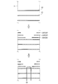
- FIG. 7 to FIG. 10 are explanatory diagrams of an example regarding the method of assembling the steam generator according to the first embodiment.
- FIG. 11 is a flowchart relating to the method of assembling the steam generator according to the first embodiment.
- This steam generator 1 is assembled when the heat transfer tube group 19 is disposed. This assembling method is performed in a state where the pressure vessel 2 is laid down.
- a plurality of first tube support plates 21 are provided at predetermined intervals from the bottom side of the pressure vessel 2 inside the tube group outer tube 3 provided in the pressure vessel 2.
- step S11 first tube support plate arranging step.
- step S12 Second pipe support plate arranging step).
- the plurality of heat transfer tubes 5 are sequentially disposed from the first heat transfer tube 5 ⁇ / b> A that is the most central in the in-plane direction. .
- the first heat transfer tube 5 ⁇ / b> A is inserted into the tube group outer cylinder 3 from both ends thereof, and is directed from the upper side (top side) to the lower side (bottom side) of the pressure vessel 2.
- the first heat transfer tubes 5A are attached to the plurality of first tube support plates 21 by being inserted through the through holes formed in the plurality of first tube support plates 21 (step S13). : Inner heat transfer tube mounting process).
- step S14 bridge member attachment step
- step S15 first vibration suppressing member attaching step
- the second heat transfer tube 5B is disposed outside the first heat transfer tube 5A as shown in the lower part of FIG. That is, in step S16, the second heat transfer tube 5B is inserted into the tube group outer tube 3 from both ends thereof, and moves from the upper side (top side) to the lower side (bottom side) of the pressure vessel 2. . At this time, the second heat transfer tube 5B is inserted while being inserted through the through holes 28 formed in each of the plurality of first tube support plates 21 and the second tube support plates 22A. It is attached to the plate 21 and the second tube support plate 22A (step S16: outer heat transfer tube attachment step).
- step S14 to step S16 are repeatedly performed for the heat transfer tubes outside the second heat transfer tube 5B. Specifically, since the third heat transfer tube 5C and the fourth heat transfer tube 5D are provided outside the second heat transfer tube 5B, step S14 to step S16 are repeated twice.
- step S14 bridge member attachment step
- step S15 first vibration suppressing member attaching step
- the third heat transfer tube 5C is disposed outside the second heat transfer tube 5B as shown in the middle part of FIG.
- the third heat transfer tube 5C is inserted while being inserted into the through holes 28 formed in each of the plurality of first tube support plates 21 and the plurality of second tube support plates 22A and 22B, thereby It attaches to the 1st pipe
- step S14 bridge member attachment step
- step S15 first vibration suppressing member attaching step
- the fourth heat transfer tube 5D is arranged outside the third heat transfer tube 5C as shown in the upper part of FIG. At this time, the fourth heat transfer tube 5D is inserted while being inserted through the through holes 28 formed in each of the plurality of first tube support plates 21 and the plurality of second tube support plates 22A, 22B, 22C. It is attached to the plurality of first tube support plates 21 and the plurality of second tube support plates 22A, 22B, 22C (step S16: outer heat transfer tube attachment step).
- step S17 second vibration suppression member mounting step
- Example 1 After performing 1st pipe support board arrangement
- the second tube support plate 22 is configured by the pair of separation plates 22a and 22b, so that the region between the pair of separation plates 22a and 22b is defined as the defect portion 23. can do. For this reason, since the unnecessary part of the 2nd pipe support plate 22 can be reduced, the weight of the 2nd pipe support plate 22 can be reduced. In addition, since the amount of heat given to the second tube support plate 22 can be reduced by the amount of the missing portion 23, thermal deformation of the second tube support plate 22 can be suppressed. Further, by providing the second tube support plate 22 with the defect 23, the inner heat transfer tube 5 can be easily accessed. For this reason, it becomes possible to easily perform the arrangement of the vibration suppressing member 14 or the maintenance of the heat transfer tube 5. From the above, it is possible to easily support the plurality of heat transfer tubes 5 provided in the pressure vessel 2, while reducing the load on the heat transfer tubes 5 and favorably supporting the plurality of heat transfer tubes 5.
- Example 1 by comprising the 2nd pipe
- the other separation plate 22b can be disposed on the third tube portion 53 of the heat transfer tube 5 that is disposed outside. For this reason, the 2nd pipe support plate 22 can be arrange
- Example 1 since the rigidity around the defect
- Example 1 since the vibration suppression member 14A can be arrange
- Example 1 since the vibration suppression member 14B can be arrange
- Example 1 since the 2nd pipe part 52 of the heat exchanger tube 5 can be made into a straight pipe, compared with the case where the 2nd pipe part 52 is formed in circular arc shape, it is 2nd pipe
- the periphery of the heat transfer tube 5 of the steam generator 1 can be assembled in the above-described process. Therefore, the plurality of heat transfer tubes 5 can be appropriately attached to the plurality of first tube support plates 21 and the plurality of second tube support plates 22, and the assembly around the heat transfer tubes 5 of the steam generator 1 is efficiently performed. It can be carried out.
- the plurality of heat transfer tubes 5 are arranged so that the heat transfer tube group 19 has a shape in plan view.
- the heat transfer tube group 19 has a circular shape in plan view.
- a plurality of heat transfer tubes 5 may be arranged.
- the several heat exchanger tube 5 was arrange
- These heat transfer tubes 5 may be arranged in a staggered manner (so-called triangular arrangement). In this case, it is preferable to omit the arrangement of the vibration suppressing member 14B.
- FIG. 12 is a plan view of the heat transfer tube group of the steam generator according to the second embodiment.
- the second tube support plate 22 is configured by a pair of separation plates 22a and 22b.
- the second tube support plate 80 has a hole. It is a tube support plate.
- the second tube support plate 80 of the steam generator of Example 2 has a square shape that is slightly larger than the heat transfer tube group 19 having a square shape in plan view, and has a through hole 81 inside. Is formed into a square ring shape.
- the through hole 81 is formed in a region facing the second tube portion 52 of the heat transfer tube 5 on the inner side.
- the second tube support plate 80 can be a tube support plate with a through hole 81.
- the 2nd pipe support plate 80 can be comprised with a single member, the 2nd pipe support plate 80 can be made into a highly rigid thing, and the heat exchanger tube 5 used as the outer side is supported suitably. be able to.
- the bridge member 31 may be attached to the second tube support plate 80 of the second embodiment.
- the bridge member 31 is preferably attached across the through hole 81 of the second tube support plate 80.
- the bridge member 31 may be provided in the same direction as the axial direction of the second pipe portion 52 of the heat transfer tube 5 as in the first embodiment, and unlike the first embodiment, the second of the heat transfer tubes 5 may be provided. You may provide in the orthogonal direction with respect to the axial direction of the pipe part 52.
- FIG. When the bridge member 31 is provided in a direction orthogonal to the axial direction of the second pipe portion 52, the holding member 16 is preferably attached to the second pipe support portion 80 so as to be parallel to the bridge member 31. .
- FIG. 13 is a side view when the heat exchanger tube group of the steam generator concerning Example 3 is seen from the out-of-plane direction.
- the second tube portion 52 of the heat transfer tube 5 is a straight tube.
- the second tube portion 52 of the heat transfer tube 91 is arcuate. It has become.
- the steam generator 90 of Example 3 is demonstrated.
- the plurality of heat transfer tubes 91 of the predetermined heat transfer tube layer 25 are a plurality of first heat transfer tubes 91A on the inside and a plurality of second heat transfer tubes 91A on the outside. And a heat transfer tube 91B.
- the first heat transfer tube 91A has a second tube portion 52 formed in an inverted U shape. That is, the second tube portion 52 of the first heat transfer tube 91A is a U-shaped arc formed with a predetermined curvature that protrudes upward.
- the second heat transfer tube 91B is provided outside the first heat transfer tube 91A so as to cover the first heat transfer tube 91A.
- the second heat transfer tube 91B has the second tube portion 52 formed in an inverted U shape. That is, the second tube portion 52 of the second heat transfer tube 91B is a U-shaped arc formed with a predetermined curvature that protrudes upward.
- the second heat transfer tube 91B covers the first heat transfer tube 91A, the length of the second heat transfer tube 91B from the tube plate 4 of the first tube portion 51 and the third tube portion 53 is the first.
- the heat transfer tube 91A is longer than the lengths of the first tube portion 51 and the third tube portion 53 from the tube plate 4.
- the 2nd pipe part 52 of the 2nd heat exchanger tube 91B is formed in the circular arc used as a big curvature radius compared with the 2nd pipe part 52 of 91 A of 1st heat exchanger tubes.
- the second tube portion 52 of the first heat transfer tube 91A has a substantially semicircular shape
- the second heat transfer tube 91B has a semi-elliptical shape whose major axis is the horizontal direction.
- the second tube support plate 22 supports the second heat transfer tube 91B, and the first tube portion 51 and the third tube portion of the second heat transfer tube 91B. It is provided at a position above 53.
- the plurality of vibration suppressing members 14A are formed in a short rod shape, and are arranged so that the longitudinal direction thereof is directed to the innermost heat transfer tube 91.
- one end portion (upper end portion) of each vibration suppression member 14 ⁇ / b> A is arranged to protrude upward from the heat transfer tube 91.
- the plurality of vibration suppressing members 14A are provided for each of the first heat transfer tube 91A and the second heat transfer tube 91B.
- the plurality of vibration suppressing members 14 ⁇ / b> A are attached to the holding member 16 at their upper ends.
- the holding member 16 is provided along the upper ends of the plurality of vibration suppressing members 14A.
- the upper ends of the plurality of vibration suppressing members 14A are joined to the holding member 16 by welding or the like.
- the second tube portion 52 of the first heat transfer tube 91A and the second heat transfer tube 91B can be formed into an arc, and the second tube of the second heat transfer tube 91B.
- the portion 52 can be formed in an arc having a larger radius of curvature than the second tube portion 52 of the first heat transfer tube 91A.
- the second tube portion 52 of the second heat transfer tube 91B can be positioned immediately above the second tube portion 52 of the first heat transfer tube 91A. Further, the first heat transfer tube 91A and the second heat transfer tube 91B may be gently bent between the first tube portion 51 and the second tube portion 52 and between the second tube portion 52 and the third tube portion 53. Therefore, the distribution of the first coolant can be made smooth.
Landscapes
- Engineering & Computer Science (AREA)
- Physics & Mathematics (AREA)
- Thermal Sciences (AREA)
- Mechanical Engineering (AREA)
- General Engineering & Computer Science (AREA)
- Life Sciences & Earth Sciences (AREA)
- Sustainable Development (AREA)
- Sustainable Energy (AREA)
- Geometry (AREA)
- Heat-Exchange Devices With Radiators And Conduit Assemblies (AREA)
Description
本発明は、内部に複数の伝熱管を有する蒸気発生器及び蒸気発生器の組立方法に関するものである。
従来、内部に複数の伝熱管を有する蒸気発生器として、特許文献1のものが知られている。特許文献1の蒸気発生器に設けられる伝熱管は、管板から鉛直方向の上方に伸び、直角に屈曲されて水平方向に伸び、直角に屈曲されて鉛直方向の下方の管板へ伸びて形成されている。この複数の伝熱管は、中心側の伝熱管と、中心側の伝熱管を覆う外側の伝熱管とを有している。蒸気発生器には、複数の伝熱管を固定する複数の管支持板が設けられており、複数の管支持板は、鉛直方向に所定の間隔を空けて設けられている。管支持板は、伝熱管の鉛直方向に伸びる部位に取り付けられている。また、管支持板は、中心側の伝熱管と外側の伝熱管との間にも設けられ、外側の伝熱管に取り付けられている。
しかしながら、特許文献1に記載の蒸気発生器に設けられる管支持板は、単一の板状(プレート状)に形成されているため、管支持板の重量が重くなる。また、単一の板状となる管支持板は、広域に亘って熱を受けることから、管支持板の熱変形量が大きくなるため、管支持板の変形によって、管支持板が取り付けられる伝熱管に対し過大な負荷を与えてしまう可能性がある。さらに、管支持板は、単一の板状(プレート状)に形成されていることから、管支持板の内側(下方側)が塞がれてしまうため、管支持板の内側にアクセスすることが困難となる。ここで、例えば、隣接する伝熱管の隙間には、伝熱管の振動を抑制するための振動抑制部材が、外側の伝熱管から中心側の伝熱管へ向けて挿入することがある。この場合、管支持板が単一の板状に形成されていると、管支持板の内側へのアクセスが困難であることから、振動抑制部材の挿入が管支持板によって妨げられてしまう。
そこで、本発明は、圧力容器の内部に設けられる複数の伝熱管へのアクセスを容易なものとしつつ、複数の伝熱管を好適に支持することができる蒸気発生器及び蒸気発生器の組立方法を提供することを課題とする。
本発明の蒸気発生器は、圧力容器と、圧力容器の内部に収容され、圧力容器の中心側に設けられる内側伝熱管と、内側伝熱管の外側に設けられる外側伝熱管とを含む複数の伝熱管と、内側伝熱管及び外側伝熱管を支持する第1管支持板と、外側伝熱管を支持する第2管支持板と、を備え、伝熱管は、圧力容器の底部側から頂部側に伸びる第1管部と、圧力容器の頂部側から底部側に伸びる第3管部と、第1管部と第3管部とをつなぐ第2管部と、を有し、外側伝熱管の第1管部及び第3管部は、内側伝熱管の第1管部及び第3管部に比して長く形成され、第1管支持板は、圧力容器の底部側に設けられ、内側伝熱管及び外側伝熱管の第1管部と第3管部とを支持し、第2管支持板は、第1管支持板よりも圧力容器の頂部側に位置し、内側伝熱管の第2管部と外側伝熱管の第2管部との間に設けられ、外側伝熱管の第1管部と第3管部とを支持し、且つ、内側伝熱管の第2管部と対向する領域を欠損させた欠損部を有していることを特徴とする。
この構成によれば、第2管支持板に欠損部を設けることで、第2管支持板おいて、外側伝熱管を支持する部位を残す一方で、外側伝熱管を支持しない不要な部位を減らすことができる。このため、第2管支持板の重量を低減することができる。また、欠損部を設けた分、第2管支持板に与えられる熱量を低減することができるため、第2管支持板の熱変形を抑制することができる。さらに、第2管支持板に欠損部を設けることで、内側伝熱管に対向する領域を開放することができるため、外側伝熱管から内側伝熱管へのアクセスを容易に行うことが可能となる。このため、振動抑制部材14の配設または伝熱管5のメンテナンス等を容易に行うことが可能となる。以上から、圧力容器の内部に設けられる複数の伝熱管へのアクセスを容易なものとしつつ、複数の伝熱管を好適に支持することができる。
この場合、第2管支持板は、欠損部を挟んで両側にそれぞれ設けられる一対の分離板であることが好ましい。
この構成によれば、外側伝熱管の第1管部に一方の分離板を配置し、外側伝熱管の第3管部に他方の分離板を配置することができるため、外側伝熱管を支持する部分にのみ第2管支持板を配置することができる。
この場合、第2管支持板は、欠損部を貫通穴とした穴付き管支持板であることが好ましい。
この構成によれば、第2管支持板を単一の部材で構成することができるため、第2管支持板を剛性の高いものとすることができ、外側伝熱管を好適に支持することができる。
この場合、第2管支持板の欠損部に懸架されるブリッジ部材をさらに備えることが好ましい。
この構成によれば、ブリッジ部材を設けることで、第2管支持板の欠損部周りの剛性を高めることができるため、第2管支持板を剛性の高いものとすることができ、外側伝熱管を好適に支持することができる。
この場合、複数の伝熱管は、所定の面内において内側伝熱管と外側伝熱管とが並べられることで伝熱管層を形成し、伝熱管層が所定の面に直交する面外方向に積層されることで伝熱管群を形成しており、伝熱管の振動を抑制する振動抑制部材をさらに備え、振動抑制部材は、面外方向に隣接する伝熱管層の隙間に配置されることが好ましい。
この構成によれば、面外方向に隣接する伝熱管層の隙間に振動抑制部材を配置することができるため、伝熱管の面外方向における振動を抑制することができる。
この場合、振動抑制部材は、所定の面の面内方向に隣接する伝熱管の隙間に配置されることが好ましい。
この構成によれば、面内方向に隣接する伝熱管の隙間に振動抑制部材を配置することができるため、伝熱管の面内方向における振動を抑制することができる。
この場合、伝熱管の第2管部は、直管となっていることが好ましい。
この構成によれば、第2管部を直管にすることができるため、第2管部の配置スペースを小さいものとすることができる。このため、第2管部の配置スペースを小さくできる分、第1管部及び第3管部を長くすることができる。
この場合、外側伝熱管の第2管部は、内側伝熱管の第2管部に比して大きな曲率半径となる円弧に形成されていることが好ましい。
この構成によれば、外側伝熱管及び内側伝熱管の第2管部を円弧にすることができ、また、外側伝熱管の第2管部を、内側伝熱管の第2管部に比して大きな曲率半径となる円弧に形成することができる。このため、外側伝熱管の第1管部及び第3管部を、内側伝熱管の第1管部及び第3管部に比して長くしても、外側伝熱管の第2管部の円弧が緩やかになることから、内側伝熱管の第2管部の直上に、外側伝熱管の第2管部を位置させることができる。また、外側伝熱管及び内側伝熱管の第1管部と第2管部との間を緩やかな屈曲にすることができため、第1冷却材の流通をスムーズなものにすることができる。
本発明の蒸気発生器の組立方法は、上記の蒸気発生器を組み立てる蒸気発生器の組立方法であって、圧力容器内の底部側に第1管支持板を配置する第1管支持板配置工程と、第1管支持板配置工程後に、第1管支持板よりも圧力容器内の頂部側に第2管支持板を配置する第2管支持板配置工程と、第1管支持板配置工程後に、第1管支持板に対し、内側伝熱管を取り付ける内側伝熱管取付工程と、内側伝熱管取付工程後に、第1管支持板及び第2管支持板に対し、外側伝熱管を取り付ける外側伝熱管取付工程と、を備えることを特徴とする。
この構成によれば、圧力容器内の底部側に第1管支持板を配置した後、圧力容器内の頂部側に第2管支持板を配置することができる。また、圧力容器内の底部側に第1管支持板を配置した後、内側伝熱管を第1管支持板に取り付けることができる。このとき、内側伝熱管の第1管支持板への取り付けは、第2管支持板の配置の前後のいずれに行ってもよい。そして、内側伝熱管を第1管支持板に取り付けた後、外側伝熱管を第1管支持板及び第2管支持板に取り付けることができる。このため、第1管支持板及び第2管支持板に対し、内側伝熱管及び外側伝熱管を適切に取り付けることができるため、蒸気発生器の組み立てを効率よく行うことができる。
この場合、蒸気発生器は、第2管支持板の欠損部に懸架されるブリッジ部材をさらに備え、第2管支持板の欠損部を跨いで、ブリッジ部材を第2管支持板に取り付けるブリッジ部材取付工程をさらに備えることが好ましい。
この構成によれば、ブリッジ部材を設けることで、第2管支持板の欠損部周りの剛性を高めることができるため、第2管支持板を剛性の高いものとすることができ、外側伝熱管を好適に支持することができる。
この場合、蒸気発生器は、伝熱管の振動を抑制する振動抑制部材をさらに備え、隣接する伝熱管の隙間に振動抑制部材を配置する振動抑制部材配置工程をさらに備えることが好ましい。
この構成によれば、隣接する伝熱管の隙間に振動抑制部材を配置することができるため、伝熱管の振動を抑制することができる。
以下に、本発明に係る実施例を図面に基づいて詳細に説明する。なお、この実施例によりこの発明が限定されるものではない。また、下記実施例における構成要素には、当業者が置換可能かつ容易なもの、あるいは実質的に同一のものが含まれる。
図1は、実施例1に係る蒸気発生器の側断面概略図である。伝熱管を内部に複数有する蒸気発生器として、例えば、加圧水型原子炉(PWR:Pressurized Water Reactor)に用いられる蒸気発生器1がある。この蒸気発生器1には、原子炉内を流通する原子炉冷却材及び中性子減速材としての一次冷却材(例えば、軽水)と、タービン内を流通する二次冷却材とが流入する。そして、蒸気発生器1では、高温高圧となった一次冷却材を、二次冷却材と熱交換させることにより、二次冷却材を蒸発させて蒸気を発生させ、かつ高温高圧となった一次冷却材を冷却している。
蒸気発生器1は、上下方向に延在し、かつ密閉された中空空間を有している。蒸気発生器1は、上半部に比して下半部が狭い幅となる圧力容器2を有している。圧力容器2は、その下半部内に、該圧力容器2の内壁面と所定間隔をもって配置された管群外筒3が設けられている。この管群外筒3は、その下端部が、圧力容器2の下半部内の下方に配置された管板4近傍まで延設されている。管群外筒3内には、伝熱管群19が設けられている。伝熱管群19は、複数の伝熱管5を有し、各伝熱管5は、下方側の両端部が管板4に支持されると共に、中間部が複数の第1管支持板21及び第2管支持板22(図2参照)を介して管群外筒3に支持されている。なお、伝熱管群19、第1管支持板21及び第2管支持板22については後述する。
圧力容器2は、その下端部に水室7が設けられている。水室7は、内部が隔壁8により入室71と出室72とに区画されている。入室71は、各伝熱管5の一端部が連通され、出室72は、各伝熱管5の他端部が連通されている。また、入室71は、圧力容器2の外部に通じる入口ノズル74が形成され、出室72は、圧力容器2の外部に通じる出口ノズル75が形成されている。そして、入口ノズル74は、加圧水型原子炉から一次冷却材が送られる冷却水配管(図示せず)が連結され、出口ノズル75は、熱交換された後の一次冷却材を加圧水型原子炉に送る冷却水配管(図示せず)が連結される。
圧力容器2は、その上半部内に、熱交換後の二次冷却材を蒸気(気相)と熱水(液相)とに分離する気水分離器9、および分離された蒸気の湿分を除去して乾き蒸気に近い状態とする湿分分離器10が設けられている。気水分離器9と伝熱管群19との間には、外部から圧力容器2内に二次冷却材の給水を行う給水管11が挿入されている。さらに、圧力容器2は、その上端部に、蒸気排出口12が形成されている。また、圧力容器2は、その下半部内に、給水管11からこの圧力容器2内に給水された二次冷却材を、圧力容器2と管群外筒3との間を流下させて管板4にて折り返させ、伝熱管群19に沿って上昇させる給水路13が形成されている。なお、蒸気排出口12は、タービンに蒸気を送る冷却水配管(図示せず)が連結され、給水管11は、タービンで使用された蒸気が復水器(図示せず)で冷却された二次冷却材を供給するための冷却水配管(図示せず)が連結される。
このような蒸気発生器1において、加圧水型原子炉で加熱された一次冷却材は、入室71に送られ、多数の伝熱管5内を通って循環して出室72に至る。一方、復水器で冷却された二次冷却材は、給水管11に送られ、胴部2内の給水路13を通って伝熱管群19に沿って上昇する。このとき、圧力容器2内で、高温高圧の一次冷却材と二次冷却材との間で熱交換が行われる。そして、冷却された一次冷却材は、出室72から加圧水型原子炉に戻される。一方、高温高圧の一次冷却材と熱交換を行った二次冷却材は、圧力容器2内を上昇し、気水分離器9で蒸気と熱水とに分離される。そして、分離された蒸気は、湿分分離器10で湿分が除去されてからタービンに送られる。
次に、図2から図6を参照して、伝熱管群19周りの構成について説明する。図2は、蒸気発生器の伝熱管群を面外方向から見たときの側面図である。図3は、図2の伝熱管群のA-A’視平面図である。図4は、図2の伝熱管群のB-B’視平面図である。図5は、図2の伝熱管群のC-C’視平面図である。図6は、図2の伝熱管群のD-D’視平面図である。
図1に示すように、伝熱管群19を構成する複数の伝熱管5は、その両端部が管板4に支持されると共に、その中間部が複数の第1管支持板21及び複数の第2管支持板22に支持される。
図2に示すように、伝熱管群19は、側面から見た形状が平面視方形状となっており、また、図3に示すように、上方から見た形状が平面視方形状となっている。伝熱管群19の各伝熱管5は、第1管部51と、第2管部52と、第3管部53とを有している。
第1管部51は、管板4から圧力容器2の上方側(頂部側)に向かって延在する上下方向に真っ直ぐな直管となっている。第2管部52は、上下方向に直交する水平方向に真っ直ぐな直管となっている。第3管部53は、管板4から圧力容器2の上方側(頂部側)に向かって延在する上下方向に真っ直ぐな直管となっている。そして、第1管部51と第2管部52とは、直角に屈曲する屈曲部を介して連通し、第2管部52と第3管部53とは、直角に屈曲する屈曲部を介して連通している。このため、第2管部52は、第1管部51と第3管部53とをつないでいる。よって、各伝熱管5は、管板4から圧力容器2の上方側(頂部側)に向かって真っ直ぐに伸び、直角に屈曲して水平方向に真っ直ぐに伸び、再び直角に屈曲して管板4へ向かって下方側に真っ直ぐに伸びている。
このように形成される複数の伝熱管5は、図2に示す所定の面内において、圧力容器2の中空空間の中心側から外側に向かって並べて設けられることで、伝熱管層25を形成している。そして、この伝熱管層25が、図3に示すように、面外方向に複数積層して設けられることで、伝熱管群19を形成している。このため、伝熱管群19は、複数の伝熱管5が、面内方向に揃って配置され、且つ、面外方向に揃って配置される。つまり、複数の伝熱管5は、四角配置と呼ばれる格子状に配置される。
所定の伝熱管層25において、複数の伝熱管5は、複数の第1伝熱管5Aと、複数の第2伝熱管5Bと、複数の第3伝熱管5Cと、複数の第4伝熱管5Dとを有している。なお、図2では、説明を簡単にするために、第1伝熱管5A、第2伝熱管5B、第3伝熱管5C及び第4伝熱管5Dを1本のみ図示している。
第1伝熱管5Aは、伝熱管層25の面内方向において、圧力容器2の中心側に設けられる伝熱管5である。第1伝熱管5Aは、複数の第1管支持板21によってのみ支持される。第2伝熱管5Bは、伝熱管層25の面内方向において、第1伝熱管5Aを覆うように、第1伝熱管5Aの外側に設けられた伝熱管5である。第2伝熱管5Bは、複数の第1管支持板21及び後述する第2管支持板22Aによって支持される。第3伝熱管5Cは、伝熱管層25の面内方向において、第2伝熱管5Bを覆うように、第2伝熱管5Bの外側に設けられた伝熱管5である。第3伝熱管5Cは、複数の第1管支持板21及び後述する第2管支持板22A、22Bによって支持される。第4伝熱管5Dは、伝熱管層25の面内方向において、第3伝熱管5Cを覆うように、第3伝熱管5Cの外側に設けられた伝熱管5である。第4伝熱管5Dは、複数の第1管支持板21及び後述する第2管支持板22A、22B、22Cによって支持される。
ここで、伝熱管層25の面内方向において、圧力容器2の中心側における内側伝熱管とは、外側伝熱管の内側(中心側)にある伝熱管である。このため、第4伝熱管5Dを外側伝熱管とすると、内側伝熱管は、第3伝熱管5C、第2伝熱管5B及び第1伝熱管5Aである。同様に、第3伝熱管5Cを外側伝熱管とすると、内側伝熱管は、第2伝熱管5B及び第1伝熱管5Aであり、第2伝熱管5Bを外側伝熱管とすると、内側伝熱管は、第1伝熱管5Aである。換言すれば、伝熱管層25の面内方向おいて、圧力容器2の外側における外側伝熱管とは、内側伝熱管の外側にある伝熱管である。このため、第1伝熱管5Aを内側伝熱管とすると、外側伝熱管は、第2伝熱管5B、第3伝熱管5C及び第4伝熱管5Dである。同様に、第2伝熱管5Bを内側伝熱管とすると、外側伝熱管は、第3伝熱管5C及び第4伝熱管5Dである。同様に、第3伝熱管5Cを内側伝熱管とすると、外側伝熱管は、第4伝熱管5Dである。
上記のように、第2伝熱管5Bは、第1伝熱管5Aを覆っているため、第2伝熱管5Bの第1管部51及び第3管部53の管板4からの長さは、第1伝熱管5Aの第1管部51及び第3管部53の管板4からの長さに比して長くなっている。同様に、第3伝熱管5Cの第1管部51及び第3管部53の管板4からの長さは、第2伝熱管5Bの第1管部51及び第3管部53の管板4からの長さに比して長くなっている。同様に、第4伝熱管5Dの第1管部51及び第3管部53の管板4からの長さは、第3伝熱管5Cの第1管部51及び第3管部53の管板4からの長さに比して長くなっている。
次に、複数の第1管支持板21及び複数の第2管支持板22について説明する。複数の第1管支持板21は、上下方向に所定間隔を空けて設けられており、水平面内において平行に配設されている。複数の第1管支持板21は、複数の伝熱管5の全てを支持している。各第1管支持板21には、複数の貫通孔(図示せず)が形成されており、複数の貫通孔内に複数の伝熱管5が挿通される。複数の第1管支持板21のうち、最も上方にある第1管支持板21は、第1伝熱管5Aの第1管部51及び第3管部53の上方となる位置に設けられている。
複数の第2管支持板22は、複数の第1管支持板21と同様に、上下方向に所定間隔を空けて設けられており、水平面内において平行に配設されている。複数の第2管支持板22は、複数の伝熱管5のうち、一部の伝熱管5を支持している。各第2管支持板22は、内側伝熱管の第2管部52と対向する領域を欠損させた欠損部23を有している。具体的に、各第2管支持板22は、第1管部51を支持する一方の分離板22aと、第3管部53を支持する他方の分離板22bとからなる一対の分離板22a、22bで構成されている。そして、一対の分離板22a、22bで挟まれた領域は、内側伝熱管が対向する領域となっており、この領域が欠損部23となる。一対の分離板22a、22bには、複数の貫通孔28がそれぞれ形成されており、複数の貫通孔28内に所定の伝熱管5が挿通される。一対の分離板22a、22bは、その外側の端部が管群外筒3に取り付けられている。
複数の第2管支持板22は、第2管支持板22Aと、第2管支持板22Bと、第2管支持板22Cとを含んで構成されている。図2及び図6に示すように、第2管支持板22Aは、第1管支持板21の上方に設けられ、第2伝熱管5B、第3伝熱管5C及び第4伝熱管5Dを支持している。つまり、第2管支持板22Aの一方の分離板22aは、第2伝熱管5B、第3伝熱管5C及び第4伝熱管5Dの第1管部51を支持し、第2管支持板22Aの他方の分離板22bは、第2伝熱管5B、第3伝熱管5C及び第4伝熱管5Dの第3管部53を支持している。この第2管支持板22Aは、第2伝熱管5Bの第1管部51及び第3管部53の上方となる位置に設けられている。
図2及び図5に示すように、第2管支持板22Bは、第2管支持板22Aの上方に設けられ、第3伝熱管5C及び第4伝熱管5Dを支持している。つまり、第2管支持板22Bの一方の分離板22aは、第3伝熱管5C及び第4伝熱管5Dの第1管部51を支持し、第2管支持板22Bの他方の分離板22bは、第3伝熱管5C及び第4伝熱管5Dの第3管部53を支持している。この第2管支持板22Bは、第3伝熱管5Cの第1管部51及び第3管部53の上方となる位置に設けられている。
図2及び図4に示すように、第2管支持板22Cは、第2管支持板22Bの上方に設けられ、第4伝熱管5Dを支持している。つまり、第2管支持板22Cの一方の分離板22aは、第4伝熱管5Dの第1管部51を支持し、第2管支持板22Cの他方の分離板22bは、第4伝熱管5Dの第3管部53を支持している。この第2管支持板22Cは、第4伝熱管5Dの第1管部51及び第3管部53の上方となる位置に設けられている。
各第2管支持板22の一対の分離板22a、22bには、複数のブリッジ部材31が取り付けられている。各ブリッジ部材31は、一対の分離板22a、22bの間に懸架されており、その長手方向が伝熱管5の第2管部52の軸方向と同方向となっている。複数のブリッジ部材31は、相互に平行に設けられている。各ブリッジ部材31は、その両端部が一対の分離板22a、22bにそれぞれ取り付けられている。このとき、各ブリッジ部材31は、その両端部が一対の分離板22a、22bに固定されてもよいし、その一端部が固定され、その他端部が長手方向に移動自在に取り付けられてもよい。複数のブリッジ部材31は、一対の分離板22a、22bの間にそれぞれ懸架されることで、第2管支持板22の剛性を高めている。
このように伝熱管群19は、複数の第1管支持板21及び複数の第2管支持板22によって支持されるが、一次冷却材が各伝熱管5内を通過する際、各伝熱管5の第2管部52において流体励起振動が発生する可能性がある。このため、各伝熱管5の第2管部52には、伝熱管5の振動を抑制する複数の振動抑制部材14が設けられる。
複数の振動抑制部材14は、面外方向に平行に並んだ隣接する伝熱管層25の隙間に挿入される第1振動抑制部材14Aと、面外方向に積層された複数の伝熱管層25に跨って挿入される第2振動抑制部材14B(図2参照)とを有している。
各振動抑制部材14Aは、短尺の棒状に形成されており、その長手方向が伝熱管5の第2管部52の軸方向に直交する上下方向となるように配置される。このとき、各振動抑制部材14Aの一方の端部(上端部)は、伝熱管5から上方側に突出して配置される。
複数の振動抑制部材14Aは、第1伝熱管5A、第2伝熱管5B及び第3伝熱管5Cのそれぞれに対して設けられている。なお、図2において、第4伝熱管5Dには、振動抑制部材14Aが設けられていないが、振動抑制部材14Aを適宜設けてもよく、特に限定されない。
図2及び図6に示すように、第1伝熱管5Aに対して設けられる複数の振動抑制部材14Aは、面外方向に隣り合う(積層される)2層の伝熱管層25の隙間において、伝熱管5の第2管部52の軸方向に沿って所定間隔を空けて配置される。このように、複数の振動抑制部材14Aが配設されることで、第1伝熱管5Aに対して設けられる複数の振動抑制部材14Aの上端部は、伝熱管層25の面外方向に一列に並んで配置され、また、一列となる振動抑制部材14Aの上端部は、伝熱管層25の面内方向に沿って複数列配設される。つまり、複数の振動抑制部材14Aの上端部は、格子状に配置される。なお、複数の振動抑制部材14Aの他方の端部(下端部)は、第1管支持板21に接合して設けてもよいし、第1管支持板21に接触させて設けてもよいし、第1管支持板21から離して設けてもよい。
図2及び図5に示すように、第2伝熱管5Bに対して設けられる複数の振動抑制部材14Aは、第1伝熱管5Aと同様に、伝熱管層25の面内方向に沿って所定間隔を空けて配置され、伝熱管層25の面外方向に一列に並んで配置される。このため、第2伝熱管5Bに対して設けられる複数の振動抑制部材14Aの上端部も、格子状に配置される。
図2及び図4に示すように、第3伝熱管5Cに対して設けられる複数の振動抑制部材14Aは、第1伝熱管5Aと同様に、伝熱管層25の面内方向に沿って所定間隔を空けて配置され、伝熱管層25の面外方向に一列に並んで配置される。このため、第3伝熱管5Cに対して設けられる複数の振動抑制部材14Aの上端部も、格子状に配置される。
これら複数の振動抑制部材14Aは、その上端部が保持部材16に取り付けられている。保持部材16は、平行に設けられる複数のブリッジ部材31の間に懸架されている。保持部材16は、水平面内において、伝熱管5の第2管部52の軸方向に直交する方向に延在して設けられている。つまり、保持部材16は、面外方向に一列に並ぶ複数の振動抑制部材14Aの上端部に沿って設けられる。複数の振動抑制部材14Aは、その上端部が保持部材16に溶接等により接合される。
なお、振動抑制部材14Aは、短尺の棒状のものを用いたが、V字形状のものを用いたり、あるいは、V字形状のものと短尺の棒状のものとを混在して用いたりしてもよく、特に限定されない。また、振動抑制部材14Aは、第1伝熱管5A、第2伝熱管5B及び第3伝熱管5Cのそれぞれに対応させて設けたが、第1伝熱管5A、第2伝熱管5B、第3伝熱管5C及び第4伝熱管5Dに跨って(貫いて)配設される長尺の棒状のものを用いてもよい。
図2に示すように、各振動抑制部材14Bは、長手方向に長い棒状に形成されており、その長手方向が面外方向となるように、伝熱管5の第2管部52の軸方向に直交させて配置される。また、各振動抑制部材14Bは、面内方向に隣り合う伝熱管5の隙間において、伝熱管5の第2管部52の軸方向に沿って所定間隔を空けて配置される。
複数の振動抑制部材14Bは、第1伝熱管5A、第2伝熱管5B、第3伝熱管5C及び第4伝熱管5Dのそれぞれに対して設けられている。なお、図2では、第3伝熱管5Cに設けられる振動抑制部材14Bのみ図示している。
次に、図7から図11を参照して、蒸気発生器1の組立方法について説明する。図7から図10は、実施例1に係る蒸気発生器の組立方法に関する一例の説明図である。図11は、実施例1に係る蒸気発生器の組立方法に関するフローチャートである。この蒸気発生器1の組立方法は、伝熱管群19を配設するときの組立方法である。また、この組立方法は、圧力容器2が横倒しされた状態で行われる。
先ず、図7の上段に示すように、圧力容器2に設けられる管群外筒3の内部には、複数の第1管支持板21が、圧力容器2の底部側から所定の間隔を空けて配置される(ステップS11:第1管支持板配置工程)。続いて、図7の中段に示すように、管群外筒3の内部には、複数の第2管支持板22が、圧力容器2の底部側から所定の間隔を空けて配置される(ステップS12:第2管支持板配置工程)。
複数の第1管支持板21及び複数の第2管支持板22が配置されると、複数の伝熱管5のうち、面内方向において最も中心側となる第1伝熱管5Aから順に配置される。図7の下段に示すように、第1伝熱管5Aは、その両端部から管群外筒3の内部に挿入され、圧力容器2の上方側(頂部側)から下方側(底部側)へ向けて移動する。このとき、第1伝熱管5Aは、複数の第1管支持板21のそれぞれに形成された貫通孔に挿通されながら挿入されることで、複数の第1管支持板21に取り付けられる(ステップS13:内側伝熱管取付工程)。
第1伝熱管5Aが複数の第1管支持板21に取り付けられると、図8の上段に示すように、第1伝熱管5Aの上方側にある第2管支持板22Aの一対の分離板22a、22bに、複数のブリッジ部材31が水平面内において平行に取り付けられる(ステップS14:ブリッジ部材取付工程)。複数のブリッジ部材31が取り付けられると、図8の中段に示すように、面外方向に隣接する第1伝熱管5Aの隙間に、複数の振動抑制部材14Aが挿入される。そして、複数の振動抑制部材14Aの挿入後、保持部材16をブリッジ部材31に取り付け、この後、保持部材16に各振動抑制部材14Aを接合する(ステップS15:第1振動抑制部材取付工程)。
第1伝熱管5Aに対する振動抑制部材14Aの取付が完了すると、図8の下段に示すように、第1伝熱管5Aの外側に第2伝熱管5Bが配置される。つまり、ステップS16では、第2伝熱管5Bが、その両端部から管群外筒3の内部に挿入され、圧力容器2の上方側(頂部側)から下方側(底部側)へ向けて移動する。このとき、第2伝熱管5Bは、複数の第1管支持板21及び第2管支持板22Aのそれぞれに形成された貫通孔28に挿通されながら挿入されることで、複数の第1管支持板21及び第2管支持板22Aに取り付けられる(ステップS16:外側伝熱管取付工程)。
そして、第2伝熱管5Bの外側にある伝熱管の分だけ、ステップS14からステップS16が繰り返し行われる。具体的に、第2伝熱管5Bの外側には、第3伝熱管5C及び第4伝熱管5Dが設けられるため、ステップS14からステップS16が2回繰り返される。
つまり、第2伝熱管5Bが複数の第1管支持板21及び第2管支持板22Aに取り付けられると、図9の上段に示すように、第2伝熱管5Bの上方側にある第2管支持板22Bの一対の分離板22a、22bに、複数のブリッジ部材31が水平面内において平行に取り付けられる(ステップS14:ブリッジ部材取付工程)。そして、複数のブリッジ部材31が取り付けられると、面外方向に隣接する第2伝熱管5Bの隙間に、複数の振動抑制部材14Aが挿入される。そして、複数の振動抑制部材14Aの挿入後、保持部材16をブリッジ部材31に取り付け、この後、保持部材16に各振動抑制部材14Aを接合する(ステップS15:第1振動抑制部材取付工程)。
第2伝熱管5Bに対する振動抑制部材14Aの取付が完了すると、図9の中段に示すように、第2伝熱管5Bの外側に第3伝熱管5Cが配置される。このとき、第3伝熱管5Cは、複数の第1管支持板21及び複数の第2管支持板22A、22Bのそれぞれに形成された貫通孔28に挿通されながら挿入されることで、複数の第1管支持板21及び複数の第2管支持板22A、22Bに取り付けられる(ステップS16:外側伝熱管取付工程)。
第3伝熱管5Cが複数の第1管支持板21及び第2管支持板22A、22Bに取り付けられると、図9の下段に示すように、第3伝熱管5Cの上方側にある第2管支持板22Cの一対の分離板22a、22bに、複数のブリッジ部材31が水平面内において平行に取り付けられる(ステップS14:ブリッジ部材取付工程)。そして、複数のブリッジ部材31が取り付けられると、面外方向に隣接する第3伝熱管5Cの隙間に、複数の振動抑制部材14Aが挿入される。そして、複数の振動抑制部材14Aの挿入後、保持部材16をブリッジ部材31に取り付け、この後、保持部材16に各振動抑制部材14Aを接合する(ステップS15:第1振動抑制部材取付工程)。
第3伝熱管5Cに対する振動抑制部材14Aの取付が完了すると、図10の上段に示すように、第3伝熱管5Cの外側に第4伝熱管5Dが配置される。このとき、第4伝熱管5Dは、複数の第1管支持板21及び複数の第2管支持板22A、22B、22Cのそれぞれに形成された貫通孔28に挿通されながら挿入されることで、複数の第1管支持板21及び複数の第2管支持板22A、22B、22Cに取り付けられる(ステップS16:外側伝熱管取付工程)。
複数の伝熱管5の取付が完了すると、面内方向に隣接する伝熱管5の隙間に、複数の振動抑制部材14Bが挿入される(ステップS17:第2振動抑制部材取付工程)。以上の工程をもって、蒸気発生器1の伝熱管5周りの組立が完了する。
なお、蒸気発生器1の組立方法は、上記した工程の順序に限定されない。実施例1では、第1管支持板配置工程S11後、第2管支持板配置工程S12を行った後、内側伝熱管取付工程S13を行った。しかしながら、例えば、第1管支持板配置工程S11後、内側伝熱管取付工程S13を行った後、第2管支持板配置工程S12を行ってもよい。また、実施例1では、ブリッジ部材取付工程S14を行った後、振動抑制部材取付工程S15を行ったが、振動抑制部材取付工程S15を行った後、ブリッジ部材取付工程S14を行ってもよい。この場合、工程を前後させることによるブリッジ部材31及び振動抑制部材14の取り付けに係る構成を適宜変更してもよい。
以上のように、実施例1の構成によれば、第2管支持板22を一対の分離板22a、22bで構成することにより、一対の分離板22a、22bの間の領域を欠損部23とすることができる。このため、第2管支持板22の不要な部位を減らすことができるため、第2管支持板22の重量を低減することができる。また、欠損部23を設けた分、第2管支持板22に与えられる熱量を低減することができるため、第2管支持板22の熱変形を抑制することができる。さらに、第2管支持板22に欠損部23を設けることで、内側の伝熱管5に対し、容易にアクセスすることが可能となる。このため、振動抑制部材14の配設または伝熱管5のメンテナンス等を容易に行うことが可能となる。以上から、圧力容器2の内部に設けられる複数の伝熱管5へのアクセスを容易なものとしつつ、伝熱管5に対する負荷を低減し、複数の伝熱管5を好適に支持することができる。
また、実施例1の構成によれば、第2管支持板22を一対の分離板22a、22bで構成することにより、外側となる伝熱管5の第1管部51に一方の分離板22aを配置し、外側となる伝熱管5の第3管部53に他方の分離板22bを配置することができる。このため、外側となる伝熱管5を支持する部分にのみ第2管支持板22を配置することができる。
また、実施例1の構成によれば、ブリッジ部材31を設けることで、第2管支持板22の欠損部23周りの剛性を高めることができるため、第2管支持板22を剛性の高いものとすることができ、外側となる伝熱管5を好適に支持することができる。
また、実施例1の構成によれば、面外方向に隣接する伝熱管層25の隙間に振動抑制部材14Aを配置することができるため、伝熱管5の面外方向における振動を抑制することができる。
また、実施例1の構成によれば、面内方向に隣接する伝熱管5の隙間に振動抑制部材14Bを配置することができるため、伝熱管5の面内方向における振動を抑制することができる。
また、実施例1の構成によれば、伝熱管5の第2管部52を直管にすることができるため、第2管部52を円弧状に形成する場合に比して、第2管部52の配置スペースを小さいものとすることができる。このため、第2管部52の配置スペースを小さくできる分、第1管部51及び第3管部53を長くすることができる。
また、実施例1の構成によれば、上記した工程で、蒸気発生器1の伝熱管5周りを組み立てることができる。このため、複数の第1管支持板21及び複数の第2管支持板22に対し、複数の伝熱管5を適切に取り付けることができ、蒸気発生器1の伝熱管5周りの組み立てを効率よく行うことができる。
なお、実施例1では、伝熱管群19が平面視方形状となるように複数の伝熱管5を配置したが、この構成に限らず、例えば、伝熱管群19が平面視円形状となるように複数の伝熱管5を配置してもよい。また、実施例1では、複数の伝熱管5を面内方向及び面外方向に揃う格子状に配置したが、この構成に限らず、伝熱管層25を面内方向において位置ずれさせることで複数の伝熱管5を千鳥状に配置(いわゆる三角配置)してもよい。この場合、振動抑制部材14Bの配置を省略することが好ましい。
次に、図12を参照して、実施例2に係る蒸気発生器について説明する。なお、実施例2では、実施例1と重複する記載を避けるべく、実施例1と異なる部分についてのみ言及する。図12は、実施例2に係る蒸気発生器の伝熱管群の平面図である。実施例1の蒸気発生器1は、第2管支持板22が一対の分離板22a、22bで構成されていたが、実施例2の蒸気発生器は、第2管支持板80が穴付きの管支持板となっている。以下、実施例2の蒸気発生器について説明する。
図12に示すように、実施例2の蒸気発生器の第2管支持板80は、平面視方形状となる伝熱管群19よりも一回り大きい方形状となっており、内側に貫通穴81が形成されることで、角形の環状に形成されている。貫通穴81は、内側となる伝熱管5の第2管部52と対向する領域に形成されている。
以上のように、実施例2の構成によれば、第2管支持板80を、貫通穴81付きの管支持板とすることができる。このため、第2管支持板80を単一の部材で構成することができるため、第2管支持板80を剛性の高いものとすることができ、外側となる伝熱管5を好適に支持することができる。
なお、実施例2の第2管支持板80にブリッジ部材31を取り付けてもよい。この場合、ブリッジ部材31は、第2管支持板80の貫通穴81を跨いで取り付けることが好ましい。このとき、ブリッジ部材31は、実施例1と同様に、伝熱管5の第2管部52の軸方向と同方向に設けてもよいし、実施例1とは異なり、伝熱管5の第2管部52の軸方向に対して直交方向に設けてもよい。なお、ブリッジ部材31を、第2管部52の軸方向に対して直交方向に設ける場合、保持部材16は、ブリッジ部材31に平行となるように、第2管支持部80に取り付けることが好ましい。
次に、図13を参照して、実施例3に係る蒸気発生器90について説明する。なお、実施例3でも、実施例1と重複する記載を避けるべく、実施例1と異なる部分についてのみ言及する。図13は、実施例3に係る蒸気発生器の伝熱管群を面外方向から見たときの側面図である。実施例1の蒸気発生器1は、伝熱管5の第2管部52が直管となっていたが、実施例3の蒸気発生器90は、伝熱管91の第2管部52が円弧状となっている。以下、実施例3の蒸気発生器90について説明する。
図13に示すように、実施例3の蒸気発生器90において、所定の伝熱管層25の複数の伝熱管91は、内側となる複数の第1伝熱管91Aと、外側となる複数の第2伝熱管91Bとを有している。
第1伝熱管91Aは、その第2管部52が逆U字状に形成されている。つまり、第1伝熱管91Aの第2管部52は、上方側に凸となる所定の曲率で形成されたU字形状の円弧となっている。第2伝熱管91Bは、第1伝熱管91Aを覆うように、第1伝熱管91Aの外側に設けられている。第2伝熱管91Bは、第1伝熱管91Aと同様に、その第2管部52が逆U字状に形成されている。つまり、第2伝熱管91Bの第2管部52は、上方側に凸となる所定の曲率で形成されたU字形状の円弧となっている。
ここで、第2伝熱管91Bは、第1伝熱管91Aを覆っているため、第2伝熱管91Bの第1管部51及び第3管部53の管板4からの長さは、第1伝熱管91Aの第1管部51及び第3管部53の管板4からの長さに比して長くなっている。また、第2伝熱管91Bの第2管部52は、第1伝熱管91Aの第2管部52に比して大きな曲率半径となる円弧に形成されている。例えば、第1伝熱管91Aの第2管部52は、ほぼ半円形状となっており、第2伝熱管91Bは、水平方向が長軸となる半楕円形状となっている。
上記のように構成された複数の伝熱管91に対し、第2管支持板22は、第2伝熱管91Bを支持しており、第2伝熱管91Bの第1管部51及び第3管部53の上方となる位置に設けられている。
また、上記のように構成された複数の伝熱管91に対し、複数の振動抑制部材14Aは、短尺の棒状に形成されており、その長手方向が最も内側の伝熱管91へ向かうように配置される。このとき、各振動抑制部材14Aの一方の端部(上端部)は、伝熱管91から上方側に突出して配置される。複数の振動抑制部材14Aは、第1伝熱管91A及び第2伝熱管91Bのそれぞれに対して設けられている。複数の振動抑制部材14Aは、その上端部が保持部材16に取り付けられている。保持部材16は、複数の振動抑制部材14Aの上端部に沿って設けられている。複数の振動抑制部材14Aは、その上端部が保持部材16に溶接等により接合される。
以上のように、実施例3の構成によれば、第1伝熱管91A及び第2伝熱管91Bの第2管部52を円弧にすることができ、また、第2伝熱管91Bの第2管部52を、第1伝熱管91Aの第2管部52に比して大きな曲率半径となる円弧に形成することができる。このため、第2伝熱管91Bの第1管部51及び第3管部53を、第1伝熱管91Aの第1管部51及び第3管部53に比して長くしても、第2伝熱管91Bの第2管部52の円弧を緩やかにできることから、第1伝熱管91Aの第2管部52の直上に、第2伝熱管91Bの第2管部52を位置させることができる。また、第1伝熱管91A及び第2伝熱管91Bの第1管部51と第2管部52との間、第2管部52と第3管部53との間を緩やかな屈曲にすることができるため、第1冷却材の流通をスムーズなものにすることができる。
1 蒸気発生器
2 圧力容器
3 管群外筒
4 管板
5 伝熱管
5A 第1伝熱管
5B 第2伝熱管
5C 第3伝熱管
5D 第4伝熱管
7 水室
8 隔壁
9 気水分離器
10 湿分分離器
11 給水管
12 蒸気排出口
13 給水路
14 振動抑制部材
14A 振動抑制部材
14B 振動抑制部材
16 保持部材
19 伝熱管群
21 第1管支持板
22 第2管支持板
22a、22b 分離板
23 欠損部
25 伝熱管層
31 ブリッジ部材
51 第1管部
52 第2管部
53 第3管部
71 入室
72 出室
74 入口ノズル
75 出口ノズル
80 第2管支持板(実施例2)
81 貫通穴
90 蒸気発生器(実施例3)
91 伝熱管(実施例3)
91A 第1伝熱管(実施例3)
91B 第2伝熱管(実施例3)
2 圧力容器
3 管群外筒
4 管板
5 伝熱管
5A 第1伝熱管
5B 第2伝熱管
5C 第3伝熱管
5D 第4伝熱管
7 水室
8 隔壁
9 気水分離器
10 湿分分離器
11 給水管
12 蒸気排出口
13 給水路
14 振動抑制部材
14A 振動抑制部材
14B 振動抑制部材
16 保持部材
19 伝熱管群
21 第1管支持板
22 第2管支持板
22a、22b 分離板
23 欠損部
25 伝熱管層
31 ブリッジ部材
51 第1管部
52 第2管部
53 第3管部
71 入室
72 出室
74 入口ノズル
75 出口ノズル
80 第2管支持板(実施例2)
81 貫通穴
90 蒸気発生器(実施例3)
91 伝熱管(実施例3)
91A 第1伝熱管(実施例3)
91B 第2伝熱管(実施例3)
Claims (11)
- 圧力容器と、
前記圧力容器の内部に収容され、前記圧力容器の中心側に設けられる内側伝熱管と、前記内側伝熱管の外側に設けられる外側伝熱管とを含む複数の伝熱管と、
前記内側伝熱管及び前記外側伝熱管を支持する第1管支持板と、
前記外側伝熱管を支持する第2管支持板と、を備え、
前記伝熱管は、前記圧力容器の底部側から頂部側に伸びる第1管部と、前記圧力容器の頂部側から底部側に伸びる第3管部と、前記第1管部と前記第3管部とをつなぐ第2管部と、を有し、
前記外側伝熱管の前記第1管部及び前記第3管部は、前記内側伝熱管の前記第1管部及び前記第3管部に比して長く形成され、
前記第1管支持板は、前記圧力容器の底部側に設けられ、前記内側伝熱管及び前記外側伝熱管の前記第1管部と前記第3管部とを支持し、
前記第2管支持板は、前記第1管支持板よりも前記圧力容器の頂部側に位置し、前記内側伝熱管の前記第2管部と前記外側伝熱管の前記第2管部との間に設けられ、前記外側伝熱管の前記第1管部と前記第3管部とを支持し、且つ、前記内側伝熱管の前記第2管部と対向する領域を欠損させた欠損部を有していることを特徴とする蒸気発生器。 - 前記第2管支持板は、前記欠損部を挟んで両側にそれぞれ設けられる一対の分離板であることを特徴とする請求項1に記載の蒸気発生器。
- 前記第2管支持板は、前記欠損部を貫通穴とする穴付き管支持板であることを特徴とする請求項1に記載の蒸気発生器。
- 前記第2管支持板の前記欠損部に懸架されるブリッジ部材をさらに備えることを特徴とする請求項1から3のいずれか1項に記載の蒸気発生器。
- 前記複数の伝熱管は、所定の面内において前記内側伝熱管と前記外側伝熱管とが並べられることで伝熱管層を形成し、前記伝熱管層が前記所定の面に直交する面外方向に積層されることで伝熱管群を形成しており、
前記伝熱管の振動を抑制する振動抑制部材をさらに備え、
前記振動抑制部材は、前記面外方向に隣接する前記伝熱管層の隙間に配置されることを特徴とする請求項1から4のいずれか1項に記載の蒸気発生器。 - 前記振動抑制部材は、前記所定の面の面内方向に隣接する前記伝熱管の隙間に配置されることを特徴とする請求項5に記載の蒸気発生器。
- 前記伝熱管の前記第2管部は、直管となっていることを特徴とする請求項1から6のいずれか1項に記載の蒸気発生器。
- 前記外側伝熱管の前記第2管部は、前記内側伝熱管の前記第2管部に比して大きな曲率半径となる円弧に形成されていることを特徴とする請求項1から6のいずれか1項に記載の蒸気発生器。
- 請求項1から8のいずれか1項に記載の蒸気発生器を組み立てる蒸気発生器の組立方法であって、
前記圧力容器内の底部側に前記第1管支持板を配置する第1管支持板配置工程と、
前記第1管支持板配置工程後に、前記第1管支持板よりも前記圧力容器内の頂部側に前記第2管支持板を配置する第2管支持板配置工程と、
前記第1管支持板配置工程後に、前記第1管支持板に対し、前記内側伝熱管を取り付ける内側伝熱管取付工程と、
前記内側伝熱管取付工程後に、前記第1管支持板及び前記第2管支持板に対し、前記外側伝熱管を取り付ける外側伝熱管取付工程と、を備えることを特徴とする蒸気発生器の組立方法。 - 前記蒸気発生器は、前記第2管支持板の前記欠損部に懸架されるブリッジ部材をさらに備え、
前記第2管支持板の前記欠損部を跨いで、前記ブリッジ部材を前記第2管支持板に取り付けるブリッジ部材取付工程をさらに備えることを特徴とする請求項9に記載の蒸気発生器の組立方法。 - 前記蒸気発生器は、前記伝熱管の振動を抑制する振動抑制部材をさらに備え、
隣接する前記伝熱管の隙間に前記振動抑制部材を配置する振動抑制部材配置工程をさらに備えることを特徴とする請求項9または10に記載の蒸気発生器の組立方法。
Applications Claiming Priority (2)
| Application Number | Priority Date | Filing Date | Title |
|---|---|---|---|
| JP2012-217723 | 2012-09-28 | ||
| JP2012217723A JP2014070821A (ja) | 2012-09-28 | 2012-09-28 | 蒸気発生器及び蒸気発生器の組立方法 |
Publications (1)
| Publication Number | Publication Date |
|---|---|
| WO2014050259A1 true WO2014050259A1 (ja) | 2014-04-03 |
Family
ID=50387676
Family Applications (1)
| Application Number | Title | Priority Date | Filing Date |
|---|---|---|---|
| PCT/JP2013/068954 Ceased WO2014050259A1 (ja) | 2012-09-28 | 2013-07-11 | 蒸気発生器及び蒸気発生器の組立方法 |
Country Status (2)
| Country | Link |
|---|---|
| JP (1) | JP2014070821A (ja) |
| WO (1) | WO2014050259A1 (ja) |
Families Citing this family (1)
| Publication number | Priority date | Publication date | Assignee | Title |
|---|---|---|---|---|
| JP7325955B2 (ja) * | 2018-12-25 | 2023-08-15 | 川崎重工業株式会社 | 伝熱管パネルの製造方法及び伝熱管パネル組立装置 |
Citations (2)
| Publication number | Priority date | Publication date | Assignee | Title |
|---|---|---|---|---|
| JPH05172487A (ja) * | 1991-06-06 | 1993-07-09 | Westinghouse Electric Corp <We> | 熱交換器及びその熱交換器管の振動除去方法 |
| JP2012102934A (ja) * | 2010-11-09 | 2012-05-31 | Mitsubishi Heavy Ind Ltd | 蒸気発生器の製造方法 |
-
2012
- 2012-09-28 JP JP2012217723A patent/JP2014070821A/ja active Pending
-
2013
- 2013-07-11 WO PCT/JP2013/068954 patent/WO2014050259A1/ja not_active Ceased
Patent Citations (2)
| Publication number | Priority date | Publication date | Assignee | Title |
|---|---|---|---|---|
| JPH05172487A (ja) * | 1991-06-06 | 1993-07-09 | Westinghouse Electric Corp <We> | 熱交換器及びその熱交換器管の振動除去方法 |
| JP2012102934A (ja) * | 2010-11-09 | 2012-05-31 | Mitsubishi Heavy Ind Ltd | 蒸気発生器の製造方法 |
Also Published As
| Publication number | Publication date |
|---|---|
| JP2014070821A (ja) | 2014-04-21 |
Similar Documents
| Publication | Publication Date | Title |
|---|---|---|
| EP2960614B1 (en) | Device and method for suppressing vibration of heat transfer tube, and steam generator | |
| KR102277764B1 (ko) | 증기 발생기 및 진동에 대항하여 증기 발생기 내에 관을 고정하는 방법 | |
| JP2003529740A (ja) | 熱交換器 | |
| ITMI20071686A1 (it) | Reattore nucleare raffreddato ad acqua in pressione, provvisto di generatori di vapore compatti | |
| RU2583321C1 (ru) | Парогенератор с горизонтальным пучком теплообменных труб и способ его сборки | |
| JPH08247686A (ja) | 熱交換装置 | |
| JPH0352594B2 (ja) | ||
| US9102024B2 (en) | Clearance increasing jig of heat transfer tube and additional installation method of vibration suppression member | |
| KR101255926B1 (ko) | 습기 분리 가열기 | |
| WO2014050259A1 (ja) | 蒸気発生器及び蒸気発生器の組立方法 | |
| JP5901244B2 (ja) | 蒸気発生器 | |
| JP5885949B2 (ja) | 蒸気発生器 | |
| JP7266586B2 (ja) | ボイラ構造体 | |
| WO2013002118A1 (ja) | 蒸気発生器 | |
| JP2009271066A (ja) | 蒸気乾燥器 | |
| JP2016090190A (ja) | 熱交換器、蒸気発生器、及び熱交換器の組立方法 | |
| JP6499478B2 (ja) | 蒸気発生器及び原子力プラント、並びに蒸気発生器の耐震補強方法 | |
| JP5901266B2 (ja) | 蒸気発生器 | |
| JP2012220077A (ja) | 蒸気発生器用給水管 | |
| JP2016084971A (ja) | 蒸気発生器および伝熱管支持方法 | |
| JP2012102934A (ja) | 蒸気発生器の製造方法 | |
| JP5862213B2 (ja) | タワーボイラの建造方法 | |
| US20140116360A1 (en) | Method and apparatus for securing tubes in a steam generator against vibration | |
| JPH04252812A (ja) | 湿分分離加熱器 | |
| JP2014047993A (ja) | 伝熱管の隙間拡張治具及び振動抑制部材の配設方法 |
Legal Events
| Date | Code | Title | Description |
|---|---|---|---|
| 121 | Ep: the epo has been informed by wipo that ep was designated in this application |
Ref document number: 13841458 Country of ref document: EP Kind code of ref document: A1 |
|
| NENP | Non-entry into the national phase |
Ref country code: DE |
|
| 122 | Ep: pct application non-entry in european phase |
Ref document number: 13841458 Country of ref document: EP Kind code of ref document: A1 |