WO2014050207A1 - データ生成システムおよびデータ生成方法 - Google Patents
データ生成システムおよびデータ生成方法 Download PDFInfo
- Publication number
- WO2014050207A1 WO2014050207A1 PCT/JP2013/065014 JP2013065014W WO2014050207A1 WO 2014050207 A1 WO2014050207 A1 WO 2014050207A1 JP 2013065014 W JP2013065014 W JP 2013065014W WO 2014050207 A1 WO2014050207 A1 WO 2014050207A1
- Authority
- WO
- WIPO (PCT)
- Prior art keywords
- data
- configuration data
- data generation
- specifications
- generation system
- Prior art date
- Legal status (The legal status is an assumption and is not a legal conclusion. Google has not performed a legal analysis and makes no representation as to the accuracy of the status listed.)
- Ceased
Links
Images





Classifications
-
- G—PHYSICS
- G05—CONTROLLING; REGULATING
- G05B—CONTROL OR REGULATING SYSTEMS IN GENERAL; FUNCTIONAL ELEMENTS OF SUCH SYSTEMS; MONITORING OR TESTING ARRANGEMENTS FOR SUCH SYSTEMS OR ELEMENTS
- G05B19/00—Program-control systems
- G05B19/02—Program-control systems electric
- G05B19/04—Program control other than numerical control, i.e. in sequence controllers or logic controllers
- G05B19/042—Program control other than numerical control, i.e. in sequence controllers or logic controllers using digital processors
- G05B19/0426—Programming the control sequence
-
- G—PHYSICS
- G05—CONTROLLING; REGULATING
- G05B—CONTROL OR REGULATING SYSTEMS IN GENERAL; FUNCTIONAL ELEMENTS OF SUCH SYSTEMS; MONITORING OR TESTING ARRANGEMENTS FOR SUCH SYSTEMS OR ELEMENTS
- G05B19/00—Program-control systems
- G05B19/02—Program-control systems electric
- G05B19/418—Total factory control, i.e. centrally controlling a plurality of machines, e.g. direct or distributed numerical control [DNC], flexible manufacturing systems [FMS], integrated manufacturing systems [IMS] or computer integrated manufacturing [CIM]
-
- G—PHYSICS
- G05—CONTROLLING; REGULATING
- G05B—CONTROL OR REGULATING SYSTEMS IN GENERAL; FUNCTIONAL ELEMENTS OF SUCH SYSTEMS; MONITORING OR TESTING ARRANGEMENTS FOR SUCH SYSTEMS OR ELEMENTS
- G05B2219/00—Program-control systems
- G05B2219/30—Nc systems
- G05B2219/45—Nc applications
- G05B2219/45031—Manufacturing semiconductor wafers
Definitions
- the present invention relates to a data generation system and a data generation method for generating configuration data for operating a substrate processing apparatus in accordance with the specifications of the substrate processing apparatus.
- the substrate processing apparatus includes an apparatus that performs processing such as etching, development, cleaning, and drying on the substrate.
- the substrate includes a semiconductor wafer, a photomask glass substrate, a liquid crystal display glass substrate, a plasma display glass substrate, an FED (Field Emission Display) substrate, an optical disk substrate, a magnetic disk substrate, and a magneto-optical disk.
- Various substrates such as a substrate are included.
- the substrate processing apparatus is a custom-designed production type product, and even if it is the same model, the hardware, mechanism, etc. are often different for each product. Therefore, when generating software for controlling the substrate processing apparatus, configuration data is generated as described in Patent Document 1, for example. That is, the computer program that is the center of the software is made common to various substrate processing apparatuses, and the individual functions of the computer program are switched according to the destination, user requirements, product specifications, etc. of each apparatus by configuration.
- the “product specification” is determined by the component parts constituting the product and the function of each part.
- the specification including “product specification” and “destination” and “user request” is simply referred to as “specification” in the present specification.
- the first problem is that it takes a considerable amount of man-hours to generate data.
- a description mistake at the time of data generation is likely to occur, and it is difficult to determine the validity of the data.
- a high level of expertise is required to generate high-quality configuration data at present.
- the present invention has been made in view of the above problems, and provides a data generation technique for generating high-quality configuration data for operating the substrate processing apparatus in accordance with the specifications of the substrate processing apparatus with a small number of work steps. For the purpose.
- One aspect of the present invention is a data generation system that generates configuration data for operating a substrate processing apparatus in accordance with the specifications of the substrate processing apparatus, and includes a plurality of different specifications and a plurality of different configuration data. Is stored in a hierarchical structure, and a storage unit for storing related information indicating the relationship between specifications and configuration data between layers, a specification acquisition unit for acquiring specifications of a substrate processing apparatus, and a specification acquisition unit Data generation unit for selecting configuration data corresponding to the specified specification from the plurality of configuration data based on the related information and generating configuration data for operating the substrate processing apparatus having the specification acquired by the specification acquisition unit And comprising.
- a data generation method for generating configuration data for operating a substrate processing apparatus in accordance with the specifications of the substrate processing apparatus.
- a process for generating a knowledge database including hierarchical information obtained by hierarchizing the configuration data of the data and related information indicating a relation between the specification and the configuration data, and a configuration corresponding to the specifications of the substrate processing apparatus And a step of selecting a configuration data from a knowledge database based on related information, and a step of using the selected configuration data as configuration data for operating the substrate processing apparatus.
- knowledge in this specification means the total knowledge that determines the correspondence of data. For example, the knowledge that “the substrate processing apparatus requires an X unit in order to realize the A function in the substrate processing apparatus” and “parts a and b related to using the X unit are necessary, The knowledge that “c is unnecessary” and the knowledge that “the substrate processing apparatus delivered to the Y factory in X country can select the Z1 requirement but cannot select the Z2 requirement due to safety standards” are knowledges, etc. Related information corresponds to knowledge.
- a database including the related information together with the specification and configuration data corresponds to a “knowledge database”.
- configuration data is hierarchically structured in association with the specifications of the substrate processing apparatus.
- specifications and configuration data are stored in a knowledge database in a form that is easy for software developers (hereinafter referred to as “workers”) to understand.
- the knowledge database includes related information indicating the relationship between the specifications and the configuration data between the hierarchies. Then, configuration data corresponding to the specifications of the substrate processing apparatus is selected from the knowledge database based on the related information. Therefore, it is possible to reduce the man-hours and description mistakes of the worker when generating data. In addition, it is easy to determine the validity of the data. As a result, high-quality configuration data can be generated with a small number of work steps.
- FIG. 1 It is a block diagram which shows the structure of one Embodiment of the data generation system concerning this invention. It is a figure which shows notionally the structure of the knowledge database memorize
- FIG. 1 It is a figure which shows an example of the configuration data produced
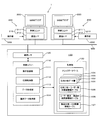
- FIG. 1 is a block diagram showing a configuration of an embodiment of a data generation system according to the present invention.
- the data generation system 1 includes a system server 100 that generates configuration data for operating the apparatus corresponding to the specifications of the substrate processing apparatus, and a client terminal 200 on which a WEB browser is mounted.
- the system server 100 and the client terminal 200 can communicate with each other via a communication network 300, for example, the Internet using a standardized communication protocol such as TCP / IP (Transmission Control Protocol / Internet Protocol).
- TCP / IP Transmission Control Protocol / Internet Protocol
- the client terminal 200 includes a terminal main body 210, a display unit 220 such as a liquid crystal display, and an operation unit 230 having a keyboard and a mouse.
- the terminal body 210 includes a control unit 211 and a communication I / F 212 for communicating with the system server 100.
- the control unit 211 is mainly a computer having a CPU (Central Processing Unit) and a memory.
- the control unit 211 starts a WEB browser according to a program stored in the memory in advance, and displays display information created by the system server 100 on the display unit 220. Project.
- two client terminals 200 are provided for the system server 100.
- the number of client terminals 200 is not limited to this and is arbitrary.
- the system server 100 includes a control unit 110, a communication I / F 120 for communicating with the client terminal 200, and a storage unit 130 for storing a knowledge database.
- FIG. 2 is a diagram conceptually showing the structure of the knowledge database stored in the data generation system of FIG. 2 denotes configuration data, and the configuration data is also abbreviated as “CD” as appropriate in other drawings.
- the knowledge database has four data layers 131 to 134 and three tables 135 to 137 (FIG. 1). Among these data layers, the configuration data layer 134 is formed by a plurality of configuration data stored in the storage unit 130. The remaining data layers 131 to 133 are formed of data relating to various specifications of the substrate processing apparatus necessary for generating configuration data. In this embodiment, three types of “destination”, “user request”, and “product specification” are set as the specifications of the substrate processing apparatus for which configuration data is to be generated. The data relating to the destination, user request, and product specification is divided into a destination data layer 131 (FIG. 3), a user request data layer 132 (FIG. 4), and a product specification data layer 133 (FIG. 5), respectively. Is remembered.
- the data generation system 1 hierarchically holds data related to the above specifications.
- the data generation system 1 displays selectable specification data and allows the worker to select it, or automatically determines another specification data that matches the specification data specified by the worker and displays it in a chained manner.
- the configuration data is generated in cooperation with the worker. Details will be described later.
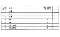
- the destination includes, for example, a country, a company and a factory where the substrate processing apparatus is installed as shown in FIG.
- a plurality of destination data are structured and stored in two stages in the destination data layer 131 of FIG.
- ID4 “Company X” and ID5 “Company Y” having a value of “Parent destination ID1” are associated with ID1 “USA”.
- ID6 “Y company Y1 factory” and ID7 “Y company Y2 factory” having a value of “parent destination ID 5” are associated with this ID5 “Y company”. Accordingly, by referring to the destination data layer 131, it is possible to automatically specify one or more destination data related to one destination data.
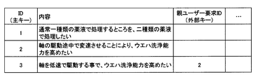
- the user request data layer 132 stores typical requests received from the user regarding the substrate processing apparatus as user request data. As shown in FIG. 4, for example, “Where to process with one type of chemical solution normally, but with two types of chemical solution” or “I want to increase the wafer cleaning capability by shifting the speed while driving the shaft. ".
- the data stored in the data layer 132 is also hierarchically structured so that the relevance of each user request data can be grasped. For example, ID2 “shaft driving at low speed” is indispensable for realizing “speed change during shaft drive” of ID2, and therefore the user request of ID2 and the user request of ID3 are related in a parent request-child request relationship. ing. That is, the child request cannot be made valid while the parent request remains invalid.
- the user request data is hierarchically structured, and one or a plurality of user requests related to the user request can be automatically set only by selecting one user request.
- the data related to the destination is positioned higher than the data related to the user request, and the storage unit 130 is in a state where the destination data layer 131 and the user request data layer 132 are hierarchically structured. Is remembered.
- information associating destinations with user requests is collected in a destination-user request related information table (hereinafter simply referred to as “upper table”) 135, and the storage unit 130.
- the user request ID2 is associated with the destination ID4 (ID4 “Company X” in FIG. 3). Therefore, when the destination ID 4 is selected by the worker, the user request data of the request ID 2 is valid.
- the user request ID 3 is associated with the destination ID 7 (ID 7 “Y company Y2 factory” in FIG. 3). Therefore, when the destination ID 7 is selected by the operator, the user request data of the request ID 3 is valid.
- the destination is designated, it is possible to automatically determine the content requested by the user based on the upper table 135.
- the data related to the user request is positioned above the data related to the product specification, and the “user request data layer 132” and the “product specification data layer 133” are hierarchically structured. It is stored in the storage unit 130.
- the product specification data layer 133 what kind of components the product (substrate processing apparatus) is configured and what functions each component has is managed in a database including optional components and functions. ing.
- FIG. 5 shows an example of the product specification data layer employed in this embodiment.
- FIG. 6A is a class diagram for explaining the product specification data layer, and is in accordance with a unified modeling language (UML) that is a specification description language standardized for object modeling in software engineering.
- UML unified modeling language
- reference numerals 133a to 133c denote “item class”, “part class”, and “function class”, respectively.
- the item class 133a is a part type that is a component of a product, can have a plurality of parts and functions, and has “name” as an attribute.
- the names of items constituting the substrate processing apparatus include “semiconductor cleaning apparatus”, “spin processing unit”, and the like.
- the part class 133b is a component of the product, and has “name”, “parent item”, “model item”, and “selection type (required, optional)” as attributes.
- a part having an item as a parent and having names “product 001”, “unit 001”, and the like is included.
- the function class 133c has “name”, “parent item / function”, and “selection type (required, optional)” as attributes.
- FIG. 4D a function having an item or function as a parent and having names “function 001”, “function 002”, and the like is included.
- the product specification data layer 133 stipulates the interrelation between components and functions that may be adopted by the substrate processing apparatus, and the distinction between essential / optional.
- items and parts are associated with each other.
- two types of spin processing units that is, “unit 001” (ID6) and “unit 002” (ID7) are associated with the semiconductor cleaning apparatus (ID1, name: “product 001”).
- ID6 two types of spin processing units
- ID7 the semiconductor cleaning apparatus
- ID1 name: “product 001”
- the selection type column of ID6 “unit 001” is an essential element
- unit 002 is an optional element.
- device 001 (ID8, name: motor)” and “device 002 (ID9, name: motor)” are associated with the spin processing unit (ID2) as optional components.
- the product specification data layer 133 associates items with functions. For example, “function 001” is associated with the semiconductor cleaning apparatus as an essential element. Further, “function 002” is associated with this “function 001” as an optional function. As described above, the function table holds data in a multilayer structure.
- intermediate table information associating user requests with product specifications is collected in a user request-product specification related information table (hereinafter simply referred to as “intermediate table”) 136 and stored in the storage unit 130. Is remembered. For example, as shown in the ID1 row, when the request ID1 is “valid”, a combination of the specification ID5 (“product 001” shown in FIG. 5C) and the specification ID7 (“unit 002”) is selected. It is set to be adopted as a product specification. Similarly, as shown in the ID2 row, when the request ID2 is “valid”, the specification ID5 (“product 001”), the specification ID6 (“unit 002”), and the specification ID8 (“device 001”) ) Is adopted as the product specification.
- the specification ID5 (“product 001”)
- the specification ID6 (“unit 002”)
- the specification ID9 (“device 002”)
- the product specification can be automatically determined based on the user request and the intermediate table 136.
- the configuration data can be automatically determined based on the product specification and the lower table 137.
- a hierarchical structure is formed in the order of destination, user request, product specification and configuration data, and destination-user request related information, user request-product specification related information and product. Specifications-Each specification and configuration data are associated based on configuration data related information.
- the control unit 110 is mainly a computer having a CPU and a memory, and functions as a display control unit 111, a specification acquisition unit 112, a data generation unit 113, and a selection data acquisition unit 114 according to a program stored in the memory in advance. .
- a WWW (World Wide Web) server program is operating, and display information stored in the memory can be browsed from the WEB browser of the client terminal 200.
- the display control unit 111 controls the display information and switches display contents displayed on the WEB browser. For example, when the operator operates the WEB browser of the client terminal 200 to request the entire display of the knowledge database, the display control unit 111 is based on the data layers 131 to 134 and the tables 135 to 137 stored in the storage unit 130. For example, as shown in FIG. 2, display information is created by hierarchically representing a knowledge database. As a result, a chart as shown in FIG. 2 is displayed on the display unit 220 by the WEB browser.
- FIG. 2 is a diagram conceptually showing the knowledge database, and shows a state in which the number of data in each data layer and the number of related information are greatly narrowed down for easy understanding of the concept.
- the specification acquisition unit 112 acquires information on the specification input by the worker from the client terminal 200 and gives the specification information to the data generation unit 113.
- the selection data acquisition unit 114 acquires information related to configuration data selected by the worker from the client terminal 200 and provides the selection data information to the data generation unit 113.
- the data generation unit 113 generates configuration data corresponding to the specification received from the specification acquisition unit 112 based on the knowledge database.
- the data generation unit 113 also has a knowledge database visualization function.
- the visualization function will be described with reference to FIGS. 10 and 12.
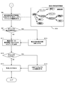
- FIG. 7 and 8 are flowcharts showing the operation of the data generation system shown in FIG.
- the operator instructs generation of configuration data via the client terminal 200 of the data generation system 1.
- the system server 100 generates configuration data suitable for the substrate processing apparatus in cooperation with the client terminal 200 while bidirectionally communicating with the client terminal 200 via the communication network 300.
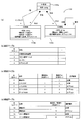
- a screen suitable for selecting a destination for example, a destination selection screen 221 as shown in the upper right part of FIG. 7 is displayed on the display unit 220 by the WEB browser.
- the destination is permitted to be input / edited by the user (step S1).
- the destinations are displayed in stages in the order of country, company, and factory, and the destinations can be easily narrowed down from the country level to the factory level according to the display. For example, when “Y2 factory” is selected as a destination by the WEB browser, the selected “Y2 factory” and related “Y company” and “US” are displayed brightly as shown in the selection screen 221. (It is hatched on the selection screen 221 in the figure).
- the operator when the destination of the substrate processing apparatus that is the target of data generation is already displayed on the selection screen 221, the operator operates the mouse or the like of the operation unit 230 as illustrated above. Select.
- the worker adds a new destination or changes the existing destination using the WEB browser. .
- the destination of the substrate processing apparatus is selected or input by the WEB browser, the destination is acquired in the system server 100 (step S2). Then, the validity / invalidity of each request is automatically set according to the destination-user request related information included in the upper table 135 (step S3).
- a user request setting screen 222 shown in the right center of FIG. 7 is displayed on the WEB browser, and the user request can be edited by the operator (step S4).
- the user request setting screen 222 displays the user requests (for example, request A, child request A-, request B, child request B-, B-) stored in the storage unit 130 and knowledged. Valid / invalid is automatically set for.
- the activated request or the child request is hatched.
- step S5 a case where there is a user request that is not stored in the storage unit 130, that is, there is a non-knowledge user request that has not been knowledged (in the case of “YES” in step S5) will be described.
- “Y2 factory” destination data layer 131)
- “user request A” user request data layer 132) are not associated with each other.
- “Y2 factory” is selected in step 1
- “user request A” is automatically invalidated based on the destination-user request related information.
- “Request A” is not displayed brightly.
- the worker selects “YES” in step S5.
- step S6 editing such as addition or change of a user request is accepted on the user request setting screen 222 (step S6).
- the operator can validate the current invalid request A by performing an editing operation such as a mouse operation on the screen 222.
- editing that enables only the child request A- while the parent request A remains invalid is not possible.
- relevance information indicating the association (“Y2 factory” ⁇ “request A” ⁇ “child request A ⁇ ”) between the request A acquired in step S2 and the upper hierarchy data is generated.
- the relevance information is data that is temporarily stored until configuration data setting is completed, and is not reflected in the destination-user request related information table 135.
- the editing / provisional holding operation for such non-knowledge data is the same for non-knowledge product usage and configuration data, which will be described later.
- step S5 When it is determined in step S5 that there is no non-knowledge user request, or when the editing in step S6 is completed, each product specification is adopted / not adopted according to the user request-product specification related information included in the intermediate table 136. It is automatically set (step S7). Further, for example, the product specification setting screen 223 shown in the upper right part of FIG. 8 is displayed on the display unit 220 by the WEB browser, and the product specification can be edited by the operator (step S8). In the setting screen 223 in the figure, the adopted product specifications (product, unit, subunit, function) are hatched.
- the product specification setting screen 223 displays the product specifications stored in the storage unit 130 and knowledged, and adoption / non-adoption is automatically set for each product specification.
- a WEB browser is used as in the case of a user request. Editing such as addition or change of product specifications is accepted (step S10).
- step S9 When it is determined in step S9 that there is no non-knowledge product specification or the editing in step S10 is completed, configuration data corresponding to the product specification-configuration data related information included in the lower table 137 is selectively extracted. And displayed on the display unit 220 by the WEB browser (step S11).
- step S11 when there is configuration data that is not stored in the storage unit 130, that is, there is non-knowledge configuration data that has not been knowledged ("YES" in step S12), as in the case of a user request, Editing such as addition or change of configuration data by the WEB browser is accepted (step S13).
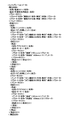
- step S12 If it is determined in step S12 that there is no non-knowledge configuration data, or if the editing in step S13 is completed, it is compatible with the substrate processing apparatus that is the target of data generation. For example, as shown in FIG. Configuration data in XML (Extensible Markup Language) format is completed. Then, the data generation system 1 outputs the configuration data (step S14). In the present embodiment, since the configuration data is described in the XML format, an XML database is used.
- XML Extensible Markup Language
- the destination, the user request, and the product specification are set as the specifications of the substrate processing apparatus, and the configuration data is associated with the structure in four layers. It has become.
- specifications and configuration data are stored in a knowledge database in a form that is easy for the operator to understand.
- the knowledge database includes three pieces of related information (knowledge) indicating the relationship between the destination data layer, the user request data layer, the product specification data layer, and the configuration data layer. Then, configuration data corresponding to the specifications of the substrate processing apparatus is selected from the knowledge database according to the related information. Therefore, it is possible to reduce the man-hours and description mistakes of the worker when generating data. In addition, it is easy to determine the validity of the data. As a result, high-quality configuration data can be efficiently generated with less work man-hours.
- the knowledge database is configured by the four data layers and the three related information, so that the data structure can be easily understood even in the order design production type business type.
- the knowledge database is inevitably complicated, and editing may be difficult.
- data selection in the upper data layer has a cascading effect on the lower data layer, and the effect may extend not only to the data layer directly below but also to the data layer positioned below.
- the data generation system 1 in FIG. 1 has two types of visualization functions: (1) a function for visualizing the forward effect of data selection on the upper data layer on the lower data layer; And a function for visualizing the reverse effect of the data selection in the lower data layer on the upper data layer. This makes it possible for an operator who does not have skills to intuitively understand how data selection in one hierarchy affects data in another hierarchy.
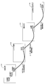
- FIG. 10 is a diagram conceptually showing the forward visualization function in the data generation system of FIG.
- the control unit 110 of the system server 100 visualizes the forward visualization stored in the memory in advance. Operates according to the program. More specifically, when data desired to be visualized by an operator (for example, the destination E in the destination data layer in FIG. 10) is selected by the WEB browser, the selection data and lower-level data affected by the selection data are selected. Only the layer data is displayed on the display unit 220 (FIG. 10). Thereby, the influence in the forward direction starting from the selected data can be intuitively and easily understood from the chart displayed on the display unit 220. In the example shown in FIG. 10, the destination is selected. However, when data in the user request data layer or the product specification data layer is selected, the influence on the forward direction starting from this is displayed on the display unit 220. .
- various specifications can be changed on this screen.
- the destination is changed from the destination E to the destination B by the operator.
- the data layer lower than the destination data layer 131 is rewritten in order, and the visualization program causes the chain effect of the specification change in the user request data layer 132 to be intuitive to the operator. Indicated.
- user requests and product specification setting changes as described in step S6 of FIG. 7 can be performed on this screen, and in this case also, the operator can intuitively understand the chain effect as shown in FIG. be able to.
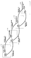
- FIG. 12 is a diagram conceptually showing the visualization function in the reverse direction in the data generation system of FIG.
- the control unit 110 of the system server 100 visualizes the reverse visualization stored in the memory in advance. Operates according to the program. More specifically, visualization in the direction opposite to the forward direction is performed. That is, when data desired to be visualized by the operator (for example, configuration data B in the configuration data layer in FIG. 12) is selected by the WEB browser, the selection data and the upper data layer affected by the selection data are selected. Is displayed on the display unit 220 (FIG. 12).
- the influence in the reverse direction from the selected data can be intuitively and easily understood from the chart displayed on the display unit 220.
- configuration data is selected.
- the influence in the reverse direction starting from this data is displayed on the display unit 220.
- the visualization function makes it easy to determine whether the related information is correct or missing, and the related information can be appropriately updated. Furthermore, the chart displayed on the display unit 220 by the visualization function can be used as a reference when finely adjusting the data set in the knowledge database. As a result, the knowledge database can be efficiently brushed up.
- the configuration data is described in the XML format.
- the data format is not limited to this, and other formats such as a CSV (CommaComSeparated Values) format and an INI format are available. Also good.
- CSV CommonComSeparated Values
- INI INI format
- the configuration data is in CSV format or INI format, it is preferable to use a relational database.
- the type of database is not limited to the XML database or the relational database, and this is also a data format. Similarly, it is optional.
- the client terminal 200 is provided and the WEB browser is activated on the client terminal 200 to perform various data selection and data editing.
- the client terminal 200 is not an essential component of the present invention.
- the system server 100 may be provided with a display unit or an operation unit so that the system server 100 executes all processes.
- the destination, user requirements and product specifications are set as the specifications of the substrate processing apparatus, and these three types of specifications are stored in a hierarchical structure.
- the number is arbitrary.
- the specification of the substrate processing apparatus is composed of two types or four or more types, the related information indicating the specification relationship between the layers is created and stored in the storage unit 130 as in the above embodiment. It is necessary to keep.
- the non-knowledged relevance information generated in step S6 or the like is merely temporarily stored and is not stored as permanent information.
- this information may be reflected as permanent information in a table such as the destination-user request related information table 135.
- the present invention can be applied to all data generation techniques for generating configuration data for operating a substrate processing apparatus in accordance with the specifications of the substrate processing apparatus.
Landscapes
- Engineering & Computer Science (AREA)
- Physics & Mathematics (AREA)
- General Physics & Mathematics (AREA)
- Automation & Control Theory (AREA)
- General Engineering & Computer Science (AREA)
- Manufacturing & Machinery (AREA)
- Quality & Reliability (AREA)
- Management, Administration, Business Operations System, And Electronic Commerce (AREA)
- Programmable Controllers (AREA)
- Stored Programmes (AREA)
- Exposure Of Semiconductors, Excluding Electron Or Ion Beam Exposure (AREA)
Description
100…システムサーバー
110…制御ユニット
111…表示制御部
112…仕様取得部
113…データ生成部
114…選択データ取得部
130…記憶部
131…仕向け地データ層
132…ユーザー要求データ層
133…製品仕様データ層
134…コンフィグレーションデータ層
135…仕向け地-ユーザー要求関連情報テーブル
136…ユーザー要求-製品仕様関連情報テーブル
137…製品仕様-コンフィグレーションデータ関連情報テーブル
220…表示部
Claims (8)
- 基板処理装置の仕様に対応して前記基板処理装置を動作させるためのコンフィグレーションデータを生成するデータ生成システムであって、
互いに異なる複数の仕様および互いに異なる複数のコンフィグレーションデータを階層構造化して記憶するとともに、仕様とコンフィグレーションデータとの階層間での関連を示す関連情報を記憶する記憶部と、
前記基板処理装置の仕様を取得する仕様取得部と、
前記仕様取得部が取得した仕様に対応するコンフィグレーションデータを前記関連情報に基づいて前記複数のコンフィグレーションデータから選択し、前記仕様取得部で取得した仕様を有する基板処理装置を動作させるためのコンフィグレーションデータを生成するデータ生成部と、
を備えるデータ生成システム。 - 請求項1に記載のデータ生成システムであって、
前記記憶部は、前記複数の仕様をさらに階層構造化して記憶するとともに、階層間での仕様の関連を示す関連情報を記憶するデータ生成システム。 - 請求項1または2に記載のデータ生成システムであって、
前記複数の仕様と前記複数のコンフィグレーションデータとの階層構造を表示する表示部をさらに備えるデータ生成システム。 - 請求項3に記載のデータ生成システムであって、
前記表示部は、前記仕様取得部が仕様を取得すると、前記仕様取得部に取得された当該仕様と当該仕様に関連するコンフィグレーションデータとの階層構造のみを選択的に表示するデータ生成システム。 - 請求項3に記載のデータ生成システムであって、
前記複数のコンフィグレーションデータから一の選択を受け取るデータ選択部をさらに備え、
前記表示部は、前記データ選択部がコンフィグレーションデータの選択を受け取ると、前記データ選択部に受け取られたコンフィグレーションデータと当該コンフィグレーションデータに関連する仕様との階層構造のみを選択的に表示するデータ生成システム。 - 請求項1ないし5のいずれか一項に記載のデータ生成システムであって、
前記データ生成部は、前記仕様取得部が取得した仕様に対応するコンフィグレーションデータが前記記憶部に含まれないとき、当該仕様に対応するコンフィグレーションデータの編集を許容するデータ生成システム。 - 請求項6に記載のデータ生成システムであって、
前記データ生成部は、編集された当該コンフィグレーションデータと、当該コンフィグレーションデータおよび前記仕様取得部が取得した仕様の関連情報とを前記記憶部に書き込むデータ生成システム。 - 基板処理装置の仕様に対応して前記基板処理装置を動作させるためのコンフィグレーションデータを生成するデータ生成方法であって、
予め互いに異なる複数の仕様および互いに異なる複数のコンフィグレーションデータを階層構造化した階層化情報と、仕様とコンフィグレーションデータとの階層間での関連を示す関連情報とを含むナレッジデータベースを生成する工程と、
前記基板処理装置の仕様に対応するコンフィグレーションデータを前記関連情報に基づいて前記ナレッジデータベースから選択する工程と、
選択されたコンフィグレーションデータを、前記基板処理装置を動作させるためのコンフィグレーションデータとする工程と
を備えるデータ生成方法。
Priority Applications (3)
| Application Number | Priority Date | Filing Date | Title |
|---|---|---|---|
| KR1020157003278A KR102061926B1 (ko) | 2012-09-28 | 2013-05-30 | 데이터 생성 시스템 및 데이터 생성 방법 |
| US14/431,572 US20150253763A1 (en) | 2012-09-28 | 2013-05-30 | Data generation system and data generation method |
| CN201380051038.5A CN104685468B (zh) | 2012-09-28 | 2013-05-30 | 数据生成系统以及数据生成方法 |
Applications Claiming Priority (2)
| Application Number | Priority Date | Filing Date | Title |
|---|---|---|---|
| JP2012216144A JP5969875B2 (ja) | 2012-09-28 | 2012-09-28 | データ生成システムおよびデータ生成方法 |
| JP2012-216144 | 2012-09-28 |
Publications (1)
| Publication Number | Publication Date |
|---|---|
| WO2014050207A1 true WO2014050207A1 (ja) | 2014-04-03 |
Family
ID=50387626
Family Applications (1)
| Application Number | Title | Priority Date | Filing Date |
|---|---|---|---|
| PCT/JP2013/065014 Ceased WO2014050207A1 (ja) | 2012-09-28 | 2013-05-30 | データ生成システムおよびデータ生成方法 |
Country Status (6)
| Country | Link |
|---|---|
| US (1) | US20150253763A1 (ja) |
| JP (1) | JP5969875B2 (ja) |
| KR (1) | KR102061926B1 (ja) |
| CN (1) | CN104685468B (ja) |
| TW (1) | TWI507901B (ja) |
| WO (1) | WO2014050207A1 (ja) |
Cited By (2)
| Publication number | Priority date | Publication date | Assignee | Title |
|---|---|---|---|---|
| TWI684177B (zh) * | 2018-06-29 | 2020-02-01 | 劉建宏 | 工作機械語音控制系統 |
| TWI848369B (zh) * | 2021-09-16 | 2024-07-11 | 日商斯庫林集團股份有限公司 | 處理裝置群管理系統、處理裝置群管理方法及記錄有程式之程式產品 |
Families Citing this family (5)
| Publication number | Priority date | Publication date | Assignee | Title |
|---|---|---|---|---|
| US11100415B2 (en) * | 2016-10-04 | 2021-08-24 | University Of Louisiana At Lafayette | Architecture and method for providing insights in networks domain |
| CN106874011B (zh) * | 2017-02-28 | 2020-06-09 | 南京南瑞继保电气有限公司 | 一种文件生成方法及装置 |
| JP7456199B2 (ja) * | 2020-03-04 | 2024-03-27 | オムロン株式会社 | ビジュアルプログラミングの補助方法、プログラム及びビジュアルプログラミング補助装置 |
| WO2026070483A1 (ja) * | 2024-09-26 | 2026-04-02 | 東京エレクトロン株式会社 | コンピュータプログラム、情報処理方法及び情報処理装置 |
| KR102949696B1 (ko) * | 2024-12-24 | 2026-04-06 | 주식회사 에이머슬리 | 하이라키 기반 구조화된 ai 프로젝트 정보를 출력하는 전자 장치 및 그의 ui 출력 방법 |
Citations (4)
| Publication number | Priority date | Publication date | Assignee | Title |
|---|---|---|---|---|
| JPH06222911A (ja) * | 1993-01-25 | 1994-08-12 | Sadao Kikuchi | パラメータ設定装置 |
| JP2000148221A (ja) * | 1998-11-17 | 2000-05-26 | Yamagata Casio Co Ltd | 部品搭載プログラム作成装置 |
| JP2002015968A (ja) * | 2000-06-28 | 2002-01-18 | Tokyo Electron Ltd | 半導体製造装置における入出力ボードの自動認識方法及び半導体製造装置 |
| JP2002342083A (ja) * | 2001-05-21 | 2002-11-29 | Denso Corp | ソフトウェア部品リスト作成装置 |
Family Cites Families (32)
| Publication number | Priority date | Publication date | Assignee | Title |
|---|---|---|---|---|
| US6192401B1 (en) * | 1997-10-21 | 2001-02-20 | Sun Microsystems, Inc. | System and method for determining cluster membership in a heterogeneous distributed system |
| US6466972B1 (en) * | 1999-03-31 | 2002-10-15 | International Business Machines Corporation | Server based configuration of network computers via machine classes |
| US7840652B2 (en) * | 2001-03-21 | 2010-11-23 | Ascentive Llc | System and method for determining network configuration settings that provide optimal network performance |
| EP1308810B1 (en) * | 2001-09-05 | 2005-11-16 | Mikron Comp-Tec AG | A method and an operator support system for assisting an operator in setting machine parameters |
| US7036008B2 (en) * | 2003-04-17 | 2006-04-25 | International Business Machines Corporation | Autonomic determination of configuration settings by walking the configuration space |
| US7529814B2 (en) * | 2003-10-15 | 2009-05-05 | International Business Machines Corporation | Autonomic computing algorithm for identification of an optimum configuration for a web infrastructure |
| US20050120340A1 (en) * | 2003-12-01 | 2005-06-02 | Skazinski Joseph G. | Apparatus, system, and method for automated generation of embedded systems software |
| US7580905B2 (en) * | 2003-12-15 | 2009-08-25 | Intel Corporation | Adaptive configuration of platform |
| CN1327341C (zh) * | 2004-01-13 | 2007-07-18 | 英业达股份有限公司 | 基板管理控制器的固件自动配置系统及方法 |
| DE102004005730A1 (de) * | 2004-02-05 | 2005-08-25 | Robert Bosch Gmbh | Verfahren zur Konfiguration eines Computerprogramms |
| US7376719B1 (en) * | 2004-04-14 | 2008-05-20 | Juniper Networks, Inc. | Automatic generation of configuration data using implementation-specific configuration policies |
| US20060047798A1 (en) * | 2004-07-13 | 2006-03-02 | Feinleib David A | System and method for automated capture, editing, replication, and deployment of server configurations |
| US7496594B1 (en) * | 2005-06-08 | 2009-02-24 | Unisys Corporation | User interface for displaying a hierarchical structure of a computer system |
| US20070135956A1 (en) * | 2005-12-13 | 2007-06-14 | Taiwan Semiconductor Manufacturing Co., Ltd. | Data location systems and methods |
| CN100481001C (zh) * | 2006-01-17 | 2009-04-22 | 大唐移动通信设备有限公司 | 界面自动生成方法和界面自动生成系统 |
| CA2648528C (en) * | 2006-04-21 | 2016-08-23 | Cirba Inc. | Method and system for determining compatibility of computer systems |
| US7680754B2 (en) * | 2006-04-21 | 2010-03-16 | Cirba Inc. | System and method for evaluating differences in parameters for computer systems using differential rule definitions |
| US7542973B2 (en) * | 2006-05-01 | 2009-06-02 | Sap, Aktiengesellschaft | System and method for performing configurable matching of similar data in a data repository |
| US7562004B2 (en) * | 2006-05-31 | 2009-07-14 | International Business Machines Corporation | Determining better configuration for computerized system |
| US8610725B2 (en) * | 2007-10-10 | 2013-12-17 | Apple Inc. | Framework for dynamic configuration of hardware resources |
| JP5356396B2 (ja) * | 2007-10-29 | 2013-12-04 | エヌイーシー ラボラトリーズ アメリカ インク | 分散確率ベースのアクティブサンプリング法を用いた最適なシステム構成の発見 |
| US8874705B1 (en) * | 2008-03-07 | 2014-10-28 | Symantec Corporation | Method and apparatus for identifying an optimal configuration of a resource |
| US8396582B2 (en) * | 2008-03-08 | 2013-03-12 | Tokyo Electron Limited | Method and apparatus for self-learning and self-improving a semiconductor manufacturing tool |
| US20090248716A1 (en) * | 2008-03-31 | 2009-10-01 | Caterpillar Inc. | Hierarchy creation and management tool |
| US8701047B2 (en) * | 2009-01-14 | 2014-04-15 | Microsoft Corporation | Configuration creation for deployment and monitoring |
| US8578059B2 (en) * | 2010-02-01 | 2013-11-05 | Invensys Systems, Inc. | Deploying a configuration for multiple field devices |
| TWI474143B (zh) | 2010-02-09 | 2015-02-21 | 日立國際電氣股份有限公司 | 基板處理系統及其資料處理方法、群管理裝置及其資料處理方法、半導體處理裝置之製造方法暨電腦可讀取記錄媒體 |
| US8819636B2 (en) * | 2010-06-23 | 2014-08-26 | Hewlett-Packard Development Company, L.P. | Testing compatibility of a computer application |
| US8527081B2 (en) * | 2010-08-31 | 2013-09-03 | Applied Materials, Inc. | Method and apparatus for automated validation of semiconductor process recipes |
| US20120123898A1 (en) * | 2010-11-17 | 2012-05-17 | International Business Machines Corporation | Generating configuration options for a computing system |
| US8364716B2 (en) * | 2010-12-17 | 2013-01-29 | Netapp, Inc. | Methods and apparatus for incrementally computing similarity of data sources |
| US8560827B1 (en) * | 2010-12-28 | 2013-10-15 | Emc International Company | Automatically determining configuration parameters for a system based on business objectives |
-
2012
- 2012-09-28 JP JP2012216144A patent/JP5969875B2/ja active Active
-
2013
- 2013-05-30 KR KR1020157003278A patent/KR102061926B1/ko active Active
- 2013-05-30 US US14/431,572 patent/US20150253763A1/en not_active Abandoned
- 2013-05-30 CN CN201380051038.5A patent/CN104685468B/zh active Active
- 2013-05-30 WO PCT/JP2013/065014 patent/WO2014050207A1/ja not_active Ceased
- 2013-06-11 TW TW102120790A patent/TWI507901B/zh active
Patent Citations (4)
| Publication number | Priority date | Publication date | Assignee | Title |
|---|---|---|---|---|
| JPH06222911A (ja) * | 1993-01-25 | 1994-08-12 | Sadao Kikuchi | パラメータ設定装置 |
| JP2000148221A (ja) * | 1998-11-17 | 2000-05-26 | Yamagata Casio Co Ltd | 部品搭載プログラム作成装置 |
| JP2002015968A (ja) * | 2000-06-28 | 2002-01-18 | Tokyo Electron Ltd | 半導体製造装置における入出力ボードの自動認識方法及び半導体製造装置 |
| JP2002342083A (ja) * | 2001-05-21 | 2002-11-29 | Denso Corp | ソフトウェア部品リスト作成装置 |
Cited By (2)
| Publication number | Priority date | Publication date | Assignee | Title |
|---|---|---|---|---|
| TWI684177B (zh) * | 2018-06-29 | 2020-02-01 | 劉建宏 | 工作機械語音控制系統 |
| TWI848369B (zh) * | 2021-09-16 | 2024-07-11 | 日商斯庫林集團股份有限公司 | 處理裝置群管理系統、處理裝置群管理方法及記錄有程式之程式產品 |
Also Published As
| Publication number | Publication date |
|---|---|
| CN104685468A (zh) | 2015-06-03 |
| JP2014072307A (ja) | 2014-04-21 |
| KR102061926B1 (ko) | 2020-01-02 |
| JP5969875B2 (ja) | 2016-08-17 |
| US20150253763A1 (en) | 2015-09-10 |
| KR20150063357A (ko) | 2015-06-09 |
| TW201413481A (zh) | 2014-04-01 |
| TWI507901B (zh) | 2015-11-11 |
| CN104685468B (zh) | 2018-06-01 |
Similar Documents
| Publication | Publication Date | Title |
|---|---|---|
| JP5969875B2 (ja) | データ生成システムおよびデータ生成方法 | |
| JP3827092B2 (ja) | 制御システム設定装置および制御システム設定方法ならびに設定プログラム | |
| US7668608B2 (en) | Graphical programming language object editing and reporting tool | |
| JP6880545B2 (ja) | プロセス制御システム、設定システム、およびコンピュータ可読記憶媒体 | |
| US10444949B2 (en) | Configurable user displays in a process control system | |
| US8516383B2 (en) | System and method for developing animated visualization interfaces | |
| CN104281119B (zh) | 支持分布式控制系统中的技术任务的方法和系统 | |
| US20040075688A1 (en) | System, method and computer program product for managing CAD data | |
| CN104216701B (zh) | 用于在制造执行系统内创建图形用户界面的系统和方法 | |
| JP6911279B2 (ja) | プロセス制御システム、設定システム、およびコンピュータ可読記憶媒体 | |
| WO2010022054A1 (en) | Method, computer, and computer program for displaying a hierarchical navigation scheme | |
| CN103403722A (zh) | 设计辅助系统 | |
| EP2891976B1 (en) | Software workstation and method for employing appended metadata in industrial automation software | |
| US20050086201A1 (en) | Converting user interface panels | |
| JP2006302297A (ja) | 制御システム設定装置および制御システム設定方法ならびに設定プログラム | |
| CN102257445B (zh) | 用于可视化地址空间的系统和方法 | |
| CN108459569A (zh) | 工业过程自动化系统的工程设计系统运行方法和控制程序 | |
| CN108228161A (zh) | 一种扩展结构化命令行的系统和方法 | |
| JP2001266171A (ja) | 作画装置および作画プログラムを記録したコンピュータ読み取り可能な記録媒体 | |
| JP4995009B2 (ja) | Pod画面生成装置、そのプログラム | |
| JP4691895B2 (ja) | データ処理システム設計装置及びそのためのコンピュータプログラム | |
| JP5347615B2 (ja) | データ管理装置およびデータ管理方法 | |
| TWI916859B (zh) | Scada web hmi系統 | |
| CN120257491B (zh) | 一种航天器仿真模型的界面编辑与数据驱动方法和装置 | |
| CN103792873B (zh) | 控制环境变化传达 |
Legal Events
| Date | Code | Title | Description |
|---|---|---|---|
| 121 | Ep: the epo has been informed by wipo that ep was designated in this application |
Ref document number: 13842913 Country of ref document: EP Kind code of ref document: A1 |
|
| ENP | Entry into the national phase |
Ref document number: 20157003278 Country of ref document: KR Kind code of ref document: A |
|
| WWE | Wipo information: entry into national phase |
Ref document number: 14431572 Country of ref document: US |
|
| NENP | Non-entry into the national phase |
Ref country code: DE |
|
| 122 | Ep: pct application non-entry in european phase |
Ref document number: 13842913 Country of ref document: EP Kind code of ref document: A1 |